xyz - cisco certified network associate -...
TRANSCRIPT

College full name
CITYSummer training Report
On
CCNA
-: Submitted by:-
XYZ
Roll No.(Branch)

ACKNOWLEDGEMENT
Though words are insufficient to acknowledge all my literacy depth, I wish
to express my deepest sense of gratitude to my esteemed guide Mr. –XYZ
(manager of IIT kanpur) for giving me an able guidance and scholarly supervision.
I express my sincere thanks to all those who had helped me out to training.
Finally I thank the almighty God by whose grace I find myself in the
position of putting forth my presentation.

CERTIFICATE
This is to certify that ( Student Name ) has completed his training
On “—IIT KANPUR” under my supervision.
The training has been well planned and beautifully presented. He has done a
Commendable job in preparing work that has taken up a lot of effort.
Internal Guide: External Guide:
Varun kumar Arvind Gupta

Table of Contents
1. Introduction 2. Router
3. Router component3.1. Processor3.2. Rom
3.3. Post 3.4. Bootstrap program
3.5. Mini-IOS 3.6. Rom monitor 3.7. Ram 3.8. Flash memory 3.9. NVram 3.10. Type of router 4. Routing protocols 4.1. Interior gateway routing protocol
4.2. Enhanced interior gateway routing protocol
5. Access control list
5.1. ACL Processing
5.2 Configuring ACL
6. Nat/Pat
6.1. Static and Dynamic Nat 7. Virtual local area network

CCNACCNA is a popular certification in computer networking developed by Cisco Systems. Cisco created the CCNA to recognize basic competency in installation and support of medium-sized networks.
RouterA Cisco router does not contain disk storage mechanisms such as hard disks. Therefore, the router requires certain hardware and firmware components for proper functioning.
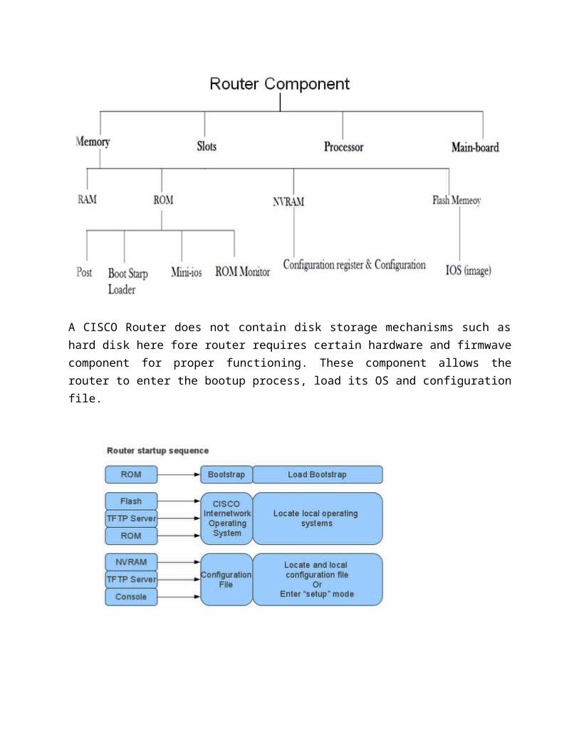
A CISCO Router does not contain disk storage mechanisms such as hard disk here fore router requires certain hardware and firmwave component for proper functioning. These component allows the router to enter the bootup process, load its OS and configuration file.
Processor
CISCO Router has a processor (C.P.U.) that executes the IOS commands using the other router components. The CISCO IOS software’s makes routing decisions and maintains routing table using the processor. The processor requires access to the memory either to get data for making routing decision or to get instruction for execution.
ROM
It is non-volatile memory storage device. It does not lose its contents when the power supply is turn off. The component of the rom decide the boot process of the router. To perform the rom upgrade, you must remove and replace pluggable chips on the motherboard.
In ROM there are following component
POST BootStrap Program Mini-IOS ROM Monitor
POST
The Power-On-Self-Test(POST) component provides a series of diagnostic tests for the router. These tests start when the router is switched on.
BootStrap Program
It is a Rom Monitor component that allows to initialize the processor hardware when the router boots. the components boots the OS software after initializing the processor hardware.
Mini-IOS
Its component is not present in every router. Its component provide an alternate file for the router boots up, if the existing image file is unavailable.
ROM Monitor
It is a program stored in the rom which used to debug user program. The rom monitor also allows manufacturing, testing and troubleshooting of ROM
RAM
The function of RAM in the router is similar to that of memory in a computer. The ram is a volatile storage medium that loses data when the device is switch off. The router ram consists of the active IOS image is loaded when the router boots.

Flash memory
The flash memory in a router is a non-volatile storage medium. it is basically EEPROM. The flash memory may contain IOS images using which the router can boot.
NVRAM
Non-Volatile-Memory is a type of random access memory that stores configuration files for the router. The ram is made Non-Volatile by attaching it to a constant source of power supply such as a battery. The startup file and the configuration register for the router are present in the NVRAM. The configuration register specifies the bootup options for the router.
Type of Router
There are two types of router-
1) Fixed Router2) Modular Router

1. Fixed Router- In fixed router we can’t change the card slots of the router according to our need. We can use only that card slot which is present in the router that is given to us.
2-Modular Router- In Modular Router we can change the card slots of the router according to our need. We can add or remove the card slots according to our need.
RoutingRouting is used for taking a packet from one device and sending it
through the network to another device on a different network. If your networkhas no routers, then you are not routing. Routers route traffic to all thenetworks in your internetwork. To be able to route packets, a router mustknow, at a minimum, the following:
Destination address
Neighbor routers from which it can learn about remote networks Possible routes to all remote networks The best route to each remote network How to maintain and verify routing information
The router learns about remote networks from neighbor routers or froman administrator. The router then builds a routing table that describes howto find the remote networks. If the network is directly connected, then therouter already knows how to get to the network. If the networks are notattached, the router must learn how to get to the remote network with eitherstatic routing, which means that the administrator must hand-type all networklocations into the routing table, or use dynamic routing.Dynamicroutingis the process of routing protocols running on the router communicatingwith neighbor routers. The routers then update each other about allthe networks they know about. If a change occurs in the network, thedynamic routing protocols automatically inform all routers about thechange. If static routing is used, the administrator is responsible for updatingall changes by hand into all routers.

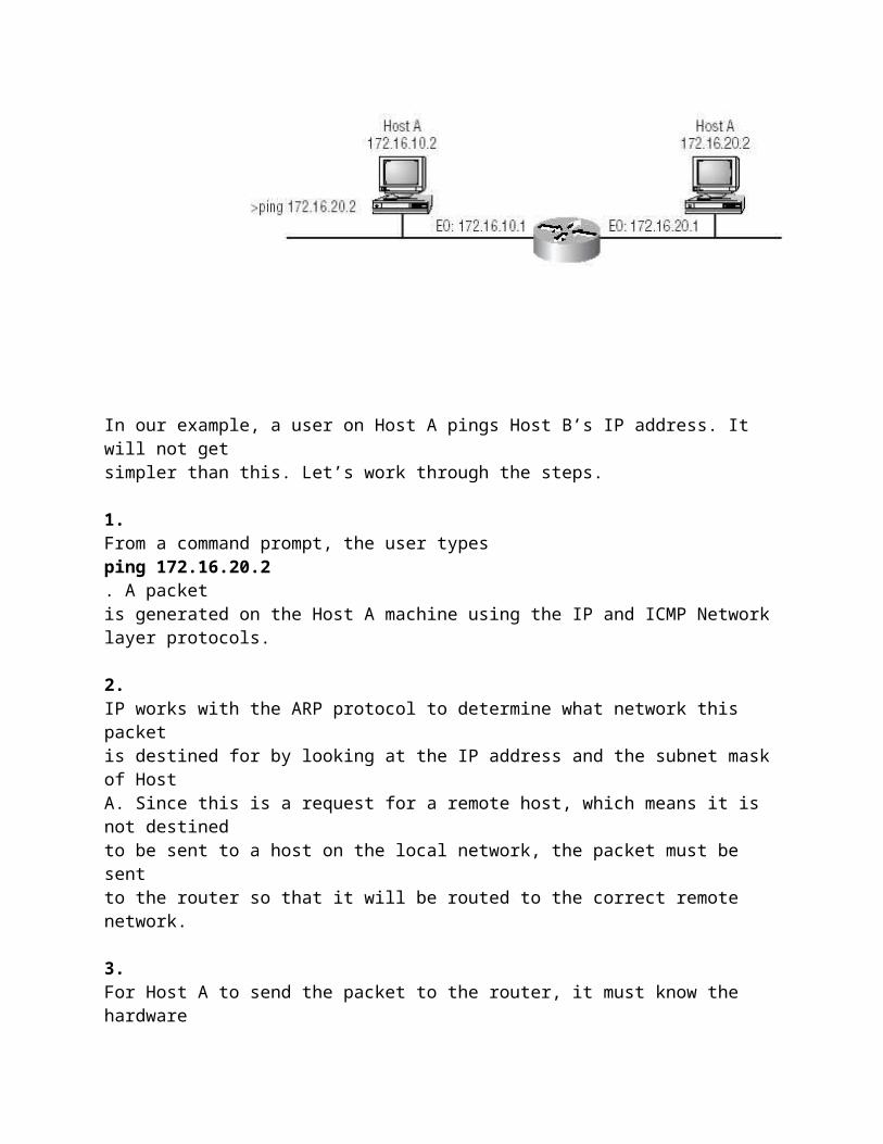
The IP Routing ProcessThe IP routing process is fairly simple and doesn’t change, regardlessof the size of network you have. For an example, we’ll use Figure 5.1 todescribe step by step what happens when Host A wants to communicate withHost B on a different network.
FIGURE 5 . 1IP routing example using two hosts and one router
In our example, a user on Host A pings Host B’s IP address. It will not getsimpler than this. Let’s work through the steps.
1.From a command prompt, the user typesping 172.16.20.2. A packetis generated on the Host A machine using the IP and ICMP Networklayer protocols.
2.IP works with the ARP protocol to determine what network this packetis destined for by looking at the IP address and the subnet mask of HostA. Since this is a request for a remote host, which means it is not destinedto be sent to a host on the local network, the packet must be sentto the router so that it will be routed to the correct remote network.

3.For Host A to send the packet to the router, it must know the hardwareaddress of the router’s interface located on the local network.Remember that the Network layer will hand the packet and the destinationhardware address to the Data Link layer for framing and transmittingon a local host. To get the hardware address, the host looks ina location in memory called the ARP cache.
4.If the IP address has not already been resolved to a hardware addressand is not in the ARP cache, the host sends an ARP broadcast looking,for the hardware address of IP address172.16.10.1. This is why thefirst Ping usually times out, and the other four are successful. After theaddress is cached, no timeouts usually occur.
5.The router responds with the hardware address of the Ethernet interfaceconnected to the local network. The host now has everything itneeds to transmit the packet out on the local network to the router.The Network layer hands down the packet it generated with the ICMPecho request (Ping) to the Data Link layer, along with the hardwareaddress of where the host wants to send the packet. The packetincludes the IP source address and the destination IP address, as wellas the ICMP specified in the Network layer protocol field.
6.The Data Link layer creates a frame, which encapsulates the packetwith the control information needed to transmit on the local network.This includes the source and destination hardware addresses and thetype field specifying the Network layer protocol (it is a type field sinceIP uses an Ethernet_II frame by default). Figure 5.2 shows the framethat will be generated by the Data Link layer and sent out on the localmedia. Logging into the Router
After the interface status messages appear and you press Return, theRouter> prompt will appear. This is called user mode and is mostly used toview statistics, though it is also a stepping-stone to logging into privilegedmode. You can only view and change the configuration of a Cisco router inprivileged mode, which you enter with the command enable.
Router>enable
Router#(You now end up with a Router#, which indicates you are in privilegedmode. You can both view and change the configuration in privileged mode.You can go back from privileged mode to user mode by using the disablecommand.)Router#disableRouter>(At this point you can type logout to exit the console.)Router>logout(Router con0 is now available)(Press RETURN to get started.)(Or you could just type logout or exit from the privileged mode prompt to log out.)Router>enRouter#logout(Router con0 is now available)(Press RETURN to get started.)
Overview of Router ModesTo configure from a CLI, you can make global changes to the router by typing
config terminal (config t for short), which puts you in global configurationmode and changes what is known as the running-config. You can typeconfig from the privileged mode prompt and then just press Return to takethe default of terminal.Router#configConfiguring from terminal, memory, or network[terminal]?returnEnter configuration commands, one per line. End withCNTL/Z.Router(config)#At this point you make changes that affect the router as a whole, hence theterm global configuration mode.To change the running-config, which is the current configuration runningin Dynamic RAM (DRAM), you would use the command configterminal, or just config t. To change the configuration stored inNVRAM, which is known as startup-config, you would use the commandconfig memory, or config mem for short. If you wanted to change a routerconfiguration stored on a TFTP host (which is covered in Chapter 7), youwould use the command config network, or config net.However, understand that for a router to actually make a change to a configuration,it needs to put the configuration in RAM. So, if you actually typeconfig mem or config net, you will replace the current running-configwith the config stored in NVRAM or a configuration stored on a TFTP host.ROUTING PROTOCOLS

Routing occurs at the network layer of the OSI model. Protocols are set of rules that define data transfer. The routing protocols can be classified based on their routing abilities.
There are various routing protocols. Some of them are listed here.
IGRP (Interior Gateway Routing Protocol). EIGRP (Enhanced Interior Gateway Routing Protocol). OSPF (Open Shortest Path First).
Interior Gateway Routing Protocol
Interior Gateway Routing Protocol (IGRP) is a distance vector interior routing protocol (IGP) invented by Cisco. It is used by routers to exchange routing data within an autonomous system.
IGRP is a proprietary protocol. IGRP was created in part to overcome the limitations of RIP (maximum hop count of only 15, and a single routing metric) when used within large networks. IGRP supports multiple metrics for each route, including bandwidth, delay, load, MTU, and reliability; to compare two routes these metrics are combined together into a single metric, using a formula which can be adjusted through the use of pre-set constants. The maximum hop count of IGRP-routed packets is 255 (default 100), and routing updates are broadcast every 90 seconds.
ENHANCED-INTERIOR GATEWAY PROTOCOL
Enhanced Interior Gateway Routing Protocol - (EIGRP) is a Cisco proprietary routing protocol loosely based on their original IGRP. EIGRP is an advanced distance-vector routing protocol, with optimizations to minimize both the routing instability incurred after topology changes, as well as the use of bandwidth and processing power in the router.
Routers that support EIGRP will automatically redistribute route information to IGRP neighbors by converting the 32 bit EIGRP metric to the 24 bit IGRP metric. Most of the routing optimizations are based on the Diffusing Update Algorithm (DUAL) work from SRI, which guarantees loop-free operation and provides a mechanism for fast convergence.
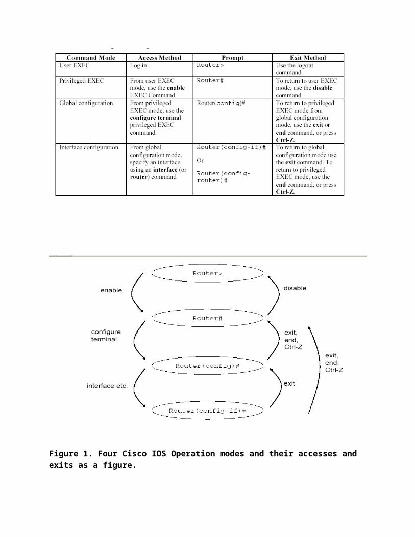
Cisco Inter-network Operating System (IOS) Cisco IOS Operation ModesThe Cisco Software provides access to four different command modes. There are morecommands, but in normal use they are not necessary. Each command mode provides adifferent group of related commands. For security purposes, the Cisco IOS softwareprovides two levels of access to commands: user and privileged. The unprivileged user
mode is called user EXEC mode. The privileged mode is called privileged EXEC modeand requires a password.The following table, Table (1) describes four used modes, how to enter the modes andthe resulting prompts. The prompt helps you identify which mode you are in andtherefore which commands are available to you. In Fig. (1) these four operation modesare presented as a figure.

Figure 1. Four Cisco IOS Operation modes and their accesses and exits as a figure.
User EXEC ModeWhen you are connected to the router, you are started in user EXEC mode. The userEXEC commands are a subset of the privileged EXEC commands.
Privileged EXEC ModePrivileged commands include the following:Configure – Changes the software configuration.Debug – Display process and hardware event messages.Setup – Enter configuration information at the prompts.Enter the command disable to exit from the privileged EXEC mode and return to userEXEC mode.Configuration ModeConfiguration mode has a set of submodes that you use for modifying interfacesettings, routing protocol settings, line settings, and so forth. Use caution withconfiguration mode because all changes you enter take effect immediately.To enter configuration mode, enter the command configure terminal and exit bypressing Ctrl-Z.No FormAlmost every configuration command also has a no form. In general, use the no form todisable a feature or function. Use the command without the keyword no to re-enable adisabled feature or to enable a feature that is disabled by default. For example, IP

routing is enabled by default. To disable IP routing, enter the no ip routing commandand enter ip routing to re-enable it.Getting HelpIn any command mode, you can get a list of available commands by entering a questionmark (?).Router>?To obtain a list of command that begin with a particular character sequence, type inthose characters followed immediately by the question mark (?).Router#co?Configure connect copyTo list keywords or arguments, enter a question mark in place of a keyword orargument. Include a space before the question mark.Router#configure ?memory Configure from NV memorynetwork Configure from a TFTP network hostterminal Configure from the terminalYou can also abbreviate commands and keywords by entering just enough characters tomake the command unique from other commands. For example, you can abbreviate theshow command to sh.
Configuration FilesAny time you make changes to the router configuration, you must save the changes tomemory because if you do not they will be lost if there is a system reload or poweroutage. There are two types of configuration files: the running (current operating)configuration and the startup configuration, which is loaded up in rebooting a router.Use the following privileged mode commands to work with configuration files.configure terminal – modify the running configuration manually from theterminal.show running-config – display the running configuration.show startup-config – display the startup configuration.copy running-config startup-config – copy the running configuration to thestartup configuration.copy startup-config running-config – copy the startup configuration to therunning configuration.erase startup-config – erase the startup-configuration in NVRAM.copy tftp running-config – load a configuration file stored on a Trivial FileTransfer Protocol (TFTP) server into the running configuration.copy running-config tftp – store the running configuration on a TFTP server.
Configuration System (Setup)In privileged EXEC mode you can setup the whole system, for example setup networkcards, put IP addresses, start simple RIP routing.Router#setupIn Cisco routers interfaces are named as FastEthernet0/0 and FastEthernet0/1. Some ofour lab routers also include serial cable interfaces. Numbering is same like above.
Address and Interface ConfigurationIf you don’t like to put IP address like in 1.4 Configuration System (Setup), you can putthem with the following instructions.In privileged EXEC mode give the next command:Router#config terminalThen enter the interface type port to enter the interface configuration mode.Router(config)#interface FastEthernet0/0Now you are in interface configuration mode and you can modify this chosen interface.Enter the IP address and subnet mask of the interface using ip address ipaddresssubnetmask command.Router(config-if)#ip address 10.12.0.1 255.255.255.252In this mode you can give parameters like for example hello protocol interval in OSPFfor an interface. Exit interface configuration mode by giving command Ctrl-Z.
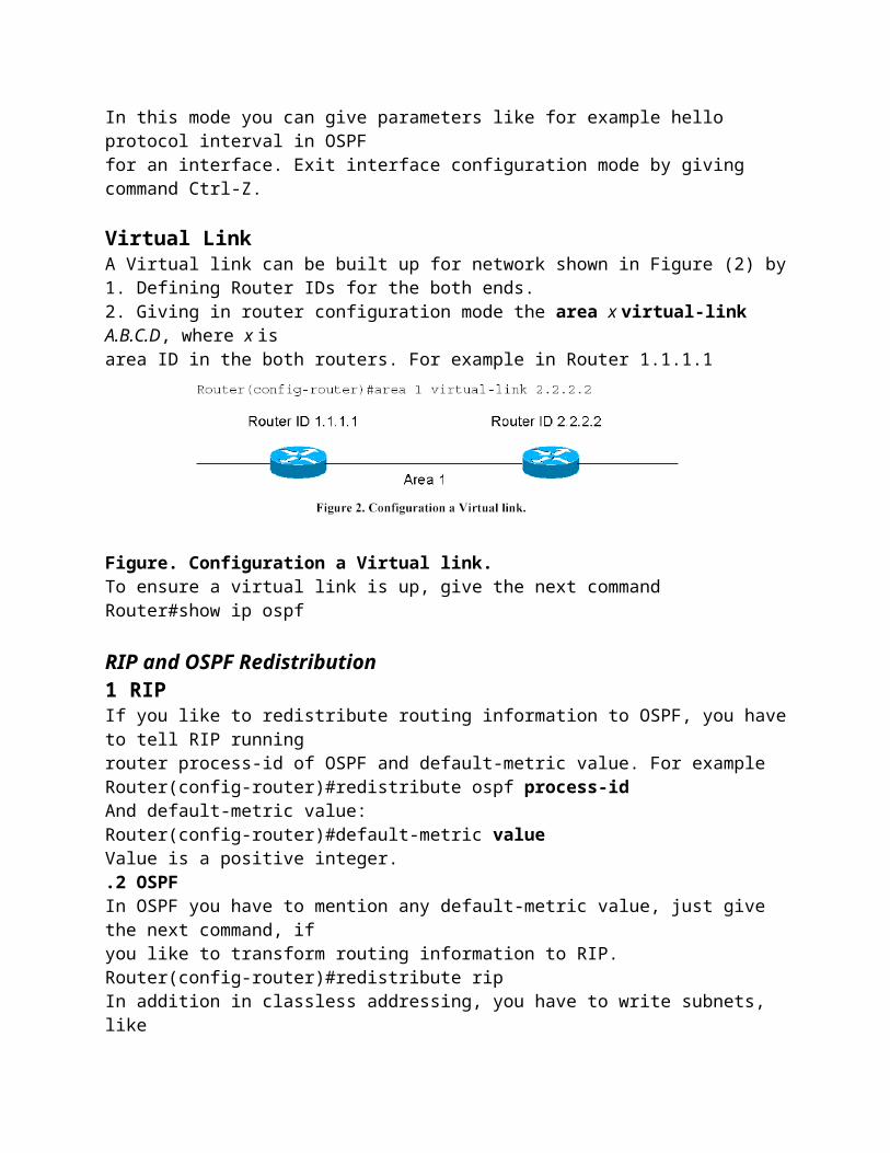
Virtual LinkA Virtual link can be built up for network shown in Figure (2) by1. Defining Router IDs for the both ends.2. Giving in router configuration mode the area x virtual-link A.B.C.D, where x isarea ID in the both routers. For example in Router 1.1.1.1
Figure. Configuration a Virtual link.To ensure a virtual link is up, give the next commandRouter#show ip ospf
RIP and OSPF Redistribution1 RIPIf you like to redistribute routing information to OSPF, you have to tell RIP runningrouter process-id of OSPF and default-metric value. For example

Router(config-router)#redistribute ospf process-idAnd default-metric value:Router(config-router)#default-metric valueValue is a positive integer..2 OSPFIn OSPF you have to mention any default-metric value, just give the next command, ifyou like to transform routing information to RIP.Router(config-router)#redistribute ripIn addition in classless addressing, you have to write subnets, likeRouter(config-router)#redistribute rip subnets3 GatewayWhen you have a network with running a routing protocol and you like to connect it toanother network running B routing protocol throughout one or more routers, you haveto tell about border area router or gateway router with the following command. Bnetwork is generally much bigger and for example the Internet.Router(config-router)#default-information originate4 LANIf a LAN is connected to a router as shown in Fig. 3., you have to tell about it to therouter’s routing protocol. Just writeRouter(config-router)#redistribute connectedLAN
Access Control List

Traffic filtering controls the flow of data across a network. By separating out transmissions through a router, network traffic can be limited to reduce bandwidth consumption by unnecessary protocol traffic, traffic flow can be managed, and certain users or devices can be restricted from accessing network segments or network services for security purposes. Filtering is performed on Cisco routers through the use of access lists.
Access List:- An access list will dictate whether routed packets are blocked at a router’s interfaceOr forwarded to its destination. Routers check each routed packet to determine whether it is to continue on its current segment or if it is to be forwarded, and then where toForward it to.
The router will base a “forward or drop” decision on the conditions in the access list. These conditions can include:
Source address Destination address The protocol being used Other information, which is dependent on the access list and protocol types
Access lists can be used for many things:- Controlling the transmission of packets across an interface, restricting traffic across virtual terminal lines, or restricting routing updates. Each list is a series of “permit” or “deny” statements about the type of traffic you wish to filter, and a unique number identifies the access list. Each’ permit’ and ‘deny’ statement within a single list must have the same number, and must be on a separate line of the configuration. The number must fall within the ranges listed in Table depending on what service you are applying the access list to.
Extended IP Access Lists Extended IP access lists allow you to control traffic at a more granular level than the standard IP access lists. Extended IP access lists can use both the source and destination IP addresses when it tries to match up packets to the list. This feature can effectivelyBlock traffic between two specific hosts, but enable each host to access other services on the segments. Additionally other options exist for filtering the traffic. Some of these are protocol number filtering within the IP header and port number filtering at theTransport layer. All of the rules learned from standard IP apply in Extended IP. A few of them are as follows:-
One cannot selectively add to a numeric access list. Named access lists allow you to selectively remove lines.
New lines are always placed at the bottom of the list and are then executed sequentially after any previous lines.
The access list itself does nothing. It must be applied it to an interface to be used. By default, at the end of every access list is an implicit “deny any” statement.
Remove all Access Lists from the Router’s Configuration:-Complete the following steps to properly remove all configured access lists from your
router.
Enter interface configuration mode by typing the Following command:
Router#(config) interface ethernet 0 Remove access-lists 1 and 101 from the interface by entering these commands:

Router#(config-int) no ip access-group 1 in Router#(config-int) no ip access-group 101 in
Now that the access-lists are removed from the interface, you can safely remove them from the global configuration by entering the following commands:
Router#(config) no access-list 1 Router#(config) no access-list 101
Extended IP Access ListsIn the standard IP access list example, notice how you had to block the whole
subnet from getting to the finance department. What if you wanted them togain access to only a certain server on the Finance LAN, but not to other networkservices, for obvious security reasons? With a standard IP access list,you can’t allow users to get to one network service and not another. However,extended IP access lists allow you to do this. Extended IP access listsallow you to choose your IP source and destination address as well as theprotocol and port number, which identify the upper-layer protocol or application.By using extended IP access lists, you can effectively allow usersaccess to a physical LAN and stop them from using certain services.Here is an example of an extended IP access list. The first command showsthe access list numbers available. You’ll use the extended access list rangefrom 100 to 199.
RouterA(config)#access-list ?<1-99> IP standard access list<100-199> IP extended access list<1000-1099> IPX SAP access list<1100-1199> Extended 48-bit MAC address access list<1200-1299> IPX summary address access list<200-299> Protocol type-code access list<300-399> DECnet access list<400-499> XNS standard access list<500-599> XNS extended access list<600-699> Appletalk access list<700-799> 48-bit MAC address access list<800-899> IPX standard access list<900-999> IPX extended access listAt this point, you need to decide what type of list entry you are making.For this example, you’ll choose a deny list entry.
RouterA(config)#access-list 110 ?deny Specify packetdynamic Specify a DYNAMIC list of PERMITs or DENYs

Once you choose the access list type, you must choose a Network layerprotocol field entry. It is important to understand that if you want to filterthe network by Application layer, you must choose an entry here that allowsyou to go up through the OSI model. For example, to filter by Telnet or FTP,you must choose TCP here. If you were to choose IP, you would never leavethe Network layer, and you would not be allowed to filter by upper-layerapplications.
RouterA(config)#access-list 110 deny ?<0-255> An IP protocol numbereigrp Cisco's EIGRP routing protocolgre Cisco's GRE tunnelingicmp Internet Control Message Protocoligmp Internet Gateway Message Protocoligrp Cisco's IGRP routing protocolip Any Internet Protocolipinip IP in IP tunnelingnos KA9Q NOS compatible IP over IP tunnelingospf OSPF routing protocoltcp Transmission Control Protocoludp User Datagram ProtocolOnce you choose to go up to the Application layer through TCP, you willbe prompted for the source IP address of the host or network. You canchoose the any command to allow any source address.RouterA(config)#access-list 110 deny tcp ?A.B.C.D Source addressany Any source hosthost A single source hostAfter the source address is selected, the destination address is chosen.RouterA(config)#access-list 110 deny tcp any ?A.B.C.D Destination addressany Any destination hosteq Match only packets on a given port numbergt Match only packets with a greater port numberhost A single destination host
lt Match only packets with a lower port numberneq Match only packets not on a given port numberrange Match only packets in the range of port numbersIn the example below, any source IP address that has a destination IPaddress of 172.16.30.2 has been denied.
RouterA(config)#access-list 110 deny tcp any host172.16.30.2 ?

eq Match only packets on a given port numberestablished Match established connectionsfragments Check fragmentsgt Match only packets with a greater portnumberlog Log matches against this entrylog-input Log matches against this entry,includinginputinterfacelt Match only packets with a lower port numberneq Match only packets not on a given portnumberprecedence Match packets with given precedence valuerange Match only packets in the range of portnumberstos Match packets with given TOS value<cr>
Now, you can press Enter here and leave the access list as is. However,you can be even more specific: once you have the host addresses in place, youcan specify the type of service you are denying. The following help screengives you the options. You can choose a port number or use the applicationor even the program name.RouterA(config)#access-list 110 deny tcp any host172.16.30.2 eq ?<0-65535> Port numberbgp Border Gateway Protocol (179)chargen Character generator (19)cmd Remote commands (rcmd, 514)daytime Daytime (13)
Extended IP Access List Example
Using Figure 9.1 from the IP standard access list example again, let’s use thesame network and deny access to a server on the finance-department LANfor both Telnet and FTP services on server 172.16.10.5. All other services onthe LAN are acceptable for the sales and marketing departments to access.The following access list should be created:Acme#config tAcme(config)#access-list 110 deny tcp any host 172.16.10.5 eq 21Acme(config)#access-list 110 deny tcp any host 172.16.10.5 eq 23Acme(config)#access-list 110 permit ip any any
It is important to understand why the denies were placed first in the list.This is because if you had configured the permits first and the denies second,the Finance LAN would have not been able to go to any other LAN or to theInternet because of the implicit deny at the end of the list. It would be difficultto configure the list any other way than the preceding example.After the lists are created, they need to be applied to the Ethernet 0 port.This is because the other three interfaces on the router need access to the

Virtual Local Area Network (VLAN)
AVirtual Local Area Network (VLAN) is a logical groupingof network users and resources connected to administratively defined portson a switch. By creating VLANs, you are able to create smaller broadcastdomains within a switch by assigning different ports in the switch to differentsubnetworks. A VLAN is treated like its own subnet or broadcastdomain. This means that frames broadcasted onto a network are only
Virtual LANs
n a layer-2 switched network, the network is flat, as shown in Figure6.1. Every broadcast packet transmitted is seen by every device on the network,regardless of whether the device needs to receive the data.
FIGURE 6 . 1Flat network structure

for each device plugged into the switch, the Ethernet distance constraints arelifted, which means larger networks can be built. The larger the number ofusers and devices, the more broadcasts and packets each device must handle.Another problem with a flat layer-2 network is security, as all users cansee all devices. You cannot stop devices from broadcasting and users tryingto respond to broadcasts. Your security is passwords on the servers andother devices.By creating VLANs, you can solve many of the problems associated withlayer-2 switching, as shown in the upcoming sections.
Broadcast Control
Broadcasts occur in every protocol, but how often they occur depends uponthe protocol, the application(s) running on the internetwork, and how theseservices are used.Some older applications have been rewritten to reduce their bandwidthneeds. However, there is a new generation of applications that are bandwidthgreedy,consuming all they can find. These are multimedia applications thatuse broadcasts and multicasts extensively. Faulty equipment, inadequatesegmentation, and poorly designed firewalls can also add to the problemsof broadcast-intensive applications. This has added a new chapter to networkdesign, since broadcasts can propagate through the switched network.Routers, by default, send broadcasts only within the originating network,3 1 4 2• Each segment has its own collision domain.• All segments are in the same broadcast domain.
but switches forward broadcasts to all segments. This is called aflat networkbecause it is one broadcast domain.As an administrator, you must make sure the network is properly segmentedto keep one segment’s problems from propagating through the internetwork.The most effective way of doing this is through switching androuting. Since switches have become more cost-effective, many companiesare replacing the flat network with a pure switched network and VLANs. Alldevices in a VLAN are members of the same broadcast domain and receiveall broadcasts. The broadcasts, by default, are filtered from all ports on aswitch that are not members of the same VLAN.Routers, layer-3 switches, or route switch modules (RSMs) must be usedin conjunction with switches to provide connections between networks(VLANs), which can stop broadcasts from propagating through the entireinternetwork.

SecurityOne problem with the flat internetwork is that security was implemented byconnecting hubs and switches together with routers. Security was maintainedat the router, but anyone connecting to the physical network couldaccess the network resources on that physical LAN. Also, a user could pluga network analyzer into the hub and see all the traffic in that network.Another problem was that users could join a workgroup by just pluggingtheir workstations into the existing hub.By using VLANs and creating multiple broadcast groups, administratorsnow have control over each port and user. Users can no longer just plug theirworkstations into any switch port and have access to network resources. Theadministrator controls each port and whatever resources it is allowed to use.Because groups can be created according to the network resources a userrequires, switches can be configured to inform a network management stationof any unauthorized access to network resources. If inter-VLAN communicationneeds to take place, restrictions on a router can also beimplemented. Restrictions can also be placed on hardware addresses, protocols,and applications.
Flexibility and ScalabilityLayer-2 switches only read frames for filtering; they do not look at the Networklayer protocol. This can cause a switch to forward all broadcasts.However, by creating VLANs, you are essentially creating broadcastdomains. Broadcasts sent out from a node in one VLAN will not be forwardedto ports configured in a different VLAN. By assigning switch portsor users to VLAN groups on a switch or group of connected switches (called aswitch fabric), you have the flexibility to add only the users you want in thebroadcast domain regardless of their physical location. This can stop broadcaststorms caused by a faulty network interface card (NIC) or an applicationfrom propagating throughout the entire internetwork.When a VLAN gets too big, you can create more VLANs to keep thebroadcasts from consuming too much bandwidth. The fewer users in aVLAN, the fewer users affected by broadcasts.To understand how a VLAN looks to a switch, it’s helpful to begin by firstlooking at a traditional collapsed backbone. Figure 6.2 shows a collapsedbackbone created by connecting physical LANs to a router.
FIGURE Physical LANs connected to a router
Each network is attached to the router and has its own logical networknumber. Each node attached to a particular physical network must matchthat network number to be able to communicate on the internetwork. Nowlet’s look at what a switch accomplishes. Figure 6.3 shows how switchesremove the physical boundary.Net = ANet = CNet = B Net = DFIGURE

Switches removing the physical boundary
Switches create greater flexibility and scalability than routers can bythemselves. You can group users into communities of interest, which areknown as VLAN organizations.Because of switches, we don’t need routers anymore, right? Wrong. InFigure 6.3, notice that there are four VLANs or broadcast domains. Thenodes within each VLAN can communicate with each other, but not withany other VLAN or node in another VLAN. When configured in a VLAN,the nodes think they are actually in a collapsed backbone as in Figure 6.2.What do the hosts in Figure 6.2 need to do to communicate to a node or hoston a different network? They need to go through the router, or other layer-3 device, just like when they are configured for VLAN communication, asshown in Figure 6.3. Communication between VLANs, just as in physicalnetworks, must go through a layer-3 device.
VLAN MembershipsVLANs are typically created by an administrator, who then assigns
switch ports to the VLAN. These are called static VLANs. If the administratorwants to do a little more work up front and assign all the host devices’hardware addresses into a database, the switches can be configured to assignVLANs dynamically.
Static VLANs
Static VLANsare the typical way of creating VLANs and the most secure.The switch port that you assign a VLAN association always maintains thatassociation until an administrator changes the port assignment. This type ofVLAN configuration is easy to set up and monitor, working well in a networkwhere the movement of users within the network is controlled. Usingnetwork management software to configure the ports can be helpful but isnot mandatory.
Dynamic VLANsDynamic VLANsdetermine a node’s VLAN assignment automatically.Using intelligent management software, you can enable hardware (MAC)addresses, protocols, or even applications to create dynamic VLANs. Forexample, suppose MAC addresses have been entered into a centralizedVLAN management application. If a node is then attached to an unassignedswitch port, the VLAN management database can look up the hardware

address and assign and configure the switch port to the correct VLAN. Thiscan make management and configuration easier for the administrator. If auser moves, the switch will automatically assign them to the correct VLAN.However, more administration is needed initially to set up the database.Cisco administrators can use the VLAN Management Policy Server(VMPS) service to set up a database of MAC addresses that can be used fordynamic addressing of VLANs. VMPS is a MAC address–to–VLAN mappingdatabase.
connecting switches together, trunk links can carry some or all VLAN informationacross the link. If you do not trunk these links between switches, thenthe switches will only send VLAN 1 information by default across the link.All VLANs are configured on a trunked link unless cleared by an administratorby hand.Cisco switches use the Dynamic Trunking Protocol (DTP) to managetrunk negation in the Catalyst-switch engine software release 4.2 or later,using either ISL or 802.1q. DTP is a point-to-point protocol that was createdto send trunk information across 802.1q trunks.
Routing between VLANs
Hosts in a VLAN are within their own broadcast domain and communicatefreely. VLANs create network partitioning and traffic separationat layer 2 of the OSI specifications. To have hosts or any device communicatebetween VLANs, a layer-3 device is absolutely necessary.You can use a router that has an interface for each VLAN, or a router thatsupports ISL routing. The least expensive router that supports ISL routing isthe 2600 series router. The 1600, 1700, and 2500 series do not support ISLrouting.If you only had a few VLANs (two or three), you could get a router withtwo or three 10BaseT or FastEthernet connections. 10BaseT is OK, butFastEthernet will work really well.However, if you have more VLANs available than router interfaces, youcan either run ISL routing on one FastEthernet interface or buy a routeswitch module (RSM) for a 5000 series switch. The RSM can support up to1005 VLANs and run on the backplane of the switch. If you use one Fast-Ethernet interface and run ISL routing, Cisco calls this a router-on-a-stick.

VLAN Trunk Protocol (VTP)
Cisco createdVLAN Trunk Protocol (VTP)to manage all the configuredVLANs across a switched internetwork and to maintain consistencythroughout the network. VTP allows an administrator to add, delete,and rename VLANs, which are then propagated to all switches.
VTP provides the following benefits to a switched network:_Consistent VLAN configuration across all switches in the network_Allowing VLANs to be trunked over mixed networks, like Ethernet toATM LANE or FDDI_Accurate tracking and monitoring of VLANs_Dynamic reporting of added VLANs to all switches_Plug-and-Play VLAN addingTo allow VTP to manage your VLANs across the network, you must firstcreate a VTP server. All servers that need to share VLAN information mustuse the same domain name, and a switch can only be in one domain at a time.This means that a switch can only share VTP domain information withswitches configured in the same VTP domain.A VTP domain can be used if you have more than one switch connectedin a network. If all switches in your network are in only one VLAN, then youdon’t need to use VTP. VTP information is sent between switches via a trunkport.Switches advertise VTP-management domain information, as well as aconfiguration revision number and all known VLANs with any specificparameters. You can configure switches to forward VTP informationthrough trunk ports but not accept information updates, nor update theirVTP database. This is called VTP transparent mode.If you are having problems with users adding switches to your VTPdomain, you can add passwords, but remember that every switch must be setup with the same password, which may be difficult.Switches detect the additional VLANs within a VTP advertisement andthen prepare to receive information on their trunk ports with the newlydefined VLAN in tow. The information would be VLAN ID, 802.10 SAIDfields, or LANE information. Updates are sent out as revision numbers thatare the notification plus 1. Anytime a switch sees a higher revision number,

it knows the information it is receiving is more current and will overwrite thecurrent database with the new one.
VTP Modes of OperationThere are three different modes of operation within a VTP domain. Figure 6.4shows all three.FIGURE 6 . 4
ServerIs the default for all Catalyst switches. You need at least one
server in your VTP domain to propagate VLAN information throughoutthe domain. The switch must be in server mode to be able to create, add,or delete VLANs in a VTP domain. Changing VTP information must alsobe done in server mode. Any change made to a switch in server mode isadvertised to the entire VTP domain.
ClientReceives information from VTP servers and send and receives
updates, but cannot make any changes. No ports on a client switch can beadded to a new VLAN before the VTP server notifies the client switch ofthe new VLAN. If you want a switch to become a server, first make it aclient so it receives all the correct VLAN information, then change it to aserver.

TransparentDoes not participate in the VTP domain but will still forward
VTP advertisements through the configured trunk links. VTP transparentswitches can add and delete VLANs as the switch keeps its owndatabase and does not share it with other switches. Transparent is consideredonly locally significant.

NAT/PAT
Network address translation(NAT):- In computer networking, network address translation (NAT) is the process of modifying network address information in datagram (IP) packet headers while in transit across a traffic routing device for the purpose of remapping one IP address space into another.
In the mid-1990s NAT became a popular tool for alleviating the problem of IPv4 address exhaustion. It has become a standard, indispensable feature in routers for home and small-office Internet connections.
Most systems using NAT do so in order to enable multiple hosts on a private network to access the Internet using a single public IP address (see gateway). However, NAT breaks the originally envisioned model of IP end-to-end connectivity across the Internet, introduces complications in communication between hosts, and affects performance.
NAT obscures an internal network's structure: all traffic appears to outside parties as if it originated from the gateway machine.
Network address translation involves over-writing the source or destination IP address and usually also the TCP/UDP port numbers of IP packets as they pass through the router. Checksums (both IP and TCP/UDP) must also be rewritten as a result of these changes.

Static and Dynamic NAT:-
Static NAT :- It maps a single private network address, which is typically the address of a network server, to a single public network address. Static NAT allows hosts outside of the private network to use a public IP address to access hosts on a private network. Static NAT is a potential security risk. If the network security policy is configured incorrectly, the private network device mapped to the public IP address might be fully exposed to the public network.
Dynamic NAT :- It is a type of Hide NAT that uses different network source ports to map multipleprivate addresses to a single public address. This type of address mapping is also known as:
IP masquerading Port address translation Single address NAT Port-level multiplexed NAT
Regardless of the name, in this type of address mapping, the mapping is not static. In hide NAT,for each session between an internal network device and the public network, the public IP address remains the same, but the source port for each device changes.
Port Addresses Translation(PAT):-
Port Address Translation (PAT) is a feature of a network device that translates TCP or UDP communications made between hosts on a private network and hosts on a public network. It allows a single public IP address to be used by many hosts on a private network, which is usually a Local Area Network or LAN.
A PAT device transparently modifies IP packets as they pass through it. The modifications make all the packets which it sends to the public network from the multiple hosts on the private network appear to originate from a single host, (the PAT device) on the public network.
PAT is a subset of NAT, and is closely related to the concept of Network Address Translation. PAT is also known as NAT Overload. In PAT there is generally only one publicly exposed IP address and multiple private hosts connecting through the exposed address.
Incoming packets from the public network are routed to their destinations on the private network by reference to a table held within the PAT device which keeps track of public and private port pairs.