xd1-t transformer differential protection relay tb xd1-t 08.96 e contents 1. application and...
TRANSCRIPT

XD1-T - Transformer differential protection relay

2 TB XD1-T 08.96 E
Contents
1. Application and features
2. Design
3. Characteristics3.1 Operating principle of the differential
protection3.2 Balancing of phases and current
amplitudes3.3 Transformer regulation steps3.4 Working principle of the C.T.
saturation detector SAT3.5 Transformer inrush3.6 Block diagram
4. Operation and Settings4.1 Parameter setting by using DIP-switches4.2 Setting recommendations
5. Relay testing and commissioning5.1 Power on5.2 Secondary injection test5.2.1 Trip level Id1
5.2.2 Inrush blocking5.3 Primary test5.3.1 Adjustment of the interposing C.T.s5.3.2 Function test
6. Relay Housing and technical Data6.1 Relay housing6.2 Technical data
7. Order Form
1. Application and features
Power transformers are classified as one of the mostvaluable equipments in a power system, hence theirprotection is of very high importance. The transformerdifferential protection provides fast tripping in case ofa fault - before severe damage spreads out.
The XD1-T relay is a strict selective object protectionfor two-winding transformers. Within a very short timethis relay detects faults occuring within the zone to beprotected and which require immediate tripping andisolation of the transformer. Such faults are:
• short circuits between turns, windings and cables in-side the transformer housing
• earth faults inside the housing• short circuits and earth faults outside the housing but
within the protected zone (e.g. at bushings or supplylines).
The XD1-T is also able to detect other operationalconditions (e.g. faults outside the protected zone, cir-cuit closing etc.) i.e. it does not issue tripping com-mands for faults or any other transient phenomena out-side the protected zone.
Additional to the transformer differential protection anovercurrent relay as backup protection is recom-mended. For this application we offer the relaysMRI1/IRI1/XI1.
The relay XD1-T of the PROFESSIONAL LINE has the fol-lowing special features:• Fault indication via LEDs• Extremely wide operating ranges of the supply volt-
age by universal wide-range power supply• Very fine graded wide setting ranges• Extremely short response time• Compact design by SMD-technology• Very low C.T. burden• Adjustment to transformation ratio and connection
groups without external interposing C.T.s• Two stage tripping characteristic• Galvanic insulation between all independent inputs• Additional printed circuits "Saturation Detection" can
be retrofitted at a later time• Self-supervision of stabilization circuits• Wide setting ranges

TB XD1-T 08.96 E 3
2. Design
Fig. 2.1: Connection diagram
Analog inputs
The analog secondary currents of the HV side are fedto the protection relay via terminals 1S1 - 3S2 andthe secondary currents of the LV side via terminals4S1 - 6S2.
Auxiliary voltage supply
Unit XD1-T needs a separate auxiliary voltage supply.Therefore a DC or AC voltage must be used.Unit XD1-T has an integrated wide range powersupply. Voltages in the range from 19 - 390 V DC or36 - 275 V AC can be applied at connection termi-nals A1 and A2.
Contact positions
Operation without faultor dead conditions
Contact positions aftertripping
Fig 2.2: Contact positions of the output relays

4 TB XD1-T 08.96 E
3. Working Principle
3.1 Operating principle of the differen-tial protection
The fundamental operating principle of transformer dif-ferential protection is based on comparison of thetransformer primary and secondary winding currents.For an ideal transformer, having a 1:1 ratio and ne-glecting magnetizing current, the currents entering andleaving the transformer must be equal.
During normal operation or when a short circuit hasoccured outside the protected zone, the C.T. secon-dary currents in the differential circuit neutralize eachother. In case that a differential current Id occurs, afault in the transformer is detected.
I1 I2
Iin Iout
Transformer
Currentcomparision
Id
I
UU
s
s
d
Biasing circuit
Trippingcharacteristic
Trip
Differential relay
Protected Zone
Fig. 3.1: General arrangement of differential protection:Id = differential (tripping) currentIs = stabilizing current
Because of different problems, however, in practicemeasures for adaption and stabilization have to betaken to ensure trouble-free function of the transformerdifferential protection:• Due to possible mismatch of ratios among different
current transformers.• Phase differences between primary and secondary
side, caused by transformer vector groups, have tobe duly considered.
• Switching operations in the grid have to be recogni-zed as such.
• Inrush currents of the transformer must not result inmaloperation.
3.2 Balancing of phases and currentamplitudes
First of all the phase difference between primary andsecondary side, which is caused by transformer vectorgroups, has to be compensated and the current ampli-tudes to be balanced. Unlike most other differentialprotection relays available, this scheme includes inter-posing C.T.s integrated in the differential relay, extrainterposing C.T.s are not required.
Connection of interposing C.T.s is dependent on thevector group of the power transformer. For instance,for transformers with star (Y) windings the interposingC.T.s are connected in delta (∆) to reject residual cur-rents (i.e. currents flowing to the transformer due to anearth fault outside the protected zone and whichwould produce a differential current Id) and to preventmaloperation of the differential protection.

TB XD1-T 08.96 E 5
3.3 Transformer regulation steps
The XD1-T can universally be used i.e. also for regulat-ing transformers with an adjustable transformation ratioto stabilize voltage fluctuations of the supplying sys-tems. Since, however, as a result of vector group bal-ance and transformation ratio balance the differentialprotection is adjusted to the nominal transformation ra-tio of the transformer, an apparent differential current Idarises proportionally to the flowing load current.Maloperation of the protection is prevented by theload-proportional stabilizing current IS.
3.4 Working principle of the C.T.saturation detector SAT
With many transformer differential protection systems,relay instability may cause to trip if the main currenttransformers saturate. In the transient condition of satu-ration the C.T.s on both ends of the protected zonesdo not produce the correct secondary current accord-ing to the primary current. The differential relay meas-ures a differential current on the secondary C.T. sidewhich is not present on the primary side. Hence a nui-sance tripping might occure.
Such transient phenomenons causing C.T. saturationmay occur due to:• Heavy through faults (external short circuit)• Starting of big motors• Magnetizing inrush currents of transformers• Internal faults
The figure 3.2 explains the saturation of the C.T. coredue to a short circuit current. In the instant of a shortcircuit often a DC-component is present in the current.The high primary current induces a flux in the C.T.core, reaching the saturation level. The iron-core re-tains the high flux level even after the primary currentfalls to zero. In the time periods of saturation the C.T.does not transform the primary current to the secondaryside but the secondary current equals zero.
Fig. 3.2 Current transformer saturationa) Primary current with DC offsetb) Core flux densityc) Secondary current

6 TB XD1-T 08.96 E
Dissimilar saturation in any differential scheme willproduce operating current.
Figure 3.3 shows the differential measurement on theexample of extremly dissimilar saturation of C.T.s in adifferential scheme. Fig. 3.3 shows the secondary cur-rent due to C.T. saturation during an transformer fault(internal fault). The differential current id represents thefault current. The differential relay must trip instanta-nously.
Fig. 3.3 shows the two secondary currents in the in-stant of an heavy external fault, with current i1 sup-posed to C.T. saturation, current i2 without C.T. satura-tion.
The differential current id represents the measured dif-ferential current, which is an operating current. As thisdifferential current is caused by an external fault anddissimilar saturation of the two C.T.s, the differential re-lay should not trip.
Left Single end fed: i1 = secondary output current from saturated C.T. (theroretical)i2 = 0; Internal fault fed from side 1 onlyid = measured differential current
Right External fault: i1 as in fig. 3.3 for an internal faulti2 normal current from C.T. secondary on side 2The wave forms for the differential current Id for internal and externalfaults are seen to be different for the two cases considered.
i1, i2
t
i1 i2=0
id
t
id=i2-i1
i1, i2
t
i1 i2
id
t
id=i2-i1
Fig. 3.3: Current comparison with C.T.s saturated by DC offset in fault current wave form internal fault

TB XD1-T 08.96 E 7
The saturation detector SAT analyses the differentialcurrent of each phase separately. The SAT module dif-ferentiates the differential current and detects:
• Rate of change of differential current d(id)/dt• Sign of d(id)/dt• Internal / external fault• Duration of saturation, within one cycle• DC or AC saturation
The instant of an extreme rate of change of differentialcurrent d(id)/dt clearly marks the beginning of a C.T.saturation.The sign of this d(id)/dt value distinguishes the internalfault from an external fault.One detected extreme d(id)/dt value per cycle indi-cates a saturation due to DC-current contents.Whereas two extreme d(id)/dt values per cycle indi-cate a C.T. saturation caused by a high alternatingcurrent.
The logic control evaluating above informations de-rives.
Only external faults lead to blocking of the trip circuit:• In case of detected DC-current saturation the differen-
tial current measurement is blocked completelyuntil: the transient condition ends, or an internal faultis detected (instantanously), or AC-current saturationis detected.
• In case of detected AC-current saturation only thetime periods of saturation are blocked during onecycle. This means that even under severe saturationthe differential relay evaluates the differential currentin "sound“ time periods. This is a major advantageto relays solely applying harmonic filters for satura-tion detecting.
• All detected transient phenomenons change the trip-ping characteristic to the "coarse tripping character-istic" (pl. ref. to Technical Data).
This logic control circuit provides a continuous self di-agnostic, limiting any blocking function to maximum of1.7 seconds.
This approach has several advantages. For example,if a C.T. saturated as a result of an external fault, therelay remains stable because the measuring systemrecognizes the differential current is due to C.T. satura-tion arising from a fault outside the protected zone.However, if an internal fault occurs, this is immediatelyrecognized, blocking is overridden and the relay tripsimmediately.
Similarly, if a fault occurs during magnetizing inrush ofa transformer this is immediately detected and the dif-ferential relay operates correctly tripping the trans-former.

8 TB XD1-T 08.96 E
3.5 Transformer inrush
When a transformer is first energized, a transient in-rush current flows. This inrush current occurs only in theenergized winding and has no equivalent on the otherside of the transformer. The full amount of inrush currentappears as differential current and would cause thedifferential relay to trip if there is no stabilisationagainst the inrush phenomenon.
Typically the inrush current contains three componentsthat distinguish it from other fault currents:
The DC-component:The DC-component is present at least in one phase of the inrush current, depending on the instant of energizing.
The second harmonic:The second harmonic is present in all inrush currents due to uni-directional flux in the transformer core.
The fifth harmonic:The fifth harmonic is present when the transformer is subjected to a temporary overvoltage.
The filter module "SAT" detects not only C.T. saturationdue to external faults but also the inrush current of thetransformer to be protected.
The differential current id of each phase is analysedseparately. The signal of id passes a filter arrangementdetecting transient conditions due to the DC-component, the second harmonic and the fifth har-monic.
Thus all three components are used for detecting an in-rush current. The limits for blocking of the differentialprotection are:
DC-component: 20%...60% of id2nd harmonic: 20%...50% of id5th harmonic: 10%...25% of id
The restraining influence, resp. the blocking dependson the combination of the three components. If only asingle component is present, the highest value applies.If a mixture of all three components is present, thelowest values apply.
With this combined measurement of the three restrain-ing components XD1-T achieves:
• Reliable inrush stabilisation• Fast tripping if the incoming transformer is defective• Restraining feature against C.T.-saturation.
Whereas a complete blocking of the protection is onlyperformed during the first energizing of the transformer,the harmonic content supervision restrains during nor-mal operation against phenomenons like C.T. satura-tion. This means that internal faults will be detected in-stantaneously (ms), whereas external faults do notcause tripping.
The inrush blocking is stopped when:
• The differential current Id falls below the tripping cha-racteristic, or
• the differential current Id shows an internal fault, ac-cording to the harmonic content, or
• the differential current Id exceeds 15 x nominal cur-rent, or
• a fixed period of time has elapsed.
The basic relay version without module "SAT" doesnot provide the harmonic restrain feature.
For applications on bigger transformers or for genera-tor-transformer protection we recommend the use ofmodule "SAT".

TB XD1-T 08.96 E 9
3.6 Block diagram
Fig. 3.4: Block diagram

10 TB XD1-T 08.96 E
4. Operation and settings
All operating elements needed for setting parametersare located on the front plate of the XD1-T as well asall display elements.Because of this all adjustments of the unit can be madeor changed without disconnecting the unit off the DIN-rail.
Fig 4.1 Front plate XD1-T
For adjustment of the unit the transparent cover has tobe opened as illustrated. Do not use force! The trans-parent cover has two inserts for labels.
Fig. 4.2: How to open the transparent cover
LEDs
LED „ON“ is used for display of the readiness for ser-vice (at applied auxiliary voltage Uv). LEDs L1, L2, L3and TRIP are provided for fault indication. LED ∆2/OOindicates inrush stabilization. For relays with an addi-tional SAT module, changeover to the coarse measu-ring element is indicated
Reset push-button
The Reset push-button is used for acknowledgementand resetting the LEDs after tripping.
Potentiometer
The 3 potentiometer on the lower right side of the frontplate are provided for adjustment of the interposingC.T.s (refer to chapter 5.3.1).

TB XD1-T 08.96 E 11
4.1 Parameter setting by usingDIP-switches
The XD1-T provides two DIP-switches for the adjust-ment of the tripping characteristic:
Id1 represents the setting for the tripping area belownominal current. The Id1 setting relates to the nominalcurrent of the relay and is independent of the throughcurrent.
Id2 represents the setting for the tripping area abovenominal current. The Id2 setting relates to the "stabilizingcurrent Is". Whereas Is is the current flowing throughthe protected zone. This biasing area is important forexternal faults. The higher the current due to an exter-nal fault, the higher is the biasing influence.On through faults, large differential currents may beproduced by the transformer tap changer or due tomismatching of the current transformers. The biasedslope characteristic prevents incorrent operation of therelay under these conditions.
With the additional module SAT the tripping character-istic changes to "coarse" in case of detected transientphenomenons, as explained above. The fixed trippingvalues for the coarse measurement are:
Id1 = 100 % INId2 = 60 % Is
4.2 Setting recommendations
The tripping characteristic should be selected accor-ding to the known mismatch of the secondary currentsfed to the relay plus a safety margin of 10 to 15 %.This setting avoids maloperation caused by normalload conditions.
Mismatch of the currents may be produced by:• Ratio error and phase shifting of the C.T.s. E.g.: For
protection C.T.s of 10P20 rating the ratio error atnominal current is max. 3 %. At 20 times nominalcurrent the ratio error reaches 10 %.
• Load tap changer (LTC). The automatic LTC mayvary the ratio of the protected transformer as muchas ±10%. This causes a current mismatch of thesame amount.
• Die Abweichung, die sich durch die Transformator-Schaltgruppe ergibt, sollte durch die internen Strom-wandler und deren Bürden kompensiert werden.
Considering the example above, both settings Id1 andId2 should be set to:
3% + 3% for C.T. errors10% for transformer step changer15% safety margin
Arrives to a setting of 31%. The nearest possible set-ting is 30%. Hence both DIP-switches should be set to30%. The pictures below show the DIP-switch settingas well as the actual tripping characteristic.
10-1 100100 101101IS/IN
10-2
10-110-1
100100
Id/IN
10-1 100100 101101IS/IN
10-2
10-110-1
100100
Id/IN
10-1 100100 101101IS/IN
10-2
10-110-1
100100
Id/IN
NO TRIPPING
TRIPPING
Setting Id1 = 30%
Setting Id2 = 30%
Fig. 4.1: Adjustment example

12 TB XD1-T 08.96 E
For this DIP-switches for Id1 and Id2 have to be in thefollowing postions:
Fig. 4.2: Adjustment of step switches
5. Relay testing andcommissioning
Correct connection of primary and secondary side ofthe C.T.s as well as the correct connection and ad-justment of the internal matching C.T.s are the condi-tion for a perfect service of the differential relay.Therefore please observe:
The order form should be filled with great care. The transformer differential relay will be preadjusted at SEG according to the order form.
When taking the relay into service the commissioningchecks explained below should be followed.The test instructions following below help to verify theprotection relay performance before or during commis-sioning of the protection system. To avoid a relaydamage and to ensure a correct relay operation, besure that:• the auxiliary power supply rating corresponds to the
auxiliary voltage on site.• the rated current correspond to the plant data on
site.• the current transformer circuits are connected to the
relay correctly. Please pay special attention also tothe primary connections of the C.T.s.
• the input curcuits and output relay circuits are con-nected correctly.
5.1 Power on
NOTE!Prior to switch on the auxiliary power supply, be surethat the auxiliary supply voltage corresponds with therated data on the type plate.When the auxiliary supply is switched on pleaseobserve that the LED "ON" is alight.
5.2 Secondary injection test
Test equipment:• One adjustable current source up to two times nomi-
nal current of the relay• Anmeter with class 1• Auxiliary supply source corresponding with the
nominal auxiliary supply of the relay.• Power diode (10 A)• Switching device• Test leads and toolsNOTE!Before this test is initiated by means of secondary cur-rent, it must be ensured that the relay cannot causeany switching actions in the system (shut-down risk).
TB XD1-T 08.96 E 13
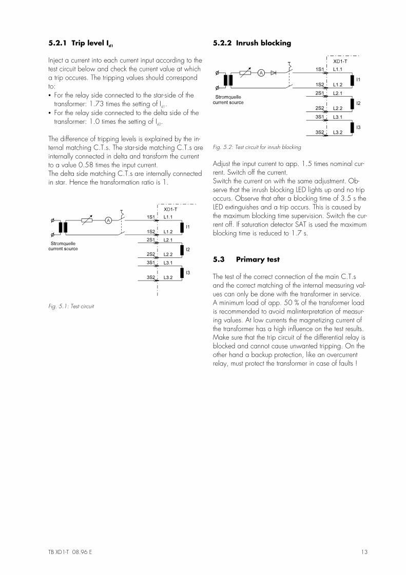
5.2.1 Trip level Id1
Inject a current into each current input according to thetest circuit below and check the current value at whicha trip occures. The tripping values should correspondto:• For the relay side connected to the star-side of the
transformer: 1.73 times the setting of Id1.• For the relay side connected to the delta side of the
transformer: 1.0 times the setting of Id2.
The difference of tripping levels is explained by the in-ternal matching C.T.s. The star-side matching C.T.s areinternally connected in delta and transform the currentto a value 0.58 times the input current.The delta side matching C.T.s are internally connectedin star. Hence the transformation ratio is 1.
Fig. 5.1: Test circuit
5.2.2 Inrush blocking
Fig. 5.2: Test circuit for inrush blocking
Adjust the input current to app. 1.5 times nominal cur-rent. Switch off the current.Switch the current on with the same adjustment. Ob-serve that the inrush blocking LED lights up and no tripoccurs. Observe that after a blocking time of 3.5 s theLED extinguishes and a trip occurs. This is caused bythe maximum blocking time supervision. Switch the cur-rent off. If saturation detector SAT is used the maximumblocking time is reduced to 1.7 s.
5.3 Primary test
The test of the correct connection of the main C.T.sand the correct matching of the internal measuring val-ues can only be done with the transformer in service.A minimum load of app. 50 % of the transformer loadis recommended to avoid malinterpretation of measur-ing values. At low currents the magnetizing current ofthe transformer has a high influence on the test results.Make sure that the trip circuit of the differential relay isblocked and cannot cause unwanted tripping. On theother hand a backup protection, like an overcurrentrelay, must protect the transformer in case of faults !

14 TB XD1-T 08.96 E
5.3.1 Adjustment of the interposing C.T.s
The correct connection and accurate adjustment of theC.T.s can be checked with a voltmeter. For this 7 ter-minals are provided at the lower terminal strip. The as-sociated adjustment potentiometers are arranged abo-ve these terminals. Differences of the main C.T.s up to15 % IN can be adjusted by the potentiometers.
Fig. 5.3: Connection of voltmeter
Information about measuring results can be found onthe following table.
a)Measuring 1 (1L1 - GND)Measuring 2 (2L1 - GND)Measuring 3 (1L1 - 2L1)
550 mV550 mV1100 mV
Correct connection
b)Measuring 1 (1L1 - GND)Measuring 2 (2L1 - GND)Measuring 3 (1L1 - 2L1)
550 mV550 mV0 mV
Current flow of a C.T. (S1 and S2) is mixed-up
c)Measuring 1 (1L1 - GND)Measuring 2 (2L1 - GND)Measuring 3 (1L1 - 2L1)
550 mV550 mV550 mV
Phase position mixed-up (e.g. one current fromphase L1, the other one from phase L2)
d)Measuring 1 (1L1 - GND)Measuring 2 (2L1 - GND)Measuring 3 (1L1 - 2L1)
550 mV550 mV950 mV
Current flow and phase position of a C.T. ismixed-up
Table 5.1: Measuring results
The internal measuring voltages proportional to the in-put currents may be measured as follows. The measur-ing instrument should be a digital multimeter set to AC-voltage measurement, range 2.0 V. The readingsstated below refer to nominal current of the transformer(refering to the order form). Any current value belowmay be calculated proportionally.
Please also note that due to the C.T. errors and thetransformer magnetizing current the measured valuesmight deviate upto 10% from the theoretical values.
Nominal load current of the transformer is generallytransformed to the internal measuring voltage of550 mV AC. Both amplitudes of the measuring volt-ages of one phase, e.g. 1L1 and 1L2, should beequal.The phase angle of the voltages of one phase,e.g. 1L1 and 1L2, must be 180 degrees. A slight de-viation might be caused by the magnetizing current ofthe transformer.
TB XD1-T 08.96 E 15
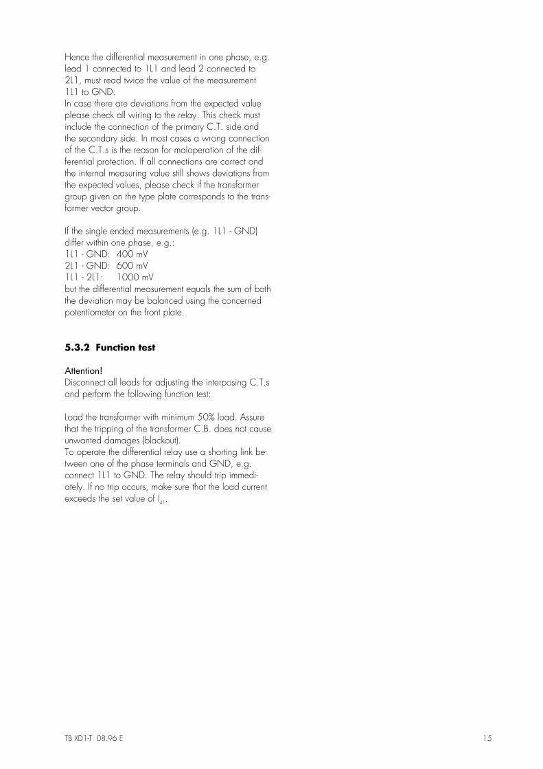
Hence the differential measurement in one phase, e.g.lead 1 connected to 1L1 and lead 2 connected to2L1, must read twice the value of the measurement1L1 to GND.In case there are deviations from the expected valueplease check all wiring to the relay. This check mustinclude the connection of the primary C.T. side andthe secondary side. In most cases a wrong connectionof the C.T.s is the reason for maloperation of the dif-ferential protection. If all connections are correct andthe internal measuring value still shows deviations fromthe expected values, please check if the transformergroup given on the type plate corresponds to the trans-former vector group.
If the single ended measurements (e.g. 1L1 - GND)differ within one phase, e.g.:1L1 - GND: 400 mV2L1 - GND: 600 mV1L1 - 2L1: 1000 mVbut the differential measurement equals the sum of boththe deviation may be balanced using the concernedpotentiometer on the front plate.
5.3.2 Function test
Attention!Disconnect all leads for adjusting the interposing C.T.sand perform the following function test:
Load the transformer with minimum 50% load. Assurethat the tripping of the transformer C.B. does not causeunwanted damages (blackout).To operate the differential relay use a shorting link be-tween one of the phase terminals and GND, e.g.connect 1L1 to GND. The relay should trip immedi-ately. If no trip occurs, make sure that the load currentexceeds the set value of Id1.

16 TB XD1-T 08.96 E
6. Technical data
6.1 Relay case
Relay XD1-T is designed to be fastened onto a DIN-rail acc. to DIN EN 50022, the same as all units of thePROFESSIONAL LINE.
The front plate of the relay is protected with a sealable transparent cover (IP40).
Fig. 6.1: Dimensional drawing
Connection terminals
The connection of up to a maximum 2 x 2.5 mm2 cross-section conductors is possible. For this the transparentcover of the unit has to be removed (see para. 4).

TB XD1-T 08.96 E 17
6.2 Technical Data
Measuring input
Rated data:Rated current IN: 1 A / 5 ARated frequency fN: 50 - 60 Hz
Power consumption in current circuit: at IN = 1 A <0.1 VAat IN = 5 A <0.5 VA
Thermal withstand capabilityin current circuit: dynamic current withstand (half-wave) 250 x IN
for 1 s 100 x INfor 10 s 30 x INcontinuously 4 x IN
Auxiliary voltage
Rated auxiliary voltages UH: 35 - 275 V AC (f = 40 - 70 Hz)19 - 390 V DC
General data
Dropout to pickup ratio: >97%Returning time: <50msReturning time after tripping: 100ms ±10msMinimum operating time: 40ms
Output relays
The output relays have the following characteristics:
Maximum breaking capacity: 250 V AC / 1500 VA / continuous current 6 A
For DC-voltage:
Max. rated making current: 64 A (VDE 0435/0972 and IEC 65/VDE 0860/8.86)Making current: min. 20 A (16 ms)Mechanical life span: 30 x 106 operating cyclesElectrical life span: 2 x 10⁵ operating cycles at 220 V AC / 6 AContact material: silver cadmium oxide (AgCdO)
ohmic L/R = 40 ms L/R = 70 ms300 V DC 0,3 A / 90 W 0,2 A / 63 W 0,18 A / 54 W250 V DC 0,4 A / 100 W 0,3 A / 70 W 0,15 A / 40 W110 V DC 0,5 A / 55 W 0,4 A / 40 W 0,20 A / 22 W60 V DC 0,7 A / 42 W 0,5 A / 30 W 0,30 A / 17 W24 V DC 6,0 A / 144 W 4,2 A / 100 W 2,50 A / 60 W
18 TB XD1-T 08.96 E
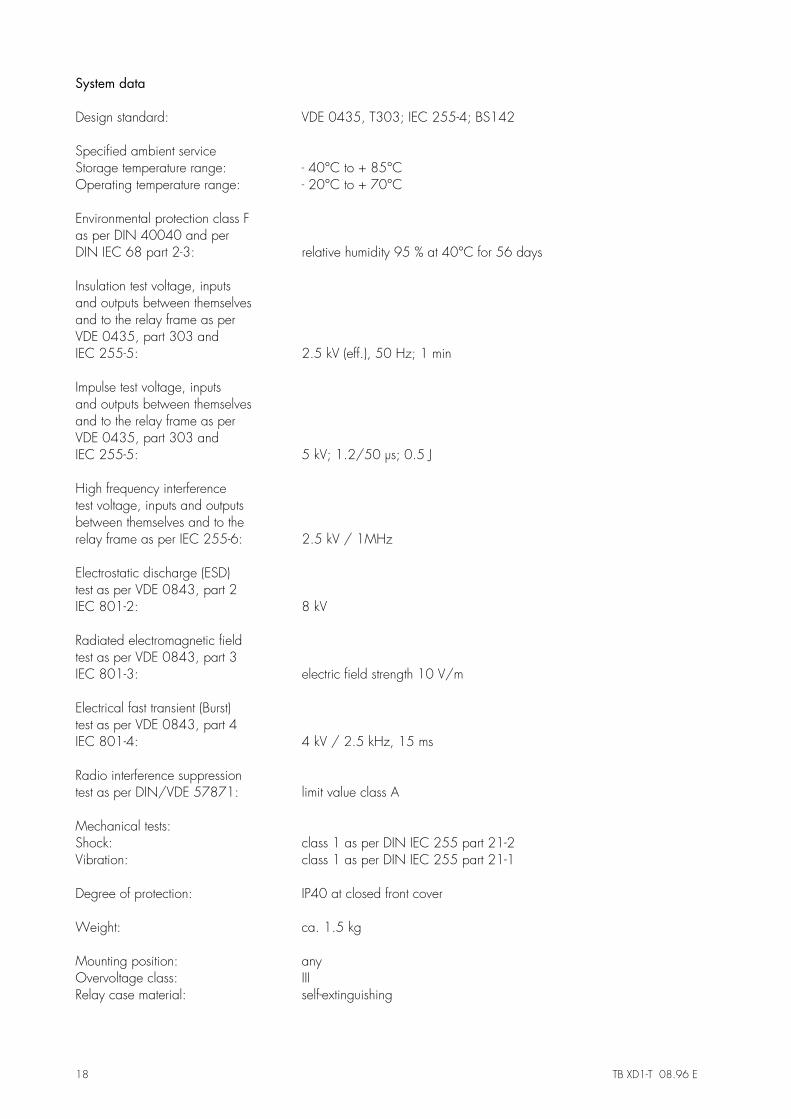
System data
Design standard: VDE 0435, T303; IEC 255-4; BS142
Specified ambient serviceStorage temperature range: - 40°C to + 85°COperating temperature range: - 20°C to + 70°C
Environmental protection class Fas per DIN 40040 and perDIN IEC 68 part 2-3: relative humidity 95 % at 40°C for 56 days
Insulation test voltage, inputsand outputs between themselvesand to the relay frame as perVDE 0435, part 303 andIEC 255-5: 2.5 kV (eff.), 50 Hz; 1 min
Impulse test voltage, inputsand outputs between themselvesand to the relay frame as perVDE 0435, part 303 andIEC 255-5: 5 kV; 1.2/50 µs; 0.5 J
High frequency interferencetest voltage, inputs and outputsbetween themselves and to therelay frame as per IEC 255-6: 2.5 kV / 1MHz
Electrostatic discharge (ESD)test as per VDE 0843, part 2IEC 801-2: 8 kV
Radiated electromagnetic fieldtest as per VDE 0843, part 3IEC 801-3: electric field strength 10 V/m
Electrical fast transient (Burst)test as per VDE 0843, part 4IEC 801-4: 4 kV / 2.5 kHz, 15 ms
Radio interference suppressiontest as per DIN/VDE 57871: limit value class A
Mechanical tests:Shock: class 1 as per DIN IEC 255 part 21-2Vibration: class 1 as per DIN IEC 255 part 21-1
Degree of protection: IP40 at closed front cover
Weight: ca. 1.5 kg
Mounting position: anyOvervoltage class: IIIRelay case material: self-extinguishing

TB XD1-T 08.96 E 19
Tripping characteristics
10-1 100100 101101IS/IN
10-2
10-110-1
100100
Id/IN
10-1 100100 101101IS/IN
10-2
10-110-1
100100
Id/IN
10-1 100100 101101IS/IN
10-2
10-110-1
100100
Id/IN
Setting Id1 = 42,5%
Setting Id2
42,5%
Setting Id1 = 5%
Setting Id1 = 100%Coarse tripping characteristic
Normal tripping characteristic
60%
5%
Fig 6.2: Tripping range
0 1 2 3 4 5 6Id/IN
0
20
40
60
80
100
t [ms]
Fig. 6.3: Tripping time

20 TB XD1-T 08.96 E
Accuracy details
for IS < IN: eI I
Idtrip dset
N
=−
⋅ %100
for IS ≥ IN: eI I
Idtrip dset
S
=−
⋅ %100
where e = relative errorIS = stabilizing currentIN = rated currentIdtrip = measuring differential current which results in trippingIdset = differential current setting
Note: The accuracy details quoted are based on interposing current transfor-mer with exact correction ratio.
Accuracy at reference conditions:• Temperature range -5°C...40°C e ≤ 2,5 %• Frequency range 50 Hz...60 Hz: e ≤ 2,5 %
If the operating temperature or frequency are outside the ranges quote, additional errors are:• Temperature range -20°C...70°C: eadd < 2,5 %• Frequency range 45 Hz...66 Hz: eadd = 1 %

TB XD1-T 08.96 E 21
7. Order form
Transformer differential protection relay XD1-T-Rated current 1 A
5 A15
Latching relay with hand reset SPExtra equipment for reliable-functioning during CT saturation
SAT
Transformer rated capacity MVAVector groupVoltage High voltage side kV ± %
Low voltage sideCurrent transformer ratio High voltage side /
Low voltage side /Rated current High voltage side /
Low voltage side /
Important instruction !In order to ensure the balancing of the transformer differential circuit, the variation of the current refered to the cur-rent transformer secondary shall be in the range from 50 % (0.5 A for 1 A CT and 2.5 A for 5 A CT) up to amaximum of 110 % (1.1 A for 1 A CT and 5.5 A for 5 A CT). We request you to kindly consider this factorwhile choosing the layout of the transformer.
Please check by means of the following formula the correctness of your data: S U I= ⋅ ⋅ 3
Technical data subject to change without notice !

22 TB XD1-T 08.96 E
Setting-list XD1-T
Project: SEG job.-no.:
Function group: = Location: + Relay code: -
Relay functions: Date:
Setting of parameters
Function UnitDefaultsettings
Actualsettings
Id1 Differential current 1 % In 5
Id2 Differential current 2 % In 5