xa9949244 rewiew of the methods used for leak rate
TRANSCRIPT
IAEA-EBP-WWER-10
REWIEW OF THEMETHODS USED FOR
LEAK RATE MEASUREMENTSFOR WWER-440/230
CONFINEMENTSAND WWER-440/213
CONTAINMENTS
XA9949244
A PUBLICATION OF THEEXTRABUDGETARY PROGRAMME ONTHE SAFETY OF WWER AND RBMK
NUCLEAR POWER PLANTS
September 1998
3 0 - 10
M INTERNATIONAL ATOMIC ENERGY AGENCY
The originating Section of this publication in the IAEA was:
Safety Assessment SectionInternational Atomic Energy Agency
Wagramer Strasse 5P.O. Box 100
A-1400 Vienna, Austria
REVIEW OF THE METHODS USED FOR LEAK RATE MEASUREMENTS FOBWWER-440/230 CONFINEMENTS AND WWER-440/213 CONTAINMENTS
IAEA, VIENNA, 1998IAEA-EBP-WWER-10
ISSN 1025-2762
©IAEA, 1998
Printed by the IAEA in AustriaSeptember 1998
FOREWORD
The IAEA initiated in 1990 a programme to assist the countries of central and easternEurope and the former Soviet Union in evaluating the safety of their first generationWWER-440/230 nuclear power plants. The main objectives of the Programme were: toidentify major design and operational safety issues; to establish international consensus onpriorities for safety improvements; and to provide assistance in the review of thecompleteness and adequacy of safety improvement programmes.
The scope of the Programme was extended in 1992 to include RBMK, WWER-440/213 and WWER-1000 plants in operation and under construction. The Programme iscomplemented by national and regional technical co-operation projects.
The Programme is pursued by means of plant specific safety review missions toassess the adequacy of design and operational practices; Assessment of Safety SignificantEvents Team (ASSET) reviews of operational performance; reviews of plant design,including seismic safety studies; and topical meetings on generic safety issues. Othercomponents are: follow-up safety missions to nuclear plants to check the status ofimplementation of IAEA recommendations; assessments of safety improvementsimplemented or proposed; peer reviews of safety studies, and training workshops. TheIAEA is also maintaining a database on the technical safety issues identified for each plantand the status of implementation of safety improvements. An additional important elementis the provision of assistance by the IAEA to strengthen regulatory authorities.
The Programme implementation depends on voluntary extrabudgetary contributionsfrom IAEA Member States and on financial support from the IAEA Regular Budget andthe Technical Co-operation Fund.
For the extrabudgetary part, a Steering Committee provides co-ordination andguidance to the IAEA on technical matters and serves as forum for exchange of informationwith the European Commission and with other international and financial organizations.The general scope and results of the Programme are reviewed at relevant Technical Co-operation and Advisory Group meetings.
The Programme, which takes into account the results of other relevant national,bilateral and multilateral activities, provides a forum to establish international consensus onthe technical basis for upgrading the safety of WWER and RBMK nuclear power plants.
The IAEA further provides technical advice in the co-ordination structure establishedby the Group of 24 OECD countries through the European Commission to providetechnical assistance on nuclear safety matters to the countries of central and eastern Europeand the former Soviet Union.
Results, recommendations and conclusions resulting from the IAEA Programme areintended only to assist national decision makers who have the sole responsibilities for theregulation and safe operation of their nuclear power plants. Moreover, they do not replacea comprehensive safety assessment which needs to be performed in the frame of thenational licensing process.

EDITORIAL NOTE
In preparing this publication for press, staff of the IAEA have made up the pages from theoriginal manuscript(s). The views expressed do not necessarily reflect those of the IAEA, thegovernments of the nominating Member States or the nominating organizations.
Throughout the text names of Member States are retained as they were when the text wascompiled.
The use of particular designations of countries or territories does not imply any judgement bythe publisher, the IAEA, as to the legal status of such countries or territories, of their authorities andinstitutions or of the delimitation of their boundaries.
The mention of names of specific companies or products (whether or not indicated asregistered) does not imply any intention to infringe proprietary rights, nor should it be construed asan endorsement or recommendation on the part of the IAEA.
CONTENTS
SUMMARY 7
1. INTRODUCTION 8
1.1. Background 81.2. Requirements of national nuclear regulatory authorities 121.3. Process of preparation and approval of the test programmes 131.4. Definition of hermetic boundary 211.5. Leakage rate testing as the basis for safety analysis 231.6. Extrapolation of leakage rates obtained at reduced pressure tests to the design
pressure level 231.7. Leak rate definition 24
2. LOCAL LEAK RATE TESTS 26
2.1. Components of the hermetic boundary 262.2. Test methods 27
2.2.1. Local leak test methods for the purpose of leak identification 272.2.2. Method of local leak rate evaluation 29
2.3. Conclusions 30
3. INDIVIDUAL COMPARTMENT TESTS 30
3.1. Compartments tested 303.2. Methods of testing 323.3. Evaluation methods of semi-accessible compartment tests 323.4. Results of individual compartment tests 33
4. INTEGRATED LEAK TEST FOR LEAK IDENTIFICATION 33
4.1. Aims 334.2. Methods of establishing pressure difference 33
4.2.1. Overpressure 344.2.2. Underpressure 34
4.3. Methods of leak identification and leakage rate determination 344.4. Results and experience 35
5. PRE-OPERATIONAL INTEGRATED LEAK RATE TESTS 36
5.1. Aims and procedures of pre-operational ILRT 365.2. Compartments tested and volumes in hermetic compartments 375.3. Systems tested during pre-operational ILRT 375.4. Safety measures under ILRT conditions 375.5. Pre-operational ELRT procedure schedule 38
5.5.1. Pre-operational ILRT preparation 385.5.2. Pressurization of hermetic compartments 385.5.3. Stabilization of parameters in hermetic compartments 395.5.4. Leakage rate measurements and evaluation 395.5.5 Depressurization 39
5.6. Periodical leaktightness tests 395.6.1. Leak rate determination 395.6.2. Pressure measurements 46

5.6.3. Temperature measurements 475.6.4. Air humidity measurements and water vapour partial pressure
determination in hermetic compartments 495.6.5. Measuring and evaluation system 505.6.6. Hermetic boundary examination and leak 51
5.7. Pre-operational ILRT results and experience acquired when implementing thetests 51
6. VERIFICATION INTEGRATED TESTS 53
6.1. Aims 536.2. Methods 536.3. Verification test evaluation 546.4. Experience 54
7. STRUCTURAL INTEGRITY TEST (SIT) 54
7.1. Aims, principles and frequency of SIT 547.2. Inspection methods and measurements 557.3. Structural integrity test procedure 567.4. SIT evaluation 57
8. CONCLUSIONS 57
8.1. Regulatory authorities' approach 578.2. Extrapolation of leakage rate values to the design pressure 578.3. Local leak rate tests 578.4. Leak identification 578.5. Structural integrity 588.6. Integrated leakage rate tests (pre-operational, periodical) 58
REFERENCES 59
ABBREVIATIONS 61
SYMBOLS 62
CONTRIBUTORS TO DRAFTING AND REVIEW 63
SUMMARY
The design and leaktightness characteristics of the confinements in WWER-440/230nuclear power plant (NPP) units and those of the containments in WWER-440/213 unitsoperating in many countries of central and eastern Europe differ significantly from those ofthe containments built in western type pressurized water reactors (PWRs). One of thecharacteristic features of confinements in WWER-440/230 reactors is their comparativelyhigh leakage rate, ranging from several hundred per cent per day upwards. The leak ratesin containments of WWER-440/213 reactors are significantly lower than those of WWER-440/230 units, but in both types of containments the task of leakage rate determinationpresents complex problems which do not appear in western type units.
The methods for leakage rate testing and leakage rate definitions are not the same inall countries operating WWER-440 units. The differences are significant and influencestrongly the leakage rates published for each reactor. The present publication presents indetail the actual methodology being used in different countries and compares it with thewestern practice.
This report spells out the requirements for containment leak rate testing and forintegral tests in the countries operating WWER reactors and compares them with therequirements in force in the USA, Germany and France. It describes the leak rate testingprinciples and leakage rate extrapolation methods, discusses in detail the differences inleakage rate definitions due to significant leakages in WWER containments and explainstheir consequences.
The report addresses the methods of leak rate testing for local leakage and forindividual tests of compartments. It reviews the integrated leak tests and describes in detailand analyses the main leak rate determination methods — the time total method andmomentary leakage rate determination method. Requirements for instrumentation andaccuracy of tests are provided. The procedures for structural integrity tests of WWER-440containments are described and recommendations given.
Finally, Section 8 draws conclusions on all the topics discussed, based on theoperational experience gathered in the countries operating WWER-440 reactors and onjoint expert discussions. The recommendations are aimed at operational staff conductingactual leakage and structural integrity tests of WWER-440 containments, regulatory bodiesevaluating the results of these tests, and national and international organizations active inthe field of WWER safety evaluation.
1. INTRODUCTION
1.1. BACKGROUND
In the system of defence in depth being applied in nuclear power plants, which consistsof the fuel itself, fuel cladding, the reactor coolant system boundary and the containmentenvelope [1] it is the final barrier — i.e. the reactor containment — which is required toprotect the environment in cases of accidents leading to the release of radioactive substancesfrom the primary cooling system. The effectiveness of this barrier prevented any significantradiological consequences in the case of Three Mile Island accident and, contrarely, the lackof containment made it impossible to confine the radioactivity released from the core of theRBMK reactor in the Chernobyl accident.
The requirements concerning the leaktightness and integrity of containment have beenalways very high in western types of nuclear power plants. In the case of eastern reactortechnology, the role of confinement was initially regarded as secondary to the importance ofan easy access to all elements of the plant, which should have assured prevention of leaksfrom the primary system, thus enhancing the role of the third and reducing that of the fourthbarrier in the defense-in-depth approach to Nuclear Plant Safety. As the role of thecontainment became recognized, the design of containment in WWER reactors wasimproved, passing from the confinements of WWER-440/230 units to bubbler condensercontainment of WWER-440/213 reactors.
The design and leaktightness characteristics of the confinements in WWER-440/230nuclear power plant (NPP) units and those of the containments in WWER-440/213 unitsoperating in many countries of central and eastern Europe differ significantly from those ofthe containments built in western type pressurized water reactors (PWRs). One of thecharacteristic features of confinements in WWER-440/230 reactors is their comparativelyhigh leakage rate, ranging from several hundred per cent per day upwards. The leak rates incontainments of WWER-440/213 reactors are significantly lower than those of WWER-440/230 units, but in both types of containments the task of leakage rate determinationpresents complex problems which do not appear in western type units.
The improvements of confinement leaktightness are very important for the upgrading ofthe safety of WWER-440/230 nuclear power plants. For example, in Bohunice V-l, theleaktightness is checked after each reactor maintenance period and the regulatory bodyrequires that the leakages be regularly reduced. This active approach brings results — theleakages in Bohunice V-l have been reduced from initial values being far above 1000% perday to the present day values of less than 100% per day1.
The importance of containment has been always recognized by the IAEA. The SafetyGuide on Safety Functions and Component Classification [2] places the containment in safetyclass 2, as necessary "to limit the release of radioactive material from the reactor containmentduring and after the accident", and adds that this may be achieved by a combination ofcontainment envelope and the use of components that limit the leakage from the containment
'The value of leak rate is defined as the fraction of air contained in the reactor containment which can leak out to thesurrounding atmosphere under maximum pressure difference conditions in a unit time, for example in a second or in aday. In some reports the degree of leaktightness is illustrated by determining the equivalent cross-section area of a leak,or the diameter of a pipe which would involve the same leakage from the containment to the atmosphere. In this reportthe leakage rate will be expressed as the fraction of the air mass which under maximum pressure difference conditionscan leak out per day, and in accordance with the prevailing practice it will be denoted as ' % per day' without repeatingthat '%' means'% of the air mass in the containment'.
envelope or reduce the pressure and temperature inside the containment envelope during andafter accident conditions.
A special safety guide has been published by the IAEA to discuss the design of thecontainment and the tests and inspection of containment and its safety systems [3]. It statesthat "To keep the release of radioactivity to the environment within acceptable limits inaccident conditons a system of confinement shall be provided...such a system can havedifferent engineering solutions, depending on its design requirements". In another paragraphthe guide [3] states that "the design of the containment envelope shall be consistent with theleakage rate adopted to meet the dose limits stipulated by the regulatory body". As therequirements to those dose limits for WWER NPPs have been subject to significant changesover the years, the present day requirements are difficult to satisfy without significant safetyupgradings of the original design.
The guide [3] indicates that the leak rate is affected by factors such as leaktightness,elevation of internal pressure resulting from a postulated initiating event (PIE) and reductionof pressure resulting from the effects of energy management features. These energymanagement features in WWER-440 units are conceptually different for 230 and 213 types,and the approach to evaluation of their effectiveness has been changing over the years. In thecase of WWER-440/230 units the definition of PIE has been also changed, from a smallbreak in the RCS (of 32 mm equivalent diameter) to a medium or large size break of 200 mmequivalent diameter. This influenced the evaluation of the maximum possible pressures in theconfinement, and the requirements to the confinement leaktightness and integral strength.
The guide [3] states that prior to commissioning the containment with its extensions andpenetrations shall be subjected to structural integrity tests at specified overpressures and to aleak rate test programme. According to the world practive, such pre-operational test cover thewhole range of possible pressures, including the calculated peak containment accidentpressure with proper uncertainty margins. In the case of WWER containments however, thepreoperational tests in many units did not go up to the upper pressure limit, following thestatement of [3] that the testing methods and conditions should not themselves produce andunacceptable degradation of safety performance. As the approach to maximum possibleoverpressures could have involved permanent deformations of the containment envelope, thedecision of most plant operators during commissioning was to limit the test pressures tovalues below the maximum accident conditions.
The WWER-440/230 reactors being operated in several countries of central and easternEurope were designed in the 1960s assuming that the design basis accident (DBA) could belimited to a break of a pipe of a diameter of 100 mm, fitted with an orifice of a diameter of32 mm. This assumption was used to determine the parameters of the emergency corecooling system and the confinement structure. For larger breaks, until full rupture of one ofthe two pressurizer surge lines (of 200 mm in diameter each), large pressure release valves inthe confinement boundary were designed to open during the initial pressure peak after theaccident and to release into the environment large amounts of steam escaping from thedisabled reactor coolant system (RCS). It was assumed that the pressure in the confinementwould be much decreased after that, since the bulk of the coolant from the RCS would havebeen released in this first phase of the accident. As the question of leaktightness of theconfinement under such assumptions was not of primary importance, the allowable leakagerates in WWER-440/230 confinements were high.
The shortcomings of the WWER-440/230 confinements were recognized and the newerWWER-440/213 plants were provided with an improved building of much higher strength
and better leaktightness containing a system of water trays and air traps designed to condensesteam and remove some of the air from the reactor compartments after a large loss of coolantaccident (LOCA). In such an event, the system provides fast pressure decrease in thecontainment to sub-atmospheric levels and thus prevents any significant radioactive releasesinto the atmosphere. As the main process is that of steam bubble condensation in water, thesystem is called bubbler condenser containment.
Leak rates in WWER-440/213 containments are significantly lower than in WWER-440/230 confinements, but higher than in western PWR containments. In most plants theleakage rates at the maximum design overpressure range from 5% to 15% per day, but insome plants they are higher, reaching 100%/day or more. Taking into account the rapiddecrease of pressure inside containment after design basis accident (DBA) foreseen in theplant design with bubbler condenser containment, it has been shown that the leakage rates of15% per day at maximum overpressure correspond to an overall integrated leakage after LBLOCA comparable to the overall integrated leakage at full pressure of western PWR plantswith a dry containment. Nevertheless, the question of containment leak rates is important forWWER-440/213 plants and the IAEA has included this issue in the list of safety concernsrequiring further action.
In WWER-440/230 plants the leakage rates are even higher, exceeding as a rule 400%per day at a design maximum overpressure. There is positive experience from the safetyupgrading programme already carried out in the Bohunice NPP, where the initial leakagerates of 5000% and 7000% per day were reduced to values of 400% and 560% per day.Further improvements of confinement leaktightness are planned with the aim of reaching leakrates of 300% per day.
In both types of plants the important factor in reducing leakages is the ability to detectexisting leakages. This involves integral leak rate tests for the whole containment(confinement) at overpressures as high as possible, local leakage tests and appropriatemethods for the interpretation of results. With the improvement of leaktightness the leak ratetesting pressure can be increased, which makes it possible to reveal new locations of leaksand eventually repair them.
The initial shortcomings are difficult to correct. The work in this area is being pursuedand this report presents the actual status of regulatory framework, scientific and technicalbackground for present practices and considerations of resulting situation. Further progress isneeded, one of the issues being the unification of approaches to the definition of leakages incontainments with high leakages rates, so that the data on leaktightness of reactorcontainments could be understood in the same way no matter which country they come from.
The methods for leakage rate testing and leakage rate definitions are not the same in allcountries operating WWER-440 units. The differences are significant and influence stronglythe leakage rates published for each reactor. The present publication, based on a consultantsmeeting organized in the week 8-12 May 1995 within the framework of the ExtrabudgetaryProgramme on the Safety of NPPs with WWER reactors, presents in detail the actualmethodology being used in different countries and compares it with the western practice.
The methods used for containment/confinement leak rate testing in the countriesoperating WWER reactors are partly based on the old Soviet Union regulations, partly onwestern rules such as US ANSI or German KTA regulations, and partly on original workconducted individually by each country. As the containment/confinement leaktightness is of
10
high importance for the safety of the public and significantly influences the level of publicacceptance of WWER plants, the exchange of experience concerning leakage testing methodsshould be encouraged and the best methods made available to all interested parties.
The IAEA has supported the efforts of the countries operating WWER reactors,organizing meetings on containment and confinement performance of WWER-440/213 andWWER-440/230 NPPs [4] and on WWER-440/230 confinement improvement options [5].The problem of methods used for leak rate measurements in containments and confinementsof WWER-440 reactors was found to be important enough to be treated separately.
At the request of the Nuclear Regulatory Authority of the Slovak Republic, the IAEAorganized a meeting on the subject within the framework of the Extrabudgetary Programmeon the Safety of WWER NPPs. The main objectives of the meeting were:
to present the methods of leak rate measurements used in each country operatingWWER NPPs;
to compare the advantages and deficiencies of each method and to make proposals fortheir further improvement.
The questionnaire for the meeting was developed by Slovak specialists on the basis ofthe experience gathered in leak rate testing in the Bohunice NPP. The participants from thecountries operating WWER-440 model 230 and model 213 NPPs prepared technical papersdescribing leak rate testing practices in their plants and providing direct answers to thequestions formulated in the questionnaire.
The first two days of the meeting were dedicated to the presentation of the papers, afterwhich the meeting was divided into working groups which prepared the experts' positions onthe following topics:
requirements of the national regulatory authorities on confinement/containment leak ratetesting methods;local leak rate test methods;integral leak rate test methods;structural integrity testing;methods of evaluating leak rate test results.
The reports prepared by each working group were reviewed in plenary sessions and thefinal conclusions were discussed and agreed upon in the plenary meeting.
This report describes the national requirements for containment leak rate testing and forintegral tests in the countries operating WWER reactors and compares them with therequirements in force in the USA, Germany and France. It describes the essential elements ofleak rate testing and leakage rate extrapolation methods, discusses in detail the differences inleakage rate definitions due to significant leakages in WWER containments and explains theirconsequences.
The report addresses the methods of leak rate testing for local leakage and forindividual tests of compartments. It reviews the integrated leak tests and describes in detailand analyses the main leak rate determination methods — the time total method andmomentary leakage rate determination method. Examples of national requirements for
11
instrumentation and accuracy of tests are provided. The procedures for structural integritytests of WWER-440 containments are described and examples of good practice given.
Section 8 draws conclusions on all the topics discussed, based on the operationalexperience gathered in the countries operating WWER-440 reactors and on joint expertdiscussions. The content of this report is aimed at operational staff conducting actual leakageand structural integrity tests of WWER-440 containments, regulatory bodies evaluating theresults of these tests, and national and international organizations active in the field ofWWER safety evaluation.
1.2. REQUIREMENTS OF NATIONAL NUCLEAR REGULATORY AUTHORITIES
Actual status
The requirements for containment leakage testing in various countries are generallysimilar, aimed at periodical confirmation that leaktightness of the containment lies within theadmissible limits.
In general, the purposes of these inspections and tests can be summarized as follows:
to verify the quality and integrity of hermetic boundary component joints;
to detect leaks applying local leak tests (pressure drop in test volume, medium flowrate) and repair leaks;
to detect leaks on the external and internal hermetic boundary via separatepressurization (underpressure creation in) of individual compartments and integraloverpressure (underpressure) creation within the whole hermetic compartment system,and subsequently to repair leaks;
to evaluate the approximate leak rate of hermetic compartments via controlpressurization before the integrated leakage rate test (ILRT);
to verify the structural integrity of walls and resistance of the liner against maximumdesign pressure, to detect and repair contingent deformations (or destructions);
to evaluate the leakage rate from hermetic compartments in pre-operational (oroperational) conditions and to compare it with the allowable leakage rate value;
to determine pressure (or temperature) in semi-accessible compartments (or air locks) inaccident conditions;
to compare the leakage rate of hermetic compartments evaluated during operationalperiodical ILRT with that evaluated during previous tests.
To meet the above aims, the national nuclear regulatory authorities require that:
(1) Leak tests in compliance with this Programme be conducted and evaluated solely by anorganization authorized for such activities.
(2) The authorized organization prove that sufficient readiness exists in the following fields:
12
methodology (prepared and verified test programmes);material and instrumentation (complete instrumentation for tests);personnel (technicians with certificates for test conduction).
However, specific regulations are different for several areas. In particular, the testpressures required in periodical integral leakage testing are different, e.g. in the USA theyare equal to full accident pressure Pa [6-8], while in the Russian Federation they are equal to0.05 MPa [9], which corresponds to 0.33 Pa. The main national requirements in force invarious countries for preoperational integral tests and leakage rate tests are shown in Table I.Worldwide, the general tendency is to increase test pressures, and not the contrary.
As the standards currently in force in the Russian Federation require the periodical testoverpressure to be 0.05 MPa (Section 8.3.8, [9]), and those in other countries are even morestringent (e.g. in Hungary: 0.07 MPa [10]), it is suggested that this value should not bedecreased.
In Table II the national requirements for periodical integral tests are presented, and inTable III the requirements for local tests.
Local tests in which the measurement of outflow (pressure drop) in test volumes is donewith a pressure gauge, or the inflow into the test volume is measured with a flowmeter, arecalled "type B tests", according to ANSI/ANS 56.8-1987 [8]. The isolation valves andhermetic pressure release valves are not locally leak tested. These valves are only factorytested, and some of them are tested during integral leakage tests for the purpose of leakidentification. Such local tests are called "type C tests" [8].
1.3. PROCESS OF PREPARATION AND APPROVAL OF THE TEST PROGRAMMES
Current status
In the Russian Federation the test programmes are of two types: general and plantspecific. The process of their preparation and approval is shown in Table IV. hi the countriesof central Europe, where the number of NPPs is much less, there are no generalprogrammes, only plant specific programmes. The process of their preparation andacceptance is also shown in Table IV. In particular, in the Slovak Republic, the authorizationfor tests is acquired and certified in compliance with SUBP Ordinance 66/89 of the Code onNational Technical Supervision over the Safety of Technical Equipment in the Field of PowerEngineering (§7 and §15) [16] and with CSKAE (former Czechoslovak Nuclear RegulatoryAuthority) Ordinance 436/90 of the Code on Quality Assurance for Selected Equipment withRegard to Nuclear Safety of Nuclear Facilities (§11) [14].
The authorized organization, in accordance with the above regulations, should provesufficient readiness in the following fields:
methodology (prepared and verified test programmes);material and instrumentation (complete instrumentation for tests);personnel (technicians with certificates for test conduction).
VUEZ (the Power Equipment Research Institute) of Tlmace meets the aforementionedconditions and holds licences valid in both the Slovak and Czech Republics for performingleak and structural integrity tests as well as for evaluating and documenting them.
Text cont. on p. 21.
13

TABLE I. NATIONAL NUCLEAR REGULATORY AUTHORITY REQUIREMENTS FOR INTEGRAL TESTS
TYPES OF TESTSA - integralB - localC - valve test
INTEGRAL TESTS
Document
USA
+ +
+
10 CFR Pt50, App.J [6]ANSI/ANS 56.8/1987 [8]
GERMANY
KTA 3405 2/1979 [11]
FRANCE(for single containment with steel liner)
+ + +
RCC-G/88, Part 3 [12]
RUSSIA
PNAE G-10-021-90[9]
UKRAINE
+ + +
PNAE G-10-021-90[9]
PRE-OPERATIONAL LEAKAGE RATE TESTS
- Test method
- Reduced pressure
- Peak pressure
- Duration of tests
- Acceptance criteria
Absolute
Min. 0.5 Pa
Pa
Min. 8 h, 20 data sets
L <0.75 U
AL/L s0.25
Absolute
0.5 bar
Pa
36 h, can be reduced to 18 h
L + AL <La
AL/L <0.3
Absolute
Intermediary step 0.1 MPa
1.15 Pa
24 h, can be reduced to 16 h
L + AL <0.75 U and Le = 0.74 L,
Lpenet < 0 . 6 L-,
(this gives approximately Lc = 0.74 La)
A.M.
0.5 bar
Pa (1.5 bar)3
A.M., 9 data sets
AL/L <0.5
a = 0.95
L + AL <La4
A.M.
0.5 bar
Pa (1.5 bar)
A.M., 9 data sets
AL/L <0.5
a = 0.95
L 4- AL iLa5
Key: P., - accident (design) pressure; A.M. - any method approved by the regulatory body; N.S. - not specified; La - permissible leak rate; Lpenei - leak rate of penetrations;Lc - maximum acceptable leakage rate under test conditions; Te = 273 -I- 20 = 293 K; Me = 29 g/mole dry air; Ta = 273 + 140 = 413 K; Ma = 21.5 g/mole, LOCA.Footnotes 1 to 5, see Table II.
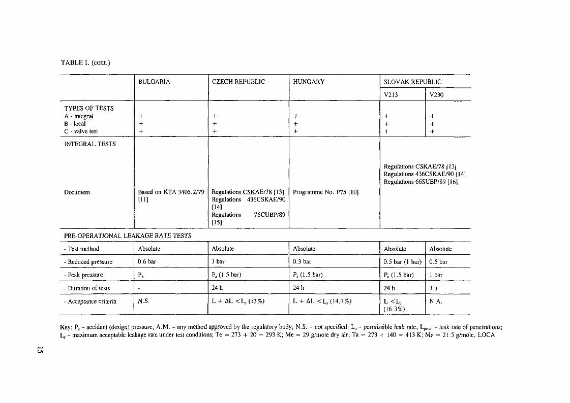
TABLE I. (cont.)
TYPES OF TESTSA - integralB - localC - valve test
INTEGRAL TESTS
Document
BULGARIA
Based on KTA 3405.2/79
[11]
CZECH REPUBLIC
:
Regulations CSKAE/78 [13]Regulations 436CSKAE/90[14]Regulations 76CUBP/89[15]
HUNGARY
:
Programme No. P75 [10]
SLOVAK REPUBLIC
V213
:
V230
I
Regulations CSKAE/78 [13]Regulations 436CSKAE/90 [14]Regulations 66SUBP/89 [16]
PRE-OPERATIONAL LEAKAGE RATE TESTS
- Test method
- Reduced pressure
- Peak pressure
- Duration of tests
- Acceptance criteria
Absolute
0.6 bar
Pa
-
N.S.
Absolute
lbar
P. (1.5 bar)
24 h
L + AL <L,,(13%)
Absolute
0.3 bar
Pa (1.5 bar)
24 h
L + AL <L a (14.7%)
Absolute
0.5 bar( l bar)
P. (1.5 bar)
24 h
L <L a
(16.3%)
Absolute
0.5 bar
1 bar
3h
N.A.
Key: Pa - accident (design) pressure; A.M. - any method approved by the regulatory body; N.S. - not specified; Lkl - permissible leak rate; L ^ , - leak rate of penetrations;Lc - maximum acceptable leakage rate under test conditions; Te = 273 + 20 = 293 K; Me = 29 g/mole dry air; Ta = 273 + 140 = 413 K; Ma = 21.5 g/mole, LOCA.
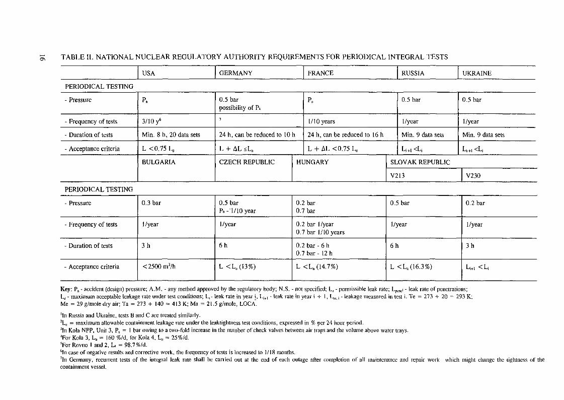
O\ TABLE II. NATIONAL NUCLEAR REGULATORY AUTHORITY REQUIREMENTS FOR PERIODICAL INTEGRAL TESTS
USA GERMANY FRANCE RUSSIA UKRAINE
PERIODICAL TESTING
- Pressure
- Frequency of tests
- Duration of tests
- Acceptance criteria
Pa
3/10 y6
Min. 8 h, 20 data sets
L <0.75 La
BULGARIA
0.5 barpossibility of Pa
7
24 h, can be reduced to 10 h
L + AL <La
CZECH REPUBLIC
Pa
1/10 years
24 h, can be reduced to 16 h
L + AL <0.75 Lc
HUNGARY
0.5 bar
I/year
Min. 9 data sets
Li+I<L|
0.5 bar
I/year
Min. 9 data sets
Lj+i <L;
SLOVAK REPUBLIC
V213 V230
PERIODICAL TESTING
- Pressure
- Frequency of tests
- Duration of tests
- Acceptance criteria
0.3 bar
I/year
3h
<2500m3/h
0.5 barPa-1/10 year
I/year
6h
L <La(13%)
0.2 bar0.7 bar
0.2 bar I/year0.7 bar 1/10 years
0.2 bar - 6 h0.7 bar - 12 h
L <La(14.7%)
0.5 bar
I/year
6 h
L <La(16.3%)
0.2 bar
I/year
3h
Li+t < L;
Key: Pa - accident (design) pressure; A.M. - any method approved by the regulatory body; N.S. - not specified; L., - permissible leak rate; L .̂̂ i - leak rate of penetrations;Lo - maximum acceptable leakage rate under test conditions; L r leak rate in year i, Li+| - leak rate in year i + 1, L,,u - leakage measured in test i. Te = 273 + 20 = 293 K;Me = 29 g/mole dry air; Ta = 273 + 140 = 413 K; Ma = 21.5 g/mole, LOCA.
'In Russia and Ukraine, tests B and C are treated similarly.2Le = maximum allowable containment leakage rate under the leaktightness test conditions, expressed in % per 24 hour period.3In Kola NPP, Unit 3, Pa = 1 bar owing to a two-fold increase in the number of check valves between air traps and the volume above water trays."For Kola 3, La = 160 %/d, for Kola 4, L, = 25%/d.5For Rovno 1 and 2, L, = 98.7%/d.6In case of negative results and corrective work, the frequency of tests is increased to 1/18 months.7In Germany, recurrent tests of the integral leak rate shall be carried out at the end of each outage after completion of all maintenance and repair work which might change the tightness of thecontainment vessel.
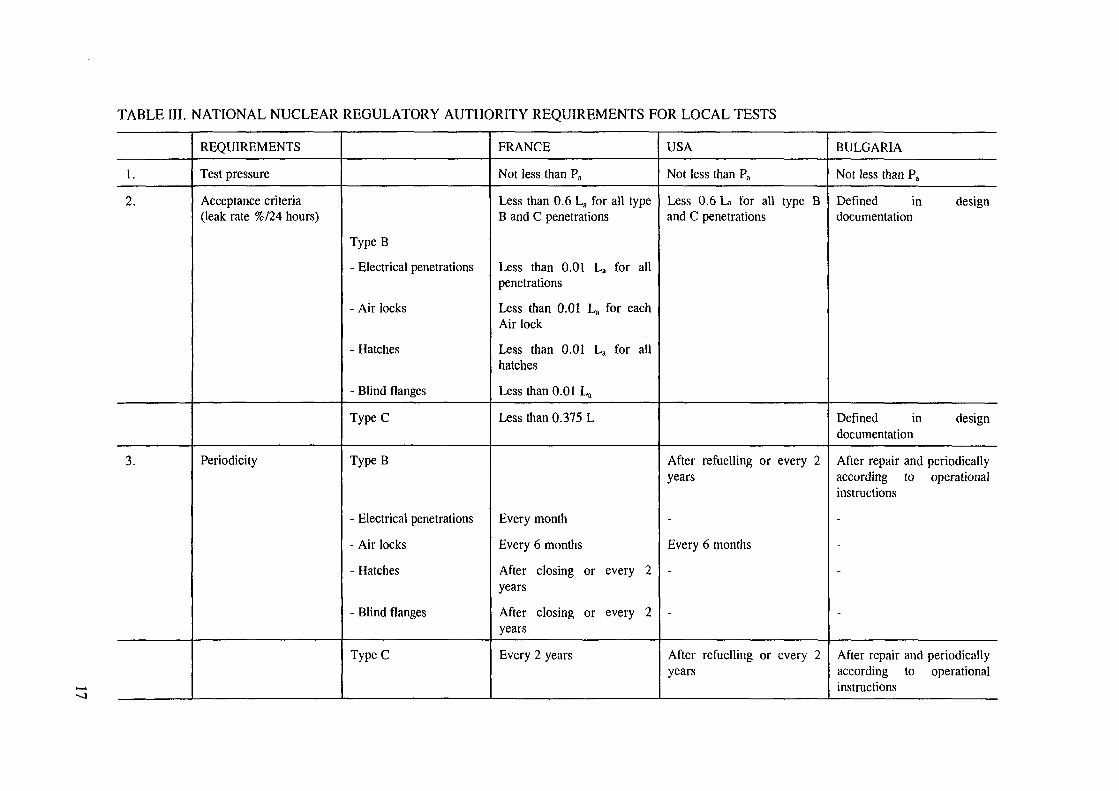
TABLE III. NATIONAL NUCLEAR REGULATORY AUTHORITY REQUIREMENTS FOR LOCAL TESTS
1.
2.
3.
REQUIREMENTS
Test pressure
Acceptance criteria(leak rate %/24 hours)
Periodicity
TypeB
- Electrical penetrations
- Air locks
- Hatches
- Blind flanges
TypeC
TypeB
- Electrical penetrations
- Air locks
- Hatches
- Blind flanges
TypeC
FRANCE
Not less than Pa
Less than 0.6 La for all typeB and C penetrations
Less than 0.01 La for allpenetrations
Less than 0.01 La for eachAir lock
Less than 0.01 La for allhatches
Less than 0.01 La
Less than 0.375 L
Every month
Every 6 months
After closing or every 2years
After closing or every 2years
Every 2 years
USA
Not less than Pa
Less 0.6 La for all type Band C penetrations
After refuelling or every 2years
-
Every 6 months
-
-
After refuelling or every 2years
BULGARIA
Not less than Pa
Defined in designdocumentation
Defined in designdocumentation
After repair and periodicallyaccording to operationalinstructions
-
-
-
-
After repair and periodicallyaccording to operationalinstructions
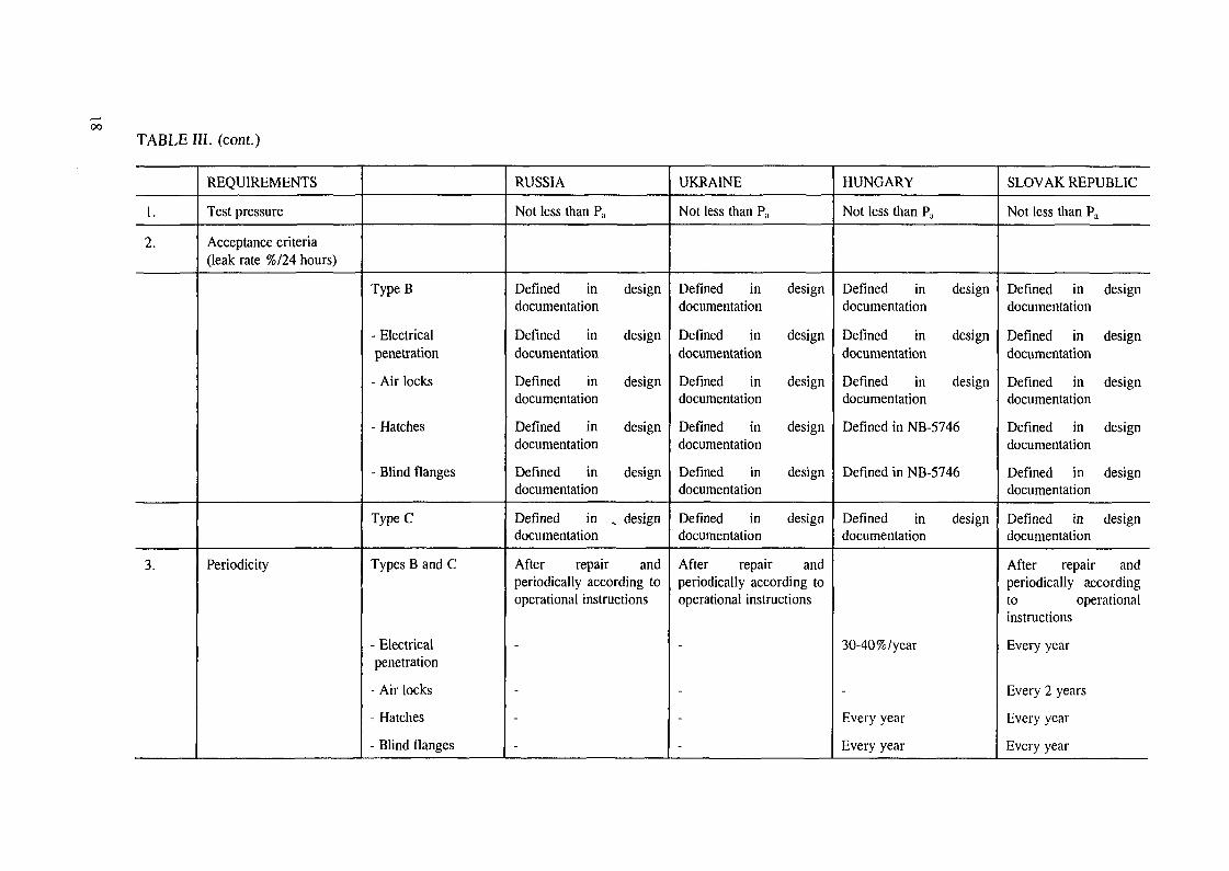
TABLE III. (cont.)
1.
2.
3.
REQUIREMENTS
Test pressure
Acceptance criteria(leak rate %/24 hours)
Periodicity
TypeB
- Electricalpenetration
- Air locks
- Hatches
- Blind flanges
TypeC
Types B and C
- Electricalpenetration
- Air locks
- Hatches
- Blind flanges
RUSSIA
Not less than Pa
Defined indocumentation
Defined indocumentation
Defined indocumentation
Defined indocumentation
Defined indocumentation
Defined indocumentation
design
design
design
design
design
, design
After repair andperiodically according tooperational instructions
-
-
-
-
UKRAINE
Not less than Pa
Defined indocumentation
Defined indocumentation
Defined indocumentation
Defined indocumentation
Defined indocumentation
Defined indocumentation
design
design
design
design
design
design
After repair andperiodically according tooperational instructions
-
-
-
-
HUNGARY
Not less than Pa
Defined indocumentation
Defined indocumentation
Defined indocumentation
design
design
design
Defined in NB-5746
Defined in NB-5746
Defined indocumentation
30-40%/year
-
Every year
Every year
design
SLOVAK REPUBLIC
Not less than Pa
Defined in designdocumentation
Defined in designdocumentation
Defined in designdocumentation
Defined in designdocumentation
Defined in designdocumentation
Defined in designdocumentation
After repair andperiodically accordingto operationalinstructions
Every year
Every 2 years
Every year
Every year
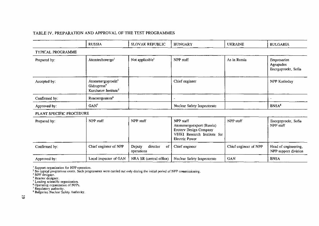
TABLE IV. PREPARATION AND APPROVAL OF THE TEST PROGRAMMES
RUSSIA SLOVAK REPUBLIC HUNGARY UKRAINE BULGARIA
TYPICAL PROGRAMME
Prepared by:
Accepted by:
Confirmed by:
Approved by:
Atomtechenergo1
Atomenergoproekt3
Gidropress4
Kurchatov Institute5
Rosenergoatom6
GAN7
Not applicable2 NPP staff
Chief engineer
-
Nuclear Safety Inspectorate
As in Russia EmpresariosAgrupadosEnergoproekt, Sofia
NPP Kozloduy
-
BNSA8
PLANT SPECIFIC PROCEDURE
Prepared by:
Confirmed by:
Approved by:
NPP staff
Chief engineer of NPP
Local inspector of GAN
NPP staff
Deputy director ofoperations
NRA SR (central office)
NPP staffAtomenergoexport (Russia)Eroterv Design CompanyVEIKI Research Institute forElectric Power
Chief engineer
Nuclear Safety Inspectorate
NPP staff
Chief engineer of NPP
GAN
Energoproekt, SofiaNPP staff
Head of engineering,NPP support division
BNSA
1 Support organization for NPP operation.2 No typical programme exists. Such programmes were carried out only during the initial period of NPP commissioning.3 NPP designer.4 Reactor designer.5 Leading scientific organization.6 Operating organization of NPPs.7 Regulatory authority.8 Bulgarian Nuclear Safety Authority.

TABLE IV. (cont.)
TEST
Performed by:
Confirmed by:
Approved by:
NPP staff
Chief engineer of NPP
Local inspector of GAN
NPP staff
Head of the technicaldept.Deputy director ofoperations
NRA SR (centraloffice)9
NPP staff
Plant shift supervisor
Nuclear Safety Inspectorate
NPP staff
Chief engineer of NPP
GAN
NPP staff
Head of engineering,NPP support division
BNSA
DECISIONS
Development of technicaldecisions concerningcontainment acceptance:
Accepted by:
Confirmed by:
Approved by:
Atomtechenergo &Rosenergoatom
AtomenergoproektVNIIAES"GidropressKurchatov Institute
Rosenergoatom
GAN
According to testresults10
According to testresults
-
BNSA
9 Minor changes of equipment can be accepted by the local inspector. The local inspector performs field inspections during the test.10 Fulfillment of acceptance criteria is stated in the test results. If they are fulfilled, further operation is allowed without additional documents. If they are not, operation is not allowed, correctionsmust be made and the test repeated.11 Scientific institute for NPPs.
1.4. DEFINITION OF HERMETIC BOUNDARY
The hermetic boundary for the WWER-440/213 units is determined in the design and isthe same for all units.
The main hermetic zone of the WWER-440/213 NPPs is designed for an overpressureof 150 kPa and consists of three main components:
steam generator (SG) compartment;bubble condenser tower;vent centre.
These three parts are mutually interconnected and separated from the environment by meansof reinforced concrete walls lined with an hermetic liner.
Furthermore, the hermetic zone also comprises associated hermetic compartmentswhich are situated on the outer or inner sides of the main hermetic compartments. Thesehermetic 'sub-compartments' are partially isolated from the main hermetic compartmentsduring operation. They consist of:
seven semi-accessible compartments;four air locks;four bubble condenser air traps;the reactor platform.
A representative list of compartments is provided in Table V, based on the informationgiven in [17].
Hermetic compartments of the WWER-440/230 NPPs are even simpler than those ofthe WWER-440/213 models and are designed for an overpressure of 100 kPa.
The hermetic zone of the WWER-440/230 consists of two main parts:
the SG compartment;the recirculation vent system.
These are complemented by associated hermetic compartments consisting of:
two semi-accessible compartments;one air lock;the reactor compartment.
We can distinguish:
an external hermetic boundary, separating the main and associated hermeticcompartments from the outside atmosphere; andan internal hermetic boundary, separating the main hermetic compartments from thoseassociated with them.
The equipment and components which form the external hermetic boundary are subjectto leakage rate tests. Those forming the internal boundary are subject to less stringentrequirements.
Individual hermetic boundary components are verified applying local leak test methodsand the hermetic boundary as a whole is tested using integrated leak test methods.
21

TABLE V. COMPARTMENTS INCLUDED IN THE CONTAINMENTS OF WWER-440/213 UNITS
The leaktight volume is a rectangular compartment of a cross-section of 54 x 75 m, limitedat the bottom by the lowest floor at a level of-6.5 m and at the top by the ceiling at a levelof 46.44 m
1.
2.
3.
4.
5.
6.
7.
8.
9.
10.
11.
12.
13.
13a.
14.
15.
16.
17.
18.
19.
ELEVATION (in mm)
FLOOR
6000
10 500
6000
12 100
6000
6000
12 100
10 500
10 500
10 500
10 500
10 500
10 500
600
0
-6500
-6100
11600
6000-2800
60006000
CEILING
17 000
17 400
11500
17 400
13 000
11500
17 400
17 400
17 400
25 500
25 500
13 500
13 500
9800
5000
5000
11600
22 400
9800
46 40046 400
COMPARTMENTS
Compartment of SGs.
Drive compartments associated with SGcompartments.
Venting room of SG compartment.
As above.
Corridor for release of gas-steam mixturefrom the compartments of pumps and SGsinto the tower of the bubbler condenser (up tobut not including the water trays).
Compartments of drives for the ventingsystem of the SG compartment.
As above.
Compartments of heat exchangers of RCSblowdowns.
Compartments of filters of SWO-1.
Hydroaccumulator compartments.
Compartment of the pressurizer and itsbubbler condenser.
Venting room of the pressurizer.
Compartment of drives for the venting systemof the pressurizer.
Compartments of the I&C for SGs and RCPs.
Air locks on all levels, except forcompartments of RCPs and SGs.
Compartments of the recirculation system.
Reactor shaft.
The volume under the reactor cap.
Other air locks of the containment.**
Bubbler condenser tower:(a) air volume above the water trays(b) volume of air traps
VOLUME (m 3)
9100*
1800
210
220
4725
130
135
240
86
900
900
85
85
653
70
4x500
275
160
210
645016 780
* The volume of RCPs and SGs is given taking into account the air locks, cable penetrations and corridorsadjoining them.
••Coefficient of filling up the volume with equipment K = 0.2.
22
With regard to WWER-440/230 units, the differences among the various NPPs aresignificant and no common definition of confinement boundary can be given. An example ofthe situation in the Kozloduy NPP is described in [18].
1.5. LEAKAGE RATE TESTING AS THE BASIS FOR SAFETY ANALYSIS
The leakage rate test conditions are different from those existing during accidentconditions.
The temperatures during accidents are higher and the fraction of steam in the air issignificant. This has given rise to doubts over which leakage values — those obtained in theexperiment or some other values recalculated for accident conditions — should be used in asafety analysis.
The consultants confirmed that in all countries which operate WWER NPPs, the valuesfound in the experiments are assumed to be valid for accident conditions. This approach isconservative, as illustrated by the formula given in the French regulations which expresslyaddress this issue.
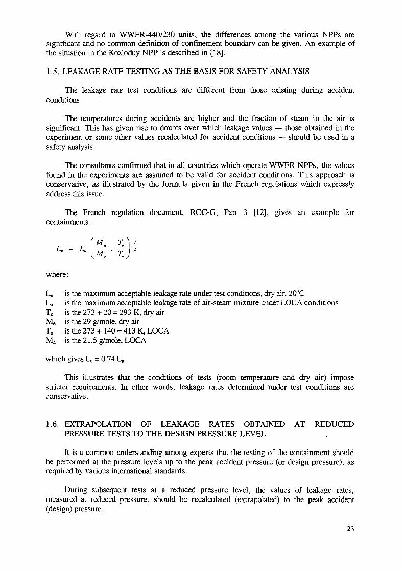
The French regulation document, RCC-G, Part 3 [12], gives an example forcontainments:
where:
Le is the maximum acceptable leakage rate under test conditions, dry air, 20°CLa is the maximum acceptable leakage rate of air-steam mixture under LOCA conditionsTe is the 273 + 20 = 293 K, dry airMe is the 29 g/mole, dry airTa is the 273 + 140 = 413 K, LOCAMa is the 21.5 g/mole, LOCA
which gives Le = 0.74 La.
This illustrates that the conditions of tests (room temperature and dry air) imposestricter requirements. In other words, leakage rates determined under test conditions areconservative.
1.6. EXTRAPOLATION OF LEAKAGE RATES OBTAINED AT REDUCEDPRESSURE TESTS TO THE DESIGN PRESSURE LEVEL
It is a common understanding among experts that the testing of the containment shouldbe performed at the pressure levels up to the peak accident pressure (or design pressure), asrequired by various international standards.
During subsequent tests at a reduced pressure level, the values of leakage rates,measured at reduced pressure, should be recalculated (extrapolated) to the peak accident(design) pressure.
23
However, it is known that a number of WWER-440 units have not been tested at designpressure levels due to various reasons, hi the case of such units, the leakage rates measured atreduced pressure levels should be extrapolated to the full design pressure using the results ofthe previous tests under maximum achieved level of overpressure.
The consultants believe that there is no universal theoretical relationship for theextrapolation of the results, since each unit has its own individual hydraulic characteristics ofleakages. Therefore, in extrapolating the values of leakage rates measured at test pressures,the data experimentally obtained for the given unit should be used.
1.7. LEAK RATE DEFINITION
The experts are of the opinion that the definitions of leakage rate stated in variouswestern standards which use similar wording are in general applicable to the WWER-440NPPs.
However, in view of the significant leakage rates of WWER-440 bubbler condensercontainments and WWER-440/230 confinements, it is not possible to consider the testpressure to be constant during the 24 hour test. Therefore, the notion of leakage rate "at peakaccident pressure Pa" given for instance in the American standards can be interpreted either:
(1) as the leakage determined during the test in which the initial pressure was Pa, and thenthe pressure was dropping due to the containment leakage; or
(2) as the momentary leakage rate in the time interval when the average pressure was equalto Pa.
In practice both approaches are used in the countries operating WWER-440 NPPs. Thefirst approach is applied in Czech and Slovak Republics and in Hungary [19-23,10], whilethe second is used in Bulgaria [18], in the Russian Federation [24] and in Ukraine [17]. Theleakage rates quoted in the official documents are related to these two different approaches. Inorder to avoid misunderstandings, the experts recommend that the definition of the leak rate(for initial test pressure or for average test pressure) be given for each test result.
The leak rate is usually defined as the loss of air in the containment during a 24 hourtest, measured in per cent (%/day). hi reality the tests can be conducted for shorter timeperiods, especially when periodical testing is carried out. Then the leak rate is determinedwithin a shorter time span and recalculated for the 24 hour test interval. The method ofrecalculation is especially important for tests in which the initial test pressure is taken as thepeak accident condition.
For small leakage rate values such as those observed in full pressure PWRcontainments, the decrease of containment pressure during testing will have little influence onthe containment leak rate. For WWER-440/213 containments with leakage rates of 1-20%/day, 24 hour tests can still reasonably be conducted and the results can be correlated tothe initial test pressure. With respect to WWER-440 confinements with higher leakage rates,e.g. reaching 100%/day or more, the approach of relating the measured leakage rate to theaverage pressure in the test interval is applied in Bulgaria, Russia and Ukraine. This is inconformity with Russian regulations which require that the measured leakage rate be assignedto the average test pressure within the measurement interval.
24
According to the information presented by Russian experts, the measurements areperformed in such a way that the experiment starts with a pressure slightly higher thanthe calculated peak accident pressure. The leak rate is measured during the time intervalwhen the pressure falls to a value slightly below the peak accident pressure. The averagepressure value is determined during this interval, and the leakage values are used todetermine the equivalent diameter of the opening in the containment. This procedure canbe repeated for several points as the pressure drops. The value of the equivalent diameterof the opening is calculated for each of the average pressure values in each time interval.Therefore, the value of the leakage rate finally given for the plant, if it is measured in%/day, is the value measured for the time interval in which the average pressure valuewas the same as the peak accident pressure value.
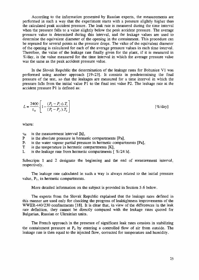
In the Slovak Republic the determination of the leakage rates for Bohunice VI wasperformed using another approach [19-23]. It consists in predetermining the finalpressure of the test, so that the leakages are measured for a time interval in which thepressure falls from the initial value PI to the final test value P2. The leakage rate at theaccident pressure PI is defined as:
L =2400
*«I - " [%/day]
where :
xH is the measurement interval [h] ,P is the absolute pressure in hermet ic compar tments [Pa] ,Pr is the water vapour part ial p ressu re in hermet ic compar tments [Pa] ,T is the temperature in hermetic compartments [K],L is the leakage rate from hermetic compartments [ %/24 h].
Subscripts 1 and 2 designate the beginning and the end of measurement interval,respectively.
The leakage rate calculated in such a way is always related to the initial pressurevalue, Pi, in hermetic compartments.
More detailed information on the subject is provided in Section 5.6 below.
The experts from the Slovak Republic explained that the leakage rates defined inthis manner are used only for checking the progress of leaktightness improvements of theWWER-440/230 confinements [18]. It is clear that, in view of the differences in the leakrate definition, they cannot be directly compared with the leakage rates quoted forBulgarian, Russian or Ukrainian units.
The French approach in the presence of significant leak rates consists in stabilizingthe containment pressure at Pa by entering a controlled flow of air from outside. Theleakage rate is then equal to the injected flow, corrected for temperature and humidity.
25
2. LOCAL LEAK RATE TESTS
Local leak rate tests are effective steps for the improvement of the leaktightness ofconfinement.
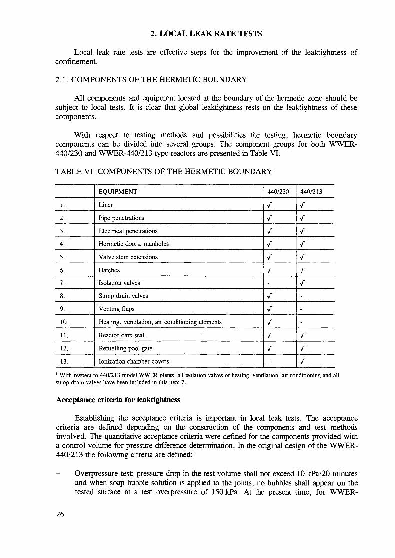
2.1. COMPONENTS OF THE HERMETIC BOUNDARY
All components and equipment located at the boundary of the hermetic zone should besubject to local tests. It is clear that global leaktightness rests on the leaktightness of thesecomponents.
With respect to testing methods and possibilities for testing, hermetic boundarycomponents can be divided into several groups. The component groups for both WWER-440/230 and WWER-440/213 type reactors are presented in Table VI.
TABLE VI. COMPONENTS OF THE HERMETIC BOUNDARY
1.
2.
3.
4.
5.
6.
7.
8.
9.
10.
11.
12.
13.
EQUIPMENT
Liner
Pipe penetrations
Electrical penetrations
Hermetic doors, manholes
Valve stem extensions
Hatches
Isolation valves1
Sump drain valves
Venting flaps
Heating, ventilation, air conditioning elements
Reactor dam seal
Refuelling pool gate
Ionization chamber covers
440/230
/
/
/
V"
/
-
/
/
/
-
440/213
/
/
V
/
/
/
V"
-
-
-
/
/1 With respect to 440/213 model WWER plants, all isolation valves of heating, ventilation, air conditioning and allsump drain valves have been included in this item 7.
Acceptance criteria for leaktightness
Establishing the acceptance criteria is important in local leak tests. The acceptancecriteria are defined depending on the construction of the components and test methodsinvolved. The quantitative acceptance criteria were defined for the components provided witha control volume for pressure difference determination. In the original design of the WWER-440/213 the following criteria are defined:
Overpressure test: pressure drop in the test volume shall not exceed 10 kPa/20 minutesand when soap bubble solution is applied to the joints, no bubbles shall appear on thetested surface at a test overpressure of 150 kPa. At the present time, for WWER-
26
440/213 units no pressure decrease should be detected for electrical and pipepenetration (new criteria).
Quantitative overpressure test: flow rate (equal to the flow rate through the leak) shallnot exceed 0.03 mVh per 1 m of sealing (i.e., 30 L/h at a test overpressure of150 kPa.).
Underpressure test: no bubbles shall appear on the tested surface.
Ultrasonic or acoustic tests: no air leakage shall be audible through the tested joints.
Adhesive dye test: the imprint shall be clearly visible on at least on 60% of the sealingwidth.
The acceptance criteria for WWER-440/230 units are not fully defined in the originaldocumentation. According to the consultants, the criteria for WWER-440/213 plants shouldequally be applied for WWER-440/230 plants.
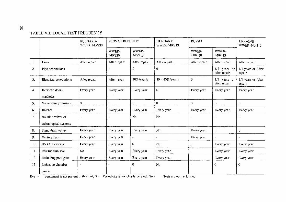
Test frequency
The local test frequency for WWER-440/230 and WWER-440/213 plants is usuallydefined in the operational procedures.
The local test frequency practiced at different units is illustrated in Table VII.
2.2. TEST METHODS
With regard to the design of individual technological nodes, different methods of leaktesting are applied to hermetic boundary components for the purpose of leak identificationand local leak rate evaluation.
2.2.1. Local leak test methods for the purpose of leak identification
Sensory check
Applying the visual method, cracks from the width of 0.1 mm can be identified withgood lighting (500 Lx). The acoustic method can be used to identify major leaks. Thismethod is very effective but difficult to use as it causes loud and disturbing background noise.The tactile method also requires a pressure difference and direct access to the examined jointas well.
Soap bubble method
The most frequent and effective method of leak identification. Leakages of about1.10"2 (l/s)/Pa can be detected. The soap solution used for detection shall have the propercharacteristics.
Underpressure (vacuum) method
This method is used to test the liner field welds on flat compartment wall, floor orceiling surfaces, welds of door frames and equipment hatches, i.e. all welds not equippedwith their own test volumes. Leakages of about 1.10'3 (l/s)/Pa can be detected.
27
N00
TABLE VII. LOCAL TEST
l.
2.
3.
4.
5.
6.
7.
8.
9.
10.
11.
12.
13.
Liner
Pipe penetrations
Electrical penetrations
Hermetic doors,
manholes
Valve stem extensions
Hatches
Isolation valves of
technological systems
Sump drain valves
Venting flaps
HVAC elements
Reactor dam seal
Refuelling pool gate
Ionization chamber
covers
FREQUENCY
BULGARIAWWER-440/230
After repair
-
After repair
Every year
0
Every year
-
Every year
Every year
Every year
No
Every year
-
SLOVAK REPUBLIC
WWER-440/230
After repair
0
After repair
Every year
0
Every year
-
Every year
Every year
Every year
Every year
Every year
-
WWER-440/213
After repair
0
30%/yearly
Every year
0
Every year
No
Every year
-
0
Every year
Every year
0
HUNGARYWWER-440/213
After repair
0
30 - 40% /yearly
0
0
Every year
No
No
-
No
Every year
Every year
No
RUSSIA
WWER-440/230
After repair
-
0
Every year
0
Every year
-
Every year
Every year
0
-
-
-
WWER-440/213
After repair
1/4 years orafter repair
1/4 years orafter repair
Every year
0
Every year
0
0
-
Every year
Every year
Every year
0
UKRAINEWWER-440/213
After repair
1/4 years or Afterrepair
1/4 years or Afterrepair
Every year
0
Every year
0
0
-
Every year
Every year
Every year
0
Key: - Equipment is not present in this unit; 0 - Periodicity is not clearly defined; No - Tests are not performed.
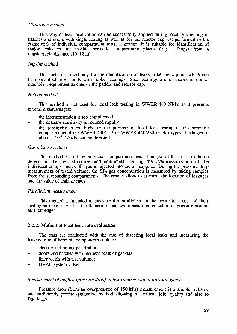
Ultrasonic method
This way of leak localization can be successfully applied during local leak testing ofhatches and doors with single sealing as well as for the reactor cap test performed in theframework of individual compartment tests. Likewise, it is suitable for identification ofmajor leaks in unaccessible hermetic compartment places (e.g. ceilings) from aconsiderable distance (10-12 m).
Imprint method
This method is used only for the identification of leaks in hermetic joints which canbe dismantled, e.g. joints with rubber sealings. Such sealings are on hermetic doors,manholes, equipment hatches or the paddle and reactor cap.
Helium method
This method is not used for local leak testing in WWER-440 NPPs as it presentsseveral disadvantages:
the instrumentation is too complicated;the detector sensitivity is reduced rapidly;the sensitivity is too high for the purpose of local leak testing of the hermeticcompartments of the WWER-440/213 or WWER-440/230 reactor types. Leakages ofabout 1.10"5 (l/s)/Pa can be detected.
Gas mixture method
This method is used for individual compartment tests. The goal of the test is to definedefects in the civil structures and equipment. During the overpressurization of theindividual compartments SF6 gas is injected into the air supplied. During the pressure dropmeasurement of tested volume, the SFs gas concentration is measured by taking samplesfrom the surrounding compartments. The results allow to estimate the location of leakagesand the value of leakage rates.
Parallelism measurement
This method is intended to measure the parallelism of the hermetic doors and theirsealing surfaces as well as the flatness of hatches to assure equalization of pressure aroundall their edges.
2.2.2. Method of local leak rate evaluation
The tests are conducted with the aim of detecting local leaks and measuring theleakage rate of hermetic components such as:
electric and piping penetrations;doors and hatches with resilient seals or gaskets;liner welds with test volume;HVAC system valves.
Measurement of outflow (pressure drop) in test volumes with a pressure gauge
Pressure drop (from an overpressure of 150 kPa) measurement is a simple, reliableand sufficiently precise qualitative method allowing to evaluate joint quality and also tofind leaks.
29
Measurement of inflow into the test volume with aflowmeter
Measurement of inflow into the test volume is a quantitative method of local testingwhich, in addition to leak localization, can also determine leakage rate of the pressurizationmedium per unit of time.
Supplied pressurization air compensates for the air lost through leaks, i.e. the measuredflow rate corresponds to the leakage rate.
A summary of the local test methods applied at different WWER-440 units is providedin Table VIII.
2.3. CONCLUSIONS
(1) Local leak rate tests are effective steps towards improving the WWER-440 confinementleaktightness.
(2) Local leak rate tests have to be performed periodically at all units according to nationalrequirements and international practice.
(3) Tests and inspections are performed after any job which could affect the confinementleaktightness.
(4) For improvement of local test quality, unsuitable penetration elements should bemodernized.
3. INDIVIDUAL COMPARTMENT TESTS
The individual compartment tests performed at the Paks NPP are pre-operational. InRussian and Slovak NPP units, individual compartment tests are performed periodically.
3.1. COMPARTMENTS TESTED
Associate hermetic compartments (sub-compartments), which are separated from themain hermetic compartments by an internal hermetic boundary, can be divided into:
semi-accessible compartments and air locks;bubble condenser air traps in the case of WWER-440/213 plants.
Acceptance criteria exist currently only for Slovak NPPs and are plant specific asfollows:
semi-accessible compartments — extrapolated pressure increase:
Skoda type doors: dP/dt = 10 kPa after the first minuteBLR type doors: dP/dt = 10 kPa after the second minute
Air lock - extrapolated pressure increase:
dP/dt = 3 kPa after 1 hour
30
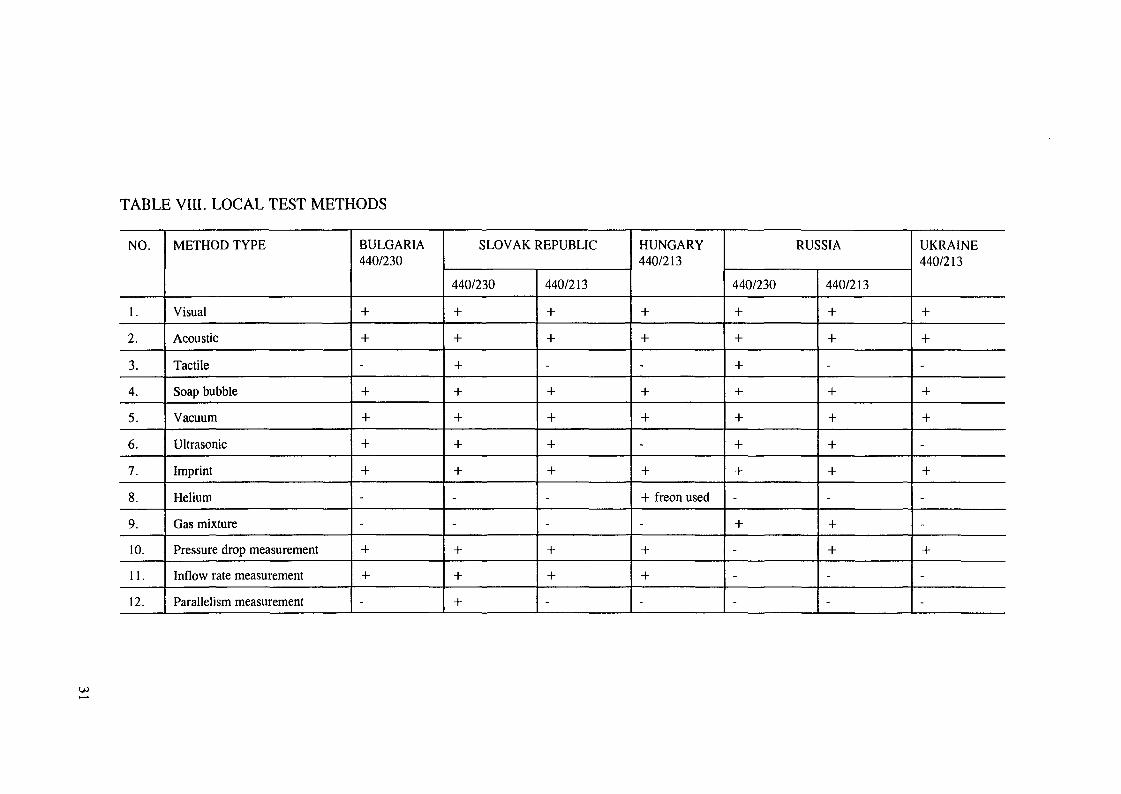
TABLE VIII. LOCAL TEST METHODS
NO.
1.
2.
3.
4.
5.
6.
7.
8.
9.
10.
11.
12.
METHOD TYPE
Visual
Acoustic
Tactile
Soap bubble
Vacuum
Ultrasonic
Imprint
Helium
Gas mixture
Pressure drop measurement
Inflow rate measurement
Parallelism measurement
BULGARIA440/230
+
+
-
+
+
+
+
-
-
+
+
-
SLOVAK REPUBLIC
440/230
+
+
+
+
+
+
+
-
-
+
+
+
440/213
+
+
-
+
+
+
+
-
-
+
+
-
HUNGARY440/213
+
+
-
+
+
-
+
+ freon used
-
+
+
-
RUSSIA
440/230
+
+
+
+
+
+
+
-
+
-
-
-
440/213
+
+
-
+
+
+
+
-
+
+
-
-
UKRAINE440/213
+
+
-
+
+
-
+
-
-
+
-
-
3.2. METHODS OF TESTING
Three basic test methods are used for individual compartment tests:
(1) Individual compartments tests with overpressure:
- overpressure created in the compartments tested, and
- overpressure created around the compartment tested.
(2) Individual compartment tests with underpressure.
(3) Individual tests of compartments with the gas mixture injection method.
The purpose of the overpressure test is to:identify leaks on the external boundary of the given compartment and to repair them;determine extrapolated pressure increase in semi-accessible compartments and air lockswith regard to personnel safety during operation (used in Czech and Slovak Republics);determine maximum duration of personnel stay in an air lock in accident conditions andleaks greater than those stated by criteria for semi-accessible compartment tests (usedonly in Czech and Slovak Republics).
Underpressure in compartments is used primarily to detect leaks on walls of thosecompartments with an internal hermetic liner.
Individual tests with additional gas injection point up the defects which cannot bedetected by other methods (used only in Russia).
3.3. EVALUATION METHODS OF SEMI-ACCESSIBLE COMPARTMENT TESTS
The evaluation method can be used only if results of inflow (outflow) measurements ofthe given compartment are available. The extrapolated overpressure increase, dP/dt, iscalculated directly from the measured (or corrected) values of overpressure increase (or drop)and compared to the respective criterion (used in the Czech and Slovak Republics).
The results of individual compartment tests consist of:
tables of measured and corrected values of overpressure drop (outflow) in semi-accessible hermetic compartments (air lock);plots of measured and extrapolated values;protocols on outflow evaluation within the time limit;a time limitation for the personnel stay in an air lock in case of non-conformance withthe basic condition (3 kPa/lst hour);a list of leaks and defects identified during semi-accessible compartment tests.
As to time limitation for the stay of personnel in an air lock, this requirement shall beincluded in the operating instructions covering the next operational period for the given unit.
32
3.4. RESULTS OF INDIVIDUAL COMPARTMENT TESTS
There has been a demand to improve the leaktightness of the semi-accessiblecompartments at the Bohunice-2 NPP. The leaktightness improvement applies mainly to theresealing of cable gland penetrations by special foam sealing compounds. The tests of thisNPP semi-accessible compartment have been conducted by VUJE Trnava. The measurementvalues have been virtually stable for several years, therefore the frequency of tests in theSlovak Republic has been decreased to one every two years [20, 21].
4. INTEGRATED LEAK TEST FOR LEAK IDENTIFICATION
4.1. AIMS
This type of test represents, in practice, the first stage of integrated leakage rate testsimplemented during pre-operational and sometimes operational periods at an NPP unit. Theaim of the test is:
(a) to identify leaks on the external hermetic boundary of hermetic compartments, fromoutside and inside, before the pre-operational (or periodical) ILRT;
(b) to evaluate approximately leakage rates from hermetic compartments;
(c) to verify the function of the measuring and assessing system, installed and planned to beused for ILRT;
(d) to identify quantitatively the distribution of the integral leakages over particularsegments around the hermetic boundary.
Comments
The procedures outlined in (a) and (b) are performed in all NPPs; (c) is performed onlyif the system is already installed (there are also other options for doing verification).Although currently (d) is not being performed, further efforts towards the effectiveimplementation of this practice are desirable.
The following test procedures might be helpful:
mixing SF6 into pressurized air in the hermetic zone (HZ) and measuring its contents insurrounding rooms (areas) by e.g. mass spectrometry of samplings;
mixing coloured gas into pressurized air in the HZ and its visual registration fromoutside of the HZ;
- interim hermetization of rooms surrounding the HZ and measuring inflow into them.
4.2. METHODS OF ESTABLISHING PRESSURE DIFFERENCE
The aim of the integrated leak test (ILT) can be achieved by performing it either atoverpressure or at underpressure in the HZ.
33
4.2.1. Overpressure
The method of overpressure ILT is based on global (integral) pressurization of allhermetic compartments, i.e. on the creation of an initial overpressure within the hermeticcompartments compared to the outside atmosphere. The gradual decrease of this overpressureis then used for leak identification on the hermetic boundary and for the first approximationof leakage rate from hermetic compartments.
To create overpressure in hermetic compartments, low pressure compressor plantand/or inflow ventilation system(s) are used.
According to good practice, already implemented in some WWER-440/230 plants, theleaktightness of their confinements should be improved in such a way that the ILT for leakidentification at overpressure can be performed by creating this overpressure with the aid ofthe compressor station only.
4.2.2. Underpressure
Vacuum conditions in the hermetic compartments as a whole enable the localization ofleaks on the hermetic boundary from the inside. Underpressure is created by using the suctionventilation system(s).
According to good practice, an additional vacuum system (e.g. serial connectedblowers) can be installed to create appropriate underpressure in the tested hermeticcompartments.
4.3. METHODS OF LEAK IDENTIFICATION AND LEAKAGE RATEDETERMINATION
As follows from the above, leaks are identified:
at overpressure on the hermetic boundary from outside;at underpressure on the hermetic boundary from inside.
It is useful to conduct both tests immediately in succession, regardless of theirsequence. The benefits of proceeding in this manner are as follows:
leaks are identified by the same leak identification inspection teams;preparation work and the total duration of ILT can be reduced;results of leak detection are available with regard to both sides of the hermeticboundary, which reduces the time period necessary for leak repair.
Leak identification is assured by an appropriate number of inspection teams. Allmembers of inspection teams shall be completely familiar with the ILT programme andespecially the activities of their own team. The operating organization therefore organizesspecial theoretical and practical training for them.
Inspection teams are provided with the necessary equipment (sprayers with soapsolution, brushes, ladders, flashlights, notepads, etc.).
34
Activities of inspection teams
The aim of these teams, applying suitable methods, is to identify, mark and registerexisting leaks on the hermetic boundary.
Soap bubble and ultrasonic methods are applied to all accessible hermetic boundarycomponents, namely:
suspicious (damaged, improperly welded) liner joints;all plugs on nozzles of liner and hermetic penetration test volumes;glands of electrical penetrations (spraying in short intervals);active drain valves;all sealings on the hermetic boundary.
Leakage rate determination
Simultaneously to or after leak identification, an approximate determination of leakagerate is performed.
If the temperature and humidity changes are not considered, the formula for leakagerate approximation is as follows:
2400 . - , ,[%/day]
where:
LPi is the leakage rate at pressure Pi (initial pressure during the test),TH [h] is the measurement period,Pi [kPaabs] is the initial pressure in hermetic compartments,
P2 [kPaabs] is the final pressure in hermetic compartments.
For all other aspects, see Section 5 on ILRT.
4.4. RESULTS AND EXPERIENCE
Integrated leak testing for the purpose of leak identification is evaluated based on:
results of leak identification as a basis for repair work;comparison of measured leakage rates to the values acquired during the previous (ifany) overpressure tests of this type.ILTs for the purpose of leak identification have been performed before or during pre-
operational ILRT on all NPPs. At some NPPs ILTs are being performed at the verybeginning of operational outages, and ILRTs in the final stage of such outages. Theheightened practical importance of ILT for leak identification is illustrated by the effects ofhermetization work on NPPs with WWER-440/230 units.
At all NPPs where this type of test was conducted by applying over- and underpressure,defects were repaired either fully or partially using available repair techniques, so that theleakage rate was improved or at least maintained at the previous level. The approximate
35
leakage rate evaluation method was also used and the results obtained compared against theresults of previous tests or expected (allowable) values.
The most difficult problems of leak identification arise when leaks and flaws which arenot physically accessible (e.g. covered by concrete on both sides or situated in narrowventilation shafts) must be located. Further efforts of all involved towards solving theseproblems are needed, especially if the methods applied up to now have shown negligibleresults.
5. PRE-OPERATIONAL INTEGRATED LEAK RATE TESTS
Pre-operational integrated leak rate testing represents the final stage of pre-operationaltests of hermetic compartments, and can be carried out following completion of local leaktests, individual tests, ILT for the purpose of leak identification and structural integritytests.
5.1. AIMS AND PROCEDURE OF PRE-OPERATIONAL ILRT
The aim of pre-operational ILRTs is to determine leak rates from hermeticcompartments at design initial overpressure and at newly determined initial overpressures.Leakage rate determination is based on pressure, temperature and humidity measurementswithin hermetic compartments, as described below.
The testing procedure is as follows:
All partial hermetic compartments are connected to one another and all openings onthe external hermetic boundary, i.e. doors, hatches, valves, flaps, etc. are set to the"operation at nominal pressure" mode according to the Operating Instructions.
After pressurization by means of a low pressure compressor plant, the atmosphere inthe hermetic compartments is stabilized for a certain period of time. Then the pressuresource is disconnected and the measurements start by recording barometric pressure andabsolute pressure, mean temperature and mean humidity values in the hermeticcompartment atmosphere. The values of temperature and humidity, from several sensors,are weighted by volume. Readings are repeated at regular intervals and the leakage ratefrom hermetic compartments is evaluated after each measuring cycle in compliance withthe calculational algorithm.
The leakage rate is determined by applying the so-called absolute method, which is anapplication of equation of state. This method requires precise temperature, pressure andhumidity measurements within the hermetic compartments at the beginning and at the endof the reading interval. It is assumed that the hermetic compartment volume is not changedduring the test, i.e., the impact of temperature and pressure variations on volume can beneglected.
Acceptance criterion
The national nuclear regulatory authorities or other responsible bodies determine foreach NPP the maximum allowable leakage rate from hermetic compartments into theenvironment, La, which corresponds to the peak accident pressure Pa.
36
There is a certain uncertainty, AL, in establishing the actual leakage rate. This factor isadded to the leakage rate Lm determined through measurements and calculations, and the sumof both is then compared to the permissible leak rate La.
Lm + AL <La
5.2. COMPARTMENTS TESTED AND VOLUMES IN HERMETIC COMPARTMENTS
A representative list of compartments tested is provided in Table V.
Free volumes should be determined individually for all units by measuring the realgeometry.
5.3. SYSTEMS TESTED DURING PRE-OPERATIONAL ILRT
The following systems or auxiliary systems are subject to ILRTs:
supporting structures of hermetic compartments and components assuring theirleaktightness;all valves specified in ILRT programme;low pressure compressor plant;low pressure air distribution (pressurization);depressurization system;intake system for refuelling;exhaust system for refuelling;I&C in hermetic compartments;high pressure air distribution to fast acting valves;active drains;system of aerosol sampling;complete measurement and evaluation system according to specification in pre-operational ILRT programme.
5.4. SAFETY MEASURES OBSERVED UNDER ILRT CONDITIONS
The scope of the safety measures is dependent on the overpressure level. Generally:
access to and work by personnel in the hermetic compartments is prohibited;activities not related to the ILRT on the outer side of the hermetic boundary areprohibited;during a test overpressure, the persons involved (inspection teams) are allowed toenter the external hermetic boundary only after a stabilization period of one hour;the restricted zone shall be designated with warning signs;the persons involved shall be familiar with safety instructions and shall participate ina special training;to prevent damage, some equipment and instrumentation shall be protected againstoverpressure impact.
Assurance of fire fighting, health protection and safety measures as well as protectionof instrumentation shall be documented with protocols.
37
5.5. PRE-OPERATIONAL ILRT PROCEDURE SCHEDULE
A pre-operational ILRT is conducted as a final stage of hermetic compartment testsbefore putting the NPP unit into operation. It can be conducted either separately or incombination with the structural integrity test.
5.5.1. Pre-operational ILRT preparation
The low pressure compressor plant and/or mobile compressors are used topressurize hermetic compartments during the ILRT.
Preparation for pressurization consists in setting the valve in pressurization line,checking the compressor plant and preventing unnecessary air extraction.
Setting of hermetic boundary components
With regard to leaktightness, the most important stage of preparatory works beforeILRT commencement is assurance of the prescribed initial state of components related tothe hermetic boundary.
Establishment of ILRT checking points
During the preparatory phase, the NPP operating organization assures theestablishment of the following ILRT checking points:
ILRT supervision;pressure measurement;ILRT evaluation point;pressurization point;depressurization point.
Preparation of instrumentation
The following instrumentation for measurements and evaluation should have validcertificates and should be installed or activated prior to the tests by the organizationauthorized for ILRT implementation:
installation of pressure measurement and pressure gauges to the pressure measuringline;installation of temperature and humidity sensors in hermetic compartments;installation of measuring, control and evaluation instrumentation;verification of all sensors using a verification computer programme or othercalibration procedures;activation of the main calculational programme and its verification withoutoverpressure in hermetic compartments.
5.5.2. Pressurization of hermetic compartments
The pressurization of hermetic compartments begins when the compressor plant isstarted and the valves in the pressurization line are opened. Other valves in thepressurization line are open or closed as preset in the preparatory stage.
38
The ILRT pressurization point is attended by technicians who are permanently incontact with pressure measurement point (telephone, transmitter) and pressure increase inhermetic compartments is maintained as a maximum at 20 kPa/h.
After the test overpressure has been reached, pressurization is shut down with a valve.The period of stabilization follows, as described in the following section.
5.5.3. Stabilization of parameters in hermetic compartments
During stabilization:
voids in heat insulation, concrete and technological equipment are filled with air;the air temperature is equalized with the temperature of various structures in thehermetic compartments.
Overpressure variations are eliminated during a 3-4 hour stabilization period by:
additional pressurization (through the pressurization line), ordepressurization.
Air parameters in hermetic compartments are considered to be stabilized if overpressuredrop per 1 h is stabilized at values which do not differ from one another by more than 20%.The stabilization period generally lasts from 1 h to 6 h.
5.5.4. Leakage rate measurements and evaluation
After stabilization has been finished, the first stage of air parameter measurements startsfor the purpose of leakage rate evaluation.
All air parameters (pressures, temperature, humidity) in hermetic compartments arerecorded automatically.
After completion of the measurements in a respective measurement interval, themeasured values are processed, the leakage rate from hermetic compartments is calculatedand all the measured (averaged) values and output data are recorded on a printed protocol.
5.5.5. Depressurization
This procedure is conducted at the end of each test but also between individual teststeps. The atmosphere in hermetic compartments is depressurized through the isolation valvesof the ventilation systems.
5.6. PERIODIC LEAKTIGHTNESS TESTS
5.6.1. Leak rate determination
Total time method
The total leak rate of the containment is determined as follows:
39
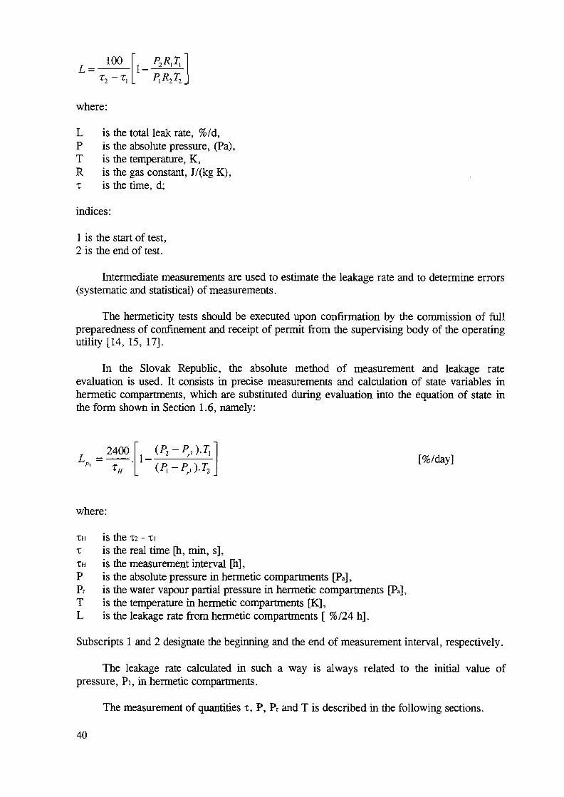
L_ 100 \l
T , - T , [ , 2 2 j
where:
L is the total leak rate, %/d,P is the absolute pressure, (Pa),T is the temperature, K,R is the gas constant, J/(kg K),x is the time, d;
indices:
1 is the start of test,2 is the end of test.
Intermediate measurements are used to estimate the leakage rate and to determine errors(systematic and statistical) of measurements.
The hermeticity tests should be executed upon confirmation by the commission of fullpreparedness of confinement and receipt of permit from the supervising body of the operatingutility [14, 15, 17].
In the Slovak Republic, the absolute method of measurement and leakage rateevaluation is used. It consists in precise measurements and calculation of state variables inhermetic compartments, which are substituted during evaluation into the equation of state inthe form shown in Section 1.6, namely:
?H1 —
2 4 0 0 - — - ' ' r̂ /̂ i
[%/day]
where:
XH is the T2 - TI
x is the real t ime [h, min, s ] ,XH is the measurement interval [h],P is the absolute pressure in hermetic compartments [Pa],Pr is the water vapour partial pressure in hermetic compar tments [Pa],T is the temperature in hermetic compartments [K] ,L is the leakage rate from hermetic compartments [ %/24 h ] .
Subscripts 1 and 2 designate the beginning and the end of measurement interval, respectively.
The leakage rate calculated in such a way is always related to the initial value ofpressure , Pi , in hermetic compartments.
The measurement of quantities x, P , Pr and T is described in the following sections.
40
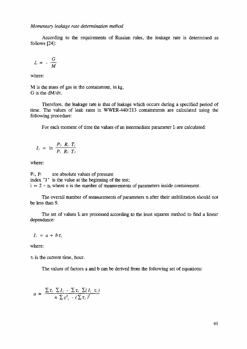
Momentary leakage rate determination method
According to the requirements of Russian rules, the leakage rate is determined asfollows [24]:
G
where:
M is the mass of gas in the containment, in kg,G is the dM/dT.
Therefore, the leakage rate is that of leakage which occurs during a specified period oftime. The values of leak rates in WWER-440/213 containments are calculated using thefollowing procedure:
For each moment of time the values of an intermediate parameter L are calculated:
/ , =
where:
In P,P'
Rt
Rj
Ti
Tj
Pi, Pi are absolute values of pressureindex " 1" is the value at the beginning of the test;i = 2 +• n, where n is the number of measurements of parameters inside containment.
The overall number of measurements of parameters n after their stabilization should notbe less than 9.
The set of values L are processed according to the least squares method to find a lineardependence:
/, = a + b%i
where:
Ti is the current time, hour.
The values of factors a and b can be derived from the following set of equations:
a~
41

n
n 2-r,- - (L?iJ
where:
n is the number of measurements of parameters.
The value of leak rate is calculated with the formula:
L = 100 (I + M)
where:
I is the a + 24b;AI is the total error of determination of the value of a complex parameter I
The statistical error of the determination of the value of the complex I is calculated withthe formula:
/.„ = tSJ- +Mn
where:
n(t0 - rcp) 2
jl(a + bri - hfs = i ~2
5,, =sj±
where:
TO is the time for which is a confidence interval determinedTav is the average timet is the Student-t distribution coefficient, determined on the basis of the number of
measurements, and of the value of confidence level a >0.95.
The systematic error ALys can be evaluated as:
AI,VV (A? AT
42
where:
AP, AR, AT are systematic errors.
The influence of the total error AI on the leakage rate can then be evaluated as follows:
if ALys/Ssi <0.8, then the systematic error can be neglected and the total error is equalto AL, ALi = t SM;
if ALys/Sst >8 , then the statistical error can be neglected and the total error is equal toAlsys;
if 0.8 < ALys/Sst <8, then the total error is given with the formula:
A/ = k, S
s = J - , 7 + (Sst tV 3k~->
with:
k2 - coefficient dependent upon the confidence interval (a = 0.95 fo = 1.1).ki - coefficient resulting from the formula:
A
7 '
+ AI,A/,.v.v
3kl
The values of a complex I which do not satisfy the inequality (a + b TI) < 2.3 S shouldbe excluded from consideration as rough misses.
Extrapolation of leakage rate in compliance with US rules
The extrapolation method by means of extrapolation factors was developed at the OakRidge National Laboratory [25].
According to this method, the total leakage value from hermetic compartments is acombination of various types of 'flow through' leaks.
Formulas for 'flow through' leaks have been developed based on thermodynamic lawsand research of flowing gases and vapours. Since leakage from hermetic compartments isexpressed in terms of a weight (or a percentage) proportion which leaks out per unit of time,formulas for various types of flow define the mass flow of the leaking medium.
43
The type of flow through a certain leak, and thus the character of leakage, depend onseveral factors, the most important being:
pressure (overpressure) and its critical values;the shape of the leak path;the type of leaking medium (composition of gaseous mixture).
In turn, these factors determine the type of flow:
laminar flow;molecular flow;turbulent flow;outflow dirough an orifice.
Formulas for all basic types of flow are given in Section 10.4.5.1 of Ref. [25].
During hermetic compartment leak tests at reduced overpressure, it is necessary toknow the relationship between pressure and leakage rate for various types of leaks which canoccur, i.e. to know the formulas defining leakage rate as a function of pressure.
Equations of leakage for all main flow types are provided in Section 10.4.6.2 of Ref.[25], which expresses leakage with laminar flow as:
LL = KL (P, - Pi, / P,)
where:
Pat is the atmospheric pressure = 0.1 MPa,Pi is the test pressure [MPa] (initial pressure of measurements),KL is the proportionality coefficient for laminar flow.
Extrapolation coefficients for individual flow types
When leakage formulas for all basic flow types are known based on the definition ofextrapolation factor, extrapolation coefficients for individual flow types can be derived.
The extrapolation factor can be defined as follows:
ef = Le pi
The extrapolation factor is a dimensionless ratio of leakage rate at extrapolationpressure Pe [MPa] to the leakage rate at reduced test pressure Pi [MPa].
Extrapolation coefficients for individual flow types are obtained by substituting theleakage rate ratio as a function of pressure in the relationship for pressure extrapolation.
Formulas of extrapolation coefficients for all basic flow types are given in Section10.4.6.2 of Ref. [25], which expresses the extrapolation coefficient for laminar flow as:
44
eL p, - Pi / p,
The extrapolation coefficient for critical outflow through an orifice is defined by:
(a) ?z, Pe <0.19MPa
n ( P / P f m j 0 5
[1 - ( fgt / r e ) J r p . „ jO.7!SII —I r / r^ i I
(b) Pz < 0.19 MPa, Pe > 0.19 MPa
0.259
(Pu, / Pz)0J!5 _ [1 -(PM
(c) Pz > 0.19 MPa, Pe > 0.19 MPA
eK = 1
Determination of the extrapolation factor
Extrapolation coefficients enable the definition of factors influencing a measuredleakage rate when it is extrapolated to a higher pressure than the test pressure (e.g. toaccident pressure), i.e. to determine the extrapolation factor.
The extrapolation factor can be determined by means of two methods:
(1) The first method is based on the assumption that it is impossible to conduct additionaltests at various pressure levels. In this case, the only option is to assume a flow typethrough leaks which offers conservative extrapolated values of leakage rate (e.g. thelaminar flow, which is the most conservative). In this case, the extrapolation factorwould equal the extrapolation coefficient of the laminar flow (extrapolation incompliance with DIN).
(2) The second method assumes implementation of several tests at various pressure levels.When analysing measured leakage rates by means of extrapolation coefficients ofindividual flow types, it is possible to select extrapolation coefficients of those flowtypes, which are closest to real extrapolation factors for tests implemented at variouspressures.
To determine the extrapolation factor in this study, the latter method has been used. Theextrapolation factor has been calculated based on analyses of leakage rates measured inWWER-440/213 units at the Bohunice and Dukovany NPPs at pressure levels of 50 and
45
100 kPa. From leakage rates measured at the above overpressures, real extrapolation factorshave been determined.
Based on analyses, it has been found that the flow character practically does not changewithin the whole range of pressures (30 to 150 kPa) and the decisive combination is laminarflow and outflow through an orifice. A comparison of the extrapolation curves for variousflow types with the real extrapolation curve shows that selection of extrapolation according tothe laminar flow would be overly conservative, and therefore to determine the extrapolationfactor, a proportion of both flow types was calculated for the resultant leakage.
The calculation was based on the solution of two equations with two unknowns:
K(o) + K (L) = L50
E(o) x K(o) + E(L) x K(L) = Lioo
where:
K(o) is the proportion of outflow through an orifice [%/day],K(L) is the proportion of the laminar flow [%/day],E(o) is the extrapolation coefficient for outflow through an orifice for extrapolation
from 50 to 100 kPa,E(L) is the extrapolation coefficient for the laminar flow for extrapolation from 50 to
100 kPa,L50, Lioo are the real leakage rates measured.
Solving these equations for leakage rate values measured at the Dukovany andBohunice-2 NPPs, the proportion of the laminar flow has been determined to be Kl = 0.3846and that of outflow through an orifice Kv = 0.6154 when extrapolating from an overpressureof50kPatol50kPa[17, 18].
The resultant formula of the extrapolation factor for extrapolation to a higher pressure(e.g. design pressure) of leakage rates measured at a reduced pressure is:
er = 0.3846 x E(L) + 0.6154 x E(o)
During pre-operational ILRTs at the Bohunice and Dukovany NPPs, the suitability ofindividual extrapolation coefficients and their proportion in the total extrapolation factor wereverified.
In Hungary, extrapolation is used to recalculate the leak rate measured at reducedpressure during periodical testing to leak rate at peak pressure. The basis for recalculation isthe experimental leakage rate plot of the unit measured at different pressure levels, includingthe peak pressure during pre-operational tests.
5.6.2. Pressure measurements
Absolute (or relative) pressure in hermetic compartments is measured by way of animpulse pipe leading from the SG compartment to the measurement room. All theinstrumentation for pressure measurements in hermetic compartments is connected to theimpulse pipe.
46
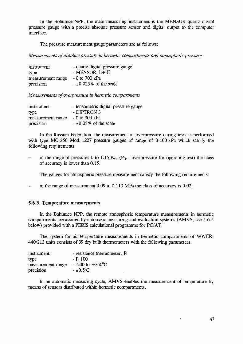
In the Bohunice NPP, the main measuring instrument is the MENSOR quartz digitalpressure gauge with a precise absolute pressure sensor and digital output to the computerinterface.
The pressure measurement gauge parameters are as follows:
Measurements of absolute pressure in hermetic compartments and atmospheric pressure
instrument - quartz digital pressure gaugetype - MENSOR, DP-IImeasurement range - 0 to 700 kPaprecision - ±0.025% of the scale
Measurements of overpressure in hermetic compartments
instrument - tensometric digital pressure gaugetype - DIPTRON 3measurement range - 0 to 300 kPaprecision - ±0.05% of the scale
In the Russian Federation, the measurement of overpressure during tests is performedwith type MO-250 Mod. 1227 pressure gauges of range of 0-100 kPa which satisfy thefollowing requirements:
in the range of pressures 0 to 1.15 Pop, (Pop - overpressure for operating test) the classof accuracy is lower than 0.15.
The gauges for atmospheric pressure measurement satisfy the following requirements:
in the range of measurement 0.09 to 0.110 MPa the class of accuracy is 0.02.
5.6.3. Temperature measurements
In the Bohunice NPP, the remote atmospheric temperature measurements in hermeticcompartments are assured by automatic measuring and evaluation systems (AMVS, see 5.6.5below) provided with a PERIS calculational programme for PC/AT.
The system for air temperature measurements in hermetic compartments of WWER-440/213 units consists of 39 dry bulb thermometers with the following parameters:
instrument - resistance thermometer, Pttype - Pt 100measurement range - -200 to +350°Cprecision - ±0.5°C
In an automatic measuring cycle, AMVS enables the measurement of temperature bymeans of sensors distributed within hermetic compartments.
47
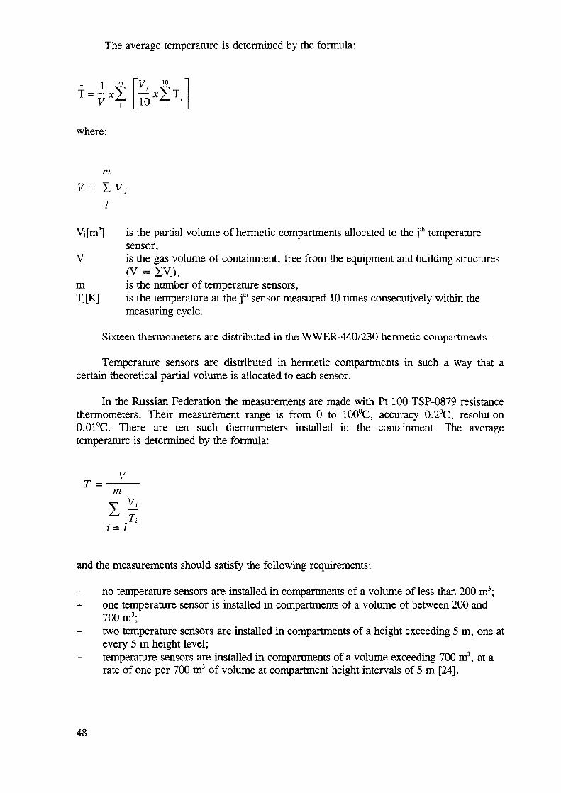
The average temperature is determined by the formula:
where:
m
Vj[m3] is the partial volume of hermetic compartments allocated to the j " 1 temperaturesensor,
V is the gas volume of containment, free from the equipment and building structures(V = I V J ) ,
m is the number of temperature sensors,Tj[K] is the temperature at the j * sensor measured 10 times consecutively within the
measuring cycle.
Sixteen thermometers are distributed in the WWER-440/230 hermetic compartments.
Temperature sensors are distributed in hermetic compartments in such a way that acertain theoretical partial volume is allocated to each sensor.
In the Russian Federation the measurements are made with Pt 100 TSP-0879 resistancethermometers. Their measurement range is from 0 to 100°C, accuracy 0.2°C, resolution0.01°C. There are ten such thermometers installed in the containment. The averagetemperature is determined by the formula:
VT =
m
and the measurements should satisfy the following requirements:
no temperature sensors are installed in compartments of a volume of less than 200 m3;one temperature sensor is installed in compartments of a volume of between 200 and700 m3;two temperature sensors are installed in compartments of a height exceeding 5 m, one atevery 5 m height level;temperature sensors are installed in compartments of a volume exceeding 700 m3, at arate of one per 700 m3 of volume at compartment height intervals of 5 m [24].
48
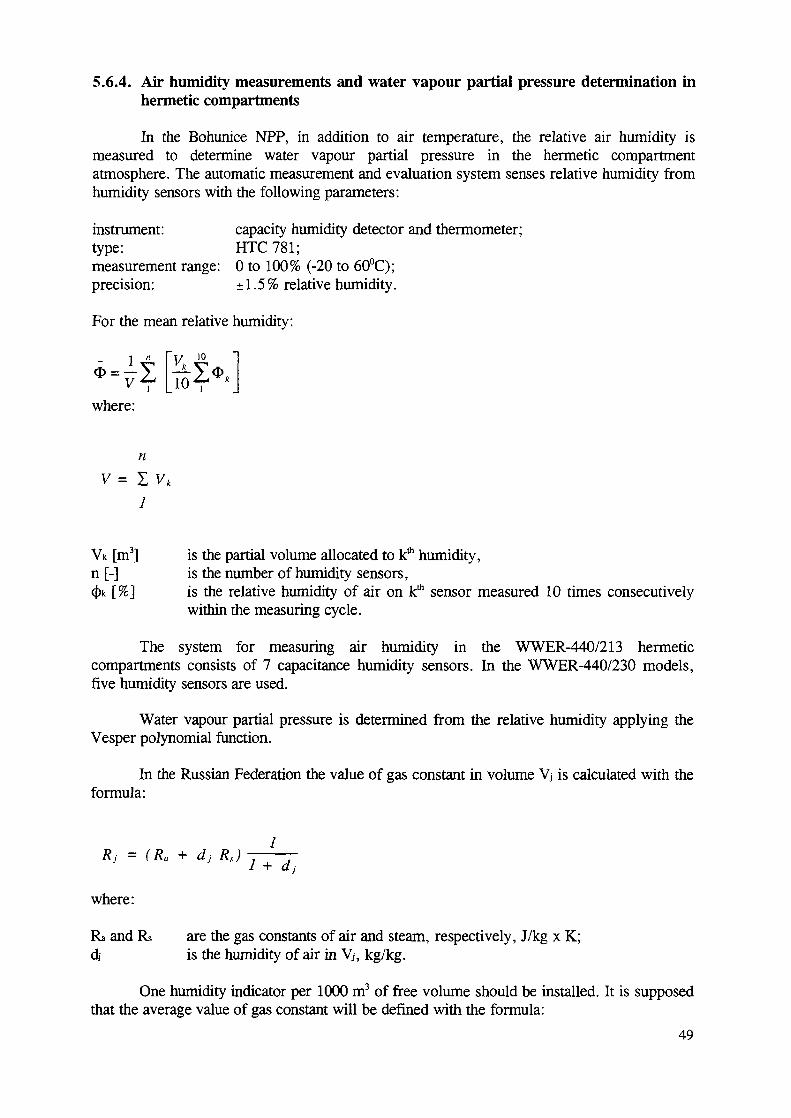
5.6.4. Air humidity measurements and water vapour partial pressure determination inhermetic compartments
In the Bohunice NPP, in addition to air temperature, the relative air humidity ismeasured to determine water vapour partial pressure in the hermetic compartmentatmosphere. The automatic measurement and evaluation system senses relative humidity fromhumidity sensors with the following parameters:
instrument: capacity humidity detector and thermometer;type: HTC781;measurement range: 0 to 100% (-20 to 60°C);precision: ±1.5% relative humidity.
For the mean relative humidity:
1 ^V i 10 1
where:
n
V = I Vk
1
VK [m3] is the partial volume allocated to k* humidity,n [-] is the number of humidity sensors,(j)k [%] is the relative humidity of air on k* sensor measured 10 times consecutively
within the measuring cycle.
The system for measuring air humidity in the WWER-440/213 hermeticcompartments consists of 7 capacitance humidity sensors. In the WWER-440/230 models,five humidity sensors are used.
Water vapour partial pressure is determined from the relative humidity applying theVesper polynomial function.
In the Russian Federation the value of gas constant in volume Vj is calculated with theformula:
1Rj = (Ra + dj Rx)
1 +
where:
Ra and Rs are the gas constants of air and steam, respectively, J/kg x K;dj is the humidity of air in Vj, kg/kg.
One humidity indicator per 1000 m3 of free volume should be installed. It is supposedthat the average value of gas constant will be defined with the formula:
49
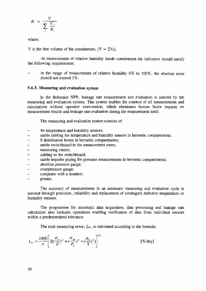
V
where:
V is the free volume of the containment, (V = SVj).
At measurement of relative humidity inside containment the indicators should satisfythe following requirements:
in the range of measurement of relative humidity 0% to 100%, the absolute errorshould not exceed 3 %.
5.6.5. Measuring and evaluation system
In the Bohunice NPP, leakage rate measurement and evaluation is assured by themeasuring and evaluation system. This system enables the conduct of all measurements andcalculations without operator intervention, which eliminates human factor impacts onmeasurement results and leakage rate evaluation during the measurement itself.
The measuring and evaluation system consists of:
46 temperature and humidity sensors;stable cabling for temperature and humidity sensors in hermetic compartments;8 distribution boxes in hermetic compartments;stable switchboard in the measurement room;measuring centre;cabling to the switchboard;stable impulse piping for pressure measurements in hermetic compartments;absolute pressure gauge;overpressure gauge;computer with a monitor;printer.
The accuracy of measurements in an automatic measuring and evaluation cycle isassured through precision, reliability and replacement of contingent defective temperature orhumidity sensors.
The programme for automatic data acquisition, data processing and leakage ratecalculation also includes operations enabling verification of data from individual sensorswithin a predetermined tolerance.
The total measuring error, Ler, is calculated according to the formula:
r i l /2
K = ^ 2 [A ) 2 + (^ - ) 2 + A ) 2 ] [%/day]
50
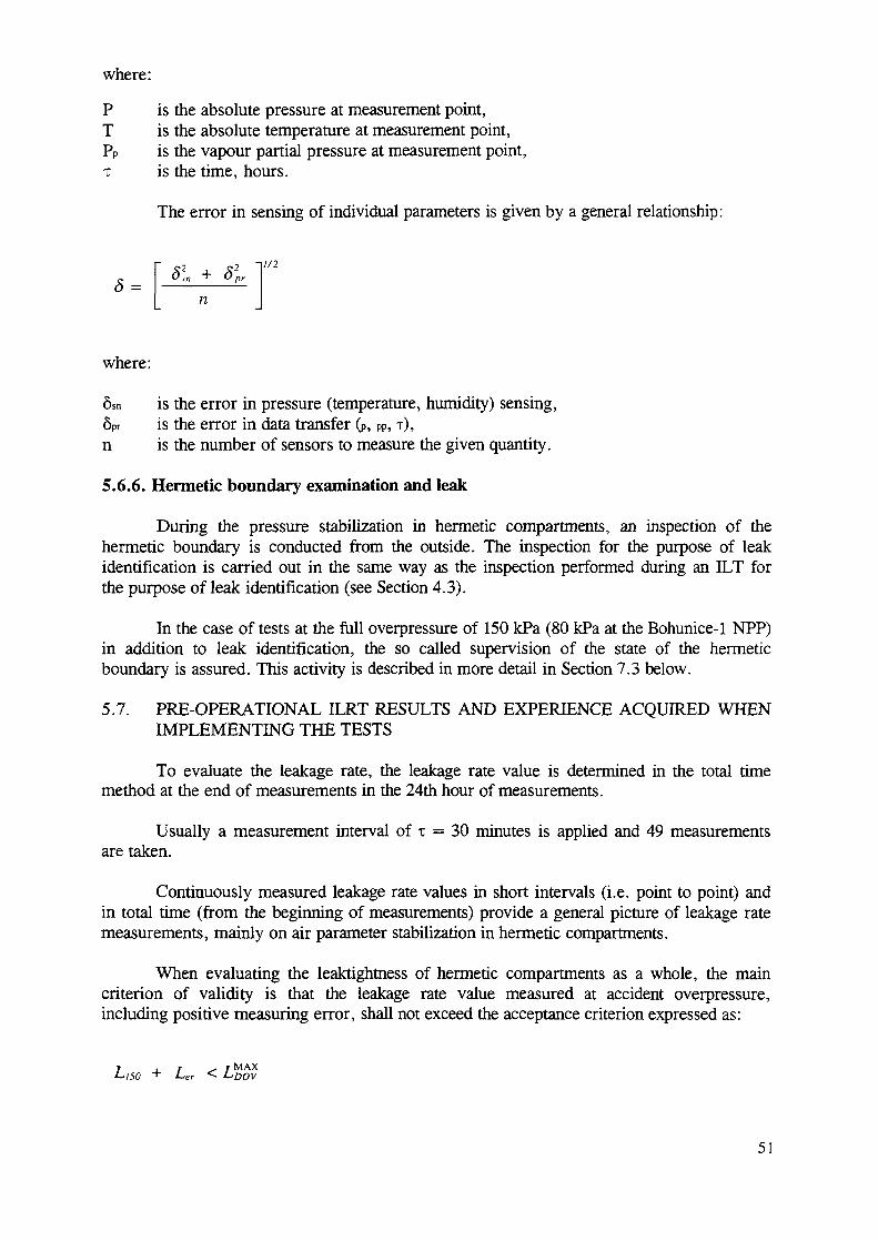
where:
P is the absolute pressure at measurement point,T is the absolute temperature at measurement point,PP is the vapour partial pressure at measurement point,x is the time, hours.
The error in sensing of individual parameters is given by a general relationship:
-|//2
s = * + *~~n
where:
8sn is the error in pressure (temperature, humidity) sensing,6Pr is the error in data transfer (P, PP, T),n is the number of sensors to measure the given quantity.
5.6.6. Hermetic boundary examination and leak
During the pressure stabilization in hermetic compartments, an inspection of thehermetic boundary is conducted from the outside. The inspection for the purpose of leakidentification is carried out in the same way as the inspection performed during an ILT forthe purpose of leak identification (see Section 4.3).
In the case of tests at the full overpressure of 150 kPa (80 kPa at the Bohunice-1 NPP)in addition to leak identification, the so called supervision of the state of the hermeticboundary is assured. This activity is described in more detail in Section 7.3 below.
5.7. PRE-OPERATIONAL ILRT RESULTS AND EXPERIENCE ACQUIRED WHENIMPLEMENTING THE TESTS
To evaluate the leakage rate, the leakage rate value is determined in the total timemethod at the end of measurements in the 24th hour of measurements.
Usually a measurement interval of x = 30 minutes is applied and 49 measurementsare taken.
Continuously measured leakage rate values in short intervals (i.e. point to point) andin total time (from the beginning of measurements) provide a general picture of leakage ratemeasurements, mainly on air parameter stabilization in hermetic compartments.
When evaluating the leaktightness of hermetic compartments as a whole, the maincriterion of validity is that the leakage rate value measured at accident overpressure,including positive measuring error, shall not exceed the acceptance criterion expressed as:
+ LCr < i-'DOV
51
for WWER-440/213 NPPs, or
L _i_ T ^ X MAX
SO "+" LtCr < JUDOV
for WWER-440/230 NPPs.
When measuring at a reduced overpressure level with a corresponding pressureextrapolation (as described in Section 5.6.1 above) the above criterion shall be met by theextrapolated leakage rate:
T , T ^ r M A X
Conditions for pre-operational ILRT programme application
The differences in WWER ILRT programmes vis a vis the requirements of App. J to10 CFR50 result from the principal differences between the hermetic compartments ofWWER-440/213 and 230 NPPs and the classical containments of PWR reactors in the USAand western Europe. The differences are:
Unlike the single cylindrical or spherical shape of western containments, WWERconfinements consist of a system of rectangular compartments mutuallyinterconnected by means of shafts and corridors;
The WWER-440/213 confinement consists of three main hermetic compartments: theSG compartment, the vent centre and the bubble condenser;
A hermetic liner is placed on the internal walls of the WWER-440/213 confinement;it also passes through walls and confines the SG compartment from outside. In floorsand ceilings it is covered with concrete;
In addition to air locks and penetrations, the WWER confinement is fitted withequipment hatches in the reactor hall where other hermetizing components are situatedsuch as the reactor cap and refuelling pool paddle (and, in the case of the 440/230,flaps), all of which are potential sources of leaks;
The WWER-440/230 confinement air locks are not designed as compact hermetizingunits but they represent separate rooms with internal hermetic liners; hermetic doorsare located not only on inlets and outlets but also between adjacent semi-accessiblecompartments;
At WWER-440/230 plants, the so-called gland penetrations are a major source ofleakages.
All these differences represent potential sources of leakages, and the leak rates ofWWER-440 hermetic compartments are some 100 times higher than the required values inPWR containments. The absolute (or reduced) pressure drop history in hermeticcompartments, with such leakages, cannot be considered as linear and when evaluatingleakage rates, western procedures of linear regression (mass point method in compliance withANSI/ANS or reduced pressure method in compliance with DIN) should be applied.
52

6. VERIFICATION INTEGRATED TESTS
6.1. AIMS
Precise determination of hermetic compartment leaktightness requires a high degree ofaccuracy in the parameters of leaking air as well as a high precision of the measuring andevaluation systems, calculational methods and computer codes used.
In spite of regular calibration of individual sensors and measuring instrumentation,there might be doubts as to the correctness of measured and calculated leakage rates fromhermetic compartments during the main pre-operational ILRT. Therefore, the calculationalprocedure and results of measurements are verified in some countries (Slovak and CzechRepublics) by means of the so-called verification integrated tests.
6.2. METHODS
In practice, three main types of verification tests can be applied:
verification test with zero calibration;verification test with flow rate measurements during depressurization;verification test with flow rate measurements during additional pressurization.
Zero calibration
Zero calibration is always implemented during preparations for the ILRT. This test isconducted with isolated hermetic compartments at an atmospheric pressure where a leakagerate of zero should be measured.
After preparatory work for the ILRT has been completed, the hermetic compartmentsare isolated from the outside atmosphere. Before pressurization, a few cycles ofmeasurements are carried out as for leakage rate evaluation.
Flow rate measurements during depressurization
This calibration procedure is applied after the measurements have been completedduring the main ILRT. The procedure is as follows:
completion of leakage rate measurements during the main ILRT;conversion of leakage rate to flow rate through leaks;gradual opening of the depressurization line bypass with installed flow meter;setting by means of a control valve the calculated flow rate to the same magnitude aswas the leakage rate value measured on the flow meter;stabilization of pressure and flow rates;measurement and leakage rate evaluation by means of measuring instrumentation, asfor ILRT.
Flow rate measurements during additional pressurization
In this instance the flow meter is installed in the pressurization line and the inflowingair has to compensate the leakage in such a way that the overpressure in hermeticcompartments remains stable. The remaining aspects are as described for flow ratemeasurements during depressurization.
53
6.3. VERIFICATION TEST EVALUATION
Zero calibration is evaluated based on leakage rate calculation as for ILRT at the testoverpressure.
At zero overpressure in hermetic compartments, the measured leakage rate shouldalso be zero with a certain tolerance:
Lo = 0 + allowable uncertainty [%/d]
Verification test with flow rate measurements during depressurization is evaluatedbased on comparison of the leakage rate set on the flow meter with the quantity by which theoriginal leakage rate measured during ILRT is increased.
The air flow rate which leaks from hermetic compartments through leaks during ILRTis calculated from the determined leakage rate (%/day) based on the known free volume ofhermetic compartments stated in the design specifications.
If the same flow rate is continually released from the hermetic compartments, theoriginal leakage rate measured during ILRT should be increased to a value two times higher:
LVT = 2-LILRT ± allowable uncertainties
The accuracy of this verification method depends to a considerable extent on theprecision of the flow meter as well as on the correct determination of the free volume of thehermetic compartments.
The procedure which consists in measuring the flow rate of inflowing pressurized airthat balances the integral leakages is similar, except for a different LVT:
LVT = 0 ± allowable uncertainties [%/d]
Note: this procedure is not to be considered a possible substitute for ILRT.
6.4. EXPERIENCE
'Zero' calibration tests are commonly used and their execution involves no problems.Tests with flow meters are rather complicated and were performed only once but with resultsthat were more than satisfactory: the criteria were met with negligible uncertainties.Moreover, there is a common confidence in the method presently used for ILRT, andtherefore there are no requirements for further application of these kinds of verification tests.
7. STRUCTURAL INTEGRITY TEST (SIT)
7.1. AIMS, PRINCIPLES AND FREQUENCY OF SIT
The aims of the SIT at WWER-440 NPPs are:
to verify the structural integrity of the hermetic compartments of WWER-440/213plants at a maximum test overpressure of 150 kPa or 1.15 x 150 kPa and of WWER-
54
440/230 plants at the opening pressure of the small safety valve (thus analyticallyconfirming their structural integrity at the design overpressure of 100 kPa);
to verify the strength of technological components of the hermetic boundary using theabove maximum test overpressure;
to verify the leaktightness of hermetic compartments at a maximum test overpressureand to determine the approximate value of leakage rates;
to localize all defects in hermetic boundary structural and technological componentsfor the purpose of repair.
An SIT is to be performed once in the lifetime of a unit (it is recommended anddesirable to do it during commissioning). After the SIT has been conducted, no further SITsare recommended during the operational life of the NPP. Experts are of the opinion that thedegradation of pertinent structural components (walls, technological elements) which couldimpact their integrity during DBA will not occur during the lifetime of the NPP.
The duration of an SIT is determined by the scope of the work to be carried out(inspections, measurements). In principle the time required does not exceed 3 hours.
7.2. INSPECTION METHODS AND MEASUREMENTS
Overpressure measurements in hermetic compartments
The instrumentation used for overpressure measurements in hermetic compartments isthe same as for ILRTs.
Measurements of wall deflection
Wall deformations are measured at the points specified by the designer.
For deflection measurements optical methods have mainly been used and they arefully satisfactory for this purpose.
Visual inspection and surveillance of hermetic boundary conditions
With regard to the scope of the preparatory work and especially owing to safetyreasons, the structural integrity test is the most demanding part of the hermetic compartmentintegrity tests.
The test at a maximum overpressure requires extra safety measures, protection ofinstrumentation and equipment and the presence of trained staff for hermetic boundaryinspection while the test is under way.
Special attention should be devoted to training staff for hermetic boundary inspection.Members of inspection teams are equipped with protective aids and positioned on individualfloors around the whole hermetic boundary at the respective unit.
55
Inspection teams fulfill two functions:
searching for leaks — up to 100 kPa;observation of deformations — above 100 kPa.
All inspection teams shall be provided with communication means and personalprotective aids. When the inspection teams are searching for leaks, they are provided withequipment needed for leak identification.
7.3. STRUCTURAL INTEGRITY TEST PROCEDURE
The SIT should be conducted shortly before the pre-operational ILRT or incombination with it; it always precedes the ILRT. This precedence also applies if the SIT isconducted as a complement to a periodical ILRT.
Pressurization
This procedure is the same as for the ILRT.
During the pressurization the following activities are implemented:
measurements of deflection at particular overpressure steps;measurements of overpressure;search for leaks;inspection of the hermetic boundary.
After the test pressure has been reached, pressurization is stopped.
Deflection measurements
With regard to SIT, deflection measurements are the most important stage of the testand therefore special attention should be devoted to them. Measurements are implemented bytrained staff of the authorized organization.
Contingent unallowable deflections shall be reported to the test supervisor.
It is good practice to carry out deflection measurements during depressurization at thesame overpressures as those at which they are measured during pressurization.
Hermetic boundary surveillance and inspection
This part of the test is crucial for the safety and success of the SIT procedure.
The activities of inspection teams, in which regulators are also expected to take part,start after every particular pressurization step has been reached and pressurization stopped.Inspection teams observe components and structure on pertinent segments of the hermeticboundary (in compliance with the SIT programme).
Leakage rate measurements
The approximate leakage rate is measured and assessed by applying the methods ofILRT or ILT for leak identification.
56
7.4. SIT EVALUATION
After processing the test results, the SIT is evaluated based on two criteria:
the structural integrity of walls, ceilings and floors, hermetic liner and hermeticboundary components is satisfactory if during the test none of these componentshave been impaired (no residual deformations or destructions have been found);the structural integrity of the building part is satisfactory if no deflections higherthan those specified in the design have been found.
Results of leakage rate measurements are compared with the maximum allowablevalue, thus providing an indication of the ILRT outcome.
8. CONCLUSIONS
8.1. REGULATORY AUTHORITIES' APPROACH
Licensing procedures, methods and limits for integral leakage rate testing for NPPswith WWER-440/213 reactors are well defined and implemented in all countries. For someNPPs with WWER-440/230 reactors, the methods used are less precise, mostly because ofthe high leakage rates found there. The work on the improvement of the leaktightness ofWWER-440/230 reactors will also make it possible to introduce essential improvements inthis area.
8.2. EXTRAPOLATION OF LEAKAGE RATE VALUES TO THE DESIGN PRESSURE
Regular leak rate tests are also performed at pressures lower than the designpressure. In such case, sufficient information should be available to justify extrapolation ofmeasured values to the full containment pressure. This information can be obtained duringplant leak rate tests and should include, inter alia, the contribution of various types of 'flowthrough' leakages to the integral value as well as the change of leakage size and flowcharacteristics. The extrapolation methodology should be verified by measurements at threedifferent pressures at least, including the containment design pressure. Analytical methodsare available for extrapolating a leakage rate measured at some lower pressure up to thedesign pressure value. Their application is not questionable, provided that they aresuccessfully verified by the actually measured leakage rate values at the extrapolatedoverpressures.
8.3. LOCAL LEAK RATE TESTS
There are many well developed and experimentally verified methods for local leakrate tests, used for type 'B' tests1. With regard to ' C tests, some ventilation system designsdo not allow for the implementation of methods used in western countries. This problemcan be solved by means of small backfitting measures. It is believed that this approach isfully feasible and can be successfully implemented.
8.4. LEAK IDENTIFICATION
In general, the experience accumulated in this area is good. The higher the integraltest overpressure used for leak rate testing, the better the conditions for the identification of
'Definition of "B" and "C" type tests is given in Section 1.2.
57
leakages. The major problem in this area seems to be the identification of 'inaccessible'leaks, i.e. located in inaccessible places or covered on both sides with concrete. Furtherefforts should be made to solve this problem.
8.5. STRUCTURAL INTEGRITY
For a number of reasons, it has not been possible to perform structural integrity testsat design or 1.15 design overpressures in some NPPs. This lack of test results can presentlybe compensated by combining calculational analyses with the results of measurements atseveral overpressure levels. However, the implementation of such an approach is subject tothe prior authorization of the regulatory bodies.
8.6. INTEGRATED LEAKAGE RATE TESTS (PRE-OPERATIONAL, PERIODICAL)
Differences in the structure and elements of confinements/containments in WWER-440 units and western PWR containments caused much higher leakage rates in the WWERunits than in western plants. Therefore the assumption commonly taken in western practicethat the containment pressure will remain constant during the integral leakage rate testingcannot be fully applied to WWER-440 reactors.
The practice of interpreting the results of leak rate measurements actually differ invarious countries. With respect to the WWER-440/230 and WWER-440/213 units in theCzech Republic, Hungary and Slovak Republic, the initial pressure PI is taken as thereference point, and the leakage rate measured over a period of time (during which thepressure is in effect decreasing from PI to a lower P2 value) is said to be "the leakage rate atthe initial pressure PI". In Bulgaria, the Russian Federation and the Ukraine, for bothWWER-440 reactor types, the instantaneous value of the leakage rate at pressure PI ismeasured and is called the "the leakage rate at the average pressure PI." The results aredifferent. The value of the discrepancy depends on the leakage rate, i.e. on the pressuredecrease during the test.
Both approaches are technically sound and can be logically explained. However, thedifferences outlined above make it impossible to compare the results directly among theplants in the various countries.
The containment leak rate is defined as the time derivative of the containment airmass at the constant design pressure divided by the total air mass in the containment. It isusually expressed in terms of relative change of the air mass in 24 hours time. Thecontainment leak rate for WWER-440 reactors should also be defined in accordance with thisdefinition. Since it is not possible to maintain the containment pressure constant during 24hours, the measurement of the leakage rate made in a shorter period of time, during whichthe pressure can be treated as constant, can be used for determining the leakage during 24hours.
58
REFERENCES
[I] INTERNATIONAL ATOMIC ENERGY AGENCY, General Design SafetyPrinciples for Nuclear Power Plants, A Safety Guide, Safety Series No. 50-SG-Dl l , IAEA, Vienna (1986).
[2] INTERNATIONAL ATOMIC ENERGY AGENCY, Safety Functions andComponent Classification for BWR, PWR and PTR, A Safety Guide, SafetySeries No 50-SG-D1, IAEA, Vienna (1979).
[3] INTERNATIONAL ATOMIC ENERGY AGENCY, Design of the ReactorContainment Systems in Nuclear Power Plants, A Safety Guide, Safety Series No50-SG-D12, IAEA, Vienna (1985).
[4] Containment and Confinement Performance in NPPs with WWER 440/213 andWWER 440/230 Reactors, Report of a Consultants Meeting, WWER-SC-085,Vienna, 29 November to 3 December 1993 (Report to the Steering Committee).
[5] Confinement Improvement Options for NPPs with WWER 440/230 Reactors,WWER-SC-101, Vienna, 10-14 July 1995 (Report to the Steering Committee).
[6] UNITED STATES NUCLEAR REGULATORY COMMISSION, PrimaryReactor Containment Leakage Testing for Water-Cooled Power Reactors, App.J., Title 10, Code of Federal Regulations, Part 50, Washington, DC (1991).
[7] AMERICAN NATIONAL STANDARDS INSTITUTE, Leakage Rate Testing ofContainment Structure for Nuclear Reactors, ANSIN45.4, La Grange Park(1972).
[8] AMERICAN NATIONAL STANDARDS INSTITUTE/AMERICAN NUCLEARSOCIETY, Containment System Leakage Testing Requirements, ANSI/ANS-56.8, La Grange Park (1987).
[9] GOSATOMNADZOR, Regulations on Construction and Operation ofContainment Safety Systems of NPPs PNAE-G-10-021-90, Moscow (1991).
[10] TECHY, Z., TAUBNER, R., BACSKO, G., "Leak rate measurements forWWER-440/213 confinements in Hungary", paper presented at the Mtg onMethods Used for WWER-440 Confinement/Containment Structural Integrity andLeak Rate Tests, IAEA, Vienna (1995).
[II] GESELLSCHAFT FUR ANLAGEN UND REAKTORSICHERHEIT (GRS)mbH, Integral Leakage Rate Testing of the Containment with the AbsolutePressure Method, Kerntechnischer Ausschuss (KTA) 3405, Issue 2/79 Germany(1979).
[12] ASSOCIATION FRANCAISE POUR LES REGLES DE CONCEPTION ET DECONSTRUCTION DES MATERIELS DES CHAUDIERES ELECTRO-NUCLEAIRES, Leaktightness and Resistance Tests of Containment, Part 3 ofRCC-G, "Design and Construction Rules for Civil Works of PWR NuclearIslands", AFCEN, France, July 1988 Edition.
[13] CZECHOSLOVAK ATOMIC ENERGY COMMISSION, Decree No 2 ofOctober 27, 1978, on the Nuclear Safety Assurance during Design, Licensing andthe Construction of a Building with a Nuclear Power Facility.
[14] CZECHOSLOVAK ATOMIC ENERGY COMMISSION, Regulation No. 436/90dated October 10th, 1990, on the Quality Assurance (QA) of Selected Equipmentwith Regard to Nuclear Safety of Nuclear Facilities.
[15] MINISTRY OF LABOUR AND SOCIAL AFFAIRS, LABOUR SAFETYAUTHORITY OF CZECH REPUBLIC, Ordinance of the Code on NationalTechnical Supervision over the Safety of Technical Equipment in the Field ofPower Engineering, 76 UBP/89 (1989).
59
[16] MINISTRY OF LABOUR AND SOCIAL AFFAIRS, LABOUR SAFETYAUTHORITY OF SLOVAK REPUBLIC, Ordinance of the Code on NationalTechnical Supervision over the Safety of Technical Equipment in the Field ofPower Engineering, SUBP 66/89 (1989).
[17] VASSIAGUINE, R.V., "Experience in conducting tests of accident localizationsystem (containment) in unit No. 1 of Rovno, NPP, Ukraine", paper presented atthe Mtg on Methods used for WWER-440 Confinement/Containment StructuralIntegrity and Leak Rate Tests, IAEA, Vienna, 1995.
[18] DEMIREVA, E., BALABANOV, E., "Test methods, results and neededmodernization for the improvement of WWER-440/230 confinementleaktightness", paper presented at the Mtg on Methods Used for WWER-440Confinement/Containment Structural Integrity and Leak Rate Tests, IAEA,Vienna, 1995.
[19] BALAZ, P., "Integrated tests of WWER-440 hermetic zones", paper presented atthe Mtg on Methods Used for WWER-440 Confinement/Containment StructuralIntegrity and Leak Rate Tests, IAEA, Vienna, 1995.
[20] PRANDORFY, M., "Local and individual tests of hermetic compartments ofWWER-440 NPPs conducted by VUEZ, Tlmace, Slovak Republic", paperpresented at the Mtg on Methods Used for WWER-440 Confinement/ContainmentStructural Integrity and Leak Rate Tests, IAEA, Vienna, 1995.
[21] RICANY, J., "Comments of the Nuclear Regulatory Authority of the SlovakRepublic on the methods used for determining leak rates from confinement",paper presented at the Mtg on "Methods Used for WWER-440Confinement/Containment Structural Integrity and Leak Rate Tests", IAEA,Vienna, 1995.
[22] LISKA, P., KADLEC, L., HATAS, J., KLEPAC, J., "Measurement of leak ratefrom the WWER-440 confinement, using a gas flow equation", paper presented atthe Mtg on "Methods used for WWER-440 Confinement/Containment StructuralIntegrity and Leak Rate Tests", IAEA, Vienna, 1995.
[23] HLINKA, M., KUCAK, L., URBAN, F., "Method of leak rate tests resultsevaluation", paper presented at the Mtg on Methods used for WWER-440Confinement/Containment Structural Integrity and Leak Rate Tests, IAEA,Vienna 1995.
[24] ANTOCHINE, V., VLASENKO, A., GRIGORIANTS, E., KOCHMANOV, E.,"Integral leak rate tests performance for WWER-440/230 confinements andWWER-440/213 containments", paper presented at the Mtg on Methods used forWWER-440 Confinement/Containment Structural Integrity and Leak Rate Tests,IAEA, Vienna, 1995.
[25] US Reactor Containment Technology, Oak Ridge National Laboratory Report,ORNL-NSIC-5 (1965).
60
ABBREVIATIONS
ANS American Nuclear Society (USA)ANSI American National Standards Institute (USA)BNSA Bulgarian Nuclear Safety AuthorityCFR Code of Federal Regulations (USA)CSKAE Czechoslovak Nuclear Regulatory AuthorityDBA design basis accidentDIN Deutsches Institut fur NormungGAN Nuclear Regulatory Authority in Russia or UkraineHVAC heating, ventilation, air conditioningHZ hermetic zoneI&C instrumentation and controlILT integrated leak testILRT integrated leak rate testLB LOCA loss of coolant accident following a large pipe breakLOCA loss of coolant accidentNPP nuclear power plantPWR pressurized water reactorRCP reactor coolant pumpRCS reactor coolant systemSG steam generatorSIT structural integrity testSWO RCS purification systemVNIIAES Russian scientific institute for NPPsVUEZ Power Engineering Research Institute at Tlmace, Slovak Republic
61
SYMBOLS
xH time in hoursAL uncertainty in the determination of LmA . M . any method approved by the regulatory bodydP/dt rate of pressure changeLo measured leakage rate at zero pressureLa permissible leak rate at pressure PaLace acceptance leak rate (%/24 h)Lmi leakage rate measured during test i (%/24 h)Lp1 leakage rate at pressure PiLpenet leak ra te of penetrationsLt m a x i m u m allowable leakage rate at Pt (%/24 h)LVT leakage rate during verification testMa specific mass of air under accident (LOCA) conditionsMe specific mass of air during experimentN S not specifiedPi initial pressure in the hermetic compartments at the start of the test time intervalP2 final pressure in the hermetic compartments at the end of the test time intervalPa peak accident pressure (design pressure) calculated for conditions inside
containment after DBAPm pressure measured during testingPt containment reduced test pressure selected to measure integral leakageTa air temperature within containment under accident (LOCA) conditions (K)Te air temperature during experiment (K)
62
Antochine, V.
Bachko, G.Badez, N.Balabanov, E.Balaz, P.Grigoriants, E.
Klepac, J.Kochmanov, E.
Kucak, L.Liska, P.Pflug, V.Prandorfy, M.Ricany, J.Strupczewski, A.Tecsi, Z.Tkac, A.Urbancik, L.
Vassiaguine, R.
CONTRIBUTORS TO DRAFTING AND REVIEW
Scientific & Engineering Centre for Nuclear Radiation Safety,Russian FederationNPP Paks, HungaryElectricite de France, FranceNuclear Safety and Automation Div., Energoproekt, BulgariaVUEZ Tlmace, Slovak RepublicAtomtechenergo, Ministry of Russian Federation for NuclearEnergy, Russian FederationVUJE, Nuclear Power Plant Research Institute, Slovak RepublicAtomtechenergo, Ministry of Russian Federation for NuclearEnergy, Russian FederationSlovak Technical University, Slovak RepublicVUJE, Nuclear Power Plant Research Institute, Slovak RepublicSiemens AG, GermanyVUEZ Tlmace, Slovak RepublicNuclear Regulatory Authority, Slovak RepublicInternational Atomic Energy AgencyVEIKI, HungaryVUJE, Nuclear Power Plant Research Institute, Slovak RepublicNuclear Safety Inspector Resident, Dukovany NPP, CzechRepublicKiev Institute Energoproekt, Ukraine
Consultants Meeting
Vienna, Austria: 8-12 May 1995
63