x. appendix a - st. columba's episcopal church was provided by a steam boiler and steam...
TRANSCRIPT
4733 Bethesda Avenue 301.652.8550 (Tel) Suite 550 301.652.1999 (fax) Bethesda, Maryland 20814 www.shinberglevinas.com
Appendix A X.
Potomac Energy Group – Report dated 2009
118 of 192
EVALUATION OF EXISTING MEP SYSTEMS
PREPARED
FOR
4201 Albemarle Street
Washington, D.C. 20016
PREPARED
BY
POTOMAC ENERGY GROUP, INC. 20 S. Quaker Lane
Alexandria, Virginia 22314
June 24, 2009
119 of 192

Potomac Energy Group, Inc. 1.2
Table of Contents Objective ............................................................................................................................................Page 1.3 Building History ................................................................................................................................Page 1.3 Executive Summary ..........................................................................................................................Page 1.4 Existing Systems Descriptions ..........................................................................................................Page 1.5
Mechanical Systems .................................................................................................................Page 1.5 Heating ....................................................................................................................................Page 1.5
Cooling .....................................................................................................................................Page 1.5 Exhaust .....................................................................................................................................Page 1.5 Areas of Concern ......................................................................................................................Page 1.5 Recommendations ....................................................................................................................Page 1.7 Table 1- Comparison of Qualitative/Subjective Issues ...........................................................Page 1.10 Table 2- Building System Evaluation Form ...........................................................................Page 1.11
Existing Electrical Systems ..............................................................................................................Page 1.12
Normal Power Systems ...........................................................................................................Page 1.12 Emergency Power Systems .....................................................................................................Page 1.12 Fire Alarm System ..................................................................................................................Page 1.13 Lighting System ......................................................................................................................Page 1.13 Telephone System ..................................................................................................................Page 1.13 Security System ......................................................................................................................Page 1.14 Exterior ...................................................................................................................................Page 1.14 Observations ...........................................................................................................................Page 1.14 Recommendations ..................................................................................................................Page 1.14
Existing Plumbing Systems ..............................................................................................................Page 1.16 Gas Service .............................................................................................................................Page 1.16 Domestic Hot Water ...............................................................................................................Page 1.16 Fire Protection Service ...........................................................................................................Page 1.16 Plumbing Fixtures ..................................................................................................................Page 1.16 Recommendations ..................................................................................................................Page 1.16
Cost Estimates ..................................................................................................................................Page 1.18 Attachment A- Proposed Systems Descriptions ...............................................................................Page 1.20 Attachment B- Photographs .............................................................................................................Page 1.23 Attachment C- Overall Floor Plans ..................................................................................................Page 1.27
120 of 192

Potomac Energy Group, Inc. 1.3
Objective
An overall study of th lectrical and plumbing systems. Address areas of concern, in terms of life safety, efficiency and remaining life of the
systems. Assist the church with prioritization of systems upgrading to achieve the following:
! Improve the building indoor environment comfort ! Improve efficiency of the mechanical systems ! Re-use the existing systems where feasible ! Replace and upgrade systems that have passed their useful life
Building H istory The original building was built in 1957 and included the Sanctuary and South Wing Office Building (it appears that the sanctuary was built earlier). The Parrish Hall and North Wing Classrooms were added in 1988. The original building did not have an air conditioning system. Heating was provided by a steam boiler and steam convectors. Disclaimer The evaluations, cost estimates, and descriptions of existing systems included within this report are based on visual examination of selected areas of the existing building. The information contained within this report is based on a series of site surveys conducted by representatives of Potomac Energy Group (PEG) during the months of March and April 2009. The engineering team did not dismantle or conduct tests on building materials, components, or equipment to identify material compositions, evaluate hidden conditions, or inspect working parts. This report represents our experienced judgment. The report is limited by nature of our surveys and inspection of the building at the St. s Church.
121 of 192
Potomac Energy Group, Inc. 1.4
Executive Summary The facility HVAC systems consist of various types and ages. The oldest systems is the steam system which is over fifty years old. The newest system will be the rooftop units that are being installed at the time of preparation of this report. The rooftop units are replacements for the sanctuary existing air conditioning system. There are other systems that were installed in 1988 to serve ______ and ______. Due to the poor condition and age of the systems, the church is in a critical moment in terms of decision making for the upgrading of the systems. Repair and patching of the existing system will become extremely costly and operational cost of the system due to inefficiency of the systems will rise as well. In order to assist the church, PEG has considered multiple options for upgrading however, for various reasons some of the systems could not be proven feasible. Refer to Table 1 for comparison Based on Table 1, improvement and expansion of one of the existing systems (hydronic 2-pipe) surfaced as the most feasible system. Therefore, the report is mainly prepared around the hydronic 2-pipe system. One of the main reasons this system stands up as the most viable systems is due to the existence of hot/chilled water distribution piping thorough out most of the building which is a real value since the piping has over 15 years effective life remaining.
122 of 192

Potomac Energy Group, Inc. 1.5
Existing Systems Description
Mechanical Systems
Heating Heating is served by two steam boilers and one hot water boiler for most parts of the building. The steam boilers provide steam to radiators in the Sanctuary and to (steam to hot water) heat exchanger which serves hot water radiators in the south wing. The hot water boiler serves the fan coil units and air handling units to the rest of the building via a dual (2-pipe) pipe system with the exception of the Auditorium. The auditorium heating is provided by two gas fired rooftop units. Cooling The south wing and north wing with the exception of the auditorium are served by an 80 ton air cooled chiller via a 2-pipe system. The auditorium cooling is provided by two rooftop units. The sanctuary cooling is provided by a 30 ton split system. (Sanctuary proposed to be conditioned by
Exhaust The bathrooms exhaust is served by individual ceiling mounted exhaust fans. The kitchen hood exhaust is served by a roof mounted exhaust fan. There are a few fans that exhaust air from corridors. A reas of Concern
1. The cooling and heating in the North Classroom Building is served by fan coil units with almost no or limited ventilation. There are slots through the wall (Brick Vents) in some of the FCUs that can bring limited outside air which is not adequate for the classrooms.
2. There is continuous exhaust from the corridors which will create negative pressure in the building. This can result in unconditioned outside air entering the building through the doors. In addition, under current codes egress corridors shall not be used for air movement.
3. Most of the equipment/units are at the end of their useful life (see evaluation spread sheet).
4. The steam boilers with its associated piping and controls are in poor condition and need to be replaced.
5. There are multiple water leaks from piping and equipment in the boiler room. We verified
a leak from one zone pump at the time of the site visit. The boiler room floor is wet and
123 of 192
Potomac Energy Group, Inc. 1.6
can pose a safety hazard.
6. Fire dampers were not installed in the ducts in some or all corridor wall penetrations in South Wing. This is based on only a few locations field verified.
7. Heating in the nursery (level 1 south wing) is provided by the AHU located above the ceiling with supply and return grilles at the ceiling. There are no means of providing heat at the floor level. This arrangement is not adequate to provide heat close to the floor where children sit. The heated air supplied will be returned at high levels before it reaches the floor which will result in cold floors.
8. Fan coil units are equipped with 2-way control valves to open or close according to thermostats set point. There is an additional 1/4 tube bypass between supply and return chilled/hot water pipes. This arrangement will ensure water return to the central pump however; it may reduce the flow in the fan coil units when full flow is needed.
9. There is no water treatment station provided for hot/chilled water system. The lack of water treatment results in scale build up, corrosion and deterioration of pipes and coils.
10. tunnel to the side wall louver in the areaway- The tunnel is just an excavation through the dirt. Water in the boiler room leaks into this tunnel creating an environment in which mold can grow.
11. Fin tube radiators that serve the music classroom are inside closets which will isolate the heat and prevent heat transfer to the room.
12. The building (excluding the sanctuary) is under severe negative pressure. Total exhaust quantity - excluding the kitchen and elevator machine room is 6350 cfm. Total outside air quantity is 2365 cfm.
13. The existing air cooled chiller appears to be functioning properly. However it is close to
the end of its remaining useful life. 14.
create low head room.
124 of 192

Potomac Energy Group, Inc. 1.7
Recommendations As indicated in table 2 almost all of the existing HVAC system major components will reach or pass their expected useful service life within five (5) years. Due to this condition, we have taken a holistic approach toward the HVAC systems upgrading. With this approach the church has two options:
1. Repair, replace and upgrade the existing systems and systems components on an as needed basis.
2. Upgrade the existing systems in two or three phases with the most efficient and state of the art systems.
Option 1 does not require large sums of money since the repairs and replacements can be done at various times in smaller increments in the span of five or so years. This option reduces the opportunity for innovative design and forces the continuation of existing systems. Option 2 on the other hand, targets a larger portion of the building systems at a time which requires larger sums of money. However, it opens the door for partial or complete replacement of some or all of the existing systems with more efficient systems. If option 1 is selected we recommend the following to be implemented. The items are listed in the order of priority and completed in five (5) years:
A. Replace and upgrade the Sanctuary cooling and heating systems. A separate report has been submitted for this task and a 25 ton gas fired rooftop unit with three supplemental systems option has been selected.
B. Replace the two steam boilers with high efficiency hot water boilers to provide heat for
the entire hot water system in the building including heating zones which will be separate from the 2-pipe (dual systems). Modifications in the hot water system can be as follows:
a. Remove steam systems in boiler room and modify piping to provide hot water to the existing zone pumps. This will include removing the steam condensate pump, the heat exchanger and steam piping.
b. Run two new hot water supply and returns to the new hot water radiators in the Sanctuary. A new zone pump will be required.
c. The two new hot water boilers shall be sized adequaltye to eleiminate the need for the existing hot water boiler. The boilers should be used to support heating in the dual pipe systems when the existing Lochinvar boiler reaches at the end of its useful life and needs to be removed.
C. Replace steam radiators in the Sanctuary with hot water radiators. New hot water piping
will be required.
125 of 192

Potomac Energy Group, Inc. 1.8
D. Replace in kind one main hot water pump (in two pipe system). E. Repair all water leaks in the boiler room.
F. Existing corridors exhaust systems need to be eliminated and air balance test shall be
performed.
G. A new Make-up Air Unit with small size ductwork will be required to provide adequate code required ventilation for classrooms in the north building. This will also make up for the toilet exhaust and will keep the building slightly pressurized.
H. We performed a block load calculation for the areas served by the chiller and found out
that the existing chiller is oversized. If the chiller is replaced the new chiller can be the same size and it still can handle additional loads required by added ventilation.
I. We recommend keeping the dual (2-pipe) system. The conversion to a 4-pipe system is
beneficial for better temperature control in individual rooms but the cost would be very high.
J. The existing bypass line between chilled/hot water supply and return at each FCU shall be closed. This will result in variable water flow in the system depending on the 2-way control valve position at each FCU. The new central pumps can be on variable frequency drive (VFD) to provide water flow as needed to fan coil units which will save considerable energy.
K. The existing fan coil units in North Wing classrooms shall remain and be re-used. We
recommend the replacement of FCUs to be done on an as needed basis by maintenance personnel based on the condition and the performance of FCUs.
L. Office and Kindergarten Building (South Wing):
a. Provide a low return grille by adding a chase to bring air to AHU located above
the ceiling or add baseboard fin tube (electric) radiators in the basement. This arrangement will improve comfort and provide heat close to the floor where children sit.
b. Modify control systems and air distribution in areas where individual room
temperature control is not adequate. This can be achieved by several methods including addition of zone dampers, variable air volume diffusers (Therma-fusers) and relocation of thermostats. Those modifications will not be required if the Fan Coil Units option is pursued ( See General, item 1- f )
c. Install fire dampers in all existing duct penetrations thru the corridor rated walls.
If the building will be sprinklered, fire dampers will not be required.
126 of 192

Potomac Energy Group, Inc. 1.9
M. Replace all existing equipment that passed its useful life (see evaluation table). This will include the following:
a. Kitchen exhaust fan and make-up air units. b. All bathroom exhaust fans and re-size for current code requirements. c. RTU-1 and RTU-2 that serve the auditorium. d. Chiller. e. Pump serving hot and chilled water. f. All ceiling c
secondary drain pan, controls, etc. This may be difficult due to limited space above ceiling.
N. Provide new Building Automation System (Web Based) with central station to execute the following functions.
a. Monitoring and adjusting zone temperatures. b. Systems operation 24/7 time scheduling for Occupied and Unoccupied Modes. c. Alarms. O. Provide CO2 sensors/ controller in the auditorium to control the outside air according to occupancy levels.
If Option 2 is selected we recommend the following:
A. Provide 2-pipe fan coil units or VRV systems in the offices and classrooms of the South Wing. Remove air handling units and re-use the ductwork for fresh air distributions in conjunction with a 100% fresh air unit.
If VRV is chosen, the replacement boiler and chiller shall be reduced in size since hot and chilled water will not be used in the South Wing.
B. If 2-pipe system does not provide the desired comfort level in the North and South
Wings, use of a 4-pipe systems or VRV systems are recommended.
If VRV system is selected in both wings, use of boiler and chiller will be reduced significantly.
127 of 192

Potomac Energy Group, Inc. 1.10
!"#$%&'(&)*+,"-./*0&*1&23"$.4"4.5%673#8%94.5%&.//3%/:&*,4.*0/&':;:<&=&>!"#$%&'()(*+,-#.(#/()0(*1/2-#.
?,4.*0/
@+,"94/
34#$/%(5()(6(768$4,(9/#("%:(;<$==,:(1"#,2(>?-#,@
34#$/%(576(1"#,2(>/A2B,(9,"#(8A@4(CD;//=$%&(E/C,2
34#$/%(5F(6(G!G(-?-#,@
34#$/%(5H(6(I,/#<,2@"=(>?-#,@(;=/-,:(J//4
34#$/%(5K(6(H(4$4,(</#("%:(B<$==,:(C"#,2(-?-#,@
LM$-#$%&(;/%:$#$/%
N%$#$"=(+A:&,# F O P )0 P )34,2"#$/%(+A:&,# H H F 7 K OQ"$%#,%"%B,(+A:&,# H H H H K )0J,"-#(:$-2A4#$/%(#/(/BBA4"%#-(:A2$%&(B/%-#2AB#$/% 7 R K P R )N%://2(,%S$2/%@,%#(B/@T/2# H ) ) ) ) )0;/%#2/==$"U$=$#?(/T(#,@4,2"#A2, H ) ) ) ) )0>?-#,@(=$T, H F F F F )03A#://2DN%://2(>4"B,(!,VA$2,@,%# 7 7 F )0 7 )E/#"=(*=/C,2(-B/2,($-(U,##,2. 7R F0 7P H0 FF K) Note: The following systems were not included in this comparison due to their major and costly
disruption to the existing building finishes and structure. * Packaged Rooftop Units: This system requires roof space which is not available on the North
Wing and large duct chases from the roof to the first and basement levels which will impact the existing building finishes, floor area, and the building structure.
* Split DX Units: This system requires mechanical closets for indoor units which will take away
floor area and ground or roof area for outdoor units. This system is also less efficient and has a shorter life than the rest.
128 of 192

Potomac Energy Group, Inc. 1.11
129 of 192

Potomac Energy Group, Inc. 1.12
E lectrical Systems
E X IST IN G SYST E MS D ESC RIPT I O N
Normal Power Systems
The original building was built around 1957 and the electrical service equipment which was installed at the time this building was built is rated at 400 Amps, 3 phase, 4-W, 120/208 Volt. A Sanctuary addition including the Lobby and Auditorium Hall area was added in 1988. During the 1988 addition the electrical service has been upgraded to 1600 Amps, 3 phase, 4-W, 120/208 Volt. This newer service backfeeds the original 800A service equipment. During that time the original incoming service to the building was disconnected. A new incoming underground electrical service lateral was brought into the building. It originates from an underground transformer vault owned and maintained by PEPCO utility power company along Albermarle street. at the front side of the Church. Service conductors from the secondary side of the vault mounted transformers terminate in the C/T (current transformer) section of a 2 section switchboard located in the Main Electrical Room at the Basement level.
The distribution section of the switchboard have the following service breakers: one (1) 3P-400A main service breaker which backfeeds the original 400A main distribution panel MDP1, one (1) 3P-800A main service breaker which feeds the newer 800A MDP, and one (1) 3P-800A main service breaker feeding the Chiller opposite the exterior wall. The building is centrally metered by Potomac Electric Power Company (PEPCO) with one utility meter (meter # K-23QRY31192T). This utility meter is located in the Basement in the Main Electrical Room. Emergency Power System
There is no emergency generator to serve the life safety loads i.e. emergency and exit lights for the building. The service emergency switches which are located adjacent to the switchboard in the Basement Level sits on a wiretrough which is tapped ahead of the main service breakers at the switchboard. One switch feeds an adjacent emergency panel and the other switch feed the fire alarm control panel. Exit lights with battery back-up and some emergency lights are present in the original 1957 building, although some exit lights are not lit. Although there are exit lights with test switches , there are no visible emergency lights in the Auditorium Hall. The emergency and exit lights coverage in this area of the building the well as the 1988 addition and even in the Chapel area are minimal and needs to be evaluated further specially along the egress paths. With the exception of the Music Room, the overall building coverage for emergency and exit lights are minimal and not up to current Codes.
130 of 192
Potomac Energy Group, Inc. 1.13
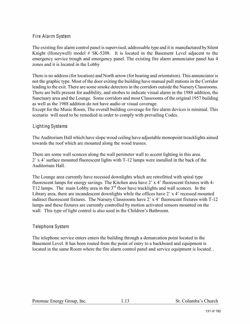
F ire A larm System The existing fire alarm control panel is supervised, addressable type and it is manufactured by Silent Knight (Honeywell) model # SK-5208. It is located in the Basement Level adjacent to the emergency service trough and emergency panel. The existing fire alarm annunciator panel has 4 zones and it is located in the Lobby There is no address (for location) and North arrow (for bearing and orientation). This annunciator is not the graphic type. Most of the door exiting the building have manual pull stations in the Corridor leading to the exit. There are some smoke detectors in the corridors outside the Nursery Classrooms. There are bells present for audibility, and strobes to indicate visual alarm in the 1988 addition, the Sanctuary area and the Lounge. Some corridors and most Classrooms of the original 1957 building as well as the 1988 addition do not have audio or visual coverage. Except for the Music Room, The overall building coverage for fire alarm devices is minimal. This scenario will need to be remedied in order to comply with prevailing Codes. L ighting Systems The Auditorium Hall which have slope wood ceiling have adjustable monopoint treacklights aimed towards the roof which are mounted along the wood trusses. There are some wall sconces along the wall perimeter wall to accent lighting in this area.
-12 lamps were installed in the back of the Auditorium Hall. The Lounge area currently have recessed downlights which are retrofitted with spiral type fluorescent lamps for energy sav -T12 lamps. The main Lobby area in the 3rd floor have tracklights and wall sconces. In the
ind -12 lamps and these fixtures are currently controlled by motion activated sensors mounted on the
throom.
T elephone System The telephone service enters enters the building through a demarcation point located in the Basement Level. It has been routed from the point of entry to a backboard and equipment is located in the same Room where the fire alarm control panel and service equipment is located. .
131 of 192

Potomac Energy Group, Inc. 1.14
Security System
Currently the building have a security system control panel located in the Basement Level. It is manufactured by Vykon Security. A security keypad is installed at the same wall to arm the system. The extent of the security system coverage has not been field verified at the time this survey was done. Exterior
The building have wall mounted exterior security lights at the front and back entrances, as well as on the side of the building.. The type of fixture varies in appearance but appears to have H.I.D. (high intensity discharge) lamps. Some canopy lights are also provided with cylinder type downlights. Along the Butterworth street which is on the poles in the parking lot. At the corner of Albermarle street and 42nd street, which is the frontal side of the Church, there are some cobra head pole mounted lights. Observations:
The electrical service equipment is original to the building. All feeders (conductors) from the service switches to the panel are installed in EMT (electrical metallic conduit) and terminated with mechanical lugs. The grounding system is not visible at the service equipment at the time survey was performed. The integrity and reliability of the service grounding need to be tested (measured). There are notable Code violations in this Church building.
The electrical room has been used as storage thereby impeding the Code required clearance of the service equipment/panels.
Emergency lighting and exit lighting, some do not have battery back-up is inadequate for safe egress of people in case of emergency.
Fire alarm system coverage is inadequate and not up to current Codes. Recommendations
1. Emergency System Recommendation It is recommended that exit lights need to be replaced with a more reliable and energy efficient types such as panel face with LED lamps, and additional emergency lighting with battery back-up capability need to be added along the path of egress and where required by Codes. Additional emergency and exit lights with battery back-up will need to be added for proper coverage and in compliance with current Codes. Exit lights shall be visible along path of egress, located no more
132 of 192

Potomac Energy Group, Inc. 1.15
than 100 feet distance and emergency lights with battery shall have a minimum light level of 1 footcandle along the path of egress as well. Battery backup shall have a minimum of 90 minutes back-up capability to safely and adequately exit people out of the building during normal power failure. 2. F ire A larm System Recommendation The existing fire alarm system is recommended to be upgraded. The control panel will need
to be evaluated further if there is spare capacity. New NAC (Notification appliance circuit) panels will be required to accept new devices. New devices will need to be added specially in the original building and Sanctuary areas. Horns for audibility and strobes for visual annunciation will be provided throughout the building with coverage to comply with current codes and with the American with Disabilities Act (ADA).
The existing fire alarm annunciator panel (FAAP) will need to be replaced to show proper information/zoning and as per Fire Marshallneed to be evaluated.
3. E lectrical Service Upgrade Recommendation The existing capacity of the service will need to be evaluated as future load i.e. new
Sanctuary lighting/dimming system, new HVAC is anticipated. A building addition if contemplated will also necessitate and/or trigger an electrical service increase. This will require a new Main Electrical Room, coordination with PEPCO Power Utility, etc. if this scenario is anticipated.
4. L ighting System Recommendation
It is recommended that lights need to be replaced with more energy efficient types such as fluorescent lights with T-8 lamps and to be controlled with occupancy sensors for energy savings. Auditorium and Worship area need to have new lights and is recommended to have a dimmer system for functionality.
133 of 192

Potomac Energy Group, Inc. 1.16
Plumbing Systems
Existing Systems Description
Gas Service
the buildi
Domestic Hot Water
The building has two gas fired water heaters located in the boiler room. One water heater (100 gallons) serves the kitchen only and the other water heater ( 74 gallons) serves all the other fixtures in the building. Both water heaters are in good condition. F ire Protection Service
The existing fire protection servic
and routes to the standpipes in the building. The fire department connection does not have a check valve, however, it does have a shutoff valve which is chained and locked in the closed position.
Plumbing F ixtures
The existing plumbing fixtures in the building are a mixture of flush tank toilets and flush valve toilets. The fixtures we visited appear to be working properly, however not all toilet rooms had ADA accessible toilet fixtures. None of the toilet rooms we visited had insulation or knee guards on the lavatory traps which could cause an injury for wheel chair users. Recommendations
F ire Protection Service
The fire service room should be cleared of all storage items. These items will be a hazard in the event of an emergency. The fire department connection has a shutoff valve which is chained and locked in the closed position on the inside of the fire pump room. If the fire department needs to pump water in to the building by utilizing the fire department connection, the water would not make it to the fire protection system. We suggest replacing this chained, locked shut off valve with a check valve.
134 of 192

Potomac Energy Group, Inc. 1.17
Domestic Hot Water
to the age of the water heater units.
Plumbing F ixtures
The plumbing fixtures in the building designated for ADA use should receive knee protecting insulation.
135 of 192

Potomac Energy Group, Inc. 1.18
Cost Estimate:
1. Replace Steam Boilers, remove steam system, and install new hot water piping: $ 250,000.00
2. Replace Steam radiators in the Sanctuary $ 30,000.00
3. Replace in kind one main chilled/hot water pump. $ 8,000.00
4. Repair all water leaks in the boiler room. $ 5,000.00
5. Eliminate corridors exhaust and perform air balance test. $ 10,000.00 6. Install new Make-up Air Unit for classrooms in the north building. $ 50,000.00 7. Install fire dampers in all existing duct penetrations thru the corridor rated walls. $ 20,000.00
8. Eliminate the bypass line in each existingFCU and install VFD in the chilled /hot water
pump. $ 25,000.00
9. Kitchen exhaust fan and make-up air units. $ 20,000.00 10. Bathroom exhaust fans. $ 8,000.00 11. RTU-1 and RTU-2 serving the auditorium. $ 30,000.00 12. $ 50,000.00 13. Chiller. $ 80,000.00 14. Hot/chilled water standby Pump $ 6,000.00
15. Provide new Building Automation System. $ 50,000.00 16. Fan Coil Units in the south building ( Approx 30 FCUs) $ 120,000.00 17. Upgrade Fire Alarm. $ 70,000.00
136 of 192
Potomac Energy Group, Inc. 1.19
18. Upgrade Emergency lighting $ 15,000.00
137 of 192
Potomac Energy Group, Inc. 1.20
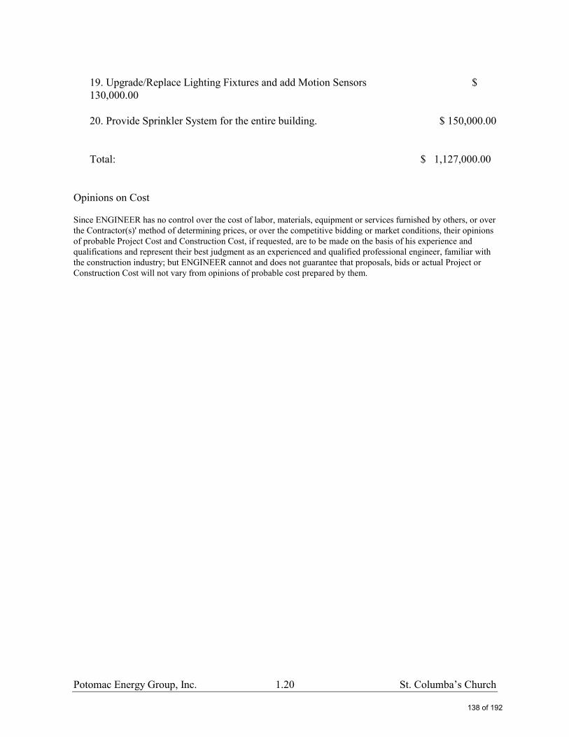
19. Upgrade/Replace Lighting Fixtures and add Motion Sensors $ 130,000.00 20. Provide Sprinkler System for the entire building. $ 150,000.00 Total: $ 1,127,000.00
Opinions on Cost Since ENGINEER has no control over the cost of labor, materials, equipment or services furnished by others, or over the Contractor(s)' method of determining prices, or over the competitive bidding or market conditions, their opinions of probable Project Cost and Construction Cost, if requested, are to be made on the basis of his experience and qualifications and represent their best judgment as an experienced and qualified professional engineer, familiar with the construction industry; but ENGINEER cannot and does not guarantee that proposals, bids or actual Project or Construction Cost will not vary from opinions of probable cost prepared by them.
138 of 192

Potomac Energy Group, Inc. 1.21
139 of 192

Potomac Energy Group, Inc. 1.22
PR OPOSE D SYST E MS D ESC RIPT I O NS The following HVAC systems are emerging as the most efficient systems for this facility. We have provided a short description of each system for your review.
1. & 5. A ir-cooled Chiller and Boiler with Fan Coil Units -
The system consists of individual floor mounted central air handlers with 2 or 4-pipe chilled and hot water coils to distribute the air in the areas, a air-cooled chiller located on the roof or on the ground if space is available, high efficiency condensing gas boilers located in the mechanical room, and hot and chilled water pumps to distribute the hot and chilled VFD water throughout the building.
Chilled water for cooling is supplied from the package air-cooled chiller and circulated to the fan coil or air handling units by circulating pumps.
In 2-pipe systems the heating and cooling cannot be achieved simultaneously.
2. Water Source H eat Pumps with Cooling Tower - This system consists of water source heat pump units with built-in compressor installed in mechanical rooms or inside the occupied rooms. The number of heat pump units will depend on zoning of the areas. Conditioned air is circulated through supply and return ducts. Each heat pump unit will have outside air duct connected to the unit.
Return air is normally through ceiling grilles with return ducts. The mechanical rooms have to be sound attenuated due to compressor noise radiated to the walls.
Condenser water for cooling is supplied from the cooling tower on the roof or on the ground if space is available and circulated to the heat pumps by circulating pumps. A heat exchanger is provided in the system to create a two-pipe closed loop circulating system.
Heat is added to the condenser water system for winter heating by high efficiency condensing gas boilers. PVC gas flues are extended through the roof or wall. The combustion air for the boilers is direct outside air intake.
The boilers, pumps, and heat exchanger can be located in the boiler room.
The system is capable of providing cooling or heating for the zone areas any time of the year
3. Multi-Split V R F Systems - Multi-splits pair a single outdoor condenser unit with multiple
indoor air handlers. With multi-splits, however, there can be as many as 40 indoor units for one outdoor unit. Multi-split systems also add a few features that extend the benefits of mini-splits to much larger settings.
Among these added features is variable refrigerant flow (VRF), also know as variable refrigerant volume (VRV). VRF systems allow different air handlers on a multi-split setup to offer a variety of comfort conditions, unlike many central systems, which offer a single for the whole system. VRF also allows delivery of various temperatures without cooling and the reheating air, a common and inefficient practice in large commercial buildings.
140 of 192

Potomac Energy Group, Inc. 1.23
Larger VRF multi split systems allow individual air handlers to heat or cool as needed, simultaneously. "When you're cooling in some units and heating in others, you're transferring heating from one spot to another," rather than generating it or exhausting it. Buildings with these systems also benefit when conditioning needs change with the time of day or in the spring and fall, when conditioning needs change rapidly.
4a. G eoexchange System- C losed Loop - A GeoExchange unit simply transfers energy (heat) from the ground or ground water into the space being conditioned during the winter months and transfers excess heat from the structure back into the ground or ground water in the summer months. Because the temperature of the ground or ground water remains fairly constant throughout the year.
In a closed loop system, the ground-coupled heat exchanger takes the form of sealed high density polyethylene piping buried vertically or horizontally in the ground. In the case of vertical systems, a series of 4-in. to 6-in. diameter bore holes are made (typically using water well drilling equipment to attain depths of 150 to 300 feet), a loop of piping is inserted into each hole, the various loops are tied together by a manifold and then the holes are grouted and backfilled. For horizontal systems, similar piping loops are buried in horizontal trenches dug 4 to 6 feet deep, the piping is connected by headers, and the trenches backfilled. In both vertical and horizontal closed-loop systems, the water or water/nontoxic antifreeze mixture in these pipes remains within the pipes for the life of the system.
4b. G eoexchange System (Open Loop)- Ground water is attractive as a heat exchange medium in residential and commercial space conditioning. By using a GeoExchange unit, ground water can serve as a heat source (for heating) and a heat sink (for cooling).
The temperature of the ground water is nearly the same year-round, regardless of the temperature extremes on the surface. Thus, it is warmer than the outside air in winter and cooler in summer. Since GeoExchange unit capacity and efficiency vary significantly with the heat source/sink temperature (or temperature difference between the source/sink and conditioned space), a GeoExchange systems offers considerable advantages over the more widely used air-to-air heat pump. Water will hold five times more heat than an equal weight of air and its heat content does not vary with its temperature. Air yields very little heat at temperatures below 25°F and will accept very little heat in the cooling cycle at temperatures above 85°F.
The ground-coupled heat exchanger can take a number of forms. In an open-loop systems, two wells are typically used. These are similar to conventional water wells, with one acting as a source well, and the other acting as a sink. Water is pumped from the source well, through a water-to-refrigerant heat exchanger on the GeoExchange system, and returned to the second well.
141 of 192

Potomac Energy Group, Inc. 1.24
142 of 192

Potomac Energy Group, Inc. 1.25
Steam Boiler (Over 50 years old)
Rooftop units serving auditorium (Over 20 years old)
143 of 192

Potomac Energy Group, Inc. 1.26
Air-cooled Chiller (Over 20 years old)
Typical Fan Coil Unit Piping Connection
Diesel Fueled Fire Pump
144 of 192

Potomac Energy Group, Inc. 1.27
Urinals with Inefficient Flush Valves
Fire Pump Test Header/FDC
Main electrical service equipment
145 of 192

Potomac Energy Group, Inc. 1.28
Overall Floor Plans
146 of 192
2425 South Yukon Ave - Tulsa, Oklahoma 74107-2728 - Ph. (918) 583-2266 Fax (918) 583-6094AAONEcat32 Ver. 4.179 (SN: 5593632-FQZKL37E)
1A 1B 1C 1D 2
3
4 5A 5B 5C 6A 6B 6C 7
8
9
10
11
12
13
14A
14B
15
16
17
18
19
20
21
22
23
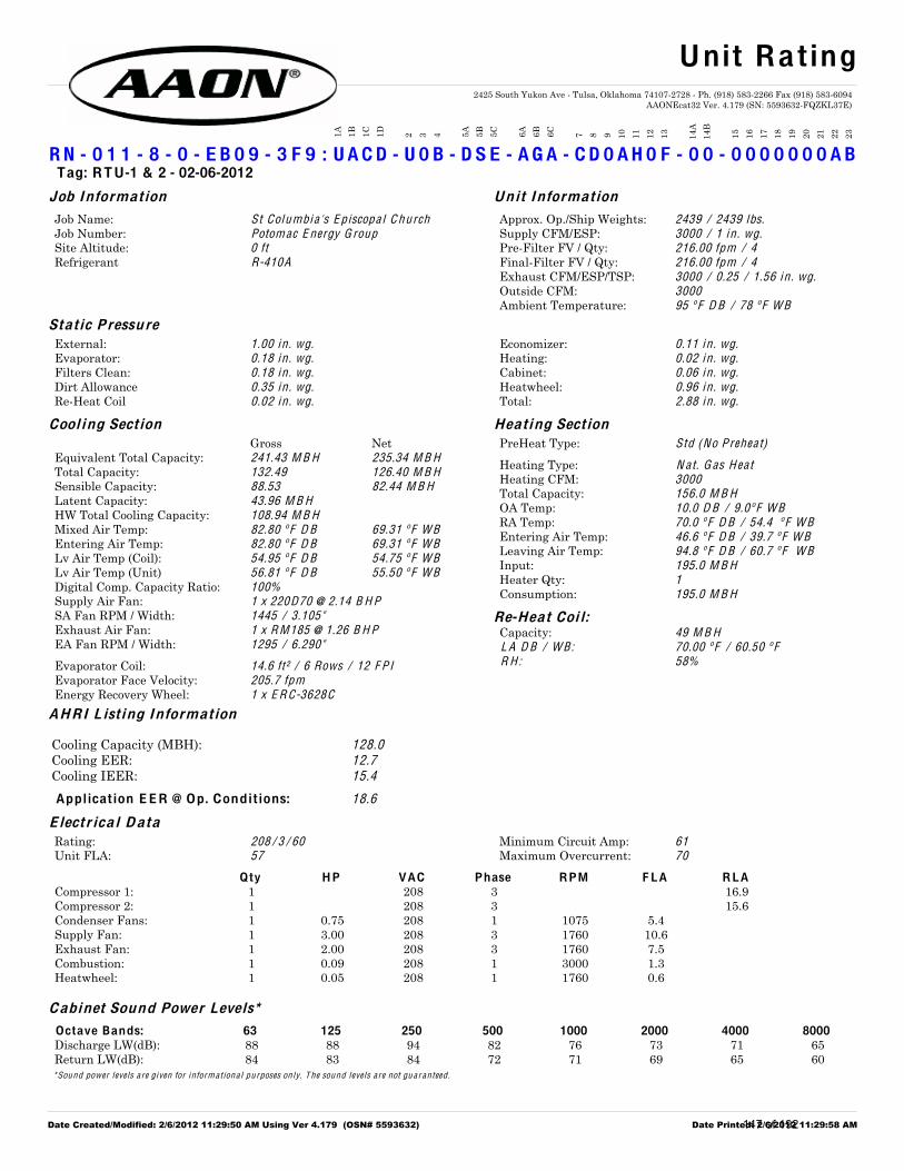
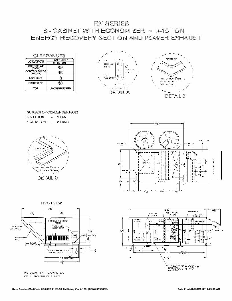
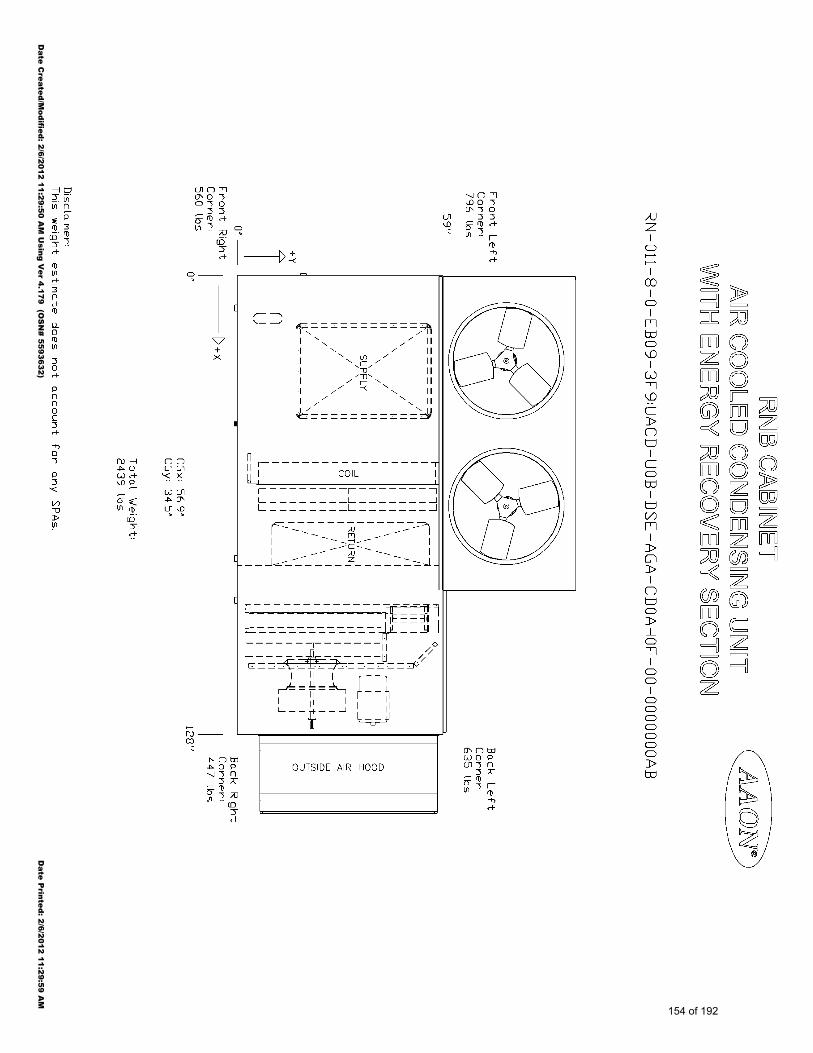
R N - 0 1 1 - 8 - 0 - E B 0 9 - 3 F 9 : U A C D - U 0 B - D S E - A G A - C D 0 A H 0 F - 0 0 - 0 0 0 0 0 0 0 A B Tag: RTU-1 & 2 - 02-06-2012
Job Information Unit Information
Job Name: Approx. Op./Ship Weights: Job Number: Supply CFM/ESP: Site Altitude: Pre-Filter FV / Qty: Refrigerant Final-Filter FV / Qty:
Exhaust CFM/ESP/TSP: Outside CFM: Ambient Temperature:
St Columbia's E piscopa l C hurch 2439 / 2439 lbs.Potomac E nergy G roup 3000 / 1 in . wg.0 ft 216.00 fpm / 4
R-410A 216.00 fpm / 4
3000 / 0.25 / 1.56 in . wg.3000
95 º F D B / 78 º F W B
Static P ressure External: Economizer: Evaporator: Heating: Filters Clean: Cabinet: Dirt Allowance Heatwheel: Re-Heat Coil Total:
1.00 in . wg. 0.11 in . wg.0.18 in . wg. 0.02 in . wg.0.18 in . wg. 0.06 in . wg.0.35 in . wg. 0.96 in . wg.0.02 in . wg. 2.88 in . wg.
Cool ing Sect ion Heating Sect ion
Gross Net Equivalent Total Capacity: Total Capacity: Sensible Capacity: Latent Capacity: HW Total Cooling Capacity: Mixed Air Temp: Entering Air Temp: Lv Air Temp (Coil): Lv Air Temp (Unit) Digital Comp. Capacity Ratio: Supply Air Fan: SA Fan RPM / Width: Exhaust Air Fan: EA Fan RPM / Width:
Evaporator Coil: Evaporator Face Velocity: Energy Recovery Wheel:
241.43 M B H 235.34 M B H
132.49 126.40 M B H
88.53 82.44 M B H
43.96 M B H
108.94 M B H
82.80 º F D B 69.31 º F W B
82.80 º F D B 69.31 º F W B
54.95 º F D B 54.75 º F W B
56.81 º F D B 55.50 º F W B
100%
1 x 220D70 @ 2.14 B H P
1445 / 3.105"
1 x R M185 @ 1.26 B H P
1295 / 6.290"
14.6 ft² / 6 Rows / 12 F P I
205.7 fpm
1 x E R C-3628C
PreHeat Type: Std (No Preheat)
Heating Type: Heating CFM: Total Capacity: OA Temp: RA Temp: Entering Air Temp: Leaving Air Temp: Input: Heater Qty: Consumption:
N at. G as H eat
3000
156.0 M B H
10.0 D B / 9.0º F W B
70.0 º F D B / 54.4 º F W B
46.6 º F D B / 39.7 º F W B
94.8 º F D B / 60.7 º F W B
195.0 M B H
1
195.0 M B H
Re-Heat Coi l: Capacity: 49 M B H
L A D B / W B: 70.00 º F / 60.50 º F
R H : 58%
AH RI L ist ing Information
Cooling Capacity (MBH): 128.0 Cooling EER: 12.7 Cooling IEER: 15.4
Application E E R @ Op. Conditions: 18.6
E lectr ica l D ata
Rating: Minimum Circuit Amp: Unit FLA: Maximum Overcurrent:
208 / 3 / 60 61
57 70
Qty H P VAC Phase RPM F LA R LA Compressor 1: 1 208 3 16.9 Compressor 2: 1 208 3 15.6 Condenser Fans: 1 0.75 208 1 1075 5.4 Supply Fan: 1 3.00 208 3 1760 10.6 Exhaust Fan: 1 2.00 208 3 1760 7.5 Combustion: 1 0.09 208 1 3000 1.3 Heatwheel: 1 0.05 208 1 1760 0.6
Cabinet Sound Power Levels* Octave Bands: 63 125 250 500 1000 2000 4000 8000 Discharge LW(dB): 88 88 94 82 76 73 71 65 Return LW(dB): 84 83 84 72 71 69 65 60 *Sound power leve ls a re given for informationa l purposes on ly. T he sound leve ls a re not gua ranteed .
Unit Rating
Date Created/Modified: 2/6/2012 11:29:50 AM Using Ver 4.179 (OSN# 5593632) Date Printed: 2/6/2012 11:29:58 AM147 of 192

2425 South Yukon Ave - Tulsa, Oklahoma 74107-2728 - Ph. (918) 583-2266 Fax (918) 583-6094AAONEcat32 Ver. 4.179 (SN: 5593632-FQZKL37E)
1A 1B 1C 1D 2
3
4 5A 5B 5C 6A 6B 6C 7
8
9
10
11
12
13
14A
14B
15
16
17
18
19
20
21
22
23
R N - 0 1 1 - 8 - 0 - E B 0 9 - 3 F 9 : U A C D - U 0 B - D S E - A G A - C D 0 A H 0 F - 0 0 - 0 0 0 0 0 0 0 A B Tag: RTU-1 & 2 - 02-06-2012
Job Name St Columbia's Episcop Heat Wheel Type: TotalJob Number Potomac Energy Group Heat Wheel Model: ERC-3628CSite Altitude 0' Heat Wheel Qty: 1
Summer Conditions Bypass: 0 CFM
Mixed Air Damper Supply Air HW Outside Air
3000 CFM 3000 CFM 3000 CFM82.80 ºF DB 82.80 ºF DB 82.80 ºF 95.00 ºF DB69.31 ºF WB 69.31 ºF WB 69.31 ºF 78.00 ºF WB86.17 gr/lb 86.17 gr/lb 118.01 gr/lbReturn Air From Space Exhaust Air
0 CFM 3000 CFM
75.00 ºF DB 87.20 ºF 87.20 ºF DB62.00 ºF WB 72.06 ºF 72.06 ºF WB62.44 gr/lb 94.28 gr/lb
3000 CFM Ex Bypass: 0 CFM
Cooling/Dehumidification Heating/Humidification
Total Capacity: 108.94 MBH 0.00 MBHSensible Capacity: 40.51 MBH 0.00 MBH
Latent Capacity: 68.43 MBH 0.00 MBH
Winter Conditions Bypass: 0 CFM
Mixed Air Damper Supply Air HW Outside Air
3000 CFM 3000 CFM 3000 CFM46.60 ºF DB 46.60 ºF DB 46.60 ºF 10.00 ºF DB39.65 ºF WB 39.65 ºF WB 39.65 ºF 9.00 ºF WB25.02 gr/lb 25.02 gr/lb 7.21 gr/lbReturn Air From Space Exhaust Air
0 CFM 3000 CFM
70.00 ºF DB 33.40 ºF 33.40 ºF DB54.40 ºF WB 30.60 ºF 30.60 ºF WB38.29 gr/lb 20.48 gr/lb
3000 CFM Ex Bypass: 0 CFM
Cooling/Dehumidification Heating/Humidification
Total Capacity: 0.00 MBH 154.77 MBHSensible Capacity: 0.00 MBH 118.84 MBH
Latent Capacity: 0.00 MBH 35.93 MBH
Energy Wheel Rating
Date Created/Modified: 2/6/2012 11:29:50 AM Using Ver 4.179 (OSN# 5593632) Date Printed: 2/6/2012 11:29:58 AM148 of 192

2425 South Yukon Ave - Tulsa, Oklahoma 74107-2728 - Ph. (918) 583-2266 Fax (918) 583-6094AAONEcat32 Ver. 4.179 (SN: 5593632-FQZKL37E)
JOB IN F ORMATION: WH E E L SP E CI F ICATION: Job Name: Max RPM: Job Tag: D iameter x Qty: Rep F i rm: Width%: Date: T ip Speed:
Inertia:
St Columbia's E piscopa l
C hurch
2,200
R T U-1 & 2 - 02-06-2012 22.0 in . x 1
90
02 / 06 / 2012 8,323 F P M
5 WR²
OP E RATING CON DITIONS: MOTOR SE L E CTION: Ai r F low: Rated H P / Bypass: Static P ressure: F rame Size: P lenum D P: Nominal RPM: Inlet G r i ll D P: VAC/P H /HZ: TSP: E fficiency Site Altitude: E nclosure Type: TSP @ Sea Level: Max Inertial Load:
3,000 C F M 3 / No
2.88 in . Wg. 182T
0.00 in . Wg. 1760
0.00 in . Wg. 208 / 3 / 60
2.88 in . Wg. Premium / 0.895
0.00 F t O D P
2.88 in . Wg. 29 WR²
F AN P E R F ORMANC E : F AN SOUN D POWE R (Inlet/Outlet): RPM: Octave Band: (Re 10^-12 watts) B H P: 1 2 3 4 5 6 7 8 E fficiency: In/Out Veloci ty: P lenum Out Veloci ty: SOUN D POWE R A-Weighted: 90 / 90 dB
1445
2.14
63.7% 88 87 94 83 79 76 74 68
917 / 1010 F P M 88 87 94 83 79 76 74 68
50 F P M
RPMBHPSYSTEMEfficiency
Supply Fan Model: 220D70 @ 1445 RPM and 90% WidthDesign Conditions: 3000 CFM @ 2.88" SP
CFM x 10004321
SP
3
2
1
0
BH
P
5
4
3
2
1
0
60%
40%
20%
0%
RPM: 1445
BHP: 2.14
EFFICIENCY: 63.65
22.0 " STAR Plenum
Date Created/Modified: 2/6/2012 11:29:50 AM Using Ver 4.179 (OSN# 5593632) Date Printed: 2/6/2012 11:29:59 AM149 of 192

2425 South Yukon Ave - Tulsa, Oklahoma 74107-2728 - Ph. (918) 583-2266 Fax (918) 583-6094AAONEcat32 Ver. 4.179 (SN: 5593632-FQZKL37E)
JOB IN F ORMATION: WH E E L SP E CI F ICATION: Job Name: Max RPM: Job Tag: D iameter x Qty: Rep F i rm: C F M: Date: T ip Speed:
Inertia:
St Columbia's E piscopa l
C hurch
2,200
R T U-1 & 2 - 02-06-2012 18.5 in . x 1
3000
02 / 06 / 2012 6,272 F P M
3 WR²
OP E RATING CON DITIONS: MOTOR SE L E CTION: Ai r F low: Rated H P / Bypass: Static P ressure: F rame Size: Relief Dampers D P: Nominal RPM:
VAC/P H /HZ: TSP: E fficiency Site Altitude: E nclosure Type: TSP @ Sea Level: Max Inertial Load:
3,000 C F M 2 / No
1.21 in . Wg. 145T
0.35 in . Wg. 1760
208 / 3 / 60
1.56 in . Wg. Standa rd / 0.785
0.00 F t O D P
1.56 in . Wg. 27 WR²
F AN P E R F ORMANC E : F AN SOUN D POWE R (Inlet/Outlet): RPM: Octave Band: (Re 10^-12 watts) B H P: 1 2 3 4 5 6 7 8 E fficiency: In/Out Veloci ty: P lenum Out Veloci ty: SOUN D POWE R A-Weighted: 83 / 83 dB
1295
1.26
58.5% 82 83 82 78 74 72 68 63
1523 / 1181 F P M 82 83 82 78 74 72 68 63
50 F P M
RPMBHPSYSTEMEfficiency
Exhaust Fan Model: RM185 @ 1295 RPM and 100% WidthDesign Conditions: 3000 CFM @ 1.56" SP
CFM x 10004321
SP
1
0
BH
P
2
1
0
40%
20%
0%
RPM: 1295
BHP: 1.26
EFFICIENCY: 58.53
18.5 " STAR Plenum
Date Created/Modified: 2/6/2012 11:29:50 AM Using Ver 4.179 (OSN# 5593632) Date Printed: 2/6/2012 11:29:59 AM150 of 192

2425 South Yukon Ave - Tulsa, Oklahoma 74107-2728 - Ph. (918) 583-2266 Fax (918) 583-6094AAONEcat32 Ver. 4.179 (SN: 5593632-FQZKL37E)
1A 1B 1C 1D 2
3
4 5A 5B 5C 6A 6B 6C 7
8
9
10
11
12
13
14A
14B
15
16
17
18
19
20
21
22
23
R N - 0 1 1 - 8 - 0 - E B 0 9 - 3 F 9 : U A C D - U 0 B - D S E - A G A - C D 0 A H 0 F - 0 0 - 0 0 0 0 0 0 0 A B Tag: RTU-1 & 2 - 02-06-2012
Job Name: St Columbia's E piscopa l C hurch Unit Submittal For: Job Number: Potomac E nergy G roup Unit Submittal Date: F ebrua ry 06, 2012
Base Option Descr iptionR Series Roof Top Unit
N Generation Ninth Generation
011 Unit Size Eleven
8 Voltage 208V/3Ø/60Hz
0 Interior Protection Standard
E Refrigerant Style R-410A VCC - High Efficiency
B Unit Configuration Air-Cooled Cond. + 6 Row Evap. Coil
0 Coil Coating Standard
9 Cooling/Heat Pump Staging Modulating - 1 VCC + 1 On/Off Comp.
3 Heating Type Natural Gas Stainless Steel
F Heating Designation Heat F - 195 MBtuh
9 Heating Staging Modulating Gas - Temperature Control
Feature Option Descr iptionU 1A. RA/OA Section AAONAIRE® Energy Recovery Wheel - Total + High CFM
A 1B. RA/EA Blower Configuration 1 Blower + Standard Efficiency Motor
C 1C. RA/EA Blower 18.5" Backward Curved Plenum
D 1D. RA/EA Blower Motor 2.0 hp - 1760 rpm
U 2. OA Control 2 Position Actuator
0 3. Heat Options Standard
B 4. Maintenance Options 115V Convenience Outlet - Factory Wired
D 5A. SA Blower Configuration 1 Blower + Premium Efficiency Motor + 1 VFD
S 5B. SA Blower 22'' Direct Drive Backward Curved Plenum - 70% Width
E 5C. SA Motor 3.0 hp - 1760 rpm
A 6A. Pre Filter Type 2" Pleated Pre Filter - 30% Eff
G 6B. Unit Filter Type 4" Pleated - 85% Eff - MERV 13
A 6C. Filter Options Clogged Filter Switch
C 7. Refrigeration Control Fan Cycling
D 8. Refrigeration Options Modulating Hot Gas Reheat
0 9. Refrigeration Accessories Standard
A 10. Power Options Power Switch - 100 amps
H 11. Safety Options Remote Safety Shutdown Terminals
0 12. Controls Standard
F 13. Special Controls Make Up Air Unit Controller - CV Cool + CV Heat
0 14A. Preheat Configuration Standard - None
0 14B. Preheat Sizing Standard - None
0 15. Glycol Percent Water or No WSHP
0 16. Interior Cabinet Options Standard - Double Wall + R-13 Foam Insulation + Stainless Steel Drain Pan
0 17. Exterior Cabinet Options Standard
0 18. Customer Code Standard
0 19. Code Options Standard - ETL U.S.A. Listing
0 20. Crating Standard
0 21. Water-Cooled Cond. Standard - None
A 22. Control Vendors Wattmaster Controls
B 23. Type Standard - Includes AAON Gray Paint
Unit Submittal
Date Created/Modified: 2/6/2012 11:29:50 AM Using Ver 4.179 (OSN# 5593632) Date Printed: 2/6/2012 11:29:59 AM151 of 192

2425 South Yukon Ave - Tulsa, Oklahoma 74107-2728 - Ph. (918) 583-2266 Fax (918) 583-6094AAONEcat32 Ver. 4.179 (SN: 5593632-FQZKL37E)
1A 1B 1C 1D 2
3
4 5A 5B 5C 6A 6B 6C 7
8
9
10
11
12
13
14A
14B
15
16
17
18
19
20
21
22
23
R N - 0 1 1 - 8 - 0 - E B 0 9 - 3 F 9 : U A C D - U 0 B - D S E - A G A - C D 0 A H 0 F - 0 0 - 0 0 0 0 0 0 0 A B Tag: RTU-1 & 2 - 02-06-2012 Job Name: St Columbia's Episcopa l
ChurchVCMX For:
Job Number: Potomac Energy Group VCMX Date: Februa ry 06, 2012
Hardware Included For VCMX Controller
Part # Included Parts Assigned ChannelV07150 VCMX Controller with EBUSR28390 Suction Pressure Transducer MainController\AI5R82890 Supply Air Temp Sensor - Field Installed MainController\AI2R81550 Outside Air Temp Sensor MainController\AI4R69190 VCMX Large Expansion ModuleP62520 Proof of Flow Sensor LargeExpansionModule\BI3P62520 Dirty Filter Sensor LargeExpansionModule\BI2R34700 Outside Air Humidity Sensor LargeExpansionModule\AI1
1 2 3 4 5 6 7
VCMXControllerwith E BUS
Analog In X X XAnalog Out X XBinary InRelay Out X X X X XDigital Sensor(s)
1 2 3 4 5 6 7 8VCMXLarge
ExpansionModule
Analog In XAnalog Out XBinary In X X XRelay Out
VCMX Components
Date Created/Modified: 2/6/2012 11:29:50 AM Using Ver 4.179 (OSN# 5593632) Date Printed: 2/6/2012 11:29:59 AM152 of 192
Date Created/Modified: 2/6/2012 11:29:50 AM Using Ver 4.179 (OSN# 5593632) Date Printed: 2/6/2012 11:29:59 AM153 of 192
Date C
reated/Modified: 2/6/2012 11:29:50 A
M U
sing Ver 4.179 (O
SN
# 5593632) D
ate Printed: 2/6/2012 11:29:59 A
M
154 of 192

Submittal Data SheetSt Columba's Episcopal ChurchProject Name:
Location: Joshua WarfieldEngineer:
Potomac Energy GroupSubmitted to: Submitted by:
HavtechReference:
Approval: 2/2/2012Date:
Construction: Unit #: Drawing #:
PerformanceDuctedIndoor Unit Model No:
RWEYQ144PTJUOutdoor Unit Model No: 144000Rated Cooling Capacity (Btu/hr):
0Sensible Capacity (Btu/hr): Cooling Input Power (kW):
15.3Cooling EER (Btu/hr / kW): N/ASEER:
162000Rated Heating Capacity (Btu/hr): Heating Input Power (kW):
5.3Heating COP (Btu/hr / Btu/hr): N/AHSPF:
Indoor Unit Type: 12-Ton VRV-WIII Heat PumpCondensing Unit Type:
Indoor: 80°F DB/67°F WBCooling Nominal Outdoor: 95°F DB/75°F WBConditions Water Cooled: 85Indoor: 70°F DB/60°F WBHeating Nominal Outdoor: 47°F DB/43°F WBConditions Water Cooled: 70
25Nominal Piping Length 0Nominal Height Separation
25.4 GPMNominal Water Flow Rate
Indoor Unit DetailsN/APower Supply (V/Hz/Ph:)
Power Supply Connections: Min. Circuit Amps MCA (A): Max. Fusible Amps MFA (A):
N/ADimensions (HxWxD): N/APanel (HxWxD):
Net Weight (lbs): Weight with Panel (lbs):
N/AAirflow Rate (CFM wet coil) Moisture Removal (pt/h): Gas Pipe Connection (inch): Liquid Pipe Connection (inch): Condensate Connection (inch): Sound Pressure Level (dBA): Sound Power Level (dBA): Nominal External Static Pressure (inH2O) Max Ext Static Pressure (inH2O)
Condensing Unit Details208-230/60/3phPower Supply (V/Hz/Ph):
L1, L2, L3 GroundPower Supply Connections: 22.4+22.4Min. Circuit Amps MCA (A):
40 + 40Max. Fusible Amps MFA (A): -Max. Starting Current MSC(A):
11.6+11.6Rated Load Amps RLA (A): 24 + 24Total Overcurrent Amps (A):
39-3/8x62-1/4x21-11/16Dimensions (HxWxD): 330 x 2Net Weight (lbs): InverterCompressor Type:
11 - 100Capacity Control Range (%): 72 - 187 (130%)Capacity Index Limit:
N/AAirflow Rate (CFM): 1-1/8Gas Pipe Connection (inch):
1/2Liquid Pipe Connection (inch): H/L Pressure Connection (inch): H/L Equalizing Connection (inch):
1-1/4FPTWater Inlet Connection (inch FPT): 1-1/4FPTWater Outlet Connection (inch FPT):
1/2FPSCondensate Drain Outlet (inch FPS): 53Sound Pressure Level (dBA):
Sound Power Level (dBA): 0.64 + 0.64Unit Heat Rejection (kW):
20Max. No. of Indoor Units:
System DetailsR-410ARefrigerant Type: 9.9+9.9Holding Refrigerant Charge (lbs):
install dataAdditional Charge (oz/ft): -Pre-charge Piping (Length ft):
390 ftMax. Pipe Length (Total ft): 164 ft / 130 ftMax. Pipe Length (Vertical ft):
35 - 104 (Mech. Room)Cooling Operation Range (°F): Cooling Range w/Baffle (°F):
35 - 104 (Mech. Room)Heating Operation Range (°F): Heating Range w/Baffle (°F):
(43) 59 - 113Cooling Inlet Water Temp (°F): (14) 50 - 113Heating Inlet Water Temp (°F):
13.2 - 39.5Water Flow Range (GPM):
Page 1 of 7Daikin AC (Americas), Inc., 1645 Wallace Drive - Suite 110, Carrollton, TX 75006Daikin AC TRL Generated Submittal Data www.daikinac.com
(Daikin's products are subject to continuous improvements. Daikin reserves the right to modify product design, specifications and information in this data sheet without notice and without incurring any obligations)155 of 192

Submittal Data SheetSt Columba's Episcopal ChurchProject Name:
Location: Joshua WarfieldEngineer:
Potomac Energy GroupSubmitted to: Submitted by:
HavtechReference:
Approval: 2/2/2012Date:
Construction: Unit #: Drawing #:
156 of 192

Submittal Data SheetSt Columba's Episcopal ChurchProject Name:
Location: Joshua WarfieldEngineer:
Potomac Energy GroupSubmitted to: Submitted by:
HavtechReference:
Approval: 2/2/2012Date:
Construction: Unit #: Drawing #:
Dimensional Drawing - Condensing Unit
Page 3 of 7Daikin AC (Americas), Inc., 1645 Wallace Drive - Suite 110, Carrollton, TX 75006Daikin AC TRL Generated Submittal Data www.daikinac.com
(Daikin's products are subject to continuous improvements. Daikin reserves the right to modify product design, specifications and information in this data sheet without notice and without incurring any obligations)157 of 192
Submittal Data SheetSt Columba's Episcopal ChurchProject Name:
Location: Joshua WarfieldEngineer:
Potomac Energy GroupSubmitted to: Submitted by:
HavtechReference:
Approval: 2/2/2012Date:
Construction: Unit #: Drawing #:
Notes
Requires Multi Connection Pipe Kit (BHFP22MA56U), Std U.S. Warranty: 6yrs Compressor, 1yrs Parts, 1yr Limited Labor
Page 4 of 7Daikin AC (Americas), Inc., 1645 Wallace Drive - Suite 110, Carrollton, TX 75006Daikin AC TRL Generated Submittal Data www.daikinac.com
(Daikin's products are subject to continuous improvements. Daikin reserves the right to modify product design, specifications and information in this data sheet without notice and without incurring any obligations)158 of 192
Submittal Data SheetSt Columba's Episcopal ChurchProject Name:
Location: Joshua WarfieldEngineer:
Potomac Energy GroupSubmitted to: Submitted by:
HavtechReference:
Approval: 2/2/2012Date:
Construction: Unit #: Drawing #:
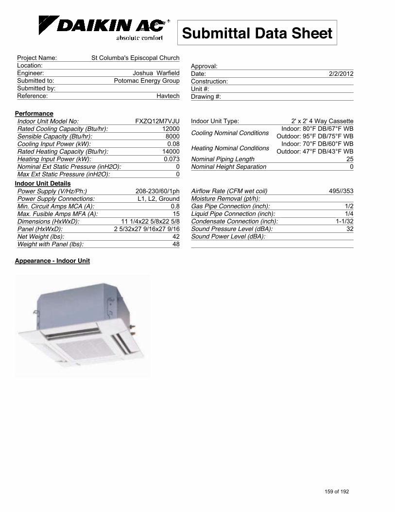
PerformanceFXZQ12M7VJUIndoor Unit Model No:
12000Rated Cooling Capacity (Btu/hr): 8000Sensible Capacity (Btu/hr): 0.08Cooling Input Power (kW):
14000Rated Heating Capacity (Btu/hr): 0.073Heating Input Power (kW):
0Nominal Ext Static Pressure (inH2O): 0Max Ext Static Pressure (inH2O):
2' x 2' 4 Way CassetteIndoor Unit Type: Indoor: 80°F DB/67°F WBCooling Nominal Conditions Outdoor: 95°F DB/75°F WBIndoor: 70°F DB/60°F WBHeating Nominal Conditions Outdoor: 47°F DB/43°F WB
25Nominal Piping Length 0Nominal Height Separation
Indoor Unit Details208-230/60/1phPower Supply (V/Hz/Ph:) L1, L2, GroundPower Supply Connections:
0.8Min. Circuit Amps MCA (A): 15Max. Fusible Amps MFA (A):
11 1/4x22 5/8x22 5/8Dimensions (HxWxD): 2 5/32x27 9/16x27 9/16Panel (HxWxD):
42Net Weight (lbs): 48Weight with Panel (lbs):
495//353Airflow Rate (CFM wet coil) Moisture Removal (pt/h):
1/2Gas Pipe Connection (inch): 1/4Liquid Pipe Connection (inch):
1-1/32Condensate Connection (inch): 32Sound Pressure Level (dBA):
Sound Power Level (dBA):
Appearance - Indoor Unit
159 of 192

Submittal Data SheetSt Columba's Episcopal ChurchProject Name:
Location: Joshua WarfieldEngineer:
Potomac Energy GroupSubmitted to: Submitted by:
HavtechReference:
Approval: 2/2/2012Date:
Construction: Unit #: Drawing #:
Dimensional Drawing - Indoor Unit
Page 6 of 7Daikin AC (Americas), Inc., 1645 Wallace Drive - Suite 110, Carrollton, TX 75006Daikin AC TRL Generated Submittal Data www.daikinac.com
(Daikin's products are subject to continuous improvements. Daikin reserves the right to modify product design, specifications and information in this data sheet without notice and without incurring any obligations)160 of 192

Submittal Data SheetSt Columba's Episcopal ChurchProject Name:
Location: Joshua WarfieldEngineer:
Potomac Energy GroupSubmitted to: Submitted by:
HavtechReference:
Approval: 2/2/2012Date:
Construction: Unit #: Drawing #:
Notes
Std U.S. Warranty: 6yrs Compressor, 1yrs Parts, 1yr Limited Labor
Page 7 of 7Daikin AC (Americas), Inc., 1645 Wallace Drive - Suite 110, Carrollton, TX 75006Daikin AC TRL Generated Submittal Data www.daikinac.com
(Daikin's products are subject to continuous improvements. Daikin reserves the right to modify product design, specifications and information in this data sheet without notice and without incurring any obligations)161 of 192

4733 Bethesda Avenue 301.652.8550 (Tel) Suite 550 301.652.1999 (fax) Bethesda, Maryland 20814 www.shinberglevinas.com
Appendix B XI.
Wiss, Janney, Elstner Associates, Inc. (WJE)- Report dated August 19, 2010
162 of 192

ST. COLUMBA'S CHURCH NURSERY SCHOOL Evaluation of Uncontrolled Rainwater Penetration 4201 Albemarle Street, Washington, DC 20016
Final Report
August 19, 2010 WJE No. 2010.3091
Prepared for: Lisa Sleith Project Manager E & G Group 1350 Beverly Road, Suite 200 McLean, Virginia 22101
Prepared by: Wiss, Janney, Elstner Associates, Inc. 2751 Prosperity Avenue, Suite 450 Fairfax, Virginia 22031 703.641.4601 tel | 703.641.8822 fax
163 of 192
ST. COLUMBA'S CHURCH NURSERY SCHOOL Evaluation of Uncontrolled Rainwater Penetration 4201 Albemarle Street, Washington, DC 20016
Sonja G. Hinish, EIT Associate II
Kenneth A. Kosteva, PE Senior Associate
Matthew C. Farmer, PE Principal and Project Manager
Final Report
August 19, 2010 WJE No. 2010.3091
Prepared for: Lisa Sleith Project Manager E & G Group 1350 Beverly Road, Suite 200 McLean, Virginia 22101
Prepared by: Wiss, Janney, Elstner Associates, Inc. 2751 Prosperity Avenue, Suite 450 Fairfax, Virginia 22031 703.641.4601 tel | 703.641.8822 fax
164 of 192

TABLE OF CONTENTS Introduction ................................................................................................................................................... 1construction ................................................................................................................................................... 1Observations ................................................................................................................................................. 2
Clay Masonry Façade ............................................................................................................................. 2Exterior ............................................................................................................................................ 2Interior ............................................................................................................................................. 2
Inspection pits ............................................................................................................................................... 3Inspection Pit No. 1 ................................................................................................................................ 3Inspection Pit No. 2 ................................................................................................................................ 3
Field Water Penetration Testing ................................................................................................................... 3Field Testing Methodology .................................................................................................................... 3Uncontrolled Water Penetration Field Test Results - 26 July 2010 ....................................................... 4
Test No. 1: Masonry Façade at Grade.............................................................................................. 4Test No. 2: Masonry Façade at Stair ................................................................................................ 4Test No. 3: Vertical Joint between Masonry Façade and 2nd Floor Patio Wall .............................. 5Test No. 4: Masonry Façade at 2nd Floor Stair Landing ................................................................. 5Test No. 5: Horizontal Joint in 3rd Floor Balcony Slab .................................................................. 5
Uncontrolled Water Penetration Field Test Results - 4 August 2010 .................................................... 5Test Location No. 6: Masonry Façade below Setback ..................................................................... 6Test Location No. 7: Masonry Façade Directly above Setback ....................................................... 6Test Location No. 8: Masonry Façade 5’ above Setback................................................................. 6
Discussion ..................................................................................................................................................... 6As-Built Conditions ................................................................................................................................ 6Source of Uncontrolled Water Penetration ............................................................................................. 7
Recommendations ......................................................................................................................................... 9
165 of 192
ST. COLUMBA'S CHURCH NURSERY SCHOOL Evaluation of Uncontrolled Rainwater Penetration 4201 Albemarle Street, Washington, DC 20016 INTRODUCTION At the request of Ms. Lisa Sleith of the E&G Group (E&G), Wiss, Janney, Elstner Associates (WJE) has
completed an evaluation of uncontrolled rainwater penetration at St. Columba’s Church Nursery School.
We understand that uncontrolled water penetration is commonly observed in the restrooms at the east end
of the north wall of the nursery school, at the lowest level. The water is typically observed on the floor
and portions of the north wall following rain events. The areas where water is generally observed
correlate with the below-grade portion of the north wall. E&G has requested that WJE assist with
determining the source of the uncontrolled rainwater penetration and develop conceptual
recommendations for remediation.
CONSTRUCTION Originally constructed in 1926, St. Columba’s Church is located at 4201 Albemarle Street, Washington,
DC. At the rear of St. Columba’s Church is a multi-wing addition. The Albemarle Street wing of the
present parish hall was completed in 1959. The Albemarle Street parish hall wing was renovated in 1989
and the Butterworth Street wing and Common were added. The lowest level of the Butterworth Street or
north wing contains classrooms and restrooms that are part of a nursery school. The exterior walls of the
addition are comprised of an outer clay masonry brick veneer with a concrete masonry unit (CMU) back-
up wall. The north wall of the north wing of the addition is bounded by a parking lot and is partially
below grade.
The masonry façade is comprised of an outer clay masonry brick veneer of standard size units and a CMU
back-up wall. Punched window openings are located at regular intervals at the first, second, and third
floors. A rowlock masonry sill is present below each window opening. “Accent bands” are created at the
first floor with recurring strips of split-face brick; similar split-face units are installed in a soldier course
above each window opening. A brick corbel with inset architectural precast concrete “keystones” is
present at the sill of the second floor windows.
166 of 192
St. Columba's Church Nursery School Evaluation of Uncontrolled Water Penetration
August 19, 2010 Page 2
A stair is located at the easternmost end of the north elevation of the addition. The stair provides access
to the second and third floors. The stair is comprised of a structural steel frame and precast concrete
planks. A topping slab is placed on the planks at the third floor stair landing.
OBSERVATIONS Mr. Kenneth Kosteva and Ms. Sonja Hinish, both of WJE, were on-site at the St. Columba’s Church
Nursery School on July 26 and August 4, 2010. WJE performed a limited visual condition survey of the
above grade exterior walls and interior walls. The following exterior and interior observations were
documented:
Clay Masonry Façade Exterior
Given the age and exposure of the building, the façade appears to be in generally fair condition.
Bond-line failures, excessive spalling, or other evidence of distress were generally not observed in the
areas tested.
Evidence of prior masonry removal and replacement is apparent near the expansion in the façade.
Through-wall flashing is visible near grade and above the corbel at the second floor (Figure 1). The
flashing appears to be a PVC material and does not appear to be fully adhered or bedded. The
flashing is above-grade at most locations; however, the easternmost portion (approximately twenty
feet) is below grade.
The topping slab at the third floor is in poor condition; numerous spalls and cracks are present
throughout the slab. The structural steel that supports the third floor landing is corroded at many
locations.
The visible slab at the second floor landing is in fair condition and does not contain spalls or cracks.
Interior
The interior floors are covered with vinyl composite floor tiles (Figure 2). The concrete floor slabs
appear to extend to the inside face of the CMU wythe of the exterior walls.
167 of 192

St. Columba's Church Nursery School Evaluation of Uncontrolled Water Penetration
August 19, 2010 Page 3
The interior face of the CMU wythe of the exterior wall is exposed and painted at the interior (Figure
3).
There is a gap approximately 2 inch wide that is filled with rigid insulation between the concealed
face of the brick masonry façade and the CMU backup wall as seen through a vent duct penetration
(Figure 4).
INSPECTION PITS WJE made two approximately 10” deep inspection pits in the soil immediately adjacent to the north face
of the masonry façade to assess below-grade conditions and determine if the through-wall flashing visible
above grade is present at areas of the façade that are below grade.
Inspection Pit No. 1 The first inspection pit was created approximately twelve inches to the east of the easternmost window on
the north elevation (Figure 5). PVC through-wall flashing was observed at the expansion joint; the
flashing is two brick courses below grade at this location (Figure 6). Below grade waterproofing was not
observed on the exterior of the brick veneer.
Inspection Pit No. 2 The second inspection pit was created approximately twelve inches to the west of the westernmost
window on the north elevation (Figure 7). At this location the PVC through-wall flashing was visible
above grade. Filter fabric and gravel fill that comprise a “french drain” were exposed at the second
inspection pit (Figure 8). At the location surveyed, the gravel within the filter fabric contained numerous
voids and appeared able to accommodate water flow. The “french drain” was not visible at grade, and it
is not known if the “french drain” is tied into other below grade drain lines.
FIELD WATER PENETRATION TESTING Field Testing Methodology While on-site on July 26 and August 4 2010, WJE conducted water penetration testing at selected
locations along the north elevation of the building in an effort to determine the source(s) of water damage
to the interior (see Figures 9 and 10). A combination of field testing methods was employed to determine
the points of entry and leak paths for water penetration. Typically, water was applied at each test location
168 of 192

St. Columba's Church Nursery School Evaluation of Uncontrolled Water Penetration
August 19, 2010 Page 4
utilizing the water spray delivery system or “spray rack” described in ASTM E 1105 Standard Test
Method for Field Determination of Water Penetration of Installed Exterior Windows, Skylights, Doors,
and Curtain Walls, by Uniform or Cyclic Static Air Pressure Difference. All testing was completed at a
static uniform pressure differential of 0.0 psf. Testing at grade was completed with the air of a soaker
hose. Water was delivered through small openings along the entire length of the hose at low pressure.
Limited testing was completed with the calibrated spray nozzle assembly as described in AAMA 501.2
Quality Assurance and Diagnostic Water Leakage Field check of Installed Storefronts, Curtain Walls,
and Sloped Glazing Systems. Utilizing a hand-held spray nozzle with a central valve and pressure gage,
selected joints and wall components were systematically sprayed in accordance with the application
methods outlined in the test standard.
Typically, field testing of exterior wall surfaces was systematically completed beginning at the lowest
exterior construction joint or interface condition directly opposite each identified “leak area”, working
upward until the point(s) of entry and leak path(s) recreated during each test were determined by WJE to
be consistent in location, rate and volume to actual rainwater penetration observed at the property.
Exterior wall conditions adjacent to each test area were isolated as required at the discretion of WJE
during each field test to minimize the potentially negative impact of “overspray” on our field test results.
During field testing, the interior of each test area was continuously monitored for any evidence of
uncontrolled water penetration. The following is a summary of field test results for each area included in
our testing program.
Uncontrolled Water Penetration Field Test Results - 26 July 2010 The majority of the testing completed by WJE was conducted on 26 July 2010. Test No. 1: Masonry Façade at Grade
A soaker hose was placed directly adjacent to the façade at grade from the bottom of the stair to the start
of the third window to the east of the stair (Figure 11). Water was applied at this location for
approximately two hours with no observed signs of water penetration at the interior of the building.
Test No. 2: Masonry Façade at Stair
Water was applied to the sloped fill between the stair and the masonry façade at the first floor level (see
Figure 12). Water was applied at the top of the sloped grade and was allowed to flow freely from the top
169 of 192
St. Columba's Church Nursery School Evaluation of Uncontrolled Water Penetration
August 19, 2010 Page 5
of the slope to the bottom. Water was applied at this location for approximately one hour with no
observed signs of water penetration at the interior of the building.
Test No. 3: Vertical Joint between Masonry Façade and 2nd Floor Patio Wall
Water was then applied to the open (unsealed) vertical joint between the masonry façade and the second
floor stair landing wall (Figure 13). A calibrated spray nozzle was used to direct water into the open
joint. Water was applied to the joint for approximately one hour with no observed signs of water
penetration at the interior of the building.
Test No. 4: Masonry Façade at 2nd Floor Stair Landing
Water was then applied to the masonry façade at the second floor stair landing and the horizontal joint
between the masonry façade and the landing (Figure 14). A calibrated spray rack was used to apply water
to the facade. The spray rack was positioned approximately 6 inches above the stair landing. Water was
applied at this location for approximately one hour with no observed signs of water penetration at the
interior of the building.
Test No. 5: Horizontal Joint in 3rd Floor Balcony Slab
Water was applied to a horizontal joint at the south limit of the third floor stair landing (Figure 15). A
spray rack was positioned approximately 6 inches from the horizontal joint and water was allowed to
sheet over the joint. Approximately 10 minutes into testing, water was observed on the interior at the
entryway and kitchen on the second floor and in both restrooms on the first floor (Figures 16 and 17).
Testing was stopped after 20 minutes due to the volume of water entering interior spaces. Water was
observed on the interior face of the CMU wythe and dripping from conduits and the underside of the slab
within the plenum space at the second floor. Water dripping from the underside of the slab and the
conduits wetted ceiling tiles and light fixtures at the second floor. Similar water penetration was observed
at the first floor. Water on the interior face of the CMU wythe ultimately pooled on the floor slab
adjacent to the wall.
Uncontrolled Water Penetration Field Test Results - 4 August 2010
WJE completed additional testing on 4 August 2010. The focus of the additional testing was the portion
of the façade above the area where damage was most evident in both interior restrooms (Figure 18).
170 of 192

St. Columba's Church Nursery School Evaluation of Uncontrolled Water Penetration
August 19, 2010 Page 6
Test Location No. 6: Masonry Façade below Setback
Water was applied via a spray rack to the north elevation immediately west of the stair, approximately 2’-
6” below the corbel in the masonry façade (Figure 19). Water was applied to this location for
approximately 2 hours with no observed signs of water penetration at the interior.
Test Location No. 7: Masonry Façade Directly above Setback
Water was then applied via a spray rack to the north elevation immediately west of the stair,
approximately 6 inches above the corbel in the masonry façade (Figure 20). Water was applied at this
location for approximately 1 hour with no observed signs of water penetration at the interior.
Test Location No. 8: Masonry Façade 5’ above Setback
Water was then applied via spray rack to the north elevation immediately west of the stair, approximately
5 feet below the third floor stair landing (Figure 21). Water was applied at this location for approximately
1 hour with no observed signs of water penetration at the interior.
DISCUSSION The following discussion contains a summary of the exterior wall construction and the intended
performance water management system, as well as, the leak path(s) identified during field testing.
As-Built Conditions WJE was not provided with original drawings to illustrate the construction of the exterior walls at the
areas tested, and inspection openings to verify the wall construction were not created. During the course
of our investigation, an unrelated opening was created in the façade to facilitate the installation of a duct
penetration through the wall in question. WJE was able to make limited inspections at the opening, which
illustrated that the wall assembly is comprised of an exterior clay masonry wythe, rigid insulation, and an
interior CMU wythe.
In masonry wall construction, water and moisture laden air are typically managed by utilizing a “cavity,”
“mass,” or a “barrier” style wall construction: In cavity wall construction, bulk rainwater is expected, by
design, to migrate through the outer brick wythe into a concealed wall cavity, where it then is allowed to
migrate down the interior surface of the outer brick wythe to a continuous line of through-wall flashing
and weeps at all interruptions in the cavity (including window penetrations and possibly slab edge
locations). In mass wall construction, bulk rainwater penetration resistance relies primarily upon the
171 of 192

St. Columba's Church Nursery School Evaluation of Uncontrolled Water Penetration
August 19, 2010 Page 7
nominal thickness and storage capacity for moisture of the masonry itself to resist water penetration. In
barrier wall construction, weather-resistance relies principally upon the surface integrity of the outermost
surface of the masonry prior to absorption into the masonry and the storage capacity of the masonry itself
(and, in certain instances, a fully grouted collar joint).
Based on our observations and field testing results the masonry wall assemblies tested at St. Columba’s
appear to be designed and constructed as cavity wall assemblies. Through-wall flashing lines and weeps
are present at grade and at the corbel at the second floor and the presence of the insulation in the wall
assembly ensure that a cavity exists between the concealed face of the outer clay masonry wythe and the
inner CMU wythe. While inspection openings to verify the construction and integrity of the through-wall
flashing at these locations were not made, the results of our testing suggest that the flashing is capable of
diverting water within the wall cavity to the exterior. The below-grade “french drain” located directly
adjacent to the north elevation appears to be comprised of large poorly graded stone wrapped in filter
fabric. The results of our testing indicated that the “french drain” effectively drains water away from
below grade portions of the wall.
The third floor stair landing is comprised of precast concrete planks and a cast-in-place concrete topping
slab. While the underside of the second floor landing is not visible, it is likely that similar planks
comprise this landing as well. The precast concrete planks span from north to south and are supported by
structural steel beams on the north edge of the landing. The south portion of the landing appears to bear
on the CMU inner wythe. The construction at this location places the construction joint at the south edge
of the landing inboard of the water management system. The joint is located approximately 18 inches
inboard of the face of the wall assembly, which is approximately 12 inches thick. The topping slab
installed at the third floor landing is in poor condition; numerous spalls and incipient spalls are present
throughout the slab.
Source of Uncontrolled Water Penetration
Based on the results of our observations and field testing, the primary source of water penetration is the
inadequately sealed construction joint at the south limit of the third floor landing of the stair. Water
introduced at this location quickly produced water penetration at the second floor and subsequently at the
first floor. The results of our testing indicate that the joint is not effectively sealed; at the surface, the
joint is open and water is able to freely enter the joint. While it is unknown if a waterproofing layer is
172 of 192

St. Columba's Church Nursery School Evaluation of Uncontrolled Water Penetration
August 19, 2010 Page 8
present below the visible topping slab (i.e. at the elevation of the precast concrete planks), the results of
our testing illustrate that any means of controlling water below the elevation of the topping slab are
ineffective. In addition to the lack of an effective seal at the joint, the observed water penetration also
results from the location of the joint relative to the wall below. The joint is located inboard of the wall
below and the precast concrete planks appear to bear on the wall. As a result, water within the joint is
able to enter the exterior wall assembly inboard of the water management system (i.e. the through-wall
flashing), which is likely located on the outboard face of the CMU wythe.
Water penetration was initially noted on the interior face of the CMU wythe immediately adjacent to the
underside of the third floor slab. The water observed at this location rapidly began to run vertically down
the face of the wall and tracked horizontally on the underside of the slab. The water tracking on the
underside of the slab dripped onto the interior finishes, including the door to the second floor landing, the
florescent light fixtures adjacent to the door, and various ceiling tiles. Each of the aforementioned interior
finishes exhibited evidence of previous ling-term water penetration in the form of staining. In general, the
water observed at the second floor appeared to reproduce water penetration occurring previously as a
result of natural rain events.
The water penetration observed at the first floor was similar to that observed at the second floor. Water
was observed dripping from the underside of the second floor slab and running down the interior face of
the CMU wythe. We understand that water is sometimes present on the floor of the restrooms at the first
floor following significant rain events; however, the initial entry point was not indicated to WJE.
The water penetration observed during testing appeared to recreate several previously experienced leaks
at the first and second floors; however, the damage (peeling paint) on the interior face of the CMU wythe
in the restrooms was not replicated. The rationale for the failure to replicate the previously observed
wetting of the CMU at this location may be the relatively aggressive nature of the water application
during testing. The aforementioned joint at the south limit of the third floor stair landing is partially
sheltered from rainwater by the roof above; therefore, the joint is likely wetted in a more moderate
fashion during rain events. During testing, a large volume of water was applied to the joint in a short
period of time, which, may explain why the water penetration observed at the interior was more
prominent than that observed during most rain events.
173 of 192
St. Columba's Church Nursery School Evaluation of Uncontrolled Water Penetration
August 19, 2010 Page 9
Water applied at grade and to the façade below the third floor stair landing was effectively managed by
the wall assembly, as no water penetration was observed at the interior. While the flashing at grade
passes below-grade at the east portion of the wall, an additional line of through-wall flashing is present
approximately ten courses above the below-grade flashing. This flashing was presumably installed to
limit the amount of water that must be managed by the below-grade flashing. In general, water applied to
the façade directly adjacent to the area where damage is apparent at the interior, appeared to be effectively
managed by the wall assembly.
RECOMMENDATIONS Based on the results of our testing, we recommend that an effective means of managing water be
established at the third floor landing of the stair. Two repair options should be considered; the
appropriate repair option should be selected based on the existing conditions below the topping slab. If an
existing waterproofing layer is present below the topping slab, the waterproofing should be repaired, as
necessary, and measures should be employed to establish an effective transition or termination at the
south edge of the landing. If a waterproofing layer is not present below the topping slab, the topping slab
should be repaired and a pedestrian grade urethane waterproofing system should be applied to the stair
landing, including the area to the south of the landing. Care should be taken to ensure that the joint at the
south edge of the stair is treated in accordance with the manufacturers recommendations prior to
application of the waterproofing membrane.
174 of 192

FIGURES
175 of 192
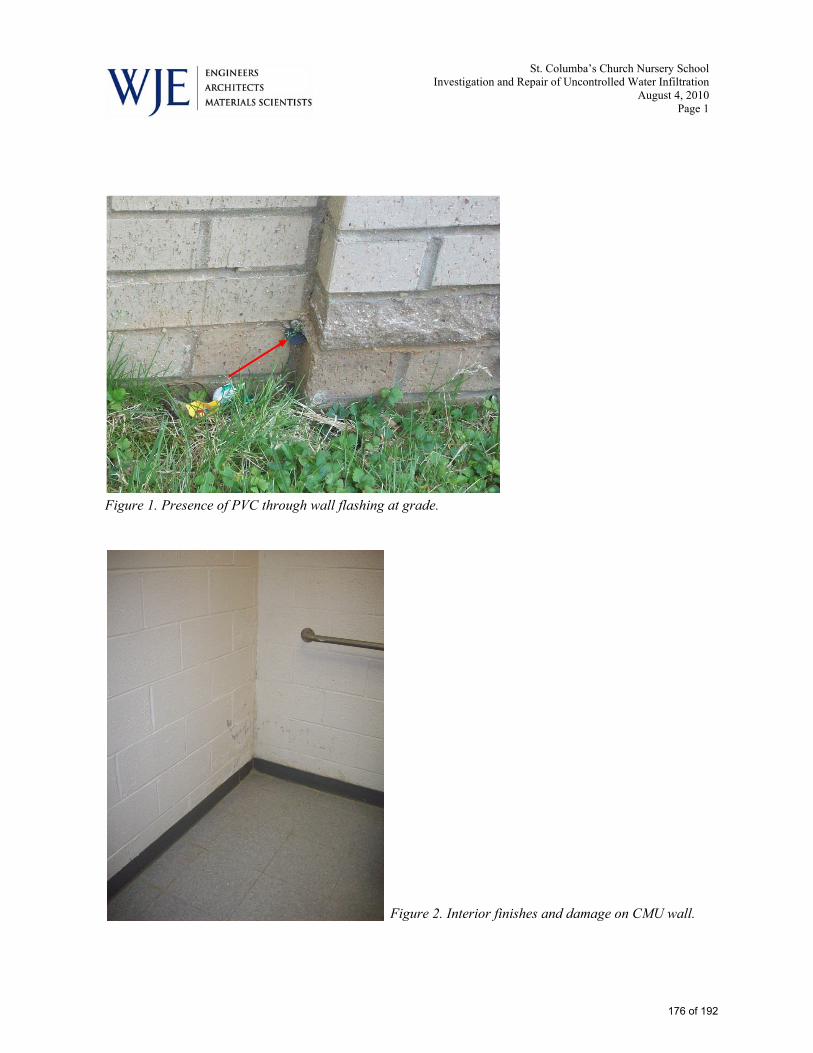
St. Columba’s Church Nursery School Investigation and Repair of Uncontrolled Water Infiltration
August 4, 2010 Page 1
Figure 1. Presence of PVC through wall flashing at grade.
Figure 2. Interior finishes and damage on CMU wall.
176 of 192
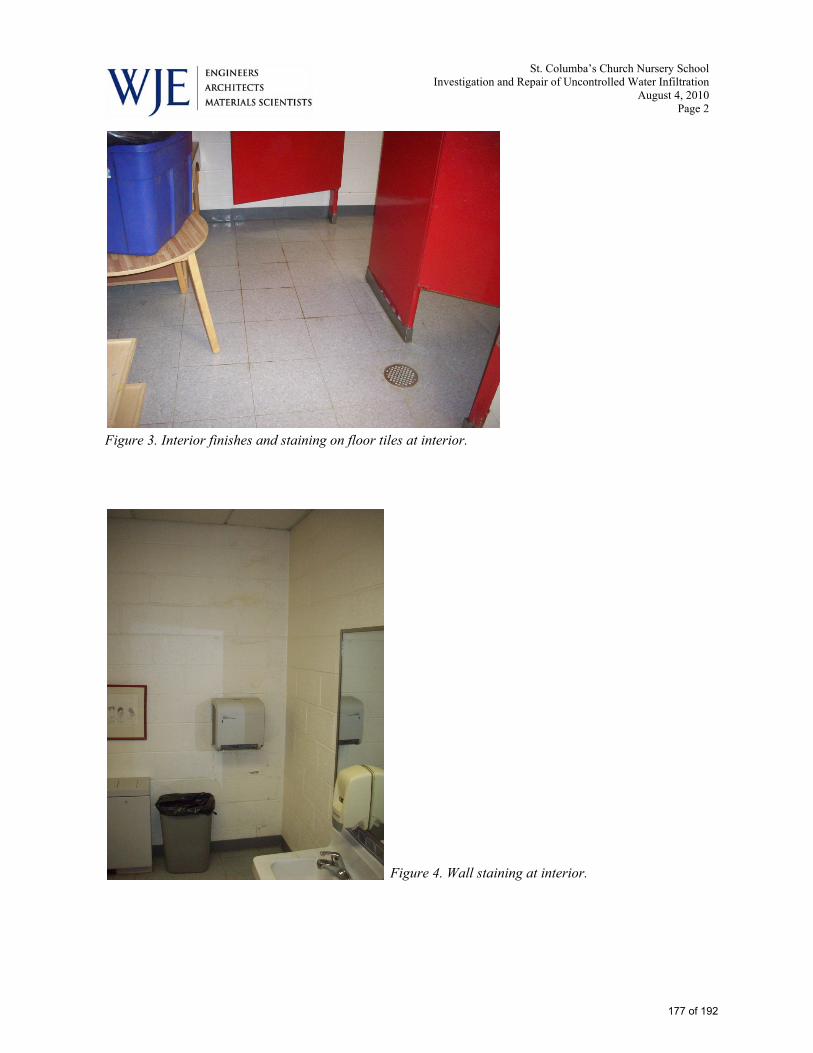
St. Columba’s Church Nursery School Investigation and Repair of Uncontrolled Water Infiltration
August 4, 2010 Page 2
Figure 3. Interior finishes and staining on floor tiles at interior.
Figure 4. Wall staining at interior.
177 of 192

St. Columba’s Church Nursery School Investigation and Repair of Uncontrolled Water Infiltration
August 4, 2010 Page 3
Figure 5. Wall construction at duct opening.
Figure 6. Inspection pit No. 1
178 of 192

St. Columba’s Church Nursery School Investigation and Repair of Uncontrolled Water Infiltration
August 4, 2010 Page 4
Figure 7. Presence of PVC through wall flashing in inspection pit No. 1
Figure 8. Inspection pit No. 2
179 of 192

St. Columba’s Church Nursery School Investigation and Repair of Uncontrolled Water Infiltration
August 4, 2010 Page 5
Figure 9. Filter fabric and gravel fill in inspection pit No. 2
180 of 192

St. Columba’s Church Nursery School Investigation and Repair of Uncontrolled Water Infiltration
August 4, 2010 Page 6
Figure 10. Day 1 water penetration test locations 1 through 4 (Test location 5 not seen in this view).
181 of 192

St. Columba’s Church Nursery School Investigation and Repair of Uncontrolled Water Infiltration
August 4, 2010 Page 7
Figure 11. Day 1 water penetration test locations 4 and 5 (Test locations 1 through 3 not seen in this view).
182 of 192
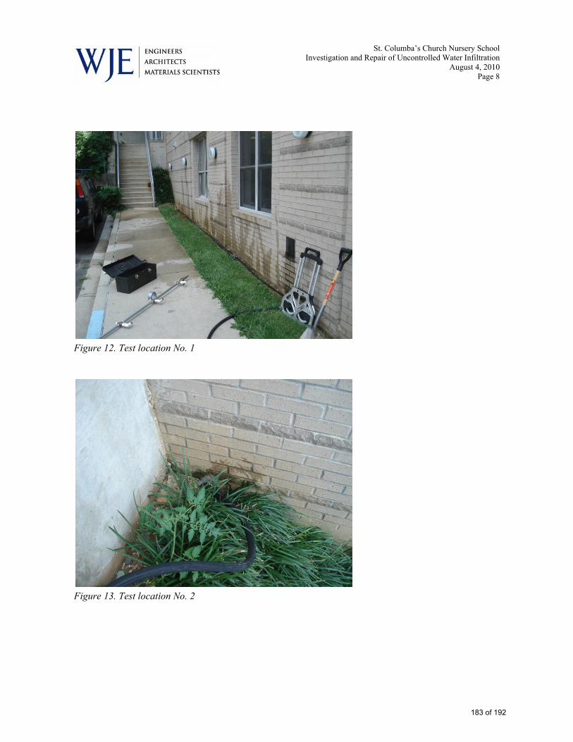
St. Columba’s Church Nursery School Investigation and Repair of Uncontrolled Water Infiltration
August 4, 2010 Page 8
Figure 12. Test location No. 1
Figure 13. Test location No. 2
183 of 192
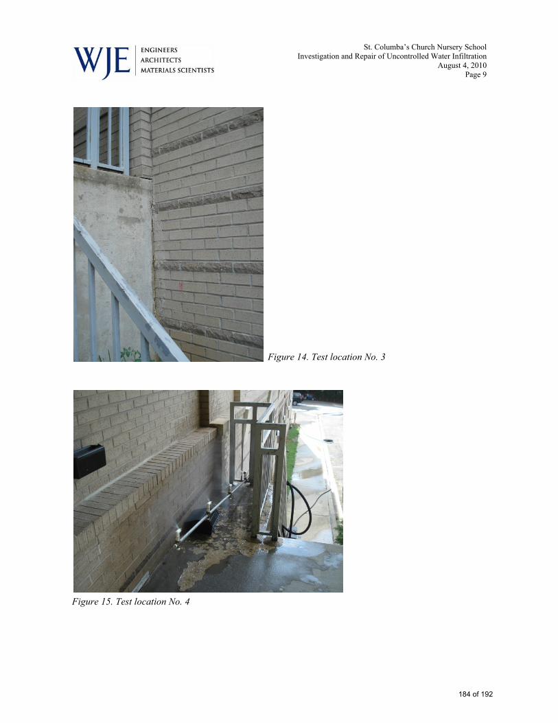
St. Columba’s Church Nursery School Investigation and Repair of Uncontrolled Water Infiltration
August 4, 2010 Page 9
Figure 14. Test location No. 3
Figure 15. Test location No. 4
184 of 192
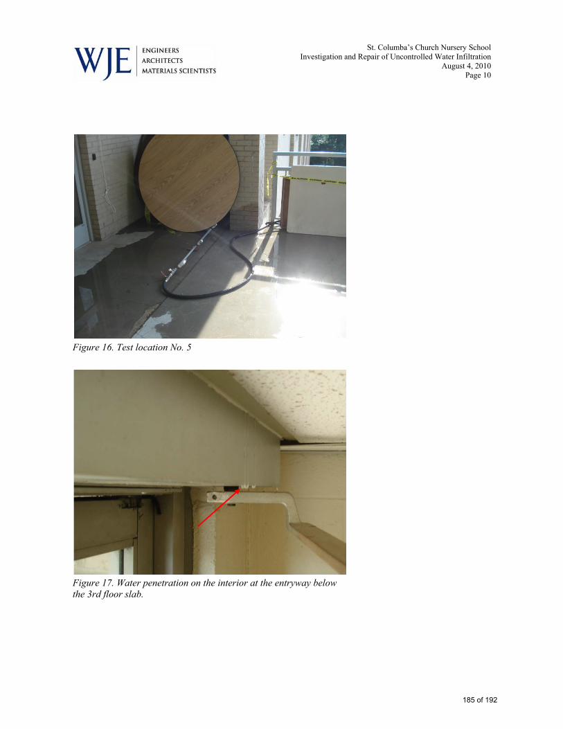
St. Columba’s Church Nursery School Investigation and Repair of Uncontrolled Water Infiltration
August 4, 2010 Page 10
Figure 16. Test location No. 5
Figure 17. Water penetration on the interior at the entryway below the 3rd floor slab.
185 of 192
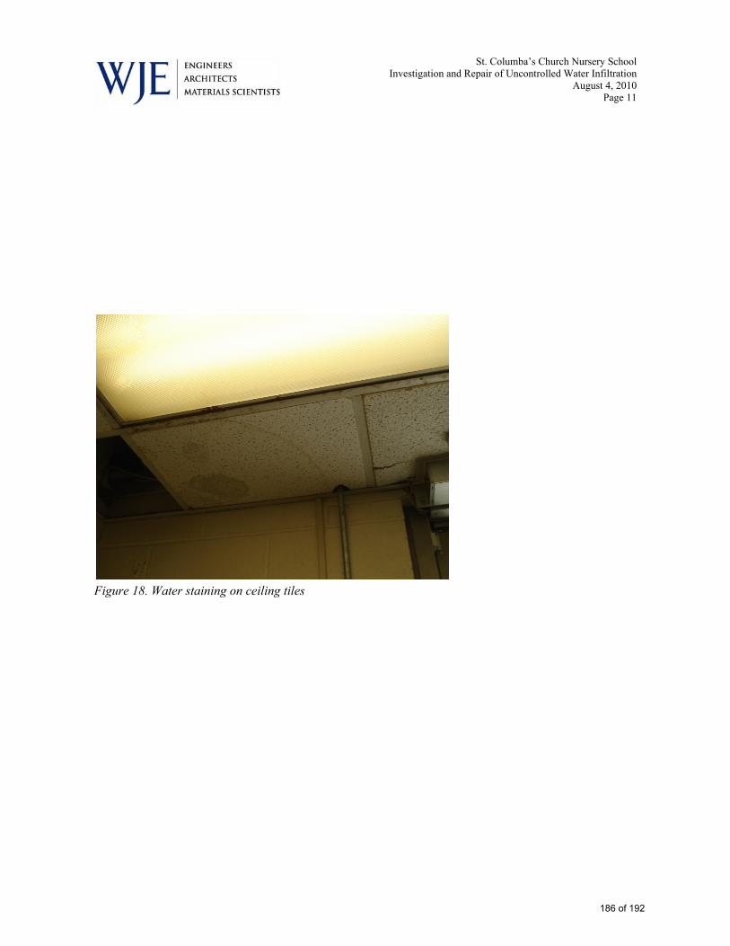
St. Columba’s Church Nursery School Investigation and Repair of Uncontrolled Water Infiltration
August 4, 2010 Page 11
Figure 18. Water staining on ceiling tiles
186 of 192

St. Columba’s Church Nursery School Investigation and Repair of Uncontrolled Water Infiltration
August 4, 2010 Page 12
Figure 19. Day 2 water penetration test locations 6 through 8.
187 of 192

St. Columba’s Church Nursery School Investigation and Repair of Uncontrolled Water Infiltration
August 4, 2010 Page 13
Figure 20. Test location No. 6
Figure 21. Test location No. 7
188 of 192

St. Columba’s Church Nursery School Investigation and Repair of Uncontrolled Water Infiltration
August 4, 2010 Page 14
Figure 22. Test location No. 8
189 of 192

4733 Bethesda Avenue 301.652.8550 (Tel) Suite 550 301.652.1999 (fax) Bethesda, Maryland 20814 www.shinberglevinas.com
Appendix C XII.
Potomac Energy Group – Reference Email
190 of 192

4733 Bethesda Avenue 301.652.8550 (Tel) Suite 550 301.652.1999 (fax) Bethesda, Maryland 20814 www.shinberglevinas.com
191 of 192

4733 Bethesda Avenue 301.652.8550 (Tel) Suite 550 301.652.1999 (fax) Bethesda, Maryland 20814 www.shinberglevinas.com
End of Document
192 of 192