wyatt na ddg12
DESCRIPTION
HF current probeTRANSCRIPT
1 interference technology emc Directory & Design guiDe 2012
The hF CurrenT Probe: Theory and aPPl iCaT ion / WyaT T
This article describes one of the most valuable tools in the EMC engineers “bag of tricks” – the high-frequency
current probe. Current probes are invalu-able for measuring high-frequency com-mon-mode (or “antenna”) currents flowing on wires or cables. Experience has proven that poorly terminated (bonded or filtered) cables are the number-one cause for radi-ated emissions failures at a test facility. By measuring the common-mode (CM) cur-rents (sometimes referred to as “antenna” currents) on these cables it’s possible to troubleshoot and apply fixes to a product right there in your development lab. You can also predict, to a good degree of ac-curacy, whether a given cable current will pass or fail in the measurement chamber. This will save you tons of time trying to apply fixes at the test facility while the clock is ticking away your test time. I’ll also show you several ways to create do-it-yourself (DIY) probes that are quick to make and very useful in a pinch.
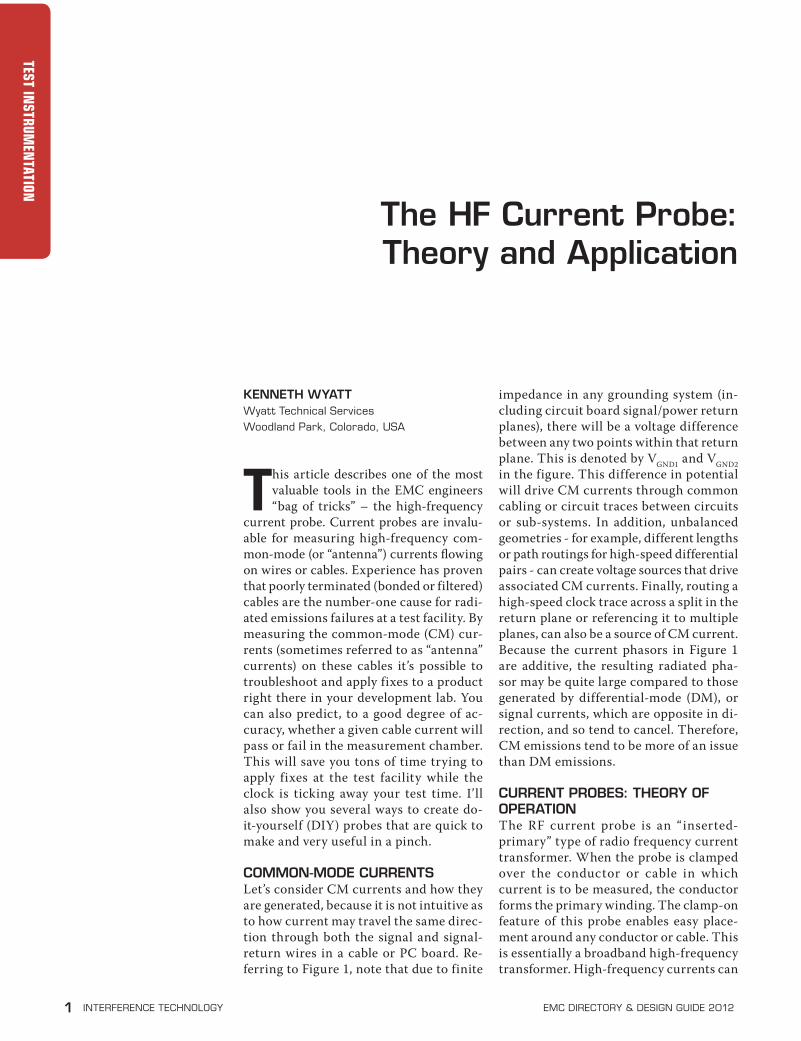
COMMON-MODE CURRENTSLet’s consider CM currents and how they are generated, because it is not intuitive as to how current may travel the same direc-tion through both the signal and signal-return wires in a cable or PC board. Re-ferring to Figure 1, note that due to finite
impedance in any grounding system (in-cluding circuit board signal/power return planes), there will be a voltage difference between any two points within that return plane. This is denoted by VGND1 and VGND2 in the figure. This difference in potential will drive CM currents through common cabling or circuit traces between circuits or sub-systems. In addition, unbalanced geometries - for example, different lengths or path routings for high-speed differential pairs - can create voltage sources that drive associated CM currents. Finally, routing a high-speed clock trace across a split in the return plane or referencing it to multiple planes, can also be a source of CM current. Because the current phasors in Figure 1 are additive, the resulting radiated pha-sor may be quite large compared to those generated by differential-mode (DM), or signal currents, which are opposite in di-rection, and so tend to cancel. Therefore, CM emissions tend to be more of an issue than DM emissions.
CURRENT PROBES: THEORY OF OPERATIONThe RF current probe is an “inserted-primary” type of radio frequency current transformer. When the probe is clamped over the conductor or cable in which current is to be measured, the conductor forms the primary winding. The clamp-on feature of this probe enables easy place-ment around any conductor or cable. This is essentially a broadband high-frequency transformer. High-frequency currents can
The HF Current Probe: Theory and Application
KENNETH WYATTWyatt technical servicesWoodland Park, colorado, usA
TEST InSTrum
EnTaTIon
2 interference technology emc Directory & Design guiDe 2012
The hF CurrenT Probe: Theory and aPPl iCaT ion / WyaT T
be measured in cables without physically disturbing the circuit.
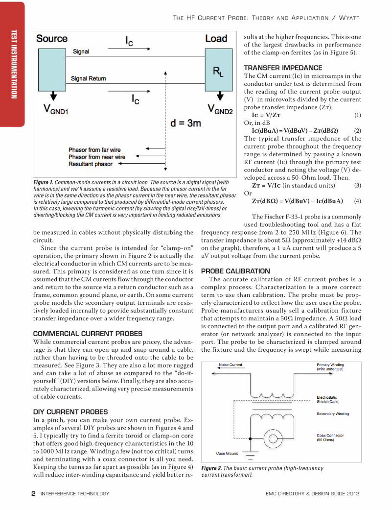
Since the current probe is intended for “clamp-on” operation, the primary shown in Figure 2 is actually the electrical conductor in which CM currents are to be mea-sured. This primary is considered as one turn since it is assumed that the CM currents flow through the conductor and return to the source via a return conductor such as a frame, common ground plane, or earth. On some current probe models the secondary output terminals are resis-tively loaded internally to provide substantially constant transfer impedance over a wider frequency range.
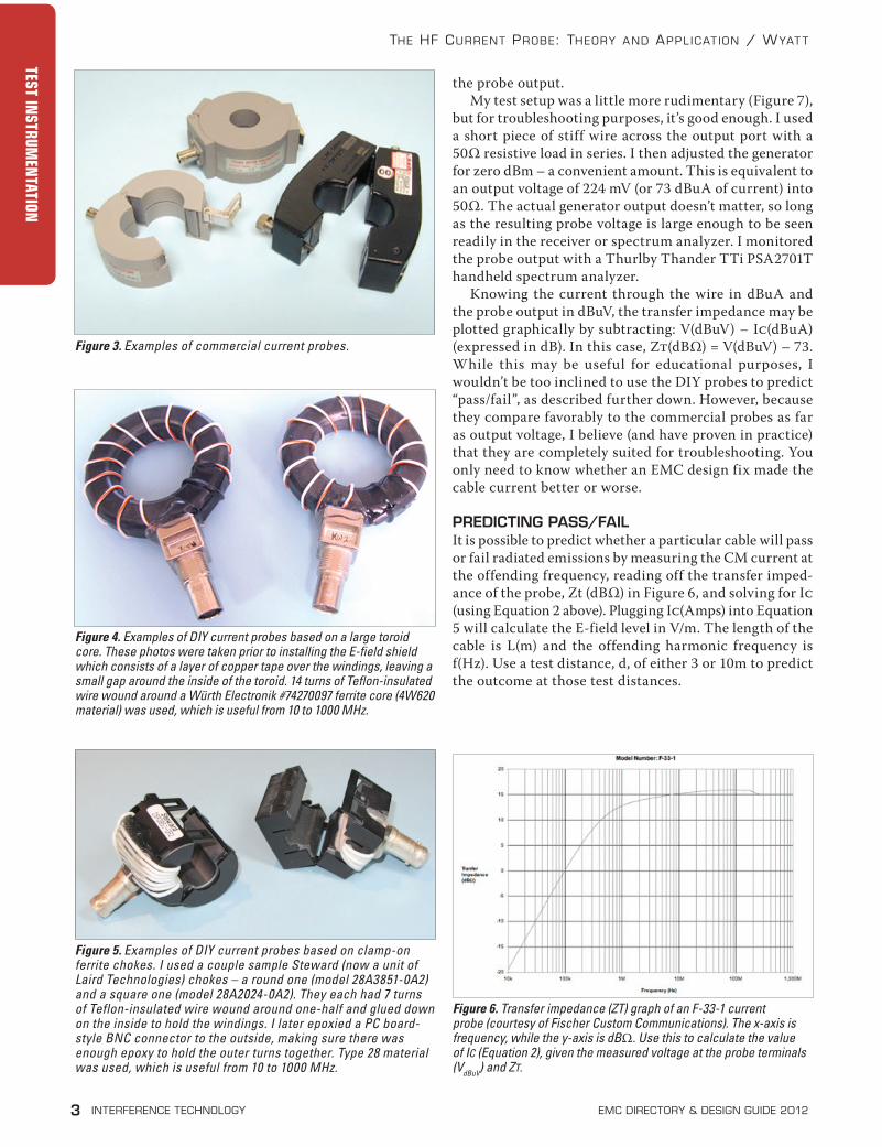
COMMERCIAL CURRENT PROBESWhile commercial current probes are pricey, the advan-tage is that they can open up and snap around a cable, rather than having to be threaded onto the cable to be measured. See Figure 3. They are also a lot more rugged and can take a lot of abuse as compared to the “do-it-yourself” (DIY) versions below. Finally, they are also accu-rately characterized, allowing very precise measurements of cable currents.
DIY CURRENT PROBESIn a pinch, you can make your own current probe. Ex-amples of several DIY probes are shown in Figures 4 and 5. I typically try to find a ferrite toroid or clamp-on core that offers good high-frequency characteristics in the 10 to 1000 MHz range. Winding a few (not too critical) turns and terminating with a coax connector is all you need. Keeping the turns as far apart as possible (as in Figure 4) will reduce inter-winding capacitance and yield better re-
sults at the higher frequencies. This is one of the largest drawbacks in performance of the clamp-on ferrites (as in Figure 5).
TRANSFER IMPEDANCEThe CM current (Ic) in microamps in the conductor under test is determined from the reading of the current probe output (V) in microvolts divided by the current probe transfer impedance (zt).
ic = V/zt (1)Or, in dB
ic(dBuA) = V(dBuV) – zt(dBΩ) (2)The typical transfer impedance of the current probe throughout the frequency range is determined by passing a known RF current (Ic) through the primary test conductor and noting the voltage (V) de-veloped across a 50-Ohm load. Then,
zt = V/ic (in standard units) (3)Or
zt(dBΩ) = V(dBuV) – ic(dBuA) (4)
The Fischer F-33-1 probe is a commonly used troubleshooting tool and has a flat
frequency response from 2 to 250 MHz (Figure 6). The transfer impedance is about 5Ω (approximately +14 dBΩ on the graph), therefore, a 1 uA current will produce a 5 uV output voltage from the current probe.
PROBE CALIBRATIONThe accurate calibration of RF current probes is a
complex process. Characterization is a more correct term to use than calibration. The probe must be prop-erly characterized to reflect how the user uses the probe. Probe manufacturers usually sell a calibration fixture that attempts to maintain a 50Ω impedance. A 50Ω load is connected to the output port and a calibrated RF gen-erator (or network analyzer) is connected to the input port. The probe to be characterized is clamped around the fixture and the frequency is swept while measuring
Figure 1. Common-mode currents in a circuit loop. The source is a digital signal (with harmonics) and we’ ll assume a resistive load. Because the phasor current in the far wire is in the same direction as the phasor current in the near wire, the resultant phasor is relatively large compared to that produced by differential-mode current phasors. In this case, lowering the harmonic content (by slowing the digital rise/fall-times) or diverting/blocking the CM current is very important in limiting radiated emissions.
Figure 2. The basic current probe (high-frequencycurrent transformer).
TEST InSTrum
EnTaTIon
3 interference technology emc Directory & Design guiDe 2012
The hF CurrenT Probe: Theory and aPPl iCaT ion / WyaT T
the probe output.My test setup was a little more rudimentary (Figure 7),
but for troubleshooting purposes, it’s good enough. I used a short piece of stiff wire across the output port with a 50Ω resistive load in series. I then adjusted the generator for zero dBm – a convenient amount. This is equivalent to an output voltage of 224 mV (or 73 dBuA of current) into 50Ω. The actual generator output doesn’t matter, so long as the resulting probe voltage is large enough to be seen readily in the receiver or spectrum analyzer. I monitored the probe output with a Thurlby Thander TTi PSA2701T handheld spectrum analyzer.
Knowing the current through the wire in dBuA and the probe output in dBuV, the transfer impedance may be plotted graphically by subtracting: V(dBuV) – Ic(dBuA) (expressed in dB). In this case, zt(dBΩ) = V(dBuV) – 73. While this may be useful for educational purposes, I wouldn’t be too inclined to use the DIY probes to predict “pass/fail”, as described further down. However, because they compare favorably to the commercial probes as far as output voltage, I believe (and have proven in practice) that they are completely suited for troubleshooting. You only need to know whether an EMC design fix made the cable current better or worse.
PREDICTING PASS/FAILIt is possible to predict whether a particular cable will pass or fail radiated emissions by measuring the CM current at the offending frequency, reading off the transfer imped-ance of the probe, zt (dBΩ) in Figure 6, and solving for Ic (using Equation 2 above). Plugging Ic(Amps) into Equation 5 will calculate the E-field level in V/m. The length of the cable is L(m) and the offending harmonic frequency is f(Hz). Use a test distance, d, of either 3 or 10m to predict the outcome at those test distances.
TEST InSTrum
EnTaTIon
Figure 4. Examples of DIY current probes based on a large toroid core. These photos were taken prior to installing the E-field shield which consists of a layer of copper tape over the windings, leaving a small gap around the inside of the toroid. 14 turns of Teflon-insulated wire wound around a Würth Electronik #74270097 ferrite core (4W620 material) was used, which is useful from 10 to 1000 MHz.
Figure 5. Examples of DIY current probes based on clamp-on ferrite chokes. I used a couple sample Steward (now a unit of Laird Technologies) chokes – a round one (model 28A3851-0A2) and a square one (model 28A2024-0A2). They each had 7 turns of Teflon-insulated wire wound around one-half and glued down on the inside to hold the windings. I later epoxied a PC board-style BNC connector to the outside, making sure there was enough epoxy to hold the outer turns together. Type 28 material was used, which is useful from 10 to 1000 MHz.
Figure 3. Examples of commercial current probes.
Figure 6. Transfer impedance (ZT) graph of an F-33-1 current probe (courtesy of Fischer Custom Communications). The x-axis is frequency, while the y-axis is dBΩ. Use this to calculate the value of Ic (Equation 2), given the measured voltage at the probe terminals (VdBuV) and Zt.

4 interference technology emc Directory & Design guiDe 2012
The hF CurrenT Probe: Theory and aPPl iCaT ion / WyaT T
the enclosure. The connectors simply poked up through cutouts in the rear metal shield.
While using a current probe to measure the CM cur-rent flowing on the outside of the USB cable under test, I simply jammed the screwdriver blade of my Swiss Army knife between the connector bonding fingers and metal chassis enclosure and was able to drop the overall cable currents by 10 to 15 dB.
(5)Once you’ve determined a particular cable has CM cur-
rents that may cause a RE failure, you should to examine the connector where the cable is attached to the product enclosure. Very often, I find poor or non-existent bonding between the connector shield and enclosure shield. These points must be bonded well to permit the CM currents to flow back to their source within the product, avoiding associated cable radiation. Please refer to my previous articles on troubleshooting radiated emissions for more information (references below).
REAL-WORLD TROUBLESHOOTING EXAMPLE
As previously mentioned, one of the most common sources of radiated emissions is due to poorly bonded connectors mounted on shielded product enclosures. This occurs es-pecially if the connectors are circuit board mounted and penetrate loosely through the shielded enclosure. Poor-ly bonded connectors allow internally generated CM currents to leak out and flow on the outside of I/O, mouse or keyboard cables. This will also allow ESD discharges inside the product – more bad news. If these currents are allowed out of the enclosure, the at-tached cables will act as radiating an-tennas – often resonating around 300 MHz, due to their typical 1m length.
This was the case for a new digitiz-ing oscilloscope prototype I worked on recently. The I/O connectors were all soldered onto the PC board and the board was fastened to the rear half of
Figure 7. I used a short wire and 50Ω load (two parallel 100Ω resistors) across the generator output for probe characterization. Obviously, there are shortcomings at higher frequencies, due to the inductance of the wire. In fact, the system impedance starts to go capacitive at 100 MHz and it’s difficult to keep a fixed 224 mV across the load resistor with frequency. Figure 8 Transfer impedance (Zt) graph of a commercial current
probe versus the DIY toroidal probe. The x-axis is frequency, while the y-axis is dBΩ. Note that the commercial probe is only designed and characterized to 250 MHz, so the data above that, while interesting, is probably not valid. The DIY probe, as well, performs poorly above 200 MHz and frankly, the wire loop used to introduce a “calibrated” current (while as short as possible) affects the measurement, as well.
Figure 9. Probe output voltage (Vout) graph of a commercial current probe versus the DIY toroidal probe. The x-axis is frequency, while the y-axis is dBuV. This shows that the probes are very comparable in output voltage versus frequency. For troubleshooting purposes, absolute accuracy is not required - just consistency in measurements. All one really needs to know is, “ did the fix I implemented make the CM current go up or down?” The DIY probe works well for this.
TEST InSTrum
EnTaTIon

5 interference technology emc Directory & Design guiDe 2012
The hF CurrenT Probe: Theory and aPPl iCaT ion / WyaT T
TROUBLESHOOTING TIPS USING CURRENT PROBES
Here are a few troubleshooting tips using current probes.
1. When evaluating the harmonics on a cable by using a current probe, if sliding the probe back and forth changes the harmonic levels, part of the coupling may be near-field, rather than conducted.
2. When using a pair of current probes; one on each of two cables, if the harmonics are the same in each, the source is in the middle. If one cable has stronger harmonics, then you’ll want to work on that side first. See Figure 12 below.
3. Measuring the currents on two suspect legs of a dipole should read the same. Placing the two suspect legs through the same current probe should cause a big decrease due to current cancellation. See Figure 12 below.
4. When measuring video cable currents and large cable movements cause big changes in amplitude, the coupling is likely inductive - otherwise, it’s more likely conductive.
5. If you suspect inductive coupling, the phase at the victim will be 180-degrees from the source. This may be observed on an oscilloscope with H-field probes or cur-rent probes. Try syncing the scope trigger at the source using a scope probe.
My colleague, Doug Smith, has many more examples on how to use current probes for measuring cable and PC
board resonances, injecting pulses for troubleshooting, interpreting the relative phase of common-mode cur-rents and troubleshooting ESD issues. Refer to the references below.
SUMMARYUse of a current probe is vital
during the troubleshooting process. Poorly bonded cable connectors can be readily identified and fixed. The radiated E-field from a product I/O cable may be calculated by measuring the high-frequency common-mode currents f lowing in the cable. All this may be performed right at the designer’s workbench and without the expense of a third-party test facility or shielded chamber.
REFERENCES - PAPERS• [1] Mat Aschenberg & Charles
The solution was to fabricate a custom shim with spring-fingers that would slip over all the connectors cre-ating a firm bond between the connector ground shell and inside of the shielded enclosure. More and more low-cost products are relying on PC board mounted I/O connec-tors as a cost-cutting measure. Any time you see this, be prepared to carefully examine the bonding between the connector ground shell and the shielded enclosure.
TEST InSTrum
EnTaTIon
Figure 11. Cables should be tested individually. Here, I have a current probe clamped around the cable under test and am monitoring the harmonics with a simple hand-held spectrum analyzer. As I ground the connector shell to the chassis with the Swiss Army screwdriver blade, the harmonics were reduced 10-15 dB!
Figure 10. Probe output voltage (Vout) graph of a commercial current probe versus two DIY toroidal probes and two different clamp-on probes. The x-axis is frequency, while the y-axis is dBuV. This shows that all these probes are very comparable in output voltage versus frequency and therefore, useful for troubleshooting purposes. Just don’t try using the DIY probes to determine “pass or fail” predictions. Commercial probes are better-suited for that.

6 interference technology emc Directory & Design guiDe 2012
The hF CurrenT Probe: Theory and aPPl iCaT ion / WyaT T
Grasso, Radiation from Common-Mode Currents – Beyond 1 GHz (Three Methods Compared)
• [2] Dave Eckhardt, Homebrew Clamp-On Current Probe, private correspondence (January 2009), Email: [email protected].
• [3] Jasper Goodblood, Electromagnetic Compatibility, 1990, Pren-tice Hall, pages 31-34.
• [4] Michel Mardiguian, EMI Troubleshooting Techniques, Mc-Graw-Hill, 2000, pages 39-49.
• [5] Montrose & Nakauchi, Testing for EMC Compliance, 2004, Wiley Interscience, pages 116-124, 143-145, and 159-161.
• [6] Henry Ott, Electromagnetic Compatibility Engineering, Wiley, 2009, pages 690-693.
• [7] Henry Ott, Measuring Common-Mode Currents on Cables, www.hottconsultants.com/techtips/tips-cm.html
• [8] Clayton Paul, Introduction to Electromagnetic Compatibility (2nd Edition), Wiley Interscience, 2006, pages 518-532.
• [9] Ridao, Carrasco, Galvin and Franquelo, Implementation of low cost current probes for conducted EMI interference measure in Power Systems, EPE 1999 (Lausanne).
• [10] H. Ward Silver, Hands-On Radio column, Detecting RF – Part 2, QST, August 2011, page 54-55.
• [11] Doug Smith, Current Probes, More Useful Than You Think, IEEE EMC Symposium 1998, http://emcesd.com/pdf/iprobe98.pdf.
• [12] Doug Smith, The Two Current Probe Puzzle, http://emcesd.com/tt061999.htm.
• [13] Doug Smith, Using Current Probes to Inject Pulses for Trou-bleshooting, http://emcesd.com/tt2007/tt120307.htm Part 1, http://emcesd.com/tt2009/tt030309.htm Part 2.
• [14] Doug Smith, Using Current Probes to Measure Cable Resonance, http://emcesd.com/tt2008/tt010108.htm.
• [15] Doug Smith, Measuring and Interpreting the Relative Phase of Common Mode Currents, http://emcesd.com/tt2008/tt030208.htm.
• [16] Doug Smith, Using a Comb Generator with a Pair of Current Probes to Measure Cable Resonance, http://emcesd.com/tt2009/tt110709.htm.
• [17] Doug Smith, Using Current Probes to Inject Pulses for Trouble-shooting (Board Resonances), http://emcesd.com/tt2010/tt010110.htm.
• [18] Doug Smith, Predicting Cable Emissions from Common Mode Current, http://emcesd.com/tt2006/tt030106.htm.
• [19] Douglas Smith, High Frequency Measurements and Noise in Electronic Circuits, Van Nostrand Reinhold, 1993, pages 41-44, 159-
182, 192-209.• [20] Allen Wolff, Building a Ferrite Core Antenna Current Probe, Technical Cor-respondence, QST, August 2009, page 53.• [21] Kenneth Wyatt, Troubleshoot-ing Radiated Emissions Using Low-Cost Bench-Top Methods, Interference Technology (ITEM) – EMC Directory & Design Guide 2011, May 2011, page 10-21, http://www.interferencetechnology.com/uploads/media/Wyatt_DDG11.pdf.• [22] Kenneth Wyatt , Trouble-shooting Radiated Emissions – Three Case Studies, InCompliance Magazine, October 2011, http://www.incompliancemag.com/index.php?option=com_content&view=article&id=818:troubleshooting-radiated-emissions-three-
case-studies&catid=27:testing&Itemid=136.
REFERENCES - SUPPLIERS• [23] Fischer Custom Communications (FCC), Phone: (310) 303-3300,
Email: [email protected], Web: www.fischercc.com. They provide a very wide range of HF current probes – their specialty.
• [24] Laird Technologies, Web: http://www.lairdtech.com/Products/EMI-Solutions/. They offer a complete line of ferrite cores and chokes.
• [25] Pearson Electronics, Phone: (650) 494-6444, Email: [email protected], Web: www.pearsonelectronics.com. They have a good selection of probes.
• [26] Rhode & Schwartz USA, Phone: (888) 837-8772, Email: [email protected], Web: www.rohde-schwartz.us. They have a very limited selection.
• [27] Solar Electronics, Phone: (800) 952-5302, Email: [email protected], Web: www.solar-emc.com. They have a limited selection.
• [28] Teseq USA, Phone: (732) 417-0501, Email: [email protected], Web: www.teseq.us. They have a very limited selection.
• [29] Thurlby Thander Instruments, Phone: +44-1480-412451, Email: [email protected], Web: http://www.tti-test.com/contact-tti.htm. They offer a low-cost handheld spectrum analyzer for under $2,000 USD.
• [30] Würth Electronics Midcom, (605) 886-4385, [email protected], www.we-online.com. I used one of their large ferrite cores for my DIY current probe.
Kenneth Wyatt, Sr. EMC Engineer, Wyatt Technical Services LLC, holds degrees in biology and electronic engineering and has worked as a senior EMC engineer for Hewlett-Packard and Agilent Technologies for 21 years. He also worked as a product development engineer for 10 years at various aerospace firms on projects ranging from DC-DC power converters to RF and microwave systems for shipboard and space systems. A prolific author and presenter, he has written or presented topics including RF amplifier design, RF network analysis software, EMC design of products and EMC troubleshooting techniques. He has been published in magazines such as, RF Design, EMC Design & Test, Electronic Design, InCompliance, Inter-ference Technology, Microwave Journal, HP Journal and several others. Wyatt is a senior member of the IEEE and a long time member of the EMC Society where he serves as their official photographer. He is also a member of the dB Society and is a licensed amateur radio operator. Contact Wyatt at [email protected]. His website is www.emc-seminars.com.
Figure 12. When measuring two cables from a system and the harmonic currents are approximately the same (point 1 is the same as point 2), the source is at the center (the EUT) and the two cables are acting as a dipole antenna. You may notice a peak in harmonic strength at the half-have length of the two cables combined. If the harmonic currents are larger in one side or the other, then you’ ll want to troubleshoot just that cable.
TEST InSTrum
EnTaTIon