www.ischool.drexel.edu info 424 team project practicum week 5 – software design specification...
TRANSCRIPT

www.ischool.drexel.edu
INFO 424Team Project Practicum
Week 5 – Software Design Specification
Glenn BookerNotes mostly from Prof. Hislop, INFO 200, and INFO 355
1INFO 424 Week 5

www.ischool.drexel.edu
Agenda• Reviews
• Project status
• Submitting documents
• Launch Reports
• Software Design Specification
2INFO 424 Week 5

www.ischool.drexel.edu
Reviews, Walkthroughs and Inspections
• A family of related techniques• Review / inspect
– To examine closely– With an eye toward correction or
appraisal
• People (peers) are the examiners– Not machines
3INFO 424 Week 5

www.ischool.drexel.edu
Purpose of reviews• Catching errors
– Sooner– More and different– Breaking frame of reference
• Improving communication– Crossing organizational
boundaries
• Providing Education• Making software visible
4INFO 424 Week 5

www.ischool.drexel.edu
Formal Technical Review• One style of review that is
– Formal• Scheduled event• Defined procedure• Reported result
– Technical• Not schedule• Not budget
– Independent review team• Producers not present• Product must stand on its own
5INFO 424 Week 5

www.ischool.drexel.edu
The Review Team
Leader Reviewers Recorder
6INFO 424 Week 5
www.ischool.drexel.edu
Team Leader - Run the Meeting• Act as chairperson
– Opening and introductions– Procedure guide – Closing
• Act as facilitator– Controlling level of participation
• Enough but not too much
– Conflict resolution
• Terminate the meeting if unproductive
7INFO 424 Week 5

www.ischool.drexel.edu
Reviewers - Tasks• Prepare before
– Thorough review of materials
• Participate– Be there
• Can’t arrive late or leave early
– Act professionally• Set aside personal agendas• Big egos and shyness
– Positive and negative comments• Balance; courtesy; preserving what’s good
8INFO 424 Week 5

www.ischool.drexel.edu
Recorder• Selection
– Any competent reviewer– Single or multiple recorders– Rotating responsibility within a meeting– Leaders as recorders = bad idea
• Have too much to do• Separation of power
• Task: Get it in writing– Basis for report
9INFO 424 Week 5

www.ischool.drexel.edu
Review Report• Purpose
– Tell managers the outcome– Early warning system for major problems– Provide historical record
• For process improvement• For tracking people involved with projects
• Contents– Summary– Product issues– Other related issues
10INFO 424 Week 5

www.ischool.drexel.edu
Summary• Highly effective technique
• Easily accessible– No special technology required
• Not used nearly enough– Culture and habit
• DO IT!
11INFO 424 Week 5

www.ischool.drexel.edu
Requirements Review
• Goal: find and document as many requirements issues as possible
• Result: Simple review report– Soft and hardcopy to me– Copy to the team whose product
you reviewed
• Time expenditure– 2 hour prep– 2 hour team meeting
12INFO 424 Week 5

www.ischool.drexel.edu
Blackboard Class Site
• Submit final products as attachments– Communication…Group Pages…<your team
name>…Group Discussion Board…Team Products
• Submit drafts or edits by individuals– Communication…Group Pages…<your team
name>…Group Discussion Board…Drafts
• Use the file name forms discussed in the syllabus– Good for the posting title, but essential for the
attached file
13INFO 424 Week 5

www.ischool.drexel.edu
Launch Reports
• Overview section– Should be several paragraphs– Define the product
• What is it? What does it do?– Motivate the problem
• Why is this product needed?– Describe the solution
• How will the product solve the problem?– Identify the user
• Who will buy and use the system?– Explain the benefit
• Why will this be a great thing?
14INFO 424 Week 5

www.ischool.drexel.edu
Launch Report
• Overview opening paragraph– “The Student Course Request System
(SCRS) will allow students to have a stronger role within the course scheduling process. Currently, student input into the scheduling process is insignificant and lacks student comments, suggestions and concerns. The new system will provide a method for student input for course scheduling.”
15INFO 424 Week 5

www.ischool.drexel.edu
Launch Reports
• Feature highlights– Just bullets, but more than phrases or single
words– Minimize duplication with overview
• Team communication– Try to identify at least one actual meeting time– Doesn’t have to be in person
16INFO 424 Week 5

www.ischool.drexel.edu
Launch Reports
• Objectives– Focus on what will make the team successful
in this cycle
• Schedule– Use the Project Plan and Activity Summary
in the Project Tracking workbook
17INFO 424 Week 5

www.ischool.drexel.edu
SDS
18INFO 424 Week 5
www.ischool.drexel.edu
Software Design Specification
• Shift in focus– SRS: What will the system do?– SDS: How will it do it?
• SDS builds on the SRS– Everything in the SDS should tie to a
requirement in the SRS
• Diagrams are key and required
19INFO 424 Week 5

www.ischool.drexel.edu
SDS Document
• Introduction
• Architectural Description
• Interface Description
• Detailed Design
• Patterned after IEEE std 1016-1998
20INFO 424 Week 5
www.ischool.drexel.edu
SDS Document
• Introduction– Much like the SRS– Copy (but update) the sections– Allows each document to stand on its own
21INFO 424 Week 5

www.ischool.drexel.edu
SDS Document
• Architectural Description– High level view of the design
• Identifies and discusses the “big pieces” of your product
– Diagrams are required (but don’t overdo it)• Class diagram• Sequence diagram, if appropriate• Others, e.g. DFD and ERD• Include text description for diagrams
– Subsections, if desired• Organize by subsystem or major component (class)
22INFO 424 Week 5

www.ischool.drexel.edu
Example: Architectural Overview
Existing Appointment Management
System
Friday, October 21, 2005
Page 1
PARS Components Diagram
PARS Internal Database
Data File
Application InterfaceApplication Interface
Web InterfaceWeb Interface
SMS Messages Service Provider
Email Service Provider
PARS
(Patient Appointment Reminder System)
How might thesenames be mademore meaningful?
23INFO 424 Week 5
www.ischool.drexel.edu
DFD
Extracted from INFO 200 week 4
24INFO 424 Week 5

www.ischool.drexel.edu
DFD Notation
• Here are Visio examples of the entity, process, and data store shapes, with data flow lines connecting them– If your shapes differ
from this convention, provide a legend
In Visio these shapes are under the Flowchart family not Database
Clerk4. Create new
customer
D2. Customer
New customer data
New custo
mer data
25INFO 424 Week 5

www.ischool.drexel.edu
DFD Scope
• A DFD does not show any kind of business rules for processes – just all possible paths– No decisions, or conditions (if)
• A logical DFD does not show the subsystems involved in a process– We might show a Customer data store, but
don’t specify how or where is it implemented
• Processes may be manual or automated – there is no distinction on a logical DFD
26INFO 424 Week 5

www.ischool.drexel.edu
Rules for Data Flow Diagrams
• Entities never connect to a data store– They must use some process to access or modify
the data– Hence a user or external system can only
connect to one or more processes
• All kinds of entities (users) which appear on the context diagram (or anywhere else in the system documentation) must appear somewhere on the DFD– Otherwise they don’t do anything!
27INFO 424 Week 5

www.ischool.drexel.edu
Rules for Data Flow Diagrams
• Each process will connect to at least one user or external system, and one data store– Each process may send data to one or more
data stores, and/or get data from one or more data stores
– Processes rarely connect to other processes
– Each process needs data flowing in and out of it
– Fix processes which have logically incomplete inputs and outputs
28INFO 424 Week 5
www.ischool.drexel.edu
Rules for Data Flow Diagrams
– Leave in processes which calculate something, make decisions, manipulate data, or organize data
• Data flows pointing away from an entity imply they provide input to the system – Data flows pointing to an entity imply they
receive an output from the system
• Data flows are always directional; use two separate lines if needed
29INFO 424 Week 5
www.ischool.drexel.edu
Rules for Data Flow Diagrams
• Every data store needs data flowing both in and out somewhere on the diagram– Otherwise you have a data black hole = inputs
but no output, or – A miracle = outputs without input
• Data stores do not connect directly to each other– A process is needed to take data from one
data store, and write it to another one30INFO 424 Week 5

www.ischool.drexel.edu
ERD
Extracted from INFO 200 week 5
31INFO 424 Week 5

www.ischool.drexel.edu
Permanent vs. Transient Data
• A key for relational data modeling is that we are primarily concerned with data we need to keep permanently
• Data which is only needed briefly isn’t modeled in an ERD– Major difference between relational and
object-oriented analysis
32INFO 424 Week 5

www.ischool.drexel.edu
Characterize Entities
• Entities are generally one of two types:– A set of data you want to keep permanently
(customer orders, product information, etc.)– A lookup list or table (types of status codes,
shipping rates, tax rates, etc.)
• Data which is transient is generally kept in local variables, and doesn’t appear in an ERD (e.g. change of address info)
33INFO 424 Week 5

www.ischool.drexel.edu
Keep it or not?
• In trying to decide if data needs to be kept, consider whether someone might want to analyze that data in the future– For examples, to look for sales patterns,
trace relocation history, keep record of data changes (who modified what data and when?)
• When in doubt, keep it for now
34INFO 424 Week 5

www.ischool.drexel.edu
Database Notation
• Recall basic notation for cardinality– Only one– Zero or one– One or many– Zero, one, or many– Strictly many
• Now we want to put all the two-entity pairs together, into a single diagram
35INFO 424 Week 5

www.ischool.drexel.edu
ERD
• The Entity-Relationship Diagram (ERD) captures all the entities for our system, and shows the relationships among them (the lines connecting them)
• The relationships all need to have– A verb phrase in at least one direction– Cardinality at both ends
• Now we can add attributes and keys
36INFO 424 Week 5
www.ischool.drexel.edu
Attributes
• Each entity is almost certain to have at least two attributes (often more)– At least one of them is a unique identifier for
each record in the entity, the primary key– Other attributes describe significant
characteristics of the entity• So, about what aspects of the entity do you want
to retain knowledge?• Attributes are also called fields, data items, etc.
37INFO 424 Week 5

www.ischool.drexel.edu
Attributes & Records
• Attributes can be fixed or variable length– We won’t worry about attribute lengths – Don’t specify data types (number, text, date,
etc.) yet unless they’re weird
• A record is a set of attributes from one entity, typically corresponding to one row in a data table
• Ask yourself if an attribute should be a key
38INFO 424 Week 5

www.ischool.drexel.edu
Key Attributes
• An attribute or group of attributes may be a unique identifier, or key, for each entity– Examples are Social Security Number,
driver’s license number, ISBN, Student ID
• If a group of attributes is used, it is a concatenated (or composite or compound) key– {Course number, section number, and
term} could form a concatenated key39INFO 424 Week 5

www.ischool.drexel.edu
Many Keys Possible
• There might be more than one usable key for an entity– Each possible key is called a candidate key– One candidate key is selected to be the
primary key (PK)
• All others are alternate keys (AK)– Example: the electric company may use a
customer ID or account number as a primary key, and your phone number as an alternate key (don’t worry about finding these)
40INFO 424 Week 5

www.ischool.drexel.edu
Primary Key may be Meaningless
• A primary key might correspond to some recognizable attribute – SSN, student ID, ISBN, etc.
• Or it may be completely meaningless– A sequential number, called OrderID
• As long as the primary key is unique for every record, either kind is acceptable
41INFO 424 Week 5

www.ischool.drexel.edu
Foreign Keys
• A foreign key is an attribute which establishes the connection between two entities– A Sales entity might have a foreign key
attribute Customer_ID, which points to all of the data in the Customer entity for the particular customer who placed a given sale
– If that were the case, the primary key in the Customer entity must be Customer_ID
• This type of connection is the heart of relational database modeling
42INFO 424 Week 5
www.ischool.drexel.edu
Foreign Keys
• A foreign key (FK) is an attribute which exists, in an entity other than where it is a primary key (PK), to establish the relationship between the two entities– Primary key must be unique for each record,
but a foreign key value may appear many times
– Only one PK-FK connection is required for the relationship to exist
– Entity with FK generally has a PK of its own
43INFO 424 Week 5

www.ischool.drexel.edu
Other Key Traits
• A PK attribute may also be a FK – Especially for 1:1 relationships
• An associative entity builds a concatenated primary key from more than one entity– Uses a diamond shape inside the normal box
to show its special nature
44INFO 424 Week 5

www.ischool.drexel.edu
Other Relationships
• A many-to-many (non-specific) relationship implies a lot of one-to-many relationships– Often use an associative entity to bridge
between them
• An identifying relationship is when a parent entity’s PK is used as part of the PK for a child entity– Child entity is then considered “weak”
because it depends on the parent45INFO 424 Week 5

www.ischool.drexel.edu
Summary of Key Traits
• The bottom line for keys is:– Each entity must have at least one PK
• More than one PK implies a concatenated key
– Alternate keys are completely optional– Each entity may have from zero to many FK’s– Each FK is a PK in another, related entity– Only one PK-FK relationship is needed to
relate two entities– Some keys are not inherently meaningful data
46INFO 424 Week 5

www.ischool.drexel.edu
Third Normal Form (3NF)
• An ERD should be normalized to third normal form– An entity is in third normal form if every
non-primary key attribute is dependent on the primary key, the whole primary key, and nothing but the primary key
(as in, “Do you swear to tell the truth…”)
47INFO 424 Week 5

www.ischool.drexel.edu
Summary: How to create an ERD
– Define the entities about which you’ll want to keep information
– Define the relationships between those entities
• Must have a verb phrase and both cardinalities– Define the attributes for each entity
• Define the name of each attribute• Identify a primary key for each entity• Identify foreign keys as needed
– Normalize to third normal form (and fix keys as needed)
48INFO 424 Week 5
www.ischool.drexel.edu
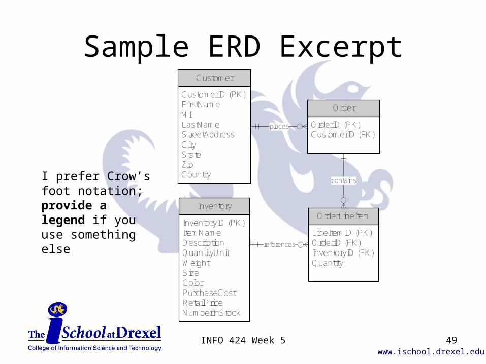
Sample ERD Excerpt
I prefer Crow’s foot notation; provide a legend if you use something else
Customer
CustomerID (PK)FirstNameMILastNameStreetAddressCityStateZipCountry
Order
OrderID (PK)CustomerID (FK)
Inventory
InventoryID (PK)ItemNameDescriptionQuantityUnitWeightSizeColorPurchaseCostRetailPriceNumberInStock
OrderLineItem
LineItemID (PK)OrderID (FK)InventoryID (FK)Quantity
places
references
contains
49INFO 424 Week 5

www.ischool.drexel.edu
UML Diagrams
See INFO 355 weeks 3-5 and my summary of UML diagrams
50INFO 424 Week 5

www.ischool.drexel.edu
UML Diagrams
• If you’re doing object oriented design, you can skip the DFD and ERD approach, and instead focus on– Class diagram– Sequence diagram for use cases
implemented this and previous cycles– If needed, package or deployment diagrams
51INFO 424 Week 5

www.ischool.drexel.edu
Purpose of Class Diagram
• The Class Diagram shows many key characteristics of the system– What classes can exist– Their attributes (data)– Their methods (functions to get to
the data)– How the classes see each other (like
relationship and cardinality)
52INFO 424 Week 5

www.ischool.drexel.edu
Types of Classes
• It often helps to think of three types of classes– Data classes are used to store data, much
like traditional entities in an ERD– Control classes are used to manage
performing a use case, like scripts– Interface classes are the GUI seen by the
user – they are the classes first acted upon, and the only ones actors interact with
53INFO 424 Week 5

www.ischool.drexel.edu
Conceptual Class Diagram Excerpt
-date-time
Sale-quantity
SalesLineItem
-amount
Payment
1
1
Paid-by
11..*Contained-in
Association
Conceptual class
Attribute
Multiplicity
Association label
No methods shown
54INFO 424 Week 5

www.ischool.drexel.edu
Analogies to ERD
ERD has Class Diagram has
Entities Classes
Relationships Associations
Cardinality Multiplicity
Data elements or attributes
Attributes
55INFO 424 Week 5

www.ischool.drexel.edu
Multiplicity
• Here ‘*’ means many, but by itself it means ‘0, 1, or many’
• ‘1..*’ means one or many
• ‘1..40’ means a range from 1 to 40
• ‘n’ means only the value of ‘n’
• Obsolete (from UML 1.x):– ‘a, b, c’ means only a, b, and c are allowable
values, e.g. ‘2, 5, 7’
56INFO 424 Week 5

www.ischool.drexel.edu
Adding Attributes
• Don’t worry about “keys” for defining associations to other classes, such as primary and foreign keys
• Don’t worry about data normalization per se
• Focus only on data characteristics of each class
57INFO 424 Week 5
www.ischool.drexel.edu
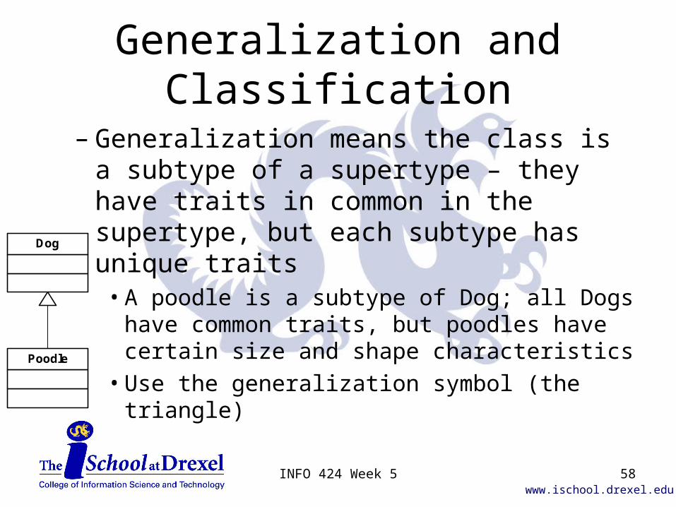
Generalization and Classification
– Generalization means the class is a subtype of a supertype – they have traits in common in the supertype, but each subtype has unique traits
• A poodle is a subtype of Dog; all Dogs have common traits, but poodles have certain size and shape characteristics
• Use the generalization symbol (the triangle)
Dog
Poodle
58INFO 424 Week 5

www.ischool.drexel.edu
Derived Attributes
• A Note box (text box with upper right corner dog-eared) can be used to show how a derived attribute is calculated – This violates 3NF in ERD terminology
duration = enddate - startdate-startdate : Date-enddate : Date-/duration : Integer
Task
Note box
59INFO 424 Week 5

www.ischool.drexel.edu
Sequence diagrams
From INFO 355 week 4
60INFO 424 Week 5
www.ischool.drexel.edu
Interaction Diagrams
• Interaction diagrams describe how one or more actors interact with the system to perform one use case
• The development of interaction diagrams motivates the development of methods (i.e.
making them up), which become part of the class diagram
61INFO 424 Week 5
www.ischool.drexel.edu
Interaction Diagrams
• Major consistency point – the classes, associations and methods from your sequence diagrams should appear in your class diagram!
62INFO 424 Week 5

www.ischool.drexel.edu
Generic Sequence Diagram:ClassA :ClassB :ClassC :ClassD
msg1()
msg2()
msg3()
msg4()
msg5()
msg6()
No returns are shown. The primary actor may be shown.
Notice that messages may go right-left as well as left-right.
63INFO 424 Week 5

www.ischool.drexel.edu
Where to begin?
• To develop an interaction diagram, use the use case documentation to– Identify the primary actor– Use the MVC (or interface, control, and data
objects) pattern to make up the objects which will be used to follow the main success scenario
– Label messages appropriately to read, move, and analyze data as needed
64INFO 424 Week 5

www.ischool.drexel.edu
Self-called Messages
• An object may call its own methods– The message line makes a U turn to the line
from which it started, and is still labeled with the name of the method name
Message2
Object1
65INFO 424 Week 5

www.ischool.drexel.edu
Object Creation and Deletion
• A special notation is used for the creation of an object during a use case– The message points to the new object, and
the message is labeled ‘new’ or ‘create’
• When an object is no longer needed, it is deleted– Message is labeled ‘close’ or ‘delete’
66INFO 424 Week 5

www.ischool.drexel.edu
Conditionals and Loops
• See the “Summary of UML Diagrams” and INFO 355 week 4 lecture notes for details on how to use conditionals and loops in a sequence diagram– Recall that each message in a sequence
diagram implies which class implements that method (the target of the message), and the communication between classes implies an association exists between them
67INFO 424 Week 5

www.ischool.drexel.edu
Class Diagram for slide 63
+msg1()
ClassA
+msg2()+msg5()
ClassB
+msg3()+msg4()
ClassC
+msg6()
ClassD
68INFO 424 Week 5

www.ischool.drexel.edu
Interface Diagram
69INFO 424 Week 5

www.ischool.drexel.edu
SDS Document
• Interface Description– User interface
• Screen hierarchy diagram• Screen shots or layouts
– Menus, etc.
• Commands (if any)
– Data interface• Databases or files shared with other applications
– Programming interface• Services provided to other programs
– APIs
70INFO 424 Week 5

www.ischool.drexel.edu
Screen Hierarchy Diagram
• Keep it simple
• Show explicit navigation paths– Emphasize typical flow of interactions
• Example: Tourist information kiosks
71INFO 424 Week 5

www.ischool.drexel.edu72INFO 424 Week 5

www.ischool.drexel.edu
SDS Document
• Detailed Design– Define the parts that make up your system
• No need to repeat interface elements
– “Entity” is a generic term for system parts– Type – tell what type of part
• Procedure, module, database or DB table, etc.
– Requirement – always and only refers to the SRS• This <entity> fulfills requirement 2.3…
– Description • Describe the design – how does it work?• Don’t just repeat the requirement
73INFO 424 Week 5
www.ischool.drexel.edu
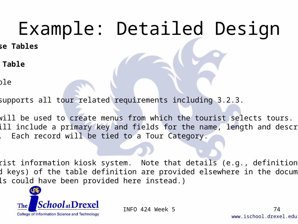
Example: Detailed Design4.1 Database Tables…4.1.3 Tour TableTypeDatabase TableRequirementThis table supports all tour related requirements including 3.2.3.DescriptionThis table will be used to create menus from which the tourist selects tours. The table will include a primary key and fields for the name, length and description of the tour. Each record will be tied to a Tour Category.
(From a tourist information kiosk system. Note that details (e.g., definition of data elements and keys) of the table definition are provided elsewhere in the document. Those details could have been provided here instead.)
74INFO 424 Week 5

www.ischool.drexel.edu
Diagram Hints
• Do them– Often and early, but particularly for the SDS
• Review the notations– And edit the diagrams as you would text– Be fussy about names and choice of elements
• Annotate– No diagram stands by itself– Provide a caption and discussion
• Integrate!! Consistency is critical!– Diagrams must agree with the rest of the document
75INFO 424 Week 5

www.ischool.drexel.edu
Diagram Hints
• General preference for UML– Fits development platforms being used– Fits job skills with market demand
• …But other diagrams are allowed– DFD, ERD, etc.
• Correct and complete use matters most– Particular diagram choice can vary
76INFO 424 Week 5