wwma specifications and tolerances (s&t) committee 2014 ... · 2014 wwma s&t annual agenda...
TRANSCRIPT

2014 WWMA S&T Annual Agenda
S&T –1
WWMA Specifications and Tolerances (S&T) Committee 2014 Annual Report
Mr. Bob Weidler, Chair
Wyoming
September 14-18, 2014 Portland, OR
300 INTRODUCTION
The Specifications and Tolerances (S&T) Committee (hereinafter referred to as “Committee”) submits its Report to the Western Weights and Measures Association (WWMA). The Report consists of the WWMA Agenda (NCWM Carryover and NEW items) and this Addendum. Page numbers in the tables below refer to pages in this Addendum. Suggested revisions to the handbook are shown in bold face print by striking out information to be deleted and underlining information to be added. Requirements that are proposed to be nonretroactive are printed in bold-faced italics. Presented below is a list of agenda items considered by the WWMA and its recommendations to the NCWM Specifications and Tolerances Committee.

2014 WWMA S&T Annual Agenda
S&T – 2
Subject Series List
Introduction .................................................................................................................................................... 300 Series
NIST Handbook 44 – General Code ............................................................................................................... 310 Series
Scales ....................................................................................................................................................... 320 Series Belt-Conveyor Scale Systems ................................................................................................................. 321 Series Automatic Bulk Weighing Systems ........................................................................................................ 322 Series Weights .................................................................................................................................................... 323 Series Automatic Weighing Systems ................................................................................................................. 324 Series
Liquid-Measuring Devices ...................................................................................................................... 330 Series Vehicle-Tank Meters ............................................................................................................................... 331 Series Liquefied Petroleum Gas and Anhydrous Ammonia Liquid-Measuring Devices ................................... 332 Series Hydrocarbon Gas Vapor-Measuring Devices .......................................................................................... 333 Series Cryogenic Liquid-Measuring Devices ..................................................................................................... 334 Series Milk Meters ............................................................................................................................................. 335 Series Water Meters ........................................................................................................................................... 336 Series Mass Flow Meters ................................................................................................................................... 337 Series Carbon Dioxide Liquid-Measuring Devices ............................................................................................ 338 Series Hydrogen Gas-Metering Devices – Tentative Code ................................................................................ 339 Series
Vehicle Tanks Used as Measures ............................................................................................................ 340 Series Liquid Measures ...................................................................................................................................... 341 Series Farm Milk Tanks ..................................................................................................................................... 342 Series Measure-Containers ................................................................................................................................. 343 Series Graduates ................................................................................................................................................. 344 Series Dry Measures .......................................................................................................................................... 345 Series Berry Baskets and Boxes ......................................................................................................................... 346 Series
Fabric-Measuring Devices ....................................................................................................................... 350 Series Wire-and Cordage-Measuring Devices ................................................................................................... 351 Series Linear Measures ...................................................................................................................................... 352 Series Odometers ............................................................................................................................................... 353 Series Taximeters ............................................................................................................................................... 354 Series Timing Devices ....................................................................................................................................... 355 Series Grain Moisture Meters ............................................................................................................................ 356 Series Near-Infrared Grain Analyzers ................................................................................................................ 357 Series Multiple Dimension Measuring Devices ................................................................................................. 358 Series Electronic Livestock, Meat, and Poultry Evaluation Systems and/or Devices – Tentative Code ............ 359 Series
Other Items – Developing Items ..................................................................................................................... 360 Series
2014 WWMA S&T Annual Agenda
S&T –3
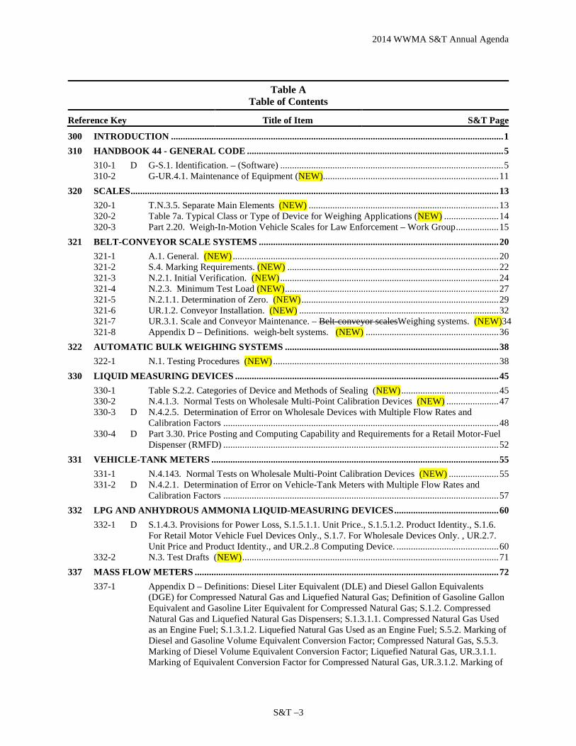
Table A Table of Contents
Reference Key Title of Item S&T Page
300 INTRODUCTION ............................................................................................................................................ 1 310 HANDBOOK 44 - GENERAL CODE ............................................................................................................ 5
310-1 D G-S.1. Identification. – (Software) .............................................................................................. 5 310-2 G-UR.4.1. Maintenance of Equipment (NEW).......................................................................... 11
320 SCALES ........................................................................................................................................................... 13 320-1 T.N.3.5. Separate Main Elements (NEW) ................................................................................ 13 320-2 Table 7a. Typical Class or Type of Device for Weighing Applications (NEW) ....................... 14 320-3 Part 2.20. Weigh-In-Motion Vehicle Scales for Law Enforcement – Work Group .................. 15
321 BELT-CONVEYOR SCALE SYSTEMS ..................................................................................................... 20 321-1 A.1. General. (NEW) ................................................................................................................ 20 321-2 S.4. Marking Requirements. (NEW) ......................................................................................... 22 321-3 N.2.1. Initial Verification. (NEW) ............................................................................................ 24 321-4 N.2.3. Minimum Test Load (NEW) .......................................................................................... 27 321-5 N.2.1.1. Determination of Zero. (NEW) ................................................................................... 29 321-6 UR.1.2. Conveyor Installation. (NEW) .................................................................................... 32 321-7 UR.3.1. Scale and Conveyor Maintenance. – Belt-conveyor scalesWeighing systems. (NEW)34 321-8 Appendix D – Definitions. weigh-belt systems. (NEW) ........................................................ 36
322 AUTOMATIC BULK WEIGHING SYSTEMS .......................................................................................... 38 322-1 N.1. Testing Procedures (NEW) ............................................................................................... 38
330 LIQUID MEASURING DEVICES ............................................................................................................... 45 330-1 Table S.2.2. Categories of Device and Methods of Sealing (NEW) ......................................... 45 330-2 N.4.1.3. Normal Tests on Wholesale Multi-Point Calibration Devices (NEW) ...................... 47 330-3 D N.4.2.5. Determination of Error on Wholesale Devices with Multiple Flow Rates and
Calibration Factors .................................................................................................................... 48 330-4 D Part 3.30. Price Posting and Computing Capability and Requirements for a Retail Motor-Fuel
Dispenser (RMFD) .................................................................................................................... 52 331 VEHICLE-TANK METERS ......................................................................................................................... 55
331-1 N.4.143. Normal Tests on Wholesale Multi-Point Calibration Devices (NEW) ..................... 55 331-2 D N.4.2.1. Determination of Error on Vehicle-Tank Meters with Multiple Flow Rates and
Calibration Factors .................................................................................................................... 57 332 LPG AND ANHYDROUS AMMONIA LIQUID-MEASURING DEVICES ............................................ 60
332-1 D S.1.4.3. Provisions for Power Loss, S.1.5.1.1. Unit Price., S.1.5.1.2. Product Identity., S.1.6. For Retail Motor Vehicle Fuel Devices Only., S.1.7. For Wholesale Devices Only. , UR.2.7. Unit Price and Product Identity., and UR.2..8 Computing Device. ........................................... 60
332-2 N.3. Test Drafts (NEW) ............................................................................................................ 71 337 MASS FLOW METERS ................................................................................................................................ 72
337-1 Appendix D – Definitions: Diesel Liter Equivalent (DLE) and Diesel Gallon Equivalents (DGE) for Compressed Natural Gas and Liquefied Natural Gas; Definition of Gasoline Gallon Equivalent and Gasoline Liter Equivalent for Compressed Natural Gas; S.1.2. Compressed Natural Gas and Liquefied Natural Gas Dispensers; S.1.3.1.1. Compressed Natural Gas Used as an Engine Fuel; S.1.3.1.2. Liquefied Natural Gas Used as an Engine Fuel; S.5.2. Marking of Diesel and Gasoline Volume Equivalent Conversion Factor; Compressed Natural Gas, S.5.3. Marking of Diesel Volume Equivalent Conversion Factor; Liquefied Natural Gas, UR.3.1.1. Marking of Equivalent Conversion Factor for Compressed Natural Gas, UR.3.1.2. Marking of
2014 WWMA S&T Annual Agenda
S&T – 4
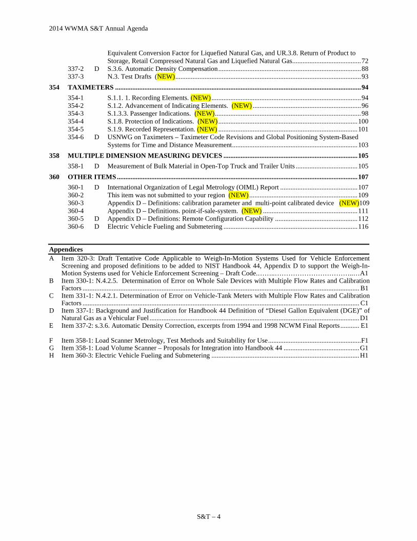
Equivalent Conversion Factor for Liquefied Natural Gas, and UR.3.8. Return of Product to Storage, Retail Compressed Natural Gas and Liquefied Natural Gas ........................................ 72
337-2 D S.3.6. Automatic Density Compensation ................................................................................... 88 337-3 N.3. Test Drafts (NEW) ............................................................................................................ 93
354 TAXIMETERS ............................................................................................................................................... 94 354-1 S.1.1. 1. Recording Elements. (NEW) ....................................................................................... 94 354-2 S.1.2. Advancement of Indicating Elements. (NEW) ............................................................... 96 354-3 S.1.3.3. Passenger Indications. (NEW) ..................................................................................... 98 354-4 S.1.8. Protection of Indications. (NEW) ................................................................................. 100 354-5 S.1.9. Recorded Representation. (NEW) ................................................................................. 101 354-6 D USNWG on Taximeters – Taximeter Code Revisions and Global Positioning System-Based
Systems for Time and Distance Measurement ......................................................................... 103 358 MULTIPLE DIMENSION MEASURING DEVICES .............................................................................. 105
358-1 D Measurement of Bulk Material in Open-Top Truck and Trailer Units .................................... 105 360 OTHER ITEMS ............................................................................................................................................ 107
360-1 D International Organization of Legal Metrology (OIML) Report ............................................. 107 360-2 This item was not submitted to your region (NEW) ............................................................... 109 360-3 Appendix D – Definitions: calibration parameter and multi-point calibrated device (NEW)109 360-4 Appendix D – Definitions. point-if-sale-system. (NEW) ....................................................... 111 360-5 D Appendix D – Definitions: Remote Configuration Capability ................................................ 112 360-6 D Electric Vehicle Fueling and Submetering .............................................................................. 116
Appendices A Item 320-3: Draft Tentative Code Applicable to Weigh-In-Motion Systems Used for Vehicle Enforcement
Screening and proposed definitions to be added to NIST Handbook 44, Appendix D to support the Weigh-In-Motion Systems used for Vehicle Enforcement Screening – Draft Code.……..……………………………..…A1
B Item 330-1: N.4.2.5. Determination of Error on Whole Sale Devices with Multiple Flow Rates and Calibration Factors ................................................................................................................................................................. B1
C Item 331-1: N.4.2.1. Determination of Error on Vehicle-Tank Meters with Multiple Flow Rates and Calibration Factors ................................................................................................................................................................. C1
D Item 337-1: Background and Justification for Handbook 44 Definition of “Diesel Gallon Equivalent (DGE)” of Natural Gas as a Vehicular Fuel .......................................................................................................................... D1
E Item 337-2: s.3.6. Automatic Density Correction, excerpts from 1994 and 1998 NCWM Final Reports ........... E1 F Item 358-1: Load Scanner Metrology, Test Methods and Suitability for Use ...................................................... F1 G Item 358-1: Load Volume Scanner – Proposals for Integration into Handbook 44 ............................................ G1 H Item 360-3: Electric Vehicle Fueling and Submetering ...................................................................................... H1
2014 WWMA S&T Annual Agenda
S&T –5
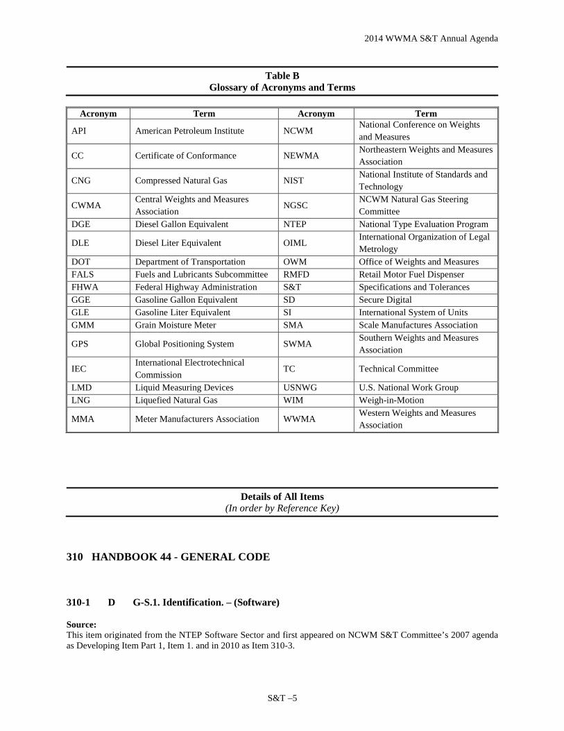
Table B Glossary of Acronyms and Terms
Acronym Term Acronym Term
API American Petroleum Institute NCWM National Conference on Weights and Measures
CC Certificate of Conformance NEWMA Northeastern Weights and Measures Association
CNG Compressed Natural Gas NIST National Institute of Standards and Technology
CWMA Central Weights and Measures Association
NGSC NCWM Natural Gas Steering Committee
DGE Diesel Gallon Equivalent NTEP National Type Evaluation Program
DLE Diesel Liter Equivalent OIML International Organization of Legal Metrology
DOT Department of Transportation OWM Office of Weights and Measures FALS Fuels and Lubricants Subcommittee RMFD Retail Motor Fuel Dispenser FHWA Federal Highway Administration S&T Specifications and Tolerances GGE Gasoline Gallon Equivalent SD Secure Digital GLE Gasoline Liter Equivalent SI International System of Units GMM Grain Moisture Meter SMA Scale Manufactures Association
GPS Global Positioning System SWMA Southern Weights and Measures Association
IEC International Electrotechnical Commission
TC Technical Committee
LMD Liquid Measuring Devices USNWG U.S. National Work Group LNG Liquefied Natural Gas WIM Weigh-in-Motion
MMA Meter Manufacturers Association WWMA Western Weights and Measures Association
Details of All Items
(In order by Reference Key)
310 HANDBOOK 44 - GENERAL CODE
310-1 D G-S.1. Identification. – (Software)
Source: This item originated from the NTEP Software Sector and first appeared on NCWM S&T Committee’s 2007 agenda as Developing Item Part 1, Item 1. and in 2010 as Item 310-3.

2014 WWMA S&T Annual Agenda
S&T – 6
Purpose: Provide marking requirements that enable field verification of the appropriate version or revision for metrological software, including methods other than “permanently marked,” for providing the required information.
Item Under Consideration: Amend NIST Handbook 44: G-S.1. Identification and G-S.1.1. Location of Marking Information for Not-Built-For-Purpose, Software-Based Devices as follows:
G-S.1. Identification. – All equipment, except weights and separate parts necessary to the measurement process but not having any metrological effect, shall be clearly and permanently marked for the purposes of identification with the following information:
(a) the name, initials, or trademark of the manufacturer or distributor;
(b) a model identifier that positively identifies the pattern or design of the device;
(1) The model identifier shall be prefaced by the word “Model,” “Type,” or “Pattern.” These terms may be followed by the word “Number” or an abbreviation of that word. The abbreviation for the word “Number” shall, as a minimum, begin with the letter “N” (e.g., No or No.). The abbreviation for the word “Model” shall be “Mod” or “Mod.” Prefix lettering may be initial capitals, all capitals, or all lowercase.
[Nonretroactive as of January 1, 2003] (Added 2000) (Amended 2001)
(c) a nonrepetitive serial number, except for equipment with no moving or electronic component parts and not-built-for-purpose software-based software devices software; [Nonretroactive as of January 1, 1968] (Amended 2003)
(1) The serial number shall be prefaced by words, an abbreviation, or a symbol, that clearly identifies the number as the required serial number.
[Nonretroactive as of January 1, 1986]
(2) Abbreviations for the word “Serial” shall, as a minimum, begin with the letter “S,” and abbreviations for the word “Number” shall, as a minimum, begin with the letter “N” (e.g., S/N, SN, Ser. No., and S. No.).
[Nonretroactive as of January 1, 2001]
(d) the current software version or revision identifier for not-built-for-purpose software-based electronic devices, which shall be directly linked to the software itself; [Nonretroactive as of January 1, 2004] (Added 2003) (Amended 20XX)
(1) The version or revision identifier shall be prefaced by words, an abbreviation, or a symbol, that clearly identifies the number as the required version or revision. [Nonretroactive as of January 1, 2007] (Added 2006)
(2) Abbreviations for the word “Version” shall, as a minimum, begin with the letter “V” and may be followed by the word “Number.” Abbreviations for the word “Revision” shall, as a minimum, begin with the letter “R” and may be followed by the word “Number.” The abbreviation for the word “Number” shall, as a minimum, begin with the letter “N” (e.g., No or No.). [Nonretroactive as of January 1, 2007] (Added 2006)
(3) The version or revision identifier shall be accessible via the display. Instructions for displaying the version or revision identifier shall be described in the CC. As an exception, permanently marking the version or revision identifier shall be acceptable under the following conditions:
2014 WWMA S&T Annual Agenda
S&T –7
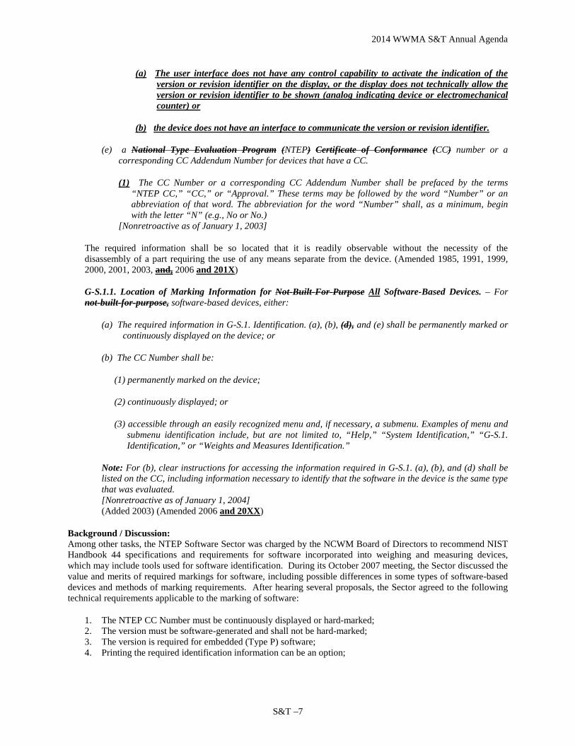
(a) The user interface does not have any control capability to activate the indication of the version or revision identifier on the display, or the display does not technically allow the version or revision identifier to be shown (analog indicating device or electromechanical counter) or
(b) the device does not have an interface to communicate the version or revision identifier.
(e) a National Type Evaluation Program (NTEP) Certificate of Conformance (CC) number or a corresponding CC Addendum Number for devices that have a CC.
(1) The CC Number or a corresponding CC Addendum Number shall be prefaced by the terms “NTEP CC,” “CC,” or “Approval.” These terms may be followed by the word “Number” or an abbreviation of that word. The abbreviation for the word “Number” shall, as a minimum, begin with the letter “N” (e.g., No or No.)
[Nonretroactive as of January 1, 2003]
The required information shall be so located that it is readily observable without the necessity of the disassembly of a part requiring the use of any means separate from the device. (Amended 1985, 1991, 1999, 2000, 2001, 2003, and, 2006 and 201X)
G-S.1.1. Location of Marking Information for Not-Built-For-Purpose All Software-Based Devices. – For not-built-for-purpose, software-based devices, either:
(a) The required information in G-S.1. Identification. (a), (b), (d), and (e) shall be permanently marked or continuously displayed on the device; or
(b) The CC Number shall be:
(1) permanently marked on the device;
(2) continuously displayed; or
(3) accessible through an easily recognized menu and, if necessary, a submenu. Examples of menu and submenu identification include, but are not limited to, “Help,” “System Identification,” “G-S.1. Identification,” or “Weights and Measures Identification.”
Note: For (b), clear instructions for accessing the information required in G-S.1. (a), (b), and (d) shall be listed on the CC, including information necessary to identify that the software in the device is the same type that was evaluated. [Nonretroactive as of January 1, 2004] (Added 2003) (Amended 2006 and 20XX)
Background / Discussion: Among other tasks, the NTEP Software Sector was charged by the NCWM Board of Directors to recommend NIST Handbook 44 specifications and requirements for software incorporated into weighing and measuring devices, which may include tools used for software identification. During its October 2007 meeting, the Sector discussed the value and merits of required markings for software, including possible differences in some types of software-based devices and methods of marking requirements. After hearing several proposals, the Sector agreed to the following technical requirements applicable to the marking of software:
1. The NTEP CC Number must be continuously displayed or hard-marked; 2. The version must be software-generated and shall not be hard-marked; 3. The version is required for embedded (Type P) software; 4. Printing the required identification information can be an option;

2014 WWMA S&T Annual Agenda
S&T – 8
5. Command or operator action can be considered as an option in lieu of a continuous display of the required information; and
6. Devices with Type P (embedded) software must display or hard-mark the device make, model, and serial number to comply with G S.1. Identification.
In 2008, the Software Sector developed and submitted a proposal to the NCWM S&T Committee to modify G-S.1. and associated paragraphs to reflect these technical requirements. Between 2008 and 2011, this item appeared on the S&T Committee’s main agenda and the Committee and the Sector received numerous comments and suggestions relative to the proposal. The Sector developed and presented several alternatives based on feedback from weights and measures officials and manufacturers. Among the key points and concerns raised during discussions over this period were how to address the following:
(a) Limited Character Sets and Space. – How to address devices that have limited character sets or restricted space for marking.
(b) Built-for-Purpose vs. Not-Built-for-Purpose. - Whether or not these should be treated differently.
(c) Ease of Access. – Ease of accessing marking information in the field. • Complexity of locating the marking information • Use of menus for accessing the marking information electronically • Limits on the number of levels required to access information electronically • Possibility of single, uniform method of access
(d) Hard Marking vs. Electronic. – Whether or not some information should be required to be hard marked on the device.
(e) Continuous Display. – Whether or not required markings must be continuously displayed.
(f) Abbreviations and Icons. – Establishment of unique abbreviations, identifiers, and icons and how to codify those.
(g) Certificate of Conformance Information. – How to facilitate correlation of software version information to a CC, including the use of possible icons.
Further details on the alternatives considered can be found in the Committee’s Final Reports from 2008 to 2012.
2013 NCWM Interim Meeting: No comments were received relative to this item during the Open Hearings. In considering the item, the S&T Committee questioned whether or not the Software Sector was still actively working the item. It was reported that the Software Sector believed they had developed the item as much as possible, yet the different stakeholders affected by the proposal could not agree on the changes that the Sector had proposed. Based upon that update, the Committee agreed to add to its report a request that the Software Sector work with the Weighing Sector and Measuring Sector to identify which portions of the proposal need to be modified in order that they might be accepted by the entire community. The Committee acknowledged the efforts of the Software Sector and stated that it looked forward to being able to consider a proposal that addresses both the identification of software and how it may be accessed. Just prior to the 2013 NCWM Annual Meeting, the Software Sector forwarded a modified version of the proposed changes to paragraph G-S.1., which the Sector agreed to during its March 2013 meeting. The modified language, which is now included in Item Under Consideration, includes slight modifications to the previous proposal in an effort to address concerns received from other sectors and interested parties.
With regard to the revised proposal, the Sector reported the following: • That the new language in G-S.1.1 reflects the Sector’s consensus on the following positions:
o The software version/revision should, with very few exceptions, be accessible via the user interface.

2014 WWMA S&T Annual Agenda
S&T –9
o The means by which the software version is accessed must be described in the Certificate of Conformance (CC).
• After removing the “and inseparably” terminology from the proposal, the concerns on the possibility of controversy were reduced.
• The Sector’s opinion on the interpretation of “directly linked” is that it means you can’t change the version/revision without changing the software.
• It may be desirable to evaluate options that would lead to fully eliminating G-S.1.1. The Sector recognized that that this would be a more invasive modification to the existing Handbook and perhaps should be delayed until the first step of addressing software in all devices (not just standalone) was accomplished.
In comments provided to the Committee, the Software Sector indicated that they considered the item sufficiently developed. The Sector noted that since the 2012 meeting, it had tried to promote this item using several means to attempt to address the concerns of other interested parties. For example, a presentation was generated and shared with the SMA at its 2012 meeting. Additionally, most of the regional weights and measures associations had access to this information prior to their meetings, since the proposal was posted on the NCWM website. Unfortunately, based on the comments from the fall 2012 regional association meetings, some regional associations were not aware that this information had been made available. The Sector also noted that they may want to consider more direct methods for sharng information with other groups, such as designating a representative to address the regional groups or other sectors at their meetings. An additional option would be to provide a presentation at the the NCWM Annual Meeting. At the 2013 NCWM Annual Meeting a state director suggested that consideration be given to changing the status of the item to informational. In considering this suggestion, the Committee agreed that the change might be appropriate; however, decided instead to seek input from the NTEP Sectors and industry associations before making that decision. Consequently, the Committee requested that the sectors and industry associations review the Software Sector’s latest proposal at their next meetings. (See the Committee’s 2013 Final Report for details.) At the 2014 NCWM Interim Meeting the SMA commented that it continues to support the work of the Software Sector and encourages communications with the other device sectors. NIST OWM raised two concerns relating to the most recent changes proposed by the Software Sector to subparagraph G-S.1. (d) and offered some suggestions relative to those concerns as follows:
1. Deleting the words “for not-built-for-purpose software-based electronic devices” creates the implication that all equipment manufactured as of January 1, 2004, except weights and separate parts necessary to the measurement process but not having any metrological effect, would be required to be permanently marked with a current software version or revision identifier. OWM questioned whether or not it was the Software Sector’s intent to require a software version or revision identifier be marked on equipment that is not electronic. If not the intent, OWM suggested that the Sector consider adding additional text to better clarify the type of equipment intended to be addressed by this proposed change and offered the following additional text for consideration:
(d) the current software version or revision identifier for software-based electronic devices, which shall be directly linked to the software itself;
2. The proposed changes would require a current software version or revision identifier be marked on both
built-for-purpose and not-built-for purpose software based equipment manufactured as of January 1, 2004. If it is the intent of the Sector to require that a current software version or revision identifier be marked on built-for-purpose software based equipment, then the Sector might consider proposing that such a requirement be non-retroactive considering the time and cost involved in updating equipment already in service.
OWM also provided the following additional feedback on the Software Sector’s proposed changes to paragraphs G-S.1. and G-S.1.1.:

2014 WWMA S&T Annual Agenda
S&T – 10
• It is not clear what equipment would be affected by the proposed changes to G-S.1. (c). By proposing that the word “software” be added, is the exception intended to apply to the software itself or to equipment in which the software is installed?
• In the proposed additions to G-S.1. (d)(3)(a), it is not clear what is meant by the phrase “or the display does not technically allow the version or revision identifier to be shown.” The examples “analog indicating device” and “electromechanical counter” are confusing. OWM doesn’t believe these examples provide enough information to lead one to conclude that the intent is to address such things as numeric-only displays. For example, numeric-only displays that don’t have the capability of displaying abbreviations for “version” or “revision” as noted in earlier comments originating from the Sector.
• OWM recommends adding some examples to clarify the types of devices described in paragraph G-S.1. (d)(3)(b).
• OWM agrees with the Software Sector’s assertion that it may be possible to eventually eliminate G-S.1.1. at some future date.
The Committee is concerned that this item has remained on S&T’s agenda for a long time with little progress. The Committee appreciates the efforts of the Software Sector and recognizes the difficulty in developing a proposal that meets the needs of multiple groups. The Committee agreed to maintain the item on its agenda to allow the Sector to finalize work on this issue; however, if no progress is made in the next year, the Committee plans to withdraw the item from its agenda. The Committee notes that this would not preclude the Sector from resubmitting the item at some point in the future when additional work has been done or the item has been fully developed. At the 2014 NCWM Annual Meeting Mr. Steve Langford (Cardinal Scale) speaking on behalf of the Scale Manufacturers Association, indicating that the SMA supports this item. Juana Williams, NIST OWM, suggested that a joint meeting of all Sectors might assist in developing a proposal that meets the needs of multiple segments of the community. The Committee reiterates its intent to withdraw this item at the 2015 Interim Meeting if progress has not been made.
NTEP Sector Meeting Comments: 2013 NTEP Weighing Sector Meeting (August 2013): The Weighing Sector reviewed the March 2013 proposal from the Software Sector. There were no comments except that one Sector member questioned whether or not a nonrepetitive serial number is needed for software. The example provided was two software applications running on a single PC that was interfaced with two weighing elements. In this example, how would an inspector know which weighing system he/she is evaluating? The Sector discussed this concern and agreed to forward it to the Software Sector and the S&T Committee for consideration. 2013 Grain Analyzer Sector (August 2013) and NTEP Measuring Sector (October 2013): The Grain Analyzer Sector and the Measuring Sector did not consider the Software Sector’s most recent draft update to amend G-S.1. and G-S.1.1. during their meetings. Regional Association Comments: WWMA agrees this item has merit, but it needs further development. The WWMA recognized the importance of this item at their 2011 and 2012 Regional meetings but agreed further development is needed by the Software Sector. The WWMA also acknowledged that three regions recommended the item remain Developing. WWMA looks forward to hearing the results of the Weighing and Software Sector’s joint meeting and recommended that this item remain as a Developing Item.
SWMA received a presentation by Mr. Doug Bliss (Mettler Toledo) on behalf of the Software Sector. The Committee considered recommending this as a Voting Item due to the length of time it has been on the agenda, but comments received indicated that progress would be made in the next year and, with this information, the Committee recommends it be maintained as a Developing Item. NEWMA heard no opposition to the continued development of this item. CWMA supported this item as a Developing Item.
2014 WWMA S&T Annual Agenda
S&T –11
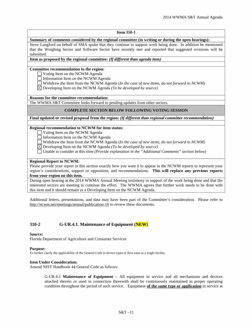
Item 310-1
Summary of comments considered by the regional committee (in writing or during the open hearings): Steve Langford on behalf of SMA spoke that they continue to support work being done. In addition he mentioned that the Weighing Sector and Software Sector have recently met and reported that suggested revisions will be submitted. Item as proposed by the regional committee: (If different than agenda item) Committee recommendation to the region:
Voting Item on the NCWM Agenda Information Item on the NCWM Agenda Withdraw the Item from the NCWM Agenda (In the case of new items, do not forward to NCWM) Developing Item on the NCWM Agenda (To be developed by source)
Reasons for the committee recommendation: The WWMA S&T Committee looks forward to pending updates from other sectors.
COMPLETE SECTION BELOW FOLLOWING VOTING SESSION
Final updated or revised proposal from the region: (If different than regional committee recommendation) Regional recommendation to NCWM for item status:
Voting Item on the NCWM Agenda Information Item on the NCWM Agenda Withdraw the Item from the NCWM Agenda (In the case of new items, do not forward to NCWM) Developing Item on the NCWM Agenda (To be developed by source) Unable to consider at this time (Provide explanation in the “Additional Comments” section below)
Regional Report to NCWM: Please provide your report in this section exactly how you want it to appear in the NCWM reports to represent your region’s considerations, support or opposition, and recommendations. This will replace any previous reports from your region on this item. During open hearing at the 2014 WWMA Annual Meeting testimony in support of the work being done and that the interested sectors are meeting to continue the effort. The WWMA agrees that further work needs to be done with this item and it should remain as a Developing Item on the NCWM Agenda. Additional letters, presentations, and data may have been part of the Committee’s consideration. Please refer to http://ncwm.net/meetings/annual/publication-16 to review these documents.
310-2 G-UR.4.1. Maintenance of Equipment (NEW)
Source: Florida Department of Agriculture and Consumer Services
Purpose: To further clarify the applicability of the General Code to device types or flow rates at a single facility.
Item Under Consideration: Amend NIST Handbook 44 General Code as follows:
G-UR.4.1 Maintenance of Equipment – All equipment in service and all mechanisms and devices attached thereto or used in connection therewith shall be continuously maintained in proper operating condition throughout the period of such service. Equipment of the same type or application in service at

2014 WWMA S&T Annual Agenda
S&T – 12
a single place of business found to be in error predominantly in a direction favorable to the device user (see also Introduction, Section Q) shall not be considered “maintained in a proper operating condition.”
Background / Discussion: It is not uncommon for a single place of business to have in use different types of devices (or meters with different flow rates) at the same time. A truck stop may have retail meters for passenger vehicles and high-volume meters for commercial vehicles, both having different tolerances and essentially operating as separate sections at a single place of business. As this section is currently written, it would include both of these meters types under ‘equipment’ and thus apply ‘predominantly in favor’ across all meters, despite the fact that one group of these meters could be predominantly in favor of the vendor while the other is not, thus leaving the weights and measures official without the ability to correct such a situation under the general code. Similar situations may exist with scales and other measuring devices. Further clarifying ‘equipment’ to apply to the same type or application use in this section would alleviate that potential.
Item 31-2
Summary of comments considered by the regional committee (in writing or during the open hearings): Steve Cook, CA, stated that he understood the reason for the proposal but feels there may be multiple interpretations resulting in confusion. Kurt Floren, LA County, stated that he agreed with the ambiguity and feels that the intent is toward LMD’s. However, this is in the General Code and may cause problems with other devices. Item as proposed by the regional committee: (If different than agenda item) Committee recommendation to the region:
Voting Item on the NCWM Agenda Information Item on the NCWM Agenda Withdraw the Item from the NCWM Agenda (In the case of new items, do not forward to NCWM) Developing Item on the NCWM Agenda (To be developed by source)
Reasons for the committee recommendation: The WWMA S&T Committee does not believe this will clarify the intended purpose of the proposal. Further, we believe that it may cause confusion with regard to other types of devices.
COMPLETE SECTION BELOW FOLLOWING VOTING SESSION
Final updated or revised proposal from the region: (If different than regional committee recommendation) Regional recommendation to NCWM for item status:
Voting Item on the NCWM Agenda Information Item on the NCWM Agenda Withdraw the Item from the NCWM Agenda (In the case of new items, do not forward to NCWM) Developing Item on the NCWM Agenda (To be developed by source) Unable to consider at this time (Provide explanation in the “Additional Comments” section below)
Regional Report to NCWM: Please provide your report in this section exactly how you want it to appear in the NCWM reports to represent your region’s considerations, support or opposition, and recommendations. This will replace any previous reports from your region on this item. At the 2014 WWMA Annual Meeting opposition to this item was expressed during open hearings. Several regulators spoke to the potential for multiple interpretations/confusion and felt the intent of the proposal was geared toward liquid measuring devices in spite of it being located in the General Code section. The WWMA voted to withdraw this item based on testimony given.

2014 WWMA S&T Annual Agenda
S&T –13
320 SCALES
320-1 T.N.3.5. Separate Main Elements (NEW)
Source: Ohio NTEP Laboratory
Purpose: Improve uniformity in how the tolerance is applied by providing clarification of the intent.
Item Under Consideration: Amend NIST Handbook 44 Scales Code as follows:
T.N.3.5. Separate Main Elements: Load Transmitting Element, Indicating Element, Etc. – If a main element separate from a complete weighing device is submitted for laboratory type evaluation, the tolerance for the main element is 0.7 that for the complete weighing device. This fraction includes the tolerance attributable to the testing devices used.
Background / Discussion: The submitter wants to distinguish the difference between laboratory testing, and field testing to eliminate any confusion as to what tolerance to apply. The word “laboratory” is not implied in the current wording. As worded, there are differences in opinions as to the intent on this paragraph. This proposal would improve uniformity in all NTEP evaluations. The Ohio NTEP Laboratory has held field evaluations to 0.7 tolerance in the past.
Item 31-2
Summary of comments considered by the regional committee (in writing or during the open hearings): Steve Cook, CA, stated that he understood the reason for the proposal but feels there may be multiple interpretations resulting in confusion. Kurt Floren, LA County, stated that he agreed with the ambiguity and feels that the intent is toward LMD’s. However, this is in the General Code and may cause problems with other devices. Item as proposed by the regional committee: (If different than agenda item) Committee recommendation to the region:
Voting Item on the NCWM Agenda Information Item on the NCWM Agenda Withdraw the Item from the NCWM Agenda (In the case of new items, do not forward to NCWM) Developing Item on the NCWM Agenda (To be developed by source)
Reasons for the committee recommendation: The WWMA S&T Committee does not believe this will clarify the intended purpose of the proposal. Further, we believe that it may cause confusion with regard to other types of devices.
COMPLETE SECTION BELOW FOLLOWING VOTING SESSION
Final updated or revised proposal from the region: (If different than regional committee recommendation) Regional recommendation to NCWM for item status:
Voting Item on the NCWM Agenda Information Item on the NCWM Agenda Withdraw the Item from the NCWM Agenda (In the case of new items, do not forward to NCWM) Developing Item on the NCWM Agenda (To be developed by source) Unable to consider at this time (Provide explanation in the “Additional Comments” section below)
Regional Report to NCWM:

2014 WWMA S&T Annual Agenda
S&T – 14
Please provide your report in this section exactly how you want it to appear in the NCWM reports to represent your region’s considerations, support or opposition, and recommendations. This will replace any previous reports from your region on this item. At the 2014 WWMA Annual Meeting opposition to this item was expressed during open hearings. Several regulators spoke to the potential for multiple interpretations/confusion and felt the intent of the proposal was geared toward liquid measuring devices in spite of it being located in the General Code section. The WWMA voted to withdraw this item based on testimony given.
320-2 Table 7a. Typical Class or Type of Device for Weighing Applications (NEW)
Source: Ohio NTEP Laboratory
Purpose: Require that hopper scales less than 2000 lb., which are not grain hoppers, be class III devices and allow “special devices” greater than 30 000 lb that are not vehicle scales and not currently listed under Class III L, to be categorized as Class III L.
Item Under Consideration: Amend NIST Handbook 44 Scale Code as follows:
Table 7a. Typical Class or Type of Device for Weighing Applications
Class Weighing Application or Scale Type
I Precision laboratory weighing
II Laboratory weighing, precious metals and gem weighing, grain test scales
III
All commercial weighing not otherwise specified, grain test scales, retail precious metals and semi-precious gem weighing, grain-hopper scales, other hopper scales under 2,000 lb, animal scales, postal scales, vehicle on-board weighing systems with a capacity less than or equal to 30 000 lb, and scales used to determine laundry charges
III L Vehicle scales, vehicle on-board weighing systems and other special devices with a capacity greater than 30 000 lb, axle-load scales, livestock scales, railway track scales, crane scales, and hopper (other than grain hopper) scales
IIII Wheel-load weighers and portable axle-load weighers used for highway weight enforcement
Note: A scale with a higher accuracy class than that specified as “typical” may be used.
(Amended 1985, 1986, 1987, 1988, 1992, 1995, and 2012) Background / Discussion: Many small hoppers that are not grain hoppers are already receiving CC’s as Class III hoppers, which does not meet Table 7a categories. There are also a few large capacity floor scales that have to meet Class III tolerances that really don’t need that level of accuracy and would benefit from being categorized as a Class III L device.
Item 320-2
Summary of comments considered by the regional committee (in writing or during the open hearings): No comments were received during open hearings. Item as proposed by the regional committee: (If different than agenda item)
2014 WWMA S&T Annual Agenda
S&T –15
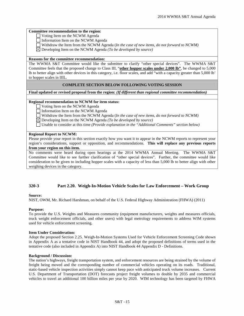
Committee recommendation to the region: Voting Item on the NCWM Agenda Information Item on the NCWM Agenda Withdraw the Item from the NCWM Agenda (In the case of new items, do not forward to NCWM) Developing Item on the NCWM Agenda (To be developed by source)
Reasons for the committee recommendation: The WWMA S&T Committee would like the submitter to clarify “other special devices”. The WWMA S&T Committee feels that the proposed change to Class III, “other hopper scales under 2,000 lb”, be changed to 5,000 lb to better align with other devices in this category, i.e. floor scales, and add “with a capacity greater than 5,000 lb’ to hopper scales in IIIL.
COMPLETE SECTION BELOW FOLLOWING VOTING SESSION
Final updated or revised proposal from the region: (If different than regional committee recommendation) Regional recommendation to NCWM for item status:
Voting Item on the NCWM Agenda Information Item on the NCWM Agenda Withdraw the Item from the NCWM Agenda (In the case of new items, do not forward to NCWM) Developing Item on the NCWM Agenda (To be developed by source) Unable to consider at this time (Provide explanation in the “Additional Comments” section below)
Regional Report to NCWM: Please provide your report in this section exactly how you want it to appear in the NCWM reports to represent your region’s considerations, support or opposition, and recommendations. This will replace any previous reports from your region on this item. No comments were heard during open hearings at the 2014 WWMA Annual Meeting. The WWMA S&T Committee would like to see further clarification of “other special devices”. Further, the committee would like consideration to be given to including hopper scales with a capacity of less than 5,000 lb to better align with other weighing devices in the category.
320-3 Part 2.20. Weigh-In-Motion Vehicle Scales for Law Enforcement – Work Group
Source: NIST, OWM, Mr. Richard Harshman, on behalf of the U.S. Federal Highway Administration (FHWA) (2011)
Purpose: To provide the U.S. Weights and Measures community (equipment manufacturers, weights and measures officials, truck weight enforcement officials, and other users) with legal metrology requirements to address WIM systems used for vehicle enforcement screening.
Item Under Consideration: Adopt the proposed Section 2.25. Weigh-In-Motion Systems Used for Vehicle Enforcement Screening Code shown in Appendix A as a tentative code in NIST Handbook 44, and adopt the proposed definitions of terms used in the tentative code (also included in Appendix A) into NIST Handbook 44 Appendix D - Definitions.
Background / Discussion: The nation’s highways, freight transportation system, and enforcement resources are being strained by the volume of freight being moved and the corresponding number of commercial vehicles operating on its roads. Traditional, static-based vehicle inspection activities simply cannot keep pace with anticipated truck volume increases. Current U.S. Department of Transportation (DOT) forecasts project freight volumes to double by 2035 and commercial vehicles to travel an additional 100 billion miles per year by 2020. WIM technology has been targeted by FHWA

2014 WWMA S&T Annual Agenda
S&T – 16
and Federal Motor Carrier Safety Administration as a technology capable of supporting more effective and efficient truck weight enforcement programs.
Several DOT efforts are underway and planned for the future to maintain adequate levels of enforcement that ensure equity in the trucking industry market and protection of highway infrastructure. Judicial support for enforcement decisions to apply more intense enforcement actions on specific trucks depends on support from the U.S. legal metrology community. Standards are needed in NIST Handbook 44 to address the design, installation, accuracy, and use of WIM systems used in a screening/sorting application. The implementation of a uniform set of standards will greatly improve the overall efficiency of the nation’s commercial vehicle enforcement process.
Once adopted by the truck weight enforcement community, these requirements will enhance the accuracy of the nation’s WIM scale systems; serve as a sound basis for judicial support of next-generation truck weight enforcement programs; and result in fewer legally loaded vehicles being delayed at static weigh station locations, thus reducing traffic congestion and non-productive fuel consumption and improving the movement of freight on our nation’s roadways.
Purpose of the Project: The FHWA’s Office of Freight Management and Operations recognized a need to encourage uniformity in the design, testing, installation, and performance of WIM technology and subsequently encourage acceptance by prosecution agencies (administrative or judicial) regarding the validity of WIM technology’s role in supporting commercial motor vehicle weight enforcement.
In response to this need and recognizing the value of having a standard included in NIST Handbook 44 because it lends integrity and is more recognizable in legal actions, the FHWA seeks to integrate WIM technology into the Handbook. The FHWA contracted the services of the Texas Transportation Institute of the Texas A&M University System and Battelle (a private company) to begin this process. Additionally, a small oversight Committee was formed by the FHWA, made up of three representatives from the FHWA, NIST, and a U.S. manufacturer of WIM equipment to validate that each contract deliverable is completed according to contract. NIST OWM also agreed to provide a technical advisor to the associated work group tasked with development of the proposed code.
The intended application of the proposed new code is for screening purposes only (i.e., for screening/sorting commercial vehicles for possible violations of FHWA vehicle weight requirements).
To view a detailed summary on the progress of this project since its inception in December 2011 through 2012, refer to “Timeline of Completed Tasks Relating to the Project” in S&T Agenda Item 360-3 in the Committee’s 2012 Final Report. Additional background information and information on the work is also included in that report.
2013 NCWM Interim Meeting: The Committee agreed to designate the item Informational based on a recommendation from Mr. Darrell Flocken, Chairman of the WIM WG and comments the Committee received in support of the item during its Open Hearings. Mr. Flocken reported that a new Draft WIM Code and a document containing definitions of terms used in the draft Code had been developed by members of the USNWG and were ready for an initial review. Both documents had been posted on the NCWM website and the USNWG was requesting feedback from the W&M community on both parts.
2013 NCWM Annual Meeting: During its Open Hearings, the Committee was provided an update on the development of the draft WIM Code from Mr. Flocken, Chairman of WIM WG. Mr. Flocken also clarified that its scope is strictly for screening purposes. OWM encouraged further development of the draft Code by the Weigh-In-Motion WG and offered the following feedback on the first draft in response to the WG’s request to do so:
1) To ensure that test procedures are applied uniformly, the WG may want to consider including in the draft Code procedures for establishing the reference weights of axle loads, axle-group loads, and gross vehicle weight. The WG may also want to consider specifying the types of scales considered acceptable for use in establishing such test loads and their acceptable degree of accuracy. Currently, Table T.3.1. of the draft Code specifies tolerances for axle load, axle group load, and gross vehicle weight. It also specifies that
2014 WWMA S&T Annual Agenda
S&T –17
these tolerances be based on a percentage of the applied test load. In order to apply these tolerances, test loads of known value for axle load, axle-group load, and gross vehicle weight need to be established in advance of dynamic testing of a WIM system using a reference scale suitable for making such determinations. Additionally, in accordance with NIST Handbook 44 Appendix A – Fundamental Considerations, the combined error and uncertainty of the test loads, if used without correction, must be less than one-third the applicable tolerance. The draft Code does not provide an indication of the types of scales considered acceptable for making such reference weight determinations (e.g. vehicle, axle-load, etc.) or the procedures that are to be followed when using those scales to establish the reference weights. OWM notes that the accuracy of the reference scale used for determining gross vehicle weight seems to be adequately addressed in paragraph N.1.3. Reference Scale, which requires each reference vehicle to be weighed on a static scale meeting NIST Handbook 44 maintenance tolerances.
2) The WG may also want to consider including in the draft Code specific requirements applicable to the design, installation, and maintenance of the approach and exit aprons of the weigh sensor(s) of a WIM system. OWM questions whether or not it’s possible to obtain accurate and repeatable axle-load, axle-group-load, and gross vehicle weight determinations from vehicle WIM systems without including such requirements. Such requirements are needed to filter out inconsistent forces such as the following:
• “Wheel hop” (or bounce) causes undesirable accelerated vertical forces to be applied to the weigh
sensor(s) of a WIM system as vehicles to be weighed in motion pass over them. Such undesirable forces result when the tires of a vehicle to be weighed in motion pass over an irregular pavement surface on either side of the weigh sensor(s).
• “Force transfer” is the transfer of applied force from one part of a vehicle being weighed in motion to another part. Such transfer of forces occur, for example, when individual axles or tandem axles of a vehicle are weighed individually and are not in the same plane (i.e., the vehicle being weighed is not level).
During development of the draft Code, the WIM WG agreed not to include specific requirements for aprons in advance of and beyond the load sensor(s), but rather, agreed to include the following language in paragraph UR.2. User Location Conditions and Maintenance to deal with this issue: “The system shall be installed and maintained as defined in the manufacturer’s recommendation.” While the draft Code does include a user requirement intended to address this issue, the draft language alone is not sufficient enough to adequately address this important aspect of a vehicle WIM installation. Based on expert analysis, OWM understands that minimum requirements for apron smoothness, slope, etc., are needed in order to achieve necessary levels of accuracy. Both ASTM E-1318-09 and OIML R134 include requirements that address the area leading to and from the sensor(s) of a WIM system. For example, the ASTM standard includes requirements for horizontal and longitudinal alignment, cross slope, surface smoothness, etc.
3) OWM suggests that the WIM WG revisit the idea of including in the draft Code additional accuracy classes for WIM’s capable of achieving greater accuracy levels. During the most recent WIM WG meeting, some manufacturers of WIM equipment indicated that their equipment could meet a 6% gross vehicle weight tolerance, which is significantly less than the 10% currently specified in the draft Code. The WG then considered whether to include different accuracy classes and specify corresponding tolerances for those accuracy classes in the draft Code. However, the WG ultimately agreed to a single accuracy class and set of tolerances for the following reasons:
• The WG felt it was more expedient to simply specify a single accuracy class and set the limit of
accuracy for that classification at the lowest end of what it considered an acceptable level of accuracy given the application of the device, and

2014 WWMA S&T Annual Agenda
S&T – 18
• The WG agreed that the tasks performed by a WIM system, whether the WIM system is a “virtual weigh station” or one installed in a ramp at a more permanent site (e.g., a “weigh station” along an interstate highway) are the same.
OWM notes that tiered accuracy classes are already established in both ASTM E 1318-09 and OIML R-134. History has proven that it is better to establish a framework of tolerances around the various performance capabilities of equipment available in the marketplace early on in the development of the Code, rather than designing the Code around systems that provide lowest accuracy and then trying to change the Code later.
In early discussions with representatives from FHWA, it was stated that one of the FHWA’s main goals for developing the draft Code was to improve the accuracy and reliability of WIM systems in order to reduce the number of compliant commercial vehicles (i.e., those within legal load limits) being directed to static scales, which slows the transportation of freight. OWM recognizes the additional work that would be required by the WIM WG if it were to decide to include additional accuracy classes, but by doing so, it would benefit many (including transportation industry and consumers) and improve the chances of the FHWA achieving one of its primary goals.
Mr. Dan Middleton, (Texas A&M University) WIM Project Task Manager, speaking on behalf of the U.S. FHWA, voiced support for the item by stating that the new Code would improve consistency and legal credibility in the courts. He indicated that the U.S. does not have enough resources to adequately enforce highway weight requirements. Use and recognition of WIM standards in NIST Handbook 44 will allow better use of enforcement resources. In providing further evidence of the need for the Code, he noted that currently less than one percent of vehicles directed to a static scale after being sorted on a WIM System are noncompliant.
Mr. Steve Langford (Cardinal Scale Manufacturing Company) commented that Cardinal Scale Manufacturing Company manufactures a series of WIM scales and encouraged further development of the draft Code. He indicated that tiered accuracy classes are not important, nor needed in the Code, at this time. The purpose of the WIM is to identify vehicles for enforcement; this is contrary to the application of OIML R134, which is intended for WIM systems used in trade. ASTM 1318 provides different accuracy classes, only one of which corresponds with the application of the draft Code.
Mr. Tim Chesser (State of Arkansas) recommended a statement be included in the Application Section of the draft Code clarifying that the Code is intended for screening/sorting purposes only. NIST Technical Advisor’s note: It is believed that paragraph A.1. of the draft Code already addresses Mr. Chesser’s concern. Paragraph A.1. General. specifies that the Code applies to systems used to weigh vehicles, while in motion, for the purpose of screening or sorting the vehicles based on vehicle weight to determine if a static weighment is necessary.
Ms. Julie Quinn (State of Minnesota) supported maintaining the “Informational” status of the item and encouraged the WG to move quickly to finalize completion of the draft Code.
Mr. Flocken expressed his appreciation for the comments received and indicated that he would forward them, along with OWM’s feedback, to the WG for consideration. The Committee reported that it was their understanding that Mr. Flocken would share OWM’s suggestions with members of the WIM WG prior to their next meeting and the WG would consider whether or not additional revisions to the draft Code are necessary prior to proposing the Code to the NCWM for adoption.
At the 2014 NCWM Interim Meeting the WIM Project Leader, Mr. Tom Kearney (USDOT - FHWA) provided an update on progress. Mr. Kearney indicated that the WG had planned to convene during the fall of 2013 to address the three concerns raised by OWM during the 2013 NCWM Annual Meeting but was unable to do so because of scheduling conflicts. Since the 2013 NCWM Annual Meeting, a WG member from the Netherlands had submitted

2014 WWMA S&T Annual Agenda
S&T –19
some new comments concerning the draft Code. The purpose of the next WG meeting will be to address the three OWM concerns and to review the new comments that came in from the Netherlands. That WG meeting will likely take place in April or May 2014. It is hoped that revisions to the draft Code can be completed shortly thereafter so that a revised copy of the draft Code can be made available to members of the W&M community prior to the NCWM Annual Meeting in July 2014. In the meantime, the WG continues to seek input on the current draft from anyone wishing to do so. The SMA commented that it continues to support the efforts of the work group and looks forward to seeing the next draft of the proposed Code. Mr. Steve Langford (Cardinal Scale Manufacturing Co.) also voiced his support of the efforts of the WG. The Committee agreed to maintain the Informational status of the item and looks forward to further development of the draft Code by the WG.
At the 2014 NCWM Annual Meeting the NIST Technical Advisor provided a progress report of the FHWA’s Work Group. Mr. Steve Langford (Cardinal Scale) speaking as a member of the Project Oversight Committee, commented in support of the proposal and noted that an updated draft of the WIM code will be submitted to the fall regional associations for consideration.
The Committee plans to include a copy of the most recent draft code in their final report. Copies are also available from the WIM WG Committee Chair Mr. Darrell Flocken (NCWM).
Regional Associations Comments: WWMA recognizes the efforts by the WIM WG and Mr. Flocken’s comments that updated the conference on the progress of the WG. The WWMA looks forward to hearing the results of the WIM WG meeting. WWMA recommended that this item be an Informational Item. SWMA received a Work Group report from Mr. Darrell Flocken. The Committee did not have a recommendation on this item. Based on comments received, the Committee supported further development of the draft Code by the WIM Work Group. NEWMA recognized that work is ongoing on this item and recommends the Informational status be maintained pending the outcome of the WIM WG Meeting. CWMA supported maintaining this item as Informational because there was no progress reported.
Item 320-3
Summary of comments considered by the regional committee (in writing or during the open hearings): Steve Langford, member of the WIM WG, stated that this item is on its third draft and current version is located in Appendix A; the workgroup is scheduled to meet in November 2014 and there may be some changes. Mr. Langford supports the item. Carol Hockert, NIST OWM, echoed Steve’s comments and stated this item is ready to move forward to vote. Item as proposed by the regional committee: (If different than agenda item) Committee recommendation to the region:
Voting Item on the NCWM Agenda Information Item on the NCWM Agenda Withdraw the Item from the NCWM Agenda (In the case of new items, do not forward to NCWM) Developing Item on the NCWM Agenda (To be developed by source)
Reasons for the committee recommendation: The WWMA S&T Committee feels this item is fully developed and ready to move forward for a vote. During Committee discussion it was noted that the proposal does not have provision for approaches onto and off of the weighing element and this may need to be addressed at the 2015 NCWM Interim Meeting.

2014 WWMA S&T Annual Agenda
S&T – 20
COMPLETE SECTION BELOW FOLLOWING VOTING SESSION
Final updated or revised proposal from the region: (If different than regional committee recommendation) Regional recommendation to NCWM for item status:
Voting Item on the NCWM Agenda Information Item on the NCWM Agenda Withdraw the Item from the NCWM Agenda (In the case of new items, do not forward to NCWM) Developing Item on the NCWM Agenda (To be developed by source) Unable to consider at this time (Provide explanation in the “Additional Comments” section below)
Regional Report to NCWM: Please provide your report in this section exactly how you want it to appear in the NCWM reports to represent your region’s considerations, support or opposition, and recommendations. This will replace any previous reports from your region on this item. At the 2014 WWMA Annual Meeting testimony was presented in support of this item moving forward as a Voting Item and several felt that it is sufficiently developed. The WWMA supports this as a Voting Item and looks forward to it being presented on the 2015 NCWM Annual Meeting Agenda. Additional letters, presentations, and data may have been part of the Committee’s consideration. Please refer to http://ncwm.net/meetings/annual/publication-16 to review these documents.
321 BELT-CONVEYOR SCALE SYSTEMS
321-1 A.1. General. (NEW)
Source: U.S. National Work Group on Belt-Conveyor Scales Purpose: Expand the application of the Belt-Conveyor scale Systems Code to include weigh-belt systems to ensure that they are held to proper standards.
Item Under Consideration: Amend NIST Handbook 44 Belt-Conveyor Scale Systems Code as follows:
A.1. General. – This code applies to belt conveyor scale systems and weigh-belt systems used for the weighing of bulk materials
Background / Discussion: The USNWG for Belt-Conveyor Scales has identified gaps in multiple locations within the Handbook 44 Belt-Conveyor Scales Systems Code which would not allow a typical weigh-belt system type of design to be appropriately covered by the requirements found in this code. The USNWG has developed a number of proposals to amend each of these requirements so that weigh-belt systems will be in compliance with them. Paragraph A.1. is the first in this series of proposed changes. This proposed change expressly states that the Handbook 44 Belt-Conveyor Scale Systems Code will also apply to weigh-belt systems.
NIST Handbook 44 Belt-Conveyor Scale Systems Code language that existed prior to 2001 provided an exemption for belt-conveyor scale systems designed and furnished by the manufacturer from requirements that concerned the details of installation of belt-conveyor scale systems. Generally, weigh-belt systems are designed and built by the manufacturer as a unit and are therefore are less likely to be susceptible to malfunctions or operational defects

2014 WWMA S&T Annual Agenda
S&T –21
directly caused by a variance from the manufacturer’s intended installation specifications. This is in contrast to belt-conveyor scale systems that are typically installed as separate components (conveyor, weighing system, belt loading system, speed sensor, etc.) within an existing conveyor system where the details of the installation for each component may greatly influence the performance of other components in the system. That language which has since been deleted is shown below:
UR.2.2.1. For Scales not Installed by the Manufacturer. - Unless the scale is installed in a conveyor designed and furnished by the scale manufacturer or built to the scale manufacturer’s specifications, the conveyor shall comply with the following minimum requirements: …* (Amended 1998)
*The subparagraphs that followed, UR.2.2.1.(a) through (j), consisted of requirements addressing specific criteria related to design and installation of the conveyor system.
The deletion of the statement: “installed in a conveyor designed and furnished by the scale manufacturer or built to the scale manufacturer’s specifications” created a situation where all belt-conveyor scale systems that were covered by the Handbook 44 BCS Code were to meet requirements in that included: specific limitations on the location of conveyor components in relation to the weighing element; specific limits on the length of the conveyor; and the type of take-up device used in the system. Due to the design and construction of typical weigh-belt systems, this type of device was not able to comply with these requirements largely due to the size, placement, and location of components in a weigh-belt type of system and the distances required between those components and the weighing elements.
USNWG members have agreed that it is important not to impose prescriptive requirements that may restrict innovation in the design of this type of device. Requirements that place limitations on the placement of components in a conveyor system in relation to the weighing device and to each other are viewed as being arbitrary and may be invalid if the design of a system is shown to operate within performance requirements regardless of the configuration of its components.
Belt-conveyor scale manufacturers who are members of the USNWG reported a demand from various clients for relatively compact weigh-belt type of systems to be used as a commercial device. However, unless the Handbook 44 BCS Code is amended to allow for their unique design characteristics, there was not an appropriate code in Handbook 44 to apply to weigh-belt systems. The USNWG therefore, has developed a number of proposed changes throughout the existing Belt-Conveyor Scale Systems Code to adapt these requirements so that they may be applied to weigh-belt systems as well.
Item 321-1
Summary of comments considered by the regional committee (in writing or during the open hearings): Peter Sirrico, Thayer Scale, commented that this item has been in development for 3 years and supports moving it to voting status. He further commented that prior to 2001, these types of devices were recognized in Handbook 44. Steve Cook, CA, supports the item and states that several have been approved in California. Item as proposed by the regional committee: (If different than agenda item) Committee recommendation to the region:
Voting Item on the NCWM Agenda Information Item on the NCWM Agenda Withdraw the Item from the NCWM Agenda (In the case of new items, do not forward to NCWM) Developing Item on the NCWM Agenda (To be developed by source)
Reasons for the committee recommendation: The WWMA S&T Committee acknowledges and appreciates the work and advice of the USNWG on Belt Conveyor Scales. The WWMA S&T Committee feels this item is fully developed and ready to move forward for a vote. The Committee recommends that items 321-1, 321-2, 321-3, 321-4, 321-5, 321-6, 321-7 and 321-8 be combined in to one proposal.
COMPLETE SECTION BELOW FOLLOWING VOTING SESSION

2014 WWMA S&T Annual Agenda
S&T – 22
Final updated or revised proposal from the region: (If different than regional committee recommendation) Regional recommendation to NCWM for item status:
Voting Item on the NCWM Agenda Information Item on the NCWM Agenda Withdraw the Item from the NCWM Agenda (In the case of new items, do not forward to NCWM) Developing Item on the NCWM Agenda (To be developed by source) Unable to consider at this time (Provide explanation in the “Additional Comments” section below)
Regional Report to NCWM: Please provide your report in this section exactly how you want it to appear in the NCWM reports to represent your region’s considerations, support or opposition, and recommendations. This will replace any previous reports from your region on this item. Testimony was presented at the 2014 WWMA Annual Meeting in support of this item and moving it to Voting Status. The WWMA S&T Committee agreed that it was developed and recommended that 2014 WWMA S&T Agenda Items 321-1, 321-2, 321-3, 321-4, 321-5, 321-6, 321-7 and 321-8 be combined into one proposal.
321-2 S.4. Marking Requirements. (NEW)
Source: U.S. National Work Group on Belt-Conveyor Scales Purpose: Add weigh-belt systems to the code and also create a new marking requirement to provide an accurate representation of the actual belt speed on systems that may operate at more than one speed. This information is needed to assure that the system is operated within limitations of its ability to maintain accuracy and for testing purposes.
Item Under Consideration: Amend NIST Handbook 44 Belt-Conveyor Scale Systems Code as follows:
S.4. Marking Requirements. – A bBelt-conveyor scales and weigh-belt systems shall be marked with the following: (Also see also G-S.1. Identification.)
(a) the rated capacity in units of weight per hour (minimum and maximum); (b) the value of the scale division; (c) the belt speed in terms of feet (or meters) per minute at which the belt will deliver the rated
capacity , or the maximum and minimum belt speeds at which the conveyor system will be operated for variable speed belts;
(d) the load in terms of pounds per foot or kilograms per meter (determined by materials tests); and (e) the operational temperature range if other than − 10 °C to 40 °C (14 °F to 104 °F).
[Nonretroactive as of January 1, 1986]
Background / Discussion: Many belt-conveyor type of scale systems have the capability to operate at more than one belt speed setting or have the ability to operate using a variable belt speed. Since the weighing operation is dependent upon the belt speed (as a critical performance factor) in a belt-conveyor scale system, it is important that the speed at which the belt travels be accounted for during an evaluation of the system. Changes in the speed of belt travel can result in significant changes to the performance of the weighing system therefore the requirement for the marking of belt speed on the device is of significance.
2014 WWMA S&T Annual Agenda
S&T –23
In spite of what the maximum capacity of a conveyor system is designed for, the belt speed at which the system will be operated will be primarily determined by characteristics of components that comprise the entire system. Generally, the belt speed will be adjusted to a maximum setting that will permit optimal output of the system but also so that the individual components in the system are not overloaded with the flow of material. In addition, on systems where different materials are weighed, the belt speed may be adjusted to accommodate the physical characteristics of different types of materials. Therefore, the speed setting at which the conveyor belt is operated at may vary in accordance with these considerations and the USNWG on Belt-Conveyor Scales agreed that the marking of the belt speed(s) which will be used should reflect this notion.
NIST Handbook 44 Belt-Conveyor Scale Systems Code language that existed prior to 2001 provided an exemption for belt-conveyor scale systems designed and furnished by the manufacturer from requirements that concerned the details of installation of belt-conveyor scale systems. Generally, weigh-belt systems are designed and built by the manufacturer as a unit and are therefore are less likely to be susceptible to malfunctions or operational defects directly caused by a variance from the manufacturer’s intended installation specifications. This is in contrast to belt-conveyor scale systems that are typically installed as separate components (conveyor, weighing system, belt loading system, speed sensor, etc.) within an existing conveyor system where the details of the installation for each component may greatly influence the performance of other components in the system. That language which has since been deleted is shown below:
UR.2.2.1. For Scales not Installed by the Manufacturer. - Unless the scale is installed in a conveyor designed and furnished by the scale manufacturer or built to the scale manufacturer’s specifications, the conveyor shall comply with the following minimum requirements: …* (Amended 1998)
*The subparagraphs that followed, UR.2.2.1.(a) through (j), consisted of requirements addressing specific criteria related to design and installation of the conveyor system.
The deletion of the statement: “installed in a conveyor designed and furnished by the scale manufacturer or built to the scale manufacturer’s specifications” created a situation where all belt-conveyor scale systems that were covered by the Handbook 44 BCS Code were to meet requirements in that included: specific limitations on the location of conveyor components in relation to the weighing element; specific limits on the length of the conveyor; and the type of take-up device used in the system. Due to the design and construction of typical weigh-belt systems, this type of device was not able to comply with these requirements largely due to the size, placement, and location of components in a weigh-belt type of system and the distances required between those components and the weighing elements.
USNWG members have agreed that it is important not to impose prescriptive requirements that may restrict innovation in the design of this type of device. Requirements that place limitations on the placement of components in a conveyor system in relation to the weighing device and to each other are viewed as being arbitrary and may be invalid if the design of a system is shown to operate within performance requirements regardless of the configuration of its components.
Belt-conveyor scale manufacturers who are members of the USNWG reported a demand from various clients for relatively compact weigh-belt type of systems to be used as a commercial device. However, unless the Handbook 44 BCS Code is amended to allow for their unique design characteristics, there was not an appropriate code in Handbook 44 to apply to weigh-belt systems. The USNWG therefore, has developed a number of proposed changes throughout the existing Belt-Conveyor Scale Systems Code to adapt these requirements so that they may be applied to weigh-belt systems as well.
Item 321-2
Summary of comments considered by the regional committee (in writing or during the open hearings): Peter Sirrico, Thayer Scale, commented that this item has been in development for 3 years and supports moving it to voting status. He further commented that prior to 2001, these types of devices were recognized in Handbook 44. Steve Cook, CA, supports the item and states that several have been approved in California. Item as proposed by the regional committee: (If different than agenda item)
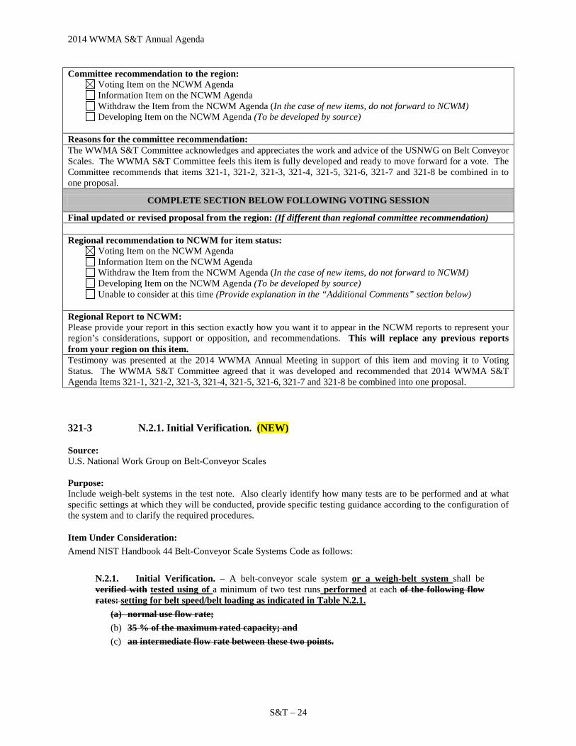
2014 WWMA S&T Annual Agenda
S&T – 24
Committee recommendation to the region: Voting Item on the NCWM Agenda Information Item on the NCWM Agenda Withdraw the Item from the NCWM Agenda (In the case of new items, do not forward to NCWM) Developing Item on the NCWM Agenda (To be developed by source)
Reasons for the committee recommendation: The WWMA S&T Committee acknowledges and appreciates the work and advice of the USNWG on Belt Conveyor Scales. The WWMA S&T Committee feels this item is fully developed and ready to move forward for a vote. The Committee recommends that items 321-1, 321-2, 321-3, 321-4, 321-5, 321-6, 321-7 and 321-8 be combined in to one proposal.
COMPLETE SECTION BELOW FOLLOWING VOTING SESSION
Final updated or revised proposal from the region: (If different than regional committee recommendation) Regional recommendation to NCWM for item status:
Voting Item on the NCWM Agenda Information Item on the NCWM Agenda Withdraw the Item from the NCWM Agenda (In the case of new items, do not forward to NCWM) Developing Item on the NCWM Agenda (To be developed by source) Unable to consider at this time (Provide explanation in the “Additional Comments” section below)
Regional Report to NCWM: Please provide your report in this section exactly how you want it to appear in the NCWM reports to represent your region’s considerations, support or opposition, and recommendations. This will replace any previous reports from your region on this item. Testimony was presented at the 2014 WWMA Annual Meeting in support of this item and moving it to Voting Status. The WWMA S&T Committee agreed that it was developed and recommended that 2014 WWMA S&T Agenda Items 321-1, 321-2, 321-3, 321-4, 321-5, 321-6, 321-7 and 321-8 be combined into one proposal.
321-3 N.2.1. Initial Verification. (NEW)
Source: U.S. National Work Group on Belt-Conveyor Scales Purpose: Include weigh-belt systems in the test note. Also clearly identify how many tests are to be performed and at what specific settings at which they will be conducted, provide specific testing guidance according to the configuration of the system and to clarify the required procedures.
Item Under Consideration: Amend NIST Handbook 44 Belt-Conveyor Scale Systems Code as follows:
N.2.1. Initial Verification. – A belt-conveyor scale system or a weigh-belt system shall be verified with tested using of a minimum of two test runs performed at each of the following flow rates: setting for belt speed/belt loading as indicated in Table N.2.1.
(a) normal use flow rate; (b) 35 % of the maximum rated capacity; and (c) an intermediate flow rate between these two points.

2014 WWMA S&T Annual Agenda
S&T –25
Table N.2.1. Initial Verification
Device Configuration
Minimum of 2 test runs at each of the following settings
Total Tests
(minimum)
Constant belt speed/ Variable
loading
− belt loading: high (normal) − belt loading: medium (intermediate) − belt loading: low (35%)
6
Variable belt speed/ Constant
loading
− belt speed: maximum − belt speed: medium − belt speed: minimum
6
Variable belt speed/ Variable
loading
− speed: maximum / belt loading: high (normal)
− speed: maximum / belt loading: medium (intermediate)
− speed: maximum / belt loading: low (35%) − speed: minimum/ belt loading: high (normal) − speed: minimum/ belt loading: medium
(intermediate) − speed: minimium/ belt loading: low (35%)
12
Use the device configurations in the left-hand column to identify the scale being tested. Perform 2 test runs (minimum) at each of the settings shown in the center column. The following terminology applies: • High: maximum (normal use) operational rate. • Low: 35% of the maximum rated capacity of the system. • Medium: an intermediate rate between the high and low settings.
Results of the individual test runs in each pair of tests shall not differ by more than the absolute value of the tolerance as specified in T.2. Tolerance Values, Repeatability Tests. All tests shall be within the tolerance as specified in T.1. Tolerance Values.
Test runs may also be conducted at any other rate of flow that may be used at the installation. A minimum of four test runs may be conducted at only one flow rate if evidence is provided that the system is used at a single flow rate constant speed/constant loading setting and that rate does not vary in either direction by an amount more than 10 % of the normal flow rate that can be developed at the installation for at least 80 % of the time.
Background / Discussion: The existing N.2.1. mentions specifically “belt-conveyor scale system” in the opening sentence but does not mention weigh-belt systems. The USNWG on Belt-Conveyor Scales agreed that this omission of weigh-belt systems would exclude the HB44 Belt-Conveyor Scale Systems Code from being applied to that type of system. The proposed changes therefore includes the addition of “weigh-belt systems” in this sentence.
In addition, the current language used in N.2.1. does not take into consideration that on some conveyor systems, there can be two separate means to adjust the rate of product flow across the weighing device. The flow of material onto the belt may be increased at the loading point which will result in a higher weight per unit of belt length,
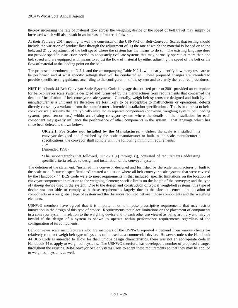
2014 WWMA S&T Annual Agenda
S&T – 26
thereby increasing the rate of material flow across the weighing device or the speed of belt travel may simply be increased which will also result in an increase of material flow rate.
At their February 2014 meeting, it was the consensus of the USNWG on Belt-Conveyor Scales that testing should include the variation of product flow through the adjustment of: 1) the rate at which the material is loaded on to the belt; and 2) by adjustment of the belt speed where the system has the means to do so. The existing language does not provide specific instruction needed to adequately evaluate systems that may normally operate at more than one belt speed and are equipped with means to adjust the flow of material by either adjusting the speed of the belt or the flow of material at the loading point on the belt.
The proposed amendments to N.2.1. and the accompanying Table N.2.1. will clearly identify how many tests are to be performed and at what specific settings they will be conducted at. These proposed changes are intended to provide specific testing guidance according to the configuration of the system and to clarify the required procedures.
NIST Handbook 44 Belt-Conveyor Scale Systems Code language that existed prior to 2001 provided an exemption for belt-conveyor scale systems designed and furnished by the manufacturer from requirements that concerned the details of installation of belt-conveyor scale systems. Generally, weigh-belt systems are designed and built by the manufacturer as a unit and are therefore are less likely to be susceptible to malfunctions or operational defects directly caused by a variance from the manufacturer’s intended installation specifications. This is in contrast to belt-conveyor scale systems that are typically installed as separate components (conveyor, weighing system, belt loading system, speed sensor, etc.) within an existing conveyor system where the details of the installation for each component may greatly influence the performance of other components in the system. That language which has since been deleted is shown below:
UR.2.2.1. For Scales not Installed by the Manufacturer. - Unless the scale is installed in a conveyor designed and furnished by the scale manufacturer or built to the scale manufacturer’s specifications, the conveyor shall comply with the following minimum requirements: …* (Amended 1998)
*The subparagraphs that followed, UR.2.2.1.(a) through (j), consisted of requirements addressing specific criteria related to design and installation of the conveyor system.
The deletion of the statement: “installed in a conveyor designed and furnished by the scale manufacturer or built to the scale manufacturer’s specifications” created a situation where all belt-conveyor scale systems that were covered by the Handbook 44 BCS Code were to meet requirements in that included: specific limitations on the location of conveyor components in relation to the weighing element; specific limits on the length of the conveyor; and the type of take-up device used in the system. Due to the design and construction of typical weigh-belt systems, this type of device was not able to comply with these requirements largely due to the size, placement, and location of components in a weigh-belt type of system and the distances required between those components and the weighing elements.
USNWG members have agreed that it is important not to impose prescriptive requirements that may restrict innovation in the design of this type of device. Requirements that place limitations on the placement of components in a conveyor system in relation to the weighing device and to each other are viewed as being arbitrary and may be invalid if the design of a system is shown to operate within performance requirements regardless of the configuration of its components.
Belt-conveyor scale manufacturers who are members of the USNWG reported a demand from various clients for relatively compact weigh-belt type of systems to be used as a commercial device. However, unless the Handbook 44 BCS Code is amended to allow for their unique design characteristics, there was not an appropriate code in Handbook 44 to apply to weigh-belt systems. The USNWG therefore, has developed a number of proposed changes throughout the existing Belt-Conveyor Scale Systems Code to adapt these requirements so that they may be applied to weigh-belt systems as well.
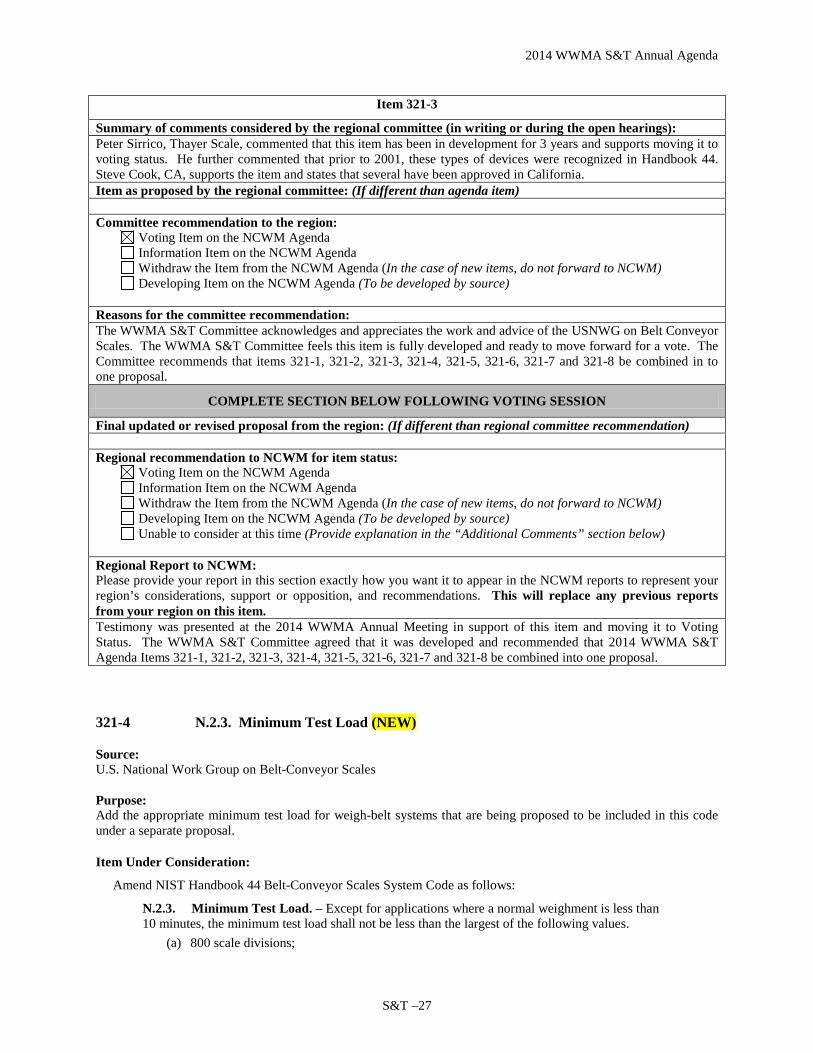
2014 WWMA S&T Annual Agenda
S&T –27
Item 321-3
Summary of comments considered by the regional committee (in writing or during the open hearings): Peter Sirrico, Thayer Scale, commented that this item has been in development for 3 years and supports moving it to voting status. He further commented that prior to 2001, these types of devices were recognized in Handbook 44. Steve Cook, CA, supports the item and states that several have been approved in California. Item as proposed by the regional committee: (If different than agenda item) Committee recommendation to the region:
Voting Item on the NCWM Agenda Information Item on the NCWM Agenda Withdraw the Item from the NCWM Agenda (In the case of new items, do not forward to NCWM) Developing Item on the NCWM Agenda (To be developed by source)
Reasons for the committee recommendation: The WWMA S&T Committee acknowledges and appreciates the work and advice of the USNWG on Belt Conveyor Scales. The WWMA S&T Committee feels this item is fully developed and ready to move forward for a vote. The Committee recommends that items 321-1, 321-2, 321-3, 321-4, 321-5, 321-6, 321-7 and 321-8 be combined in to one proposal.
COMPLETE SECTION BELOW FOLLOWING VOTING SESSION
Final updated or revised proposal from the region: (If different than regional committee recommendation) Regional recommendation to NCWM for item status:
Voting Item on the NCWM Agenda Information Item on the NCWM Agenda Withdraw the Item from the NCWM Agenda (In the case of new items, do not forward to NCWM) Developing Item on the NCWM Agenda (To be developed by source) Unable to consider at this time (Provide explanation in the “Additional Comments” section below)
Regional Report to NCWM: Please provide your report in this section exactly how you want it to appear in the NCWM reports to represent your region’s considerations, support or opposition, and recommendations. This will replace any previous reports from your region on this item. Testimony was presented at the 2014 WWMA Annual Meeting in support of this item and moving it to Voting Status. The WWMA S&T Committee agreed that it was developed and recommended that 2014 WWMA S&T Agenda Items 321-1, 321-2, 321-3, 321-4, 321-5, 321-6, 321-7 and 321-8 be combined into one proposal.
321-4 N.2.3. Minimum Test Load (NEW)
Source: U.S. National Work Group on Belt-Conveyor Scales Purpose: Add the appropriate minimum test load for weigh-belt systems that are being proposed to be included in this code under a separate proposal.
Item Under Consideration:
Amend NIST Handbook 44 Belt-Conveyor Scales System Code as follows:
N.2.3. Minimum Test Load. – Except for applications where a normal weighment is less than 10 minutes, the minimum test load shall not be less than the largest of the following values.
(a) 800 scale divisions;

2014 WWMA S&T Annual Agenda
S&T – 28
(b) the load obtained at maximum flow rate in one revolution of the belt; or at least 10 minutes of operation for belt-conveyor scale systems or, for weigh-belt systems only, at least 1 minute of operation.
Background / Discussion: Since the typical design of weigh-belt systems (see proposal for the addition of a new definition for “weigh-belt systems” in HB44, Appendix D) consists of significantly shorter conveyors compared to those normally found in belt-conveyor scale systems, the time needed for a complete revolution of the belt to occur on a weigh-belt system is much shorter. The USNWG on Belt-Conveyor Scales agreed that due to the generally shorter time needed for a belt revolution on a weigh-belt system, the dynamics of the weigh-belt system could be evaluated without the need of an extended (10 minutes) period of operation as is required for a belt-conveyor scale system. The USNWG concluded that the weigh-belt systems could be sufficiently evaluated over a shorter time span and recommended that, as a minimum, 1 minute of operation would suffice.
Longer periods of operation of a belt-conveyor or weigh-belt system during a test will provide more time in which the effects of extreme low and high points of belt loading would be mitigated since these highs and lows are averaged into the total load. The high and low points of the belt loading would be seen during the start-up of the conveyor when material is just beginning to be loaded on the belt and then when the flow of material is cut off at the end of a “run” where a gradual decrease of material on the belt occurs. These extremes of belt loading would comprise a larger proportion of the total load during shorter periods of operation and could expose errors caused by inconsistent belt loading or other problems within the system. This could be interpreted that a test comprised of a shorter duration would be more stringent than one of a longer duration.
NIST Handbook 44 Belt-Conveyor Scale Systems Code language that existed prior to 2001 provided an exemption for belt-conveyor scale systems designed and furnished by the manufacturer from requirements that concerned the details of installation of belt-conveyor scale systems. Generally, weigh-belt systems are designed and built by the manufacturer as a unit and are therefore are less likely to be susceptible to malfunctions or operational defects directly caused by a variance from the manufacturer’s intended installation specifications. This is in contrast to belt-conveyor scale systems that are typically installed as separate components (conveyor, weighing system, belt loading system, speed sensor, etc.) within an existing conveyor system where the details of the installation for each component may greatly influence the performance of other components in the system. That language which has since been deleted is shown below:
UR.2.2.1. For Scales not Installed by the Manufacturer. - Unless the scale is installed in a conveyor designed and furnished by the scale manufacturer or built to the scale manufacturer’s specifications, the conveyor shall comply with the following minimum requirements: …* (Amended 1998)
*The subparagraphs that followed, UR.2.2.1.(a) through (j), consisted of requirements addressing specific criteria related to design and installation of the conveyor system.
The deletion of the statement: “installed in a conveyor designed and furnished by the scale manufacturer or built to the scale manufacturer’s specifications” created a situation where all belt-conveyor scale systems that were covered by the Handbook 44 BCS Code were to meet requirements in that included: specific limitations on the location of conveyor components in relation to the weighing element; specific limits on the length of the conveyor; and the type of take-up device used in the system. Due to the design and construction of typical weigh-belt systems, this type of device was not able to comply with these requirements largely due to the size, placement, and location of components in a weigh-belt type of system and the distances required between those components and the weighing elements.
USNWG members have agreed that it is important not to impose prescriptive requirements that may restrict innovation in the design of this type of device. Requirements that place limitations on the placement of components in a conveyor system in relation to the weighing device and to each other are viewed as being arbitrary and may be invalid if the design of a system is shown to operate within performance requirements regardless of the configuration of its components.

2014 WWMA S&T Annual Agenda
S&T –29
Belt-conveyor scale manufacturers who are members of the USNWG reported a demand from various clients for relatively compact weigh-belt type of systems to be used as a commercial device. However, unless the Handbook 44 BCS Code is amended to allow for their unique design characteristics, there was not an appropriate code in Handbook 44 to apply to weigh-belt systems. The USNWG therefore, has developed a number of proposed changes throughout the existing Belt-Conveyor Scale Systems Code to adapt these requirements so that they may be applied to weigh-belt systems as well.
Item 321-4
Summary of comments considered by the regional committee (in writing or during the open hearings): Peter Sirrico, Thayer Scale, commented that this item has been in development for 3 years and supports moving it to voting status. He further commented that prior to 2001, these types of devices were recognized in Handbook 44. Steve Cook, CA, supports the item and states that several have been approved in California. Item as proposed by the regional committee: (If different than agenda item) Committee recommendation to the region:
Voting Item on the NCWM Agenda Information Item on the NCWM Agenda Withdraw the Item from the NCWM Agenda (In the case of new items, do not forward to NCWM) Developing Item on the NCWM Agenda (To be developed by source)
Reasons for the committee recommendation: The WWMA S&T Committee acknowledges and appreciates the work and advice of the USNWG on Belt Conveyor Scales. The WWMA S&T Committee feels this item is fully developed and ready to move forward for a vote. The Committee recommends that items 321-1, 321-2, 321-3, 321-4, 321-5, 321-6, 321-7 and 321-8 be combined in to one proposal.
COMPLETE SECTION BELOW FOLLOWING VOTING SESSION
Final updated or revised proposal from the region: (If different than regional committee recommendation) Regional recommendation to NCWM for item status:
Voting Item on the NCWM Agenda Information Item on the NCWM Agenda Withdraw the Item from the NCWM Agenda (In the case of new items, do not forward to NCWM) Developing Item on the NCWM Agenda (To be developed by source) Unable to consider at this time (Provide explanation in the “Additional Comments” section below)
Regional Report to NCWM: Please provide your report in this section exactly how you want it to appear in the NCWM reports to represent your region’s considerations, support or opposition, and recommendations. This will replace any previous reports from your region on this item. Testimony was presented at the 2014 WWMA Annual Meeting in support of this item and moving it to Voting Status. The WWMA S&T Committee agreed that it was developed and recommended that 2014 WWMA S&T Agenda Items 321-1, 321-2, 321-3, 321-4, 321-5, 321-6, 321-7 and 321-8 be combined into one proposal.
321-5 N.2.1.1. Determination of Zero. (NEW)
Source: U.S. National Work Group on Belt-Conveyor Scales Purpose: Segregating the requirements for belt-conveyor scales that use electronic integrators from those that use mechanical integrators and add weigh-belt systems to the Code.

2014 WWMA S&T Annual Agenda
S&T – 30
Item Under Consideration: Amend NIST Handbook 44 Belt-Conveyor Scale Systems Code as follows:
N.3.1.1. Determination of Zero. – A zero-load test is a determination of the error in zero, expressed as an internal reference, a percentage of the full-scale capacity, or a change in a totalized load over a whole number of complete belt revolutions. For belt-conveyor scales with electronic integrators, the test must be performed over a period of at least three minutes and with a whole number of complete belt revolutions. For belt-conveyor scales with mechanical integrators, the test shall be performed with no less than three complete revolutions or 10 minutes of operation, whichever is greater. A zero-load test shall be performed as follows:
(a) For belt-conveyor scales with electronic integrators, the test must be performed over a period of at least 3 minutes and with a whole number of complete belt revolutions;
(b) For belt-conveyor scales with mechanical integrators, the test shall be performed with no less than three complete revolutions or 10 minutes of operation, whichever is greater;
(c) For weigh belt systems the test must be performed over a period of at least one minute and at least one complete revolution of the belt.
(Added 2002) (Amended 20XX)
Background / Discussion: Since the typical design of weigh-belt systems (see proposal to add definition in Appendix D for “weigh-belt systems) consists of significantly shorter conveyors compared to those normally found in belt-conveyor scale systems, the time needed for a complete revolution of the belt to occur on a weigh-belt system is much shorter. The USNWG on Belt-Conveyor Scales agreed that due to the generally shorter time needed for a belt revolution on a weigh-belt system, the dynamics of the weigh-belt system (including the ability to maintain a zero load reference) could be evaluated without the need of an extended (10 minutes) period of operation as is required for a belt-conveyor scale system. The USNWG concluded that the weigh-belt system’s ability to maintain a stable zero condition could be sufficiently evaluated over a shorter time span and recommended that, as a minimum, 1 minute of operation would suffice. This provision has been added in bullet point (c).
This proposed amendment is also considered to improve the structure of the existing language of the requirement by segregating the requirements for belt-conveyor scales that use electronic integrators from those that use mechanical integrators into bullet points (a) and (b).
NIST Handbook 44 Belt-Conveyor Scale Systems Code language that existed prior to 2001 provided an exemption for belt-conveyor scale systems designed and furnished by the manufacturer from requirements that concerned the details of installation of belt-conveyor scale systems. Generally, weigh-belt systems are designed and built by the manufacturer as a unit and are therefore are less likely to be susceptible to malfunctions or operational defects directly caused by a variance from the manufacturer’s intended installation specifications. This is in contrast to belt-conveyor scale systems that are typically installed as separate components (conveyor, weighing system, belt loading system, speed sensor, etc.) within an existing conveyor system where the details of the installation for each component may greatly influence the performance of other components in the system. That language which has since been deleted is shown below:
UR.2.2.1. For Scales not Installed by the Manufacturer. - Unless the scale is installed in a conveyor designed and furnished by the scale manufacturer or built to the scale manufacturer’s specifications, the conveyor shall comply with the following minimum requirements: …* (Amended 1998)
*The subparagraphs that followed, UR.2.2.1.(a) through (j), consisted of requirements addressing specific criteria related to design and installation of the conveyor system.
The deletion of the statement: “installed in a conveyor designed and furnished by the scale manufacturer or built to the scale manufacturer’s specifications” created a situation where all belt-conveyor scale systems that were covered by the Handbook 44 BCS Code were to meet requirements in that included: specific limitations on the location of conveyor components in relation to the weighing element; specific limits on the length of the conveyor; and the type

2014 WWMA S&T Annual Agenda
S&T –31
of take-up device used in the system. Due to the design and construction of typical weigh-belt systems, this type of device was not able to comply with these requirements largely due to the size, placement, and location of components in a weigh-belt type of system and the distances required between those components and the weighing elements.
USNWG members have agreed that it is important not to impose prescriptive requirements that may restrict innovation in the design of this type of device. Requirements that place limitations on the placement of components in a conveyor system in relation to the weighing device and to each other are viewed as being arbitrary and may be invalid if the design of a system is shown to operate within performance requirements regardless of the configuration of its components.
Belt-conveyor scale manufacturers who are members of the USNWG reported a demand from various clients for relatively compact weigh-belt type of systems to be used as a commercial device. However, unless the Handbook 44 BCS Code is amended to allow for their unique design characteristics, there was not an appropriate code in Handbook 44 to apply to weigh-belt systems. The USNWG therefore, has developed a number of proposed changes throughout the existing Belt-Conveyor Scale Systems Code to adapt these requirements so that they may be applied to weigh-belt systems as well.
Item 321-5
Summary of comments considered by the regional committee (in writing or during the open hearings): Peter Sirrico, Thayer Scale, commented that this item has been in development for 3 years and supports moving it to voting status. He further commented that prior to 2001, these types of devices were recognized in Handbook 44. Steve Cook, CA, supports the item and states that several have been approved in California. Item as proposed by the regional committee: (If different than agenda item) Committee recommendation to the region:
Voting Item on the NCWM Agenda Information Item on the NCWM Agenda Withdraw the Item from the NCWM Agenda (In the case of new items, do not forward to NCWM) Developing Item on the NCWM Agenda (To be developed by source)
Reasons for the committee recommendation: The WWMA S&T Committee acknowledges and appreciates the work and advice of the USNWG on Belt Conveyor Scales. The WWMA S&T Committee feels this item is fully developed and ready to move forward for a vote. The Committee recommends that items 321-1, 321-2, 321-3, 321-4, 321-5, 321-6, 321-7 and 321-8 be combined in to one proposal.
COMPLETE SECTION BELOW FOLLOWING VOTING SESSION
Final updated or revised proposal from the region: (If different than regional committee recommendation) Regional recommendation to NCWM for item status:
Voting Item on the NCWM Agenda Information Item on the NCWM Agenda Withdraw the Item from the NCWM Agenda (In the case of new items, do not forward to NCWM) Developing Item on the NCWM Agenda (To be developed by source) Unable to consider at this time (Provide explanation in the “Additional Comments” section below)
Regional Report to NCWM: Please provide your report in this section exactly how you want it to appear in the NCWM reports to represent your region’s considerations, support or opposition, and recommendations. This will replace any previous reports from your region on this item. Testimony was presented at the 2014 WWMA Annual Meeting in support of this item and moving it to Voting Status. The WWMA S&T Committee agreed that it was developed and recommended that 2014 WWMA S&T Agenda Items 321-1, 321-2, 321-3, 321-4, 321-5, 321-6, 321-7 and 321-8 be combined into one proposal.
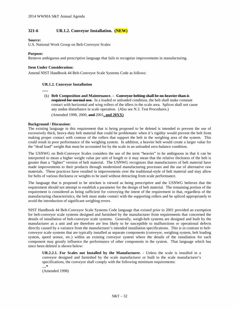
2014 WWMA S&T Annual Agenda
S&T – 32
321-6 UR.1.2. Conveyor Installation. (NEW)
Source: U.S. National Work Group on Belt-Conveyor Scales Purpose: Remove ambiguous and prescriptive language that fails to recognize improvements in manufacturing.
Item Under Consideration: Amend NIST Handbook 44 Belt-Conveyor Scale Systems Code as follows:
UR.1.2. Conveyor Installation ......
(k) Belt Composition and Maintenance. – Conveyor belting shall be no heavier than is required for normal use. In a loaded or unloaded condition, the belt shall make constant contact with horizontal and wing rollers of the idlers in the scale area. Splices shall not cause any undue disturbance in scale operation. (Also see N.3. Test Procedures.) (Amended 1998, 2000, and 2001, and 20XX)
Background / Discussion: The existing language in this requirement that is being proposed to be deleted is intended to prevent the use of excessively thick, heavy-duty belt material that could be problematic when it’s rigidity would prevent the belt from making proper contact with contour of the rollers that support the belt in the weighing area of the system. This could result in poor performance of the weighing system. In addition, a heavier belt would create a larger value for the “dead load” weight that must be accounted for by the scale in an unloaded zero-balance condition.
The USNWG on Belt-Conveyor Scales considers the use of the term “heavier” to be ambiguous in that it can be interpreted to mean a higher weight value per unit of length or it may mean that the relative thickness of the belt is greater than a “lighter” version of belt material. The USNWG recognizes that manufacturers of belt material have made improvements to their products through modernized manufacturing processes and the use of alternative raw materials. These practices have resulted in improvements over the traditional-style of belt material and may allow for belts of various thickness or weights to be used without detracting from scale performance.
The language that is proposed to be stricken is viewed as being prescriptive and the USNWG believes that the requirement should not attempt to establish a parameter for the design of belt material. The remaining portion of the requirement is considered as being sufficient for conveying the intent of the requirement in that, regardless of the manufacturing characteristics, the belt must make contact with the supporting rollers and be spliced appropriately to avoid the introduction of significant weighing errors.
NIST Handbook 44 Belt-Conveyor Scale Systems Code language that existed prior to 2001 provided an exemption for belt-conveyor scale systems designed and furnished by the manufacturer from requirements that concerned the details of installation of belt-conveyor scale systems. Generally, weigh-belt systems are designed and built by the manufacturer as a unit and are therefore are less likely to be susceptible to malfunctions or operational defects directly caused by a variance from the manufacturer’s intended installation specifications. This is in contrast to belt-conveyor scale systems that are typically installed as separate components (conveyor, weighing system, belt loading system, speed sensor, etc.) within an existing conveyor system where the details of the installation for each component may greatly influence the performance of other components in the system. That language which has since been deleted is shown below:
UR.2.2.1. For Scales not Installed by the Manufacturer. - Unless the scale is installed in a conveyor designed and furnished by the scale manufacturer or built to the scale manufacturer’s specifications, the conveyor shall comply with the following minimum requirements: …* (Amended 1998)
2014 WWMA S&T Annual Agenda
S&T –33
*The subparagraphs that followed, UR.2.2.1.(a) through (j), consisted of requirements addressing specific criteria related to design and installation of the conveyor system.
The deletion of the statement: “installed in a conveyor designed and furnished by the scale manufacturer or built to the scale manufacturer’s specifications” created a situation where all belt-conveyor scale systems that were covered by the Handbook 44 BCS Code were to meet requirements in that included: specific limitations on the location of conveyor components in relation to the weighing element; specific limits on the length of the conveyor; and the type of take-up device used in the system. Due to the design and construction of typical weigh-belt systems, this type of device was not able to comply with these requirements largely due to the size, placement, and location of components in a weigh-belt type of system and the distances required between those components and the weighing elements.
USNWG members have agreed that it is important not to impose prescriptive requirements that may restrict innovation in the design of this type of device. Requirements that place limitations on the placement of components in a conveyor system in relation to the weighing device and to each other are viewed as being arbitrary and may be invalid if the design of a system is shown to operate within performance requirements regardless of the configuration of its components.
Belt-conveyor scale manufacturers who are members of the USNWG reported a demand from various clients for relatively compact weigh-belt type of systems to be used as a commercial device. However, unless the Handbook 44 BCS Code is amended to allow for their unique design characteristics, there was not an appropriate code in Handbook 44 to apply to weigh-belt systems. The USNWG therefore, has developed a number of proposed changes throughout the existing Belt-Conveyor Scale Systems Code to adapt these requirements so that they may be applied to weigh-belt systems as well.
Item 321-6
Summary of comments considered by the regional committee (in writing or during the open hearings): Peter Sirrico, Thayer Scale, commented that this item has been in development for 3 years and supports moving it to voting status. He further commented that prior to 2001, these types of devices were recognized in Handbook 44. Steve Cook, CA, supports the item and states that several have been approved in California. Item as proposed by the regional committee: (If different than agenda item) Committee recommendation to the region:
Voting Item on the NCWM Agenda Information Item on the NCWM Agenda Withdraw the Item from the NCWM Agenda (In the case of new items, do not forward to NCWM) Developing Item on the NCWM Agenda (To be developed by source)
Reasons for the committee recommendation: The WWMA S&T Committee acknowledges and appreciates the work and advice of the USNWG on Belt Conveyor Scales. The WWMA S&T Committee feels this item is fully developed and ready to move forward for a vote. The Committee recommends that items 321-1, 321-2, 321-3, 321-4, 321-5, 321-6, 321-7 and 321-8 be combined in to one proposal.
COMPLETE SECTION BELOW FOLLOWING VOTING SESSION
Final updated or revised proposal from the region: (If different than regional committee recommendation) Regional recommendation to NCWM for item status:
Voting Item on the NCWM Agenda Information Item on the NCWM Agenda Withdraw the Item from the NCWM Agenda (In the case of new items, do not forward to NCWM) Developing Item on the NCWM Agenda (To be developed by source) Unable to consider at this time (Provide explanation in the “Additional Comments” section below)
Regional Report to NCWM: Please provide your report in this section exactly how you want it to appear in the NCWM reports to represent your
2014 WWMA S&T Annual Agenda
S&T – 34
region’s considerations, support or opposition, and recommendations. This will replace any previous reports from your region on this item. Testimony was presented at the 2014 WWMA Annual Meeting in support of this item and moving it to Voting Status. The WWMA S&T Committee agreed that it was developed and recommended that 2014 WWMA S&T Agenda Items 321-1, 321-2, 321-3, 321-4, 321-5, 321-6, 321-7 and 321-8 be combined into one proposal.
321-7 UR.3.1. Scale and Conveyor Maintenance. – Belt-conveyor scalesWeighing systems. (NEW)
Source: U.S. National Work Group on Belt-Conveyor Scales Purpose: Allow the requirement to apply to weigh-belt systems and require alignment checks whenever work is performed on weigh-belt systems as well as belt-conveyor scale systems that may alter the alignment.
Item Under Consideration: Amend NIST Handbook 44 Belt-Conveyor Scale Systems Code as follows:
UR.3.1. Scale and Conveyor Maintenance. – Belt-conveyor scalesWeighing systems and idlers shall be maintained and serviced in accordance with manufacturer’s instructions and the following:
… . . (e) Scale Alignment. – Alignment checks shall be conducted in accordance with the
manufacturer’s recommendation when conveyor work is performed in the scale area. A material test is required after any realignment.
(Amended 1986, and 2000, and 20XX)
Background / Discussion: The USNWG on Belt-Conveyor Scales have proposed a number of changes to the HB44 BCS Code intended to allow the Code to be applied to “weigh-belt systems” as well as belt-conveyor scale systems. To facilitate this effort references to “belt-conveyor scales” are being proposed to be changed to a more inclusive terminology such as is recommended in the first sentence in UR.3.1. (See also remarks in “Additional Considerations” below). This proposed change is intended to eliminate the exclusion of weigh-belt systems from this requirement.
Since the typical design of weigh-belt systems (see proposal for the addition of a new definition for “weigh-belt systems” in HB44, Appendix D) consists of an all-inclusive unit and significantly shorter conveyors as compared to those normally found in belt-conveyor scale system, any work performed on weigh-belt systems could possibly be considered to take place “in the scale area.” Any misalignment of the conveyor belt during its operation can have a detrimental effect on the performance of the system.
The USNWG on BCS agreed that it is appropriate to require alignment checks whenever work is performed on weigh-belt systems (as well as belt-conveyor scale systems) that may alter this alignment. The USNWG members who are employees of device manufacturers have stated that the manufacturers of weigh-belt systems will emphasize the critical nature of belt alignment and will specify that owners/operators check the belt alignment if work is performed on the conveyor system that could have any effect on this. Therefore, the USNWG agreed that the proposed change to require an alignment check to be done according to manufacturer’s instructions is a sound basis for this user requirement.
NIST Handbook 44 Belt-Conveyor Scale Systems Code language that existed prior to 2001 provided an exemption for belt-conveyor scale systems designed and furnished by the manufacturer from requirements that concerned the details of installation of belt-conveyor scale systems. Generally, weigh-belt systems are designed and built by the

2014 WWMA S&T Annual Agenda
S&T –35
manufacturer as a unit and are therefore are less likely to be susceptible to malfunctions or operational defects directly caused by a variance from the manufacturer’s intended installation specifications. This is in contrast to belt-conveyor scale systems that are typically installed as separate components (conveyor, weighing system, belt loading system, speed sensor, etc.) within an existing conveyor system where the details of the installation for each component may greatly influence the performance of other components in the system. That language which has since been deleted is shown below:
UR.2.2.1. For Scales not Installed by the Manufacturer. - Unless the scale is installed in a conveyor designed and furnished by the scale manufacturer or built to the scale manufacturer’s specifications, the conveyor shall comply with the following minimum requirements: …* (Amended 1998)
*The subparagraphs that followed, UR.2.2.1.(a) through (j), consisted of requirements addressing specific criteria related to design and installation of the conveyor system.
The deletion of the statement: “installed in a conveyor designed and furnished by the scale manufacturer or built to the scale manufacturer’s specifications” created a situation where all belt-conveyor scale systems that were covered by the Handbook 44 BCS Code were to meet requirements in that included: specific limitations on the location of conveyor components in relation to the weighing element; specific limits on the length of the conveyor; and the type of take-up device used in the system. Due to the design and construction of typical weigh-belt systems, this type of device was not able to comply with these requirements largely due to the size, placement, and location of components in a weigh-belt type of system and the distances required between those components and the weighing elements.
USNWG members have agreed that it is important not to impose prescriptive requirements that may restrict innovation in the design of this type of device. Requirements that place limitations on the placement of components in a conveyor system in relation to the weighing device and to each other are viewed as being arbitrary and may be invalid if the design of a system is shown to operate within performance requirements regardless of the configuration of its components.
Belt-conveyor scale manufacturers who are members of the USNWG reported a demand from various clients for relatively compact weigh-belt type of systems to be used as a commercial device. However, unless the Handbook 44 BCS Code is amended to allow for their unique design characteristics, there was not an appropriate code in Handbook 44 to apply to weigh-belt systems. The USNWG therefore, has developed a number of proposed changes throughout the existing Belt-Conveyor Scale Systems Code to adapt these requirements so that they may be applied to weigh-belt systems as well.
Item 321-7
Summary of comments considered by the regional committee (in writing or during the open hearings): Peter Sirrico, Thayer Scale, commented that this item has been in development for 3 years and supports moving it to voting status. He further commented that prior to 2001, these types of devices were recognized in Handbook 44. Steve Cook, CA, supports the item and states that several have been approved in California. Item as proposed by the regional committee: (If different than agenda item) Committee recommendation to the region:
Voting Item on the NCWM Agenda Information Item on the NCWM Agenda Withdraw the Item from the NCWM Agenda (In the case of new items, do not forward to NCWM) Developing Item on the NCWM Agenda (To be developed by source)
Reasons for the committee recommendation: The WWMA S&T Committee acknowledges and appreciates the work and advice of the USNWG on Belt Conveyor Scales. The WWMA S&T Committee feels this item is fully developed and ready to move forward for a vote. The Committee recommends that items 321-1, 321-2, 321-3, 321-4, 321-5, 321-6, 321-7 and 321-8 be combined in to one proposal.
2014 WWMA S&T Annual Agenda
S&T – 36
COMPLETE SECTION BELOW FOLLOWING VOTING SESSION
Final updated or revised proposal from the region: (If different than regional committee recommendation) Regional recommendation to NCWM for item status:
Voting Item on the NCWM Agenda Information Item on the NCWM Agenda Withdraw the Item from the NCWM Agenda (In the case of new items, do not forward to NCWM) Developing Item on the NCWM Agenda (To be developed by source) Unable to consider at this time (Provide explanation in the “Additional Comments” section below)
Regional Report to NCWM: Please provide your report in this section exactly how you want it to appear in the NCWM reports to represent your region’s considerations, support or opposition, and recommendations. This will replace any previous reports from your region on this item. Testimony was presented at the 2014 WWMA Annual Meeting in support of this item and moving it to Voting Status. The WWMA S&T Committee agreed that it was developed and recommended that 2014 WWMA S&T Agenda Items 321-1, 321-2, 321-3, 321-4, 321-5, 321-6, 321-7 and 321-8 be combined into one proposal.
321-8 Appendix D – Definitions. weigh-belt systems. (NEW)
Source: U.S. National Work Group on Belt-Conveyor Scales Purpose: Provide a definition for this device type if other proposals are adopted that would reference it in the Belt-Conveyor Scales Code.
Item Under Consideration: Amend NIST Handbook 44 Appendix D – Definitions as follows:
weigh-belt systems. – A type of belt-conveyor scale system designed by the manufacturer as a self-contained conveyor system and which is installed as a unit. The units are comprised of integral components including as a minimum: conveyor belt; belt drive; conveyor frame; and weighing system. They may operate at single or multiple flow rates and may use variable-speed belt drives
Background / Discussion: Based on the submission of proposed changes to the HB44 Belt-Conveyor Scale Systems Code that are intended to facilitate the application of that code to a specific, self-contained type of design devices commonly referred to as “weigh-belt systems,” the USNWG on Belt-Conveyor Scales (BCS) agreed that it is necessary to establish a definition for this type of device. This definition would help to distinguish the weigh-belt type of systems from the more familiar belt-conveyor scale systems. Several terms have been used to describe relatively shorter conveyor systems including “weigh-belts” and “weigh-feeders.” The USNWG agreed that the term “weigh-belt system” is best suited for describing this type of device. The work group also agreed that if this term is to be understood and routinely used to describe a specific type of weighing device/system, then a definition should be developed to be included in HB44 Appendix D (Definitions).
NIST Handbook 44 Belt-Conveyor Scale Systems Code language that existed prior to 2001 provided an exemption for belt-conveyor scale systems designed and furnished by the manufacturer from requirements that concerned the details of installation of belt-conveyor scale systems. Generally, weigh-belt systems are designed and built by the manufacturer as a unit and are therefore are less likely to be susceptible to malfunctions or operational defects directly caused by a variance from the manufacturer’s intended installation specifications. This is in contrast to belt-

2014 WWMA S&T Annual Agenda
S&T –37
conveyor scale systems that are typically installed as separate components (conveyor, weighing system, belt loading system, speed sensor, etc.) within an existing conveyor system where the details of the installation for each component may greatly influence the performance of other components in the system. That language which has since been deleted is shown below:
UR.2.2.1. For Scales not Installed by the Manufacturer. - Unless the scale is installed in a conveyor designed and furnished by the scale manufacturer or built to the scale manufacturer’s specifications, the conveyor shall comply with the following minimum requirements: …* (Amended 1998)
*The subparagraphs that followed, UR.2.2.1.(a) through (j), consisted of requirements addressing specific criteria related to design and installation of the conveyor system.
The deletion of the statement: “installed in a conveyor designed and furnished by the scale manufacturer or built to the scale manufacturer’s specifications” created a situation where all belt-conveyor scale systems that were covered by the Handbook 44 BCS Code were to meet requirements in that included: specific limitations on the location of conveyor components in relation to the weighing element; specific limits on the length of the conveyor; and the type of take-up device used in the system. Due to the design and construction of typical weigh-belt systems, this type of device was not able to comply with these requirements largely due to the size, placement, and location of components in a weigh-belt type of system and the distances required between those components and the weighing elements.
USNWG members have agreed that it is important not to impose prescriptive requirements that may restrict innovation in the design of this type of device. Requirements that place limitations on the placement of components in a conveyor system in relation to the weighing device and to each other are viewed as being arbitrary and may be invalid if the design of a system is shown to operate within performance requirements regardless of the configuration of its components.
Belt-conveyor scale manufacturers who are members of the USNWG reported a demand from various clients for relatively compact weigh-belt type of systems to be used as a commercial device. However, unless the Handbook 44 BCS Code is amended to allow for their unique design characteristics, there was not an appropriate code in Handbook 44 to apply to weigh-belt systems. The USNWG therefore, has developed a number of proposed changes throughout the existing Belt-Conveyor Scale Systems Code to adapt these requirements so that they may be applied to weigh-belt systems as well.
Item 321-8
Summary of comments considered by the regional committee (in writing or during the open hearings): Peter Sirrico, Thayer Scale, commented that this item has been in development for 3 years and supports moving it to voting status. He further commented that prior to 2001, these types of devices were recognized in Handbook 44. Steve Cook, CA, supports the item and states that several have been approved in California. Item as proposed by the regional committee: (If different than agenda item) Committee recommendation to the region:
Voting Item on the NCWM Agenda Information Item on the NCWM Agenda Withdraw the Item from the NCWM Agenda (In the case of new items, do not forward to NCWM) Developing Item on the NCWM Agenda (To be developed by source)
Reasons for the committee recommendation: The WWMA S&T Committee acknowledges and appreciates the work and advice of the USNWG on Belt Conveyor Scales. The WWMA S&T Committee feels this item is fully developed and ready to move forward for a vote. The Committee recommends that items 321-1, 321-2, 321-3, 321-4, 321-5, 321-6, 321-7 and 321-8 be combined in to one proposal.
COMPLETE SECTION BELOW FOLLOWING VOTING SESSION
Final updated or revised proposal from the region: (If different than regional committee recommendation)

2014 WWMA S&T Annual Agenda
S&T – 38
Regional recommendation to NCWM for item status:
Voting Item on the NCWM Agenda Information Item on the NCWM Agenda Withdraw the Item from the NCWM Agenda (In the case of new items, do not forward to NCWM) Developing Item on the NCWM Agenda (To be developed by source) Unable to consider at this time (Provide explanation in the “Additional Comments” section below)
Regional Report to NCWM: Please provide your report in this section exactly how you want it to appear in the NCWM reports to represent your region’s considerations, support or opposition, and recommendations. This will replace any previous reports from your region on this item. Testimony was presented at the 2014 WWMA Annual Meeting in support of this item and moving it to Voting Status. The WWMA S&T Committee agreed that it was developed and recommended that 2014 WWMA S&T Agenda Items 321-1, 321-2, 321-3, 321-4, 321-5, 321-6, 321-7 and 321-8 be combined into one proposal.
322 AUTOMATIC BULK WEIGHING SYSTEMS
322-1 N.1. Testing Procedures (NEW)
Source: Oregon
Purpose: Modify the test method to reflect as-used dynamic conditions.
Item Under Consideration: Amend NIST Handbook 44 Automatic Bulk Weighing Systems Code as follows:
N.1. Testing Procedures. N.1.1. Test Weights. – The increasing load test shall be conducted using test weights equal to at least 10 % of the capacity of the system:
(a) on automatic grain bulk-weighing systems installed after January 1, 1984; and (b) on other automatic bulk-weighing systems installed after January 1, 1986.
(Amended 1987)
N.1.2. Increasing-Load Test. – An increasing-load test consisting of substitution and strain-load tests shall be conducted up to the used capacity of the weighing system. (Amended 1987)
N.1.3. Decreasing-Load Test. – A decreasing-load test shall be conducted on devices used to weigh out. (Added 1986)
N.1.1. Material Tests. – Material used for test must be the actual material weighed by system or similar in nature. Material tests should be conducted using actual scale loading conditions. These loading conditions shall include, three accumulation tests consisting of three loadings at maximum capacity for the material and a partial loading of between 30% and 50% (three and a partial loadings).

2014 WWMA S&T Annual Agenda
S&T –39
On subsequent verifications, at least two individual accumulation tests shall be conducted. The results of all tests shall be within tolerance limits.
Either pass a quantity of pre-weighed material through the Automatic Bulk Weighing system in a manner as similar as feasible to actual loading conditions, or weigh all material that has passed through the Automatic Bulk Weighing System. Means for weighing the material test load will depend on the capacity of the system and availability of a suitable scale for the test. To assure that the test load is accurately weighed and determined, the following precautions shall be observed:
(a) The containers, whether railroad cars, trucks, or boxes, must not leak, and shall not be overloaded to the point that material will be lost.
(b) The actual empty or tare weight of the containers shall be determined at the time of the test. Stenciled tare weight of railway cars, trucks or boxes shall not be used. Gross and tare weights shall be determined on the same scale.
(c) When a pre-weighed test load is passed through the scale, the loading system shall be examined before and after the test to assure that the system is empty and that only the material of the test load has passed through the scale.
(d) Where practicable, a reference scale should be tested within 24 hours preceding the determination of the weight of the test load used for a Automatic Bulk Weighing System material test.
A reference scale which is not “as found” within maintenance tolerance should have its accuracy re-verified after the Automatic Bulk Weighing System test with a suitable known weight load if the “as found” error of the Automatic Bulk Weighing System material test exceeds maintenance tolerance values.*
(e) If any suitable known weight load other than a certified test weight load is used for re-verification of the reference scale accuracy, its weight shall be determined on the reference scale after the reference scale certification and before commencing the Automatic Bulk Weighing System material test.*
(f) The test shall not be conducted if the weight of the test load has been affected by environmental conditions.
*Note: Even if the reference scale is within maintenance tolerance it may require
adjusting to be able to meet paragraph N.1.1.1. Accuracy of Material.

2014 WWMA S&T Annual Agenda
S&T – 40
N.1.1.1. Accuracy of Material. – The quantity of material used to conduct a material test shall be weighed on a reference scale to an accuracy within 0.1 %. Scales typically used for this purpose include Class III and III L scales or a scale without a class designation as described in Handbook 44, Section 2.20., Table T.1.1. Tolerances for Unmarked Scales.
N.1.1.2. Associated Equipment. – All associated equipment in local vicinity shall be in operation at time of test. This would include items such as conveyors; tote dumps, cleaning drums, rock separators, ect.
N.1.4. N.1.2. Zero-Balance or No-Load Reference Value Change Test. – A test for change of zero-balance or no-load reference value shall be conducted on all scales after the removal of any test load. The change shall not be more than the minimum tolerance applicable.
N.1.5. N.1.3 Discrimination Test. – A discrimination test shall be conducted on all automatic indicating scales with the weighing device in equilibrium at zero-load and at maximum test load, and under controlled conditions in which environmental factors are reduced to the extent that they will not affect the results obtained. [Nonretroactive as of January 1, 1986]
N.1.5.1. N.1.3.1. Digital Device. – On a digital device, this test is conducted from just below the lower edge of the zone of uncertainty for increasing-load tests, or from just above the upper edge of the zone of uncertainty for decreasing-load tests. (Added 1987)
T.1.2. To Increasing-Load Tests. – Basic tolerances shall be applied.
T.1.3. To Decreasing-Load Tests. – Basic tolerances shall be applied to systems used to weigh out. (Added 1986)
T.1.4. T.1.2. To Tests Involving Digital Indications or Representations. – To the tolerances that would otherwise be applied, there shall be added an amount equal to one-half the value of the scale division. This does not apply to digital indications or recorded representations that have been corrected for rounding using error weights. (Added 1986)
T.3. Basic Tolerance Values. T.3.1. Acceptance Tolerance. – The basic acceptance tolerance shall be one-half the basic maintenance tolerance.
T.3.2. For Systems Used to Weigh Grain. – The basic maintenance tolerance shall be 0.1 % of test load accumulation material test.
T.3.3. For All Other Systems. – The basic maintenance tolerance shall be 0.2 % of test load accumulation material test. (Amended 1986)
T.5. Repeatability. – The results obtained by several weighings of the same load under reasonably static test conditions variation in the values obtained during the conduct of accumulation material tests shall agree within the absolute value of the maintenance tolerance for that load, and shall be within applicable tolerances.
(Added 1986)

2014 WWMA S&T Annual Agenda
S&T –41
Background / Discussion: The purpose of this proposal to change the test and tolerances to reflect the way these devices are actually used. These are not “static” devices they are “dynamic”. Being dynamic they have many additional factors affecting their accuracy compared to static devices. Some of these additional factors are: timing of gates and conveyors, additional vibration from system while trying to capture weight, operation of software, characteristics of materials being weighed, environmental situations. While evaluating Automatic Bulk Weighing Systems in the State of Oregon it was found that devices meeting static testing tolerances were in fact weighing with errors as high as 6%. Through investigation it was found that a high percentage of the Automatic Bulk Weighing Systems in the state were in fact weighing in error when operating in their normal dynamic mode. These same devices would of received approval using only static methods. The fundamentals of testing call for “testing as used” this proposal lays out a method to do exactly that “test as used”. Some facilities may find it difficult to accommodate the material test method. There may be substantial cost in restructuring facilities to allow for either the capture or introduction of test material. Adopting this proposal would align with another dynamic device type, Belt Scales, NIST Handbook 44, Section 2.21.
Item 322-1
Summary of comments considered by the regional committee (in writing or during the open hearings): John Young, Yolo County, stated that the static and increasing load tests are needed and the material test is only part of the process. Steve Cook, CA, supports John’s comments and states that including all tests is more aligned with OIML requirements. Doug Deiman, AK, stated that material tests may not be possible and many scales in his jurisdiction must be tested prior to material being available. Nathan Gardner, OR and submitter of the item, stated that this type of device may pass on static testing but fail during the material test. He further stated that this type of device is used dynamically and must be tested in the manner in which it is used. Mr. Gardner also provided a summary sheet as evidence of the errors that have been found between static and dynamic testing. The submitter provided amended language to address the concerns expressed in the hearing. Item as proposed by the regional committee: (If different than agenda item)
N.1.4. Material Tests. – Material used for test must be the actual material weighed by system or similar in nature. Material tests should be conducted using actual scale loading conditions. These loading conditions shall include, three accumulation tests consisting of three loadings at maximum capacity for the material and a partial loading of between 30% and 50% (three and a partial loadings).
On subsequent verifications, at least two individual tests shall be conducted. The results of all tests shall be within tolerance limits.
Either pass a quantity of pre-weighed material through the Automatic Bulk Weighing system in a manner as similar as feasible to actual loading conditions, or weigh all material that has passed through the Automatic Bulk Weighing System. Means for weighing the material test load will depend on the capacity of the system and availability of a suitable scale for the test. To assure that the test load is accurately weighed and determined, the following precautions shall be observed:
(a) The containers, whether railroad cars, trucks, or boxes, must not leak, and shall not be overloaded to the point that material will be lost.
(b) The actual empty or tare weight of the containers shall be determined at the time of the test. Stenciled tare weight of railway cars, trucks or boxes shall not be used. Gross and tare weights shall be determined on the same scale.

2014 WWMA S&T Annual Agenda
S&T – 42
(c) When a pre-weighed test load is passed through the scale, the loading system shall be examined before and after the test to assure that the system is empty and that only the material of the test load has passed through the scale.
(d) Where practicable, a reference scale should be tested within 24 hours preceding the determination of the weight of the test load used for a Automatic Bulk Weighing System material test.
A reference scale which is not “as found” within maintenance tolerance should have its accuracy re-verified after the Automatic Bulk Weighing System test with a suitable known weight load if the “as found” error of the Automatic Bulk Weighing System material test exceeds maintenance tolerance values.*
(e) If any suitable known weight load other than a certified test weight load is used for re-verification of the reference scale accuracy, its weight shall be determined on the reference scale after the reference scale certification and before commencing the Automatic Bulk Weighing System material test.*
(f) The test shall not be conducted if the weight of the test load has been affected by environmental conditions.
*Note: Even if the reference scale is within maintenance tolerance it may require adjusting to be
able to meet paragraph N.1.1.1. Accuracy of Material.
N.1.4.1. Accuracy of Material. – The quantity of material used to conduct a material test shall be weighed on a reference scale to an accuracy within 0.1 %. Scales typically used for this purpose include Class III and III L scales or a scale without a class designation as described in Handbook 44, Section 2.20., Table T.1.1. Tolerances for Unmarked Scales.
N.1.4.2. Associated Equipment. – All associated equipment in local vicinity shall be in operation at time of test. This would include items such as conveyors; tote dumps, cleaning drums, rock separators, ect.
N.1.4. N.1.5. Zero-Balance or No-Load Reference Value Change Test. – A test for change of zero-balance or no-load reference value shall be conducted on all scales after the removal of any test load. The change shall not be more than the minimum tolerance applicable.
N.1.5. N.1.6. Discrimination Test. – A discrimination test shall be conducted on all automatic indicating scales with the weighing device in equilibrium at zero-load and at maximum test load, and under controlled conditions in which environmental factors are reduced to the extent that they will not affect the results obtained.
[Nonretroactive as of January 1, 1986]
N.1.5.1. N.1.6.1. Digital Device. – On a digital device, this test is conducted from just below the lower edge of the zone of uncertainty for increasing-load tests, or from just above the upper edge of the zone of uncertainty for decreasing-load tests.

2014 WWMA S&T Annual Agenda
S&T –43
(Added 1987)
T.3. Basic Tolerance Values. T.3.2. For Systems Used to Weigh Grain. – The basic maintenance tolerance shall be 0.1 % of and apply to both the test load and material test.
T.3.3. For All Other Systems. – The basic maintenance tolerance shall be 0.2 % of and apply to both the test load and material test.
(Amended 1986)
T.5. Repeatability.
T.5.1. Static Test Load – The results obtained by several weighings of the same load under reasonably static test conditions tests shall agree within the absolute value of the maintenance tolerance for that load, and shall be within applicable tolerances.
(Added 1986)
T.5.2. Material Test – variation in the values obtained during the conduct of material tests shall agree within the absolute value of the maintenance tolerance for that load, and shall be within applicable tolerances.
______________________________________________________________________________________
Information provided by submitter to demonstrate need for Material Test
NIST Handbook 44 - 2014
Section 3.22.
First year test after adopting material testing for ABWS in Oregon. Note: During this cycle all scales also had a static test performed in conjunction with material test.
Configuration
Product Weighed % error Correction made
Duel Hopper w/ Diverter Fish 6.2 Filtering Single Hopper w/ Conveyor Fish 2.7 Belt timing & filtering Duel Hopper w/ Diverter Fish 4.3 Rebuild supports Duel Hopper w/ Diverter Fish 1.5 Filtering Single Hopper w/ Conveyor Fish 0.8 Filtering, calibration Single Hopper w/ Conveyor Fish 1.7 Belt timing Duel Hopper w/ Diverter Fish 0.5 Filtering Duel Hopper w/ Diverter Fish 3.1 Diverter timing & filtering Duel Hopper w/ Diverter Fish 0.3 Filtering Duel Hopper w/ Diverter Fish 0.2 Passed ***
Weigh Hopper w/ surge Hopper Nuts 2.2 Gate timing
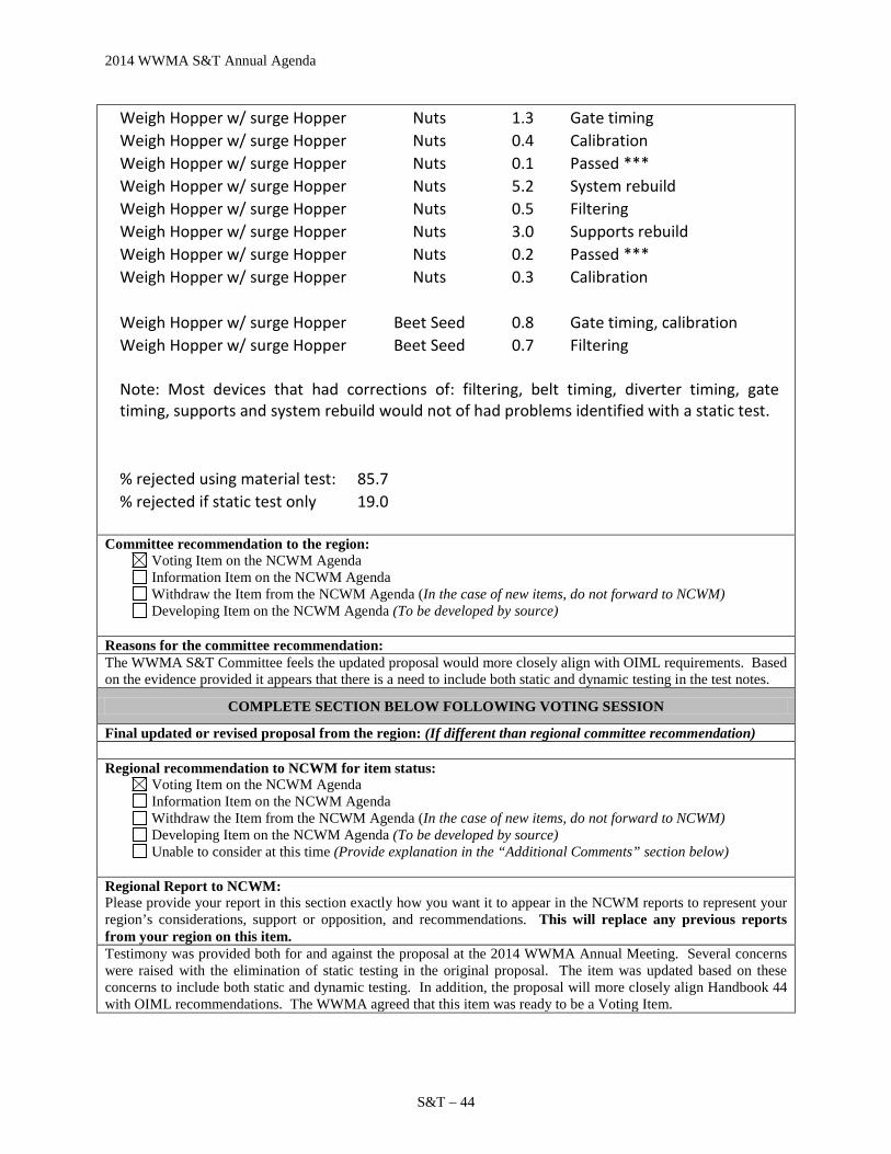
2014 WWMA S&T Annual Agenda
S&T – 44
Weigh Hopper w/ surge Hopper Nuts 1.3 Gate timing Weigh Hopper w/ surge Hopper Nuts 0.4 Calibration Weigh Hopper w/ surge Hopper Nuts 0.1 Passed *** Weigh Hopper w/ surge Hopper Nuts 5.2 System rebuild Weigh Hopper w/ surge Hopper Nuts 0.5 Filtering Weigh Hopper w/ surge Hopper Nuts 3.0 Supports rebuild Weigh Hopper w/ surge Hopper Nuts 0.2 Passed *** Weigh Hopper w/ surge Hopper Nuts 0.3 Calibration
Weigh Hopper w/ surge Hopper Beet Seed 0.8 Gate timing, calibration Weigh Hopper w/ surge Hopper Beet Seed 0.7 Filtering
Note: Most devices that had corrections of: filtering, belt timing, diverter timing, gate timing, supports and system rebuild would not of had problems identified with a static test.
% rejected using material test: 85.7
% rejected if static test only 19.0
Committee recommendation to the region: Voting Item on the NCWM Agenda Information Item on the NCWM Agenda Withdraw the Item from the NCWM Agenda (In the case of new items, do not forward to NCWM) Developing Item on the NCWM Agenda (To be developed by source)
Reasons for the committee recommendation: The WWMA S&T Committee feels the updated proposal would more closely align with OIML requirements. Based on the evidence provided it appears that there is a need to include both static and dynamic testing in the test notes.
COMPLETE SECTION BELOW FOLLOWING VOTING SESSION
Final updated or revised proposal from the region: (If different than regional committee recommendation) Regional recommendation to NCWM for item status:
Voting Item on the NCWM Agenda Information Item on the NCWM Agenda Withdraw the Item from the NCWM Agenda (In the case of new items, do not forward to NCWM) Developing Item on the NCWM Agenda (To be developed by source) Unable to consider at this time (Provide explanation in the “Additional Comments” section below)
Regional Report to NCWM: Please provide your report in this section exactly how you want it to appear in the NCWM reports to represent your region’s considerations, support or opposition, and recommendations. This will replace any previous reports from your region on this item. Testimony was provided both for and against the proposal at the 2014 WWMA Annual Meeting. Several concerns were raised with the elimination of static testing in the original proposal. The item was updated based on these concerns to include both static and dynamic testing. In addition, the proposal will more closely align Handbook 44 with OIML recommendations. The WWMA agreed that this item was ready to be a Voting Item.

2014 WWMA S&T Annual Agenda
S&T –45
330 LIQUID MEASURING DEVICES
330-1 Table S.2.2. Categories of Device and Methods of Sealing (NEW)
Source: Gilbarco, Inc. Purpose: Allow an electronic means to transfer the event logger information for Category 3 event loggers. Item Under Consideration: Amend NIST Handbook 44 Liquid Measuring Devices Code as follows:
Table S.2.2.
Categories of Device and Methods of Sealing
Categories of Device Methods of Sealing
Category 1: No remote configuration capability. Seal by physical seal or two event counters: one for calibration parameters and one for configuration parameters.
Category 2: Remote configuration capability, but access is controlled by physical hardware.
The device shall clearly indicate that it is in the remote configuration mode and record such message if capable of printing in this mode or shall not operate while in this mode.
[The hardware enabling access for remote communication must be on-site. The hardware must be sealed using a physical seal or an event counter for calibration parameters and an event counter for configuration parameters. The event counters may be located either at the individual measuring device or at the system controller; however, an adequate number of counters must be provided to monitor the calibration and configuration parameters of the individual devices at a location. If the counters are located in the system controller rather than at the individual device, means must be provided to generate a hard copy of the information through an on-site device.]*
[*Nonretroactive as of January 1, 1996]

2014 WWMA S&T Annual Agenda
S&T – 46
Category 3: Remote configuration capability access may be unlimited or controlled through a software switch (e.g., password).
[Nonretroactive as of January 1, 1995]
The device shall clearly indicate that it is in the remote configuration mode and record such message if capable of printing in this mode or shall not operate while in this mode.
[Nonretroactive as of January 1, 2001]
An event logger is required in the device; it must include an event counter (000 to 999), the parameter ID, the date and time of the change, and the new value of the parameter. The use of an electronic means such as a thumb drive, flash drive, laptop computer, Email, cell phone may be used to receive the event logger information from a dispenser or another on-site devise. A printed copy of the information must be available through the device or through another on-site device if the device is not equipped to offer an electronic means of supplying the information. The event logger shall have a capacity to retain records equal to 10 times the number of sealable parameters in the device, but not more than 1000 records are required. (Note: Does not require 1000 changes to be stored for each parameter.)
[Nonretroactive as of January 1, 1995] (Table Added 1993) (Amended 1995, 1998, 1999, and 2006)
Background / Discussion: This proposal would recognize the use of an electronic means such as a thumb drive, flash drive, laptop computer, email or cell phone to receive the event logger information from a dispenser or another on-site device. Event logger information in an electronic format is easier to sort and search than the traditional paper format. Paper version of the event logger can not be readily sorted and analyzed like an electronic log. A consideration is that W&Ms officials may not have means to receive the electronic version of the event logger. HB44 allows the use of electronic receipts for consumers. Event loggers could be developed to take advantage of technology to facilitate W&Ms review of event logs.
Item 330-1
Summary of comments considered by the regional committee (in writing or during the open hearings): Gordon Johnson, Gilbarco, and submitter, provided information on this item. He stated that the intent of this proposal was to include the possibility of transferring event data in to an electronic format. Further, this will allow W&M officials and device users to retrieve and sort the information in a more useable form. Item as proposed by the regional committee: (If different than agenda item) Committee recommendation to the region:
Voting Item on the NCWM Agenda Information Item on the NCWM Agenda Withdraw the Item from the NCWM Agenda (In the case of new items, do not forward to NCWM) Developing Item on the NCWM Agenda (To be developed by source)
Reasons for the committee recommendation: The WWMA S&T Committee feels that this item has merit, however, has concerns in regard to the security of the information downloaded and potential for data manipulation. In addition, electronic means may include other methods that are not listed in the table and providing examples may not be appropriate. The Committee also has concerns in regard to what equipment will be necessary for the W&M official to retrieve the event data on-site and in a timely manner.
COMPLETE SECTION BELOW FOLLOWING VOTING SESSION
Final updated or revised proposal from the region: (If different than regional committee recommendation)

2014 WWMA S&T Annual Agenda
S&T –47
Regional recommendation to NCWM for item status:
Voting Item on the NCWM Agenda Information Item on the NCWM Agenda Withdraw the Item from the NCWM Agenda (In the case of new items, do not forward to NCWM) Developing Item on the NCWM Agenda (To be developed by source) Unable to consider at this time (Provide explanation in the “Additional Comments” section below)
Regional Report to NCWM: Please provide your report in this section exactly how you want it to appear in the NCWM reports to represent your region’s considerations, support or opposition, and recommendations. This will replace any previous reports from your region on this item. Testimony was presented by the submitter during the 2014 WWMA Annual Meeting with no opposing opinions being presented. The WWMA S&T Committee felt that the item had merit and would more easily facilitate examination of an audit trail. However, there are some concerns with respect to data security and the transfer of information to W&M officials. Therefore it was agreed that this be a Developing Item to allow the submitter to refine the proposal.
330-2 N.4.1.3. Normal Tests on Wholesale Multi-Point Calibration Devices (NEW)
Source: NCWM Multi-Point Calibration Group
Purpose: Update the Liquid Measuring Device Code to reflect advances in meter calibration technology. Item Under Consideration: Add a new paragraph to the NIST Handbook 44 Liquid Measuring Devices Code as follows:
N.4.1.3. Normal Tests on Wholesale Multi-Point Calibration Devices. – The normal test of a wholesale liquid-measuring device with electronically programmed linearization factors for various flow rates shall be made at the maximum discharge rate developed by the installation. Any additional tests conducted at flow rates down to and including the rated minimum discharge flow rate shall be considered normal tests.
Background / Discussion: New technology makes it possible to use linearization factors to optimize accuracy at every flow rate for which a wholesale meter is programmed to deliver. A special tolerance has traditionally been applied to slow flow tests on wholesale meters with mechanical single-point calibrators because accuracy could only be optimized at one flow rate. A wholesale multi-point calibrated meter does not require a special tolerance at any flow rate since every flow rate can be adjusted as close to zero as practicable. This supports the principle expressed in G-UR.4.3. that adjustments shall be made so as to bring performance errors as close to zero as possible. It also reduces the amount of bias error which startup and shutdown rates introduce into the proving process by reducing performance errors at slow-flow startup and shutdown flow rates. 3. Applies only to meters which are actually configured with multiple calibration points. Meter owners who do not want to take the time to calibrate at multiple flow rates may configure their meters for single point calibration. This allows meters with single point calibration to have a larger tolerance at slow-flow rates than meters with multi-point calibration. Multi-point calibrated devices are increasingly used as commercial meters. The question of whether they should be treated differently than devices with single–point calibration needs to be addressed.

2014 WWMA S&T Annual Agenda
S&T – 48
Item 330-2
Summary of comments considered by the regional committee (in writing or during the open hearings): Doug Deiman, AK, presented a summary of the proposal and indicated the Multi-Point Calibration Group feels the item is sufficiently developed and ready to move forward as a voting item. Item as proposed by the regional committee: (If different than agenda item) Committee recommendation to the region:
Voting Item on the NCWM Agenda Information Item on the NCWM Agenda Withdraw the Item from the NCWM Agenda (In the case of new items, do not forward to NCWM) Developing Item on the NCWM Agenda (To be developed by source)
Reasons for the committee recommendation: The WWMA S&T Committee felt the item was fully developed and ready for a vote. The committee also recommends that items 330-2, 330-3, 331-1, 331-2 and 360-3 should be combined in to one item for the interim agenda.
COMPLETE SECTION BELOW FOLLOWING VOTING SESSION
Final updated or revised proposal from the region: (If different than regional committee recommendation) Regional recommendation to NCWM for item status:
Voting Item on the NCWM Agenda Information Item on the NCWM Agenda Withdraw the Item from the NCWM Agenda (In the case of new items, do not forward to NCWM) Developing Item on the NCWM Agenda (To be developed by source) Unable to consider at this time (Provide explanation in the “Additional Comments” section below)
Regional Report to NCWM: Please provide your report in this section exactly how you want it to appear in the NCWM reports to represent your region’s considerations, support or opposition, and recommendations. This will replace any previous reports from your region on this item. Testimony was presented at the 2014 WWMA Annual Meeting by a member of the Multi-Point Calibration Group, stating that the item is fully developed and ready to be a Voting Item. No opposition was heard during open hearing and the WWMA agreed that the item was sufficiently developed and should be a Voting Item.
330-3 D N.4.2.5. Determination of Error on Wholesale Devices with Multiple Flow Rates and Calibration Factors
Source: Minnesota Weights and Measures Division (2014)
Purpose: To update Handbook 44 to reflect the technological changes in registers for liquid measuring devices and to alert Weights & Measures officials to the fact that error in start-up and shut-down delivery quantities can introduce linear errors in the calibration at normal flow rates; these errors increase the further the delivered quantity deviates from the prover size used at calibration. Item Under Consideration: Add a new paragraph to the NIST Handbook 44 Liquid Measuring Devices Code as follows:
N.4.2.5. Initial Verification
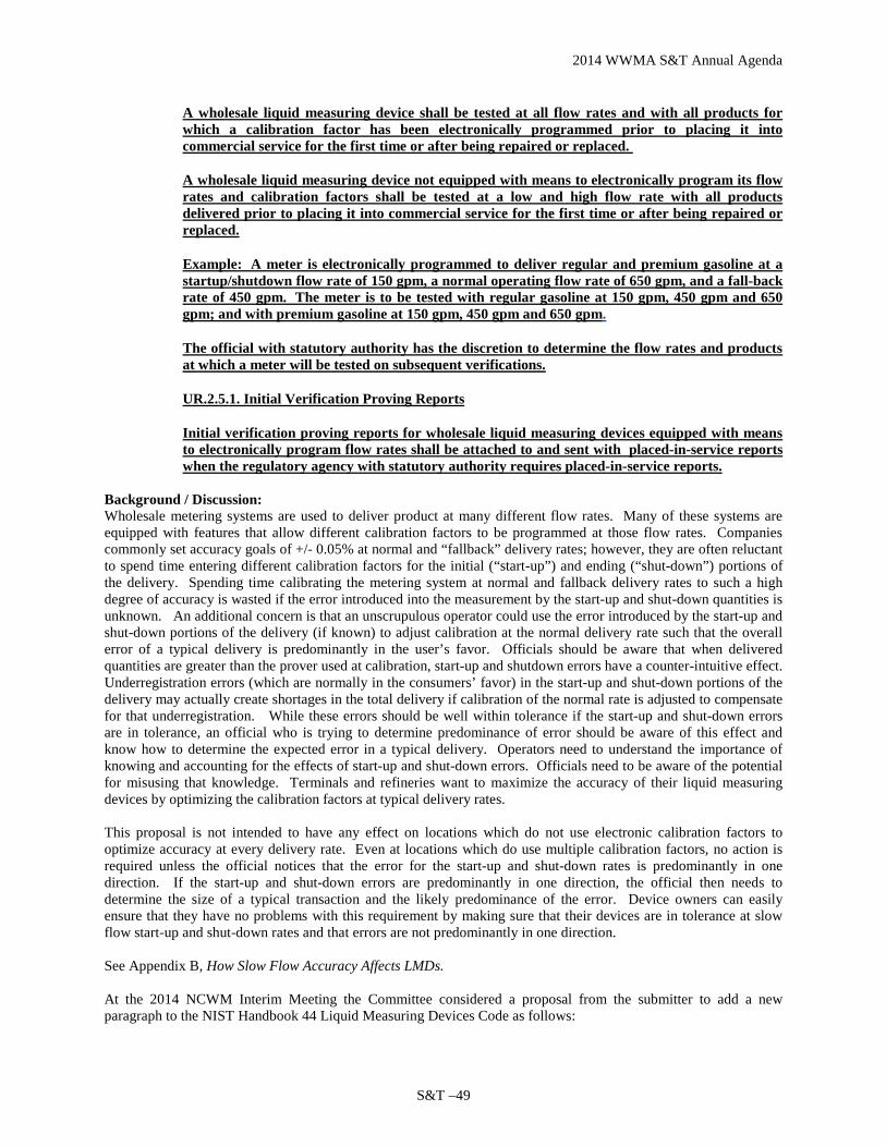
2014 WWMA S&T Annual Agenda
S&T –49
A wholesale liquid measuring device shall be tested at all flow rates and with all products for which a calibration factor has been electronically programmed prior to placing it into commercial service for the first time or after being repaired or replaced.
A wholesale liquid measuring device not equipped with means to electronically program its flow rates and calibration factors shall be tested at a low and high flow rate with all products delivered prior to placing it into commercial service for the first time or after being repaired or replaced.
Example: A meter is electronically programmed to deliver regular and premium gasoline at a startup/shutdown flow rate of 150 gpm, a normal operating flow rate of 650 gpm, and a fall-back rate of 450 gpm. The meter is to be tested with regular gasoline at 150 gpm, 450 gpm and 650 gpm; and with premium gasoline at 150 gpm, 450 gpm and 650 gpm.
The official with statutory authority has the discretion to determine the flow rates and products at which a meter will be tested on subsequent verifications.
UR.2.5.1. Initial Verification Proving Reports
Initial verification proving reports for wholesale liquid measuring devices equipped with means to electronically program flow rates shall be attached to and sent with placed-in-service reports when the regulatory agency with statutory authority requires placed-in-service reports.
Background / Discussion: Wholesale metering systems are used to deliver product at many different flow rates. Many of these systems are equipped with features that allow different calibration factors to be programmed at those flow rates. Companies commonly set accuracy goals of +/- 0.05% at normal and “fallback” delivery rates; however, they are often reluctant to spend time entering different calibration factors for the initial (“start-up”) and ending (“shut-down”) portions of the delivery. Spending time calibrating the metering system at normal and fallback delivery rates to such a high degree of accuracy is wasted if the error introduced into the measurement by the start-up and shut-down quantities is unknown. An additional concern is that an unscrupulous operator could use the error introduced by the start-up and shut-down portions of the delivery (if known) to adjust calibration at the normal delivery rate such that the overall error of a typical delivery is predominantly in the user’s favor. Officials should be aware that when delivered quantities are greater than the prover used at calibration, start-up and shutdown errors have a counter-intuitive effect. Underregistration errors (which are normally in the consumers’ favor) in the start-up and shut-down portions of the delivery may actually create shortages in the total delivery if calibration of the normal rate is adjusted to compensate for that underregistration. While these errors should be well within tolerance if the start-up and shut-down errors are in tolerance, an official who is trying to determine predominance of error should be aware of this effect and know how to determine the expected error in a typical delivery. Operators need to understand the importance of knowing and accounting for the effects of start-up and shut-down errors. Officials need to be aware of the potential for misusing that knowledge. Terminals and refineries want to maximize the accuracy of their liquid measuring devices by optimizing the calibration factors at typical delivery rates. This proposal is not intended to have any effect on locations which do not use electronic calibration factors to optimize accuracy at every delivery rate. Even at locations which do use multiple calibration factors, no action is required unless the official notices that the error for the start-up and shut-down rates is predominantly in one direction. If the start-up and shut-down errors are predominantly in one direction, the official then needs to determine the size of a typical transaction and the likely predominance of the error. Device owners can easily ensure that they have no problems with this requirement by making sure that their devices are in tolerance at slow flow start-up and shut-down rates and that errors are not predominantly in one direction. See Appendix B, How Slow Flow Accuracy Affects LMDs. At the 2014 NCWM Interim Meeting the Committee considered a proposal from the submitter to add a new paragraph to the NIST Handbook 44 Liquid Measuring Devices Code as follows:

2014 WWMA S&T Annual Agenda
S&T – 50
N.4.2.5. Determination of Error on Wholesale Devices with Multiple Flow Rates and Calibration Factors -On wholesale devices which are configured with multiple flow rates where each flow rate has its own calibration factor, and which are programmed to deliver a set quantity at a slow flow rate on start-up and/or shut-down, the effect of start-up and shut-down rates on the accuracy of the typical delivery shall be considered if the typical delivery is greater or less than the test measure used at the time of evaluation. The weights and measures jurisdiction shall determine the size of the typical delivery based upon available evidence.
The Committee acknowledged that, at the heart of this issue is the need to develop guidance for inspectors and service personnel in the proper use and inspection of systems with multiple calibration factors. This work may encompass issues such as how the multiple calibration factor features can be used to adjust meters at different flow rates; to adjust the accuracy of the initial “start-up” and ending “slow-down” portions of a delivery; to adjust the accuracy of a meter when delivering different product types, etc. During its Open Hearings, the Committee heard questions from Mr. Henry Oppermann (Weights and Measures Consulting) and from Mrs. Tina Butcher (NIST OWM) who questioned how an inspector would analyze the results without conducting accuracy tests at the slower flow rates. Ms. Julie Quinn (MN), the submitter of this proposal, clarified that, in order to apply the proposed “Note,” an inspector must run tests at these flow rates to be able to determine the magnitude and direction of the error. Ms. Juana Williams raised some additional questions and noted some comments from NIST OWM (extracted from OWM’s analysis provided to the S&T Committee), including the following.
• How is an inspector to assess the “start-up” and “slow-down” portions of the delivery given that they
include quantities delivered at multiple different flow rates and the actual delivery sizes may vary? • The minimum test draft size requirements may need to be considered and possibly revised to address
tests of these systems. • Caution should be used before making any sort of assessment without conducting any “slow flow”
testing as outlined in the example (which assumes that no “slow flow” test was conducted). • Percentage-based tolerances account and allow for different errors at different delivery sizes. • If the concern centers on the “start-up” and “slow-down” portions of the delivery, the proposal may
need to provide more specific guidance in this regard. Mr. Constantine Cotsoradis (Flint Hills Resources) recognized the validity of the issue and expressed support for proposals that recognize changing technology, but he also acknowledged the questions that were raised within the regionals and at the Interim Meeting needing to be addressed. Ms. Quinn clarified the purpose of the item and the circumstances leading to the proposal, noting that she was unable to attend other regional meetings to provide further explanations of this proposal. She noted that, at one time, the amount of product and the flow rate for the start-up and shut-down portions of a delivery were manually controlled. Today’s systems tend to use automated, programmed values for these portions of the delivery. Ms. Quinn noted that, frequently, companies are reluctant to spend additional time validating the calibration factors used in the start-up and shut-down portions of the delivery. The “typical delivery” sizes would be determined from examining records at the terminal. The intent of the proposal is to raise awareness of the need for the inspector to consider the effects of these portions of the delivery on its overall accuracy. After hearing comments during the Open Hearings and discussing the item further in its work sessions, the Committee agreed to designate this as a Developing Item. The Committee believes that, at least initially, work needs to be focused on the development of guidelines and test procedures that could be incorporated into examination procedure outlines. Ms. Quinn agreed to serve as the contact point for the item. The Committee asks that others interested in this work contact Ms. Quinn. The Committee looks forward to updates on this work as it progresses.

2014 WWMA S&T Annual Agenda
S&T –51
At the 2014 Annual Meeting, the Committee heard comments from Ms. Juana Williams (NIST OWM) who commented that, like the S&T Committee, OWM believes that the existing language in the Liquid-Measuring Devices Code allows for any additional testing that is within the usual and customary use of the system and that develops the operating characteristics of that system, and also believes the work should focus on the development of guidelines and test procedures. OWM looks forward to continued collaboration with the group developing this issue. The Committee also heard an update from Ms. Julie Quinn (MN), the submitter of this item. Ms. Quinn reported that a group of interested parties has been collaborating on this issue since January 2014. During the NCWM Annual Meeting this group met and developed suggested language to address the concerns outlined in this item. Ms. Quinn asked that the Committee include the suggested language in this item for further review and comments by the regional associations and others in the fall. The Committee agreed to maintain this item on its agenda to allow for additional development and input as requested by Ms. Quinn and to replace the original recommendation with the revised language provided by Ms. Quinn as shown in the “Item Under Consideration” above.
Regional Association Comments: WWMA did not forward this item to NCWM, because the language is vague and offers no clear solution. SWMA received comments in Open Hearings and the SWMA S&T Committee’s Work Session indicating a strong concern with the wording “typical delivery.” The SWMA recommended the item be withdrawn based upon lack of merit. The SWMA did not forward this item to NCWM. NEWMA recommends this item be withdrawn for lack of merit because the handbook already establishes a tolerance that applies to the full device test from start up to shut down and applying a tolerance to just start up or shut down could have a significant effect on test results. CWMA supported this item as a Developing Item.
Item 330-3
Summary of comments considered by the regional committee (in writing or during the open hearings): Doug Deiman, AK, presented a summary of the proposal and indicated the Multi-Point Calibration Group feels the item is sufficiently developed and ready to move forward as a voting item. Doug Deiman provided the amended language to addressed the concerns expressed in the open hearings. Item as proposed by the regional committee: (If different than agenda item)
N.4.1.3.N.4.2.5. Initial Verification
(a) A wholesale liquid measuring device shall be tested at all flow rates and with all products for which a calibration linearization factor has been electronically programmed prior to placing it into commercial service for the first time or after being repaired or replaced.
(b) A wholesale liquid measuring device not equipped with means to electronically program its flow rates and calibration linearization factors shall be tested at a low and high flow rate with all products delivered prior to placing it into commercial service for the first time or after being repaired or replaced.
Example: A meter is electronically programmed to deliver regular and premium gasoline at a startup/shutdown flow rate of 150 gpm, a normal operating flow rate of 650 gpm, and a fall-back rate of 450 gpm. The meter is to be tested with regular gasoline at 150 gpm, 450 gpm and 650 gpm; and with premium gasoline at 150 gpm, 450 gpm and 650 gpm.
The official with statutory authority has the discretion to determine the flow rates and products at which a meter will be tested on subsequent verifications.
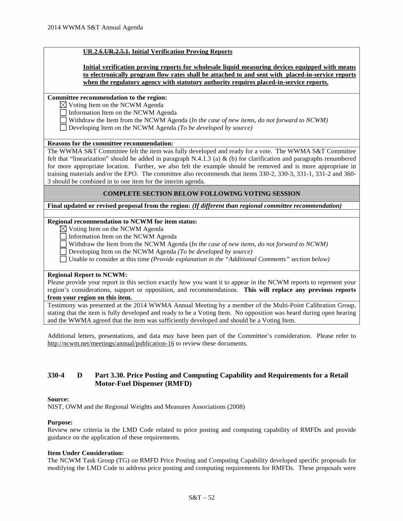
2014 WWMA S&T Annual Agenda
S&T – 52
UR.2.6.UR.2.5.1. Initial Verification Proving Reports
Initial verification proving reports for wholesale liquid measuring devices equipped with means to electronically program flow rates shall be attached to and sent with placed-in-service reports when the regulatory agency with statutory authority requires placed-in-service reports.
Committee recommendation to the region:
Voting Item on the NCWM Agenda Information Item on the NCWM Agenda Withdraw the Item from the NCWM Agenda (In the case of new items, do not forward to NCWM) Developing Item on the NCWM Agenda (To be developed by source)
Reasons for the committee recommendation: The WWMA S&T Committee felt the item was fully developed and ready for a vote. The WWMA S&T Committee felt that “linearization” should be added in paragraph N.4.1.3 (a) & (b) for clarification and paragraphs renumbered for more appropriate location. Further, we also felt the example should be removed and is more appropriate in training materials and/or the EPO. The committee also recommends that items 330-2, 330-3, 331-1, 331-2 and 360-3 should be combined in to one item for the interim agenda.
COMPLETE SECTION BELOW FOLLOWING VOTING SESSION
Final updated or revised proposal from the region: (If different than regional committee recommendation) Regional recommendation to NCWM for item status:
Voting Item on the NCWM Agenda Information Item on the NCWM Agenda Withdraw the Item from the NCWM Agenda (In the case of new items, do not forward to NCWM) Developing Item on the NCWM Agenda (To be developed by source) Unable to consider at this time (Provide explanation in the “Additional Comments” section below)
Regional Report to NCWM: Please provide your report in this section exactly how you want it to appear in the NCWM reports to represent your region’s considerations, support or opposition, and recommendations. This will replace any previous reports from your region on this item. Testimony was presented at the 2014 WWMA Annual Meeting by a member of the Multi-Point Calibration Group, stating that the item is fully developed and ready to be a Voting Item. No opposition was heard during open hearing and the WWMA agreed that the item was sufficiently developed and should be a Voting Item. Additional letters, presentations, and data may have been part of the Committee’s consideration. Please refer to http://ncwm.net/meetings/annual/publication-16 to review these documents.
330-4 D Part 3.30. Price Posting and Computing Capability and Requirements for a Retail Motor-Fuel Dispenser (RMFD)
Source: NIST, OWM and the Regional Weights and Measures Associations (2008)
Purpose: Review new criteria in the LMD Code related to price posting and computing capability of RMFDs and provide guidance on the application of these requirements.
Item Under Consideration: The NCWM Task Group (TG) on RMFD Price Posting and Computing Capability developed specific proposals for modifying the LMD Code to address price posting and computing requirements for RMFDs. These proposals were

2014 WWMA S&T Annual Agenda
S&T –53
adopted by the NCWM in 2012 and published in the 2013 NIST Handbook 44; they are being revisited at the request of the NCWM S&T Committee who has asked the Task Group to complete its review of sample receipts and provide guidance on applying the new criteria. This Item, 360-3, is being retained as a Developing Item pending any additional assignments that may be given by the Committee to the Task Group relative to the implementation of new code requirements that may be adopted. Comments or inquiries may be directed to NIST Technical Advisor, Ms. Juana Williams, at (301) 975-3989 or [email protected].
Background / Discussion: In the early 1990s, various sections of the LMD Code in NIST Handbook 44 were modified to address multi-tier pricing applications in instances where the same product is offered at different unit prices based on the method of payment (such as cash or credit) or other conditions of the sale. Since that time, marketing practices have evolved to include the addition of new practices, such as frequent shopper discounts and club member discounts. Numerous questions have been posed to NIST OWM and weights and measures officials regarding the requirements for posting unit prices, calculation of total price, customer-operated controls, and other related topics, such as definitions for associated terminology. In 2010, the Committee established a task group to further develop this issue. The Task Group proposed a number of changes to the LMD Code to address these issues and those changes were adopted in July 2012.
Additional details on this item can be found in the Committee’s 2008-2012 Final Reports.
During the 2013 NCWM Interim Meeting Open Hearings, the Committee heard a suggestion from Ms. Elson-Houston, speaking as Chair of the Task Group on RMFD Price Posting and Computing Capability on a TG proposal, to further modify paragraph UR.3.3. Computing Device. Ms. Elson-Houston reported that the TG had met and agreed: (1) to develop sample receipts for transactions where motor fuel pricing is discounted after the delivery; (2) the Chair would provide input on the “Do’s and Don’ts” for complying with the requirements that went into effect January 2013 for posting on The Oil Express web newsletter; and (3) to recommend additional amendments to paragraph UR.3.3., which were provided to the Committee. The Committee established a new “Informational” item (See Item 330-4 on the Committee’s 2014 Agenda) to address those modifications and agreed to retain Developing Item 360-3 while the TG continues work to develop guidelines and examples on how the changes made last year to the LMD Code will apply to receipts for post-delivery discounted transactions. On the 2013 NCWM Online Position Forum, one Government representative indicated support for this item with no additional comments. At the 2013 NCWM Annual Meeting, the Committee heard comments from Juana Williams (NIST OWM) who emphasized the importance of continuing to develop guidelines and information to assist regulatory officials and industry in interpreting and applying requirements relative to pre- and post-delivery discounts. NIST OWM is working on the development of guidelines and examples that could be included in NIST EPOs and training materials and has already received positive feedback from members of the Task Group on the examples developed thus far. This information may also be of use to NTEP in the further development of checklist criteria for inclusion in NCWM Publication 14. OWM will continue to develop this information and make it available in updates to EPOs and course materials and would appreciate additional input from the community. Ms. Beth Treseder (API) indicated that API and others within industry would appreciate copies of acceptable receipts as they become available.
The Committee believes that additional work is needed to develop examples and information that will enable consistent and uniform application of the requirements adopted in 2012 and encourages OWM’s continued work on such examples. The Committee asks that the Task Group continue its work by developing and providing additional examples of acceptable receipts to assist regulatory officials and industry in interpreting and applying these requirements. The Committee believes that examples of receipts from deliveries that include both pre- and post-delivery discounts in a single transaction are needed. At the 2014 NCWM Interim Meeting Ms. Fran Elson-Houston (Ohio) spoke as Chair of the RMFD Price Posting and Computing Capability Task Group regarding a meeting of the TG, which occurred at the 2014 Interim Meeting. Ms. Elson-Houston advised the Committee that she will work with NIST to develop additional examples of receipts
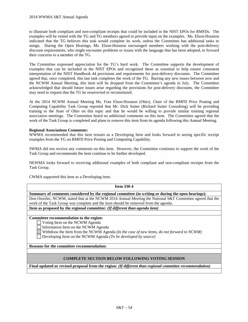
2014 WWMA S&T Annual Agenda
S&T – 54
to illustrate both compliant and non-compliant receipts that could be included in the NIST EPOs for RMFDs. The examples will be vetted with the TG and TG members agreed to provide input on the examples. Ms. Elson-Houston indicated that the TG believes this task would complete its work, unless the Committee has additional tasks to assign. During the Open Hearings, Ms. Elson-Houston encouraged members working with the post-delivery discount requirements, who might encounter problems or issues with the language that has been adopted, to forward their concerns to a member of the TG. The Committee expressed appreciation for the TG’s hard work. The Committee supports the development of examples that can be included in the NIST EPOs and recognized these as essential to help ensure consistent interpretation of the NIST Handbook 44 provisions and requirements for post-delivery discounts. The Committee agreed that, once completed, this last task completes the work of the TG. Barring any new issues between now and the NCWM Annual Meeting, this item will be dropped from the Committee’s agenda in July. The Committee acknowledged that should future issues arise regarding the provisions for post-delivery discounts, the Committee may need to request that the TG be resurrected or reconstituted. At the 2014 NCWM Annual Meeting Ms. Fran Elson-Houston (Ohio), Chair of the RMFD Price Posting and Computing Capability Task Group reported that Mr. Dick Suiter (Richard Suiter Consulting) will be providing training to the State of Ohio on this topic and that he would be willing to provide similar training regional association meetings. The Committee heard no additional comments on this item. The Committee agreed that the work of the Task Group is completed and plans to remove this item from its agenda following this Annual Meeting.
Regional Associations Comments: WWMA recommended that this item remain as a Developing Item and looks forward to seeing specific receipt examples from the TG on RMFD Price Posting and Computing Capability. SWMA did not receive any comments on this item. However, the Committee continues to support the work of the Task Group and recommends the item continue to be further developed. NEWMA looks forward to receiving additional examples of both compliant and non-compliant receipts from the Task Group. CWMA supported this item as a Developing item.
Item 330-4
Summary of comments considered by the regional committee (in writing or during the open hearings): Don Onwiler, NCWM, stated that at the NCWM 2014 Annual Meeting the National S&T Committee agreed that the work of the Task Group was complete and the item should be removed from the agenda. Item as proposed by the regional committee: (If different than agenda item) Committee recommendation to the region:
Voting Item on the NCWM Agenda Information Item on the NCWM Agenda Withdraw the Item from the NCWM Agenda (In the case of new items, do not forward to NCWM) Developing Item on the NCWM Agenda (To be developed by source)
Reasons for the committee recommendation:
COMPLETE SECTION BELOW FOLLOWING VOTING SESSION
Final updated or revised proposal from the region: (If different than regional committee recommendation)
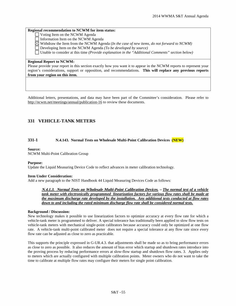
2014 WWMA S&T Annual Agenda
S&T –55
Regional recommendation to NCWM for item status: Voting Item on the NCWM Agenda Information Item on the NCWM Agenda Withdraw the Item from the NCWM Agenda (In the case of new items, do not forward to NCWM) Developing Item on the NCWM Agenda (To be developed by source) Unable to consider at this time (Provide explanation in the “Additional Comments” section below)
Regional Report to NCWM: Please provide your report in this section exactly how you want it to appear in the NCWM reports to represent your region’s considerations, support or opposition, and recommendations. This will replace any previous reports from your region on this item.
Additional letters, presentations, and data may have been part of the Committee’s consideration. Please refer to http://ncwm.net/meetings/annual/publication-16 to review these documents.
331 VEHICLE-TANK METERS
331-1 N.4.143. Normal Tests on Wholesale Multi-Point Calibration Devices (NEW)
Source: NCWM Multi-Point Calibration Group
Purpose: Update the Liquid Measuring Device Code to reflect advances in meter calibration technology. Item Under Consideration: Add a new paragraph to the NIST Handbook 44 Liquid Measuring Devices Code as follows:
N.4.1.3. Normal Tests on Wholesale Multi-Point Calibration Devices. – The normal test of a vehicle tank meter with electronically programmed linearization factors for various flow rates shall be made at the maximum discharge rate developed by the installation. Any additional tests conducted at flow rates down to and including the rated minimum discharge flow rate shall be considered normal tests.
Background / Discussion: New technology makes it possible to use linearization factors to optimize accuracy at every flow rate for which a vehicle-tank meter is programmed to deliver. A special tolerance has traditionally been applied to slow flow tests on vehicle-tank meters with mechanical single-point calibrators because accuracy could only be optimized at one flow rate. A vehicle-tank multi-point calibrated meter does not require a special tolerance at any flow rate since every flow rate can be adjusted as close to zero as practicable. This supports the principle expressed in G-UR.4.3. that adjustments shall be made so as to bring performance errors as close to zero as possible. It also reduces the amount of bias error which startup and shutdown rates introduce into the proving process by reducing performance errors at slow-flow startup and shutdown flow rates. 3. Applies only to meters which are actually configured with multiple calibration points. Meter owners who do not want to take the time to calibrate at multiple flow rates may configure their meters for single point calibration.
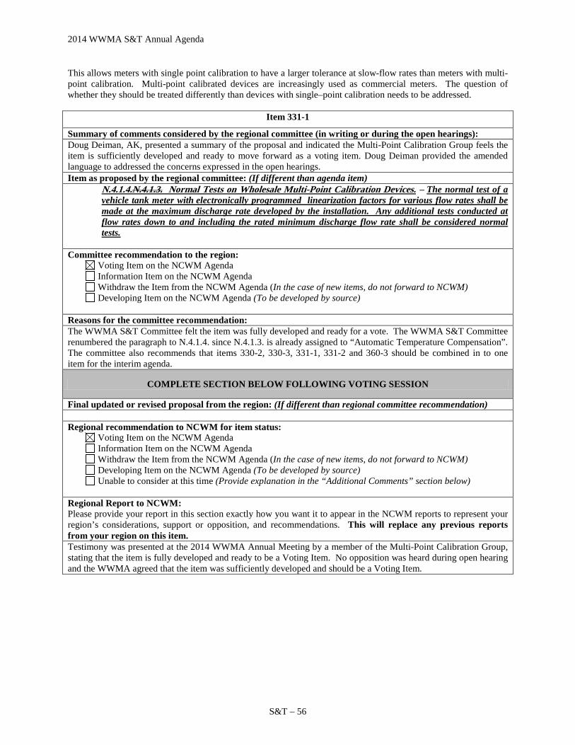
2014 WWMA S&T Annual Agenda
S&T – 56
This allows meters with single point calibration to have a larger tolerance at slow-flow rates than meters with multi-point calibration. Multi-point calibrated devices are increasingly used as commercial meters. The question of whether they should be treated differently than devices with single–point calibration needs to be addressed.
Item 331-1
Summary of comments considered by the regional committee (in writing or during the open hearings): Doug Deiman, AK, presented a summary of the proposal and indicated the Multi-Point Calibration Group feels the item is sufficiently developed and ready to move forward as a voting item. Doug Deiman provided the amended language to addressed the concerns expressed in the open hearings. Item as proposed by the regional committee: (If different than agenda item)
N.4.1.4.N.4.1.3. Normal Tests on Wholesale Multi-Point Calibration Devices. – The normal test of a vehicle tank meter with electronically programmed linearization factors for various flow rates shall be made at the maximum discharge rate developed by the installation. Any additional tests conducted at flow rates down to and including the rated minimum discharge flow rate shall be considered normal tests.
Committee recommendation to the region:
Voting Item on the NCWM Agenda Information Item on the NCWM Agenda Withdraw the Item from the NCWM Agenda (In the case of new items, do not forward to NCWM) Developing Item on the NCWM Agenda (To be developed by source)
Reasons for the committee recommendation: The WWMA S&T Committee felt the item was fully developed and ready for a vote. The WWMA S&T Committee renumbered the paragraph to N.4.1.4. since N.4.1.3. is already assigned to “Automatic Temperature Compensation”. The committee also recommends that items 330-2, 330-3, 331-1, 331-2 and 360-3 should be combined in to one item for the interim agenda.
COMPLETE SECTION BELOW FOLLOWING VOTING SESSION
Final updated or revised proposal from the region: (If different than regional committee recommendation) Regional recommendation to NCWM for item status:
Voting Item on the NCWM Agenda Information Item on the NCWM Agenda Withdraw the Item from the NCWM Agenda (In the case of new items, do not forward to NCWM) Developing Item on the NCWM Agenda (To be developed by source) Unable to consider at this time (Provide explanation in the “Additional Comments” section below)
Regional Report to NCWM: Please provide your report in this section exactly how you want it to appear in the NCWM reports to represent your region’s considerations, support or opposition, and recommendations. This will replace any previous reports from your region on this item. Testimony was presented at the 2014 WWMA Annual Meeting by a member of the Multi-Point Calibration Group, stating that the item is fully developed and ready to be a Voting Item. No opposition was heard during open hearing and the WWMA agreed that the item was sufficiently developed and should be a Voting Item.

2014 WWMA S&T Annual Agenda
S&T –57
331-2 D N.4.2.1. Determination of Error on Vehicle-Tank Meters with Multiple Flow Rates and Calibration Factors
Source: Minnesota Weights and Measures Division (2014)
Purpose: To update NIST Handbook 44 to reflect the technological changes in registers for vehicle-tank meters and to alert Weights & Measures officials to the fact that error in start-up and shut-down delivery quantities can introduce linear errors in the calibration at normal flow rates which increase the further the delivered quantity deviates from the prover size used at calibration. Item Under Consideration: Amend NIST Handbook 44 Vehicle Tank Meter Code as follows:
N.4.6. Initial Verification
A vehicle tank meter shall be tested at all flow rates and with all products for which a calibration factor has been electronically programmed prior to placing it into commercial service for the first time or after being repaired or replaced.
A vehicle tank meter not equipped with means to electronically program its flow rates and calibration factors shall be tested at a low and high flow rate with all products delivered prior to placing it into commercial service for the first time or after being repaired or replaced.
Example: A vehicle tank meter is electronically programmed to deliver regular and premium gasoline at a startup/shutdown flow rate of 20 gpm, a normal operating flow rate of 100 gpm, and an intermediate rate of 65 gpm. The meter is to be tested with regular gasoline at 20 gpm, 65 gpm and 100 gpm; and with premium gasoline at 20 gpm, 65 gpm and 100 gpm.
The official with statutory authority has the discretion to determine the flow rates and products at which a vehicle tank meter will be tested on subsequent verifications.
UR.1.5. Initial Verification Proving Reports
Initial verification proving reports for vehicle tank meters equipped with means to electronically program flow rates shall be attached to and sent with placed-in-service reports when the regulatory agency with statutory authority requires placed-in-service reports.
Background / Discussion: Many terminals and refineries want to maximize the accuracy of their liquid-measuring devices by optimizing the calibration factors at typical delivery speeds and some bulk delivery companies are beginning to utilize the capabilities of electronic registers with multiple calibration factors to optimize their accuracy at flow rates that are customarily used. Just like registers on wholesale liquid measuring devices, these meters can be configured for a standard initial “start-up” and ending “shut-down” quantity delivered at a slower speed than is used for the remainder of the delivery. Service agents are expected to calibrate devices as close to zero as possible, but spending time calibrating normal delivery rates to a high degree of accuracy is wasted if the error introduced into the measurement by the start-up and shut-down quantities is unknown. On the other hand, an unscrupulous operator could also use the known error introduced by the start-up and shut-down errors to calibrate the normal delivery rates so that all the errors on typical deliveries work predominantly in the user’s favor. Officials should be aware that when delivered quantities are greater than the prover used at calibration, start-up and shut-down errors have a counter-intuitive effect. Underregistration, which normally operates in the consumers’ favor, may actually create shortages in the total delivery if calibration of the normal rate was adjusted to compensate for that underregistration. While these errors should be well within tolerance if the start-up and shut-down error are in tolerance, an official who is trying to determine predominance of error should be aware of this effect and know how to calculate the

2014 WWMA S&T Annual Agenda
S&T – 58
expected error in a typical delivery. Operators need to understand the importance of knowing and accounting for the effects of start-up and shut-down errors. Officials need to be aware of the potential for misusing that knowledge. This proposal has no effect on locations which do not use electronic calibration factors to optimize accuracy at every delivery rate. Even at locations which do, no action is required unless the official notices that the error for the start-up and shut-down rates is predominantly in one direction. If the start-up and shut-down errors are predominantly in one direction, the official then needs to determine the size of a typical transaction and the likely predominance of the error. Device owners can easily ensure that they have no problems with this requirement by making sure that their devices are in tolerance at the slower start-up and shut-down flow rates and errors are not predominantly one way or the other. See Appendix C, How Slow Flow Errors Affect VTMs. See comments Item 330-4 for details of comments from the 2014 NCWM Interim Meeting. At the 2014 NCWM Interim Meeting the Committee considered a proposal from the submitter to amend NIST Handbook 44 Vehicle Tank Meter Code as follows:
N.4.2.1. Determination of Error on Vehicle-Tank Meters with Multiple Flow Rates and Calibration Factors -On vehicle tank meters which are configured with multiple flow rates where each flow rate has its own calibration factor, and which are programmed to deliver a set quantity at a slow flow rate on start-up and/or shut-down, the effect of start-up and shut-down rates on the accuracy of the typical delivery shall be considered if the typical delivery is greater or less than the test measure used at the time of evaluation. The weights and measures jurisdiction shall determine the size of the typical delivery based upon available evidence.
After hearing comments during the Open Hearings and discussing the item further in its work sessions, the Committee agreed to designate this as a Developing Item. The Committee believes that, at least initially, work needs to be focused on the development of guidelines and test procedures that could be incorporated into examination procedure outlines. The Committee Chairman noted that the submitter, Ms. Julie Quinn (MN), agreed to serve as the contact point for the item, and will be working with others to further develop guidelines for systems with multiple-point calibration capability. Ms. Quinn thanked those who have offered to help and noted that, although the specific issue presented to the Committee dealt with predominance of errors in certain portions of the delivery, she agreed that the issue is really dealing with metering systems with multiple-point calibration capability. The Committee asks that others interested in this work contact Ms. Quinn. The Committee looks forward to updates on this work as it progresses. At the 2014 Annual Meeting, the Committee heard comments from Ms. Juana Williams (NIST OWM) who commented that, like the S&T Committee, OWM believes that the existing language in the Vehicle-Tank Meters Code allows for any additional testing that is within the usual and customary use of the system and that develops the operating characteristics of that system, and also believes the work should focus on the development of guidelines and test procedures. OWM looks forward to continued collaboration with the group developing this issue. The Committee also heard an update from Ms. Julie Quinn (MN), the submitter of this item. Ms. Quinn reported that a group of interested parties has been collaborating on this issue since January 2014. During the NCWM Annual Meeting this group met and developed suggested language to address the concerns outlined in this item. Ms. Quinn asked that the Committee include the suggested language in this item for further review and comments by the regional associations and others in the fall. The Committee agreed to maintain this item on its agenda to allow for additional development and input as requested by Ms. Quinn and to replace the original recommendation with the revised language provided by Ms. Quinn as shown in the “Item Under Consideration” above.
Regional Association Comments: WWMA agrees the proposed language is confusing and no support for this item was conveyed. The WWMA agrees the language in the proposal is vague and offers no clear solution. The WWMA did not forward the item to NCWM.

2014 WWMA S&T Annual Agenda
S&T –59
SWMA again heard comments concerning the wording “typical delivery.” Based on comments received in Open Hearings and the SWMA S&T Committee’s Work Session, the SWMA agreed to withdraw based on lack of merit. SWMA did not forward this item to NCWM. NEWMA revisited their position on this item from the 2013 Interim meeting, in turn recommends this item be withdrawn for lack of merit because Handbook 44 already establishes a tolerance that applies to the full device test from start up to shut down and applying a tolerance to just start up or shut down could have a significant effect on test results. CWMA supported this item as a Developing item.
Item 331-2
Summary of comments considered by the regional committee (in writing or during the open hearings): Doug Deiman, AK, presented a summary of the proposal and indicated the Multi-Point Calibration Group feels the item is sufficiently developed and ready to move forward as a voting item. Item as proposed by the regional committee: (If different than agenda item)
N.4.6. Initial Verification
(a) A vehicle tank meter shall be tested at all flow rates and with all products for which a calibration linearization factor has been electronically programmed prior to placing it into commercial service for the first time or after being repaired or replaced.
(b) A vehicle tank meter not equipped with means to electronically program its flow rates and calibration linearization factors shall be tested at a low and high flow rate with all products delivered prior to placing it into commercial service for the first time or after being repaired or replaced.
Example: A vehicle tank meter is electronically programmed to deliver regular and premium gasoline at a startup/shutdown flow rate of 20 gpm, a normal operating flow rate of 100 gpm, and an intermediate rate of 65 gpm. The meter is to be tested with regular gasoline at 20 gpm, 65 gpm and 100 gpm; and with premium gasoline at 20 gpm, 65 gpm and 100 gpm.
The official with statutory authority has the discretion to determine the flow rates and products at which a vehicle tank meter will be tested on subsequent verifications.
UR.1.5. Initial Verification Proving Reports
Initial verification proving reports for vehicle tank meters equipped with means to electronically program flow rates shall be attached to and sent with placed-in-service reports when the regulatory agency with statutory authority requires placed-in-service reports.
Committee recommendation to the region:
Voting Item on the NCWM Agenda Information Item on the NCWM Agenda Withdraw the Item from the NCWM Agenda (In the case of new items, do not forward to NCWM) Developing Item on the NCWM Agenda (To be developed by source)
Reasons for the committee recommendation: The WWMA S&T Committee felt the item was fully developed and ready for a vote. The WWMA S&T Committee felt that “linearization” should be added for clarification in paragraph N.4.6 (a) & (b). Further, the example should be removed and is more appropriate in training materials and/or the EPO. The committee also recommends that items 330-2, 330-3, 331-1, 331-2 and 360-3 should be combined in to one item for the interim agenda.
COMPLETE SECTION BELOW FOLLOWING VOTING SESSION
Final updated or revised proposal from the region: (If different than regional committee recommendation)
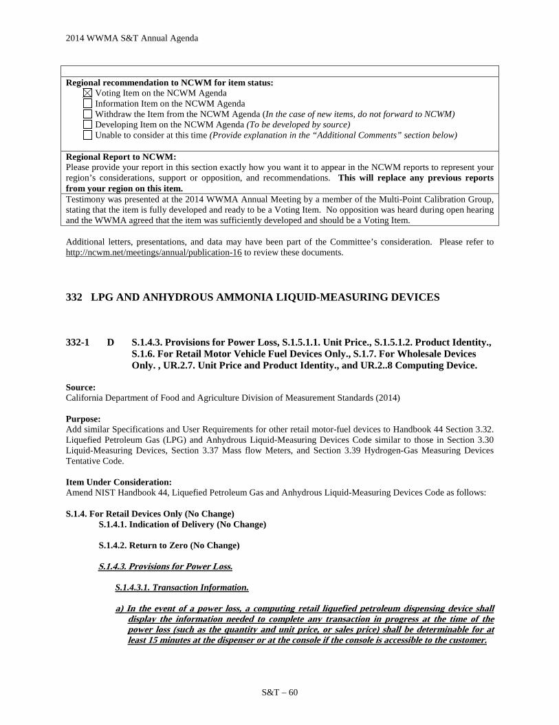
2014 WWMA S&T Annual Agenda
S&T – 60
Regional recommendation to NCWM for item status:
Voting Item on the NCWM Agenda Information Item on the NCWM Agenda Withdraw the Item from the NCWM Agenda (In the case of new items, do not forward to NCWM) Developing Item on the NCWM Agenda (To be developed by source) Unable to consider at this time (Provide explanation in the “Additional Comments” section below)
Regional Report to NCWM: Please provide your report in this section exactly how you want it to appear in the NCWM reports to represent your region’s considerations, support or opposition, and recommendations. This will replace any previous reports from your region on this item. Testimony was presented at the 2014 WWMA Annual Meeting by a member of the Multi-Point Calibration Group, stating that the item is fully developed and ready to be a Voting Item. No opposition was heard during open hearing and the WWMA agreed that the item was sufficiently developed and should be a Voting Item. Additional letters, presentations, and data may have been part of the Committee’s consideration. Please refer to http://ncwm.net/meetings/annual/publication-16 to review these documents.
332 LPG AND ANHYDROUS AMMONIA LIQUID-MEASURING DEVICES
332-1 D S.1.4.3. Provisions for Power Loss, S.1.5.1.1. Unit Price., S.1.5.1.2. Product Identity., S.1.6. For Retail Motor Vehicle Fuel Devices Only., S.1.7. For Wholesale Devices Only. , UR.2.7. Unit Price and Product Identity., and UR.2..8 Computing Device.
Source: California Department of Food and Agriculture Division of Measurement Standards (2014) Purpose: Add similar Specifications and User Requirements for other retail motor-fuel devices to Handbook 44 Section 3.32. Liquefied Petroleum Gas (LPG) and Anhydrous Liquid-Measuring Devices Code similar to those in Section 3.30 Liquid-Measuring Devices, Section 3.37 Mass flow Meters, and Section 3.39 Hydrogen-Gas Measuring Devices Tentative Code. Item Under Consideration: Amend NIST Handbook 44, Liquefied Petroleum Gas and Anhydrous Liquid-Measuring Devices Code as follows: S.1.4. For Retail Devices Only (No Change) S.1.4.1. Indication of Delivery (No Change) S.1.4.2. Return to Zero (No Change)
S.1.4.3. Provisions for Power Loss.
S.1.4.3.1. Transaction Information.
a) In the event of a power loss, a computing retail liquefied petroleum dispensing device shall display the information needed to complete any transaction in progress at the time of the power loss (such as the quantity and unit price, or sales price) shall be determinable for at least 15 minutes at the dispenser or at the console if the console is accessible to the customer.

2014 WWMA S&T Annual Agenda
S&T –61
b) In the event of a power loss, both an electronic digital retail non-computing stationary liquefied petroleum gas dispenser and a vehicle-mounted electronic digital liquefied petroleum gas dispenser shall display the information needed to complete any transaction in progress at the time of the power loss.
S 1.4.3.2. User Information. – The device memory shall retain information on the quantity of fuel dispensed and the sales price totals during power loss.
S.1.5. For Stationary Retail Devices Only.
S.1.5.1. Display of Unit Price and Product Identity. – In a device of the computing type, means shall be provided for displaying on each face of the device the unit price at which the device is set to compute or to deliver as the case may be, and there shall be conspicuously displayed on each side of the device the identity of the product that is being dispensed. If a device is so designed as to dispense more than one grade, brand, blend, or mixture of product, the identity of the grade, brand, blend, or mixture being dispensed shall also be displayed on each face of the device.
S.1.5.1.1. Unit Price.
(a) A computing or money-operated device shall be able to display on each face the unit price at which the device is set to compute or to dispense.
(b) Except for dispensers used exclusively for fleet sales, other price contract sales, and truck refueling (e.g., truck stop dispensers used only to refuel trucks), whenever a grade, brand, blend, or mixture is offered for sale from a device at more than one unit price, then all of the unit prices at which that product is offered for sale shall meet the following conditions: (1) For a system that applies a discount prior to the delivery, all unit prices shall be
displayed or shall be capable of being displayed on the dispenser through a deliberate action of the purchaser prior to the delivery of the product. It is not necessary that all of the unit prices for all grades, brands, blends, or mixtures be simultaneously displayed prior to the delivery of the product.
(2) For a system that offers post-delivery discounts on fuel sales, display of pre-delivery
unit price information is exempt from (b)(1), provided the system complies with S.1.6.8. Recorded Representations for Transactions Where a Post-Delivery Discount(s) is Provided.
Note: When a product is offered at more than one unit price, display of the unit price information may be through the deliberate action of the purchaser: 1) using controls on the device; 2) through the purchaser’s use of personal or vehicle-mounted electronic equipment communicating with the system; or 3) verbal instructions by the customer.
S.1.5.1.2. Product Identity.
(a) A device shall be able to conspicuously display on each side the identity of the product
being dispensed.
(b) A device designed to dispense more than one grade, brand, blend, or mixture of product also shall be able to display on each side the identity of the grade, brand, blend, or mixture being dispensed.
S.1.6. For Wholesale Devices Only For Retail Motor Vehicle Fuel Devices Only
S.1.6.1. Zero-Set-Back Interlock, Retail Motor-Fuel Devices. – A device shall be constructed so that:
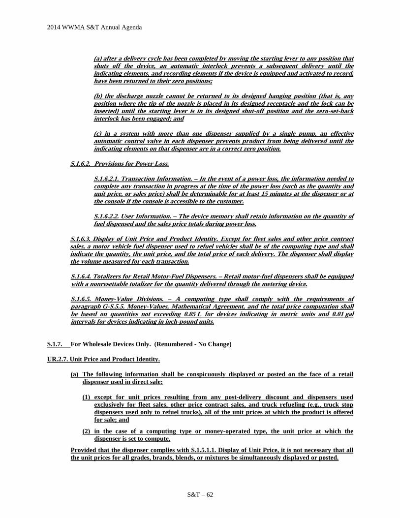
2014 WWMA S&T Annual Agenda
S&T – 62
(a) after a delivery cycle has been completed by moving the starting lever to any position that shuts off the device, an automatic interlock prevents a subsequent delivery until the indicating elements, and recording elements if the device is equipped and activated to record, have been returned to their zero positions; (b) the discharge nozzle cannot be returned to its designed hanging position (that is, any position where the tip of the nozzle is placed in its designed receptacle and the lock can be inserted) until the starting lever is in its designed shut-off position and the zero-set-back interlock has been engaged; and (c) in a system with more than one dispenser supplied by a single pump, an effective automatic control valve in each dispenser prevents product from being delivered until the indicating elements on that dispenser are in a correct zero position.
S.1.6.2. Provisions for Power Loss.
S.1.6.2.1. Transaction Information. – In the event of a power loss, the information needed to complete any transaction in progress at the time of the power loss (such as the quantity and unit price, or sales price) shall be determinable for at least 15 minutes at the dispenser or at the console if the console is accessible to the customer.
S.1.6.2.2. User Information. – The device memory shall retain information on the quantity of fuel dispensed and the sales price totals during power loss.
S.1.6.3. Display of Unit Price and Product Identity. Except for fleet sales and other price contract sales, a motor vehicle fuel dispenser used to refuel vehicles shall be of the computing type and shall indicate the quantity, the unit price, and the total price of each delivery. The dispenser shall display the volume measured for each transaction. S.1.6.4. Totalizers for Retail Motor-Fuel Dispensers. – Retail motor-fuel dispensers shall be equipped with a nonresettable totalizer for the quantity delivered through the metering device. S.1.6.5. Money-Value Divisions. – A computing type shall comply with the requirements of paragraph G-S.5.5. Money-Values, Mathematical Agreement, and the total price computation shall be based on quantities not exceeding 0.05 L for devices indicating in metric units and 0.01 gal intervals for devices indicating in inch-pound units.
S.1.7. For Wholesale Devices Only. (Renumbered - No Change) UR.2.7. Unit Price and Product Identity.
(a) The following information shall be conspicuously displayed or posted on the face of a retail dispenser used in direct sale:
(1) except for unit prices resulting from any post-delivery discount and dispensers used exclusively for fleet sales, other price contract sales, and truck refueling (e.g., truck stop dispensers used only to refuel trucks), all of the unit prices at which the product is offered for sale; and
(2) in the case of a computing type or money-operated type, the unit price at which the dispenser is set to compute.
Provided that the dispenser complies with S.1.5.1.1. Display of Unit Price, it is not necessary that all the unit prices for all grades, brands, blends, or mixtures be simultaneously displayed or posted.

2014 WWMA S&T Annual Agenda
S&T –63
(b) The following information shall be conspicuously displayed or posted on each side of a retail dispenser used in direct sale:
(1) the identity of the product in descriptive commercial terms; and
(2) the identity of the grade, brand, blend, or mixture that a multi-product dispenser is set to deliver.
UR.2.8 Computing Device. – Any computing device used in an application where a product or grade is offered for sale at one or more unit prices shall be used only for sales for which the device computes and displays the sales price for the selected transaction. The following exceptions apply:
(a) Fleet sales and other price contract sales are exempt from this requirement. (b) A truck stop dispenser used exclusively for refueling trucks is exempt from this requirement
provided that:
(1) all purchases of fuel are accompanied by a printed receipt of the transaction containing the applicable price per gallon, the total gallons delivered, and the total price of the sale; and (Added 1993)
(2) unless a dispenser complies with S.1.6.4.1. Display of Unit Price, the price posted on the
dispenser and the price at which the dispenser is set to compute shall be the highest price for any transaction which may be conducted. (Added 1993)
(c) A dispenser used in an application where a price per unit discount is offered following the delivery is exempt from this requirement, provided the following conditions are satisfied:
(1) the unit price posted on the dispenser and the unit price at which the dispenser is set to
compute shall be the highest unit price for any transaction;
(2) all purchases of fuel are accompanied by a printed receipt recorded by the system for the transaction containing:
a. the product identity by name, symbol, abbreviation, or code number;
b. transaction information as shown on the dispenser at the end of the delivery and prior to
any post-delivery discount including the:
1. total volume of the delivery;
2. unit price; and
3. total computed price of the fuel sale prior to post-delivery discounts being applied.
c. an itemization of the post-delivery discounts to the unit price; and
d. the final total price of the fuel sale.
For systems equipped with the capability to issue an electronic receipt, the customer may be given the option to receive the receipt electronically (e.g., via cell phone, computer, etc.)
Background / Discussion:

2014 WWMA S&T Annual Agenda
S&T – 64
NCWM Publication 14 checklist for Liquefied Natural Gas (LPG) Retail Motor Fuel Devices verifies compliance with specifications, such as: “Power Loss” (which requires a 15 minute power back up) and “Zero-Setback Interlocks.” However, these specifications are not located in Section 3.32 of NIST Handbook 44. There are LPG devices with NTEP Certificates of Conformance that meet current “power loss” and “zero-setback interlock” requirements. However, there are other LPG retail motor-fuel devices in the field that consist of an assembly of separable, compatible, and type-certified LPG measuring and indicating elements, key/card lock systems that do not meet the power loss and interlock requirements because those requirements are not within the LPG Code and have not been submitted for type evaluation. This creates unfair competition with holders of type certifications for LPG retail dispensers. There are newer LPG dispensers coming in to use, where measuring, indicating, and computing elements are assembled in Gilbarco retail motor fuel dispenser housings. These LPG devices serve as both propane bottle fillers and as retail motor fuel devices using separate hoses and nozzles on a dispenser. Many of these dispensers, while they do have a good safety history, are not assembled in compliance with safety standards such as UL 495 or 1238, or NFPA 50. Nor are they typically installed in accordance with NFPA 30A or NFPA 70. Existing retail LPG dispensers can be adapted to fuel LPG-powered motor vehicles by adding a simple adaptor which attaches to the LPG nozzle on the dispensers hose. There are currently 5 active and 2 inactive NTEP Certificates of Conformance for LPG retail motor-fuel dispensers listed in the NCWM Database. At the 2014 NCWM Interim Meeting Ms. Juana Williams (NIST OWM) commented that OWM believes these changes will better align the LMD and LPG Code with regard to retail dispensing systems. OWM suggests that the following specific items be considered as the item is further developed: Nonretroactive Status: OWM notes that some of the paragraphs in the original proposal are suggested as nonretroactive requirements. In reviewing these paragraphs, consideration should be given as to the appropriate nonretroactive date to propose and whether or not the effective dates provided should mirror the effective dates of corresponding paragraphs in the LMD Code. S.1.4.3. Provisions for Power Loss: OWM questions whether or not the provisions for power loss in the proposed paragraph “S.1.4.3.1. Transaction Information” should be restricted to “computing” retail LPG dispensers. This corresponding requirement applies to all retail devices in the LMD Code, not just computing-type devices. If a power loss occurs during the use of a digital volume-only retail LPG dispenser, it would seem appropriate to require provisions to ensure that the quantity information can be recalled so that the transaction can be completed. It isn’t clear why there would need to be a distinction between vehicle-mounted and stationary applications. Additionally, the language proposed in S.1.4.3.1. Transaction Information has some language that doesn’t read correctly. OWM offers the following alternative:
S.1.4.3. Provisions for Power Loss. S. 1.4.3.1. Transaction Information.
In the event of a power loss, the information needed to complete any transaction in progress at the time of the power loss (such as the quantity and unit price, or sales price) shall be determinable for at least 15 minutes at the dispenser or at the console if the console is accessible to the customer.
S 1.4.3.2. User Information. – The device memory shall retain information on the quantity of fuel dispensed and the sales price totals during power loss.
S.1.5.1.1. Unit Price: Consideration should be given to whether or not provision needs to be made for “blends” of

2014 WWMA S&T Annual Agenda
S&T –65
product for this application. Additionally, the references to paragraph S.1.6.8. refers to an LMD Code paragraph; this reference should be deleted and, perhaps, replaced with a corresponding paragraph of the LPG Code. Post-Delivery Discounts: For consistency with the LMD Code, the Committee may wish to consider whether provisions for post-delivery discounts should be added to the LPG Code. S.1.4.1. Indication of Delivery: OWM suggests that the Committee consider modifying paragraph S.1.4.1. Indication of Delivery as follows so that it mirrors the corresponding paragraph (S.1.6.1. Indication of Delivery) in the LMD Code, both in language and in the requirement for electronic devices to inhibit indications until fueling conditions ensure that the delivery starts on zero.
S.1.4.1. Indication of Delivery. – A retail device shall be constructed to show automatically show on its face the initial zero condition and the amounts quantity delivered up to the nominal capacity of the device. However, the following requirements shall apply:
For electronic devices manufactured prior to January 1, 2006, the first 0.03 L (or 0.009 gal) of a delivery and its associated total sales price need not be indicated.
For electronic devices manufactured on or after January 1, 2006, the measurement, indication of delivered quantity, and the indication of total sales price shall be inhibited until the fueling position reaches conditions necessary to ensure that the delivery starts at zero.
[Nonretroactive as of January 1, 2006]
(Amended 2014)
OWM suggests the Committee consider what nonretroactive dates, if any, should be associated with this paragraph. S.1.6.2. Provisions for Power Loss: It would seem that the provisions for power loss are already addressed in the proposed paragraph S.1.4.3. Power Loss. Therefore, OWM would suggest deleting S.1.6.2. and its subparagraphs S.1.6.2.1. and S.1.6.2.2. S.1.6.3. Display of Unit Price: This proposed paragraph is logical. However, OWM questions whether the last sentence regarding volume display is needed given that the “quantity” is already required in the previous sentence. UR.2.7. (a) (2) Unit Price and Product Identity Wholesale: The word “device” is missing after the word “type.” UR.2.8. Computing Device: Delete “Added” dates from parts (b)(1) and (b)(2). This paragraph may also be impacted by action on 310-2 and 330-1, which address requirements for recorded representations in the General and LMD Codes. Should the proposal in 310-2 to reference the use of electronic receipts be adopted, the corresponding reference in this proposed paragraph (UR.2.8.) should be deleted. Agreement Between Indications on Auxiliary Elements: Consideration should be given to including a paragraph corresponding to LMD Code paragraph S.1.6.6. which addresses agreement of indications with auxiliary elements such as consoles. General: As part of this overall proposal, consideration should be given to modifying other sections of the LPG Code to mirror the LMD Code more exactly. This could be done by the Technical Advisor and presented to the submitter as the item is further developed if that would be helpful. The Committee heard comments from John Young (Yolo County California) in support of the proposed changes. The Committee heard comments from OWM (see above) and Mr. Rich Miller (FMC) regarding the need to more closely examine the power loss requirements and how these apply to specific categories of LPG metering systems. Mr. Miller noted concern in particular that separate batteries have been required for some vehicle-mounted applications in Europe and this has proven problematic for companies.

2014 WWMA S&T Annual Agenda
S&T – 66
The Committee supports the objective of making changes to align the LPG and the LMD Code with respect to requirements for retail motor-fuel dispensing applications. Based on the comments received, the Committee believes that additional work is needed before considering the proposal for voting and decided to designate the item as a “Developing” Item to allow the submitter to address the points raised. At the 2014 NCWM Annual Meeting there were numerous comments indicating that additional work is needed on this item. The Committee agreed to recommend this item remain a “Developing” Item. Regional Associations Comments: The WWMA believes the proposal has merit and contains a complete proposal addressing the issues. The WWMA believes more time is needed for input from other stakeholders and regional associations. The WWMA forwarded this item to NCWM and recommended that it be an Informational Item. SWMA did not receive any comments opposing the item if the section is the same as the LMD Code. The SWMA recommended the item be moved forward to the NCWM as a Voting Item. CWMA supported this item as a Developing item.
Item 332-1
Summary of comments considered by the regional committee (in writing or during the open hearings): Steve Cook, CA, spoke that the revised proposal reflects changes made due to comments by NIST OWM. Gordon Johnson, Gilbarco, questioned whether or not there should be a General Code to address common factors in all LMD requirements. Paul Jordan, Ventura County, feels this item will have a large impact on existing device owners. Kurt Floren, Los Angeles County, questioned the language in S.1.5.4 “quantity value can be different as long as they agree”. Scott Simmons, CO, cautioned to carefully consider this proposal as he is not sure this is a problem and may be costly to the industry. The following amended language was provided by the submitter. Item as proposed by the regional committee: (If different than agenda item)
S.1.3. Indicators.
S.1.3.6. Transaction Information. In the event of a power loss, the information needed to complete any transaction in progress at the time of the power loss (such as the quantity and unit price, or sales price) shall be determinable for at least 15 minutes at the device or other onsite device accessible to the customer.
[Nonretroactive as of January 1, 201X]
(Added 201X)
S.1.4. For Retail Devices Only.
S.1.4.3. Zero-Set-Back Interlock for Retail Motor-Fuel Devices – A retail motor-fuel device shall be constructed so that:
(a) after a delivery cycle has been completed by moving the starting lever to any position that shuts off the device, an automatic interlock prevents a subsequent delivery until the indicating elements, and recording elements if the device is equipped and activated to record, have been returned to their zero positions; (b) the discharge nozzle cannot be returned to its designed hanging position (that is, any position where the tip of the nozzle is placed in its designed receptacle and the lock can be inserted) until the starting lever is in its designed shut-off position and the zero-set-back interlock has been engaged; and

2014 WWMA S&T Annual Agenda
S&T –67
(c) in a system with more than one dispenser supplied by a single pump, an effective automatic control valve in each dispenser prevents product from being delivered until the indicating elements on that dispenser are in a correct zero position.
[Nonretroactive as of January 1, 201X]
(Added 201X)
S.1.5. For Stationary Retail Devices Only.
S.1.5.1. Display of Unit Price and Product Identity. – In a device of the computing type, means shall be provided for displaying on each face of the device the unit price at which the device is set to compute or to deliver as the case may be, and there shall be conspicuously displayed on each side of the device the identity of the product that is being dispensed. If a device is so designed as to dispense more than one grade, brand, blend, or mixture of product, the identity of the grade, brand, blend, or mixture being dispensed shall also be displayed on each face of the device.
(a) A computing or money-operated device shall be able to display on each face the unit price at which the device is set to compute or to dispense. (b) Except for dispensers used exclusively for fleet sales, other price contract sales, all of the unit prices at which that product is offered for sale shall meet the following conditions:
(1) For a system that applies a discount prior to the delivery, all unit prices shall be displayed or shall be capable of being displayed on the dispenser through a deliberate action of the purchaser prior to the delivery of the product. It is not necessary that all of the unit prices be simultaneously displayed prior to the delivery of the product.
(2) For a system that offers post-delivery discounts on fuel sales, display of predelivery unit price information is exempt from (b)(1), provided the system complies with S.1.5.7. Recorded Representations for Transactions Where a Post-Delivery Discount(s) is Provided.
Note: When a product is offered at more than one unit price, display of the unit price information may be through the deliberate action of the purchaser: 1) using controls on the device; 2) through the purchaser’s use of personal or vehicle-mounted electronic equipment communicating with the system; or 3) verbal instructions by the customer.
[Nonretroactive as of January 1, 201X]
(Added 201X)
S.1.5.4. Agreement Between Indications.
(a) When a quantity value indicated or recorded by an auxiliary element is a derived or computed value based on data received from a device, the value may differ from the quantity value displayed on the dispenser, provided that the following conditions are met:
(1) all total values for an individual sale that are indicated or recorded by the system agree, and
(2) Within each element, the values indicated or recorded meet the formula (quantity x unit price = total sales price) to the closest cent.
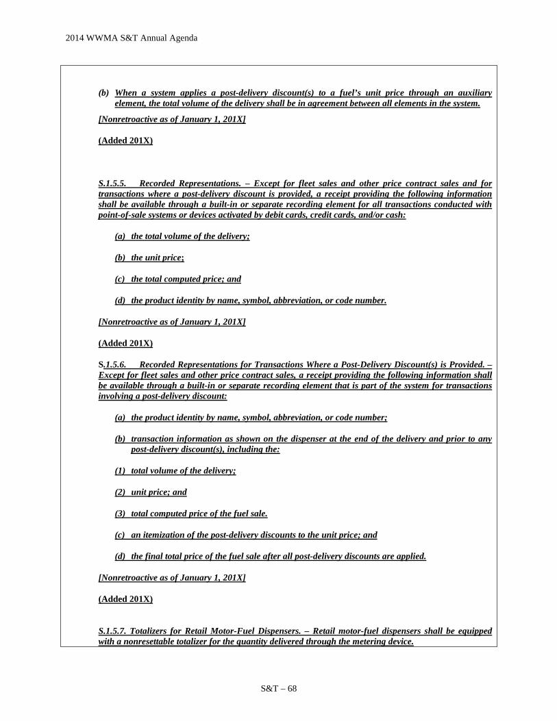
2014 WWMA S&T Annual Agenda
S&T – 68
(b) When a system applies a post-delivery discount(s) to a fuel’s unit price through an auxiliary element, the total volume of the delivery shall be in agreement between all elements in the system.
[Nonretroactive as of January 1, 201X]
(Added 201X)
S.1.5.5. Recorded Representations. – Except for fleet sales and other price contract sales and for transactions where a post-delivery discount is provided, a receipt providing the following information shall be available through a built-in or separate recording element for all transactions conducted with point-of-sale systems or devices activated by debit cards, credit cards, and/or cash:
(a) the total volume of the delivery;
(b) the unit price;
(c) the total computed price; and
(d) the product identity by name, symbol, abbreviation, or code number.
[Nonretroactive as of January 1, 201X]
(Added 201X)
S.1.5.6. Recorded Representations for Transactions Where a Post-Delivery Discount(s) is Provided. – Except for fleet sales and other price contract sales, a receipt providing the following information shall be available through a built-in or separate recording element that is part of the system for transactions involving a post-delivery discount:
(a) the product identity by name, symbol, abbreviation, or code number;
(b) transaction information as shown on the dispenser at the end of the delivery and prior to any post-delivery discount(s), including the:
(1) total volume of the delivery;
(2) unit price; and
(3) total computed price of the fuel sale.
(c) an itemization of the post-delivery discounts to the unit price; and
(d) the final total price of the fuel sale after all post-delivery discounts are applied.
[Nonretroactive as of January 1, 201X]
(Added 201X)
S.1.5.7. Totalizers for Retail Motor-Fuel Dispensers. – Retail motor-fuel dispensers shall be equipped with a nonresettable totalizer for the quantity delivered through the metering device.

2014 WWMA S&T Annual Agenda
S&T –69
[Nonretroactive as of January 1, 201X]
(Added 201X)
UR.2. Use Requirements.
UR.2.7. For Stationary Retail Computing Type Devices Only Installed After January 1, 201X.
UR.2.7.1. Unit Price and Product Identity.
(a) The following information shall be conspicuously displayed or posted on the face of a retail dispenser used in direct sale:
(1) except for unit prices resulting from any post-delivery discount and dispensers used
exclusively for fleet sales, other price contract sales, and truck refueling (e.g., truck stop dispensers used only to refuel trucks), all of the unit prices at which the product is offered for sale; and
(2) in the case of a computing type device or money-operated type device, the unit price at which the dispenser is set to compute.
Provided that the dispenser complies with S.1.5.1. Display of Unit Price and Product Identity, it is not necessary that all the unit prices be simultaneously displayed or posted.
(b) The following information shall be conspicuously displayed or posted on each side of a retail dispenser used in direct sale:
(1) the identity of the product in descriptive commercial terms; and (2) the identity of the grade, brand, blend, or mixture that a multi-product dispenser is set
to deliver.
(Added 201X)
UR.2.7.2. Computing Device. – Any computing device used in an application where a product or grade is offered for sale at one or more unit prices shall be used only for sales for which the device computes and displays the sales price for the selected transaction. The following exceptions apply:
(a) Fleet sales and other price contract sales are exempt from this requirement. (b) A truck stop dispenser used exclusively for refueling trucks is exempt from this requirement
provided that: (1) all purchases of fuel are accompanied by a printed receipt of the transaction containing
the applicable price per unit of measure, the total quantity delivered, and the total price of the sale; and
(2) unless a dispenser complies with S.1.6.4.1. Display of Unit Price, the price posted on the dispenser and the price at which the dispenser is set to compute shall be the highest price for any transaction which may be conducted.
(c) A dispenser used in an application where a price per unit discount is offered following the delivery is exempt from this requirement, provided the following conditions are satisfied: (1) the unit price posted on the dispenser and the unit price at which the dispenser is set to
compute shall be the highest unit price for any transaction; (2) all purchases of fuel are accompanied by a receipt recorded by the system for the
transaction containing: a. the product identity by name, symbol, abbreviation, or code number;

2014 WWMA S&T Annual Agenda
S&T – 70
b. transaction information as shown on the dispenser at the end of the delivery and prior to any post-delivery discount including the:
1. total volume of the delivery; 2. unit price; and 3. total computed price of the fuel sale prior to post-delivery discounts being applied.
c. an itemization of the post-delivery discounts to the unit price; and d) the final total price of the fuel sale after all post-delivery discounts are applied.
(Added 201X)
Committee recommendation to the region:
Voting Item on the NCWM Agenda Information Item on the NCWM Agenda Withdraw the Item from the NCWM Agenda (In the case of new items, do not forward to NCWM) Developing Item on the NCWM Agenda (To be developed by source)
Reasons for the committee recommendation: The WWMA S&T Committee addressed comments received during open hearings. The Committee recommended the item be informational to allow for additional review, comment and future consideration, including whether or not the retroactive dates should mirror the effective dates of similar paragraphs in the LMD codes.
COMPLETE SECTION BELOW FOLLOWING VOTING SESSION
Final updated or revised proposal from the region: (If different than regional committee recommendation) Regional recommendation to NCWM for item status:
Voting Item on the NCWM Agenda Information Item on the NCWM Agenda Withdraw the Item from the NCWM Agenda (In the case of new items, do not forward to NCWM) Developing Item on the NCWM Agenda (To be developed by source) Unable to consider at this time (Provide explanation in the “Additional Comments” section below)
Regional Report to NCWM: Please provide your report in this section exactly how you want it to appear in the NCWM reports to represent your region’s considerations, support or opposition, and recommendations. This will replace any previous reports from your region on this item. The submitter of the item provided and update during the 2014 WWMA Annual Meeting open hearing and stated that several changes have been made to address NIST OWM concerns. Several regulators spoke that this may impact owners of devices that are currently in use and urged caution. The submitter provided several updates to the WWMA S&T Committee to address comments heard during open hearing. These changes were included on the addendum sheet prior to the voting session. The WWMA agreed to include this as an Information Item on the NCWM agenda to allow for additional review, comment and future consideration; including whether or not the retroactive dates should mirror the effective dates of similar paragraph in the LMD code. Additional letters, presentations, and data may have been part of the Committee’s consideration. Please refer to http://ncwm.net/meetings/annual/publication-16 to review these documents.
2014 WWMA S&T Annual Agenda
S&T –71
332-2 N.3. Test Drafts (NEW)
Source: Endress + Hauser Flowtec AG USA Purpose: Allow transfer standard meters to be used to test and place into service dispensers and delivery system flow meters.
Item Under Consideration: Amend NIST Handbook 44 LPG and Anhydrous Ammonia Liquid-Measuring Devices as follows:
N.3. Test Drafts. – N.3.1 Minimum Test - Test drafts should be equal to at least the amount delivered by the device in one minute at its normal discharge rate. (Amended 1982) N.3.2. Transfer Standard Test. – When comparing a meter with a calibrated transfer standard, the test draft shall be equal to at least the amount delivered by the device in 2 minutes at its maximum discharge rate.
Background / Discussion: The use of transfer standards is recognized in Code sections 3.34 Cryogenic Liquid-Measuring Devices Code and 3.38 Carbon Dioxide Liquid-Measuring Devices Code and 3.39 Hydrogen Gas-Measuring Devices – Tentative Code. Field evaluation of LPG meters and CNG dispensers and LNG dispensers is very difficult using volumetric and gravimetric field standards and methods. The tolerances for these applications are such that using transfer meter standards are more efficient and safer. With CNG and LNG and LPG applications, the transfer standard meters are placed in-line with the delivery system as it is used to fill tanks and vehicles. The use of transfer standards eliminates return to storage issues. The use of transfer standard meters is easier and faster compared to the use of traditional field standards. The cost of using transfer standards and transporting them is much less than the cost of traditional field provers and standards. Recognition in Handbook 44 will enable States to allow transfer standard meters to place systems into service and for field enforcement. Volumetric field provers and gravimetric field proving are susceptible to environmental influences. The State of Colorado uses a master meter to test propane delivery truck meters. The State of Nebraska has used a mass flow meter to test agricultural chemical meters. In some applications, transfer standard meters are not more accurate than the meters used in the dispenser. For that reason, longer test drafts and possibly more tests need to be run. The State of California is purported to have conducted a short study of master meters in the past. The conclusion did not lead to wide adoption of the practice. However, the State of California uses a mass flow meter as a master meter for carbon dioxide flowmeter enforcement. Mass Flow Meters user requirement U.R.3.8. Return of Product to Storage, Retail Compressed Natural Gas Dispensers requires that the natural gas which is delivered into the test container must be returned to storage. This is difficult and most often not complied with when the test vessel contents are released to atmosphere. The S&T Committee might also consider amending Sections 3.30 Liquid-Measuring Devices Code and 3.31 Vehicle-Tank Meters Code to allow transfer standard meters.
Item 332-2
Summary of comments considered by the regional committee (in writing or during the open hearings): Gordon Johnson, Gilbarco, stated that the need for a master meter test is present and would solve several issues in

2014 WWMA S&T Annual Agenda
S&T – 72
regard to these types of tests. Carol Hockert, NIST OWM, stated that uncertainties of this type of measurement need to be fully evaluated prior to adopting any test methods. Item as proposed by the regional committee: (If different than agenda item) Committee recommendation to the region:
Voting Item on the NCWM Agenda Information Item on the NCWM Agenda Withdraw the Item from the NCWM Agenda (In the case of new items, do not forward to NCWM) Developing Item on the NCWM Agenda (To be developed by source)
Reasons for the committee recommendation: The WWMA S&T Committee feels that additional information and establishment of test procedures and data is needed to further evaluate the proposal.
COMPLETE SECTION BELOW FOLLOWING VOTING SESSION
Final updated or revised proposal from the region: (If different than regional committee recommendation) Regional recommendation to NCWM for item status:
Voting Item on the NCWM Agenda Information Item on the NCWM Agenda Withdraw the Item from the NCWM Agenda (In the case of new items, do not forward to NCWM) Developing Item on the NCWM Agenda (To be developed by source) Unable to consider at this time (Provide explanation in the “Additional Comments” section below)
Regional Report to NCWM: Please provide your report in this section exactly how you want it to appear in the NCWM reports to represent your region’s considerations, support or opposition, and recommendations. This will replace any previous reports from your region on this item. At the 2014 WWMA Annual Meeting testimony was presented that this type of technology would more easily facilitate inspections. However, it was also stated that a more comprehensive evaluation of the equipment and testing procedure, including the associated uncertainty, be performed. The WWMA agreed that this type of technology would be useful but it should be a Developing Item to allow the submitter to provide a more complete analysis.
337 MASS FLOW METERS
337-1 Appendix D – Definitions: Diesel Liter Equivalent (DLE) and Diesel Gallon Equivalents (DGE) for Compressed Natural Gas and Liquefied Natural Gas; Definition of Gasoline Gallon Equivalent and Gasoline Liter Equivalent for Compressed Natural Gas; S.1.2. Compressed Natural Gas and Liquefied Natural Gas Dispensers; S.1.3.1.1. Compressed Natural Gas Used as an Engine Fuel; S.1.3.1.2. Liquefied Natural Gas Used as an Engine Fuel; S.5.2. Marking of Diesel and Gasoline Volume Equivalent Conversion Factor; Compressed Natural Gas, S.5.3. Marking of Diesel Volume Equivalent Conversion Factor; Liquefied Natural Gas, UR.3.1.1. Marking of Equivalent Conversion Factor for Compressed Natural Gas, UR.3.1.2. Marking of Equivalent Conversion Factor for Liquefied Natural Gas, and UR.3.8. Return of Product to Storage, Retail Compressed Natural Gas and Liquefied Natural Gas

2014 WWMA S&T Annual Agenda
S&T –73
Source: Clean Vehicle Education Foundation (2014) Purpose: Since natural gas is sold in the retail market place as compressed natural gas (CNG) and liquefied natural gas (LNG) an alternative fuel to gasoline and diesel fuel, the proposed additions and edits to Handbook 44 will provide definitions for volume units of CNG and LNG that are the energy equivalents for diesel liters and gallons so that end users can readily compare cost and fuel economy. At present only equivalents for gasoline are included in NIST Handbooks 44 and 130 for CNG as an engine fuel. The proposal also includes modification to definitions for gasoline volume equivalents to clarify those terms apply to CNG. Item Under Consideration: Amend NIST Handbook 44 Appendix D to include new definitions as follows:
diesel gallon equivalent (DGE). – means 6.384 pounds of compressed natural gas or 6.059 pounds of liquefied natural gas. [3.37] (Added 2014) diesel liter equivalent (DLE). – means 0.765 kilograms of compressed natural gas or 0.726 kilograms of liquefied natural gas. [3.37] (Added 2014)
Amend NIST Handbook 44 Appendix D definitions as follows:
gasoline gallon equivalent (GGE). – Gasoline gallon equivalent (GGE) means 5.660 pounds of compressed natural gas.[3.37] (Added 1994)(Amended 2014) gasoline liter equivalent (GLE). – Gasoline liter equivalent (GLE) means 0.678 kilograms of compressed natural gas.[3.37] (Added 1994)(Amended 2014)
Amend NIST Handbook 44 Mass Flow Meters Code paragraphs S.1.2., S.1.3.1.1., S.5.2., and UR.3.8. and add new paragraphs S.1.3.1.2., S.5.3., UR.3.1.1. and UR.3.1.2. as follows:
S.1.2. Compressed Natural Gas and Liquefied Natural Gas Dispensers. – Except for non-retail fleet sales and other price contract sales, a compressed natural gas and liquefied natural gas dispensers used to refuel vehicles shall be of the computing type and shall indicate the quantity, the unit price, and the total price of each delivery. The dispensers shall display the mass measured for each transaction either continuously on an external or internal display accessible during the inspection and test of the dispensers, or display the quantity in mass units by using controls on the device. (Added 1994)(Amended 2014)
S.1.3. Units
S.1.3.1.1. Compressed Natural Gas Used as an Engine Fuel. – When compressed natural gas is dispensed as an engine fuel, the delivered quantity shall be measured in mass and indicated in “gasoline liter equivalent (GLE) units,” “gasoline gallon equivalent (GGE) units,” diesel liter equivalent (DLE) units, or diesel gallon equivalent (DGE) units (Also see definitions). (Added 1994)(Amended 2014)

2014 WWMA S&T Annual Agenda
S&T – 74
S.1.3.1.2. Liquefied Natural Gas Used as an Engine Fuel. – When liquefied natural gas is dispensed as an engine fuel, the delivered quantity shall be measured in mass and indicated in “diesel liter equivalent (DLE) units” or “diesel gallon equivalent (DGE) units” (Also see definitions). (Added 2014)
UR.3.8. Return of Product to Storage, Retail Compressed Natural Gas and Liquefied Natural Gas Dispensers. – Provisions at the site shall be made for returning product to storage or disposing of the product in a safe and timely manner during or following testing operations. Such provisions may include return lines, or cylinders adequate in size and number to permit this procedure. (Added 1998)(Amended 2014) Background / Discussion: This item was presented as a voting item at the 2014 NCWM Annual Meeting, but was returned to committee because it failed in one of the two houses. The gasoline gallon equivalent (GGE) unit was defined by NCWM in 1994 to allow users of natural gas vehicles to readily compare costs and fuel economy of light-duty compressed natural gas vehicles with equivalent gasoline powered vehicles. More background on the efforts of NIST/NCWM is available in the Reports of the 78th and 79th NCWM in NIST Special Publication 854 and 870 (see pages 322 and 327, respectively). Natural gas is sold as a vehicle fuel as either Compressed Natural Gas (CNG) or Liqufied Natural Gas (LNG). For medium and heavy duty natural gas vehicles in widespread use today, there is a need to officially define a unit allowing a comparison of cost and fuel economy with diesel powered vehicles. The submitter stated that the official definition of a DLE and a DGE will likely provide justification for California, Wisconsin and many other states to permit retail sales of CNG for heavy-duty vehicles in these convenient units. The submitter has provided a mathematicaljustification for the specific quantity (mass) of compressed natural gas in a DLE and DGE which is included in Appendix D. January 2013 NCWM Interim Meeting At the 2013 NCWM Interim Meeting, the Committee heard multiple comments in opposition to the proposal. Mr. Michael Keilty (Endress + Hauser Flowtec AG, USA) opposed the proposal, noting that a truck running on LNG would be dedicated to that type of fuel; thus, there is no need to make comparisons with diesel fuel on an ongoing basis. He stated that he believes natural gas should be sold in units of mass.
Ms. Williams reviewed the following points prepared by OWM and suggested that the Committee consider these points in its deliberations on the proposals for this Item and Item 337-2 (a proposal to recognize a gasoline and diesel volume equivalent unit for CNG, a diesel volume equivalent for LNG engine fuel and for marking the fuel dispenser). A copy of these points was also provided to the S&T Committee and the L&R Committee in writing in advance of the Interim Meeting.
Collaborative Work Effort Work in joint session with the NCWM L&R Committee on corresponding L&R Agenda Items 232-1 (a proposal to recognize the diesel volume equivalent MOS for vehicle fuel) and 237-1 (a proposal to define the diesel volume equivalent unit in relation to mass) which specify the allowable unit of measurement for advertising and sale of natural gas. This collaboration between committees will ensure that the proposed volume equivalent unit for a delivery is properly indicated and calculated by a natural gas dispenser. Facilitate Marketplace-Value Comparisons A dispenser might serve vehicles that are powered by diesel or gasoline fuel. Therefore, which volume equivalent unit (the DGE or GGE) is appropriate to avoid confusing the consumer? What is the most appropriate means to provide sufficient information to customers attempting to make a comparison of fuel offered by the DGE and GGE, whether at the same station or stations on adjacent street corners? Today’s value comparisons are made to petroleum products, but as other alternative fuels proliferate how easy will it be for consumers to make comparisons to other fuels such as electricity or hydrogen?

2014 WWMA S&T Annual Agenda
S&T –75
An alternative that would provide more flexibility for comparison with other fuels and which would potentially create less confusion than permitting multiple different “equivalent” values as “units” of measure is to require the sale of all natural gas in mass units (kg or lb) as suggested by the SWMA. With this approach, customers could still be provided with supplemental information through mechanisms such as pump toppers that provide information about estimated equivalent units of measurement for deliveries indicated in mass as well as information on web sites such as those that already provide information about fuel economy. This approach might also reduce complaints from some suppliers about the accuracy of equivalent values relative to their product. Another point that has been raised by some in the community and should be considered by the Committee is whether or not “equivalent values” are as necessary as they might have been at one time to encourage consumer acceptance of natural gas as an alternative fuel. For example, the SWMA questioned whether, once a consumer has purchased a vehicle he or she has the need to make ongoing value comparisons or whether this information is more useful prior to purchasing a vehicle. Given the concerns about consumer confusion with a potential proliferation of “equivalent” values at the dispenser, perhaps requiring mass units on the dispenser (with supplemental information about equivalents) is a more appropriate approach. Compliance of Existing Approved Equipment-Indications As noted above, NIST OWM suggests the Committee consider SWMA’s recommendation for equipment to indicate in a mass unit of measurement. Currently, there are two LNG dispensers with NCWM NTEP Certificates of Conformance (CC). They are NCWM CC 02-075A2* (Chart Industries) and NCWM CC 04-073A1 (NorthStar, Inc.), which specify these dispensers display in mass. How will the proposal apply to this equipment which may not have the capability to display in units other than mass? Earlier S&T Committee Positions Does the S&T Committee plan to revisit its 1999 recommendation where it requested data on LNG be submitted prior to the recognition of this product in a metering application? The Committee might also recall that the S&T Committee took a position in 2008 on a related proposal to recognize the “DGE” recommending that a consensus between stakeholders exist on any single energy value used as a conversion factor. NIST OWM notes that several CNG suppliers have raised concerns about the use of 5.660 lb of CNG for each GGE commenting that this value is too low for the fuel they are providing to customers. OWM asks are other sectors, which rely on the accurate accounting of vehicle motor fuel sales, aware of and in agreement with the proposed mass to volume equivalent unit being proposed as a conversion factor value for natural gas (CNG and LNG)? The data for the heating values cited in Table B.4. “Heat Content for Various Fuels” in the Transportation Energy Data Book Edition 30 (June 2011) and used to justify the factors for the conversion of mass to “equivalent volume units” was not developed as part of an NCWM study, but represents an account of work by a government sponsored agency to characterize transportation activity and other factors that influence transportation energy use. The book includes a disclaimer which states “in any attempt to compile a comprehensive set of statistics on transportation activity, numerous instances of inadequacies and inaccuracies in the basic data are encountered;” points out that “an appendix is included to document the estimation procedures;” and notes that “neither ORNL nor DOE endorses the validity of these data.”
Ms. Kristin Macey (CA) opposed the proposal and urged the Committee to stop the proliferation of “equivalent units.” She noted that mass units are perfectly good for routine transactions and echoed comments that comparisons with other fuels are only relevant when making a vehicle purchase decision. Ms. Carol Hockert (NIST OWM) further suggested that, during its deliberations, the Committee should consider how the establishment of artificial units would affect metrological traceability. Mr. Dmitri Karimov (Liquid Controls Corporation, LLC), speaking on behalf of MMA, agreed with Ms. Hockert, noting that extensive work is done by companies to establish and maintain metrological traceability and the establishment of what amounts to arbitrary values is counterproductive. Mr. Dan Peterson (Yokogawa Corporation of America) echoed all of the statements made in opposition to the proposal.

2014 WWMA S&T Annual Agenda
S&T – 76
Mr. Curtis Williams (CP Williams Energy Consulting) stated that he has had concerns about the use of the GGE and GLE for some years and he is glad that some are questioning the need to reconsider the use of equivalent units. As a participant in the U.S. National Working Group on Hydrogen, he was grateful that the associated code for that alternative fuel established requirements for mass units. He suggested that the Committee also consider examining the potential use of mass units for other fuels and noted that the use of mass units also eliminates questions about temperature compensation.
Ms. Judy Cardin (WI) acknowledged the need for the L&R Committee and the S&T Committee to work together on this and related items. She cited two main tasks to be addressed as: What is the right conversion value for the proposed units and Should units for the sale of natural gas be in “equivalent” units or mass units?
The Committee heard no comments in support of the proposal during its Open Hearings.
During its work sessions at the Interim Meeting, the S&T Committee met with the L&R Committee to discuss this item and related items on the two Committees’ agendas; the corresponding items on the L&R Committee Agenda are Items 232-1 and 237-1. During the joint meeting, the L&R Committee advised the S&T Committee that it had decided to make the related item on their agenda “Informational” to allow additional time for the community to study the issue and hear from other stakeholders in the community. A proposal was made to ask the FALS to deliberate on an appropriate equivalent value for each of the proposed “units.” However, the two Committees recognized that before asking the FALS to expend resources on further definitions, the questions and concerns raised in the Open Hearings regarding the appropriateness of recognizing such units should first be addressed. The Committees agreed to recommend to the NCWM Chairman that a small task group be established to further study this issue. The Committees each agreed to develop a list of tasks that they would ask such a task group to take on and to recommend possible members of the group to ensure balanced representation of stakeholders. After discussion with the L&R Committee, the S&T Committee reviewed and summarized key comments made during the Open Hearings for S&T Committee Agenda items 337-1 and 337-2:
• Are equivalent units necessary to promote consumer acceptance of this fuel?
• Is there a significant need for continued comparison to other fuels once you have purchased a vehicle? Does this justify the proliferation of “equivalent” values?
• The intent is to add this for medium- and heavy-duty vehicles such as trucks that operate on LNG. Trucks that operate on LNG are generally dedicated fuel vehicles that run only on a single fuel.
• Is the dispenser the appropriate place to make comparisons with other fuels or is a better place to make those comparisons via mechanisms such as pump toppers, websites, etc.?
• Striking the word “compressed” (in the changes proposed in Item 337-2) expands the proposal to LNG.
• California’s approval of LNG meters indicating in mass units was correct.
• What will the impact be on existing approval of LNG dispensers currently indicating in mass?
• There is much opposition to the proliferation of “equivalent units” for various types of fuels.
• The current recognition of GGE and GLE units has led to complaints about equivalent values from both industry and regulatory officials.
• Mass units should be considered for natural gas and other fuels.
• Will the establishment of equivalent values provide traceability to SI units?

2014 WWMA S&T Annual Agenda
S&T –77
• The community expends significant resources to achieve good meter performance and establishing “fuzzy” equivalent values seems to undermine these efforts.
• The factor for any “equivalent unit” will represent only an “estimate” of an equivalent value.
• There is disagreement amongst the industry regarding the appropriate equivalent value in this proposal. The report containing the data that is referenced as the basis for the proposal includes a disclaimer from Oakridge National Laboratory and U.S. Department of Energy regarding its validity for other than general use in the transportation industry.
• The S&T Committee only heard comments in opposition to the proposal.
• Harmonization with OIML requirements should be considered in the method of sale and associated device requirements.
With respect to items 337-1 and 337-2, the Committee agreed to work collaboratively with the L&R Committee and to develop a small work group to decide: 1) whether or not DLE and DGE should be considered an acceptable method of sale for natural gas; and 2) if so, what should the factor be to determine their equivalents to gasoline. The Committee agreed that the above list of key points and questions heard during its Open Hearings should be considered, along with other Open Hearing comments, by the chairs of both the L&R and S&T Committee in the development of a list of points to be addressed by the Task Group. On the NCWM Online Position Forum one Government representative indicated support; one Government representative indicated a neutral position; and one Government representative indicated opposition for this item. The neutral position was accompanied by a comment suggesting the establishment of a joint Task Group and encouraging a final recommendation that would clarify whether the proposed units are or are not permitted. The opposing position was accompanied by a comment indicating opposition to artificial units of measure. Prior to the 2013 Annual Meeting, NCWM Chairman, Steve Benjamin, appointed the “NCWM Natural Gas Steering Committee,” which will be chaired by Mr. Mahesh Albuquerque (CO). The primary charge of the Committee is to educate the membership regarding: the technical issues surrounding this application; the rationale for the proposed changes; the anticipated impact of the proposed changes and issues related to their implementation. The Committee was asked to identify and address questions raised during the 2013 Interim Meeting as well as other venues in an effort to enable NCWM members to make informed decisions about proposals under consideration in this area. Also prior to the 2013 Annual Meeting, the Committee received a proposal from Mr. Douglas Horne (Clean Vehicle Education Foundation) to modify the “Item Under Consideration.” Mr. Horne proposed separate definitions for CNG and LNG gallon equivalent values. The Committee suggested he work with the steering committee to further refine the proposal and suggest changes to the item as appropriate. Mr. Horne’s proposals were posted on the NCWM website with other documents relative to the committee’s final report. While submitted in an NCWM Form 15 template, Mr. Horne’s proposal is not addressing a new issue, but rather providing comments on a current item (337-1) on the Committee’s agenda. July 2013 NCWM Annual Meeting During its 2013 Annual Meeting Open Hearings, the Committee heard an update from Steering Committee Chairman, Mr. Albuquerque. He reported that the Steering Committee met for the first time on Sunday, July 14 at the beginning of the Annual Meeting and gathered input from those in the audience. Comments indicated that consumers may find gallon equivalent information to be helpful, but the most equitable method for measuring and selling the product is based on mass measurement. At the 2013 NCWM Annual Meeting, the Committee heard comments on Items 337-1 and Items 337-2 jointly. Details of those comments are outlined below.

2014 WWMA S&T Annual Agenda
S&T – 78
The S&T Committee heard overwhelming comments opposing the use of gallon equivalents and favoring the use of mass as the method of sale. The Committee also heard multiple comments indicating concern about the establishment of a value that would be an approximation of the actual equivalent for a given transaction. Mr. Horne reported that some states have already or are in the process of enacting defined “gasoline equivalent” values; some adopted earlier versions of the equivalent and some are considering new values as outlined in Mr. Horne’s most recent proposal. Ms. Macey noted that the NCWM successfully adopted a method of sale for hydrogen fuel based on mass and suggested that the natural gas be held to the same standard. Mr. Keilty commented that sale of natural gas as a vehicle fuel has proliferated globally and those sales are based on mass units. OWM acknowledged appreciation of the establishment of the Steering Committee to further study this issue. OWM encourages the S&T Committee, the Steering Committee, and the weights and measures community to consider the points raised by OWM during the 2013 Interim Meeting as well as the following in their deliberations of Items 337-1 and Item 337-2:
In addition to discussing the proposals in Items 337-1 and 337-2, OWM requests that the Steering Committee specifically discuss and consider whether or not the continued use of the terms “GLE” and “GGE” are appropriate for commercial CNG metering applications. OWM makes this request based on many of the same points made by OWM at the 2013 Interim Meeting and also given that:
(1) this market is well established and consumer confidence and acceptance of CNG and other alternative fuels is not contingent upon continued comparisons with gasoline;
(2) there are other methods for comparing relative efficiency and costs with gasoline;
(3) experience with feedback from the community indicates problems with the application and validity of these units with changing gas supplies;
(4) the proposal in Items 337-1 and 337-2 proposes language which would address natural gas as a whole and it is, therefore, appropriate to raise the discussion of whether or not the continued use of non- traceable units is appropriate. Additionally, OWM suggests that a proposal to eliminate the use of the terms “GLE” and “GGE” in favor of indications in mass units be developed and considered by the NCWM to ensure commercial transactions for natural gas are based on NIST traceable units of measurement; and
(5) as the number of viable alternative fuel options increase, providing a relatively static comparison with only one alternative fuel will not serve the broad needs of consumers and will make it unlikely that the dispenser is the appropriate location to provide comparison information.
The Committee also heard a comment from Mr. Karimov suggesting that volume units be permitted as a method of sale for LNG. While many people expressed an understanding of the need for consumers to make comparisons with gasoline, comments indicate that such comparisons would typically be made prior to the purchase of a vehicle and possibly for a short time while becoming accustomed to the vehicle. The Committee heard comments indicating that weights and measures officials would be amenable to permitting the posting or displaying of supplemental information regarding gallon equivalent values. January 2014 NCWM Interim Meeting
The Committee met with the L&R Committee to discuss the comments received on Items 337-1 through 337-5 and corresponding items on the L&R Committee’s agenda. Although there are three new proposals on the agenda several appear to require clarification from the submitter on whether they are replacements for several carryover proposals. The two Committees heard an update from Mahesh Albuquerque (CO) speaking as Chairman of the NCWM Natural Gas Steering Committee (NGSC).

2014 WWMA S&T Annual Agenda
S&T –79
Ms. Williams reviewed the following points prepared by OWM and suggested that the Committees consider these points in their deliberations on the proposals:
• OWM encourages the: o Efforts of the NCWM Natural Gas Steering Committee as it works to provide corresponding
proposals to the L&R Committee and S&T Committee. o Collaboration with FALS on:
Fuel properties data The final vetting of data, formulas, etc. used to arrive at any conversion factors that might
be recognized for use in supplemental advertising/sales information • OWM notes that some of the current wording in the 2012 and 2013 proposals is somewhat confusing, in
part, because several paragraphs include previous conversion factors no longer under consideration. • The latest proposal encourages a proliferation of equivalent units of measurement, at least six for the CNG
and LNG RMFD applications. • Measurement accuracy and traceability are not achieved through computation of the sale’s information in
equivalent quantity units since the conversion factor is an estimated value. • OWM suggests input from stakeholders such as the CNG and LNG RMFD OEMs and agencies regulating
other sectors (such as the motor fuels taxation departments) in the natural gas infrastructure on the impact of any new proposal.
• The last point that OWM would like to suggest the Committees consider that additional work might be necessary to further modify the code to fully recognize the LNG application. NIST has plans to outline an approach for a similar project.
The S&T Committee and L&R Committee agreed with the suggestions provided by the NGSC for addressing these items. As a result of these discussions, the S&T Committee agreed to the following regarding Items 337-1 through 337-5:
• Withdraw Items 337-1 and 337-4 and consolidate the remaining three items (337-2, 337-3, and 337-5) into a single item.
• Ask that the NGSC rework its proposed changes to NIST Handbook 44 to reflect the comments heard during the Committee’s open hearings and in writing.
• Designate the consolidated item as a “Voting” item in anticipation that the NGSC will present a revised version of the proposed changes to NIST Handbook 44 prior to the publication of the Committee’s Interim Report.
If the revised version of the code is not presented prior to the publication date or agreement cannot be reached within the NGSC or the S&T Committee on the revised version, the Committee agreed to designate this consolidated item as an “Information” item. March 2014 Natural Gas Steering Committee Report to the L&R and S&T Committees The Natural Gas Steering Committee (NGSC) was formed in July 2013 to help understand and educate the NCWM membership regarding the technical issues surrounding the proposed changes to HB 44 and HB 130 submitted by the Clean Vehicle Education Foundation (CVEF), the anticipated impact of the proposed changes, and issues related to implementation requirements when compressed natural gas (CNG) and liquefied natural gas (LNG) are dispensed and sold as a retail engine fuel in gallon equivalent units. At the NCWM Interim Meeting in January 2014, Mahesh Albuquerque, chair of the NGSC provided the S&T and L&R Committees with an update from the NGSC, including proposed revisions to the proposals submitted by the CVEF. The NGSC heard comments from the floor related to the proposed revisions and requested additional time to further develop its recommendations. The S&T and L&R Committees agreed to allow the NGSC additional time to meet and develop alternative proposals to those on the S&T and L&R Committees January 2014 agendas, with the

2014 WWMA S&T Annual Agenda
S&T – 80
expectation that the NGSC recommendations would be ready for inclusion in Publication 16, and moved forward as a voting item at the July 2014 NCWM Annual Meeting. Summary of NGSC Meeting Discussions The NGSC met weekly following the January 2014 Interim Meeting, and focused on modifying the Clean Vehicle Education Foundation (CVEF) 2013 proposals for the recognition of diesel gallon equivalent (DGE) units for CNG/LNG dispenser indications and the method of sale for these two natural gas alternative engine fuels. The NGSC reviewed multiple modifications to those proposals including:
• limiting sales to a single unit of mass measurement enforceable by 2016;
• requiring indications in mass and gasoline and diesel gallon equivalents, while phasing in mass only units;
• require sale by mass as the primary means, but allow for the simultaneous display of volume equivalent units, so long as the purchaser always had access to the mass (traceable) measurement; and
• a proposal from NIST OWM which would allow the posting of supplemental information to assist
consumers in making value comparisons and for use by taxation/other agencies, but requiring the phase in of indications in mass
The NGSC received:
• input from DOE on the latest edition of the DOE TRANSPORTATION ENERGY DATA BOOK: EDITION 32 July 2013 available on the Oak Ridge National Laboratory website at: http://cta.ornl.gov/data/index.shtml;
• updates from CNG (3) and LNG (1) dispenser manufacturers indicating their dispensing systems comply
with the requirements in the handbooks, and have the capability to indicate a sale in a single unit of measurement, and any further input on adding displays to the cabinet for additional units would require further cost analysis; while one OEM indicated use of their LNG RMFD in a fleet operation where indications are only in the DGE; and
• feedback from committee members related to the pros and cons of requiring the indication of sale in mass
or gallon equivalent units, including traceability, equipment capabilities, marketplace considerations, and units used by state and federal agencies.
Also noted in the NGSC discussions were:
• how a gallon equivalent unit is derived using energy content, and that the gallon equivalent is defined and measured in terms of mass, not volume;
• for the last 20 years, HB44 and 130 have required all dispensing equipment to indicate deliveries of natural
gas in GGE units to consumers, and in mass units for inspection and testing purposes. CNG RMFD equipment in the most states comply with the requirements in the handbooks;
• international practices for indicating CNG and LNG engine fuel deliveries are predominantly mass; Canada
requires LNG indications in the kilogram and the corresponding OIML R 139 “Compressed gaseous fuel measuring systems for vehicles” standard requires indication of the measured gas in mass;
• the variations in engine efficiency relative to a single conversion factor based on an averaged energy
content for LNG and the primary focus of the driving public and fleets on mileage rather than petroleum products no longer used to fuel their vehicles;

2014 WWMA S&T Annual Agenda
S&T –81
• the work ahead over the next year by ASTM committees to develop current CNG and LNG fuel quality standards which will need to be referenced in HB 130;
• differences in the measurement of the gallon and kilogram -- since the gallon is a volume measurement and
not an energy measurement, and the HB 44 Mass Flow Meters Code includes a requirement for volume-measuring devices with ATC used in natural gas applications to be equipped with an automatic means to make corrections, if the devices is affected by changes in the properties of the product; it was also noted that U.S. gasoline and diesel dispensers are not required to have ATC; whereas ATC does occur in sales at the wholesale level;
• how traceability applies to the measurement results at each level of the custody chain (to include the
determination of the uncertainty of all calibrations and use of an appropriate unit of measurement); and
• the capabilities of equipment in the marketplace. A DOE representative supported the use of gallon equivalents, and pointed out that they are used in the DOE Transportation Energy Data Book. The DOE representative also pointed out that other federal agencies including the IRS were requiring use of gallon equivalent units for reporting. Industry representatives on the NGSC indicated that they are actively campaigning to their state and federal offices, encouraging each government branch to recognize sales of CNG and LNG in gasoline and diesel volume equivalent units. Industry sectors represented on the NGSC indicated that their customers are satisfied with the averaged fuel energy values that correspond to the conversion factors for CNG and LNG, with only one exception. The exception was a truck stop chain indicating their customers would be amenable to a single conversion factor for both fuels. The CVEF also provided a comparison of GTI’s 1992 study results and preliminary data from a 2013 study. The CVEF reported the constituents in natural gas as basically unchanged over 21 years since the NCWM first recognized the GGE. Industry unanimously opposed a recommendation for phasing in mass as the only unit of measurement, noting also that U.S. drivers would be confused by SI units while acknowledging that the U.S. is in the minority of countries whereby delivery and sales are by equivalent units. At the conclusion of the NGSC deliberations NGVAmerica provided the following statement:
“One of the major advantages of the proposal as currently drafted with inclusion of the DGE and GGE units for natural gas is that this is a proposal that the natural gas industry can support. It further recognizes what is already the preferred practice for how natural gas is measured and dispensed. The latest proposal with DGE and GGE units provides a pathway forward toward a national consensus approach. If the proposal were to instead require use of kilograms or even pounds as the primary method of sale, industry would not support that proposal and likely would strongly oppose it this summer if NCWM were to consider it as a voting issue. Also, if NCWM finalizes on a standard that does not include DGE or GGE, industry is committed to pursuing adoption of an alternative standard on a state by state basis, which could lead to different treatment across the country. Several states have already introduced legislation to recognize the DGE standard (CA, IL, MO, and VA) and I expect more will do so later this year. And you know Colorado and Arkansas already have put in place standards that recognize the DGE units.”
NGSC Recommendations: After consideration of all of the above, the NGSC recommends alternate proposals to the L&R and S&T Committee Agenda Items which further modify and consolidate the Clean Vehicle Education Foundation 2013 proposals to include:
1) requirements for measurement in mass and indication in gallon equivalent units (HB 44 paragraphs S.1.3.1.1. and S.1.3.1.2.; and HB 130 paragraphs 3.11.2.1. and 3.12.2.1.);
2) posting of a label that has both the GGE and DGE or the GLE and DLE for CNG applications (HB 44
paragraphs S.5.2., S.5.3., UR.3.1.1., and UR.3.1.2; and HB 130 paragraphs 3.11.2.2.2. and 3.12.2.2.2.);

2014 WWMA S&T Annual Agenda
S&T – 82
3) expression of all equivalent conversion factors expressed in mass units to 3 significant places beyond the decimal point for consistency (HB 44 paragraphs S.5.2., S.5.3., UR.3.1.1., and UR.3.1.2 and Appendix D and HB 130 Section 1, paragraphs 3.11.2.2.2. and 3.12.2.2.2.);
4) correction of the temperatures in the LNG definition (HB 130 Section 1);
5) addition of 16 CFR Part 309 for CNG automotive fuel rating (HB 130 paragraph 3.11.2.2.5.); and
6) reference to NFPA 52 (HB 130 paragraph 3.12.2.2.4.)
With regards to Handbook 44 the NGSC recommends withdrawing S&T Agenda Items 337-1 and 337-4 and the consolidation of Agenda Items 337-2, 337-3, and 337-5 into a newly revised single Voting Item designated as 337-2. The NGSC also recommends further modifications to corresponding HB 130 prosposals to align the definitions of related terms and method of sale with definitions, indicated delivery and dispenser labeling requirements being proposed for HB 44. With regards to Handbook 44, the NGSC also recommends consideration of new a Developing Item addressing proposed changes to paragraph S.3.6 Automatic Density Correction designated as 360-4. This new proposal is consistent with the NGSC decision to encourage further work beyond the current scope of their work on the CVEF’s proposals to fully address all LNG applications. Representatives of the NGSC and the S&T and L&R Committees met in March 2014, all agreed on the course of action outlined above. Additional Contacts: Clean Energy, Seal Beach, CA, NGVAmerica, Washington, DC, Clean Vehicle Education Foundation, Acworth, GA. Regional Association Comments: (Fall 2013 Input on the Committee’s 2014 Interim Agenda Items 337-1 through 337-5) Amend NIST Handbook 44, Appendix D – New Definitions for Diesel Volume Equivalents for Natural Gas (this approach established a single factor for both CNG and LNG)[submitted 2013, formerly 337-1] At the 2014 NCWM Annual Meeting, there were numerous comments in both opposition and support of the proposal as follows: Support:
• Numerous letters of support by U.S. Senators, Governors, wide bipartisan support. • Allows consumers who may be familiar with volumetric units to make value comparisons. • Allows for cost comparison between multiple fuel types. • Proposal is supported by those who build and supply the equipment, vehicle manufacturers, producers and
distributors of natural gas. • If action isn’t taken, the decision will be taken out of the Weights and Measures jurisdictions hands at the
state and local levels. • GGE has been in use and accepted for many years. • If the primary method of sale is mass, it dictates price, sale, and advertising be in mass. Mass units are not
consumer friendly. Consumers don’t understand price per kilogram or pound for fuel sales. • Industry stated that equivalent units are what consumers want. • At least one company reported that all of their business is built around the DGE and they would need to
retrofit their dispensers if required to measure in mass. • Natural gas retail dispensers measure in mass and are inspected and tested using mass units.
Opposition: • Use of the word approximate. • This is a marketing rather than technical issue. • Will there be potential for proliferation of other equivalent units for other alternative fuels?
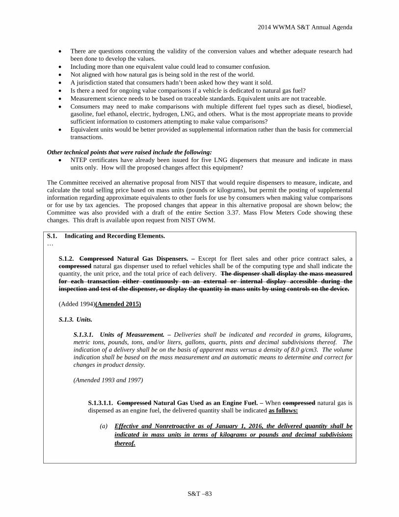
2014 WWMA S&T Annual Agenda
S&T –83
• There are questions concerning the validity of the conversion values and whether adequate research had been done to develop the values.
• Including more than one equivalent value could lead to consumer confusion. • Not aligned with how natural gas is being sold in the rest of the world. • A jurisdiction stated that consumers hadn’t been asked how they want it sold. • Is there a need for ongoing value comparisons if a vehicle is dedicated to natural gas fuel? • Measurement science needs to be based on traceable standards. Equivalent units are not traceable. • Consumers may need to make comparisons with multiple different fuel types such as diesel, biodiesel,
gasoline, fuel ethanol, electric, hydrogen, LNG, and others. What is the most appropriate means to provide sufficient information to customers attempting to make value comparisons?
• Equivalent units would be better provided as supplemental information rather than the basis for commercial transactions.
Other technical points that were raised include the following:
• NTEP certificates have already been issued for five LNG dispensers that measure and indicate in mass units only. How will the proposed changes affect this equipment?
The Committee received an alternative proposal from NIST that would require dispensers to measure, indicate, and calculate the total selling price based on mass units (pounds or kilograms), but permit the posting of supplemental information regarding approximate equivalents to other fuels for use by consumers when making value comparisons or for use by tax agencies. The proposed changes that appear in this alternative proposal are shown below; the Committee was also provided with a draft of the entire Section 3.37. Mass Flow Meters Code showing these changes. This draft is available upon request from NIST OWM.
S.1. Indicating and Recording Elements. …
S.1.2. Compressed Natural Gas Dispensers. – Except for fleet sales and other price contract sales, a compressed natural gas dispenser used to refuel vehicles shall be of the computing type and shall indicate the quantity, the unit price, and the total price of each delivery. The dispenser shall display the mass measured for each transaction either continuously on an external or internal display accessible during the inspection and test of the dispenser, or display the quantity in mass units by using controls on the device.
(Added 1994)(Amended 2015)
S.1.3. Units.
S.1.3.1. Units of Measurement. – Deliveries shall be indicated and recorded in grams, kilograms, metric tons, pounds, tons, and/or liters, gallons, quarts, pints and decimal subdivisions thereof. The indication of a delivery shall be on the basis of apparent mass versus a density of 8.0 g/cm3. The volume indication shall be based on the mass measurement and an automatic means to determine and correct for changes in product density.
(Amended 1993 and 1997)
S.1.3.1.1. Compressed Natural Gas Used as an Engine Fuel. – When compressed natural gas is dispensed as an engine fuel, the delivered quantity shall be indicated as follows:
(a) Effective and Nonretroactive as of January 1, 2016, the delivered quantity shall be indicated in mass units in terms of kilograms or pounds and decimal subdivisions thereof.
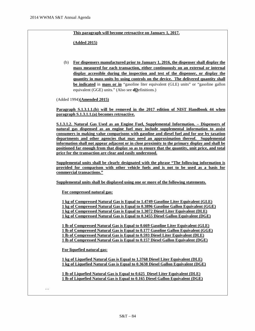
2014 WWMA S&T Annual Agenda
S&T – 84
This paragraph will become retroactive on January 1, 2017.
(Added 2015)
(b) For dispensers manufactured prior to January 1, 2016, the dispenser shall display the mass measured for each transaction, either continuously on an external or internal display accessible during the inspection and test of the dispenser, or display the quantity in mass units by using controls on the device. The delivered quantity shall be indicated in mass or in “gasoline liter equivalent (GLE) units” or “gasoline gallon equivalent (GGE) units.” (Also see dDefinitions.)
(Added 1994)(Amended 2015)
Paragraph S.1.3.1.1.(b) will be removed in the 2017 edition of NIST Handbook 44 when paragraph S.1.3.1.1.(a) becomes retroactive.
S.1.3.1.2. Natural Gas Used as an Engine Fuel, Supplemental Information. – Dispensers of natural gas dispensed as an engine fuel may include supplemental information to assist consumers in making value comparisons with gasoline and diesel fuel and for use by taxation departments and other agencies that may need an approximation thereof. Supplemental information shall not appear adjacent or in close proximity to the primary display and shall be positioned far enough from that display so as to ensure that the quantity, unit price, and total price for the transaction are clear and easily understood.
Supplemental units shall be clearly designated with the phrase “The following information is provided for comparison with other vehicle fuels and is not to be used as a basis for commercial transactions.”
Supplemental units shall be displayed using one or more of the following statements.
For compressed natural gas: 1 kg of Compressed Natural Gas is Equal to 1.4749 Gasoline Liter Equivalent (GLE) 1 kg of Compressed Natural Gas is Equal to 0.3896 Gasoline Gallon Equivalent (GGE) 1 kg of Compressed Natural Gas is Equal to 1.3072 Diesel Liter Equivalent (DLE) 1 kg of Compressed Natural Gas is Equal to 0.3455 Diesel Gallon Equivalent (DGE) 1 lb of Compressed Natural Gas is Equal to 0.669 Gasoline Liter Equivalent (GLE) 1 lb of Compressed Natural Gas is Equal to 0.177 Gasoline Gallon Equivalent (GGE) 1 lb of Compressed Natural Gas is Equal to 0.593 Diesel Liter Equivalent (DLE) 1 lb of Compressed Natural Gas is Equal to 0.157 Diesel Gallon Equivalent (DGE) For liquefied natural gas: 1 kg of Liquefied Natural Gas is Equal to 1.3768 Diesel Liter Equivalent (DLE) 1 kg of Liquefied Natural Gas is Equal to 0.3638 Diesel Gallon Equivalent (DGE) 1 lb of Liquefied Natural Gas is Equal to 0.625 Diesel Liter Equivalent (DLE) 1 lb of Liquefied Natural Gas is Equal to 0.165 Diesel Gallon Equivalent (DGE)
…
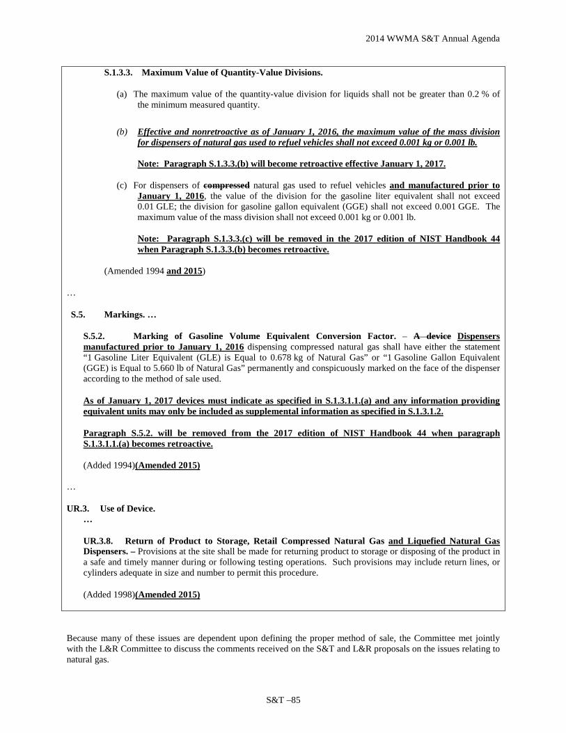
2014 WWMA S&T Annual Agenda
S&T –85
S.1.3.3. Maximum Value of Quantity-Value Divisions.
(a) The maximum value of the quantity-value division for liquids shall not be greater than 0.2 % of the minimum measured quantity.
(b) Effective and nonretroactive as of January 1, 2016, the maximum value of the mass division for dispensers of natural gas used to refuel vehicles shall not exceed 0.001 kg or 0.001 lb.
Note: Paragraph S.1.3.3.(b) will become retroactive effective January 1, 2017.
(c) For dispensers of compressed natural gas used to refuel vehicles and manufactured prior to January 1, 2016, the value of the division for the gasoline liter equivalent shall not exceed 0.01 GLE; the division for gasoline gallon equivalent (GGE) shall not exceed 0.001 GGE. The maximum value of the mass division shall not exceed 0.001 kg or 0.001 lb.
Note: Paragraph S.1.3.3.(c) will be removed in the 2017 edition of NIST Handbook 44 when Paragraph S.1.3.3.(b) becomes retroactive.
(Amended 1994 and 2015)
…
S.5. Markings. …
S.5.2. Marking of Gasoline Volume Equivalent Conversion Factor. – A device Dispensers manufactured prior to January 1, 2016 dispensing compressed natural gas shall have either the statement “1 Gasoline Liter Equivalent (GLE) is Equal to 0.678 kg of Natural Gas” or “1 Gasoline Gallon Equivalent (GGE) is Equal to 5.660 lb of Natural Gas” permanently and conspicuously marked on the face of the dispenser according to the method of sale used.
As of January 1, 2017 devices must indicate as specified in S.1.3.1.1.(a) and any information providing equivalent units may only be included as supplemental information as specified in S.1.3.1.2.
Paragraph S.5.2. will be removed from the 2017 edition of NIST Handbook 44 when paragraph S.1.3.1.1.(a) becomes retroactive.
(Added 1994)(Amended 2015)
…
UR.3. Use of Device. …
UR.3.8. Return of Product to Storage, Retail Compressed Natural Gas and Liquefied Natural Gas Dispensers. – Provisions at the site shall be made for returning product to storage or disposing of the product in a safe and timely manner during or following testing operations. Such provisions may include return lines, or cylinders adequate in size and number to permit this procedure.
(Added 1998)(Amended 2015)
Because many of these issues are dependent upon defining the proper method of sale, the Committee met jointly with the L&R Committee to discuss the comments received on the S&T and L&R proposals on the issues relating to natural gas.

2014 WWMA S&T Annual Agenda
S&T – 86
The Committee identified the method of sale by mass versus equivalent volumetric units as the most significant concern based on comments heard on this proposal. In addition to support for this proposal, there were also concerns regarding the use of the word “approximately” for labeling purposes; “multiple equivalent units” labeled on the same dispenser; “tax issues;” and other less commonly expressed issues. It was decided to eliminate the labeling altogether and not delay the effective date, thereby, addressing all three concerns. Consequently, the Committee agreed to delete paragraphs S.5.2., S.5.3., UR.3.1.1., and UR.3.1.2. in their entirety from the proposal and paragraph S.5.2. from NIST Handbook 44.
Based upon the comments received and its deliberations, the Committee agreed to modify the Item Under Consideration shown in Publication 16 by deleting the following language:
S.5.2. Marking of Equivalent Conversion Factor for Compressed Natural Gas. – A device dispensing compressed natural gas shall have either the statements “1 Gasoline Liter Equivalent (GLE) is Approximately Equal to 0.678 kg of Compressed Natural Gas” and “1 Diesel Liter Equivalent (DLE) is Approximately Equal to 0.765 kg of Compressed Natural Gas” or the statements “1 Gasoline Gallon Equivalent (GGE) is Approximately Equal to 5.660 lb of Compressed Natural Gas” and “1 Diesel Gallon Equivalent (DGE) is Approximately Equal to 6.384 lb of Compressed Natural Gas” permanently and conspicuously marked on the face of the dispenser according to the method of sale used. (Added 1994, amended 2014) S.5.3. Marking of Diesel Volume Equivalent Conversion Factor for Liquefied Natural Gas. – A device dispensing liquefied natural gas shall have either the statement "1 Diesel Liter Equivalent (DLE) is Approximately Equal to 0.726 kg of Liquefied Natural Gas" or "1 Diesel Gallon Equivalent (DGE) is Approximately Equal to 6.059 lb of Liquefied Natural Gas" permanently and conspicuously marked on the face of the dispenser according to the method of sale used. (Added 2014)
UR.3.1.1. Marking of Equivalent Conversion Factor for Compressed Natural Gas. – A device dispensing compressed natural gas shall have either the statements “1 Gasoline Liter Equivalent (GLE) is Approximately Equal to 0.678 kg of Compressed Natural Gas” and “1 Diesel Liter Equivalent (DLE) is Approximately Equal to 0.765 kg of Compressed Natural Gas” or the statements “1 Gasoline Gallon Equivalent (GGE) is Approximately Equal to 5.660 lb of Compressed Natural Gas” and “1 Diesel Gallon Equivalent (DGE) is Approximately Equal to 6.384 lb of Compressed Natural Gas” permanently and conspicuously marked on the face of the dispenser according to the method of sale used. (Added 2014) UR.3.1.2. Marking of Equivalent Conversion Factor for Liquefied Natural Gas. - A device dispensing liquefied natural gas shall have either the statement "1 Diesel Liter Equivalent (DLE) is Approximately Equal to 0.726 kg of Liquefied Natural Gas" or "1 Diesel Gallon Equivalent (DGE) is Approximately Equal to 6.059 lb of Liquefied Natural Gas" permanently and conspicuously marked on the face of the dispenser according to the method of sale used. (Added 2014)
Regional Associations Comments: The WWMA heard no support on this item and recommended that it be Withdrawn. The intent of the proposal is to make cost comparisons between diesel fuel and natural gas. The WWMA believes this proposal doesn’t meet the historic definition of “Cost Comparison” and shouldn’t be a specification item in Handbook 44. The WWMA believes Natural Gas should be sold in traceable units and not artificial equivalent units. The NCWM Natural Gas Steering Committee should take into consideration global method of sale and advertising of LNG/CNG. The WWMA believes the urgency of this issue demands quick action by the NCWM because these devices are growing quickly in the market place. SWMA heard comments in open hearing indicating that Item 337-5 was proposed to further clarify Item 337-4. The Committee agreed with comments heard that 337-4 continue to be a developing item. Based on the comments received the Committee believed this item may be more appropriate as a user requirement and should be kept as

2014 WWMA S&T Annual Agenda
S&T –87
developmental status with review by Steering Committee. The Committee believed that the identity should be indicated in a single unit. The SWMA S&T and L&R Committees met jointly to discuss CNG and LNG items on both agendas
With respect to the Item Under Consideration, the Committee received additional letters of support from: • ANGI Energy Systems, • California Natural Gas Vehicle Coalition, • Maine Clean Communities = MC2, • Sacramento Clean Cities Coalition, and • Questar Gas Company
NEWMA agreed to recommend the status of this item be changed to “Informational” after the failed Committee failed to receive a motion to recommend it as a Voting item. The “Informational” status was recommended to address the continued debate on marketing, tax issues, conversion values, testing and MOS.
CWMA L&R and S&T committees met jointly, and concur the items have merit, but questions and concerns over accuracy of this final proposal still remain. Both committees agreed to move the item forward as an Information item. During the L&R Committee’s work session, discussion took place regarding the inconsistency in language in the method of sale in L&R item 232-3, section 2.27.2. compared to the method of sale with L&R item 237-2 section 3.11.2.1. Additionally, the committee discussed including the same number of significant digits in the conversions specified in the DGE and DLE equivalent values. The Chairman of the CWMA L&R Committee communicated these two concerns to the Chairman of the NCWM Natural Gas Steering Committee. Based on discussion heard during a joint L & R and S & T committee meeting CWMA recommend this be changed to an Informational item.
Item 337-1
Summary of comments considered by the regional committee (in writing or during the open hearings): Mahesh Albuquerque, Chair of the Natural Gas Steering Committee (NGSC), provided an update of their most recent meeting, September 4, 2014. The NGSC is continuing to review feedback and is reviewing data on conversion factors. Additionally, the NGSC intends to provide and update to the proposal at the 2015 Interim Meeting. Several regulators offered comments (pro and con) similar to what is contained in the Background/Discussion of the report. Item as proposed by the regional committee: (If different than agenda item) Committee recommendation to the region:
Voting Item on the NCWM Agenda Information Item on the NCWM Agenda Withdraw the Item from the NCWM Agenda (In the case of new items, do not forward to NCWM) Developing Item on the NCWM Agenda (To be developed by source)
Reasons for the committee recommendation: The WWMA S&T Committee acknowledges and appreciates the work and advice of the NGSC. The WWMA S&T Committee recommends this be an Informational item on the 2015 NCWM Interim Agenda. Brett Barry, speaking on behalf of the NGSC, stated that they will provide an update in advance of the 2015 Interim to allow a thorough review of changes to the proposal. The WWMA S&T Committee recommends that several areas should be considered by the NGSC and NCWM S&T Committee. These include the following:
• The NIST Alternate Proposal; • A customer selectable indication for mass/DGE/GGE with a grandfather date of 20XX for existing
equipment; and • If GGE should be allowed for high flow rate sales of CNG, in other words, should high flow rate sales of
CNG be limited only to DGE?
COMPLETE SECTION BELOW FOLLOWING VOTING SESSION
Final updated or revised proposal from the region: (If different than regional committee recommendation)

2014 WWMA S&T Annual Agenda
S&T – 88
Regional recommendation to NCWM for item status: Voting Item on the NCWM Agenda Information Item on the NCWM Agenda Withdraw the Item from the NCWM Agenda (In the case of new items, do not forward to NCWM) Developing Item on the NCWM Agenda (To be developed by source) Unable to consider at this time (Provide explanation in the “Additional Comments” section below)
Regional Report to NCWM: Please provide your report in this section exactly how you want it to appear in the NCWM reports to represent your region’s considerations, support or opposition, and recommendations. This will replace any previous reports from your region on this item. During open hearing at the 2014 WWMA Annual Meeting an update on the Natural Gas Steering Committee was provided and comments were heard (pro and con) for this item similar to what has been offered previously. The WWMA agrees that this topic needs to be addressed and resolved; therefore it should remain as an Information Item on the NCWM Agenda. The WWMA S&T Committee offers the recommendations of 1. Consideration of the NIST Proposal, 2. Possibility of a customer selectable unit and 3. Determination of GGE to low volume sales and DGE to high volume sales. During the S&T Committee voting session it was motioned, seconded and approved that comments presented during the L&R Committee voting session be adopted. The comments included a call for vote by those in support of sale in mass versus those in support of sale by equivalent unit. A show of hands was recorded by the Parliamentarian and indicated those in favor of mass to be 23 and those in favor of equivalent unit to be 12. These and other letters, presentations and data may have been part of the committee’s consideration. Please refer to http://ncwm.net/meetings/annual/publication-16 to review these documents.
337-2 D S.3.6. Automatic Density Compensation
Source: NCWM Natural Gas Steering Committee (2014 Interim Meeting)
Source: This is a new item (2014) that originated from the NCWM Natural Gas Steering Committee (NGSC) as a result of its deliberations January through March 2014 on agenda item 337-1 (an alternative proposal for defining and establishing legal metrology requirements for quantity indications and markings on a device when CNG and LNG are dispensed and sold as engine fuel in volume equivalent units). The NGSC recommends the proposal as a developing item to allow additional time for the NCWM NTEP Measuring Sector and Measuring Laboratories to fully vet the newly proposed modifications to HB 44 Mass Flow Meters Code paragraph S.3.6. Automatic Density Correction.
Purpose: Provide a starting point for work identified in March 2014 by the NGSC and S&T Committee that is necessary to fully address legal metrology requirements for LNG retail and wholesale applications.
Item Under Consideration: Amend NIST Handbook 44 Mass Flow Meters Code paragraph S.3.6. as follows:
S.3.6. Automatic Density Correction.
(a) An automatic means to determine and correct for changes in product density shall be incorporated in any mass flow metering system that is affected by changes in the density of the product being measured. (b) Volume-measuring devices with automatic temperature compensation used to measure liquefied natural gas as a motor vehicle engine fuel shall be equipped with an automatic means to determine and

2014 WWMA S&T Annual Agenda
S&T –89
correct for changes in product density due to changes in the temperature, pressure, and composition of the product. (Amended 1994 and 1997, and 201X)
Background/Discussion: After the January 2014 NCWM Interim Meeting, the NGSC and S&T Committee received input from Mr. Dmitri Karimov (Liquid Controls Corporation, LLC and a member of the NGSC), who proposed to differentiate between CNG and LNG in the requirements of paragraph S.3.6 “Automatic Density Correction” when using volumetric devices. Mr. Karimov indicated that density calculations of LNG when measured using a volumetric device, require temperature determination only. CNG devices will not be allowed to use indirect mass measurement in Mr. Karimov’s proposal. Mr. Karimov’s provided the NGSC and S&T Committee with the following points as rationale for the proposed changes to paragraph S.3.6. :
• The requirements for volume‐measuring devices were developed in 1994 and 1997 for CNG based on hydrocarbon gas vapor code. See the attached NCWM final reports at the end of the document.
• The concerns might be valid for CNG but not for LNG. For LNG, only temperature input is required to
calculate mass value.
• Based on the most recent changes to the Mass Flow Meters Code by the NGSC, indirect mass measurement is proposed to be allowed for LNG but not CNG, so S.3.6 needs to be modified.
• CNG and LNG mass flow meters (Coriolis) with automatic density correction will be covered by paragraph
S.3.6.(a)
• LNG volume‐measuring devices (such as orifice plate and turbine meters) will be covered by paragraph S.3.6.(b) since indirect mass measurement for CNG is no longer allowed under the proposal by the NGSC.
• CNG (being gas) is very compressible, so pressure is a significant influence factor in density calculation.
“Pressure” was added to S.3.6.(b) in 1997 because at that time the paragraph was relied upon only for CNG.
• LNG, on the other hand, is measured at very low pressure, and – being liquid‐ is not compressible at the pressures at which it is measured. Pressure effect on density of LNG is therefore negligible. See the table below where Mr. Karimov generated data on LNG density changes using the NIST REFPROP database.
• Per documentation received by the NGSC from the Clean Vehicle Education Foundation, the composition of the natural gas remained virtually unchanged over the last 21 years. Therefore, volumetric devices for LNG could use fixed composition in density calculations as per ASTM D4784 Clause 2.1 (see below).
• Finally, indirect mass measurement volumetric devices undergo type evaluation, and only those devices meeting accuracy requirements through proper density calculations are approved.
Supporting documentation: ASTM D4784 – 93 (Reapproved 2010) Standard Specification for LNG Density Calculation Models ASTM D4784 provides models for density calculation.

2014 WWMA S&T Annual Agenda
S&T – 90
2. Significance an d Use
2.1 The models in this specification can be used to calculate the density of saturated liquid natural gas in the temperature range 90 to 120 K. The estimated uncertainty for the density calculations is ± 0.1 %. The restrictions on composition of the liquefied natural gas are:
methane nitrogen n-butane i-butane pentanes
60 % or greater less than 4 % less than 4 % less than 4 % less than 2 %
Mr. Karimov also referenced excerpts from past NCWM Final Reports from 1994 and 1997. These excerpts are found in Appendix E to the Committee’s 2014 Interim Report. Listed below is the table Mr. Karimov generated on LNG density changes using the NIST REFPROP database. Mr. Karimov noted that density changes to LNG are negligible at 120 K with changes in pressure from the base pressure of 27.765 psi up to 200 psi.

2014 WWMA S&T Annual Agenda
S&T –91
Density Changes to LNG
Temperature1
(K) Pressure
(psia) Density
(lbMASS/gal) % Density Difference2
120 27.765 3.4208 0.000% 120 30 3.4209 ‐0.003% 120 35 3.4213 ‐0.015% 120 40 3.4216 ‐0.023% 120 45 3.4219 ‐0.032% 120 50 3.4222 ‐0.041% 120 55 3.4225 ‐0.050% 120 60 3.4229 ‐0.061% 120 65 3.4232 ‐0.070% 120 70 3.4235 ‐0.079% 120 75 3.4238 ‐0.088% 120 80 3.4241 ‐0.096% 120 85 3.4245 ‐0.108% 120 90 3.4248 ‐0.117% 120 95 3.4251 ‐0.126% 120 100 3.4254 ‐0.134% 120 105 3.4257 ‐0.143% 120 110 3.4261 ‐0.155% 120 115 3.4264 ‐0.164% 120 120 3.4267 ‐0.172% 120 125 3.427 ‐0.181% 120 130 3.4273 ‐0.190% 120 135 3.4276 ‐0.199% 120 140 3.428 ‐0.210% 120 145 3.4283 ‐0.219% 120 150 3.4286 ‐0.228% 120 155 3.4289 ‐0.237% 120 160 3.4292 ‐0.246% 120 165 3.4295 ‐0.254% 120 170 3.4298 ‐0.263% 120 175 3.4302 ‐0.275% 120 180 3.4305 ‐0.284% 120 185 3.4308 ‐0.292% 120 190 3.4311 ‐0.301% 120 195 3.4314 ‐0.310% 120 200 3.4317 ‐0.319%
1120 K (-153 °C) (-243 °F) 2Percent difference in product (pure methane) density is based on calculated variations to the base pressure of 27.765 psi using NIST REFPROP
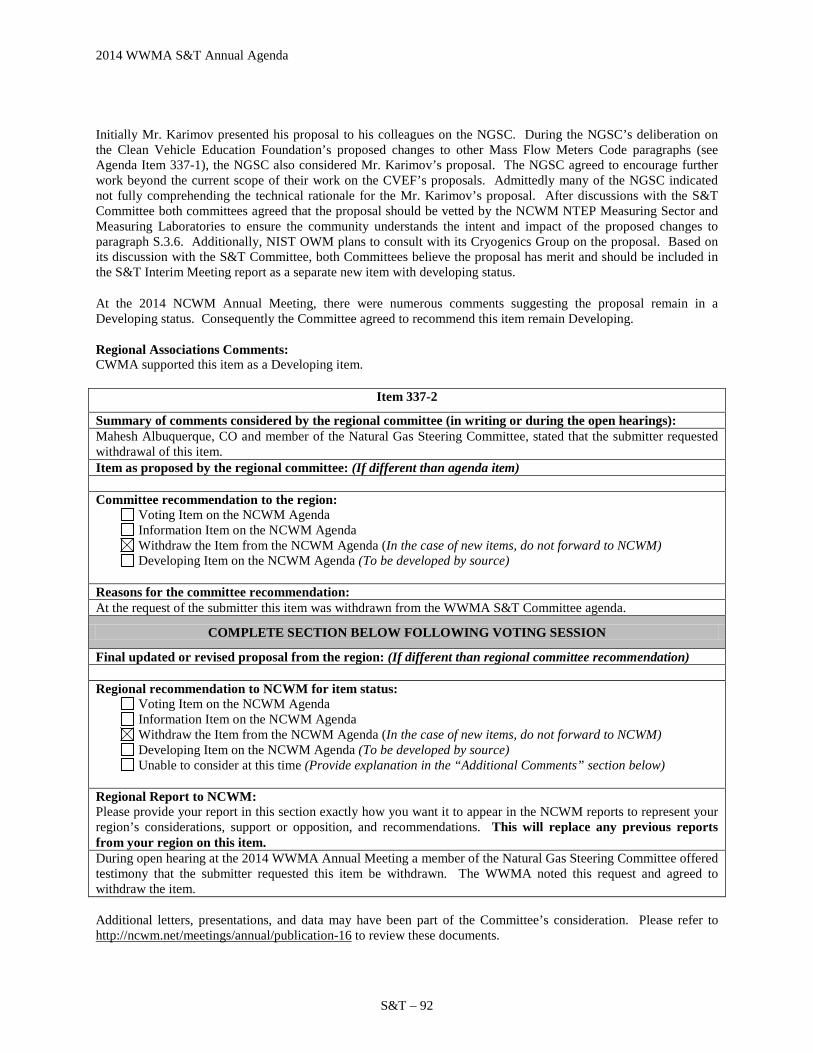
2014 WWMA S&T Annual Agenda
S&T – 92
Initially Mr. Karimov presented his proposal to his colleagues on the NGSC. During the NGSC’s deliberation on the Clean Vehicle Education Foundation’s proposed changes to other Mass Flow Meters Code paragraphs (see Agenda Item 337-1), the NGSC also considered Mr. Karimov’s proposal. The NGSC agreed to encourage further work beyond the current scope of their work on the CVEF’s proposals. Admittedly many of the NGSC indicated not fully comprehending the technical rationale for the Mr. Karimov’s proposal. After discussions with the S&T Committee both committees agreed that the proposal should be vetted by the NCWM NTEP Measuring Sector and Measuring Laboratories to ensure the community understands the intent and impact of the proposed changes to paragraph S.3.6. Additionally, NIST OWM plans to consult with its Cryogenics Group on the proposal. Based on its discussion with the S&T Committee, both Committees believe the proposal has merit and should be included in the S&T Interim Meeting report as a separate new item with developing status.
At the 2014 NCWM Annual Meeting, there were numerous comments suggesting the proposal remain in a Developing status. Consequently the Committee agreed to recommend this item remain Developing. Regional Associations Comments: CWMA supported this item as a Developing item.
Item 337-2
Summary of comments considered by the regional committee (in writing or during the open hearings): Mahesh Albuquerque, CO and member of the Natural Gas Steering Committee, stated that the submitter requested withdrawal of this item. Item as proposed by the regional committee: (If different than agenda item) Committee recommendation to the region:
Voting Item on the NCWM Agenda Information Item on the NCWM Agenda Withdraw the Item from the NCWM Agenda (In the case of new items, do not forward to NCWM) Developing Item on the NCWM Agenda (To be developed by source)
Reasons for the committee recommendation: At the request of the submitter this item was withdrawn from the WWMA S&T Committee agenda.
COMPLETE SECTION BELOW FOLLOWING VOTING SESSION
Final updated or revised proposal from the region: (If different than regional committee recommendation) Regional recommendation to NCWM for item status:
Voting Item on the NCWM Agenda Information Item on the NCWM Agenda Withdraw the Item from the NCWM Agenda (In the case of new items, do not forward to NCWM) Developing Item on the NCWM Agenda (To be developed by source) Unable to consider at this time (Provide explanation in the “Additional Comments” section below)
Regional Report to NCWM: Please provide your report in this section exactly how you want it to appear in the NCWM reports to represent your region’s considerations, support or opposition, and recommendations. This will replace any previous reports from your region on this item. During open hearing at the 2014 WWMA Annual Meeting a member of the Natural Gas Steering Committee offered testimony that the submitter requested this item be withdrawn. The WWMA noted this request and agreed to withdraw the item. Additional letters, presentations, and data may have been part of the Committee’s consideration. Please refer to http://ncwm.net/meetings/annual/publication-16 to review these documents.

2014 WWMA S&T Annual Agenda
S&T –93
337-3 N.3. Test Drafts (NEW)
Source: Endress + Hauser Flowtec AG USA Purpose: Allow transfer standard meters to be used to test and place into service dispensers and delivery system flow meters.
Item Under Consideration: Amend NIST Handbook 44 LPG and Anhydrous Ammonia Liquid-Measuring Devices as follows:
N.3. Test Drafts. – N.3.1 Minimum Test - Test drafts should be equal to at least the amount delivered by the device in one minute at its normal discharge rate. (Amended 1982) N.3.2. Transfer Standard Test. – When comparing a meter with a calibrated transfer standard, the test draft shall be equal to at least the amount delivered by the device in 2 minutes at its maximum discharge rate.
Background / Discussion: The use of transfer standards is recognized in Code sections 3.34 Cryogenic Liquid-Measuring Devices Code and 3.38 Carbon Dioxide Liquid-Measuring Devices Code and 3.39 Hydrogen Gas-Measuring Devices – Tentative Code. Field evaluation of LPG meters and CNG dispensers and LNG dispensers is very difficult using volumetric and gravimetric field standards and methods. The tolerances for these applications are such that using transfer meter standards are more efficient and safer. With CNG and LNG and LPG applications, the transfer standard meters are placed in-line with the delivery system as it is used to fill tanks and vehicles. The use of transfer standards eliminates return to storage issues. The use of transfer standard meters is easier and faster compared to the use of traditional field standards. The cost of using transfer standards and transporting them is much less than the cost of traditional field provers and standards. Recognition in Handbook 44 will enable States to allow transfer standard meters to place systems into service and for field enforcement. Volumetric field provers and gravimetric field proving are susceptible to environmental influences. The State of Colorado uses a master meter to test propane delivery truck meters. The State of Nebraska has used a mass flow meter to test agricultural chemical meters. In some applications, transfer standard meters are not more accurate than the meters used in the dispenser. For that reason, longer test drafts and possibly more tests need to be run. The State of California is purported to have conducted a short study of master meters in the past. The conclusion did not lead to wide adoption of the practice. However, the State of California uses a mass flow meter as a master meter for carbon dioxide flowmeter enforcement. Mass Flow Meters user requirement U.R.3.8. Return of Product to Storage, Retail Compressed Natural Gas Dispensers requires that the natural gas which is delivered into the test container must be returned to storage. This is difficult and most often not complied with when the test vessel contents are released to atmosphere. The S&T Committee might also consider amending Sections 3.30 Liquid-Measuring Devices Code and 3.31 Vehicle-Tank Meters Code to allow transfer standard meters.

2014 WWMA S&T Annual Agenda
S&T – 94
Item 337-3
Summary of comments considered by the regional committee (in writing or during the open hearings): Gordon Johnson, Gilbarco, stated that the need for a master meter test is present and would solve several issues in regard to these types of tests. Carol Hockert, NIST OWM, stated that uncertainties of this type of measurement need to be fully evaluated prior to adopting any test methods. Item as proposed by the regional committee: (If different than agenda item) Committee recommendation to the region:
Voting Item on the NCWM Agenda Information Item on the NCWM Agenda Withdraw the Item from the NCWM Agenda (In the case of new items, do not forward to NCWM) Developing Item on the NCWM Agenda (To be developed by source)
Reasons for the committee recommendation: The WWMA S&T Committee feels that additional information and establishment of test procedures and data is needed to further evaluate the proposal.
COMPLETE SECTION BELOW FOLLOWING VOTING SESSION
Final updated or revised proposal from the region: (If different than regional committee recommendation) Regional recommendation to NCWM for item status:
Voting Item on the NCWM Agenda Information Item on the NCWM Agenda Withdraw the Item from the NCWM Agenda (In the case of new items, do not forward to NCWM) Developing Item on the NCWM Agenda (To be developed by source) Unable to consider at this time (Provide explanation in the “Additional Comments” section below)
Regional Report to NCWM: Please provide your report in this section exactly how you want it to appear in the NCWM reports to represent your region’s considerations, support or opposition, and recommendations. This will replace any previous reports from your region on this item. At the 2014 WWMA Annual Meeting testimony was presented that this type of technology would more easily facilitate inspections. However, it was also stated that a more comprehensive evaluation of the equipment and testing procedure, including the associated uncertainty, be performed. The WWMA agreed that this type of technology would be useful but it should be a Developing Item to allow the submitter to provide a more complete analysis.
354 TAXIMETERS
354-1 S.1.1. 1. Recording Elements. (NEW)
Source: NIST USNWG on Taximeters
Purpose: Ensure that customers can receive a printed receipt detailing charges for taximeters put in service after a specified date.

2014 WWMA S&T Annual Agenda
S&T –95
Item Under Consideration: Amend NIST Handbook 44 Taximeter Code as follows:
S.1.1. General. – A taximeter shall be equipped with a primary indicating element and may be equipped with a recording element. (Amended 1988 and 20XX)
S.1.1.1. Recording Elements. – A receipt providing information as required in S.1.9. Recorded Representations shall be available from a taximeter or taximeter system through an integral or separate recording element for all transactions conducted. [Nonretroactive January 1, 201X] (Added 201X)
Background / Discussion: Transactions involving for-hire vehicles may include multiple charges and as a result be somewhat complex. Total charges resulting from taxi services in some jurisdictions can include the fare based on time and distance traveled) as well as extras and other additional charges. Those extras and additional charges may include charges for additional passengers, transportation of luggage, tolls, surcharges, and taxes. In some locations, passenger(s) are presented with offers for other services unrelated to the taxi service during the trip, such as the purchase of tickets for theater or shows. If purchased, the cost of these services may be included as part of the overall charge in the transaction.
The USNWG on Taximeters has noted that in many instances the interchange between passenger and the taxi driver is brief and that the passenger may not immediately comprehend fully all the details regarding a transaction. With a potential total cost to the passenger comprised of numerous charges, it is considered important that the customer (passenger) be able to receive a record of those charges as evidence of what was paid for. Requiring that a form of receipt (printed or electronic) be made available to the passenger when desired, will help to ensure that the customer is provided a record of expenses paid for, and as necessary documentation in cases where charges may be disputed.
Amending paragraph S.1.1. as shown will remove the existing optional provision for a recording element associated with a taximeter and the addition of a new S.1.1.1. will require that a form of receipt is capable of being produced by the taximeter system for all transactions (non-retroactively). Taximeter systems manufactured and placed in service prior to the effective date of the new paragraph S.1.1.1. will still be permitted, and will not be required to include a recording element however, those manufactured and placed into service after the effective date will be required to make a receipt available to the customer. It is intended that the non-retroactive status will provide device manufacturers ample time to comply with the proposed requirement. Requiring receipts from all taximeters may be considered onerous to taxi owners/operators that operate in areas that have very simple rate structures and where the total charges to the customer would possibly only include a fare based on distance and/or time. This burden will be mitigated however, by the non-retroactive status of the proposed new requirement.
Item 354-1
Summary of comments considered by the regional committee (in writing or during the open hearings): Keith Walsh, NYC Taxi Commission and member of USNWG on Taxi Meters, stated that this item has been in development for 3 years and is ready for voting status. Additionally, he commented that it is imperative that this item move through so that the W&M community can stay current with today’s environment. Item as proposed by the regional committee: (If different than agenda item) Committee recommendation to the region:
Voting Item on the NCWM Agenda Information Item on the NCWM Agenda Withdraw the Item from the NCWM Agenda (In the case of new items, do not forward to NCWM) Developing Item on the NCWM Agenda (To be developed by source)
Reasons for the committee recommendation:

2014 WWMA S&T Annual Agenda
S&T – 96
The WWMA S&T Committee acknowledges and appreciates the work and advice of the USNWG on Taxi Meters. The WWMA S&T Committee feels this item is fully developed and ready for a vote. Further, the Committee recommends that items 354-1, 354-2, 354-3, 354-4, and 354-5 be combined into one proposal.
COMPLETE SECTION BELOW FOLLOWING VOTING SESSION
Final updated or revised proposal from the region: (If different than regional committee recommendation) Regional recommendation to NCWM for item status:
Voting Item on the NCWM Agenda Information Item on the NCWM Agenda Withdraw the Item from the NCWM Agenda (In the case of new items, do not forward to NCWM) Developing Item on the NCWM Agenda (To be developed by source) Unable to consider at this time (Provide explanation in the “Additional Comments” section below)
Regional Report to NCWM: Please provide your report in this section exactly how you want it to appear in the NCWM reports to represent your region’s considerations, support or opposition, and recommendations. This will replace any previous reports from your region on this item. During open hearings at the 2014 WWMA Annual Meeting a member of the USNWG on Taxi Meters have been in development for 3 years and is ready to be a Voting Item. Further, he stressed that it is imperative that these changes be adopted to ensure the W&M community stay current with today’s environment. No opposition to this item was presented. The WWMA recognizes the amount of work that has been done on this item and agrees that it is ready to be a Voting Item on the NCWM Agenda. Further, the WWMA recommends that 2014 WWMA S&T Committee items 354-1, 354-2, 354-3, 354-4, and 354-5 be combined into one proposal.
354-2 S.1.2. Advancement of Indicating Elements. (NEW)
Source: NIST USNWG on Taximeters
Purpose: Allow for the advancement of fare indication by the input of a flat rate where the local authority permits the use of flat rates and provides clarification that charges displayed on the taximeter other than fare may occur by a manual input or by an automatic means.
Item Under Consideration: Amend NIST Handbook 44 Taximeter Code as follows:
S.1.2. Advancement of Indicating Elements. – Except when a taximeter is being cleared, the fare charges displayed on the primary indicating and recording elements shall be susceptible of advancement only by:
a). the movement of the vehicle; b). by the time mechanism; c). a combination of both a) and b*); or d). the entry of a monetary amount associated with a flat rate or negotiated rate where permitted.
Advancement of the indications for charges, other than fare may occur through manual or automatic means. * The advancement of fare may occur by either the movement of the vehicle or by the time mechanism but shall not occur by both of these means operating simultaneously (see also S.4. Interference). (Amended 1988, and 201X)
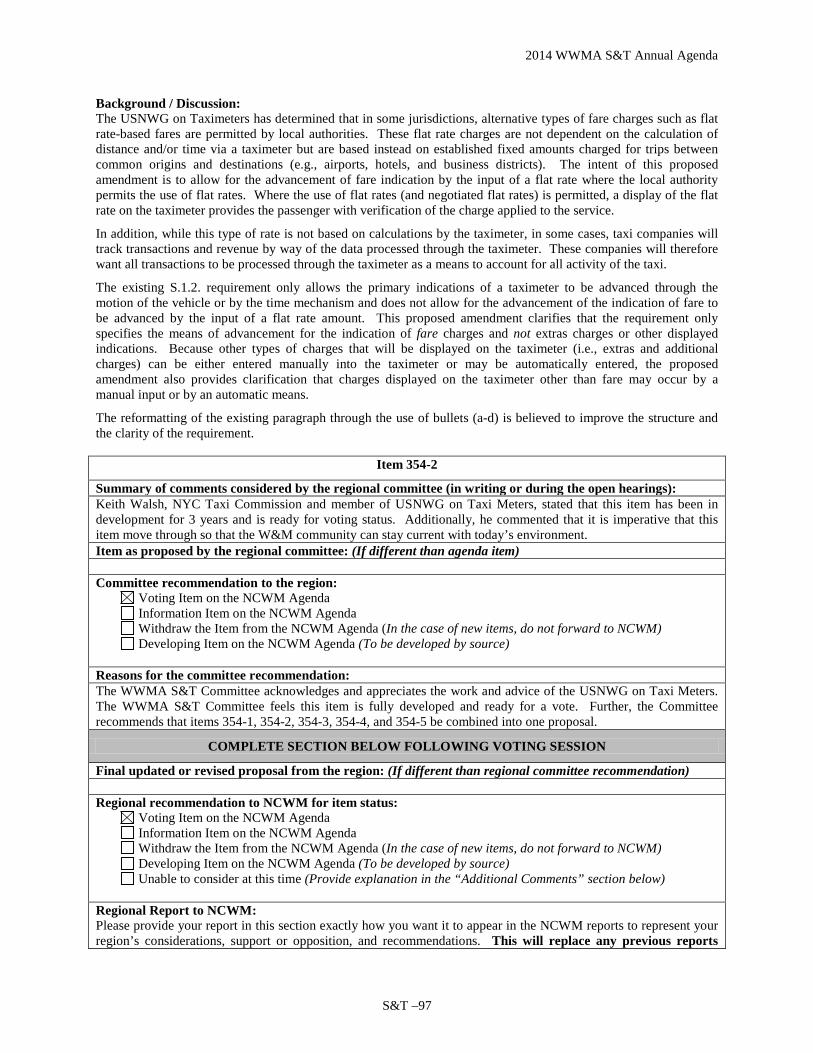
2014 WWMA S&T Annual Agenda
S&T –97
Background / Discussion: The USNWG on Taximeters has determined that in some jurisdictions, alternative types of fare charges such as flat rate-based fares are permitted by local authorities. These flat rate charges are not dependent on the calculation of distance and/or time via a taximeter but are based instead on established fixed amounts charged for trips between common origins and destinations (e.g., airports, hotels, and business districts). The intent of this proposed amendment is to allow for the advancement of fare indication by the input of a flat rate where the local authority permits the use of flat rates. Where the use of flat rates (and negotiated flat rates) is permitted, a display of the flat rate on the taximeter provides the passenger with verification of the charge applied to the service.
In addition, while this type of rate is not based on calculations by the taximeter, in some cases, taxi companies will track transactions and revenue by way of the data processed through the taximeter. These companies will therefore want all transactions to be processed through the taximeter as a means to account for all activity of the taxi.
The existing S.1.2. requirement only allows the primary indications of a taximeter to be advanced through the motion of the vehicle or by the time mechanism and does not allow for the advancement of the indication of fare to be advanced by the input of a flat rate amount. This proposed amendment clarifies that the requirement only specifies the means of advancement for the indication of fare charges and not extras charges or other displayed indications. Because other types of charges that will be displayed on the taximeter (i.e., extras and additional charges) can be either entered manually into the taximeter or may be automatically entered, the proposed amendment also provides clarification that charges displayed on the taximeter other than fare may occur by a manual input or by an automatic means.
The reformatting of the existing paragraph through the use of bullets (a-d) is believed to improve the structure and the clarity of the requirement.
Item 354-2
Summary of comments considered by the regional committee (in writing or during the open hearings): Keith Walsh, NYC Taxi Commission and member of USNWG on Taxi Meters, stated that this item has been in development for 3 years and is ready for voting status. Additionally, he commented that it is imperative that this item move through so that the W&M community can stay current with today’s environment. Item as proposed by the regional committee: (If different than agenda item) Committee recommendation to the region:
Voting Item on the NCWM Agenda Information Item on the NCWM Agenda Withdraw the Item from the NCWM Agenda (In the case of new items, do not forward to NCWM) Developing Item on the NCWM Agenda (To be developed by source)
Reasons for the committee recommendation: The WWMA S&T Committee acknowledges and appreciates the work and advice of the USNWG on Taxi Meters. The WWMA S&T Committee feels this item is fully developed and ready for a vote. Further, the Committee recommends that items 354-1, 354-2, 354-3, 354-4, and 354-5 be combined into one proposal.
COMPLETE SECTION BELOW FOLLOWING VOTING SESSION
Final updated or revised proposal from the region: (If different than regional committee recommendation) Regional recommendation to NCWM for item status:
Voting Item on the NCWM Agenda Information Item on the NCWM Agenda Withdraw the Item from the NCWM Agenda (In the case of new items, do not forward to NCWM) Developing Item on the NCWM Agenda (To be developed by source) Unable to consider at this time (Provide explanation in the “Additional Comments” section below)
Regional Report to NCWM: Please provide your report in this section exactly how you want it to appear in the NCWM reports to represent your region’s considerations, support or opposition, and recommendations. This will replace any previous reports
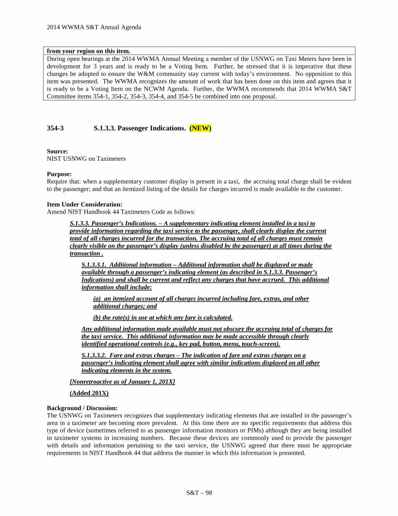
2014 WWMA S&T Annual Agenda
S&T – 98
from your region on this item. During open hearings at the 2014 WWMA Annual Meeting a member of the USNWG on Taxi Meters have been in development for 3 years and is ready to be a Voting Item. Further, he stressed that it is imperative that these changes be adopted to ensure the W&M community stay current with today’s environment. No opposition to this item was presented. The WWMA recognizes the amount of work that has been done on this item and agrees that it is ready to be a Voting Item on the NCWM Agenda. Further, the WWMA recommends that 2014 WWMA S&T Committee items 354-1, 354-2, 354-3, 354-4, and 354-5 be combined into one proposal.
354-3 S.1.3.3. Passenger Indications. (NEW)
Source: NIST USNWG on Taximeters
Purpose: Require that: when a supplementary customer display is present in a taxi, the accruing total charge shall be evident to the passenger; and that an itemized listing of the details for charges incurred is made available to the customer.
Item Under Consideration: Amend NIST Handbook 44 Taximeters Code as follows:
S.1.3.3. Passenger’s Indications. – A supplementary indicating element installed in a taxi to provide information regarding the taxi service to the passenger, shall clearly display the current total of all charges incurred for the transaction. The accruing total of all charges must remain clearly visible on the passenger’s display (unless disabled by the passenger) at all times during the transaction .
S.1.3.3.1. Additional information – Additional information shall be displayed or made available through a passenger’s indicating element (as described in S.1.3.3. Passenger’s Indications) and shall be current and reflect any charges that have accrued. This additional information shall include:
(a) an itemized account of all charges incurred including fare, extras, and other additional charges; and
(b) the rate(s) in use at which any fare is calculated.
Any additional information made available must not obscure the accruing total of charges for the taxi service. This additional information may be made accessible through clearly identified operational controls (e.g., key pad, button, menu, touch-screen).
S.1.3.3.2. Fare and extras charges – The indication of fare and extras charges on a passenger’s indicating element shall agree with similar indications displayed on all other indicating elements in the system.
[Nonretroactive as of January 1, 201X]
(Added 201X) Background / Discussion: The USNWG on Taximeters recognizes that supplementary indicating elements that are installed in the passenger’s area in a taximeter are becoming more prevalent. At this time there are no specific requirements that address this type of device (sometimes referred to as passenger information monitors or PIMs) although they are being installed in taximeter systems in increasing numbers. Because these devices are commonly used to provide the passenger with details and information pertaining to the taxi service, the USNWG agreed that there must be appropriate requirements in NIST Handbook 44 that address the manner in which this information is presented.

2014 WWMA S&T Annual Agenda
S&T –99
The addition of the proposed new requirements S.1.3.3., S.1.3.3.1., and S.1.3.3.2. in the Taximeters Code provides specification requirements for this type of indicating element. These new paragraphs provide manufacturers with design criteria for new devices and provide regulatory authorities with requirements to ensure that the passenger is supplied with sufficient information necessary to verify the cost of the transportation service provided.
The USNWG on Taximeters considered the most important single data item for the passenger is the accruing total of all charges during the trip. In this proposal, this information is required to be clearly visible on the passenger’s display at all times during the trip. Itemized details of individual charges and other information of importance must be made available to the passenger via these passenger’s indicating elements. In consideration of the limited size of the typical display area on this type of device, information other than the accruing total of charges need not be displayed constantly but must be available to the customer by clearly marked means through the operational controls on the device.
Because the primary indicating element in a system (the taximeter) will display the fare and extras indications, any supplemental device that also displays these indications must be in agreement with the taximeter. To address this, the proposed new S.1.3.3.2. would require that the display of fare and extras charges is in agreement with those same indications as displayed on other indicating elements in the system.
Item 354-3
Summary of comments considered by the regional committee (in writing or during the open hearings): Keith Walsh, NYC Taxi Commission and member of USNWG on Taxi Meters, stated that this item has been in development for 3 years and is ready for voting status. Additionally, he commented that it is imperative that this item move through so that the W&M community can stay current with today’s environment. Item as proposed by the regional committee: (If different than agenda item) Committee recommendation to the region:
Voting Item on the NCWM Agenda Information Item on the NCWM Agenda Withdraw the Item from the NCWM Agenda (In the case of new items, do not forward to NCWM) Developing Item on the NCWM Agenda (To be developed by source)
Reasons for the committee recommendation: The WWMA S&T Committee acknowledges and appreciates the work and advice of the USNWG on Taxi Meters. The WWMA S&T Committee feels this item is fully developed and ready for a vote. Further, the Committee recommends that items 354-1, 354-2, 354-3, 354-4, and 354-5 be combined into one proposal.
COMPLETE SECTION BELOW FOLLOWING VOTING SESSION
Final updated or revised proposal from the region: (If different than regional committee recommendation) Regional recommendation to NCWM for item status:
Voting Item on the NCWM Agenda Information Item on the NCWM Agenda Withdraw the Item from the NCWM Agenda (In the case of new items, do not forward to NCWM) Developing Item on the NCWM Agenda (To be developed by source) Unable to consider at this time (Provide explanation in the “Additional Comments” section below)
Regional Report to NCWM: Please provide your report in this section exactly how you want it to appear in the NCWM reports to represent your region’s considerations, support or opposition, and recommendations. This will replace any previous reports from your region on this item. During open hearings at the 2014 WWMA Annual Meeting a member of the USNWG on Taxi Meters have been in development for 3 years and is ready to be a Voting Item. Further, he stressed that it is imperative that these changes be adopted to ensure the W&M community stay current with today’s environment. No opposition to this item was presented. The WWMA recognizes the amount of work that has been done on this item and agrees that it is ready to be a Voting Item on the NCWM Agenda. Further, the WWMA recommends that 2014 WWMA S&T Committee items 354-1, 354-2, 354-3, 354-4, and 354-5 be combined into one proposal.

2014 WWMA S&T Annual Agenda
S&T – 100
354-4 S.1.8. Protection of Indications. (NEW)
Source: NIST USNWG on Taximeters
Purpose: Update specifications to reflect present day technology.
Item Under Consideration: Amend NIST Handbook 44 Taximeters Code as follows:
S.1.8. Protection of Indications. – All indications of fare and extras shall be displayed through and entirely protected by glass or other suitable transparent material securely attached to the housing of the taximeter protected from unauthorized alteration or manipulation. (Amended 20XX)
Background / Discussion: This requirement was drafted when taximeters consisted of mechanical-type meters whose displays were much more susceptible to manipulation and are rarely (if ever) found to be still in service. The proposed amendment of S.1.8. serves to update this requirement with respect to current technology. Paragraph S.1.8. requires that taximeter indications should be protected from manipulation (accomplished relatively easily on mechanical-type indications) through physical means. Electronic/digital type indications are less subject to physical manipulation although, those indications could potentially be manipulated through electronic means.
Item 354-4
Summary of comments considered by the regional committee (in writing or during the open hearings): Keith Walsh, NYC Taxi Commission and member of USNWG on Taxi Meters, stated that this item has been in development for 3 years and is ready for voting status. Additionally, he commented that it is imperative that this item move through so that the W&M community can stay current with today’s environment. Item as proposed by the regional committee: (If different than agenda item) Committee recommendation to the region:
Voting Item on the NCWM Agenda Information Item on the NCWM Agenda Withdraw the Item from the NCWM Agenda (In the case of new items, do not forward to NCWM) Developing Item on the NCWM Agenda (To be developed by source)
Reasons for the committee recommendation: The WWMA S&T Committee acknowledges and appreciates the work and advice of the USNWG on Taxi Meters. The WWMA S&T Committee feels this item is fully developed and ready for a vote. Further, the Committee recommends that items 354-1, 354-2, 354-3, 354-4, and 354-5 be combined into one proposal.
COMPLETE SECTION BELOW FOLLOWING VOTING SESSION
Final updated or revised proposal from the region: (If different than regional committee recommendation) Regional recommendation to NCWM for item status:
Voting Item on the NCWM Agenda Information Item on the NCWM Agenda Withdraw the Item from the NCWM Agenda (In the case of new items, do not forward to NCWM) Developing Item on the NCWM Agenda (To be developed by source) Unable to consider at this time (Provide explanation in the “Additional Comments” section below)
Regional Report to NCWM:

2014 WWMA S&T Annual Agenda
S&T –101
Please provide your report in this section exactly how you want it to appear in the NCWM reports to represent your region’s considerations, support or opposition, and recommendations. This will replace any previous reports from your region on this item. During open hearings at the 2014 WWMA Annual Meeting a member of the USNWG on Taxi Meters have been in development for 3 years and is ready to be a Voting Item. Further, he stressed that it is imperative that these changes be adopted to ensure the W&M community stay current with today’s environment. No opposition to this item was presented. The WWMA recognizes the amount of work that has been done on this item and agrees that it is ready to be a Voting Item on the NCWM Agenda. Further, the WWMA recommends that 2014 WWMA S&T Committee items 354-1, 354-2, 354-3, 354-4, and 354-5 be combined into one proposal.
354-5 S.1.9. Recorded Representation. (NEW)
Source: NIST USNWG on Taximeters
Purpose: Ensure that taximeter systems can generate receipts with the clear detail of the various charges.
Item Under Consideration: Amend NIST Handbook 44 Taximeter Code as follows:
S.1.9. Recorded Representation. – A printed receipt issued from a taximeter, whether through an integral or separate recording element, shall include as a minimum, the following information when processed through the taximeter system:
(a) date;
(b) unique vehicle identification number, such as the medallion number, taxi number, vehicle identification number (VIN), or permit number, or other identifying information as specified by the statutory authority;*
(c) start and end time of trip;*
(d) distance traveled, maximum increment of 0.1 kilometer (0.1 mile);*
(e) fare in $;
(f) for multi-rate taximeters, each rate at which fare was computed and the associated fare at that rate;*
(g) additional charges in $ where permitted such as extras any surcharges, telephone use telecommunications charges, tip and taxes shall be identified and itemized;*and
(h) total fare charge for service in $ (total charge inclusive of fare, extras, and all additional charges).;*
(i) trip number, if available;** and
(j) telephone number (or other contact information) for customer assistance.**
Note: When processed through the taximeter or taximeter system, any adjustments (in $) to the total charge for service including discounts, credits, and tips shall also be included on the receipt**[Nonretroactive as of January 1, 1989] *[Nonretroactive as of January 1, 2000] **[Nonretroactive as of January 1, 201X] (Added 1988) (Amended 1999 and 201X)

2014 WWMA S&T Annual Agenda
S&T – 102
Background / Discussion: Upon reviewing the existing requirement, S.1.9. Recorded Representation, the USNWG on Taximeters agreed that additional information provided on a receipt issued by a taximeter or taximeter system would be a benefit by providing more detail for the passenger to interpret charges for that type of service or to provide assistance to the passenger in the case of any disputed charges involved in a transaction.
The work group also recognized that there may be some details involved in a transaction that may not be processed through the taximeter or taximeter system. An example of this could be when the charge for taxi service is paid by credit card and the passenger elects to give the driver a cash tip afterwards. Another example could be when a credit or discount is accepted but the taximeter is not capable of processing the adjustment to the total charge. To account for this type of alteration of charges, the proposed amendment specifies that information required to be included on the receipt must be information that is capable of being processed through the taximeter or taximeter system.
Other proposed changes include the allowance for the statutory authority to specify other information needed to positively identify a particular vehicle, the deletion of extraneous language (e.g., “for multi-rate taximeters”), and the replacement of obsolete language with more relevant terms (i.e., “telecommunications charges”). Also added to the list of required information was contact information for the passenger to seek customer assistance.
Item 354-5
Summary of comments considered by the regional committee (in writing or during the open hearings): Keith Walsh, NYC Taxi Commission and member of USNWG on Taxi Meters, stated that this item has been in development for 3 years and is ready for voting status. Additionally, he commented that it is imperative that this item move through so that the W&M community can stay current with today’s environment. Item as proposed by the regional committee: (If different than agenda item) Committee recommendation to the region:
Voting Item on the NCWM Agenda Information Item on the NCWM Agenda Withdraw the Item from the NCWM Agenda (In the case of new items, do not forward to NCWM) Developing Item on the NCWM Agenda (To be developed by source)
Reasons for the committee recommendation: The WWMA S&T Committee acknowledges and appreciates the work and advice of the USNWG on Taxi Meters. The WWMA S&T Committee feels this item is fully developed and ready for a vote. Further, the Committee recommends that items 354-1, 354-2, 354-3, 354-4, and 354-5 be combined into one proposal.
COMPLETE SECTION BELOW FOLLOWING VOTING SESSION
Final updated or revised proposal from the region: (If different than regional committee recommendation) Regional recommendation to NCWM for item status:
Voting Item on the NCWM Agenda Information Item on the NCWM Agenda Withdraw the Item from the NCWM Agenda (In the case of new items, do not forward to NCWM) Developing Item on the NCWM Agenda (To be developed by source) Unable to consider at this time (Provide explanation in the “Additional Comments” section below)
Regional Report to NCWM: Please provide your report in this section exactly how you want it to appear in the NCWM reports to represent your region’s considerations, support or opposition, and recommendations. This will replace any previous reports from your region on this item. During open hearings at the 2014 WWMA Annual Meeting a member of the USNWG on Taxi Meters have been in development for 3 years and is ready to be a Voting Item. Further, he stressed that it is imperative that these changes be adopted to ensure the W&M community stay current with today’s environment. No opposition to this item was presented. The WWMA recognizes the amount of work that has been done on this item and agrees that it is ready to be a Voting Item on the NCWM Agenda. Further, the WWMA recommends that 2014 WWMA S&T Committee items 354-1, 354-2, 354-3, 354-4, and 354-5 be combined into one proposal.

2014 WWMA S&T Annual Agenda
S&T –103
354-6 D USNWG on Taximeters – Taximeter Code Revisions and Global Positioning System-Based Systems for Time and Distance Measurement
Note: This item was originally titled “Item 360-5 S.5. Provision for Security Seals” in the Committee’s 2013 Interim Agenda. At the 2013 NCWM Interim Meeting, the Committee combined that item with “Item 354-1 Global Positioning Systems for Taximeters” and “Item 360-6 Global Positioning Systems for Taximeters” to create this new, consolidated item to address the development of recommendations on multiple topics related to taximeters and GPS-based time and distance measuring systems. Source: NIST USNWG on Taximeters
Purpose: Develop recommendations for modifying the existing Taximeters Code to reflect current technology (including requirements for sealing, display requirements, and other features) and to examine GPS-based time and distance measuring systems to determine how to best address these measuring systems in NIST Handbook 44 to ensure accuracy and transparency for passengers and businesses.
Item Under Consideration: This item is under development. Comments and inquiries may be directed to Mr. John Barton (NIST OWM) at 301- 975-4002 or [email protected].
The USNWG is considering proposals to modify the sealing requirements in the Taximeters Code to reflect more advanced sealing methods (see 2012 NCWM Final S&T Report); to amend the Taximeters Code to specifically recognize GPS-based time and distance measuring systems; and to amend other sections of the Taximeters Code to reflect current technology and business practices while ensuring accuracy and transparency for customers and a level playing field for transportation service companies. Background / Discussion: The Committee has received multiple proposals over the past several years related to updating the current NIST Handbook 44 Taximeters Code to reflect current technology as well as a request to establish criteria for GPS-based time and distance measuring systems. In April 2012, NIST OWM established a U.S. National Working Group to work on these issues. The USNWG has met multiple times since it was established. For details of those meetings as well as the current proposals being developed by the USNWG, please contact Mr. Barton as noted in the “Item Under Consideration” above.
At the 2014 NCWM Interim Meeting NIST OWM provided an update regarding progress of the USNWG. The USNWG is conducting meetings on a regular basis to continue its work in updating the existing HB44 Taximeters Code. Numerous sections of the current Code are based on older technologies and may not reflect the more recent advances seen in this area. While there are no specific proposed changes to the Taximeters Code at this time, it is anticipated that some proposals will be submitted prior to the next cycle of Regional meetings in 2014. Some of the proposed changes that are expected will affect requirements concerning: the need for a recording element within a system; the advancement of indications; information included on receipts; the display of customer’s indications; and the use of GPS system as a source of distance/time measurements. The next meeting of the USNWG is March 4, 2014. The Committee supports the efforts of the USNWG and looks forward to receiving proposed changes in the future. At the 2014 NCWM Annual Meeting, the NIST Technical Advisor provided the following progress report of the Work Group:
The latest meetings of the USNWG on Taximeters, occurring in 2014 were held on March 4 and May 20. These meetings focused on the development of proposed changes to the NIST Handbook 44 Taximeters Code, which include:
• Changes to requirements regarding recording elements and passenger receipts;

2014 WWMA S&T Annual Agenda
S&T – 104
• Amendments to requirement pertaining to the Code application; • Specification requirements to passenger dedicated displays; • Changes to the requirement regarding the basis of fare calculation; and • Requirements to set parameters for the use of multiple rates in the calculation of fares.
The next meeting is scheduled for Thursday, August 7, 2014 when the USNWG will continue the development of proposed changes to HB44. The USNWG has developed a number of proposals that will be submitted for consideration by the S&T Committees of the Regional Weights and Measures Associations this fall. Subsequent meetings of the USNWG are planned every other month using web-conferencing to accommodate the many members who are unable to travel.
Additional information and background on this item can be found in the Committee’s 2013 and earlier final reports.
Regional Associations Comments: WWMA believes this item is still developing and more information is needed in the meter display and receipt requirements. More information is also needed in determining the accuracy of GPS and cell phone technology. WWMA recommended that the item remain as a Developing Item.
SWMA did not receive any comments received on this item. The SWMA supported further development by the USNWG on Taximeters.
CWMA supports this item as a Developing item.
Item 354-6
Summary of comments considered by the regional committee (in writing or during the open hearings): Carol Hockert, NIST OWM, stated NIST is in the process of contracting a chair for the sub-committee. Item as proposed by the regional committee: (If different than agenda item) Committee recommendation to the region:
Voting Item on the NCWM Agenda Information Item on the NCWM Agenda Withdraw the Item from the NCWM Agenda (In the case of new items, do not forward to NCWM) Developing Item on the NCWM Agenda (To be developed by source)
Reasons for the committee recommendation: The WWMA S&T Committee looks forward to the further development of this item.
COMPLETE SECTION BELOW FOLLOWING VOTING SESSION
Final updated or revised proposal from the region: (If different than regional committee recommendation) Regional recommendation to NCWM for item status:
Voting Item on the NCWM Agenda Information Item on the NCWM Agenda Withdraw the Item from the NCWM Agenda (In the case of new items, do not forward to NCWM) Developing Item on the NCWM Agenda (To be developed by source) Unable to consider at this time (Provide explanation in the “Additional Comments” section below)
Regional Report to NCWM: Please provide your report in this section exactly how you want it to appear in the NCWM reports to represent your region’s considerations, support or opposition, and recommendations. This will replace any previous reports from your region on this item. During open hearings at the 2014 WWMA Annual Meeting a NIST representative stated that NIST is currently in the process of contracting a chair for the sub-committee. The WWMA supports this as a Developing Item to allow more work to be completed in this area

2014 WWMA S&T Annual Agenda
S&T –105
Additional letters, presentations, and data may have been part of the Committee’s consideration. Please refer to http://ncwm.net/meetings/annual/publication-16 to review these documents.
358 MULTIPLE DIMENSION MEASURING DEVICES
358-1 D Measurement of Bulk Material in Open-Top Truck and Trailer Units
Source: LoadScan US (2014) Purpose: Develop a standardized testing protocol for a non-contact volumetric measurement instrument designed to measure loads of bulk loose solids in open-top truck and trailer units. Item Under Consideration: Develop new language for type classification, accuracy classification, and test methodology for load volume scanning devices. Background / Discussion: Laser technology allows for accurate volume measurement of bulk materials loaded on open-top truck and trailer bodies. Standard industry practice is to count loader buckets or convert from weight, both highly variable and inaccurate ways of measuring cubic volume. See Appendix F for detail on Load Scanner Metrology, Test Methods and Suitability for Use. Contacts: Peter Russell, LoadScan US, 603-831-6014 or [email protected] and Adrian Ruthe, Loadscan Ltd., +64 7-847-5777 or [email protected]. At the 2014 NCWM Interim Meeting Mr. Peter Russell (LoadScan, Ltd.) and Adrian Ruthe (LoadScan, Ltd.) provided a joint presentation regarding the operation of a device that uses a scanner to measure the volume of product loaded into open-top truck and trailer units. Mr. Russell and Mr. Ruthe indicated that they were not familiar with the procedures of how to go about adding new requirements into NIST Handbook 44; nor did they know where in Handbook 44, requirements intended to apply to their equipment would best fit. They asked the Committee for guidance on how best to proceed concerning these issues. The Committee acknowledged that there is not yet a specific proposal to consider and that additional information and input is needed for the development of this item. The Committee agreed to designate this item as a “Developing” item on its agenda to allow time for the issue to be further developed by the submitter. The Committee noted that a specific proposal outlining recommended changes to NIST Handbook 44 is needed in order for the item to advance through the process. While the Committee is not certain if the MDMD Code is the most appropriate code for addressing these devices, the Committee suggested that the MDMD Work Group might be willing to consider this issue and provide input on further development of draft NIST Handbook 44 language. Alternatively, or in addition, the submitter may wish to contact the NTEP Weighing Sector to determine if the Sector or its’ members might be able to provide additional assistance. The Committee received a document from the submitter (titled “Load Volume Scanner, Proposals for Integration into Handbook 44”) that provides additional information and supporting arguments for addressing this issue, along with some recommended changes to NIST Handbook 44. The Committee has included this document in Appendix G of this report and encourages interested parties to provide input to the submitter.

2014 WWMA S&T Annual Agenda
S&T – 106
At the 2014 NCWM Annual Meeting, The NIST Technical Advisor reported he had contacted LoadScan, Ltd and was provided the following update:
“LoadScan, Ltd in New Zealand is aware that the NCWM Annual Meeting is coming up. Unfortunately the reality is we have not had the resources to be able to pursue our case this year and will not be making any submissions at the moment. We plan to engage the services of local experts within the USA to pursue this matter for us over the next year. We are also completing further background work with Weights & Measures authorities in New Zealand and Australia which we hope will support our drive for approval in the USA. At this stage we request only to retain our ‘developing item’ status.”
Regional Associations Comments: SWMA received a presentation, but heard no additional comments in its Open Hearings. The submitter did have questions from members about the device itself, but there were not any comments on the item. Based on this, the SWMA recommended the item continue to be developed. SWMA forwarded the item to NCWM. CWMA supports the continued development of this item.
Item 358-1
Summary of comments considered by the regional committee (in writing or during the open hearings): Doug Deiman, AK, stated that it is very difficult to develop a test for this type of equipment and that it is susceptible to weather conditions (fog and rain). Item as proposed by the regional committee: (If different than agenda item) Committee recommendation to the region:
Voting Item on the NCWM Agenda Information Item on the NCWM Agenda Withdraw the Item from the NCWM Agenda (In the case of new items, do not forward to NCWM) Developing Item on the NCWM Agenda (To be developed by source)
Reasons for the committee recommendation: Based on background information in the agenda, this submitter indicates that this item is still developing.
COMPLETE SECTION BELOW FOLLOWING VOTING SESSION
Final updated or revised proposal from the region: (If different than regional committee recommendation) Regional recommendation to NCWM for item status:
Voting Item on the NCWM Agenda Information Item on the NCWM Agenda Withdraw the Item from the NCWM Agenda (In the case of new items, do not forward to NCWM) Developing Item on the NCWM Agenda (To be developed by source) Unable to consider at this time (Provide explanation in the “Additional Comments” section below)
Regional Report to NCWM: Please provide your report in this section exactly how you want it to appear in the NCWM reports to represent your region’s considerations, support or opposition, and recommendations. This will replace any previous reports from your region on this item. During open hearing at the 2014 WWMA Annual Meeting a regulator expressed concern over the accuracy of these types of devices in certain weather conditions (fog and rain). Based on background information in the agenda it was noted that the item is still developing and the WWMA supports developmental status to allow the submitter time to address concerns of the W&M community. Additional letters, presentations, and data may have been part of the Committee’s consideration. Please refer to http://ncwm.net/meetings/annual/publication-16 to review these documents.
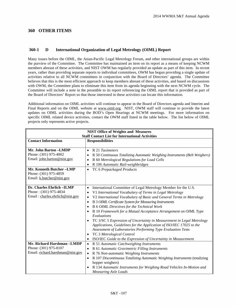
2014 WWMA S&T Annual Agenda
S&T –107
360 OTHER ITEMS
360-1 D International Organization of Legal Metrology (OIML) Report
Many issues before the OIML, the Asian-Pacific Legal Metrology Forum, and other international groups are within the purview of the Committee. The Committee has maintained an item on its report as a means of keeping NCWM members abreast of these activities, and NIST OWM has regularly provided an update as part of this item. In recent years, rather than providing separate reports to individual committees, OWM has begun providing a single update of activities relative to all NCWM committees in conjunction with the Board of Directors’ agenda. The Committee believes that this is the most efficient approach to keep members abreast of these activities, and based on discussions with OWM, the Committee plans to eliminate this item from its agenda beginning with the next NCWM cycle. The Committee will include a note in the preamble to its report referencing the OIML report that is provided as part of the Board of Directors’ Report so that those interested in these activities can locate this information.
Additional information on OIML activities will continue to appear in the Board of Directors agenda and Interim and Final Reports and on the OIML website at www.oiml.org. NIST, OWM staff will continue to provide the latest updates on OIML activities during the BOD’s Open Hearings at NCWM meetings. For more information on specific OIML related device activities, contact the OWM staff listed in the table below. The list below of OIML projects only represents active projects.
NIST Office of Weights and Measures Staff Contact List for International Activities
Contact Information Responsibilities
Mr. John Barton –LMDP Phone: (301) 975-4002 Email: [email protected]
• R 21 Taximeters • R 50 Continuous Totalizing Automatic Weighing Instruments (Belt Weighers) • R 60 Metrological Regulations for Load Cells • R 106 Automatic Rail-weighbridges
Mr. Kenneth Butcher –LMP Phone: (301) 975-4859 Email: [email protected]
• TC 6 Prepackaged Products
Dr. Charles Ehrlich –ILMP Phone : (301) 975-4834 Email : [email protected]
• International Committee of Legal Metrology Member for the U.S. • V1 International Vocabulary of Terms in Legal Metrology • V2 International Vocabulary of Basic and General Terms in Metrology • B 3 OIML Certificate System for Measuring Instruments • B 6 OIML Directives for the Technical Work • B 10 Framework for a Mutual Acceptance Arrangement on OIML Type
Evaluations • TC 3/SC 5 Expression of Uncertainty in Measurement in Legal Metrology
Applications, Guidelines for the Application of ISO/IEC 17025 to the Assessment of Laboratories Performing Type Evaluation Tests
• TC 3 Metrological Control • ISO/IEC Guide to the Expression of Uncertainty in Measurement
Mr. Richard Harshman –LMDP Phone: (301) 975-8107 Email: [email protected]
• R 51 Automatic Catchweighing Instruments • R 61 Automatic Gravimetric Filling Instruments • R 76 Non-automatic Weighing Instruments • R 107 Discontinuous Totalizing Automatic Weighing Instruments (totalizing
hopper weighers) • R 134 Automatic Instruments for Weighing Road Vehicles In-Motion and
Measuring Axle Loads

2014 WWMA S&T Annual Agenda
S&T – 108
Ms. Diane Lee –LMDP Phone: (301) 975-4405 Email: [email protected]
• R 59 Moisture Meters for Cereal Grains and Oilseeds • R 92 Wood Moisture Meters – Verification Methods and Equipment • TC 17/SC 8 Protein Measuring Instruments for Cereal Grains and Oil
Seeds Mr. Ralph Richter –ILMP Phone: (301) 975-3997 Email: [email protected]
• D 11 General Requirements for Measuring Instruments – Environmental Conditions
• R 35 Material Measures of Length for General Use • R 49 Water Meters (Cold Potable Water and Hot Water Meters) • R 71 Fixed Storage Tanks • R 80 Road and Rail Tankers (static measurement) • R 85 Automatic Level Gauges for Measuring the Level of Liquid in Fixed
Storage Tanks • R 95 Ship’s Tanks • R 117 Measuring Systems for Liquids Other Than Water (all measuring
technologies) • R 118 Testing Procedures and Test Report Format for Pattern Examination
of Fuel Dispensers for Motor Vehicles • TC 3/SC 4 Verification Period of Utility Meters Using Sampling
Inspections • R 137 Gas Meters (all measuring technologies) • R 140 Measuring Systems for Gaseous Fuel (i.e., large pipelines) • ISO TC 30/SC 7 Water Meters
Dr. Ambler Thompson –ILMP Phone: (301) 975-2333 Email: [email protected]
• V1 International Vocabulary of Terms in Legal Metrology • D 16 Principles of Assurance of Metrological Control • D 19 Pattern Evaluation and Pattern Approval • D 20 Initial and Subsequent Verification of Measuring Instruments and
Processes • D 27 Initial Verification of Measuring Instruments Using the
Manufacturer’s Quality Management System • D 31 General Requirements for Software Controlled Measuring
Instruments • R 34 Accuracy Classes of Measuring Instruments • R 46 Active Electrical Energy Meters for Direct Connection of Class 2
Ms. Juana Williams –LMDP Phone: (301) 975-3989 Email: [email protected]
• R 81 Dynamic Measuring Devices and Systems for Cryogenic Liquids • R 139 Compressed Gaseous Fuels Measuring Systems for Vehicles
List of Acronyms B Basic Publication LMDP Legal Metrology Devices Program CIML International Committee of Legal Metrology P Project D Document R Recommendation ILMP International Legal Metrology Program SC Subcommittee LMP Laws and Metrics Program TC Technical Committee
Contact Point: See contacts listed in the table above for specific technical areas. Regional Associations Comments: WWMA thanks NIST for their work in the International arena and looks forward to future updates. FYI, the next OIML meeting will be in Vietnam, 2013. The WWMA recommended that the item remain as a Developing Item. SWMA did not receive comments on this item and recommended further development. The SWMA continues to support these issues.

2014 WWMA S&T Annual Agenda
S&T –109
Item 360-1
Summary of comments considered by the regional committee (in writing or during the open hearings): No comments were heard during the open hearing. Item as proposed by the regional committee: (If different than agenda item) Committee recommendation to the region:
Voting Item on the NCWM Agenda Information Item on the NCWM Agenda Withdraw the Item from the NCWM Agenda (In the case of new items, do not forward to NCWM) Developing Item on the NCWM Agenda (To be developed by source)
Reasons for the committee recommendation: The WWMA S&T Committee supports the continuing effort of NIST OWM in regard to international activities.
COMPLETE SECTION BELOW FOLLOWING VOTING SESSION
Final updated or revised proposal from the region: (If different than regional committee recommendation) Regional recommendation to NCWM for item status:
Voting Item on the NCWM Agenda Information Item on the NCWM Agenda Withdraw the Item from the NCWM Agenda (In the case of new items, do not forward to NCWM) Developing Item on the NCWM Agenda (To be developed by source) Unable to consider at this time (Provide explanation in the “Additional Comments” section below)
Regional Report to NCWM: Please provide your report in this section exactly how you want it to appear in the NCWM reports to represent your region’s considerations, support or opposition, and recommendations. This will replace any previous reports from your region on this item. The WWMA supports the continuing effort of NIST OWM in regard to international activities and looks forward to further development in this area. Additional letters, presentations, and data may have been part of the Committee’s consideration. Please refer to http://ncwm.net/meetings/annual/publication-16 to review these documents.
360-2 This item was not submitted to your region (NEW)
360-3 Appendix D – Definitions: calibration parameter and multi-point calibrated device (NEW)
Source: NCWM Multi-Point Calibration Group (MPCG)
Purpose: Update the definitions in Appendix D to reflect advances in device calibration technology. Item Under Consideration: Amend NIST Handbook 44 Appendix D – Definitions as follows:
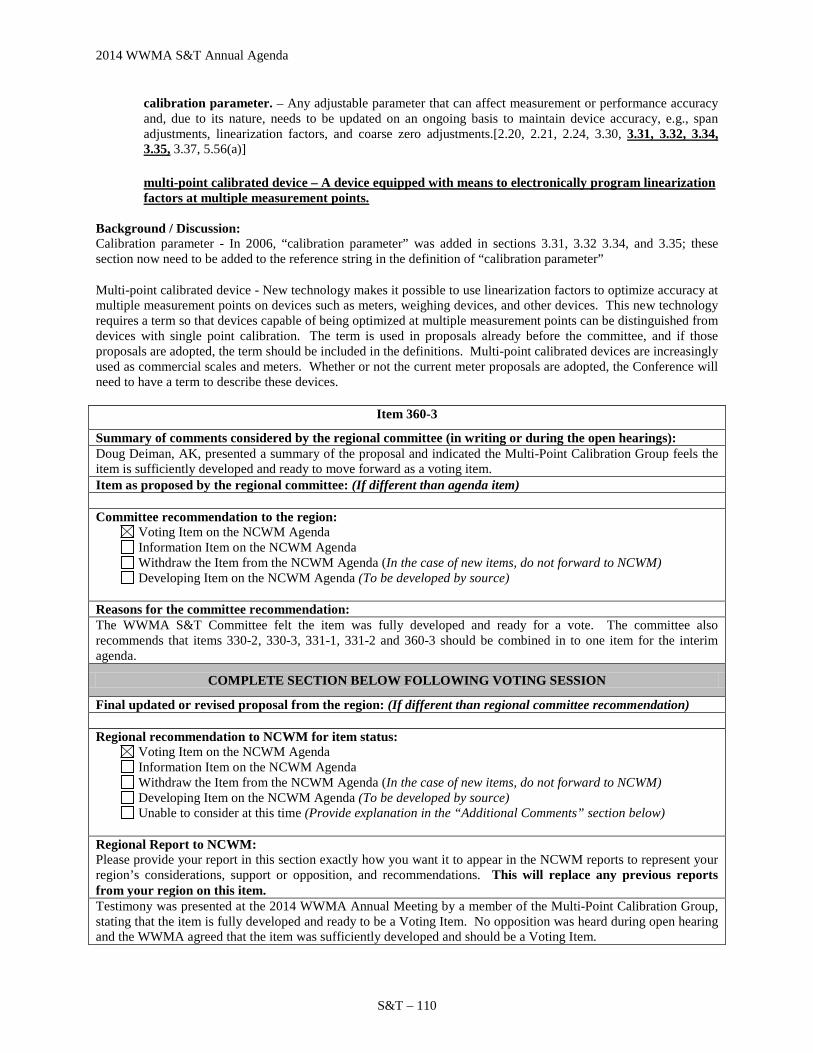
2014 WWMA S&T Annual Agenda
S&T – 110
calibration parameter. – Any adjustable parameter that can affect measurement or performance accuracy and, due to its nature, needs to be updated on an ongoing basis to maintain device accuracy, e.g., span adjustments, linearization factors, and coarse zero adjustments.[2.20, 2.21, 2.24, 3.30, 3.31, 3.32, 3.34, 3.35, 3.37, 5.56(a)] multi-point calibrated device – A device equipped with means to electronically program linearization factors at multiple measurement points.
Background / Discussion: Calibration parameter - In 2006, “calibration parameter” was added in sections 3.31, 3.32 3.34, and 3.35; these section now need to be added to the reference string in the definition of “calibration parameter”
Multi-point calibrated device - New technology makes it possible to use linearization factors to optimize accuracy at multiple measurement points on devices such as meters, weighing devices, and other devices. This new technology requires a term so that devices capable of being optimized at multiple measurement points can be distinguished from devices with single point calibration. The term is used in proposals already before the committee, and if those proposals are adopted, the term should be included in the definitions. Multi-point calibrated devices are increasingly used as commercial scales and meters. Whether or not the current meter proposals are adopted, the Conference will need to have a term to describe these devices.
Item 360-3
Summary of comments considered by the regional committee (in writing or during the open hearings): Doug Deiman, AK, presented a summary of the proposal and indicated the Multi-Point Calibration Group feels the item is sufficiently developed and ready to move forward as a voting item. Item as proposed by the regional committee: (If different than agenda item) Committee recommendation to the region:
Voting Item on the NCWM Agenda Information Item on the NCWM Agenda Withdraw the Item from the NCWM Agenda (In the case of new items, do not forward to NCWM) Developing Item on the NCWM Agenda (To be developed by source)
Reasons for the committee recommendation: The WWMA S&T Committee felt the item was fully developed and ready for a vote. The committee also recommends that items 330-2, 330-3, 331-1, 331-2 and 360-3 should be combined in to one item for the interim agenda.
COMPLETE SECTION BELOW FOLLOWING VOTING SESSION
Final updated or revised proposal from the region: (If different than regional committee recommendation) Regional recommendation to NCWM for item status:
Voting Item on the NCWM Agenda Information Item on the NCWM Agenda Withdraw the Item from the NCWM Agenda (In the case of new items, do not forward to NCWM) Developing Item on the NCWM Agenda (To be developed by source) Unable to consider at this time (Provide explanation in the “Additional Comments” section below)
Regional Report to NCWM: Please provide your report in this section exactly how you want it to appear in the NCWM reports to represent your region’s considerations, support or opposition, and recommendations. This will replace any previous reports from your region on this item. Testimony was presented at the 2014 WWMA Annual Meeting by a member of the Multi-Point Calibration Group, stating that the item is fully developed and ready to be a Voting Item. No opposition was heard during open hearing and the WWMA agreed that the item was sufficiently developed and should be a Voting Item.

2014 WWMA S&T Annual Agenda
S&T –111
360-4 Appendix D – Definitions. point-if-sale-system. (NEW)
Source: NIST USNWG on Taximeters
Purpose: Clarify the term “point-of-sale system” by providing a more detailed definition in Handbook 44, Appendix D.
Item Under Consideration: Amend NIST Handbook 44 Appendix D – Definitions as follows:
point-of-sale system. – An assembly of interactive elements including a weighing or measuring element, an indicating element, and a recording element (and may also be equipped with a “scanner”) used to complete a direct sales transaction. The system components, when operated together must be capable of the following: 1. determining the weight or measure of a product or service offered; 2. calculating a charge for the product or service based on the weight or measure and an
established price/rate structure; 3. determining a total cost that includes all associated charges involved with the transaction; 4 providing a sales receipt. (Amended 201X)
Background / Discussion: Stand-alone type of devices are becoming less prevalent in weighing and measuring applications and are evolving into more sophisticated weighing and measuring systems. Many different types of devices are now being connected to other components to create systems that are capable of performing all functions required to conduct a complete transaction.
While this proposed amendment does not remove any of the elements listed as required components in the existing definition for a POS, the USNWG on Taximeters agreed that the use of the wording “and may also be equipped with a scanner” in the existing definition is archaic, unnecessary and a specific reference to small capacity weighing systems and therefore, should be removed.
The USNWG on Taximeters could not agree upon the terms of classifying various assortments of components as point-of-sale systems (POS) when they are installed in taxis due to the type of components that comprise those systems when compared to the current definition of POS. The difficulty was largely due to the existing definition’s description of a POS as being a collection of specific pieces of hardware rather than placing more emphasis on what functions are performed when the system’s components operate as a system.
The current Handbook 44 Taximeters Code provides an option for, but does not require that a taximeter be capable of issuing a printed receipt. Because of this, some taximeter systems (that do not include a recording element) would not meet the existing definition of a POS. A taximeter may however, be connected to a sophisticated indicating element referred to as a passenger information monitor (PIM) located in the passenger’s area that can be capable of displaying an itemized account of the transaction and may also provide a means to complete the transaction via integral credit card reader. Even though this arrangement did not include a recording element, it was considered by some of the USNWG to constitute a POS. According to the definition, the taximeter and indicating element with a credit card reader as described above would not be considered to be a POS. This proposal would clarify that only when a system of interconnected components is capable of performing all of the functions listed in the amended definition, is it appropriate for that system to be defined as a POS.
The work group agreed that a POS should be capable of performing at a minimum, the four basic functions listed in the proposal. Rather than describing the hardware components of a POS, the USNWG’s proposed method of defining the POS was considered to be more generic and more readily applied to all types of weighing and measuring systems irrespective of the various components that are included within the system.
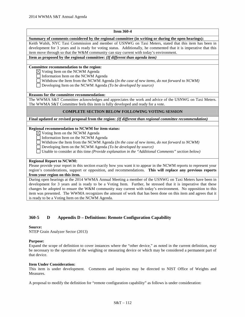
2014 WWMA S&T Annual Agenda
S&T – 112
Item 360-4
Summary of comments considered by the regional committee (in writing or during the open hearings): Keith Walsh, NYC Taxi Commission and member of USNWG on Taxi Meters, stated that this item has been in development for 3 years and is ready for voting status. Additionally, he commented that it is imperative that this item move through so that the W&M community can stay current with today’s environment. Item as proposed by the regional committee: (If different than agenda item) Committee recommendation to the region:
Voting Item on the NCWM Agenda Information Item on the NCWM Agenda Withdraw the Item from the NCWM Agenda (In the case of new items, do not forward to NCWM) Developing Item on the NCWM Agenda (To be developed by source)
Reasons for the committee recommendation: The WWMA S&T Committee acknowledges and appreciates the work and advice of the USNWG on Taxi Meters. The WWMA S&T Committee feels this item is fully developed and ready for a vote.
COMPLETE SECTION BELOW FOLLOWING VOTING SESSION
Final updated or revised proposal from the region: (If different than regional committee recommendation) Regional recommendation to NCWM for item status:
Voting Item on the NCWM Agenda Information Item on the NCWM Agenda Withdraw the Item from the NCWM Agenda (In the case of new items, do not forward to NCWM) Developing Item on the NCWM Agenda (To be developed by source) Unable to consider at this time (Provide explanation in the “Additional Comments” section below)
Regional Report to NCWM: Please provide your report in this section exactly how you want it to appear in the NCWM reports to represent your region’s considerations, support or opposition, and recommendations. This will replace any previous reports from your region on this item. During open hearings at the 2014 WWMA Annual Meeting a member of the USNWG on Taxi Meters have been in development for 3 years and is ready to be a Voting Item. Further, he stressed that it is imperative that these changes be adopted to ensure the W&M community stay current with today’s environment. No opposition to this item was presented. The WWMA recognizes the amount of work that has been done on this item and agrees that it is ready to be a Voting Item on the NCWM Agenda.
360-5 D Appendix D – Definitions: Remote Configuration Capability
Source: NTEP Grain Analyzer Sector (2013)
Purpose: Expand the scope of definition to cover instances where the “other device,” as noted in the current definition, may be necessary to the operation of the weighing or measuring device or which may be considered a permanent part of that device.
Item Under Consideration: This item is under development. Comments and inquiries may be directed to NIST Office of Weights and Measures.
A proposal to modify the definition for “remote configuration capability” as follows is under consideration:

2014 WWMA S&T Annual Agenda
S&T –113
remote configuration capability. – The ability to adjust a weighing or measuring device or change its sealable parameters from or through some other device that is not may or may not itself be necessary to the operation of the weighing or measuring device or is not may or may not be a permanent part of that device.[2.20, 2.21, 2.24, 3.30, 3.37, 5.56(a)] (Added 1993, Amended 20XX)
Background / Discussion: Removable digital storage devices can be used in GMMs as either data transfer devices that are not necessary to the operation of the GMM or as data storage devices which are necessary to the operation of the GMM. If removable data storage devices are necessary to the operation of the device, they are not covered by the current definition of remote configuration capability.
A USB flash drive is most likely to be used as a data transfer device. In a typical data transfer application, the USB flash drive is first connected to a computer with access to the GMM manufacturer’s web site to download the latest grain calibrations that are then stored in the USB flash drive. The USB flash drive is removed from the computer and plugged into a USB port on the GMM. The GMM is put into remote configuration mode to copy the new grain calibration data into the GMM’s internal memory. When the GMM has been returned to normal operating (measuring) mode the USB flash drive can be removed from the GMM.
Although a Secure Digital (SD) memory card could also be used as a data transfer device it is more likely to be used as a data storage device. In a typical “data storage device” application, the SD memory card stores the grain calibrations used on the GMM. The SD memory card must be plugged into an SD memory card connector on a GMM circuit card for the GMM to operate in measuring mode. To install new grain calibrations the GMM must be turned “off” or put into a mode in which the SD memory card can be safely removed. The SD memory card can either be replaced with an SD memory card that has been programmed with the new grain calibrations or the original SD memory card can be re-programmed with the new grain calibrations in much the same way as that described in the preceding paragraph to copy new grain calibrations into a USB flash drive. In either case, the SD memory card containing the new calibrations must be installed in the GMM for the GMM to operate in measuring mode. In that regard, the SD memory card (although removable) can be considered a permanent part of the GMM in that the GMM cannot operate without it. Note: In the above example SD memory card could be any removable flash memory card such as the Secure Digital Standard-Capacity, the Secure Digital High-Capacity, the Secure Digital Extended-Capacity, and the Secure Digital Input/Output, which combines input/output functions with data storage. These come in three form factors: the original size, the mini size, and the micro size. A Memory Stick is a removable flash memory card format, launched by Sony in 1998, and is also used in general to describe the whole family of Memory Sticks. In addition to the original Memory Stick, this family includes the Memory Stick PRO, the Memory Stick Duo, the Memory Stick PRO Duo, the Memory Stick Micro, and the Memory Stick PRO-HG. At its 2011 Grain Analyzer Sector Meeting the Sector agreed by consensus that the following changes to Table S.2.5. of §5.56.(a) of NIST Handbook 44 should be forwarded to the S&T Committee for consideration:
• Add a note to Table S.2.5. to recognize the expanded scope of remote capability. • Delete “remotely” from the second paragraph of Category 3 requirements that begins, “When accessed
remotely …” to make it clear that the requirements of Category 3 apply whether accessed manually using the keyboard or accessed by remote means.
• Add the modified second paragraph of Category 3 requirements to Categories 3a and 3b to make it clear that these requirements apply to all the subcategories of Category 3.
Because a change to the definition of remote configuration capability will apply to other device types, NIST OWM recommended that the changes to Table S.2.5. approved by the Sector in 2011 be separated into two independent proposals. One proposal would deal with the changes to Category 3 and its subcategories. The second would recommend a modification of the definition of “remote configuration capability” appearing in Appendix D of NIST

2014 WWMA S&T Annual Agenda
S&T – 114
Handbook 44 to recognize the expanded scope of remote capability; this proposal would be an alternative to adding a note to the bottom of Table S.2.5. to expand the definition for remote configuration for grain moisture meters (as shown in this proposal). At its 2012 Meeting, the Grain Analyzer Sector agreed to separate its original proposal into two separate proposals and agreed to forward this proposal to change the definition of “remote configuration capability” to the S&T to Committee for consideration. See also August 2012 NTEP Grain Analyzer Sector Summary, Item 5. During its Open Hearings at the 2013 NCWM Interim Meeting, the Committee heard comments from Ms. Juana Williams (NIST OWM). OWM suggested the Committee consider this item as a Developing Item to allow other NTEP sectors to discuss how a change to the definition may affect other device types of similar design and to consider changes, if needed. OWM recognizes that the current definition for “remote configuration capability” may not address those grain moisture meters (GMMs) which can only be operated with a removable data storage device, containing, among other things, the grain calibrations intended for use with the GMM, inserted in the device (as was described by the Grain Analyzer Sector). As such, OWM noted that current sealing requirements were developed at a time when such technology likely didn’t exist, nor could be envisioned, and are based on the current definition of remote configuration capability. Because the current definition was never intended to apply to this “next generation” technology, OWM suggested that those charged with further development of this item may wish to revisit the five philosophies of sealing and consider whether a new paragraph, completely separate from current sealing requirements, might be appropriate and a better option, than the one currently proposed. The five philosophies of sealing are included in the 1992 Report of the 77th National Conference on Weights and Measures (Report of the Specifications and Tolerances Committee). Another option, preferred over the changes currently proposed, would be to add a separate statement to the current definition of “remote configuration capability” to address removable storage devices. For example, the following sentence might be considered as an addition to the current definition for “remote configuration capability:”
Devices which are programmed using removable media (such as SD cards, flash drives, etc.) that may or may not be required to remain with the device during normal operation are also considered to be remotely configured devices.
The Committee also heard comments from Mr. Dmitri Karimov (Liquid Controls Corporation, LLC), speaking on behalf of the MMA, who made two points: (1) Flow computers may already have these capabilities, thus, it may be more appropriate to consider adding requirements to the General Code so that the requirements will be uniformly applied to all device types; and (2) the Committee should look ahead and consider other capabilities, such as wireless communication and configuration, that may already have emerged. The Committee acknowledged the comments indicating that the current definition of “remote configuration capability” was developed at a time when certain technologies, such as blue tooth, SD storage devices, flash drives, and other media didn’t exist. The Committee recognized that it may be difficult to modify the existing definition and associated requirements to be flexible enough to address emerging and future technologies without having a significant (and possibly detrimental impact) on existing devices. Consequently, rather than modifying the current definition, the Committee concluded that a better approach might be to develop an entirely separate set of security requirements that would apply to emerging technologies. The Committee believes that additional work is needed to develop proposed definition(s) and associated requirements and decided to designate the item as Developmental. The Committee requests other sectors review the Grain Sector’s proposed modification to the definition as well as OWM’s suggestions and provide input. On the 2013 NCWM Online Position Forum, one Government representative indicated a neutral position on this item with no additional comments. At the 2013 NCWM Annual Meeting Open Hearings, the Committee heard comments from Juana Williams (NIST OWM) who reiterated OWM’s comments from the 2013 Interim Meeting, suggesting that it may be appropriate to develop separate requirements to address new and future technologies which can be remotely configured with removable media. OWM plans to develop draft language and ask for input from the various sectors at their upcoming meetings. Ms. Williams also noted the suggestion made at the 2013 NCWM Interim Meeting by
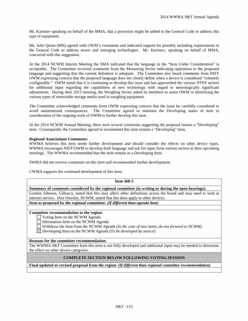
2014 WWMA S&T Annual Agenda
S&T –115
Mr. Karimov speaking on behalf of the MMA, that a provision might be added to the General Code to address this type of equipment. Ms. Julie Quinn (MN) agreed with OWM’s comments and indicated support for possibly including requirements in the General Code to address newer and emerging technologies. Mr. Karimov, speaking on behalf of MMA, concurred with this suggestion. At the 2014 NCWM Interim Meeting the SMA indicated that the language in the “Item Under Consideration” is acceptable. The Committee received comments from the Measuring Sector indicating opposition to the proposed language and suggesting that the current definition is adequate. The Committee also heard comments from NIST OWM expressing concern that the proposed language does not clearly define when a device is considered “remotely configurable.” OWM noted that it is continuing to develop this issue and has approached the various NTEP sectors for additional input regarding the capabilities of new technology with regard to metrologically significant adjustments. During their 2013 meeting, the Weighing Sector asked its members to assist OWM in identifying the various types of removable storage media used in weighing equipment. The Committee acknowledged comments from OWM expressing concern that the issue be carefully considered to avoid unintentional consequences. The Committee agreed to maintain the Developing status of item in consideration of the ongoing work of OWM to further develop this item. At the 2014 NCWM Annual Meeting, there were several comments suggesting the proposal remain a “Developing” item. Consequently the Committee agreed to recommend this item remain a “Developing” item.
Regional Associations Comments: WWMA believes this item needs further development and should consider the effects on other device types. WWMA encourages NIST/OWM to develop draft language and ask for input from various sectors at their upcoming meetings. The WWMA recommended that the item remain as a Developing Item. SWMA did not receive comments on this item and recommended further development. CWMA supports the continued development of this item.
Item 360-5
Summary of comments considered by the regional committee (in writing or during the open hearings): Gordon Johnson, Gilbarco, stated that this may affect other definitions across the board and may need to look at internet service. Don Onwiler, NCWM, stated that this does apply to other devices. Item as proposed by the regional committee: (If different than agenda item) Committee recommendation to the region:
Voting Item on the NCWM Agenda Information Item on the NCWM Agenda Withdraw the Item from the NCWM Agenda (In the case of new items, do not forward to NCWM) Developing Item on the NCWM Agenda (To be developed by source)
Reasons for the committee recommendation: The WWMA S&T Committee feels this item is not fully developed and additional input may be needed to determine the effect on other device categories.
COMPLETE SECTION BELOW FOLLOWING VOTING SESSION
Final updated or revised proposal from the region: (If different than regional committee recommendation)

2014 WWMA S&T Annual Agenda
S&T – 116
Regional recommendation to NCWM for item status: Voting Item on the NCWM Agenda Information Item on the NCWM Agenda Withdraw the Item from the NCWM Agenda (In the case of new items, do not forward to NCWM) Developing Item on the NCWM Agenda (To be developed by source) Unable to consider at this time (Provide explanation in the “Additional Comments” section below)
Regional Report to NCWM: Please provide your report in this section exactly how you want it to appear in the NCWM reports to represent your region’s considerations, support or opposition, and recommendations. This will replace any previous reports from your region on this item. During open hearing at the 2014 WWMA Annual Meeting and industry representative questioned whether or not this item would affect definitions for other device types. An NCWM representative expressed the opinion that it does affect other devices. The WWMA supports this as a Developing Item to allow additional input and consideration. Additional letters, presentations, and data may have been part of the Committee’s consideration. Please refer to http://ncwm.net/meetings/annual/publication-16 to review these documents.
360-6 D Electric Vehicle Fueling and Submetering
Source: California Department of Food and Agriculture Division of Measurement Standards (2014) Purpose: Keep the weights and measures community apprised of work to develop standards for Electric Vehicle Fueling and Submetering (EVF&S) and to encourage their participation in this work. Item Under Consideration: The USNWG for Electric Vehicle Fueling and Submetering is developing proposed specifications, tolerances, and other technical requirements for Electric Vehicle Fueling and Submetering Systems for inclusion in NIST Handbook 44. The code currently under development by the USNWG is included in Appendix H; however, this draft is NOT yet ready for consideration by the NCWM. The USNWG plans to complete revisions to this document and submit a final draft version to the regional weights and measures associations by Fall 2014. Background / Discussion: In 2013, the NCWM adopted a uniform method of sale for retail electrical energy sold as a vehicle fuel. Adding specifications, tolerances, and other technical requirements for equipment that measures electricity as a motor fuel are necessary to provide consumer confidence that measurement of electricity is accurate and that there is sufficient information for the selection of charging equipment, (Levels I, II, and III), and price to pay. The U.S. National Work Group on Measuring Systems for Electric Vehicle Fueling and Submetering (USNWG EVF&S) discussed a number of challenges to field inspection and testing of EVSE systems. Utility companies and at least one U.S. Weights and Measures jurisdiction have established test procedures and test equipment specifications for utility-type and submetering electrical energy metering applications. The USNWG EVF&S was formed to develop proposed requirements for commercial electricity-measuring devices (including those used to measure and sell electricity commercially delivered as vehicle fuel and those used in submetering electricity at residential and business locations) and to ensure that the prescribed methodologies and standards facilitate measurements that are traceable to the International System of Units (SI). The “West Coast Electric Highway” is a project with an extensive network of electric vehicle DC fast charging stations located every 25 to 50 miles along Interstate 5 and other major roadways in the Pacific Northwest. In

2014 WWMA S&T Annual Agenda
S&T –117
California alone, there are currently 1,387 electric charging stations and over one million plug-in electric vehicles (PEV) are projected to be on California roads by 2020. The development of standards for PEV charging equipment is needed to provide consumers with fueling experiences and expectations similar to those at traditional gasoline dispensers. Additionally, these standards, once they are developed and adopted, will be used to provide training and education to weights and measures officials about testing and regulating these devices, and support uniform standards and enforcement of these standards throughout the United States. See Appendix H for a Tentative Code being considered by the USNWG EVF&S. At the 2014 NCWM Interim Meeting Ms. Juana Williams (NIST OWM), Technical Advisor to the USNWG EVF&S reported that the USWNG met two weeks prior to the Interim Meeting and is continuing work on a draft code for eventual inclusion in NIST Handbook 44. Ms. Williams emphasized that because the USWNG has additional work to complete on various portions of the draft Code, the draft is not ready for consideration by the NCWM. The draft included in NCWM Publication 15 has been revised and will be made available on the NIST OWM Web Page. The USNWG will hold several meetings over the next six months and plans to submit a final draft in Fall 2014. Mrs. Tina Butcher (NIST OWM), Chairman of the USNWG, asked that state and local jurisdictions provide contact information of appropriate personnel from their corresponding public utility to assist the Work Group in identifying specific requirements that apply to EVSE in their jurisdictions. The Committee acknowledged the need for EVSE Industry to participate in the NCWM process. This need was also expressed through comments heard during the open hearings. The Committee heard additional comments from a member of the Work Group who noted that a limited number of weights and measures officials are members of the Work Group and encouraged more to participate. The Committee agreed forward to further work by the USNWG and agreed to designate this as a Developing item. At the 2014 NCWM Annual Meeting, Ms. Tina Butcher (NIST), Chairman of the USNWG, reported on the progress of the WG and noted that the WG plans to submit a proposal for regional consideration in the fall with a request that it be designated as a “Voting” item at that time. Mr. Ted Bohn, Argonne National Laboratory reported on the progress of the EVSE subcommittee and displayed a sample of a prototype test unit. The Committee heard comments in support of the item. The Committee looks forward to seeing the proposal from the Work Group and recommends that this item remain a “Developing” item until such time that the draft is submitted. Regional Associations Comments: The WWMA recognized that the draft tentative Code is still under development by the USNWG. The WWMA recommends all jurisdictions review the draft tentative Code and provide comments to the WG. The WWMA recommended that the item remain as a Developing Item. SWMA did not receive any comments. The SWMA recommends the item remain as a Developing Item. The SWMA forwarded the item to NCWM. CWMA supports the continued development of this item.
Item 360-6
Summary of comments considered by the regional committee (in writing or during the open hearings): Kristin Macey, CA, John Young, Yolo County, Steve Cook, CA, Paul Jordan, Ventura County and Ron Hasemeyer, Alameda County all stated that this item is fully developed and voiced support for moving this item to voting status. The revised proposal was submitted by the USNWG on Electric Vehicle Fueling and Submetering prior to open hearings. Item as proposed by the regional committee: (If different than agenda item) Due to the size of the revised proposal it was unable to be attached to this addendum. It will be attached to the S&T

2014 WWMA S&T Annual Agenda
S&T – 118
Committee Report upon submittal to the NCWM. Committee recommendation to the region:
Voting Item on the NCWM Agenda Information Item on the NCWM Agenda Withdraw the Item from the NCWM Agenda (In the case of new items, do not forward to NCWM) Developing Item on the NCWM Agenda (To be developed by source)
Reasons for the committee recommendation: The WWMA S&T Committee acknowledges and appreciates the amount of work that has been done by the USNWG EVF&S in developing this item. We feel that it is fully developed and ready to move to voting status as a Tentative Code.
COMPLETE SECTION BELOW FOLLOWING VOTING SESSION
Final updated or revised proposal from the region: (If different than regional committee recommendation) Regional recommendation to NCWM for item status:
Voting Item on the NCWM Agenda Information Item on the NCWM Agenda Withdraw the Item from the NCWM Agenda (In the case of new items, do not forward to NCWM) Developing Item on the NCWM Agenda (To be developed by source) Unable to consider at this time (Provide explanation in the “Additional Comments” section below)
Regional Report to NCWM: Please provide your report in this section exactly how you want it to appear in the NCWM reports to represent your region’s considerations, support or opposition, and recommendations. This will replace any previous reports from your region on this item. During open hearing of the 2014 WWMA Annual Meeting several regulators voiced support of this item and stated that it is fully developed and should be a Voting Item. The WWMA agrees with this opinion and appreciates the amount of work completed that has been completed. Due to the size of the revision the tentative code will be attached to the 2014 WWMA S&T Committee Annual Report as Appendix A and changes to the Timing Device Code at Appendix B. Additional letters, presentations, and data may have been part of the Committee’s consideration. Please refer to http://ncwm.net/meetings/annual/publication-16 to review these documents.
Mr. Bob Weidler, Wyoming | Committee Chair Mr. Laurence Nolan, Los Angeles County, California | Member Mr. Ronald Hasemeyer, Alameda County, California | Member Mr. Nathan Gardner, Oregon | Member Mr. Wayne Reinert, Colorado | Member Mr. Brett Gurney, Utah | Ex-Officio Mr. Clark Cooney, NIST OWM | Technical Advisor Specifications and Tolerances Committee

2014 WWMA S&T Annual Agenda Appendix A
S&T –A 1
Appendix A
Item 320-3 Draft Tentative Code Applicable to Weigh-In-Motion Systems Used for Vehicle Enforcement Screening
Section 2.25. Weigh-In-Motion Systems used for Vehicle Enforcement Screening – Draft Code
A. Application
A.1. General. – This code applies to systems used to weigh vehicles, while in motion, for the purpose of screening and sorting the vehicles based on the vehicle weight to determine if a static weighment is necessary. A.2. The code does not apply to weighing systems intended for the collection of statistical traffic data. A.3. The code is intended for field enforcement use only. A.4. Additional Code Requirements. – In addition to the requirements of this code, Weigh-In-Motion Screening Systems shall meet the requirements of Section 1.10. General Code.
S. Specifications
S.1. Design of Indicating and Recording Elements and of Recorded Representations. S.1.1. Ready Indication. – The system shall provide a means of verifying that the system is operational and ready for use.
S.1.2. Value of System Division Units. – The value of a system division “d” expressed in a unit of weight shall be equal to:
(a) 1, 2, or 5; or
(b) a decimal multiple or submultiple of 1, 2, or 5. Examples: divisions may be 10, 20, 50, 100; or 0.01, 0.02, 0.05; or 0.1, 0.2, 0.5, etc.
S.1.2.1. Units of Measure. – The system shall indicate weight values using only a single unit of measure.
S.1.3. Value of Other Units of Measure.

2014 WWMA S&T Annual Agenda Appendix A
S&T – A 2
S.1.3.1. Speed. – Vehicle speeds shall be measured in miles per hour or kilometers per hour. S.1.3.2. Axle-Spacing (Length). – The center-to-center distance between any two successive axles shall be measured in feet and/or inches, or meters. S.1.3.3. Vehicle Length. – If the system is capable of measuring the overall length of the vehicle, the length of the vehicle shall be measured in feet and/or inches, or meters.
S.1.4. Capacity Indication. – An indicating or recording element shall not display nor record any values greater than 105% of the specified capacity of the load receiving element.
S.1.5. Identification of a Fault. – Fault conditions shall be presented to the operator in a clear and unambiguous means. The following fault conditions shall be identified:
(a) Vehicle speed is below the minimum or above the maximum speed as specified. (b) The maximum number of vehicle axles as specified has been exceeded. (c) A change in vehicle speed greater than that specified has been detected.
S.1.6. Recorded Representations.
S.1.6.1. Values to be Recorded. – At a minimum, the following values shall be printed and/or stored electronically for each vehicle weighment:
(a) transaction identification number (b) lane identification (required if more than one lane at the site has the ability to
weigh a vehicle in-motion) (c) vehicle speed (d) number of axles (e) weight of each axle (f) identification and weight of axles groups (g) axle spacing (h) total vehicle weight (i) all fault conditions that occurred during the weighing of the vehicle (j) violations, as identified in paragraph S.2.1., that occurred during the weighing of
the vehicle. (k) time & date
S.1.7. Value of the Indicated and Recorded System Division. – The value of the system’s division size as recorded shall be the same as the division value indicated.
S.2. System Design Requirements.
S.2.1. Violation Parameters. – The instrument shall be capable of accepting user entered violation parameters for the following items:
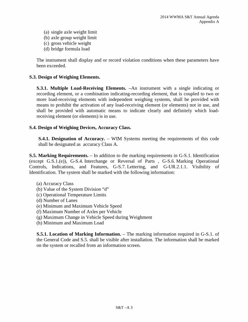
2014 WWMA S&T Annual Agenda Appendix A
S&T –A 3
(a) single axle weight limit (b) axle group weight limit (c) gross vehicle weight (d) bridge formula load
The instrument shall display and or record violation conditions when these parameters have been exceeded.
S.3. Design of Weighing Elements.
S.3.1. Multiple Load-Receiving Elements. –An instrument with a single indicating or recording element, or a combination indicating-recording element, that is coupled to two or more load-receiving elements with independent weighing systems, shall be provided with means to prohibit the activation of any load-receiving element (or elements) not in use, and shall be provided with automatic means to indicate clearly and definitely which load-receiving element (or elements) is in use.
S.4. Design of Weighing Devices, Accuracy Class.
S.4.1. Designation of Accuracy. – WIM Systems meeting the requirements of this code shall be designated as accuracy Class A.
S.5. Marking Requirements. – In addition to the marking requirements in G-S.1. Identification (except G.S.1.(e)), G-S.4. Interchange or Reversal of Parts , G-S.6. Marking Operational Controls, Indications, and Features, G-S.7. Lettering, and G-UR.2.1.1. Visibility of Identification. The system shall be marked with the following information:
(a) Accuracy Class (b) Value of the System Division “d” (c) Operational Temperature Limits (d) Number of Lanes (e) Minimum and Maximum Vehicle Speed (f) Maximum Number of Axles per Vehicle (g) Maximum Change in Vehicle Speed during Weighment (h) Minimum and Maximum Load
S.5.1. Location of Marking Information. – The marking information required in G-S.1. of the General Code and S.5. shall be visible after installation. The information shall be marked on the system or recalled from an information screen.

2014 WWMA S&T Annual Agenda Appendix A
S&T – A 4
N. Notes
N.1. Test Procedures.
N.1.1. Selection of Test Vehicles. – All dynamic testing associated with the procedures described in each of the subparagraphs of N.1.5 shall be performed with a minimum of two test vehicles.
(a) The first test vehicle may be a two axle, six tire, single unit truck; a vehicle with two axles with the rear axle having dual wheels. The vehicle shall have a maximum Gross Vehicle Weight of 10,000 lbs.
(b) The second test vehicle shall be a five axle, single trailer truck with a maximum Gross Vehicle Weight of 80,000 lbs.
Note: Consideration should be made for testing the systems using vehicles which are
typical to the systems daily operation.
N.1.1.1. Weighing of Test Vehicles. – All test vehicles shall be weighed on a reference scale before being used to conduct the dynamic tests.
N.1.2. Test Loads.
N.1.2.1. Static Test Loads. – All static test loads shall use certified test weights.
N.1.2.2. Dynamic Test Loads. – Test vehicles used for dynamic testing shall be loaded to 85 to 95% of their maximum Gross Vehicle Weight. The “load” shall be non-shifting and shall be positioned to present as close as possible, an equal side-to-side load.
N.1.3. Reference Scale. – Each reference vehicle shall be weighed on a static scale meeting NIST Handbook 44, Class III L maintenance tolerances.
N.1.3.1. Location of a Reference Scale. – The location of the Reference Scale must be considered as vehicle weights will change due to fuel consumption.
N.1.4. Test Speeds. – All dynamic tests shall be conducted within 20% below or at the posted speed limit. N.1.5. Test Procedures.
N.1.5.1. Dynamic Load Test. – The dynamic test shall be conducted using the test vehicles defined in N.1.1. The test shall consist of a minimum of 20 runs for each test vehicle at the speed as stated in N.1.4. The tolerance for each run shall be based on the percentage values specified in Table T.3.1.
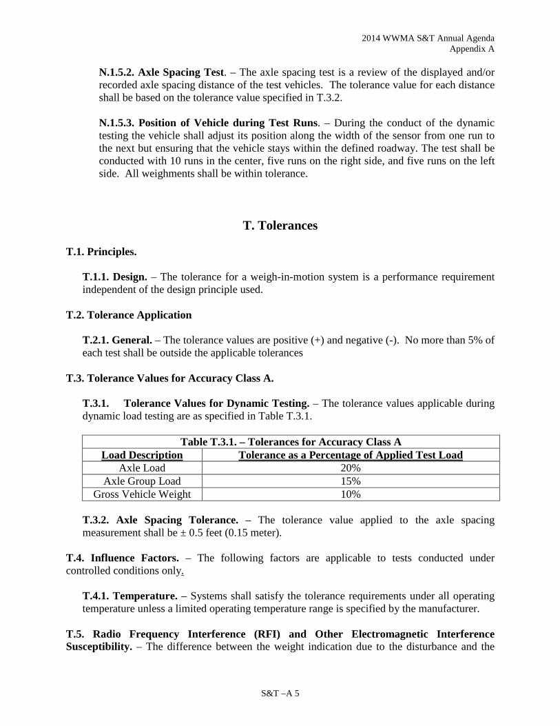
2014 WWMA S&T Annual Agenda Appendix A
S&T –A 5
N.1.5.2. Axle Spacing Test. – The axle spacing test is a review of the displayed and/or recorded axle spacing distance of the test vehicles. The tolerance value for each distance shall be based on the tolerance value specified in T.3.2.
N.1.5.3. Position of Vehicle during Test Runs. – During the conduct of the dynamic testing the vehicle shall adjust its position along the width of the sensor from one run to the next but ensuring that the vehicle stays within the defined roadway. The test shall be conducted with 10 runs in the center, five runs on the right side, and five runs on the left side. All weighments shall be within tolerance.
T. Tolerances
T.1. Principles.
T.1.1. Design. – The tolerance for a weigh-in-motion system is a performance requirement independent of the design principle used.
T.2. Tolerance Application
T.2.1. General. – The tolerance values are positive (+) and negative (-). No more than 5% of each test shall be outside the applicable tolerances
T.3. Tolerance Values for Accuracy Class A.
T.3.1. Tolerance Values for Dynamic Testing. – The tolerance values applicable during dynamic load testing are as specified in Table T.3.1.
Table T.3.1. – Tolerances for Accuracy Class A Load Description Tolerance as a Percentage of Applied Test Load
Axle Load 20% Axle Group Load 15%
Gross Vehicle Weight 10%
T.3.2. Axle Spacing Tolerance. – The tolerance value applied to the axle spacing measurement shall be ± 0.5 feet (0.15 meter).
T.4. Influence Factors. – The following factors are applicable to tests conducted under controlled conditions only.
T.4.1. Temperature. – Systems shall satisfy the tolerance requirements under all operating temperature unless a limited operating temperature range is specified by the manufacturer.
T.5. Radio Frequency Interference (RFI) and Other Electromagnetic Interference Susceptibility. – The difference between the weight indication due to the disturbance and the

2014 WWMA S&T Annual Agenda Appendix A
S&T – A 6
weight indication without the disturbance shall not exceed the tolerance value as stated in Table T.3.1.
UR. User Requirements
UR.1. Selection Requirements. – Equipment shall be suitable for the service in which it is used with respect to elements of its design, including but not limited to, its capacity, number of scale divisions, value of the scale division or verification scale division and minimum capacity. UR.2. User Location Conditions and Maintenance. – The system shall be installed and maintained as defined in the manufacturer’s recommendation.
UR.2.1. System Modification. – The dimensions (e.g., length, width, thickness, etc.) of the load receiving element of a system shall not be changed beyond the manufacturer’s specifications, nor shall the capacity of a scale be increased beyond its design capacity by replacing or modifying the original primary indicating or recording element with one of a higher capacity, except when the modification has been approved by a competent engineering authority, preferably that of the engineering department of the manufacturer of the system, and by the weights and measures authority having jurisdiction over the system. UR.2.2. Foundation, Supports, and Clearance. – The foundation and supports shall be such as to provide strength, rigidity, and permanence of all components. On load-receiving elements which use moving parts for determining the load value, clearance shall be provided around all live parts to the extent that no contacts may result when the load-receiving element is empty, nor throughout the weighing range of the system. UR.2.3. Access to Weighing Elements. – If necessary, adequate provision shall be made for inspection and maintenance of the weighing elements.
UR.3. Maximum Load. – A system shall not be used to weigh a load of more than the marked maximum load of the system.

2014 WWMA S&T Annual Agenda Appendix A
S&T –A 7
The following are proposed definitions to be added to NIST Handbook 44, Appendix D to support the Weigh-In-Motion Systems used for Vehicle Enforcement Screening – Draft Code. weigh-in-motion (WIM). A process of estimating a moving vehicle’s gross weight and the portion of that weight that is carried by each wheel, axle, or axle group, or combination thereof, by measurement and analysis of dynamic vehicle tire forces. axle. The axis oriented transversely to the nominal direction of vehicle motion, and extending the full width of the vehicle, about which the wheel(s) at both ends rotate. axle-group load. The sum of all tire loads of the wheels on a group of adjacent axles; a portion of the gross-vehicle weight. axle load. The sum of all tire loads of the wheels on an axle; a portion of the gross-vehicle weight. axle spacing. The distance between the centers of any two axles. When specifying axle spacing, you also need to identify the axles used.
single-axle load. The load transmitted to the road surface by the tires lying on the same longitudinal axis (that axis transverse to the movement of the vehicle and about which the wheels rotate). tandem-axle load. The load transmitted to the road surface by the tires of two single-axles lying on the same longitudinal axis (that axis transverse to the movement of the vehicle and about which the wheels rotate). triple-axle load. The load transmitted to the road surface by the tires of three single-axles lying on the same longitudinal axis (that axis transverse to the movement of the vehicle and about which the wheels rotate). Weigh-in-Motion Screening Scale . A WIM system used to identify potentially overweight vehicles. Wheel weight. The weight value of any single or set of wheels on one side of a vehicle on a single axle. WIM System. A set of sensors and supporting instruments that measure the presence of a moving vehicle and the related dynamic tire forces at specified locations with respect to time; estimate tire loads; calculate speed, axle spacing, vehicle class according to axle arrangement, and other parameters concerning the vehicle; and process, display, store, and transmit this information. This standard applies only to highway vehicles.

2014 WWMA S&T Annual Agenda Appendix A
S&T – A 8

2014 WWMA S&T Annual Agenda Appendix B
S&T –B 1
Appendix B
Item 330-1 N.4.2.5. Determination of Error on Whole Sale Devices with Multiple Flow Rates and Calibration Factors
How Slow Flow Accuracy Affects LMD’s Because the legal tolerance on slow flow tests is so great (+/-0.5%) compared to industry standards (typically +/- 0.05%), and because slow flow tests themselves are so time consuming, registered service agents may be tempted to skip slow flow tests entirely during seasonal re-calibrations. Even if one ignores the fact that the Liquid Measuring Device Code in NIST Handbook 44 requires that a special test be done at the slow flow rate, there remains a very good reason that slow flow rates should always be tested. If the error at the slow flow rate is unknown, then it is impossible to calibrate the high flow rates to deliver with the extreme accuracy sought by industry on quantities which are greater or less than the test prover used at the time of calibration.
Imagine a typical whole sale meter which is calibrated using a 1,000 gallon prover at a terminal where the customers’ trucks have pocket sizes between 1,000 and 4,000 gallons. The meter has an electronic register programmed with a slow flow rate for start-up and shut-down, a high-flow rate for typical deliveries, and a mid-speed fallback rate for when the pumps can’t keep up with demand. Startup and shutdown deliveries are 100 gallons each regardless of total quantity delivered.
Now imagine that the service agent calibrating the meter didn’t check the slow flow rate and didn’t know that the meter was short five gallons on a one thousand gallon test. Instead, he calibrated the fallback and normal flow rates without testing the slow flow and introduced a linear error which increases the farther the transaction quantity deviates from the prover size. On a 1,000 gallon delivery the meter would appear to be accurate, but on a 3,400 gallon delivery a three gallon error has been introduced. That is a 0.09% error which is almost twice the typical industry goal.
When calibrating at the normal and fallback speeds, the meter registers 200 gallons of product for the startup and shutdown, but actually delivers only 199 gallons. (99.5 gallons delivered for every 100 gallons registered at slow speed.) If the service technician calibrates the meter to zero at normal and fallback rates, the meter will actually deliver 801 gallons for every 800 gallons it registers at those rates.
Every subsequent delivery of 1000 gallons should receive exactly the right amount. Every delivery exceeding 1000 gallons will be ‘long’ and every delivery less than 1000 gallons will be short.
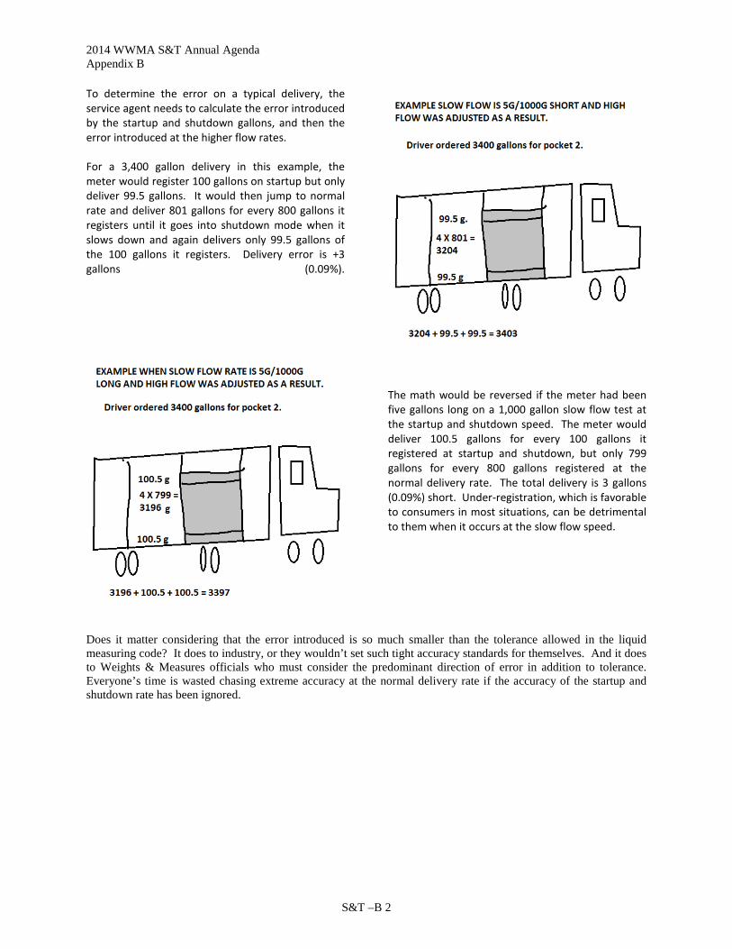
2014 WWMA S&T Annual Agenda Appendix B
S&T –B 2
To determine the error on a typical delivery, the service agent needs to calculate the error introduced by the startup and shutdown gallons, and then the error introduced at the higher flow rates.
For a 3,400 gallon delivery in this example, the meter would register 100 gallons on startup but only deliver 99.5 gallons. It would then jump to normal rate and deliver 801 gallons for every 800 gallons it registers until it goes into shutdown mode when it slows down and again delivers only 99.5 gallons of the 100 gallons it registers. Delivery error is +3 gallons (0.09%).
The math would be reversed if the meter had been five gallons long on a 1,000 gallon slow flow test at the startup and shutdown speed. The meter would deliver 100.5 gallons for every 100 gallons it registered at startup and shutdown, but only 799 gallons for every 800 gallons registered at the normal delivery rate. The total delivery is 3 gallons (0.09%) short. Under-registration, which is favorable to consumers in most situations, can be detrimental to them when it occurs at the slow flow speed.
Does it matter considering that the error introduced is so much smaller than the tolerance allowed in the liquid measuring code? It does to industry, or they wouldn’t set such tight accuracy standards for themselves. And it does to Weights & Measures officials who must consider the predominant direction of error in addition to tolerance. Everyone’s time is wasted chasing extreme accuracy at the normal delivery rate if the accuracy of the startup and shutdown rate has been ignored.

2014 WWMA S&T Annual Agenda Appendix C
S&T – C 1
Appendix C
Item 331-1: N.4.2.1. Determination of Error on Vehicle-Tank Meters with Multiple Flow Rates and Calibration Factors
How Slow Flow Errors Affect VTM’s Imagine a typical VTM which is calibrated using a 100 gallon prover for a bulk delivery company whose customers’ tanks are typically between 100 and 1,000 gallons. The meter has an electronic register programmed with a slow flow rate for start-up and shut-down, and a high-flow rate for typical deliveries. Startup and shutdown deliveries are 10 gallons each regardless of total quantity delivered.
Now imagine that the service agent calibrating the meter didn’t check the slow flow rate and didn’t know that the meter was long 0.4 gallons on a 100 gallon test. Instead, he calibrated the normal flow rate without testing the slow flow and introduced a linear error which increases the farther the transaction quantity deviates from the prover size. On a 100 gallon delivery the meter would appear to be accurate, but on a 500 gallon delivery a -0.4 gallon error has been introduced. That is within tolerance, but if all of his meters have similar errors in the same direction, typical deliveries will be in the operator’s favor at the expense of his customers.
When calibrating at the normal speed, the meter registers 20 gallons of product for the startup and shutdown, but actually delivers 20.08 gallons. (10.04 gallons delivered for every 10.00 gallons registered at slow speed.) If the service technician calibrates the meter to zero at normal speed, the meter will actually deliver 79.92 gallons for every 80.00 gallons it registers at that flow rate.
Every subsequent delivery of 100 gallons should receive exactly the right amount. Every delivery exceeding 100 gallons will be ‘short’ and every delivery less than 100 gallons will be ‘long.’

2014 WWMA S&T Annual Agenda Appendix C
S&T – C 2
To determine the error on a typical delivery, the service agent needs to calculate the error introduced by the startup and shutdown gallons, and then the error introduced at the higher flow rates.
For a 500 gallon delivery in this example, the meter would register 10 gallons on startup but actually deliver 10.04 gallons. It would then jump to normal rate and deliver 79.92 gallons for every 80 gallons it registers until it goes into shutdown mode when it slows down and again delivers 10.04 gallons as it registers only an additional 10 gallons.
The error would be well within maintenance tolerance so the Weights and Measures official need only be concerned if the slow flow errors on all the meters for a particular product are in the same direction. At that point, the official should determine the direction of the error on a typical delivery to determine if the equipment is being properly maintained. Device users can ensure they have no problems with this requirement by making sure that slow flow errors are not predominantly in one direction.

2014 WWMA S&T Annual Agenda Appendix D
S&T – D 1
Appendix D
Agenda Item 337-1: Submitters Background and Justification for Handbook 44 Definition of
“Diesel Gallon Equivalent (DGE)” of Compressed Natural Gas (CNG) and Liquefied Natural Gas (LNG) as a Vehicular Fuel
Clean Vehicle Education Foundation
Development of the “Gasoline Gallon Equivalent” by NCWM*
In 1993, under the auspices of the National Conference on Weights and Measures (NCWM), a Compressed Natural Gas (CNG) Working Group came together to determine the way in which CNG would be sold to the public at retail as a motor fuel. .
The working group focused on three issues:
1. How to provide the Natural Gas Vehicle (NGV) industry a method of sale that would be familiar and acceptable to consumers
2. How to provide weights and measures officials a verifiable and quantifiable means to determine the accuracy of natural gas dispensers; and
3. How to meet these requirements with a uniform, national standard.
NCWM considered three proposals for the method of sale of CNG: 1. Joules, the unit of energy measurement in SI units 2. Mass 3. The Gasoline Gallon Equivalent (GGE)
The Natural Gas Vehicle Coalition (now NGVAmerica) recommended that the Gasoline Gallon Equivalent be adopted as the method of sale for CNG, and that it be based on the energy equivalent of a gallon of gasoline. The use of the GGE was recommended primarily for the convenience of the retail customer comparing the cost and fuel economy of a natural gas vehicle to a comparable gasoline vehicle. During the discussion, a proposal was made to eliminate the reference to energy content of CNG and replace it with a fixed conversion factor based on mass, with the fixed mass of CNG being equal to a gallon of gasoline. Measurement of mass in the retail dispenser and verification by W&M officials is easier and less costly than measurement of energy content.
Since the energy content of a unit measure of CNG (standard cubic foot - scf) and gasoline (gallon) vary widely depending on the sample of fuel measured, the reference gallon of gasoline was determined to be Indolene, the gasoline used by EPA to certify emissions and fuel economy, with an energy content (lower heating value) of 114,118 BTU/gal. Work conducted by the Institute of Gas Technology and the Gas Research Institute (now combined into the Gas Technology Institute) surveyed 6811 samples of natural gas nationwide and concluded that the “average” natural gas in the US had an
* Report of the 78th National Conference on Weights and measures, 1993, NIST Special Publication 854, pp 322-326.
Report of the 79th National Conference on Weights and Measures, 1994, NIST Special Publication 870, pp 213-217.
Program and Committee Reports for the National Conference on Weights and Measures, 79th Annual Meeting, July 17-21, 1994, NCWM Publication 16, pp 89-92.
CVEF Page 1 11/25/13

2014 WWMA S&T Annual Agenda Appendix D
S&T – D 2
energy content (lower heating value) of 923.7 BTU/scf, and a density of 0.0458172 lbs/cubic foot. This translates 20,160.551 BTU/lb. Dividing gasoline’s 114.118 BTU/gal by natural gas’s 20,160.551 BTU/lb gives 5.660 lbs of natural gas = 1 GGE. Similar calculations determined that a gasoline liter equivalent of natural gas equals 0.678 kg of natural gas.
At its 79th annual meeting in July of 1994, NCWM adopted resolutions that: “All
natural gas kept, offered or exposed for sale or sold at retail as a vehicle fuel shall be in terms of the gasoline liter equivalent (GLE) or gasoline gallon equivalent (GGE), and
All retail natural gas dispensers shall be labeled with the conversion factor in terms of kilograms or pounds. The label shall be permanently and conspicuously displayed on the face of the dispenser and shall have either the statement “1 Gasoline Liter Equivalent (GLE) is equal to 0.678 kg of Natural Gas” or “1 Gasoline Gallon Equivalent (GGE) is equal to 5.660 lbs of Natural Gas” according to the method of sale used.”
These statements can be found in NIST Handbook130*, along with the definition of “natural gas” which seems to apply only to Compressed Natural Gas, not to Liquefied Natural Gas. Handbook 130, §§3.11 and 3.12 (Engine Fuels, Petroleum Products, and Automotive Lubricants Regulations) confirm that these requirements are for CNG, rather than LNG. Similar requirements and definitions are found in Handbook 44.
During the discussions it was recognized that, although diesel and gasoline are both sold in gallon units, a gallon of diesel fuel has substantially more energy content than a gallon of gasoline. While it is convenient to use the Gasoline Gallon Equivalent unit when comparing the cost and fuel economy of gasoline-powered light-duty vehicles to equivalent natural gas vehicles, a Diesel Gallon Equivalent unit would be more useful for operators of medium and heavy-duty (usually diesel powered) vehicles. However, in 1994, the NCWM working group “agreed to defer development of a “Diesel Gallon Equivalent” until the issues related to the ‘Gasoline Gallon Equivalent’ were decided by the NCWM and agreed to meet again if additional work is necessary.”** The issue of the formal definition a Diesel Gallon Equivalent (DGE) unit has not come before NCWM from that time until today, although the DGE is often used in the industry, defined as 6.31 lbs of compressed natural gas.
Need for a Definition of a “Diesel Gallon Equivalent” Unit
Today there are an increasing number of commercial vehicles using natural gas as a fuel, to lower emissions and Greenhouse Gases, decrease America’s use of petroleum, and lower fuel costs (U.S. DOE Clean Cities Alternative Fuel Price Report for April 2012
* “Method of Sale Regulation,” §2.27 ** Report of the 79th National Conference on Weights and Measures, 1994, NIST Special Publication 870, p 214
CVEF Page 2 11/25/13

2014 WWMA S&T Annual Agenda Appendix D
S&T – D 3
shows in Table 2 ‘Overall Average Fuel Price on Energy-Equivalent Basis’ that diesel is priced at $4.12/gal and CNG at $2.32/gal http://www.afdc.energy.gov/afdc/pdfs/afpr_apr_12.pdf ). Since the NCWM’s working group deferred development of a DGE unit in 1994, there has been little call by the natural gas vehicle industry for the formalization of that unit in the sale of Compressed Natural Gas. However the use of Liquefied Natural Gas (LNG) as a motor fuel has been growing (more than 350 LNG stations are being built on the nations interstate Highways) and there is significant interest in using the DGE as a unit for the sale of that fuel.
LNG as a motor fuel is used almost exclusively by commercial vehicles, most of which view diesel as the conventional alternative. Using the same logic as was used for the development of the GGE unit, the convenience of the retail customer comparing the cost and fuel economy of a natural gas vehicle to a comparable conventional vehicle, it makes sense for NCWM to now “officially” define the DGE.
Other than §3.12. Liquefied Natural Gas, in the Engine Fuels and Automotive Lubricants Regulation section of Handbook 130, we find no specific provisions in either Handbook 44 or Handbook 130 for the retail sale of LNG as a motor fuel. However LNG is sold in California and other states on a mass basis (by the pound), which allows for easy confirmation by weights and measures authorities. An “official” definition of the DGE as a specific mass of LNG and CNG would allow states to easily move from retail sale by pound to retail sale by DGE, simplifying the sale process for the retail customer used to dealing with “gallons of diesel” as a fuel measure.
Therefore, at this time we are asking for a definition of the Diesel Gallon Equivalent (and Diesel Liter Equivalent) units by NCWM.
Justification of the Definition of a DGE as 6.38 Pounds of Compressed Natural Gas Handbook 130
contains the following definitions of natural Gas as a vehicle fuel*: Gasoline liter equivalent
(GLE). – Gasoline liter equivalent (GLE) means 0.678 kg of natural gas.
Gasoline gallon equivalent (GGE). – Gasoline gallon equivalent (GGE) means 2.567 kg (5.660 lb) of natural gas.
As the NCWM working group recognized during its deliberations in 1993 on the Gasoline Gallon Equivalent unit, both gasoline and natural gas can vary in their BTU content from sample to sample. The working group determined the gasoline gallon (energy) equivalent based on a gallon of Indolene (114,118 BTU/gal – lower heating value) and a survey of 6811 natural gas samples nationwide with an average of 923.7 BTU/scf (lower heating value) and a density of 0.0458172 lbs/cubic foot. This equates
* NIST handbook 130, 2006, Method of State Regulation, §§2.27.1.2 and 2.227.1.3; also Engine Fuels, Petroleum Products, and Automotive Lubricants Regulation, §§1.25 and 1.26.
CVEF Page 3 11/25/13

2014 WWMA S&T Annual Agenda Appendix D
S&T – D 4
to 20,160.551 BTU/lb. Dividing gasoline’s 114.118 BTU/gal by natural gas’s 20,160.551 BTU/lb gives 5.660 lbs of natural gas = 1 GGE. Similar calculations determined that a gasoline liter equivalent of natural gas equals 0.678 kg of natural gas.
Starting with 5.660 lbs of natural gas = 1 GGE and 0.678 kg of natural gas = 1 GLE, we can calculate the mass of natural gas necessary to make a DGE and a DLE by comparing the amount of energy in a gallon of diesel fuel to the amount of energy in a gallon of gasoline fuel and apply that ratio to scale up the masses of natural gas calculated for the GGE and GLE units.
Unfortunately it is no easier today than it was in 1993 to set one energy value as representative of a unit for all gasoline, (or diesel) fuel. EPA’s certification fuel has likely changed in energy content since 1993, as both gasoline and diesel fuels have been modified for improved emissions.
We recommend using the most recent Department of Energy Transportation Energy Data Book*, as an authoritative reference for both gasoline and diesel fuel energy values. Taking further surveys or basing our calculations on today’s EPA certification fuel only delays our action, substantially increases costs, and, in the end, provides a limited potential increase in accuracy based on one point in time. Table B.4 of the Transportation Energy Data Book, on the heat content of fuels lists the net energy of diesel as 128,700 BTU/Gal. The 31st Edition may be downloaded at the following site. http://cta.ornl.gov/data/download31.shtml
Therefore a Diesel Gallon Equivalent of compressed natural gas is: (128,700
BTU/Gal / 20,160.551 BTU/lb) = 6.38 lb/DGE (2.894 kg/DGE) and a Diesel Liter
Equivalent of compressed natural gas is:
2.894 kg/DGE X 0.2642 Gal/Liter = 0.765 kg/DLE Justification of the Definition of a DGE as 6.06 Pounds of Liquefied Natural Gas
Cooling pipeline natural gas to -259 0F makes liquefied Natural Gas (LNG). The pipeline natural gas has the same national average composition as was determined for CNG with a LHV of 20,160.551 BTU/lb. In order to reduce the natural gas temperature for liquefaction carbon dioxide must be removed since it would solidify in the system and nitrogen, which remains a gas at LNG temperatures, is reduced to less that 0.5% by volume in the final product. These changes to the composition of the pipeline gas increase the LHV of LNG to 21,240 BTU/lb.
* Stacy C. Davis and Susan W. Diegel, Oak Ridge National Laboratory, Transportation Energy Data Book, Edition 31, 2012, ORNL-6987, or http://cta.ornl.gov/data/index.shtml
CVEF Page 4 11/25/13

2014 WWMA S&T Annual Agenda Appendix D
S&T – D 5
Therefore a Diesel Gallon Equivalent of LNG is:
128,700 BTU/lb / 21,240 BTU/lb = 6.06 lb/DGE (2.749 kg/DGE)
and a Diesel Liter Equivalent of LNG is:
2.749 kg/DGE X 0.2642 Gal/Liter = 0.7263 kg/DLE
The attached presentation file provides an overview of the CNG and LNG processes from pipeline to dispensing along with the calculation of the LNG LHV based on the change in LNG chemical composition through the liquefaction process.
Prepared by: Clean Vehicle Education Foundation http://www.cleanvehicle.org
CVEF Page 5 11/25/13

2014 WWMA S&T Annual Agenda Appendix D
S&T – D 6
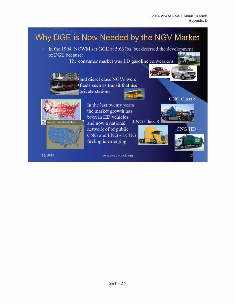
2014 WWMA S&T Annual Agenda Appendix D
S&T – D 7

2014 WWMA S&T Annual Agenda Appendix D
S&T – D 8

2014 WWMA S&T Annual Agenda Appendix D
S&T – D 9

2014 WWMA S&T Annual Agenda Appendix D
S&T – D 10

2014 WWMA S&T Annual Agenda Appendix D
S&T – D 11
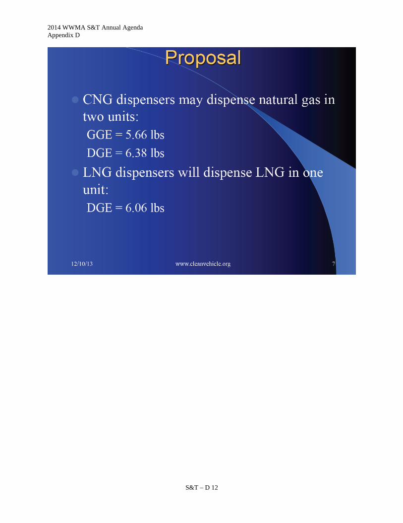
2014 WWMA S&T Annual Agenda Appendix D
S&T – D 12

2014 WWMA S&T Annual Agenda Appendix D
S&T – D 13

2014 WWMA S&T Annual Agenda Appendix D
S&T – D 14

2014 WWMA S&T Annual Agenda Appendix E
S&T – E 1
Appendix E
Item 337-2: Mass Flow Meters Code Paragraph S.3.6. Automatic Density
The following background information is excerpted from the NIST SP 920 the 1997 Report of the 82nd NCWM in the Final Report of the Specifications and Tolerances Committee in Agenda Item 337-2:
337-2 VC S.3.6.(b) Automatic Density Correction; Volume-Measuring Devices
(This item was adopted as part of the consent calendar.)
Source: Southern Weights and Measures Association Recommendation: Modify S.3.6.(b) Automatic Density Correction on Volume-Measuring Devices as follows:
S.3.6. Automatic Density Correction
(b) Volume-measuring devices with automatic temperature compensation used to measure natural gas as a motor vehicle engine fuel shall be equipped with an automatic means to determine and correct for changes in product density, both for due to changes in the temperature, pressure, and composition of the product.
[Nonretroactive as of January 1, 1995. To become retroactive as of January 1, 1999.] (Amended 1994 and1997)
Discussion: The Southern Weights and Measures Association submitted this proposal after reviewing a proposal from Hoffer Flow Controls to delete S.3.6. Automatic Density Correction on Volume-Measuring Devices from Handbook 44. Hoffer Flow Control’s position was that neither a direct mass flow meter or an inferred mass flow meter is capable of determining composition of a gas without the use of a gas chromatograph or similar type of analytical equipment which can make qualitative and quantitative determinations of the components that makeup a gas. The Southern believes that there are some misinterpretations of this paragraph relating to the use of the term “composition.” The Southern noted that paragraph S.3.6. recognizes that product density can vary with changes in product composition and with changes in product temperature. Any changes in product density can affect the accuracy of the meter, thus these devices must be equipped with a means to automatically correct for changes in product density. Manual entries of product density are not sufficient to compensate for changes in density which may vary with changes in the supply of product. Based on its review of past NCWM S&T reports the Southern believes the use of the term “composition” was not intended to require a device to automatically monitor changes in the qualitative properties of the gas; the requirement for monitoring changes in product density relates only to the subsequent impact on the measurement determination. Therefore, the Southern does not believe it is appropriate to delete the word “composition” and recommends as an alternative that the focus of the changes to S.3.6. should be to clarify the concerns which have been raised. The Southern notes that it heard additional comments that pressure may also affect product density and recommended that the S&T Committee study whether or not the term “pressure” should be added to S.3.6. During the open hearing session at the Interim Meeting, comments were heard that indicate other influence factors (in addition to temperature and composition) may affect product density. Based on this information, the Committee recommends that the term “pressure” be added to paragraph S.3.6. to require that these systems have an automatic means to determine and correct for changes in product density due to changes in “pressure.” The Committee recommends that this requirement be revisited as new technologies are developed that indicate other influence factors affect product measurement in these systems.

2014 WWMA S&T Annual Agenda Appendix E
S&T – E 2
The Committee heard comments from one manufacturer of an indirect mass flow meter that this item should be made informational until it completes research on these measuring systems. The Committee acknowledged that the study in progress and noted that it may revisit this issue when the study is complete on the effects of product composition.
The following background information is excerpted from NIST SP 870 the 1994 Report of the 79th NCWM in the Final Report of the Specifications and Tolerances Committee in Agenda Item 337-4B:
337-4B V S.3.6. Automatic Density Correction
(This item was adopted.)
Based upon comments received, add the following as a new Item 337-4B to address volume-measuring devices used to measure compressed natural gas as an engine fuel. Recommendation: To recognize volume-measuring devices being used to measure Compressed Natural Gas (CNG) as an engine fuel consistent with the requirements of the Hydrocarbon Gas Vapor-Measuring Devices Code and to permit time for these devices to be modified to incorporate automatic density correction, the Committee recommends that S.3.6. be amended to read:
S.3.6. Mass Flow Meters Automatic Density Correction. (a) An automatic means to determine and correct for changes in product density shall be incorporated
in any mass flow metering system that is affected by changes in the density of the product being measured.
(b) Volume-measuring devices with automatic temperature compensation used to measure natural gas
as a motor vehicle engine fuel shall be equipped with an automatic means to determine and correct for changes in product density, both for the temperature and composition of the product.
(Nonretroactive as of January 1, 1995. To become retroactive as of January 1, 1999.) Discussion: In the absence of a permanent Mass Flow Meters Code, requirements for mass flow meters have been adopted into several codes for measuring devices. The requirements of the Hydrocarbon Gas Vapor-Measuring Devices Code have been applied to devices used to measure CNG. This code permits volume measuring devices to indicate in units of volume, but the method of sale for CNG is currently being considered by the NCWM to be the gasoline gallon equivalent (GGE). The GGE is based upon mass units, hence, the automatic correction for changes in composition of the natural gas is needed to promote more accurate measurement. To provide time to incorporate automatic density correction for these devices, subparagraph (b) is added as a nonretroactive requirement. During the time volumetric devices are used to measure compressed natural gas as a motor vehicle engine fuel, corrections for changes in product density due to changes in composition will have to be entered manually. It is the owner’s responsibility to maintain the device within tolerance at all times. Subparagraph (b) will become retroactive as of January 1, 1999.
2014 WWMA S&T Annual Agenda Appendix F
S&T – F 1
Appendix F
Item 358-1: Measurement of Bulk Material in Open-Top Truck and Trailer Units
Load Volume Scanner Metrology, Test methods & Suitability for Use
by Loadscan Ltd.
2014 WWMA S&T Annual Agenda Appendix F
S&T – F 2

2014 WWMA S&T Annual Agenda Appendix F
S&T – F 3

2014 WWMA S&T Annual Agenda Appendix F
S&T – F 4

2014 WWMA S&T Annual Agenda Appendix F
S&T – F 5
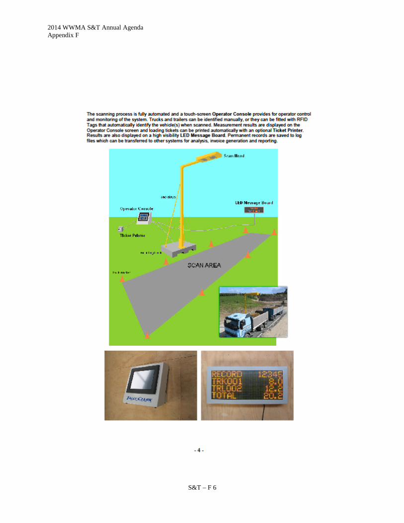
2014 WWMA S&T Annual Agenda Appendix F
S&T – F 6

2014 WWMA S&T Annual Agenda Appendix F
S&T – F 7

2014 WWMA S&T Annual Agenda Appendix F
S&T – F 8

2014 WWMA S&T Annual Agenda Appendix F
S&T – F 9

2014 WWMA S&T Annual Agenda Appendix F
S&T – F 10

2014 WWMA S&T Annual Agenda Appendix F
S&T – F 11

2014 WWMA S&T Annual Agenda Appendix F
S&T – F 12

2014 WWMA S&T Annual Agenda Appendix F
S&T – F 13

2014 WWMA S&T Annual Agenda Appendix F
S&T – F 14

2014 WWMA S&T Annual Agenda Appendix F
S&T – F 15
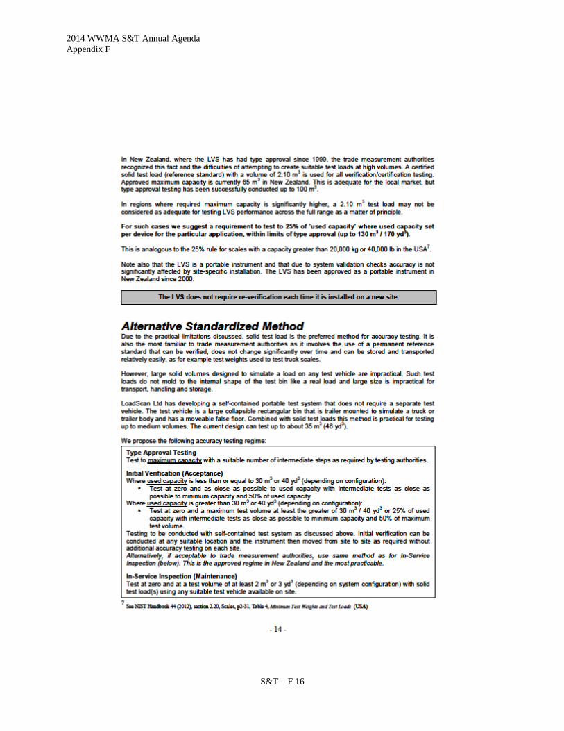
2014 WWMA S&T Annual Agenda Appendix F
S&T – F 16

2014 WWMA S&T Annual Agenda Appendix F
S&T – F 17

2014 WWMA S&T Annual Agenda Appendix F
S&T – F 18

2014 WWMA S&T Annual Agenda Appendix F
S&T – F 19

2014 WWMA S&T Annual Agenda Appendix F
S&T – F 20

2014 WWMA S&T Annual Agenda Appendix F
S&T – F 21
2014 WWMA S&T Annual Agenda Appendix F
S&T – F 22

2014 WWMA S&T Annual Agenda Appendix F
S&T – F 23

2014 WWMA S&T Annual Agenda Appendix F
S&T – F 24
This Page Intentionally Left Blank

2014 WWMA S&T Annual Agenda Appendix G
S&T – G 1
Appendix G
Item 358-1 Load Volume Scanner, Proposals for Integration into Handbook 44
Load Volume Scanner Proposals for Integration into Handbook 44
A submission to NCWM
Author:
Adrian Ruthe
Technical Manager
LoadScan Ltd, New Zealand
Contents
Introduction 2
Applicability of MDMD Code to the LVS 3
Tolerances 3
Limitations on Use 4
Test Procedures – Accuracy Testing 5
Test Procedures – Disturbance Testing 7
Appendix - LVS Type Approval History Outside of the USA 8
New Zealand 8
Australia 9

2014 WWMA S&T Annual Agenda Appendix G
S&T – G 2
Introduction At the time of writing, the LoadScan Load Volume Scanner (LVS) has been granted ‘Developing Item’ status by NCWM and it is now up to LoadScan as the device manufacturer to prepare specific language for Handbook 44 amendment. Multiple Dimension Measuring Devices (MDMD) has been identified as the most suitable classification into which to incorporate the LVS and our aim is to prepare amendments to the MDMD specification, or if not feasible, to submit a new instrument specification modeled on MDMD.
At this stage formal language has not been developed. This document identifies only the most significant areas where the MDMD code cannot be directly applied to the LVS and proposes solutions for consideration by the relevant authorities. Other minor discrepancies between LVS and MDMD can be readily addressed by minor amendments to the MDMD code. Formal code will be developed and minor discrepancies between LVS and MDMD addressed only when consensus and approval in principle has been reached on the key issues.
It is strongly recommended to read the appendix to this document, LVS Type Approval History Outside of the USA before considering the proposals below. Some topics are also discussed in more detail in the supporting document to this submission, Load Volume Scanner - General Metrology, Test Methods and Suitability for Use (revision of a previously submitted document, not US specific).
2014 WWMA S&T Annual Agenda Appendix G
S&T – G 3
Applicability of MDMD Code to the LVS The LVS has some notable similarities to MDMD:
• MDMD typically uses the same non-contact laser measurement technology as the LVS. • MDMD and LVS both compute volume from a set of linear dimensional measurements. • MDMD and LVS both typically measure moving targets passing below the measurement elements of the
instrument. • MDMD and LVS both measure the target relative to a zero reference profile formed by the surface or
container that carries the object or load being measured.
There are also some notable differences: • MDMD measures discrete objects (boxes, packages etc) whereas LVS measures bulk loose flowable solid
materials (materials that form heaps). • MDMD uses a set of rules to compute the volume of a hexahedron occupied by the measured object
whereas LVS measures the actual volume of the heap of measured material (“loose” volume based on the surface contour).
• MDMS intended for calculating freight, storage, or postal charges based on the dimensions and/or volume occupied by the object whereas LVS intended for determining quantities of material where that material is traded by volume.
• MDMS zero reference is generally a flat conveyor-belt or table top and can be treated as a static 2D profile whereas LVS zero reference is the entire load-bearing container (truck trailer or bin) that moves with the measured load and must be treated as a moving 3D profile.
So consider Handbook 44, Section 5.58. Multiple Dimension Measuring Devices, Application:
A.2. Other Devices Designed to Make Multiple Measurement Automatically to Determine a Volume. – Insofar as they are clearly applicable, the provisions of this code apply also to devices designed to make multiple measurements automatically to determine a volume for other applications as defined by Section 1.10. General Code paragraph G-A.1. Commercial and Law-Enforcement Equipment.
This applies to the LVS. However, the need for an instrument description that more explicitly describes the LVS principle of operation and application should be considered, if only to define a clear sub-category that variations in the MDMD code can be specifically applied to. As the manufacturer of a specific instrument, it may not be appropriate for us to define the limitations or terminology of this specific sub-category. But for the purposes of this document “LVS” will refer to such a sub-category of MDMD instruments that the Load Volume Scanner belongs to.
Tolerances Handbook 44, Section 5.58. Multiple Dimension Measuring Devices, Tolerances:
T.3. Tolerance Values. – The maintenance and acceptance tolerance values shall be ± 1 division.

2014 WWMA S&T Annual Agenda Appendix G
S&T – G 4
It is not be feasible for the LVS to meet these requirements (and the requirements of paragraph S.1.5 and T.2.3) without a multi-interval implementation and choices of division sizes for each interval that may not be suitable for intended application in some cases.
We propose the following variation for instruments of the LVS class:
The maintenance and acceptance tolerance values shall be ± 1 division or 1 percent of measured load; whichever is the greater.
In practice, the minimum feasible scale division for the LVS is 0.1 cubic meter or 0.1 cubic yard, dependent on regional configuration. To meet the requirements of the US bark and mulch industries the maximum capacity will need to be 130 cubic meters or 170 cubic yards per individual truck bin.
We realize that this effectively puts the LVS in a lower accuracy classification than allowed for other classes of instrument such as weigh scales used for trade.
The closest comparable class I can find in HB 44 for the volumetric measure of dry solid material is Dry Measures (section 4.45). Obviously the LVS does not fit into this classification. However, as a point of note, the maintenance tolerances for a 1 bushel dry measure (the largest measure specified) are 50 cubic inches in excess and 25 cubic inches in deficiency with acceptance tolerances being one-half the maintenance tolerances (Handbook 44, section 4.45. Dry Measures, Tolerances). Averaging over “in excess” and “in deficiency” this is equivalent to maintenance and acceptance tolerances of approximately 1.74% and 0.87% respectively. And by extension, the same tolerances apply to quantities resulting from multiple 1 bushel dry measures.
What must be considered is the intended purpose and suitability for use of the instrument. This is discussed in the supporting document to this submission, Load Volume Scanner - General Metrology, Test Methods and Suitability for Use.
Limitations on Use Consider the following excerpts from Handbook 130:
2.18.2. – All mulch shall be sold, offered, or exposed for sale in terms of volume measure in SI units in terms of the cubic meter or liter or in inch-pound units in terms of the cubic yard or cubic foot. 2.29 (a) – Top soil, fill dirt, aggregate or chipped rock, sand (including concrete and mortar sand), decomposed granite, landscape type rock, and cinders must be sold by the cubic meter or cubic yard or by weight.

2014 WWMA S&T Annual Agenda Appendix G
S&T – G 5
The LVS was designed to meet the requirements of specific industries such as the mulch and civil construction industries and their suppliers, who either trade by volume already, or would prefer to, if suitable measurement equipment were available. The LVS is intended to meet the requirements of these industries and is not intended as a general use instrument to replace truck scales. As such we propose the following limitations on use for instruments of the LVS class:
a) To soil, clay, sand, aggregate or chipped rock and similar excavated or mined materials b) Mulch, compost, specialty horticultural and landscaping mixes and primary constituent materials
thereof. c) Woodchip, sawdust, bark and similar materials d) Coal, unprocessed ore, mining waste e) Bulk recycled or waste materials in crushed, shredded or similar form f) Lumpy, irregular mixed materials only where traded as waste or debris
A shorter list may be possible if worded so as to be suitably inclusive.
Test Procedures – Accuracy Testing
Handbook 44, Section 5.58. Multiple Dimension Measuring Devices, Notes:
N.1.1. General. – The device shall be tested using test standards and objects of known and stable dimensions.
N.1.4.1. Test Objects. – Verification of devices may be conducted using appropriate test objects of various sizes and of stable dimensions. Test object dimensions must be known to an expanded uncertainty (coverage factor k = 2) of not more than one-third of the applicable device tolerance. The dimensions shall also be checked to the same uncertainty when used at the extreme values of the influence factors. The dimension of all test objects shall be verified using a reference standard that is traceable to NIST (or equivalent national laboratory) and meet the tolerances expressed in NIST Handbook 44 Fundamental Considerations, paragraph 3.2. (i.e., one-third of the smallest tolerance applied to the device).
Due to the practical difficulties in generating LVS test loads of known and stable dimensions, as discussed in the Test Methods section of the supporting document Load Volume Scanner - General Metrology, Test Methods and Suitability for Use, we propose that the system of test objects/standards used for certification testing in Australia be adopted (see notes and photos in Australia section of the appendix to this document, LVS Type Approval History Outside of the USA). This system combines a rectangular bin trailer with moveable false floor and rigid test objects and is suitable for generating test loads with volume known to the required level of expanded uncertainty for the tolerances proposed above. The dimensions of all test objects/bins can readily be verified with a tape measure (NIST traceable reference standard).
Code language to facilitate this could be along the lines of:

2014 WWMA S&T Annual Agenda Appendix G
S&T – G 6
Test objects approximating the shape of a heaped load and with geometry that facilitates determination of volume by measurement of linear dimensions may be used to generate test loads in a suitable mobile test container. A raised floor or rigid objects covering the entire test container floor such that no edges are visible may be placed in the test container, supporting the test objects, to generate test loads at larger volumes.
This method of using dedicated test equipment is only suitable for generating test volumes of a limited size. At this stage we have only used this method to test up to 35 cubic meters (45 cubic yards).
Handbook 44, Section 5.58. Multiple Dimension Measuring Devices, Notes:
N.1.4. Test Object Size. – Test objects may vary in size from the smallest dimension to the largest dimension marked on the device, and for field verification examinations, shall be an integer multiple of “d.”
This does not explicitly require testing to maximum capacity. As discussed in the supporting document to this submission, Load Volume Scanner - General Metrology, Test Methods and Suitability for Use, correct operation within accuracy capability for the LVS can theoretically be confirmed at any test volume. We propose the following variation for LVS class instruments:
Test loads shall vary in size from zero (empty test container) to at least 25% of instrument capacity including minimum capacity and at least one other intermediate volume.
For a maximum capacity of 130 cubic meters or 170 cubic yards this would be feasible. This is similar to the requirement for scales with a capacity above 20,000kg or 40,000lb as specified in Handbook 44, Section 2.2. Scales,

2014 WWMA S&T Annual Agenda Appendix G
S&T – G 7
Notes, Table 4. It may be considered necessary to specify the 25% rule for instruments with a capacity above a set value as for scales. See further discussion of a Standardized Test Method and other test methods in the supporting document to this submission, Load Volume Scanner - General Metrology, Test Methods and Suitability for Use.
Note that in New Zealand all official certification/verification testing is performed with a single rigid test object of 2.1 cubic meters, which equates to 3.2% of approved maximum capacity of 65m3 per bin (see appendix to this document, LVS Type Approval History Outside of the USA).
Type approval testing may need to be conducted to maximum capacity. This is possible by finding a suitable, very large truck-trailer and manually dimensioning this trailer in detail and generating test loads by a combination of methods. This is very time consuming and requires a lot of resources. This is feasible for one-time type approval testing but not for regular verification testing.
Additionally, it is not practical to generate larger test loads to an integer multiple of the scale interval “d” by the proposed test method. However, the LVS instrument has a test mode that displays measurements at a higher resolution, allowing accurate comparison between measurement indications and computed test load volumes. We propose a requirement along the lines of the following:
The instrument shall have a special test mode that can only be activated for accuracy testing and causes all measurement indications to be output to a resolution of at least 10 times “d”.
Test Procedures – Disturbance Testing It is simply not feasible to put a standard LVS system in an environmental chamber and perform disturbance tests for type approval. Requirements for any laboratory testing will need to be discussed. Please see the Australia section of the appendix to this document, LVS Type Approval History Outside of the USA for notes on how this was handled for type approval in Australia. We propose a similar approach be adopted for NTEP testing.
2014 WWMA S&T Annual Agenda Appendix G
S&T – G 8
APPENDIX - LVS TYPE APPROVAL HISTORY OUTSIDE OF THE USA
NEW ZEALAND The LVS was granted type approval in New Zealand in 1999. Approval was based loosely on the OIML specification for Automatic Catchweighing Instruments (OIML R51-1). This was prior to the release in 2000 of the OIML specification for Multi-Dimensional Measuring Instruments (OIML R129) which is the equivalent of MDMD. The New Zealand Certificate of Approval 1556 (type approval) is available for reference. No type approval guide document exists.
The following are some specific points of note.
1. Initial approval was only up to 20m3 load per bin (maximum capacity) with limitation to measurement of sand, gravel and small rock. However, Trading Standards New Zealand (TSNZ) monitored our systems for some time, were happy with the performance and since 2007 approval has been up to 65m3 per bin, for any solid material with a particulate size of less than or equal to 200mm. Minimum capacity is 0.5m3.
2. We have successfully performed field testing with the TSNZ up to 105m3 per bin but have not applied for a type approval variant up to this volume as it is not currently required for the size of trucks operated in New Zealand.
3. We have about 50 trade-legal certified LVS systems operating in New Zealand. There have been no complaints to TSNZ in the 13 years since initial type approval.
4. The accuracy class specified is a variant on Catchweigher class Y(b). For our implementation with a scale interval of 0.1m3 this is similar to US weight class IIII up to 40m3 and better than class IIII above 40m3.
5. Type approval does not require accuracy testing up to maximum capacity. This recognizes the fact that due to the principle of operation of the LVS, measurement accuracy can effectively be confirmed at any volume (see support document Load Volume Scanner - General Metrology, Test Methods and Suitability for Use). Type evaluation testing was of course conducted to maximum capacity.
6. Several methods for generating test loads are approved. However LoadScan maintains a single 2.1m3 test load (reference standard) for all certification/verification testing. This is a rigid profile approximating the shape of a load. The test load is annually re-certified by TSNZ. Volume is determined by the displacement of water in a rectangular tank.

2014 WWMA S&T Annual Agenda Appendix G
S&T – G 9
AUSTRALIA The LVS was granted type approval in Australia in 2010. Type Approval was based as closely as practical on the OIML specification for Multi-Dimensional Measuring Instruments (OIML R129). Before conducting type evaluation the Australian National Measurement Institute (NMI) prepared a type evaluation guide called Guidelines for the Pattern Approval of Systems used for the Determination of Load Volumes. This is based primarily on the Australian general guidelines for pattern approval and the OIML specification for Multi-Dimensional Measuring Instruments (OIML R129). This document and Certificate of Approval No 13/1/15 (type approval) are available for reference. The following are some specific points of note.
1. Current approval is only up to 35m3 load per bin. This is not a limitation imposed by NMI but the result of the resources we had available when field evaluation was conducted only being suitable for loads up to 35m3. This is adequate to cover the requirements of the construction and most other industries except the mulch industry. Minimum capacity is 1.0m3. Further testing will be conducted with NMI for higher volumes.
2. The LVS is approved for measurement of ‘flowable solids such as sand, soil, gravel and agricultural materials’.
3. Approval requires accuracy testing “near (as close as practical)” to maximum capacity. The volume of test loads must be determined to an expanded uncertainty of one fifth of the maximum permissible error or less, in line with the OIML specification for Multi-Dimensional Measuring Instruments (OIML R129).
4. The approval certificate does not require an accuracy class to be marked on the instrument. Only maximum permissible errors (tolerances) are specified. NMI’s view is that no formal accuracy classes exist for this type of instrument so it does not make sense to mark a class. This also allows the instrument to be tested to different accuracy “classes” within the maximum tolerances specified, depending on the intended application and the type/quality of test loads available.

2014 WWMA S&T Annual Agenda Appendix G
S&T – G 10
5. The maximum tolerances specified in the approval are based on weight class 5 from the OIML specification for Automatic instruments for weighing road vehicles in motion and measuring axle loads (OIML R134). This is a low accuracy class (basically a 2.5% class). The reason for this is not the accuracy of the LVS system but the difficulty in generating test loads with sufficiently accurately known volume (expanded uncertainty 1/5th MPE) to perform accuracy testing up to maximum capacity. However, the LVS may be also be tested to class 2 (1% class) if suitable test loads/standards are available.
6. It is up to individual state authorities to specify any additional limitations on use, depending on the accuracy class the LVS is tested to.
7. LVS approval requires that all measured volume indications are accompanied by a statement that the volume indicated is that at the time of measurement. This reflects the fact that flowable solid volumes can fluctuate slightly over time (see support document Load Volume Scanner - General Metrology, Test Methods and Suitability for Use).
8. For practical reasons laboratory testing in an environmental chamber for type approval was conducted with a modified mounting system for the LVS to allow it to fit into the test chamber. The testing was also conducted with static (non-moving) test profiles and a modified version of the system software. NMI took the approach that the ability of the LVS software to compute accurate volumes from the raw laser distance measurement data can be determined by field-testing and that for laboratory testing it is only necessary to test the ability of the laser distance measuring components to provide suitable data for the software to process. A variation on the disturbance and other tests given in the OIML specification for Multi-Dimensional Measuring Instruments (OIML R129) were conducted.
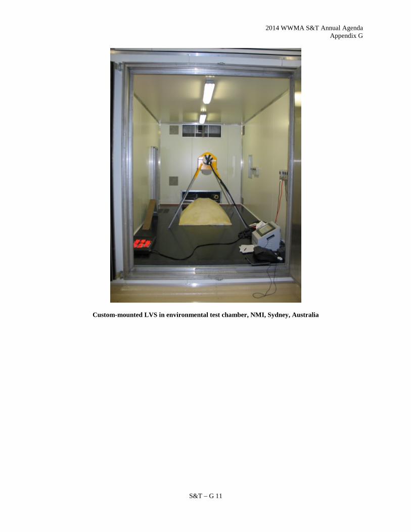
2014 WWMA S&T Annual Agenda Appendix G
S&T – G 11
Custom-mounted LVS in environmental test chamber, NMI, Sydney, Australia

2014 WWMA S&T Annual Agenda Appendix G
S&T – G 12
9. LoadScan maintains a ‘test trailer’ and a 1.0m3 test load (reference standard) for certification testing in Australia. The test trailer is a dimensionally accurate rectangular bin with a false floor that can be positioned at different heights to simulate different levels of loading. The 1.0m3 test load is placed on the trailer floor or false floor to create a more realistic load profile and to test at minimum capacity. The trailer is fully mobile and can be disassembled. The 1.0m3 test load is dimensionally accurate and design is based on basic geometrical shapes so that its volume can be determined by manual measurement with tape measure. Test load volumes can be determined with enough accuracy to test to class 2 (1% class) with this equipment.

2014 WWMA S&T Annual Agenda Appendix G
S&T – G 13
2014 WWMA S&T Annual Agenda Appendix G
S&T – G 14
2014 WWMA S&T Annual Agenda Appendix H
S&T – H 1
Appendix H
Item 360-3: Electric Vehicle Fueling and Submetering
This draft code is currently under development by the USNWG; this draft is NOT yet ready for consideration by the
NCWM. Updated versions will be posted on the NIST website as work by the USNWG progresses.
Draft NIST Handbook 44 Device Code Requirements for Electric Vehicle Fueling and Submetering
This tentative code has only a trial or experimental status and is not intended to be enforced. The requirements are designed for study prior to the development and adoption of a final code. Officials wanting to conduct an official examination of a device or system are advised to see paragraph G-A.3. Special and Unclassified Equipment.
(Tentative Code Added 20XX)
A. Application
A.1. General. – This code applies to electronic and mechanical devices, accessories, and systems used for the measurement of electricity dispensed as a vehicle fuel and in other commercial electricity sub-metering applications wherein a quantity determination or statement of measure is used wholly or partially as a basis for sale or upon which a charge for service is based. A.2. Exceptions. – This code does not apply to:
(a) This code does not apply to the use of any measure or measuring device used by a public utility in connection with measuring electricity subject to the jurisdiction of the Public Utilities Commission.
(b) Devices used solely for dispensing a product in connection with operations in which the amount dispensed
does not affect customer charges.
(c) The wholesale delivery of electricity. A.3. Additional Code Requirements. – In addition to the requirements of this code, Electricity-Measuring Devices shall meet the requirements of Section 1.10. General Code.
A.3.1. Dual-Purpose Electric Vehicle Supply Equipment (EVSE) and Timing Devices. – A device that is used for both the sale of electricity as vehicle fuel and the sale of other separate time-based services (e.g., vehicle parking) shall meet the requirements Section 5.55. Timing Devices. in addition to the requirements of this code.
A.4. Type Evaluation. – The National Type Evaluation Program (NTEP) will accept for type evaluation only those devices that comply with all requirements of this code. A.5. Meter Type Notation. – Code sections and subsections with an [EM] notation apply to electronic meters only. Code sections and subsections with a [MM] notation apply to mechanical meters only. Code sections and subsections without [EM] or [MM] notation apply to both meter types.

2014 WWMA S&T Annual Agenda Appendix H
S&T – H 2
S. Specifications
S.1. Indicating and Recording Elements.
S.1.1. Electric Vehicle Supply Equipment (EVSE). – A device used to charge electric vehicles shall be of the computing type and shall indicate the electrical energy, the unit price, and the total price of each delivery. S.1.2. EVSE Indicating Elements. – A device used to charge electric vehicles shall include an indicating element that continuously displays measurement results relative to quantity and total price. Indications shall be clear, definite, accurate, and easily read under normal conditions of operation of the device. All indications and representations of electricity sold shall be clearly identified and separate from other time-based fees indicated by a dual-purpose device that is used for both the sale of electricity as vehicle fuel and the sale of other separate time-based services (e.g., vehicle parking). S.1.3. EVSE Units.
S.1.3.1. EVSE Units of Measurement. – Deliveries used to charge electric vehicles shall be indicated and recorded in megajoules (MJ) or kilowatt-hours (kWh) and decimal subdivisions thereof. S.1.3.2. Numerical Value of Quantity-Value Divisions. – The value of an interval (i.e., increment or scale division) shall be equal to:
(a) 1, 2, or 5; or (b) a decimal multiple or submultiple of 1, 2, or 5. Examples: quantity-value divisions may be 10, 20, 50, 100; or 0.01, 0.02, 0.05; or 0.1, 0.2, or 0.5; etc.
S.1.3.3. Maximum Value of Quantity-Value Divisions. – The maximum value of the quantity-value division shall not be greater than 0.5% of the minimum measured quantity. S.1.3.4. Values Defined. – Indicated values shall be adequately defined by a sufficient number of figures, words, symbols, or combinations thereof. An indication of “zero” shall be a zero digit for all displayed digits to the right of the decimal mark and at least one to the left.
S.1.4. EVSE Value of Smallest Unit. – The value of the smallest unit of indicated delivery by an EVSE, and recorded delivery if the EVSE device is equipped to record, shall not exceed the equivalent of 3.6 MJ or 1 kWh. S.1.5. [MM] Submeter Register. – A meter register shall clearly indicate the number of kilowatt-hours measured by the meter. The register ratio shall be indicated on the front of the registers that are not an integral part of the meter nameplate. Means shall be provided for the tenant to read the meter register. S.1.6. [EM] Submeter Watthour Indications.
S.1.6.1. Customer Indicating Element. – All submeters in a service system shall have an individual customer indicating element on or at the meter and the minimum value shall not exceed one kilowatt hour. S.1.6.2. Test Constant. – All submeter systems shall be capable of indicating at least one watthour test constant (Kt) output indication but not more than 20 watthour test constant output indications.

2014 WWMA S&T Annual Agenda Appendix H
S&T – H 3
Means for indicating watthour test constant output indications include but are not limited to: decimal point, contrasting display colors, shorting link, or a means for visual flashing pulse counts. S.1.6.3. Indicating Element Value. – The minimum indicating element value (unit of measure) shall be conspicuously identified on or near the customer indicating element.
S.1.6.4. Segments. – A segmented digital indicating element shall have an easily accessible provision for checking that all segments are operational. S.1.6.5. Real-time Indicating Element. – If the indicating element is not on continuously, it shall be accumulated continuously so that real-time measurement is indicated during activation.
S.1.7. Multiple Submeter Indicating Elements. – An indicating or combination indicating-recording element coupled to two or more meter systems shall be provided with means to prohibit indication of information from any meter system not selected, and shall be provided with automatic means to indicate clearly and definitely which meter system is associated with the indication.
S.2. EVSE Operating Requirements.
S.2.1. EVSE Return to Zero. (a) The primary indicating and the primary recording elements of a device used to charge electric
vehicles, if the device is equipped to record, shall be provided with a means for readily returning the indication to zero either automatically or manually.
(b) It shall not be possible to return primary indicating elements, or primary recording elements,
beyond the correct zero position.
S.2.2. EVSE Indicator Reset Mechanism. – The reset mechanism for the indicating element of a device used to charge electric vehicles shall not be operable during a delivery. Once the zeroing operation has begun, it shall not be possible to indicate a value other than the latest measurement, or “zeros” when the zeroing operation has been completed. S.2.3. EVSE Provision for Power Loss.
S.2.3.1. Transaction Information. – In the event of a power loss, the information needed to complete any transaction in progress at the time of the power loss (such as the quantity and unit price, or sales price) shall be determinable for at least 15 minutes at the device or at the console if the console is accessible to the customer. S.2.3.2. User Information. – The device memory shall retain information on the quantity of fuel dispensed and the sales price totals during power loss.
S.2.4. EVSE Indication of Unit Price and Equipment Level Identity.
S.2.4.1. Unit Price. – A computing or money-operated device shall be able to indicate on each face the unit price at which the device is set to compute or to dispense. S.2.4.2. Equipment Level. – A device shall be able to conspicuously indicate on each side the equipment level (i.e., Level 1, Level 2, or Level 3) of the device. S.2.4.3. Selection of Unit Price. – When a product is offered for sale at more than on unit price through a computing device, the selection of the unit price shall be made prior to delivery using controls on the device or other customer-activated controls. A system shall not permit a change to the unit price during delivery of a product.

2014 WWMA S&T Annual Agenda Appendix H
S&T – H 4
S.2.4.4. Agreement Between Indications. – All quantity, unit price, and total price indications within a measuring system shall agree for each transaction. S.2.5. EVSE Money-Value Computations. – A computing device shall compute the total sales price at any single-purchase unit price for which the product being measured is offered for sale at any delivery possible within either the measurement range of the device or the range of the computing elements, whichever is less. S.2.5.1. Money-Value Divisions, Digital. – A computing type device with digital indications shall comply with the requirements of paragraph G.S.5.5. Money-Values, Mathematical Agreement, and the total price computation shall be based on quantities not exceeding 0.36 MJ or 0.1 kWh. S.2.5.2. Auxiliary Elements. – If a system is equipped with auxiliary indications, all indicated money value and quantity divisions of the auxiliary element shall be identical with those of the primary element. S.2.5.3. Indication of Quantity and Total Price. – When a delivery is completed, the total price and quantity for that transaction shall be indicated on the face of the device for at least 5 minutes or until the next transaction is initiated by using controls on the device or other user-activated controls.
S.2.6. EVSE Recorded Representations. – Except for fleet sales and other price contract sales, a printed receipt providing the following information shall be available through a built-in or separate recording element for all transactions conducted with point-of-sale systems or devices activated by debit cards, credit cards, and/or cash. The printed receipt shall contain the following information for electricity delivered by the device:
(a) the total quantity of the delivery;
(b) the unit price;
(c) the total computed price of the electricity sale;
(d) the EVSE level (i.e., Level 1, Level 2, or Level 3) by name, symbol, abbreviation, or code number;
(e) any additional separate charges included in the transaction (e.g., charges for parking time); and
(f) the final total price of the complete transaction including all items.
For systems equipped with the capability to issue an electronic receipt, the customer may be given the option to receive the receipt electronically (e.g., via cell phone, computer, etc.)
S.2.7. Indication of Delivery. – The device shall automatically show on its face the initial zero condition and the quantity delivered (up to the capacity of the indicating elements).
S.3. Design of Measuring Elements and Measuring Systems. – Except as otherwise noted within Handbook 44, meters shall meet all applicable design requirements of the latest published ANSI C12.1 Code for Electricity Metering.
S.3.1. Metrological Components. – A meter system shall be designed and constructed so that metrological components are adequately protected from environmental conditions likely to be detrimental to accuracy. Components shall be designed to prevent undetected access to adjustment mechanisms and terminal blocks by providing for application of a physical security seal or an Audit Trail.
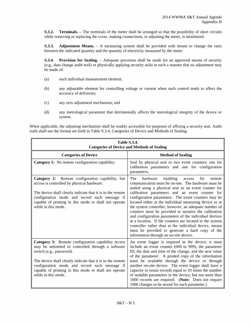
2014 WWMA S&T Annual Agenda Appendix H
S&T – H 5
S.3.2. Terminals. – The terminals of the meter shall be arranged so that the possibility of short circuits while removing or replacing the cover, making connections, or adjusting the meter, is minimized. S.3.3. Adjustment Means. – A measuring system shall be provided with means to change the ratio between the indicated quantity and the quantity of electricity measured by the meter. S.3.4. Provision for Sealing. – Adequate provision shall be made for an approved means of security (e.g., data change audit trail) or physically applying security seals in such a manner that no adjustment may be made of: (a) each individual measurement element; (b) any adjustable element for controlling voltage or current when such control tends to affect the
accuracy of deliveries; (c) any zero adjustment mechanism; and (d) any metrological parameter that detrimentally affects the metrological integrity of the device or
system. When applicable, the adjusting mechanism shall be readily accessible for purposes of affixing a security seal. Audit trails shall use the format set forth in Table S.3.4. Categories of Device and Methods of Sealing.
Table S.3.4. Categories of Device and Methods of Sealing
Categories of Device Method of Sealing
Category 1: No remote configuration capability. Seal by physical seal or two event counters: one for calibration parameters and one for configuration parameters.
Category 2: Remote configuration capability, but access is controlled by physical hardware. The device shall clearly indicate that it is in the remote configuration mode and record such message if capable of printing in this mode or shall not operate while in this mode.
The hardware enabling access for remote communication must be on-site. The hardware must be sealed using a physical seal or an event counter for calibration parameters and an event counter for configuration parameters. The event counters may be located either at the individual measuring device or at the system controller; however, an adequate number of counters must be provided to monitor the calibration and configuration parameters of the individual devices at a location. If the counters are located in the system controller rather than at the individual device, means must be provided to generate a hard copy of the information through an on-site device.
Category 3: Remote configuration capability access may be unlimited or controlled through a software switch (e.g., password). The device shall clearly indicate that it is in the remote configuration mode and record such message if capable of printing in this mode or shall not operate while in this mode.
An event logger is required in the device; it must include an event counter (000 to 999), the parameter ID, the date and time of the change, and the new value of the parameter. A printed copy of the information must be available through the device or through another on-site device. The event logger shall have a capacity to retain records equal to 10 times the number of sealable parameters in the device, but not more than 1000 records are required. (Note: Does not require 1000 changes to be stored for each parameter.)

2014 WWMA S&T Annual Agenda Appendix H
S&T – H 6
S.3.5. [EM] Meter-Control Program. – The meter-control program shall be an integral part of the meter's firmware read-only memory that cannot be changed in its operating environment. This section does not apply to electronic meters that do not utilize a meter-control program.
S.3.6. [EM] Data Storage and Retrieval. Watthour data accumulated and indicated shall be permanent and accessible. (b) Values indicated or stored in memory shall not be affected by electrical, mechanical or temperature variations, radio-frequency interference, power failure, or any other environmental influences to the extent that accuracy is impaired. (c) Memory and/or display shall be recallable for the life of the meter. A replaceable battery shall not be used for this purpose. S.3.7. Temperature Range for Metering Components. - Meters shall be accurate and correct over the temperature range of -20 °C to +50 °C (-4 °F to 122 °F). If the meter or any measuring system components are not capable of meeting these requirements, the temperature range over which the system is capable shall be stated on the NTEP CC, marked on the device, and installations shall be limited to the narrower temperature limits. S.3.8. Zero-Set-Back Interlock, Retail EVSE Devices. A device shall be constructed so that:
(a) when the device is shut-off at the end of a delivery an automatic interlock prevents a subsequent delivery until the indicating element and recording elements, if the device is equipped and activated to record, have been returned to their zero positions; and
(b) it shall not be possible to return the vehicle connector to its starting position unless the
zero-set-back interlock is engaged or becomes engaged. For systems with more than one device supplied by a single measuring element, an effective automatic control in each device prevents product from being delivered until the indicating elements on that device are in a correct zero position; or For systems with more than one connection supplied by a single measuring element, effective automatic means must be provided to prevent product from being delivered until the indicating element(s) corresponding to each connection are in a correct zero position.
S.4. Connections.
S.4.1. Diversion of Measured Electricity. – No means shall be provided by which any measured electricity can be diverted from the measuring device. S.4.2. Directional Control. – If a reversal of energy flow could result in errors that exceed the tolerance for the minimum measured quantity, effective means, automatic in operation to prevent or account for the reversal of flow shall be properly installed in the system. (See N.7. Minimum Measured Quantity)
S.5. Markings. – The following identification and marking requirements are in addition to the requirements of Section 1.10 General Code, paragraph G-S.1. Identification.
S.5.1. Location of Marking Information; EVSE. – The marking information required in General Code, paragraph G S.1. Identification shall appear as follows:
(a) within 60 cm (24 in) to 150 cm (60 in) from ground level;

2014 WWMA S&T Annual Agenda Appendix H
S&T – H 7
(b) either internally and/or externally provided the information is permanent and easily read; and
accessible for inspection; and
(c) on a portion of the device that cannot be readily removed or interchanged (e.g., not on a service access panel).
Note: The use of a key or tool to access internal marking information is permitted for retail electricity-measuring devices. S.5.2. Device Identification and Marking Requirements. – In addition to all the marking requirements of Section 1.10 General Code, paragraph G-S.1. Identification, each device shall have the following information conspicuously, legibly, and indelibly marked on the nameplate or register, if applicable:
(a) the accuracy class of the device as specified by the manufacturer consistent with Table T.4. Accuracy Classes and Load Test Tolerances for Electricity-Measuring Devices;
(b) AC voltage rating;
(c) Test amperes (TA);
(d) Meter class (CL);
(e) Watthour or rotor constant (Kh);
(f) [MM] Register ratio (Rr or Kr) and multiplier (if greater than one)
preceded by “multiply by” or “mult by” or “Kr”;
(g) Frequency rating (Hz);
(h) Number of meter stator(s) or element(s);
(i) Watthour meter or other descriptive term;
(j) [MM] Number of wires (W);
(k) [MM] Form designation (FM);
(l) [EM] Watthour test constant (Kt);
(m) Minimum measured quantity (MMQ).
Instrument transformer-rated meters shall contain the following additional information:
(n) Instrument transformer ratio or transformer model number;
(o) [MM] Primary watthour constant (PKh);
(p) Temperature Limits, if narrower than and within -20°C to +50°C (-4°F to 122°F). S.5.3. Instrument Transformer Identification. – Each instrument transformer that is non-integral with the meter shall have the following conspicuously, legibly, and indelibly marked on a permanent identification label: (a) Manufacturer's name, type designation, and non-repetitive serial number;
2014 WWMA S&T Annual Agenda Appendix H
S&T – H 8
(b) True ratio, primary versus secondary, ampere or voltage values;
(c) Accuracy class;
(d) Burden designation (B);
(e) Basic lightning impulse insulation level (BIL);
(f) Rated Frequency (HZ).
Note: If evident by the method of integration that instrument transformers are not intended to be detachable or replaceable, the required information may be located on the meter.
S.5.3.1. Polarity Marking. – A permanent mark indicating proper installation orientation is required on the instrument transformer when the accuracy of the meter is affected.
S.5.4. Abbreviations and Symbols. – The following abbreviations or symbols may appear on a meter, instrument transformer, or indicator. (a) FM = Form
(b) CL = Class
(c) V = Volts;
(d) Hz = Hertz, Frequency or Cycles Per Second;
(e) TA = Test Amperes;
(f) Kh = Watthour Constant Per Rotor Revolution or Pulse;
(g) PKh = Primary Watthour Constant;
(h) Rr = Register Ratio;
(i) CTR = Current Transformer Ratio;
(j) VTR or PTR = Voltage or Potential Transformer Ratio;
(k) MULT BY = Multiply By;
(l) W = Wire (example: 240V 3W);
(m) Y = WYE Power Supply;
(n) ANSI = American National Standards Institute;
(o) B = Burden;
(p) BIL = Basic Lightning Impulse Insulation Factor;
(q) Kt = [EM] Watthour Test Constant;
(r) AC = Alternating Current (i.e. VAC);
(s) J = Joule;

2014 WWMA S&T Annual Agenda Appendix H
S&T – H 9
(t) MJ = Megajoule;
(u) Wh = Watthour;
(v) kWh = Kilowatt-hour;
(w) ∆ = Delta Power Supply.
S.6. Printer. – When an assembly is equipped with means for printing the measured quantity, the printed information must agree with the indications on the device for the transaction and the printed values shall be clearly defined.
S.6.1. Printed Receipt. – Any delivered, printed quantity shall include a device identification number that uniquely identifies the device from all other devices within the seller’s facility, the time and date, and the name of the seller. This information may be printed by the device or pre-printed on the ticket.
S.7. Totalizers for EVSE Devices. – EVSE devices shall be equipped with a nonresettable totalizer for the quantity delivered through each separate measuring device. S.8. Minimum Measured Quantity. – The minimum measured quantity shall satisfy the conditions of use of the measuring system as follows: Measuring systems shall have a minimum measured quantity not exceeding 3.6 MJ or 1.0 kWh.
N. Notes
N.1. Meter Creep Test. – A meter creep test shall be conducted by applying rated voltage to the meter under test and no load applied. N.2. Meter Starting Load. – A meter starting load test shall be conducted by applying rated voltage and 0.5-ampere load. N.3. [MM] Test Revolutions. – Full and light load tests shall require 8 or more revolutions of the test standard and at least one revolution of the meter under test. N.4. [EM] Meter Test Constant Output Indications. – Full and light load tests shall consist of 8 or more watthour test constant (Kt) output indications of the test standard and at least one watthour test constant (Kt) output indication of the meter under test. Test standards that read out directly in watthours shall meet the watthour equivalent of 8 or more watthour test constant (Kt) output indications. N.5. Meter and System Test Loads.
(a) [MM] Mechanical self-contained meters shall be balanced load tested, and may be single element tested, for meter accuracy at full and light loads.
(b) [MM] Instrument transformer rated systems shall be single element tested, and may be balanced load tested, for system accuracy at full and light loads. Meter testing shall be accomplished by applying the test load to the current transformer(s).
(c) [EM] Instrument transformer(s) rated systems shall be single element tested, for system accuracy at full and light loads. Meter testing shall be accomplished by applying the test load to the instrument transformer(s) with the voltage circuits energized.
(d) The reference voltage phases (A, B, or C) at the meter shall be the same phase as the load. N.6. Test of a Meter System.

2014 WWMA S&T Annual Agenda Appendix H
S&T – H 10
(a) Each meter submitted for test shall be a complete system. For example: a meter body and any necessary
instrument transformer(s), indicator(s), system software, etc., required to make up a complete system. (b) The test load applied for a full load test shall be the marked test amperes (TA) on the nameplate of the
meter under test. (c) The test load applied for a light load test shall be conducted at not less than 10% of the marked (TA) test
amperes on the nameplate of the meter under test. (d) The test load applied for a full load test of a meter for a 0.5 power factor setting shall be the marked (TA)
test amperes of the nameplate of the meter under test. (e) The test load applied for a light load test of a meter for a 0.5 power factor setting shall be conducted at not
less than 20% of the (TA) test amperes of the meter. (f) All tests shall be made at the rated voltage ± 10%.
N.7. Minimum Measured Quantity. – The minimum measured quantity shall be specified by the manufacturer.
N.7.1. Minimum Measured Quantity Test. – The device shall be tested for a delivery equal to the declared minimum measured quantity when the device is likely to be used to make deliveries on the order of the declared minimum measured quantity.
N.8. Repeatability Tests. – Tests for repeatability should include a minimum of three consecutive tests at the same load and be conducted under controlled conditions where variations in factors are reduced to minimize the effect on the results obtained.
T. Tolerances T.1. Tolerances, General.
(a) The tolerances apply equally to errors of underregistration and errors of overregistration.
(b) The tolerances apply to all deliveries measured at any load within the rated measuring range of the device.
(c) Where instrument transformers or other components are used, the provisions of this section shall apply to all metering components.
T.2. Meter Creep Test. T.2.1. [EM] Meter Creep Test. – The meter indicating element shall not change by more than one least significant digit with the voltage circuit(s) energized and current circuit(s) not energized for a duration of one hour using the watthour test constant (Kt) output indications. T.2.2. [MM] Meter Creep Test. – A meter rotor shall rotate no more than one complete revolution in 10 minutes with the meter voltage circuit(s) energized and the current circuit(s) not energized. T.3. Meter Starting Load Test.
T.3.1. [EM] Meter Starting Load Test. – The watthour test constant (Kt) output indication shall
continue to advance when a load of 0.5 amperes is applied. T.3.2. [MM] Meter Starting Load Test. – The meter rotor shall rotate continuously when a load of 0.5
amperes is applied. T.4. Load Test Tolerances. – The tolerances for electricity-measuring device load tests are listed in Table T.2. Accuracy Classes and Tolerances for Electricity-Measuring Devices. (Proposed tolerance values are based on ANSI C12.1 Code for Electricity Metering Section 5 Standards for In-Service Performance paragraph 5.1.2.2 Acceptable Performance for Maintenance Tolerances and on ANSI C12.20 Electricity Meters-0.2 and 0.5 Accuracy Classes

2014 WWMA S&T Annual Agenda Appendix H
S&T – H 11
Section 5 Acceptable Performance of New Types of Electricity Metering Devices and Associated Equipment paragraph 5.5.4.3 Test No. 3: Load Performance for Acceptance Tolerances.)
Table T.4. Accuracy Classes and Load Test Tolerances for Electricity-Measuring Devices
Accuracy Class (ANSI C12.20 designation)
Application or Commodity Being Measured
Acceptance Tolerance
Maintenance Tolerance
0.2 Electricity as vehicle fuel 0.2 % 2.0 %
0.5 Electricity as vehicle fuel 0.5 % 2.0 %
All Others Electricity as vehicle fuel 1.0 % 2.0 %
Instrument Transformers Not Integral to the Meter
0.3 or superior Electricity as vehicle fuel 0.3 % 2.0 % as part of system
T.4.1. Tolerance Values. – Maintenance and acceptance tolerances for electric watthour meters shall be as shown in Table T.4. for full and light load tests of Accuracy Class 0.2 and 0.5 meters. For all other Accuracy Class meters tolerances shall be as follows: (a) Maintenance tolerance shall be 2 percent for full and light loads.
(b) Acceptance tolerance shall be 1 percent for full and light loads.
T.4.2. Power Factor Tests. – Power factor tests shall be conducted at 0.5 power factor setting: (a) Maintenance tolerance shall be 2 percent for full and light loads.
(b) Acceptance tolerance shall be 1 percent for full and light loads. NOTE: 0.5 power factor light load tests shall be conducted at 20 percent of the Test Amperes (TA).
T.5. Repeatability. – When multiple tests are conducted at the same load condition, the range of the load test results shall not exceed 25% of the absolute value of the maintenance tolerance and the results of each test shall be within the applicable tolerance. (Indiana Code 170 IAC 4-1-8). T.6. Instrument Transformer Accuracy Class. – An instrument transformer that is not an integral part of the meter and is used for revenue metering shall be rated 0.3 accuracy class or more accurate for the burden of a particular meter type. If a meter system requires an instrument transformer more accurate than 0.3 accuracy class, the limitations shall be stated on the meter. T.7. Tolerance Application in Type Evaluation Examinations for Devices. – For type evaluation examinations, the acceptance tolerance values shall apply under the following conditions:
(a) at any temperature, voltage, load, and power factor within the operating range of the device, and
(b) regardless of the influence factors in effect at the time of the conduct of the examination, and

2014 WWMA S&T Annual Agenda Appendix H
S&T – H 12
(c) for all quantities greater than the minimum measured quantity.
UR. User Requirements UR.1. Selection Requirements.
UR.1.1. Meter Class (CL). – The marked CL shall equal or exceed the total capacity in amperes of the EVSE or the thermal overload protectors of the tenant. UR.1.2. Suitability of Equipment. – A meter shall be suitable for use on its electrical system. A 3-wire two-phase load which is connected to a 120-208 volt network service shall be metered by a two-stator or two-element meter. A meter shall accurately measure all loads 5 percent or greater of the electric service capacity of the tenant. Service capacity shall be determined by the master thermal overload protectors to the tenants’ service or by the rated capacity of an electric cord and its connector used to provide power from the service panel to the tenant. UR.1.3. Instrument Transformer Ratio. – The instrument transformer shall be correctly matched to the meter indicator and multiplier. UR.1.4. Computing-Type Device; Retail EVSE Device. – A device used to charge electric vehicles shall be of the computing type and shall indicate the electrical energy, the unit price, and the total price of each delivery. UR.1.5. Connection Line-Length. – The impedance of the connection line on a retail EVSE device shall not result in losses in excess of the tolerance. The length of the connection line:
(a) shall not exceed 4.6 m (15 ft) unless it can be demonstrated that a longer line is essential to permit deliveries to be made to receiving vehicles;
(b) shall be measured from its connection to the EVSE to the inlet of the vehicle connector; and
(c) shall be measured with the connection line fully extended if it is coiled or otherwise retained or
connected inside a housing. An unnecessarily remote location of a device shall not be accepted as justification for an abnormally long connection line.
UR.2. Installation Requirements. UR.2.1. Manufacturer’s Instructions. – A device shall be installed in accordance with the manufacturer’s instructions, and the installation shall be sufficiently secure and rigid to maintain this condition.
UR.2.2. Load Range. – A device shall be installed so that the current and voltage will not exceed the rated maximum values over which the meter class designation is designed to operate continuously within the specified accuracy. Means to limit current and/or voltage shall be incorporated in the installation if necessary. UR.2.3. Regulation Conflicts and Permit Compliance. – If any provision of this section (UR.2. Installation Requirements) is less stringent than that required of a similar installation by the serving utility, the installation shall be in accordance with those requirements of the serving utility. The installer of any new EVSE or electric watthour submeter service shall obtain all necessary permits and shall conform to all applicable regulatory utility commission’s or commissioner’s requirements.

2014 WWMA S&T Annual Agenda Appendix H
S&T – H 13
UR.2.4. Submeter Installation Requirements.
UR.2.4.1. Certification by Serving Utility or Utilities Commission. – It is the responsibility of the owner of a submeter system to obtain written certification for each submetered service connection from the serving utility or from a person designated as qualified by either the serving utility or by the Utilities Commission (UC).
(a) The required certification shall identify the address, space, or number, of the premise served by the
submeter connection; be signed by an authorized serving utility representative or by a designee; and shall clearly state:
(b) the installation meets all serving utility installation and accessibility requirements for similar installations served directly by the serving utility,
(c) the installation is on a tariff schedule that qualifies for submeter use,
(d) the billing format, rates, and charges conform to all applicable serving utility tariff rules,
(e) the date of such determination, and
(f) if performed by a designee, the designee’s name and title, and the name and title of the serving utility company or Public Utilities Commission representative authorizing the designee to make the determination.
The certification shall be provided prior to a submeter being used for commercial purposes.
UR.2.4.2. Submeter Test Facilities. – All submeters shall be provided with the same test facilities required of a similar meter by the serving utility. UR.2.4.3. [MM] Test Blocks. – All three-phase self-contained submeter installations shall be equipped with test blocks, which are approved by the serving utility, for safe meter testing. UR.2.4.4. [MM] Test Switches. – Submeter installations that are equipped with current or potential transformers, or both, shall have test switches installed, which are approved by the serving utility, for safe meter testing. UR.2.4.5. [MM] Circuit Closing Devices. – All self-contained submeter installations that cannot accept a short interruption of the electrical service, for the purpose of testing the meter, shall be equipped with a manual circuit closing device as approved by the serving utility. Automatic circuit closing devices shall not be used on any submeter installation. UR.2.4.6. Metered Circuits (Submeter Load Service). – All electricity used by a tenant shall be taken exclusively from the load service of the tenant's meter. This service and its associated meter shall accurately measure the tenant's load and be capable of being used only at the discretion of the tenant. UR.2.4.7. Unmetered Circuits (Submeter Line Service). – The tenant’s electric circuit shall not be taken from the line terminals of the meter, meter socket, or line service. The owner of the submeter system may utilize this service. UR.2.4.8. Dedicated Tenant Submeter Service. – A meter shall serve only the space, lot, building, room, suite, stall, slip, or premise occupied by the tenant. UR.2.4.9. Submetered Tenant Premise Identification. – Tenant premise identification shall be clearly and permanently shown on or at the submeter, and on all separate components of a meter system, including, but not limited to, instrument transformer(s), modem(s), and transmitter(s) if equipped. Remote

2014 WWMA S&T Annual Agenda Appendix H
S&T – H 14
indications and all printed indications shall be readily identifiable and readily associated with the tenant’s premise. Printed indications shall also include time and date information.
UR.3. Use of Device.
UR.3.1. Unit Price for Retail EVSE Devices. – The unit price at which the device is set to compute shall be conspicuously displayed or posted on the face of a retail EVSE device used in direct sale. UR.3.2. Return of Indicating and Recording Elements to Zero. – The primary indicating elements (visual) and the primary recording elements shall be returned to zero immediately before each delivery. UR.3.3. Printed Ticket. – The total price, the total quantity of the delivery, and the price per unit shall be printed on any ticket issued by a device of the computing type and containing any one of these values. UR.3.4. Steps After Charging. – After delivery to a customer from a retail device:
(a) the device shall be shut-off at the end of a charge, through an automatic interlock that prevents subsequent charging until the indicating elements and recording elements, if the device is equipped and activated to record, have been returned to their zero positions; and
(b) the vehicle connector shall not be returned to its starting position unless the zero set-back interlock
is engaged or becomes engaged by the act of disconnecting from the vehicle or the act of returning the connector to the starting position.
UR.3.5. Submeter Required. – When a tenant is not directly served by the serving utility, and charges for electric energy are not included in the fixed periodic rent charges, a dedicated electric watt-hour submeter that measures only the energy used at the discretion of the tenant shall be used.
Appendix D. Definitions
The specific code to which the definition applies is shown in [brackets] at the end of the definition. Definitions for the General Code [1.10] apply to all codes in Handbook 44.
A accuracy class, instrument transformers. – A performance specification for instrument transformers which expresses the maximum deviation from the true value of a measured quantity. (Instrument Transformer Accuracy Class) example: a 0.2 accuracy class transformer would be more accurate than a 0.3 accuracy class transformer.[3.XX] active (real) power. – The component of electric power that performs work, typically measured in kilowatts (kW) or megawatts (MW). Also known as "real power." The terms "active" or "real” power are used to modify the base term "power" to differentiate it from reactive and apparent power. The active power (Pac) or real power measured by a meter, is the product of voltage (E) times current (I) times the cosine of the angle by which the current lags the voltage (cos φ) or power factor (pf). Pac = (E) (I) (pf) = (E) (I) (cos φ) where φ is the phase angle of the lag.[3.XX] alternating current (AC). – An electric current that reverses direction in a circuit at regular intervals.[3.XX] ampere. – The practical unit of electric current. It is the quantity of current caused to flow by a potential difference of one volt through a resistance of one ohm. One ampere is equal to the flow of one coulomb of charge per second. One coulomb is the unit of electric charge equal in magnitude to the charge of 6.24 x 10¹⁸ electrons.[3.XX] apparent power. – The product of the RMS current (I) and the RMS voltage (E) in a circuit.[3.XX] audit trail. – An electronic count and/or information record of the changes to the values of the calibration or configuration parameters of a device.[1.10, 2.20, 2.21, 2.24, 3.30, 3.37, 3.39, 3.XX, 5.56(a)]
2014 WWMA S&T Annual Agenda Appendix H
S&T – H 15
(Added 1993)
B balanced load. – Balanced load is used to indicate equal currents in all phases and relatively equal voltages between phases and between each phase and neutral (if one exists); with approximately equal watts in each phase of the load.[3.XX] basic lightning impulse insulation level (BIL). – A specific insulation level expressed in kilovolts of the crest value of a standard lightning impulse. (Example: BIL = 10 Kv)[3.XX] burden (B). – The impedance of the circuit connected to the instrument transformer's secondary winding. (Example: B = 21 Ohms Max.)[3.XX]
C calibration parameter. – Any adjustable parameter that can affect measurement or performance accuracy and, due to its nature, needs to be updated on an ongoing basis to maintain device accuracy, e.g., span adjustments, linearization factors, and coarse zero adjustments.[2.20, 2.21, 2.24, 3.30, 3.37, 3.39, 3.XX, 5.56(a)] (Added 1993) central location. – A laboratory or meter shop used for the testing of meters to measure in-service accuracy.[3.XX] certified meter type. – A metering device which is tested and certified to meet the certification testing as specified in the ANSI C12 standard for a specific meter type. It shall include any optional circuit boards, devices, or modules enclosed within the meter cover as a part of this certified meter type.[3.XX] configuration parameter. – Any adjustable or selectable parameter for a device feature that can affect the accuracy of a transaction or can significantly increase the potential for fraudulent use of the device and, due to its nature, needs to be updated only during device installation or upon replacement of a component, e.g., division value (increment), sensor range, and units of measurement.[2.20, 2.21, 2.24, 3.30, 3.37, 3.XX, 5.56(a)] (Added 1993) connection line impedance. – The impedance of the circuit used to convey energy sold from a fueling device to the storage of an electric vehicle.[3.XX] creep. – A continuous apparent measurement of energy indicated by a meter with operating voltage applied and no power consumed (load terminals open circuited) .[3.XX] current. – The rate of the flow of electrical charge past any one point in a circuit. The unit of measurement is amperes or coulombs per second.[3.XX]
E
electric vehicle, plug-in. – A vehicle that employs electrical energy as a primary or secondary mode of propulsion. Plug-in electric vehicles may be all-electric vehicles (EV’s) or plug-in hybrid electric vehicles (PHEV’s). All-electric vehicles are powered by an electric motor and battery at all times. All-electric vehicles may also be called battery-electric vehicles (BEV’s). Plug-in hybrid electric vehicles employ both an electric motor and an internal combustion engine that consumes either conventional or alternative fuel or a fuel cell. In a parallel type hybrid-electric vehicle, either the electric motor or the engine may propel the vehicle. In a series type hybrid-electric vehicle, the engine or fuel cell generates electricity that is then used by the electric motor to propel the vehicle. EV’s, BEV’s, and PHEV’s are capable of receiving and storing electricity via connection to an external electrical supply. Not all hybrid-electric vehicles are of the plug-in type. Hybrid-electric vehicles that do not have the capability to receive electrical energy from an external supply (HEV’s) generate electrical energy onboard with the internal combustion engine, regenerative braking, or both.[3.XX]
2014 WWMA S&T Annual Agenda Appendix H
S&T – H 16
electric vehicle supply equipment (EVSE). – The conductors, including the ungrounded, grounded, and equipment grounding conductors; the electric vehicle connectors; attachment plugs; and all other fittings, devices, power outlets, or apparatuses installed specifically for the purpose of measuring, delivering, and computing the price of electrical energy delivered to the electric vehicle.[3.XX] electricity sold as vehicle fuel. – Electrical energy transferred to and/or stored onboard an electric vehicle primarily for the purpose of propulsion.[3.XX] electricity meter. – A device that measures and registers the integral of an electrical quantity with respect to time.[3.XX] electronic meter [EM]. – An electric (solid state) watthour meter that does not have a rotor.[3.XX] element (stator). – A combination of a voltage-sensing unit and a current-sensing unit, which provides an output proportional to the quantities measured.[3.XX] energy. – The integral of active power with respect to time.[3.XX] energy flow. – The flow of energy between line and load terminals (conductors) of an electricity meter. Flow from the line to the load terminals is considered energy delivered. Energy flowing in the opposite direction (i.e., from the load to line terminals) is considered as energy received.[3.XX] equipment, commercial. – Weights, measures, and weighing and measuring devices, instruments, elements, and systems or portion thereof, used or employed in establishing the measurement or in computing any basic charge or payment for services rendered on the basis of weight or measure. As used in this definition, measurement includes the determination of size, quantity, value, extent, area, composition (limited to meat and poultry), constituent value (for grain), or measurement of quantities, things, produce, or articles for distribution or consumption, purchased, offered, or submitted for sale, hire, or award.[1.10, 2.20, 2.21, 2.22, 2.24, 3.30, 3.31, 3.32, 3.33, 3.34, 3.35, 3.38, 3.XX, 4.40, 5.51, 5.56.(a), 5.56.(b), 5.57, 5.58, 5.59] (Added 2008) equipment level. – A designation given to different categories of EVSE’s that conveys the general speed with which charging will occur.[3.XX] event counter. – A nonresettable counter that increments once each time the mode that permits changes to sealable parameters is entered and one or more changes are made to sealable calibration or configuration parameters of a device.[2.20, 2.21, 3.30, 3.37, 3.39, 3.XX, 5.54, 5.56(a), 5.56(b), 5.57] (Added 1993) event logger. – A form of audit trail containing a series of records where each record contains the number from the event counter corresponding to the change to a sealable parameter, the identification of the parameter that was changed, the time and date when the parameter was changed, and the new value of the parameter.[2.20, 2.21, 3.30, 3.37, 3.39, 3.XX, 5.54, 5.56(a), 5.56(b), 5.57] (Added 1993)
F face. – That portion of a computing-type pump or dispenser which displays the actual computation of price per unit, delivered quantity, and total sale price. In the case of some electronic displays, this may not be an integral part of the pump or dispenser.[3.30, 3.XX] (Added 1987) fixed service. – Service that continuously provides the nominal power that is possible with the equipment as it is installed.[3.XX]

2014 WWMA S&T Annual Agenda Appendix H
S&T – H 17
form designation (FM). – [MM] An alphanumeric designation denoting the circuit arrangement for which the meter is applicable and its specific terminal arrangement. The same designation is applicable to equivalent meters for all manufacturers. (Example: FM 2S)[3.XX]
H hertz (Hz). – Frequency or cycles per second. One cycle of an alternating current or voltage is one complete set of positive and negative values of the current or voltage.[3.XX]
I instrument transformer. – A transformer that reproduces in its secondary circuit, in a definite and known proportion, the voltage, or current of its primary circuit, with the phase relation preserved. Sometimes these devices may be referred to as VTs (Voltage Transformers) or CTs (Current Transformers).[3.XX] instrument transformer-rated meter. – A metering system with terminals arranged for connection to the secondary windings of external instrument transformers.[3.XX] instrument transformer ratio. – The stated ratio of the primary circuit current or voltage compared to the secondary circuit current or voltage. (Example: CTR = 200 : 0.1)[3.XX]
J megajoule (MJ). – An SI unit of energy equal to 1,000,000 joules.[3.XX]
K kilowatt (kW). – A unit of power equal to 1,000 watts.[3.XX] kilowatt-hour (kWh). – A unit of energy equal to 1,000 watthours.[3.XX]
L line service. – The service terminals or conductors connecting the meter to the power source.[3.XX] load service. – The service terminals or conductors connecting the meter to the electrical load (e.g., vehicle, tenant, etc.)[3.XX] load, full. – A test condition with rated voltage, current at 100% of test amps level, and power factor of 1.0.[3.XX] load, light. – A test condition with rated voltage, current at 10% of test amps level, and power factor of 1.0.[3.XX].
M master meter, electric. – An electric watthour meter owned, maintained, and used for commercial billing purposes by the serving utility. All the electric energy served to a submetered service system is recorded by the master meter.[3.XX] mechanical meter [MM]. – A watthour meter with a rotor.[3.XX] meter class designation (CL). – The manufacturer's designated maximum amperes a meter can measure continuously without damage or exceeding limits of accuracy. (Example: CL 200)[3.XX] meter, electricity. – An electric watthour meter.[3.XX]

2014 WWMA S&T Annual Agenda Appendix H
S&T – H 18
metrological components. – Elements or features of a measurement device or system that perform the measurement process or that may affect the final quantity determination or resulting price determinations. This includes accessories that can affect the validity of transactions based upon the measurement process. The measurement process includes determination of quantities; the transmission, processing, storage, or other corrections or adjustments of measurement data or values; and the indication or recording of measurement values or other derived values such as price or worth or charges.[3.XX]
N nominal power. – Refers to the “intended” or “named” or “stated” as opposed to “actual” rate of transfer of electrical energy (i.e., power).[3.XX] nonresettable totalizer. – An element interfaced with the measuring or weighing element that indicates the cumulative registration of the measured quantity with no means to return to zero.[3.30, 3.37, 3.39, 3.XX]
O ohm. – The practical unit of electric resistance that allows one ampere of current to flow when the impressed potential is one volt.[3.XX]
P percent registration. – Percent registration is calculated as follows:
100xTANDARDSbymeasuredWhMETERbymeasuredWhgistrationRePercent =
[3.XX]
percent error. – Percent Error = Percent Registration – 100. A meter is said to be “slow” that has percent registration below 100% and negative percent error.[3.XX]. point-of-sale system. – An assembly of elements including a weighing or measuring element, an indicating element, and a recording element (and may also be equipped with a “scanner”) used to complete a direct sales transaction.[2.20, 3.30, 3.32, 3.37, 3.39, 3.XX] (Added 1986) (Amended 1997) power factor. – The ratio of the active power to the apparent power in an AC circuit. The power factor is a number between 0 and 1 that is equal to 1 when the voltage and current are in phase (load is entirely resistive).[3.XX] primary watthour constant (PKh) [MM]. – The meter watthour constant per revolution or pulse (Kh) multiplied by the product of the current and/or voltage transformer ratio(s): PKh = Kh (Current Transformer Ratio X Voltage Transformer Ratio) [3.XX]
R reactive power. – For sinusoidal quantities in a two-wire circuit, reactive power is the product of the voltage, the current, and the sine of the phase angle between them, using the current as the reference.[3.XX] register ratio (Rr) [MM]. – The number of revolutions of the gear meshing with the worm or pinion on the rotor shaft per complete rotation of the fastest (most sensitive) wheel or dial pointer.[3.XX]

2014 WWMA S&T Annual Agenda Appendix H
S&T – H 19
remote configuration capability. – The ability to adjust a weighing or measuring device or change its sealable parameters from or through some other device that is not itself necessary to the operation of the weighing or measuring device or is not a permanent part of that device.[2.20, 2.21, 2.24, 3.30, 3.37, 3.39, 3.XX, 5.56(a)] (Added 1993) retail device. – A measuring device primarily used to measure product for the purpose of sale to the end user.[3.30, 3.32, 3.37, 3.39, 3.XX] (Amended 1987 and 2004) revolution equivalent. – The number of watthours represented by one increment (pulse period) of serial data.[3.XX] root mean square (RMS). – The mathematical convention used to describe the average quantity of a property (such as current) that is varying as a sine wave.[3.XX]
S serving utility. – The utility distribution company that owns the master meter and sells electric energy to the owner of a submeter system.[3.XX] side. – That portion of a pump or dispenser which faces the consumer during the normal delivery of product.[3.30, 3.XX] (Added 1987) starting load. – The minimum load above which the device will indicate energy flow continuously.[3.XX] stator [MM]. – The unit which provides the driving torque in a watthour meter. It contains a voltage coil, one or more current coils, and the necessary steel to provide the required magnetic paths.[3.XX] submeter. – A meter furnished, owned, installed, and maintained by the customer who is served through a utility owned master meter.[3.XX]
T tenant. – The person or persons served electric energy from a submetered service system.[3.XX] test accuracy – in-service. – The device accuracy determined by a test made during the period that the meter is in service. It may be made on the customer’s premises without removing the meter from its mounting, or by removing the meter for testing either on the premises or in a laboratory or meter shop.[3.XX] test amperes (TA). – The full load current (amperage) specified by the device manufacturer for testing and calibration adjustment. (Example: TA 30)[3.XX] test block. – Device that facilitates safe meter testing by disconnecting the meter from the circuit without interrupting the service to the tenant.[3.XX] thermal overload protector. – A circuit breaker or fuse that automatically limits the maximum current in a circuit.[3.XX]
U unit price. – The price at which the product is being sold and expressed in whole units of measurement.[1.10, 3.30, 3.XX] (Added 1992)
V

2014 WWMA S&T Annual Agenda Appendix H
S&T – H 20
variable service. – Service that may be controlled resulting in periods of reduced, and/or interrupted transfer of electrical energy.[3.XX] volt. – The practical unit of electromotive force. One volt will cause one ampere to flow when impressed across a resistance of one ohm.[3.XX] voltage transformer. – A device that provides a secondary voltage that is a precise fraction of the primary voltage.[3.XX]
W watt. – The practical unit of electric power. In an alternating-current circuit (AC), the power in watts is volts times amperes multiplied by the circuit power factor.[3.XX] watthour (Wh). – The practical unit of electric energy, which is expended in one hour when the average power consumed during the hour is one watt.[3.XX] watthour meter. – An electricity metering system comprised of components functioning together that measures and registers the integral, with respect to time, of the active or real power of the circuit in which it is connected. This power integral is the energy delivered to the circuit during the interval over which the integration extends. The unit in which this integral is measured is usually the kilowatt-hour.[3.XX]. watthour meter – field standard. – A portable meter that is traceable to NIST and is used as a standard meter to test meters in commercial applications. This meter is also known as a portable standard or working standard.[3.XX] watthour meter – self-contained. – A meter in which the terminals are arranged for connection to the circuit being measured without using external instrument transformers.[3.XX] watthour meter constant (Kh). – The expression of the relationship between the energy applied to the meter and one rotor revolution, or output indication, expressed as watthours per revolution or, watthours per output indication.[3.XX] watthour meter – test constant (Kt) [EM]. – The expression of the relationship between the energy applied to the meter system and corresponding occurrence of one test output indication expressed as watthours per test output indication.[3.XX]