writing a first basic program. · fosc = intio67 ' internal oscillator, port function on ra6/7...
TRANSCRIPT
PIC Projects – Chapter 2 Getting everything connected and writing a first BASIC program.
1 V1.2 - © Joe’s Hobby Electronics, 2011, 2012
Writing a first BASIC program.
I’m not going to cover the installation of the AMICUS18 BASIC compiler as it’s already covered
by the supplier. You can download AMICUS18 from here: http://www.myamicus.co.uk/ which is
around 50 Mb in size. You will also need to download a version of Microchips MPLAB which is
an even larger download unfortunately. Just follow the AMICUS instructions & links carefully
and you will be instructed what to download and install.
For information, I run AMICUS18 on three different computers; my main work-horse PC which
is some top of the range beast with Windows 7-64 bit, the PC on my work bench that is at the
other end of the scale and is a very old slow thing with Windows XP, and also my 1.5GHz
Laptop, also running XP, and AMICUS runs perfectly on all of these.
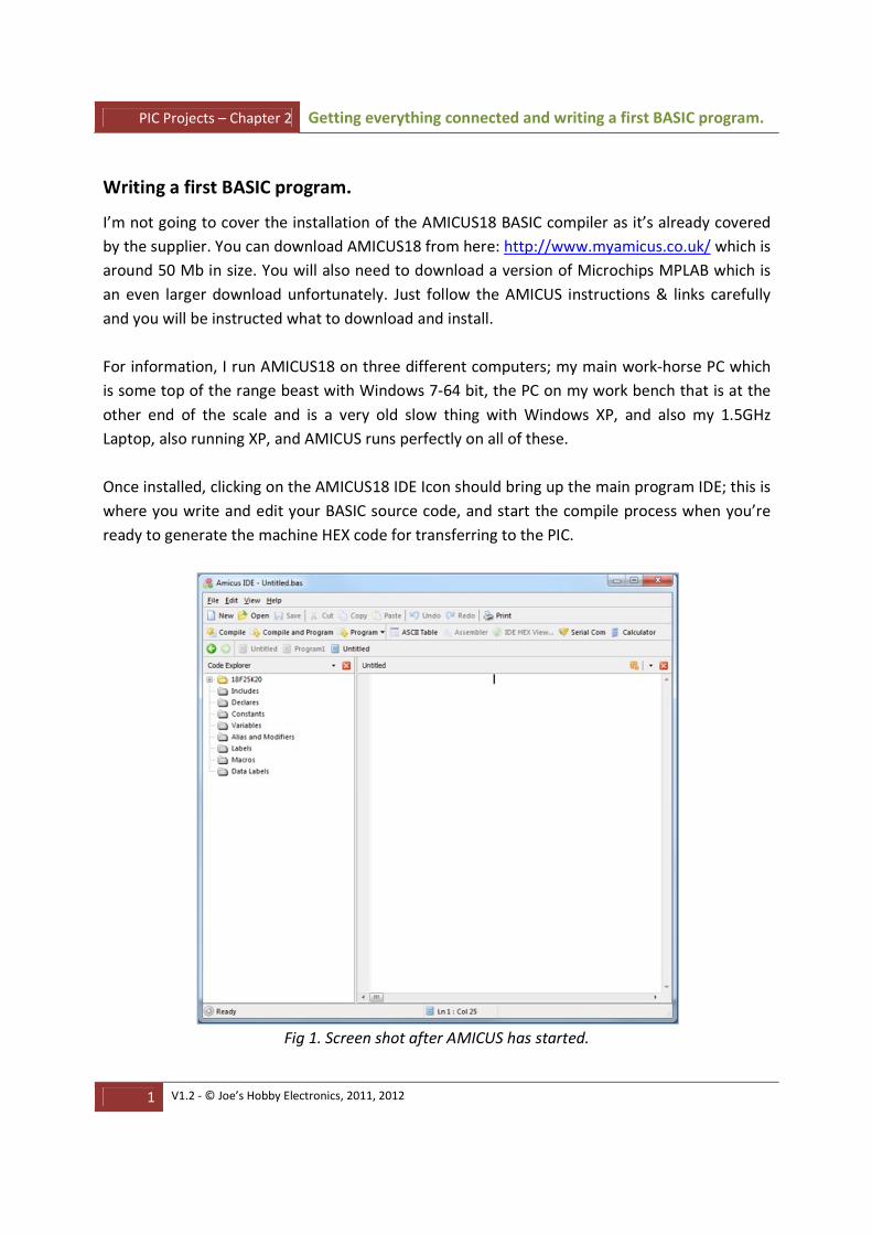
Once installed, clicking on the AMICUS18 IDE Icon should bring up the main program IDE; this is
where you write and edit your BASIC source code, and start the compile process when you’re
ready to generate the machine HEX code for transferring to the PIC.
Fig 1. Screen shot after AMICUS has started.

PIC Projects – Chapter 2 Getting everything connected and writing a first BASIC program.
2 V1.2 - © Joe’s Hobby Electronics, 2011, 2012
The AMICUS IDE is divided into four main parts.
At the top, you have the menus and tool bars. Down the left is the Code Explorer window. As
you start to write your program, variables, labels and other definitions will appear in here.
There is a bottom section where status information is shown and to the right is the large main
code entry window where you enter your program source text.
The first BASIC program we are going to write is the PIC equivalent of the infamous “Hello
World” program that is often written as the first program on many computers. Since a PIC
doesn’t have a VDU or printer, we will have to be content with flashing a LED instead.
'-------------------------------------------------------------------------------
' Program to flash a LED
' Prg1-LEDFlash.bas
' PIC18F25K22 @ 16MHz
' (C) Joe Farr, 2012
'-------------------------------------------------------------------------------
' Version Details
' 1.0 08/01/12 Initial version
'-------------------------------------------------------------------------------
' I/O Assignments:
' C4 - Connects to LED Anode
'-------------------------------------------------------------------------------
'-- Configure the PIC
Device 18F25K22 ' We need to configure the PIC's internal clock generator and set some other options OSCCON = %01110000 ' Select internal clock at 16MHz - Also set SCS=00 (Primary Clock)
OSCTUNE.6 = 1 ' Enable the PLL
Config_Start FOSC = INTIO67 ' Internal oscillator, port function on RA6/7 PLLCFG = On ' Internal clock will be multiplied by 4 PRICLKEN = Off ' Primary clock disabled WDTEN = Off ' Watch dog timer is always disabled. SWDTEN has no effect. Config_End Xtal 64 ' Internal clock running at 16MHz, and we have the x4 PLL on.. ' so 16MHz x 4 = 64MHz
All_Digital True ' All I/O ports are for digital use
'-- Configure I/O ports and pins here
Output PORTC.4 ' Tell the compiler that PORTC.4 is an output
'-- Start ot main program
FlashAgain:
High PORTC.4 ' Set PORTC.4 = Logic HIGH = LED On DelayMS 250 ' Delay for 250ms (1/4 second) Low PORTC.4 ' Set PORTC.4 = Logic LOW = LED Off DelayMS 250 ' Delay for 250ms (1/4 second)
DelayMS 250 GoTo FlashAgain ' Jump back to the start of the routine, and start again
Fig 2. BASIC source code listing of our LED Flash program.

PIC Projects – Chapter 2 Getting everything connected and writing a first BASIC program.
3 V1.2 - © Joe’s Hobby Electronics, 2011, 2012
A couple of things to take note off before you start typing things. The compiler ignores blank
lines, so feel free to add as many as you like. Normally they are inserted to make the source
text easier to read; it’s a bit like adding paragraphs to your text. Second, anything after a single
quote is classed as a comment (text turns blue), and will also be ignored by the compiler.
When I say the compiler will ignore things, I mean exactly that. Blank lines and comments do
NOT take any space in your end program so you can add as many as you like, and I advise you
to add a lot. If you write a program today without any comments and come back to it in three
months you will have a hard time trying to remember what it’s supposed to be doing. If you feel
the need to comment every line, then do it. Better too many comments than not enough, but
be warned. As you change or debug your program, don’t forget to update your comments.
Comments that are incorrect are worse than no comments at all!
I always add a standard comment block at the top of every program. A brief description of what
the program does, its name, and when I wrote it. Then I add a revision list. I don’t update this
for every tiny change until I’ve decided that the program is complete. If I then come back to the
program later on and make some revisions, I add a new entry briefly explaining what was done
and why. The last section contains a brief one liner for each I/O pin that my program will use on
the PIC, and what it’s used for.
I’ll now go through each line of this program and explain what everything does. You will find
that over time, most of your programs start basically the same way and you will probably just
end up cutting and pasting the text from a previous program and then “hacking” it around.
Device 18F25K22
This tells the compiler what PIC we are going to be using. PICs all contain different amounts of
RAM, EEPROM, program memory and peripheral devices. Telling the compiler what PIC we are
going to be using, allows it to make decisions on how to accomplish certain tasks, and it can
warn you if you make a possible silly mistake.
' We need to configure the PIC's internal clock generator and set some other options
OSCCON = %01110000 ' Select internal clock at 16MHz - Also set SCS=00 (Primary Clock)
OSCTUNE.6 = 1 ' Enable the PLL
Config_Start FOSC = INTIO67 ' Internal oscillator, port function on RA6/7 PLLCFG = On ' Internal clock will be multiplied by 4 PRICLKEN = Off ' Primary clock disabled WDTEN = Off ' Watch dog timer is always disabled. SWDTEN has no effect. Config_End Xtal 64 ' Internal clock running at 16MHz, and we have the x4 PLL on.. ' so 16MHz x 4 = 64MHz

PIC Projects – Chapter 2 Getting everything connected and writing a first BASIC program.
4 V1.2 - © Joe’s Hobby Electronics, 2011, 2012
This block of code is responsible for updating the PICs internal configuration registers as
required, and this is where you really need to check out the datasheet for the PIC in question.
The datasheet indicates that this PIC has fourteen CONFIG registers, and their contents are
directly affected by the entries contained between the “Config_Start” and “Config_End”
directives within the program.
For our test circuit, I wanted it to be as simple as possible, so decided that I would use the PIC’s
internal oscillator clock as opposed to using an external crystal and load capacitors.
Fig 3. PIC’s internal oscillator block diagram and configuration.
The datasheet has 19+ pages devoted to just the PICs clock generation and support circuitry.
There are also additional references and snippets of information throughout the rest of the
datasheet. The path highlighted in purple shows how we need to configure the PICs pathways

PIC Projects – Chapter 2 Getting everything connected and writing a first BASIC program.
5 V1.2 - © Joe’s Hobby Electronics, 2011, 2012
to support the required clock option. Think of it like a giant train track, and you have to set all
the points correctly. Each “MUX” or multiplexer, is the set of points and these have to be
configured so that the signal can follow the required path.
OSCCON = %01110000 ' Select internal clock at 16MHz - Also set SCS=00 (Primary Clock)
Here we are setting the contents of the 8-bit register OSCCON with a binary value. Binary values
are read from right to left, so %01110000 actually equals 0+64+32+16+0+0+0+0 or 112 decimal.
It often makes more sense to work in binary when manipulating the PICs registers.
Look at the datasheet to see what each bit in OSCCON is for.
OSCTUNE.6 = 1 ' Enable the PLL
Here we are setting just bit 6 in the OSCTUNE register to enable the Phase Locked Loop (PLL).
This will multiply our clock by x 4.
Config_Start FOSC = INTIO67 ' Internal oscillator, port function on RA6/7 PLLCFG = On ' Internal clock will be multiplied by 4 PRICLKEN = Off ' Primary clock disabled WDTEN = Off ' Watch dog timer is always disabled. SWDTEN has no effect. Config_End
This block is updating entries in the PICs configuration registers. These registers,
unimaginatively called CONFIGnH and CONFIGnL where n is a number, are each 8 bits wide.
A check of the datasheet shows that FOSC is actually located in bits 0 to 3 of CONFIG1H, and
then goes on to explain exactly what all the different values mean.
WDTEN = Off ' Watch dog timer is always disabled. SWDTEN has no effect.
Here we just turn off the PIC’s inbuilt watchdog timer.
Xtal 64
This is an important directive and is used by the compiler to adjust any timing loops
automatically. The built in delays and communication routines all require accurate timing and
it’s important to get this value correct.
Remember that we set the internal clock source to run at 16 MHz (OSCON register) AND we
enabled the PLL (OSCTUNE register) which multiplies our clock by 4.
16 MHz x 4 = 64 MHz.
The same would be true if we had configured the PIC to use an external 16 MHz crystal.
All_Digital True
This tells the compiler to set all the PIC’s internal configuration bits required, to make sure that
all the pins are set for digital use. There are a lot of them. Check the datasheet.
PIC Projects – Chapter 2 Getting everything connected and writing a first BASIC program.
6 V1.2 - © Joe’s Hobby Electronics, 2011, 2012
Output PORTC.4
Here we tell the compiler that PORTC, bit 4 will be used as an output.
FlashAgain:
This is a label and actually doesn’t generate any code. It’s a book mark for the compiler to use
later on. If you add these to a program and then don’t use them, they won’t use any extra
space and can be left in place. It is good programming practice to remove labels and code that
aren’t required though.
High PORTC.4
Tells the compiler to write a logic “1” to PORTC, bit 4 which in our circuit, will turn the LED on.
DelayMS 250
The compiler will insert a loop into the generated machine code file that will force the PIC to
waste 250ms. The PIC will “appear” to freeze for 250ms, however, it’s actually franticly running
around a loop, wasting time – this can be useful for many reasons and we will look at why much
later on when we explore Interrupts.
You should now be able to guess what the next two lines, (LOW PORTC.4 and DelayMs 250) will
do.
GoTo FlashAgain
Tells the compiler to force the PIC to start executing code from a point in the program where
“FlashAgain” is located.
That’s it. When the PIC is programmed with this program, and a suitable LED etc is attached, it
will flash on and off every ¼ second until you stop it.
Enter code from Fig 2 into the AMICUS IDE. To save time, you can skip the comments if you
want.
Once you’ve entered the text it’s always sensible to save your work.
Pressing the “Save” button from the toolbar will force the IDE to ask you where you would like
to store your file. You can opt to store the files at the default location or any other place you
desire. Do NOT place them at the root of a drive. When the compile process starts it creates all
sorts of additional files that soon clutter the place up.
Give your file a name, Program1 for example and press the Save button in the dialogue box.
Next locate the “Compile” button on the IDE tool bar (left hand side) and click it.
PIC Projects – Chapter 2 Getting everything connected and writing a first BASIC program.
7 V1.2 - © Joe’s Hobby Electronics, 2011, 2012
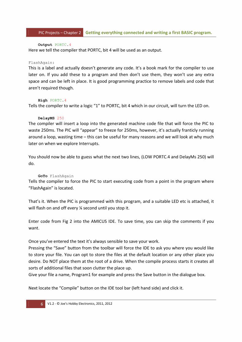
AMICUS will perform a sequence of activities including checking your text for obvious errors
and attempting to turn your statements into PIC assembler (.ASM file).
The assembler generated is automatically passed to the Microchip PIC Assembler which you
installed when you downloaded MPLAB. Whilst this is all transparent to the user, you do see a
progress bar on the screen.
Fig 4. Program compilation cycle.
You may also see a message box briefly saying “Removing Dead Code”. This is the compiler
quickly running through your code looking for things that you’ve left behind that aren’t needed
any more.
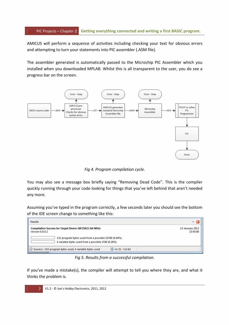
Assuming you’ve typed in the program correctly, a few seconds later you should see the bottom
of the IDE screen change to something like this:
Fig 5. Results from a successful compilation.
If you’ve made a mistake(s), the compiler will attempt to tell you where they are, and what it
thinks the problem is.

PIC Projects – Chapter 2 Getting everything connected and writing a first BASIC program.
8 V1.2 - © Joe’s Hobby Electronics, 2011, 2012
Useful tip, fix one problem at a time and start from the first one reported. Quite often, fixing
one problem will fix many others. After each fix, press the compile button again. You will
quickly get the knack of spotting and fixing errors.
Our program uses less than half of one percent of the PIC’s available program storage space,
and just one quarter or a percent of the available RAM space. Now this may seem like a lot,
and one obvious area of interest is why are there four variable bytes used, when our program
doesn’t have any variables in it.
Well, most of the variable usage and program size is down to the “DELAYMS” routines that
were used. The compiler replaced the DELAYMS instruction with a fair chuck of PIC assembler
containing delay loops, and these loops typically need variables to maintain counters.
Just out of curiosity, I added an additional DELAYMS 250 statement to the program to see how
these size values would change.
Variable usage stayed the same, and Program Bytes increased by four. Once the compiler
realised we needed the DELAYMS routine, it added in all the necessary code. The second (and
third) time we needed the DELAYMS routine, the routine was already loaded and the compiler
just added a CALL to the existing routine.
The compiler will do whatever it can to save as much space as possible, but it is only a machine
and can make mistakes. I’ll point out some things that you can do to save space and “help” the
compiler as we progress.
Fig 6. List of files generated by the compile and assembly process.
Fig 5 shows a list of the files that were left behind after the compilation and assembly process
were complete. Some other files are also generated and then automatically deleted.

PIC Projects – Chapter 2 Getting everything connected and writing a first BASIC program.
9 V1.2 - © Joe’s Hobby Electronics, 2011, 2012
Notice the file size of the .LST file. You can open these files with notepad if you want to see
what’s going on.
The file of interest is the .HEX file. This is the file that we will use to program into the PIC, and
we will do this using a Microchip PICKIT2 PIC programmer.

PIC Projects – Chapter 2 Getting everything connected and writing a first BASIC program.
10 V1.2 - © Joe’s Hobby Electronics, 2011, 2012
Starting with the PICKIT2
You should make sure that your PICKIT2 software is up to date AND you’ve downloaded the
latest device support file; check here:
http://www.microchip.com/stellent/idcplg?IdcService=SS_GET_PAGE&nodeId=1406&dDocName=en023
805
This is very important as the original PICKIT2 firmware doesn’t support the PIC were using and
even if your PICKIT2 is new, you’ve no idea how long it was sat on the shelf at the supplier.
Always check periodically for updates BUT remember to keep previous versions just in case you
have to return to an older version for some reason.
You can do all the physical PIC programming under control of MPLAB if you desire, but I prefer
to use the PICKIT2 interface program that they supply as it’s simpler to use.
There’s a similar version for the PICKIT3 as well.
Locate the PICKIT2 folder on your PC; it’s probably called something like: "C:\Program
Files\Microchip\PICkit 2 v2\"
Fig 7. PICKIT2 program located within the PICKIT2 program folder.
Create a short-cut to this program on your Windows desktop for ease of access.
You will need to connect your PICKIT2 programmer via suitable USB cable to your PC. You MUST
use a USB2 enabled USB port on your PC or USB Hub.
PICKIT2 and PICKIT3 will NOT work with the older USB 1.1 ports.
PIC Projects – Chapter 2 Getting everything connected and writing a first BASIC program.
11 V1.2 - © Joe’s Hobby Electronics, 2011, 2012
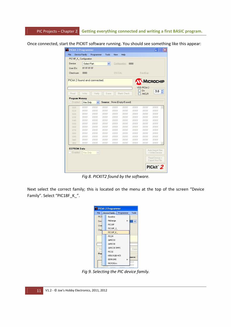
Once connected, start the PICKIT software running. You should see something like this appear:
Fig 8. PICKIT2 found by the software.
Next select the correct family; this is located on the menu at the top of the screen “Device
Family”. Select “PIC18F_K_”.
Fig 9. Selecting the PIC device family.

PIC Projects – Chapter 2 Getting everything connected and writing a first BASIC program.
12 V1.2 - © Joe’s Hobby Electronics, 2011, 2012
Now you will find the correct PIC device within the device drop-down “Device” list.
Fig 10. Selecting the PIC18F25K22 device.
We’ve now told the PICKIT2 which PIC we are expecting it to program and next we need to load
in the .HEX file that contains our program, into the software’s internal buffer.
Select “File” and then “Open” from the top menu, navigate to the location you stored your .HEX
file at, and click OK.
The PICKIT software interface should now look something like this:
Fig 11. Program .HEX file loaded into PICKIT2.

PIC Projects – Chapter 2 Getting everything connected and writing a first BASIC program.
13 V1.2 - © Joe’s Hobby Electronics, 2011, 2012
The large area in the middle of the screen shows you the actual machine code in HEX that will
be “flashed” into the PIC when programming starts. Each line starts with an address, and then is
followed by eight groups of 16 bit numbers. The reason for 16 bits instead of the more common
8 bits, is that PIC instructions are actually 14 bits long.
Just before we actually program the PIC, there is one other thing to consider.
At the bottom of the application is a section labelled “EEPROM Data” and this shows what
EEPROM data will be sent to the PIC’s EEPROM area during programming. You can, if you wish,
program the program memory and EEPROM areas independently. This has the benefit that if
you’ve got data already stored in the EEPROM area; you don’t have to overwrite it.
Also, whilst the EEPROM area can be read a near infinite number of times, it will wear out if you
keep writing to it so it’s best to tell the software to ignore this area if you’re not using it.
Fig 12. EEPROM Data Area.
Remove the tick in the Enabled box to tell the PICKIT2 software to ignore the EEPROM data
area.
Ok, now were ready to program the PIC with our .HEX file.
Whilst it doesn’t matter if the circuit is powered externally or not, I always suggest that the very
first time the PIC is programmed (or with a program for a new type of circuit if you re-use PICs),
you don’t power the PIC externally. This is because you’ve no idea how the PIC will be
configured and there’s always a possibility that when you apply power, you may accidently
either damage some of the PICs outputs, or it’s possible that the PIC will accidently set some of
its outputs to random values and cause chaos within your circuit.

PIC Projects – Chapter 2 Getting everything connected and writing a first BASIC program.
14 V1.2 - © Joe’s Hobby Electronics, 2011, 2012
Fig 13. PICKIT2 plugged into breadboard.
Connect the programmer to the PIC circuit, and click the “Write” button on the PICKIT2
software.
You should hopefully see messages scrolling up about the programming phase currently in
progress, and a progress bar should be displayed just above the “Write” button.
Once programming is complete, you should see this:
Fig 14. The PIC has successfully been programmed.
PIC Projects – Chapter 2 Getting everything connected and writing a first BASIC program.
15 V1.2 - © Joe’s Hobby Electronics, 2011, 2012
You can now switch on the power to the circuit, and the LED should start to flash.
If the LED doesn’t flash but you received the “Programming Successful” message then you’ve
probably got something wrong with your circuit. Make sure that BOTH Vss connections to the
PIC are present; also check the LED is in the right way around. Check the voltage is correct by
measuring it directly at the PIC pins.
It’s very unlikely that the PIC is faulty especially if it’s accepted the program but it can happen.
The PICKIT software has some built in diagnostics to help you debug problem connections. If
you use them READ THE INSTRUCTIONS AND FOLLOW THEM VERY CARFULLY as some tests
you must NOT have a PIC installed as you will damage it.
If you see messages like “No device detected” at the start of programming that you’ve probably
made a mistake in wiring the ICSP socket.
Every now and again during device programming you may get an error; this just happens.
Before you do anything else, try the programming cycle again. Next check all your connections
are correct and secure.
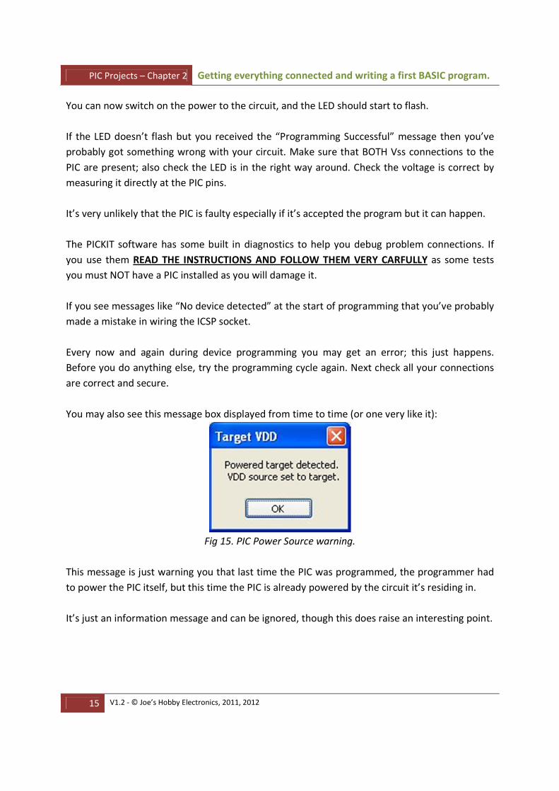
You may also see this message box displayed from time to time (or one very like it):
Fig 15. PIC Power Source warning.
This message is just warning you that last time the PIC was programmed, the programmer had
to power the PIC itself, but this time the PIC is already powered by the circuit it’s residing in.
It’s just an information message and can be ignored, though this does raise an interesting point.

PIC Projects – Chapter 2 Getting everything connected and writing a first BASIC program.
16 V1.2 - © Joe’s Hobby Electronics, 2011, 2012
Be careful with using the ICSP Pins.
PIC pins PORTB.6 and PORTB.7 are required for the ICSP interface, but they can also be used
from within your project and connecting things to these pins can sometimes confuse the
programmer. If possible try to leave these pins free for the programmer’s exclusive use. Failing
that, I always make sure that they can be isolated from the circuit easily, either by the removal
of some jumpers or quite often, popping a support IC from its socket. Sometimes inserting a
low ohm resistor between these PIC pins and the main circuit can help.
The PICKIT3 documentation suggests the following:
Do not use multiplexing on the PGC/PGD – they are dedicated for communications to the
PICKIT3. (Well, in the real world this isn’t always an option – see above).
Do not use pull-ups on the PGC/PGD – they will divide the voltage levels since these lines have
4.7K pull-down resistors in the PICKIT3.
Do not use capacitors on the MCLR – they will prevent fast transitions on the Vpp
Do not use diodes on the PGC/PGD – they will prevent bidirectional communication between
the PICKIT3 and the PIC.
For those with some experience with PIC’s, it’s fairly common to see a small capacitor on the
MCLR pin to GND to help with noise immunity and reset problems. However, this seems in
contradiction with Microchips own advice especially if you look at section 4.2 in the PIC
datasheet. I would try without the capacitor first!
It’s perfectly safe to leave the PICKIT programmer connected to the circuit as it’s designed for
this very purpose.
That’s it… the PIC is programmed, the LED should be flashing and you’ve written your first PIC
BASIC program and now would be a great time to have a read of the PIC datasheet. There really
is a LOT in there and some, if not most, will be very confusing at first read. The datasheets now
seem to assume that you already have a familiarity with previous PIC devices and so don’t
always explain things to a sufficient level of detail. As always, Google is probably your best
friend for things you don’t understand.
Also have a read of the AMICUS18 documentation. It’s not a tutorial but a reference manual,
but it’s worth just having a read. You will get a feel for what BASIC instructions are available and
other useful information.
In the chapter 3, more flashing LEDs.