wribt41wb wribp41wc wribp41mc wribp45wc … manuals... · wribt41wb wribp41wc wribp41mc wribp45wc...
TRANSCRIPT

Sep-12
Service ManualWRIBT41WB
WRIBP41WC
WRIBP41MC
WRIBP45WC
No Frost Refrigerator
1
Whirlpool of India Ltd.
Service Manual
Top Mount
No Frost Refrigerator
Whirlpool of India Ltd.
Service Manual
No Frost Refrigerator

2
INDEX
Sno. Detail Page No.
1.0 Model Range 3
2.0 Safety Precuations 4
3.0 Feature /Technical specification 6
4.0 Controls & Electronic configuration 7
5.0 Wiring Diagram 9
6.0 Assembly/Dissembly 11
7.0 Controlling the refrigerator temperature 14
8.0 Error indications & Trigger 15
9.0 Exploded Views 17
10.0 Part List 29

3
NO FROST REFRIGERATOR: MODEL RANGE
410L Dlx Better White – WRIBT41WB
410L Dlx Best White – WRIBP41WC
410L Dlx Best Suslite – WRIBP41MC
445L Dlx Best White – WRIBP45WC

4

5

6
TECHNICAL /FEATURE SPECIFICATION
MODEL 410 L Dlx 445 L Dlx
Type Frost Free Frost Free
Capacities (L) total net 410L 445 L
Product Dimensions (mm)
Width 700 700
Height 1658 1775
Depth 740 740
Gross Weight (kg) 85 90
Voltage / Hz 220/50Hz 220-240V/50-60Hz
Compressor ADW66AK EMY65HLC
Oil Capacity ISO 22 (220 ml) ISO 22 (280 ml)
Comp. Run Capacitor CBB60
4microF/450VAC
XS351505XLUB
5 microF/350VAC
PTC Relay QP2-15 PTH7M220MD3
Motor Protector JUX-23GCF 4TM283KFBYY-53
Fan motor MES 3W MI 9.8W
Split Diffuser NO NO
Deodorizer Yes Yes
Number of Shelves 2 2
Type of Shelves Glass Glass
Humidity Control
RC Illumination ( 6 LED Bank ) Illumination by LED’s Illumination by LED’s
FC Illumination ( 2 LED Bank ) Illumination by LED’s Illumination by LED’s
Bottle Separator YES YES
Packet Separator YES YES
Can Rack NO NO
Egg tray 1 No. 1 No.
Removable Ice twister YES –Plastic YES –Plastic
Puff pastry YES YES
Beer caddy YES YES
Thaw zone YES YES
Beer central YES YES
Freezer Door Bins 2 2
Refrigerator Door Bins 4 4
Door lock NO NO
Handle FLUSH FLUSH
Roof Rail NO NO
Cabinet Stopper YES YES
POT Control in RC compartment YES YES
Fast Forward Cool Operation NO NO
Door Alarm YES YES
Auto Power save mode NO NO
7
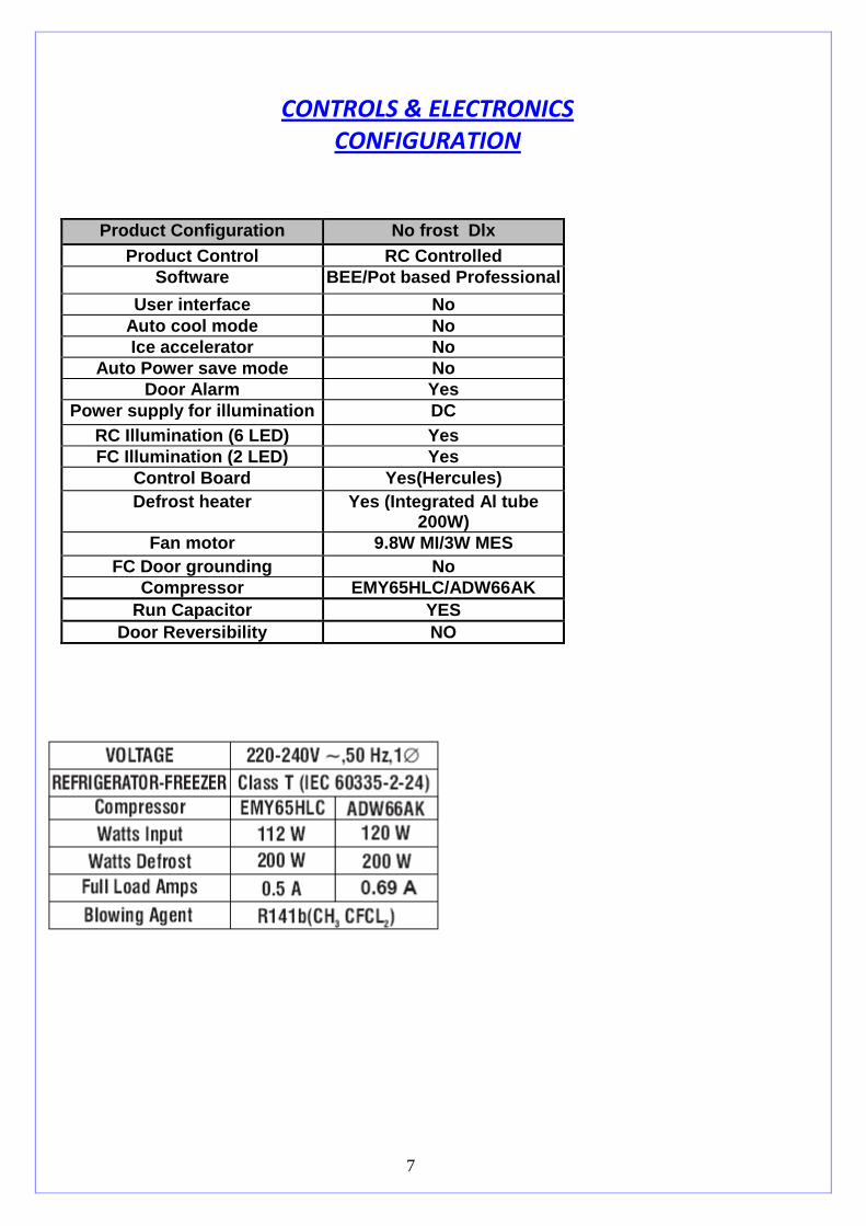
CONTROLS & ELECTRONICS
CONFIGURATION
Product Configuration No frost Dlx
Product Control RC Controlled Software BEE/Pot based Professional
User interface No Auto cool mode No Ice accelerator No
Auto Power save mode No Door Alarm Yes
Power supply for illumination DC RC Illumination (6 LED) Yes FC Illumination (2 LED) Yes
Control Board Yes(Hercules) Defrost heater Yes (Integrated Al tube
200W) Fan motor 9.8W MI/3W MES
FC Door grounding No Compressor EMY65HLC/ADW66AK
Run Capacitor YES Door Reversibility NO

8
Top Mount: Deluxe models:
This refrigerator is managed by an Electronic System, mainly consisting of the components:
• Electronic Control Board (Hercules- Dlx (BEE))
• POT (Potentiometer) in case of Dlx (BEE) models only.
• Temperature Sensors {refrigerator, Defrost}
• Compressor ( With Run capacitor)
• Freezer Fan Motor (AC)
• Defrost Heater ( Integrated Al tube 200W)
• Door Open Sensing
These components are described as shown below.
– Electronic Control
The complete operation of this product is done by the Electronic Control, Functions of this models are
fully controlled by the Micro-controller IC which executes the functions according to the needs, turning
the components On or Off through received/managed signals, such as:
- Compressor On/Off
- Defrost Heater On/Off
- Temp setting in refrigerator Compartment, through received signals by the POT along with the RC &
FC Sensors Temp. Feedback.
- Door open sensing / Alarm
- Among many other functions controlled by its software.
The Electronic Control is located at the rear of the refrigerator, next to the cabinet and besides the
Compressor, inside a plastic box. Cables going inside the product, using connectors that do not permit an
assembling failure do its connection to the mains and its components.
Note: For more details see wiring Diagram.

9
Wiring Diagram : Top Mount – No Frost Dlx
Refrigerant Charging quantity:

10

11
Identification of connectors:
CN1 (Connector 1)(6 pin MLX) – Compressor, Heater and Power Cord
CN2 (Connector 2)(8 pin minifit) – Temperature Sensors/POT
CN3 (Connector 3)(6 pin minifit) – RC/FC LED
WARNING
Electrostatic Discharge Risk
Do not touch the Circuit components, because you can damage fuse/burned or weaken the
board.
Always handle the Boards by the sides/plastic holder.
Spare parts/stock boards if outside the BOX must be kept in anti-static packaging.
Connector 1
Connector 2
Connector 3

12
Assembly &Disassembly Procedure
Disassembly Procedure:
A) Core Board Box
1. Disconnect the Power cord from the Mains supply.
2. Remove the Mounting Screws and connectors.
IMPORTANT
# Be careful when using the Multimeter measuring probes, as they may damage the
Connector terminals.
# Be careful when removing the electronic board connectors, as they are latched.
Remove them at right angles with no side movements
Mounting screws

13
1. Defrost Sensor mounted on the Evaporator tube.
2. Removing the Defrost Sensor
Defrost Temperature Sensor – NTC
It’s located at the freezer compartment, along with the Evaporator. The Defrost Sensor is responsible
for sending signals to the electronic control, which will command the ending of the defrost, turning
off the Defrost Heater,
This does a similar function to the well-known Defrost Bimetal
NEVER replace these Sensors with the Sensor Kit used in the Symphony model.
In the need of replacing one of the Temperature Sensors, Replace the full RC Sensor harness. Directly
replace the relevant RC Sensor harness. Do not try to repair the harness for the faulty Thermistor.
IMPORTANT Never change the position of such Sensors, as their functional characteristics can be
modified. This sensor also informs the temperature conditions of the Evaporator when
the product is activated (plugged in electricity) indicating to the Electronic Control the
correct start up to be followed, for instance, manufacturing ,default or the previous
programming done by the user, compressor delay , etc.
WARNING These Sensors (refrigerator & Defrost) Are Compatible with Each Other, but
Are not compatible with the Sensors of the previous Model (SYMPHONY)

14
Cooling control:
Dlx models:-
Door Open Sensing Alarm
Door open sensing alarm activates or gives beep if the door is kept open for more than 2 min.
During the Door opening beep alarm if the door is closed then the alarm gets deactivated.
Adaptive Defrost Control The defrost cycle shall be started after the Defrost timer has expired. According to the following defrost procedure:
Defrost must be executed every time one of the following event occurs:
1. After 8 hours (+/-10 minutes) of compressor running, calculated considering just the thermostat function.
2. When the product goes into defrost (in thermostatic mode) a time period of 20 min (+/-1 minute) is allowed
to complete the time to defrost.
3. If the door open time > 10 min, within first 5 hrs of cumulative compressor run time, defrost is initiated at
5hrs.
4. If the door open time < 10 min or If there is at least one door opening up to 8 hrs of compressor running then
defrost time is as per point 1.
5. If there is no door opening up to 8 hrs of compressor running than defrost time will be 18hrs
6. If there is no door opening for 8 hrs, & there is door opening between 8 to 18 hrs of compressor running,
defrost will take place immediately.
The 5th
, 8th or 18th
hr of compressor running (defrost timer) consist of the sum of all the compressor’s ON time,
independently of the number of compressor cycles and how many time the compressor was ON.

15
Safe mode routine During Constant fault condition, the Electronic Control will assume a safety routine, as in normal
cycle, trying to keep food conservation, however will work as follows:
• Compressor and Fan Motors will be on for 25 minutes and then will turn off for 20 minutes.
• Interval set between defrosts will be fixed in every 5 hours of the Compressor activity
• Every defrost time is fixed for 20 minutes. No dependency on defrost sensor for Cut Off temp of
15°C
Note: - • There is no Service routine provided in this model.
• To check whether Heater is working fine or not, service person can use the Power up initialization
function of the model, where Product need to be switched Off & need to be ensured that the temp at
the FC sensor is >0°c, then after making the product ON product goes into the Power up initialization
mode where after product switch ON, heater gets activated for the first 5 seconds & then it goes to the
compressor mode after 3 minutes of heater getting off. Service person can make the use of this 5
seconds where by putting the Tong tester one can easily identify the healthy/faulty condition of the
heater through the driving current displayed on the tong tester it self at the Electronic core board box
location without opening the FC Plenum.
• In case of any Aluminum foil wrapping found over the Wiring harness either in FC compartment, RC
Compartment or in the Compressor deck area, the same Al foil should be carefully replaces in same
fashion after servicing
• In case of any detailed technical information please check with the Dlx technical specification.
Normal
Compressor
/Product
running
Mode
Sensor
Failed??
(Open/Shor
t Mode)
{RC, FC
sensor or
POT
Start Safe mode
routine
after 2 min of
error
Event in sensor
Yes
No
Whether
sensor/POT
is
repaired/cor
rected??
No
Yes

16
Board Level Diagnostics for :
* Thermistor Failure FC/RC
* Potentiometer Failure
1 First Turn Off the Product & disconnect the Plug.
2 Remove the 3 connectors of Control Board.
3 For Thermistor Failure FC/RC
* Check resistance on pin no. 4 & 8 of CN2 (8 pin connector) for RC Thermistor.
* Check resistance on pin no. 2 & 6 of CN2 (8 pin connector) for FC Thermistor.
* IF thermistor is open then the resistance is infinite.
* IF thermistor is short then the resistance is zero.
* IF resistance lie between 0-22 KOhms the themistor is OK.
5 Potentiometer Failure
* Check resistance on pin no. 1 & 5 of CN2 (8 pin connector) for Potentiometer.
* It should lie between 0 to 22 K ohms

17
EXPLODED VIEWS:

18

19

20

21

22

23
1

24

25

26

27
NOTE –To replace EMY65HLC Compressor in place of EGZ80HLC use reverse port suction compliment . Spare part No. - 137, Whirlpool Part No.A2294830000

28
Part No: - A2241780000
INTEGRATED DEFROST HEATER,KENMORE-ONYX
PART LIST FOR ONYX-AUSTRALIA

29
SERVICABLE PART-NEO-AUSTRALIA
Sr
no
WOIL PART
NUMBER
DESCRIPTION COMMODITY Model 410L 410L 410L 445L
WRIBT41WB WRIBP41WC WRIBP41MC WRIBP45WC
1 A201354000D PHILIPS HEAD SCREW M5.5X1.8 SCREW 8 EA 8 EA 8 EA 8 EA
2 A2245960000 Spacer Sub Assy - Onyx PLASTIC 1 EA 1 EA 1 EA 1 EA
3 A2252540000 Grommet Compressor-THK PLASTIC 4 EA 4 EA 4 EA 4 EA
4 A201378000A SOUND DEADENING- EVAPORATOR RUBBER 1 EA 1 EA 1 EA 1 EA
5 W10431429 DEFROST WATER TRAY Assembly - Onyx PLASTIC 1 EA 1 EA 1 EA 1 EA
6 A2222710000 SOUND DAMPNER RUBBER 1 EA 1 EA 1 EA 1 EA
7 D111204100D HEX NYLOC NUT M6 SCREW 4 EA 4 EA 4 EA 4 EA
8 W10464313 Heat Shield NEO 1 EA 1 EA 1 EA 1 EA
9 A224539000B Compliment Suction Line - Onyx EMY75HLC COPPER 1 EA 1 EA 1 EA 1 EA
10 A211638380A COMPRESSOR SLEEVE-GNF PLASTIC 4 EA 4 EA 4 EA 4 EA
11 A2221180000 FAN BLADE, 110MM DUO PLASTIC 1 EA 1 EA 1 EA 1 EA
12 A224268000B SUB ASSY PLENUM BACK -ONYX ASSY 1 EA 1 EA 1 EA 1 EA
13 A201495000C KNOB -FREEZER CONTROL PLASTIC 1 EA 1 EA 1 EA 1 EA
14 A2221170000 MI AC MOTOR FOR DUO ELECTRONICS 1 EA 1 EA 1 EA 1 EA
15 A222119000B BRACKET FAN MOTOR MOUNTING PLASTIC 1 EA 1 EA 1 EA 1 EA
16 A222120000B HOUSING, FAN MOTOR, DUO PLASTIC 1 EA 1 EA 1 EA 1 EA
17 A222148000A GROMET FOR FIXING MOTOR PLASTIC 2 EA 2 EA 2 EA 2 EA
18 W10479945 SUB ASSY PLENUM FRONT GRAPHICS-NEO ASSY 1 EA 1 EA 1 EA 1 EA
19 A2244120000 MANUAL DAMPER FOR AUSTRALIA - ONYX PLASTIC 1 EA 1 EA 1 EA 1 EA
20 A2240730000 COMPLEMENT EPS, PLENUM BACK- ONYX ASSY 1 EA 1 EA 1 EA 1 EA
21 A2242540000 COMPLEMENT PLENUM FRONT-ONYX ASSY 1 EA 1 EA 1 EA 1 EA
22 A2241810000 PLENUM SCREW CAP - ONYX PLASTIC 4 EA 4 EA 4 EA 4 EA
23 W10487837 VEG CRISPER NEO PLASTIC 1 EA 1 EA 1 EA 1 EA
24 W10479952 SUB ASSY- VEG CRISPER COVER-NEO ASSY 1 EA 1 EA 1 EA 1 EA
25 W10479935 FREEZER BIN - NEO WITH GRAPHICS PLASTIC 2 EA 2 EA 2 EA 2 EA
26 W10479936 BOTTLE BIN - NEO WITH GRAPHICS PLASTIC 1 EA 1 EA 1 EA 1 EA
27 A224133000A FC GRILL – ONYX PLASTIC 1 EA 1 EA 1 EA 1 EA
28 A224041000B GLASS SHELF – ONYX PLASTIC 1 EA 1 EA 1 EA 1 EA
29 W10444262 Sub-aseembly - Beer Chiller Central ASSY 0 EA 1 EA 1 EA 1 EA
30 A2240510000 EGG TRAY – ONYX PLASTIC 1 EA 1 EA 1 EA 1 EA
31 A224059000A PACKET SEPARATOR - ONYX PLASTIC 1 EA 1 EA 1 EA 1 EA
32 A2241720000 BUSH, CHILLER DOOR-ONYX PLASTIC 1 EA 1 EA 1 EA 1 EA
33 W10479937 MULTI USE BIN - NEO WITH GRAPHICS PLASTIC 2 EA 2 EA 2 EA 2 EA
34 A2240650000 BOTTLE SEPARATOR - ONYX PLASTIC 1 EA 1 EA 1 EA 1 EA
35 W10479942 FREEZER BIN RC - NEO WITH GRAPHICS PLASTIC 1 EA 1 EA 1 EA 1 EA
36 A224357000A BIN SEPARATOR - ONYX PLASTIC 1 EA 1 EA 1 EA 1 EA
37 A2245140000 Crisper Cover Foam Pad PLASTIC 6 EA 6 EA 6 EA 6 EA
38 A2290920000 THERMISTER CLIP - RC, OPAL STEEL 1 EA 1 EA 1 EA 1 EA
39 W10416855 CENTRE HINGE ASSY FC/RC 3D TRIONYX ASSY 1 EA 1 EA 1 EA 1 EA
40 W10444351 HINGE TOP ASSY-DLX NEO/L-60 ASSY 1 EA 1 EA 1 EA 1 EA
41 W10507748 TOP HINGE COVER NEO-DLX WHITE PLASTIC 1 EA 1 EA 0 EA 1 EA
42 W10478232 COVER CENTRE RAIL ONYX PLASTIC 1 EA 1 EA 1 EA 1 EA
43 A224198200A SOCKLE, BOTTOM HINGE WHITE, RH - ONYX PLASTIC 1 EA 1 EA 0 EA 1 EA
44 A224199200A SOCKLE, BOTTOM HINGE WHITE, LH - ONYX PLASTIC 1 EA 1 EA 0 EA 1 EA
45 A224234200A SOCKLE CAP WHITE - ONYX PLASTIC 1 EA 1 EA 1 EA 1 EA
46 W10496988 SOCKLE BOTTM HINGE CHARCOAL GREY, RH NEO PLASTIC 0 EA 0 EA 1 EA 0 EA
47 W10496989 SOCKLE BOTTM HINGE CHARCOAL GREY, LH NEO PLASTIC 0 EA 0 EA 1 EA 0 EA
48 A201356000B SCREW- Philips Head ,M4.8 x 16 SCREW 3 EA 3 EA 3 EA 3 EA
49 D111155700K S.T. SCREW (8*13)/Crescendo SCREW 2 EA 2 EA 2 EA 2 EA
50 A2243490000 M 4.2 X 16 SELF TAPPING SCREW - ONYX SCREW 4 EA 4 EA 4 EA 4 EA
51 A2243500000 M 4.8 X 13 SELF TAPPING SCREW - ONYX SCREW 5 EA 5 EA 5 EA 5 EA
52 A222376000A 4.8 X 16 SELF TAPP AB TYPE SS SCREW 1 EA 1 EA 1 EA 1 EA
53 A222374000A 4.2 X 25 SELF TAPP AB TYPE SS SCREW 8 EA 8 EA 8 EA 8 EA
54 W10418501 Screw Trilobular M6 X 1.0 Hex Head SCREW 4 EA 4 EA 4 EA 4 EA
55 A2246190000 POWER CORD AUSTRALIA - ONYX ELECTRONICS 0 EA 0 EA 0 EA 1 EA
56 A2117510000 THERMAL FUSE WITH CONNECTOR
ELECTRONICS 1 EA 1 EA 1 EA 1 EA
57 A224052000B HARNESS RC, DLX-ONYX ELECTRONICS 1 EA 1 EA 1 EA 1 EA
58 A224249000A HARNESS FAN MOTOR - ONYX ELECTRONICS 1 EA 1 EA 1 EA 1 EA
59 A222248000A POT PCB ASSEMBLY / Proton ELECTRONICS 1 EA 1 EA 1 EA 1 EA
60 W10492990 H2 CORE BOARD BOX SUB ASSY-ONYX AUST ELECTRONICS 1 EA 1 EA 1 EA 1 EA

30
61 A224099000A RC PCB LENS ASSY - ONYX ELECTRONICS 1 EA 1 EA 1 EA 1 EA
62 A224104000A FC PCB LENS ASSY - ONYX ELECTRONICS 1 EA 1 EA 1 EA 1 EA
63 W10479944 COVER AIR DIFFUSER DLX GRAPHICS- NEO PLASTIC 1 EA 1 EA 1 EA 1 EA
64 A2242770000 COVER - DEODERISER - ONYX PLASTIC 1 EA 1 EA 1 EA 1 EA
65 A224159000B SUPPORT DEODERISER COVER-ONYX PLASTIC 1 EA 1 EA 1 EA 1 EA
66 A224163000B SUB ASSY DIFFUSER EPS, 450L -ONYX ASSY 1 EA 1 EA 1 EA 1 EA
67 A224042000A CAP, COVER AIR DIFFUSER SCREW-ONYX PLASTIC 2 EA 2 EA 2 EA 2 EA
68 A224097000A EXTENSION COVER AIR DIFFUSER, 450L-ONYX PLASTIC 0 EA 0 EA 0 EA 1 EA
69 A224402000A ASSY PLATE LEVELLER, MODIFIED - ONYX ASSY 1 EA 1 EA 1 EA 1 EA
70 A224142000H COMPRESSOR BASE PLATE ASSY - ONYX ASSY 1 EA 1 EA 1 EA 1 EA
71 A224109000C BOTTOM HINGE AND ROLLER ASSY RH - ONYX ASSY 1 EA 1 EA 1 EA 1 EA
72 W10464332 Drain Tube Extension NEO PLASTIC 1 EA 1 EA 1 EA 1 EA
73 W10477273 SHOULDER SCREW NF 06 SCREW 8 EA 8 EA 8 EA 8 EA
74 A224107000C COMPLEMENT, STOP DOOR RC - ONYX PLASTIC 1 EA 1 EA 1 EA 1 EA
75 A2243610000 WASHER DOOR STOPPER - ONYX STEEL 1 EA 1 EA 1 EA 1 EA
76 W10497994 BEER CADDY ASSY WITH BOTTLE OPENER ASSY 1 EA 1 EA 1 EA 1 EA
77 W10482605 Assly, Ice Twister, Removable,w carton ASSY 1 EA 1 EA 1 EA 1 EA
78 W10410592 Puff pastry Assy - Australia ASSY 1 EA 1 EA 1 EA 1 EA
79 W10432625 Puff Pastry Rail - Right PLASTIC 1 EA 1 EA 1 EA 1 EA
80 W10432627 Puff Pastry Rail - Left PLASTIC 1 EA 1 EA 1 EA 1 EA
81 W10432661 Defrost Shelf Frame - Australia PLASTIC 0 EA 1 EA 1 EA 1 EA
82 W10432663 Defrost Tray - Australia PLASTIC 0 EA 1 EA 1 EA 1 EA
83 W10495835 Double Adhesive foam pad-CoreBoard Box FOAM PAD 1 EA 1 EA 1 EA 1 EA
84 A2253880000 COMP ASSY EMY65HLC COMPRESSOR 1 EA 1 EA 1 EA 1 EA
85 W10505097 FC FOAMED DOOR DLX FLUSH NEO WHITE FOAMED
DOOR
1 EA 1 EA 0 EA 1 EA
86 W10505104 RC FOAMED DOOR 450L FLUSH NEO WHITE FOAMED
DOOR
0 EA 0 EA 0 EA 1 EA
87 W10505101 RC FOAMED DOOR 410L FLUSH NEO WHITE FOAMED
DOOR
1 EA 1 EA 0 EA 1 EA
88 W10505100 FC FOAMED DOOR DLX FLUSH NEO SUSLITE FOAMED
DOOR
0 EA 0 EA 1 EA 0 EA
89 W10505102 RC FOAMED DOOR 410L FLUSH NEO SUSLITE FOAMED
DOOR
0 EA 0 EA 1 EA 0 EA
90 A2241020000 HOUSING RC LED DEODERISER - ONYX PLASTIC 1 EA 1 EA 1 EA 1 EA
91 A2241520000 HOUSING FC LED - ONYX PLASTIC 1 EA 1 EA 1 EA 1 EA
92 A2253030000 SWITCH ROCKER ARM, NC- ESBEE W welded ELECTRONICS 2 EA 2 EA 2 EA 2 EA
93 W10478024 SCREW-TRILOBULAR M6X1.0 HEX HEAD SCREW 8 EA 8 EA 8 EA 8 EA
94 W10493019 CHILLER, STOPPER, LINER,NEO PLASTIC 2 EA 2 EA 2 EA 2 EA
95 A2241780000 INTEGRATED DEFROST HEATER,KENMORE-ONYX HEATER 1 EA 1 EA 1 EA 1 EA
96 W10471834 PUSH IN GASKET (B)- FC TRIONYX / NEO GASKET 0 EA 0 EA 0 EA 1 EA
97 W10473960 Gasket - RC 450L GASKET 0 EA 0 EA 0 EA 1 EA
98 W10471836 PUSH IN GASKET (B) - RC 410L NEO GASKET 1 EA 1 EA 1 EA 0 EA
99 W10456029 WANBAO, ADW66AK COMPRESSOR 1 EA 1 EA 1 EA 1 EA
100 A224248000D COMPLIMENT SUCTION LINE - ONYX EG-80HLC COPPER 1 EA 1 EA 1 EA 1 EA
101 W10456032 ONYX 410L AUST POWER CORD ELECTRONICS 1 EA 1 EA 1 EA 1 EA
102 A2253020000 MES brushless fan motor (160-260) ELECTRONICS 1 EA 1 EA 1 EA 1 EA
103 A2245540000 Fan Motor Harness - MES Fan Motor Onyx ELECTRONICS 1 EA 1 EA 1 EA 1 EA
104 W10494984 GROMET SLEEVE STEEL 4 EA 4 EA 4 EA 4 EA
105 A2240390000 CHILLER - ONYX PLASTIC 1 EA 0 EA 0 EA 0 EA
106 W10502344 GASKET SUB-ASSY FC NEO PART GASKET 1 EA 1 EA 1 EA 0 EA
107 W10463885 TOP HINGE COVER NEO-DLX CHARCOAL GREY PLASTIC 0 EA 0 EA 1 EA 1 EA
108 W10412075 HANDLE FC FRONT FLUSH WHITE PLASTIC 1EA 1EA 0EA 1EA
109 W10511612 HANDLE FC BACK FLUSH WHITE PLASTIC 1EA 1EA 0EA 1EA
110 W10477284 HANDLE FC FRONT FLUSH EXPORTS PLASTIC 0EA 0EA 1EA 0EA
111 W10412074 HANDLE FC BACK FLUSH WARM SILVER2 PLASTIC 0EA 0EA 1EA 0EA
112 W10412079 HANDLE RC FRONT FLUSH WHITE PLASTIC 1EA 1EA 0EA 1EA
113 W10511612 HANDLE RC BACK FLUSH WHITE PLASTIC 1EA 1EA 0EA 1EA
114 W10477285 HANDLE RC FRONT FLUSH WARM SILVER2 PLASTIC 0EA 0EA 1EA 0EA
115 W10412078 HANDLE RC BACK FLUSH WARM SILVER2 PLASTIC 0EA 0EA 1EA 0EA