wpo-12 hsupa principleand plan-45
TRANSCRIPT

7/30/2019 WPO-12 HSUPA Principleand Plan-45
http://slidepdf.com/reader/full/wpo-12-hsupa-principleand-plan-45 1/45
HSUPA Technology Principle and
Plan
ZTE University

7/30/2019 WPO-12 HSUPA Principleand Plan-45
http://slidepdf.com/reader/full/wpo-12-hsupa-principleand-plan-45 2/45
HSUPA Brought in Requirements
Basic Principle of HSUPA
Key Technologies of HSUPA
HSUPA Plan
Content
7/30/2019 WPO-12 HSUPA Principleand Plan-45
http://slidepdf.com/reader/full/wpo-12-hsupa-principleand-plan-45 3/45
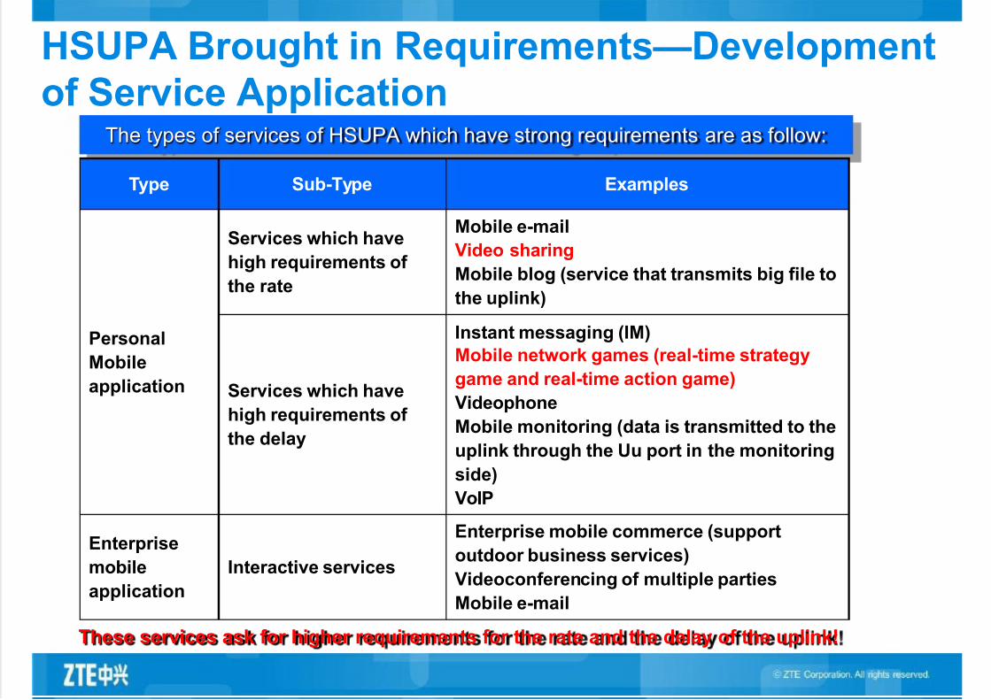
HSUPA Brought in Requirements—Development
of Service ApplicationThe types of services of HSUPA which have strong requirements are as follow:
Type Sub-Type Examples
Personal
Mobile
application
Services which have
high requirements of
the rate
Mobile e-mail
Video sharing
Mobile blog (service that transmits big file to
the uplink)
Services which have
high requirements of
the delay
Instant messaging (IM)
Mobile network games (real-time strategy
game and real-time action game)
Videophone
Mobile monitoring (data is transmitted to the
uplink through the Uu port in the monitoring
side)
VoIP
Enterprise
mobile
application
Interactive services
Enterprise mobile commerce (support
outdoor business services)
Videoconferencing of multiple parties
Mobile e-mail
These services ask for higher requirements for the rate and the delay of the uplink!
7/30/2019 WPO-12 HSUPA Principleand Plan-45
http://slidepdf.com/reader/full/wpo-12-hsupa-principleand-plan-45 4/45
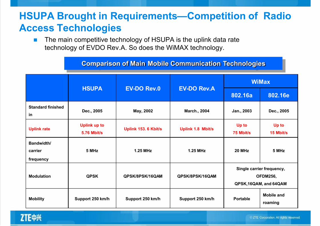
HSUPA Brought in Requirements—Competition of Radio
Access Technologies The main competitive technology of HSUPA is the uplink data rate
technology of EVDO Rev.A. So does the WiMAX technology.
HSUPA EV-DO Rev.0 EV-DO Rev.AWiMax
802.16a 802.16e
Standard finished
inDec., 2005 May, 2002 March., 2004 Jan., 2003 Dec., 2005
Uplink rateUplink up to
5.76 Mbit/sUplink 153. 6 Kbit/s Uplink 1.8 Mbit/s
Up to
75 Mbit/s
Up to
15 Mbit/s
Bandwidth/
carrier
frequency
5 MHz 1.25 MHz 1.25 MHz 20 MHz 5 MHz
Modulation QPSK QPSK/8PSK/16QAM QPSK/8PSK/16QAM
Single carrier frequency,
OFDM256,
QPSK,16QAM, and 64QAM
Mobility Support 250 km/h Support 250 km/h Support 250 km/h PortableMobile and
roaming
Comparison of Main Mobile Communication Technologies

7/30/2019 WPO-12 HSUPA Principleand Plan-45
http://slidepdf.com/reader/full/wpo-12-hsupa-principleand-plan-45 5/45
HSUPA Brought in Requirements—Usage of HSDPA in
Large Scale According to the statistic data of GSA,
up to Q2 of 2007, there are 178
HSDPA commercial networks. Itpredicts that HSDPA networks will be
established in large scale in the
following several years.
The large scale application of HSDPA
is the pilot run of the mobile data
service. Users will ask morerequirements for the rate and
response speed for the uplink. The
brought-in HSDPA will bring in the
requirements for HSUPA.
Seeing from the life cycle predicted by
the telecom research institution of
ministry of information, HSUPA will be
brought in in 2008.
The commercial process of HSDPA brings along
the market application of HSUPA.
There are 53 HSDPA commercial
networks with 3.6 Mbit/s rate in the
globe.

7/30/2019 WPO-12 HSUPA Principleand Plan-45
http://slidepdf.com/reader/full/wpo-12-hsupa-principleand-plan-45 6/45
To meet the performance requirements of uplink transmission of users, the high speed uplink
packet access (HSUPA) research project is started after the regulation for high speed
downlink packet access (HSDPA) for 3GPP is released.
The technology regulations of HSUPA are made on the R6 version of 3GPP. The first HSUPA
regulation edition was published in Dec., 2004. The remaining problems of the HSUPA
technology regulations were basically solved in 2005.
The peak data rate of HSUPA can achieve 5.76 Mbit/s in theory. This is the uplink data
transmission technology of high rate. The purpose is to improve the uplink air capacity usage
rate and meet the user requirements by improving the throughput rate of the cell and the
coverage of the high data rate.
To support high rate data transmission, a new transmission channel enhanced-data channel
(E-DCH) is brought in for HSUPA. E-DCH can be used for transmitting packet service data. It
supports variable rate transmission, quick packet scheduling, and quick retransmission.
Overview of HSUPA Technologies
7/30/2019 WPO-12 HSUPA Principleand Plan-45
http://slidepdf.com/reader/full/wpo-12-hsupa-principleand-plan-45 7/45
HSUPA Brought in Requirements
Basic Principle of HSUPA
Key Technologies of HSUPA
HSUPA Plan
Content

7/30/2019 WPO-12 HSUPA Principleand Plan-45
http://slidepdf.com/reader/full/wpo-12-hsupa-principleand-plan-45 8/45
HSUPA Protocol Schema
PHY PHY
EDCH FP EDCH FP
Iub UE NodeB Uu
DCCH DTCH
TNL TNL
DTCH DCCH
MAC-e
SRNC
MAC-d
MAC-e
MAC-d
MAC-es /MAC-e
MAC-es
Iur
TNL TNL
DRNC
UE side: The new brought-in MAC entity MAC-es/MAC-e is under MAC-d. MAC-es/MAC-e is used for
quick HARQ retransmission, information scheduling and data multiplexing, and E-TFC (E-DCH TFC)
selection.
Node B side: The new MAC entity MAC-e is brought in. It is used for HARQ retransmission, resource
scheduling, and MAC-e multiplexing.
SRNC side: The new MAC entity MAC-es is brought in. It is used for reordering and macro diversity
combination.

7/30/2019 WPO-12 HSUPA Principleand Plan-45
http://slidepdf.com/reader/full/wpo-12-hsupa-principleand-plan-45 9/45
Characteristics of Key Technologies of
HSUPA
The HSUPA technology is mainly used for adding the E-DCH
dedicated physical data channel (E-DPDCH) (up to 4 channelsfor each UE) and an E-DCH dedicated physical control channel(E-DPCCH) for the UE in the uplink. It is also used for addingthe public physical channels E-HICH, E-AGCH, and E-RGCHin the downlink.
E-DPDCH is used for transmitting the uplink data. The
minimum spread spectrum factor is 2 or 4. The modulationmethod is QPSK. 2 ms TTI is brought in for the channel.Meanwhile, 10 ms TTI is reserved.
The dedicated uplink E-DPCCH channel and the publicchannels (E-HICH, E-AGCH, and E-RGCH) work together tofinish the information interaction (including ACK/NACK, uplink
grant, and control signaling related to E-DCH) of HARQ and itsprocess.
The maximum rate of the physical channel of each E-DPDCHis 1.92 Mbit/s ( 2 ms TTI, QPSK, maximum SF = 2). Themaximum service rate of each UE is 5.76 Mbit/s.

7/30/2019 WPO-12 HSUPA Principleand Plan-45
http://slidepdf.com/reader/full/wpo-12-hsupa-principleand-plan-45 10/45
Structure of the MAC Layer in the UE side
AssociatedDownlinkSignaling
E-DCH
MAC-d
FACH RACH
DCCH DTCHDTCH
DSCH DCH DCH
MAC Control
USCH( TDD only )
CPCH( FDD only )
CTCHBCCHCCCH SHCCH( TDD only )
PCCH
PCH FACH
MAC-c/sh
USCH( TDD only )
DSCH
MAC-hs
HS-DSCH
AssociatedUplink
Signaling
AssociatedDownlinkSignaling
MAC-es /MAC-e
AssociatedUplink
Signaling
The new MAC-es/MAC-e entity is brought in in the UE side to control E-DCH.
Used for quick HARQ retransmission, scheduling and data multiplexing, and E-TFC (E-
DCH TFC) selection.

7/30/2019 WPO-12 HSUPA Principleand Plan-45
http://slidepdf.com/reader/full/wpo-12-hsupa-principleand-plan-45 11/45
The MAC-e/MAC-es Entity Structure in the UE Side
MAC - es/e
MAC – Control
Associated UplinkSignaling E - TFC
( E - DPCCH )
To MAC - d
HARQ
Multiplexing and TSN setting E - TFC Selection
Associated Scheduling
Downlink Signaling ( E - AGCH / E - RGCH(s) )
Associated ACK/NACK
signaling
( E - HICH )
7/30/2019 WPO-12 HSUPA Principleand Plan-45
http://slidepdf.com/reader/full/wpo-12-hsupa-principleand-plan-45 12/45
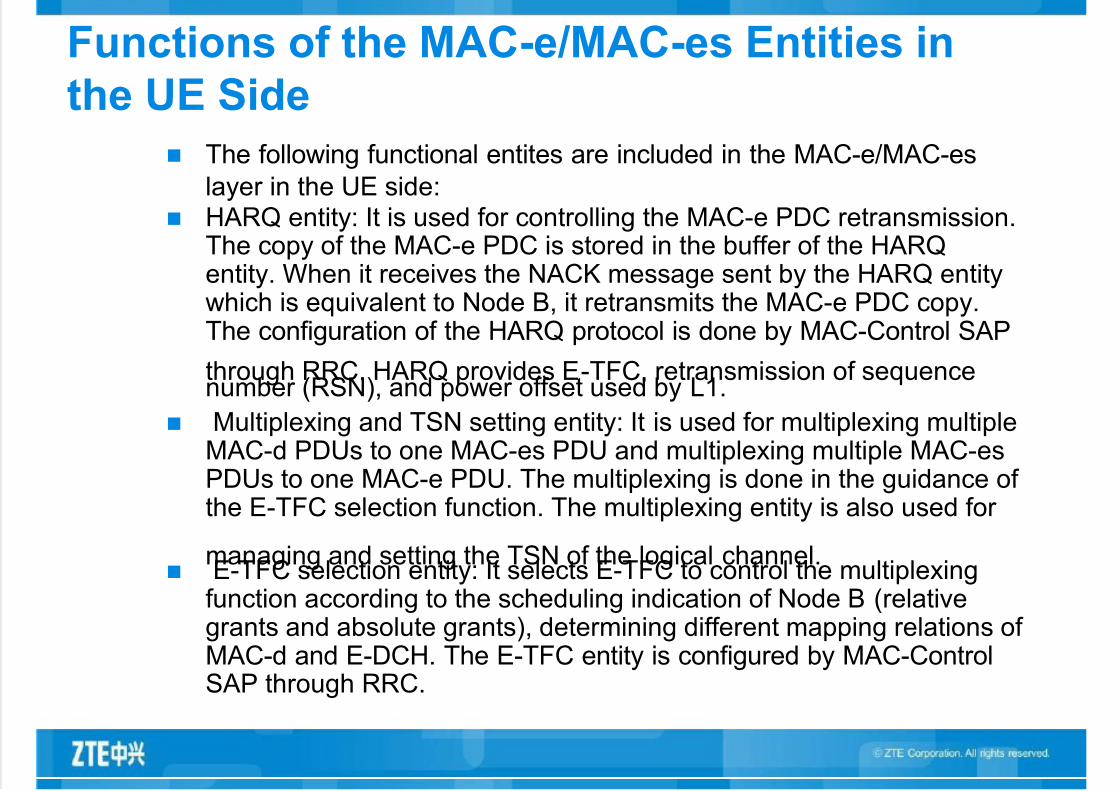
Functions of the MAC-e/MAC-es Entities in
the UE Side
The following functional entites are included in the MAC-e/MAC-es
layer in the UE side:
HARQ entity: It is used for controlling the MAC-e PDC retransmission.The copy of the MAC-e PDC is stored in the buffer of the HARQentity. When it receives the NACK message sent by the HARQ entitywhich is equivalent to Node B, it retransmits the MAC-e PDC copy.The configuration of the HARQ protocol is done by MAC-Control SAP
through RRC. HARQ provides E-TFC, retransmission of sequencenumber (RSN), and power offset used by L1.
Multiplexing and TSN setting entity: It is used for multiplexing multipleMAC-d PDUs to one MAC-es PDU and multiplexing multiple MAC-esPDUs to one MAC-e PDU. The multiplexing is done in the guidance of the E-TFC selection function. The multiplexing entity is also used for
managing and setting the TSN of the logical channel. E-TFC selection entity: It selects E-TFC to control the multiplexing
function according to the scheduling indication of Node B (relativegrants and absolute grants), determining different mapping relations of MAC-d and E-DCH. The E-TFC entity is configured by MAC-ControlSAP through RRC.

7/30/2019 WPO-12 HSUPA Principleand Plan-45
http://slidepdf.com/reader/full/wpo-12-hsupa-principleand-plan-45 13/45
PDC Processing in the MAC Layer in the UE
Side
MAC-d Flows
MAC-es PDUMAC-e header
DCCH DTCH DTCH
HARQprocesses
Multiplexing
DATA
MAC-d DATA
DATA
DDI N Padding
(Opt)
RLC PDU:
MAC-e PDU:
L1
RLC
DDI N
Mapping info signaled over RRC
PDU size, logical channel id, MAC-d flowid => DDI
DATA DATA
MAC-d PDU:
DDI
Header
MAC-es/e
NumberingMAC-es PDU: TSN DATA DATANumbering Numbering
7/30/2019 WPO-12 HSUPA Principleand Plan-45
http://slidepdf.com/reader/full/wpo-12-hsupa-principleand-plan-45 14/45
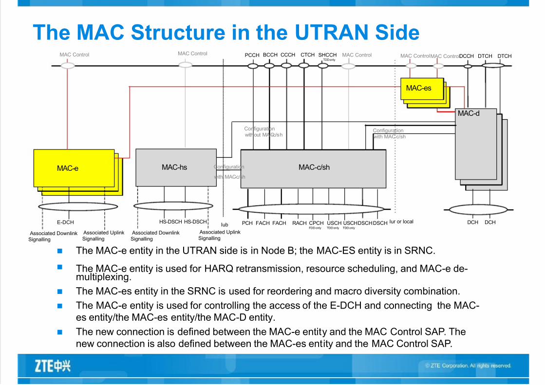
The MAC Structure in the UTRAN Side
FACH RACH
DCCH DTCHDTCH
DSCH
MAC Control
Iur or local
MAC Control
DCH DCH
MAC-d
USCHTDD only
MAC-c/sh
CPCHFDD only
CCCH CTCHBCCH SHCCHTDD only
PCCH
FACHPCH USCHTDD only
DSCH
MAC Control
HS-DSCH HS-DSCH
Associated Uplink
Signalling Associated Downlink
Signalling
MAC-hs
Configuration
without MAC-c/shConfiguration
with MAC
Configuration
with MAC-c/sh
E-DCH
Associated Uplink
Signalling Associated Downlink
Signalling
MAC Control
MAC-es
MAC-e
MAC Control
Iub
c/sh
The MAC-e entity in the UTRAN side is in Node B; the MAC-ES entity is in SRNC.
The MAC-e entity is used for HARQ retransmission, resource scheduling, and MAC-e de-multiplexing.
The MAC-es entity in the SRNC is used for reordering and macro diversity combination.
The MAC-e entity is used for controlling the access of the E-DCH and connecting the MAC-
es entity/the MAC-es entity/the MAC-D entity.
The new connection is defined between the MAC-e entity and the MAC Control SAP. The
new connection is also defined between the MAC-es entity and the MAC Control SAP.

7/30/2019 WPO-12 HSUPA Principleand Plan-45
http://slidepdf.com/reader/full/wpo-12-hsupa-principleand-plan-45 15/45
Structure and Function of the MAC-es Entity
in the UTRAN Side
MAC-es
MAC – Control
FromMAC-e inNodeB #1
To MAC-d
Disassembly
Reordering QueueDistribution
Reordering QueueDistribution
Disassembly
Reordering/Combining
Disassembly
Reordering/Combining
Reordering/Combining
FromMAC-e inNodeB #k
MAC-d flow #1 MAC-d flow #n
Queue distribution reordering entity:
Route the MAC-es PDU to the correct
reordering buffer according to the
configuration of SRNC.
Reordering entity: Reorder the received
MAC-es PDUs according to the received
TSN and Node B identifier. Macro diversity selection entity: Select
and combine the MAC-es PDU data of
Node B in the soft switchover process.
MAC-es PDC disassembling entity:
Remove the MAC-es header and
transmit MAC-d PDU to the MAC-d layer.
The following function entities are included
in the MAC-es layer in the SRNC side:

7/30/2019 WPO-12 HSUPA Principleand Plan-45
http://slidepdf.com/reader/full/wpo-12-hsupa-principleand-plan-45 16/45
Structure and Function of the MAC-es Entity
in the UTRAN Side
MAC - e
MAC –
Control
E-DCH
AssociatedDownlinkSignaling
AssociatedUplink
Signaling
MAC-d Flows
De-multiplexing
HARQ entity
E-DCHScheduling E-DCH
Control
The following functional entities are included
in MAC-e in the Node B side:
E-DCH scheduling and control entity:
Based on the scheduling request (SR)
of the UE, it allocates the resources
for the UE according to certain
regulations, generates resource order,
and notifies the UE through the
downlink signaling. De-multiplexing entity: De-multiplex
MAC-e PDU and save the de-
multiplexed SI. The E-DCH
scheduling entity makes the
scheduling according to the SI.
HARQ entity: It handles multiple stop-
and-wait HARQ processes, generates ACK/NACK, and indicates whether
the data transmitted in E-DCH is
correct. It gives out the statistic result
of the retransmission number for
reference of the scheduling of the
scheduling entity.
7/30/2019 WPO-12 HSUPA Principleand Plan-45
http://slidepdf.com/reader/full/wpo-12-hsupa-principleand-plan-45 17/45
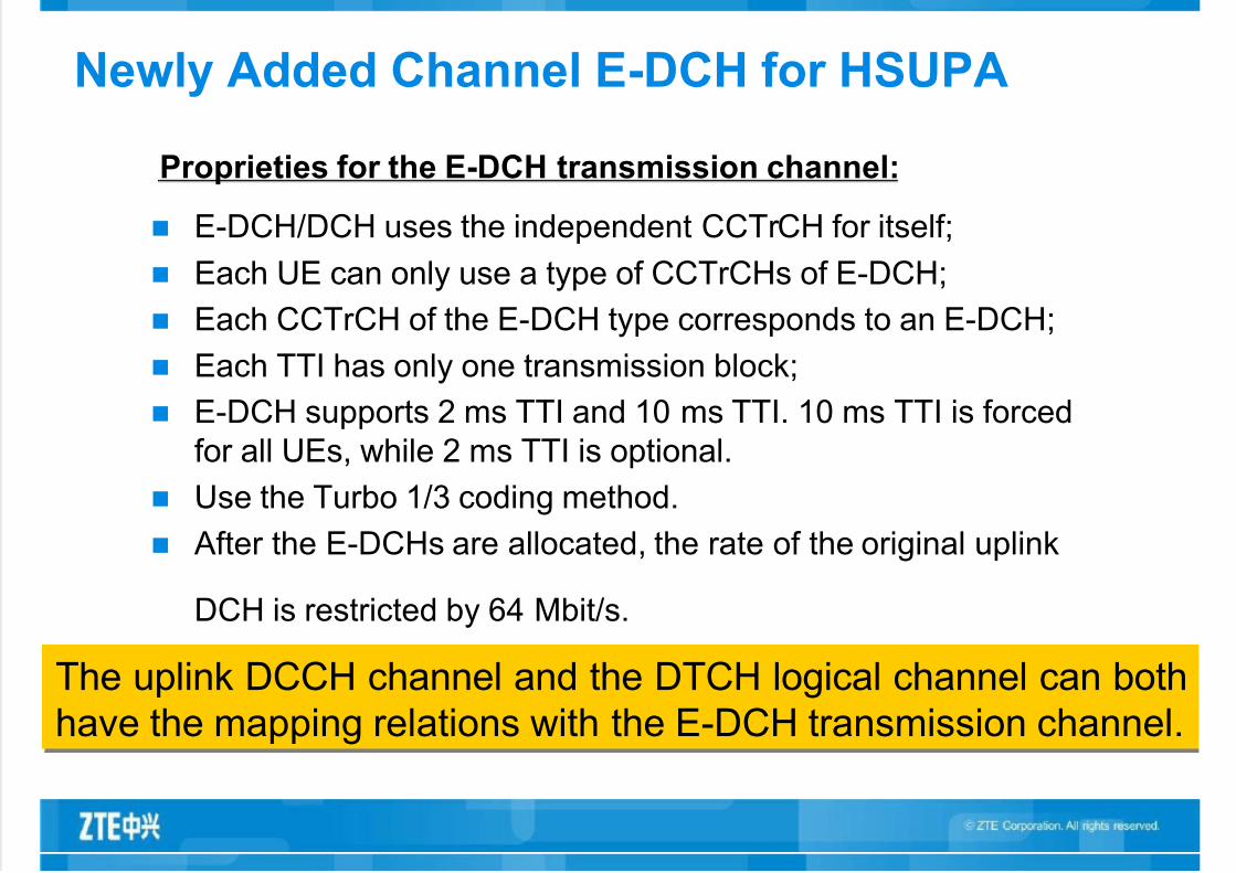
Newly Added Channel E-DCH for HSUPA
Proprieties for the E-DCH transmission channel:
E-DCH/DCH uses the independent CCTrCH for itself;
Each UE can only use a type of CCTrCHs of E-DCH;
Each CCTrCH of the E-DCH type corresponds to an E-DCH;
Each TTI has only one transmission block;
E-DCH supports 2 ms TTI and 10 ms TTI. 10 ms TTI is forced
for all UEs, while 2 ms TTI is optional.
Use the Turbo 1/3 coding method.
After the E-DCHs are allocated, the rate of the original uplink
DCH is restricted by 64 Mbit/s.
The uplink DCCH channel and the DTCH logical channel can both
have the mapping relations with the E-DCH transmission channel.
7/30/2019 WPO-12 HSUPA Principleand Plan-45
http://slidepdf.com/reader/full/wpo-12-hsupa-principleand-plan-45 18/45
Newly Added Physical Channels for HSUPA
E-DPDCH: E-DCH dedicated physical data transmission channel
(uplink);
E-DPCCH: E-DCH dedicated physical control channel (uplink);
E-HICH: E-DCH HARQ acknowledgement indicator channel
(uplink);
E-AGCH: E-DCH absolute grant channel (uplink);
E-RGCH: E-DCH relative grant channel (downlink).
Five kinds of physical channels are newly added for the ports in the air to
support quick retransmission in the physical layer, soft combination, and
Node B distributional scheduling. They support 2 ms TTI and 10 ms TTI.
7/30/2019 WPO-12 HSUPA Principleand Plan-45
http://slidepdf.com/reader/full/wpo-12-hsupa-principleand-plan-45 19/45
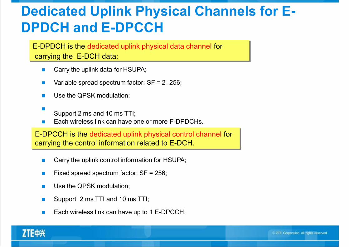
Dedicated Uplink Physical Channels for E-
DPDCH and E-DPCCH
Carry the uplink data for HSUPA;
Variable spread spectrum factor: SF = 2 –256;
Use the QPSK modulation;
Support 2 ms and 10 ms TTI;
Each wireless link can have one or more F-DPDCHs.
E-DPDCH is the dedicated uplink physical data channel for
carrying the E-DCH data:
E-DPCCH is the dedicated uplink physical control channel for
carrying the control information related to E-DCH.
Carry the uplink control information for HSUPA;
Fixed spread spectrum factor: SF = 256;
Use the QPSK modulation;
Support 2 ms TTI and 10 ms TTI;
Each wireless link can have up to 1 E-DPCCH.

7/30/2019 WPO-12 HSUPA Principleand Plan-45
http://slidepdf.com/reader/full/wpo-12-hsupa-principleand-plan-45 20/45
Public Downlink Physical Channel for E-AGCH
Slot #1 Slot #14Slot #2 Slot #iSlot #0
Tslot = 2560 chips
1 subframe = 2 ms
1 radio frame, Tf = 10 ms
E-AGCH 20 bits
Fixed spread spectrum factor SF = 256; channel rate: 30 Kbit/s.
The E-AGCH only exists in the serving E-DCH cell.
Absolute grant of E-DCH can only be transmitted in the serving E-DCH cell.
Absolute grant can be transmitted in the sub frame (2 ms TTI) or in the radio frame (10 ms TTI).
E-AGCH is the public downlink physical channel for carrying the
E-DCH absolute grant.

7/30/2019 WPO-12 HSUPA Principleand Plan-45
http://slidepdf.com/reader/full/wpo-12-hsupa-principleand-plan-45 21/45
Dedicated Downlink Physical Channel of E-RGCH
Slot #14
Tslot = 2560 chip
bi,39 bi,1 bi,0
Slot #0 Slot #1 Slot #2 Slot #i
1 radio frame, Tf = 10 ms
1 subframe = 2 ms
E-RGCH is the dedicated downlink physical channel for carrying
relative grant of E-DCH.
Fixed spread spectrum factor SF = 128.
A relative grant can be sent by 3, 12, or 15 continuous slots. Therein, the 3
continuous slots and 12 continuous slots correspond to 2 ms TTI and 10 ms TTI
separately in the serving E-DCH cell. The 15 continuous slots are used for non
serving E-DCH cell.
7/30/2019 WPO-12 HSUPA Principleand Plan-45
http://slidepdf.com/reader/full/wpo-12-hsupa-principleand-plan-45 22/45
Dedicated Downlink Physical Channel for E-HICH
Slot #14
Tslot = 2560 chip
bi,39 bi,1 bi,0
Slot #0 Slot #1 Slot #2 Slot #i
1 radio frame, Tf = 10 ms
1 subframe = 2 ms
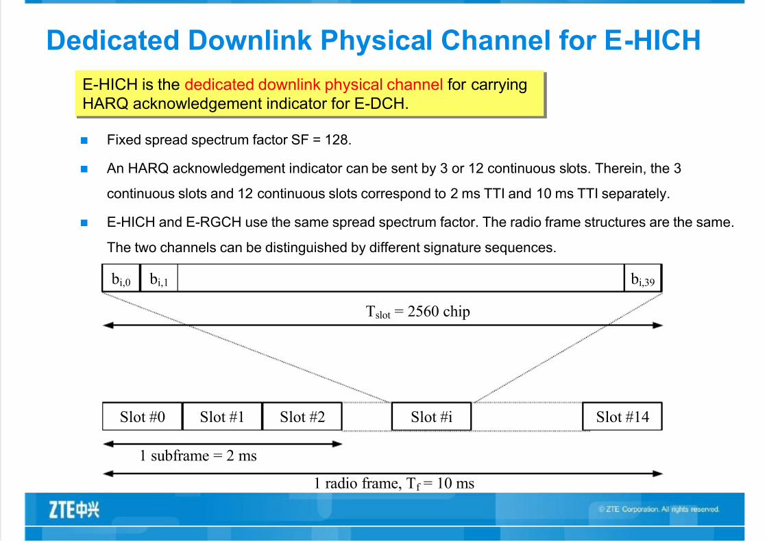
E-HICH is the dedicated downlink physical channel for carrying
HARQ acknowledgement indicator for E-DCH.
Fixed spread spectrum factor SF = 128.
An HARQ acknowledgement indicator can be sent by 3 or 12 continuous slots. Therein, the 3
continuous slots and 12 continuous slots correspond to 2 ms TTI and 10 ms TTI separately.
E-HICH and E-RGCH use the same spread spectrum factor. The radio frame structures are the same.
The two channels can be distinguished by different signature sequences.

7/30/2019 WPO-12 HSUPA Principleand Plan-45
http://slidepdf.com/reader/full/wpo-12-hsupa-principleand-plan-45 23/45
Basic Concepts
Serving E-DCH cell
It is the cell for the UE to receive the absolute grants. The UE has only
one serving E-DCH cell.
Serving E-DCH RLS or serving RLS
It is the set of cells which include the serving E-DCH cell. There is only
a serving RLS in the UE. In the serving RLS, the UE can receive and
combine a relative grant.
Non-serving E-DCH RLS or non-serving RLS
It is the set of cells which do not include of the serving E-DCH cell. The
UE can have none, one or more non-serving RLS. In the non-serving
RLS, the UE can only receive one relative grant.
E-DCH active set
It is the set of cells which use E-DCH for carrying data for the UE.
7/30/2019 WPO-12 HSUPA Principleand Plan-45
http://slidepdf.com/reader/full/wpo-12-hsupa-principleand-plan-45 24/45
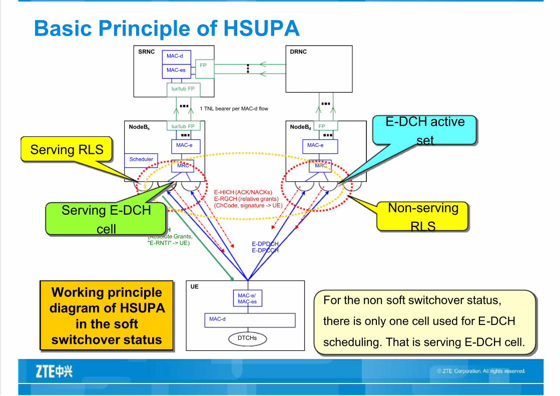
Basic Principle of HSUPASRNC DRNC
MAC-esFP
MAC-d
NodeBs Iur/Iub FP
Scheduler
MAC-e
NodeBd FP
MAC-e
UE
MAC-e/MAC-es
MAC-d
DTCHs
E-DPDCHE-DPCCH
E-AGCH
(Absolute Grants,"E-RNTI" -> UE)
serving cell
E-HICH (ACK/NACKs)E-RGCH (relative grants)(ChCode, signature -> UE)
MRC MRC
1 TNL bearer per MAC-d flow
Iur/Iub FP
Serving RLS
Non-serving
RLS
E-DCH active
set
Serving E-DCH
cell
Working principle
diagram of HSUPA
in the soft
switchover status
For the non soft switchover status,
there is only one cell used for E-DCH
scheduling. That is serving E-DCH cell.

7/30/2019 WPO-12 HSUPA Principleand Plan-45
http://slidepdf.com/reader/full/wpo-12-hsupa-principleand-plan-45 25/45
Basic Working Flow of HSUPA
The UE starts the service requests to the network side. The process is the same as that of
R99/R4.
The SRNC receives the RAB establishment request sent by CN, determines to select the
E-DCH transmission channel for the uplink according to the service propriety, and sends
the RL SETUP message to Node B. The information which RL is the E-DCH RL and which
RL is the serving E-DCH RL is indicated in the message.
When Node B makes the RL, it sends the RL establishment response to the RNC. The
response message includes the E-AGCH/E-RGCH/E-HICH scrambling code and
channelization code, and signature sequence of the E-RGCH/E-HICH. If a group of RLs
include the serving RL, Node B allocates E-RNTI for the UE, and the response message
should include the E-RNTI.
RNC sends the RB SETUP message to the UE. The message includes the E-RNTI, the
mapping relation between RB and the Mac-d flow, E-TFCS, the Mac-d flow information,the E-AGCH/E-RGCH/E-HICH code resources and signature information.
The dedicated channel of E-DCH is established as follow:
7/30/2019 WPO-12 HSUPA Principleand Plan-45
http://slidepdf.com/reader/full/wpo-12-hsupa-principleand-plan-45 26/45
Basic Working Flow of HSUPA—Continued 1
The E-DCH scheduling process is as follow:
The UE has an serving E-DCH cell, and in this cell Node B charges for the E-DCH scheduling.
The serving E-DCH cell sends the scheduling order (which is the absolute grant) to the UE
through the downlink E-AGCH. Absolute grant regulates the absolute value of the maximum
available resource of the UE. Absolute grant includes the E-RNTI and the maximum
transmission power allowed by the UE.
The serving E-DCH cell and the non-serving E-DCH cell send relative grant to the UE through
the downlink E-RGCH. The relative grant is offset (slight adjustment) of the absolute grant.
The values for it can be "UP", "HOLD" and "DOWN". "UP" means to adjust the value up;
"DOWN" means to adjust the value down; "HOLD" means there is no change to the value.
Only the serving E-DCH RLS can send the value "UP". The non-serving E-DCH RLS can only
send "HOLD" and "DOWN". The common reason for the non-serving E-DCH RLS sending
"DOWN" is that the uplink is overloaded.
7/30/2019 WPO-12 HSUPA Principleand Plan-45
http://slidepdf.com/reader/full/wpo-12-hsupa-principleand-plan-45 27/45
Basic Working Flow of HSUPA—Continued 2
The E-DCH data transmission and retransmission process are as follow:
The UE does the E-TFC selection according to the received grant information. It sends data
(including retransmission data) in the E-DPDCH. It also sends the E-TFC information, HARQ
RV information (RSN), and one happy bit. The happy bit is used for notifying the UE in Node B
side whether it is satisfied by the current allocated resources (grant). This means that whether
the UE needs higher grant.
In the E-DCH set, do the MRC combination for the E-DCH data received by different cells in
the same Node B. then hand it in for the MAC-e processing. Each UE has each MAC-E ineach Node B. Mac-e de-multiplexes Mac-e PDU to form MAC-es PDU to send to RNC. Mac-e
is also used for transmitting E-DCH scheduling information and the response ACK/NACK of
HARQ.
Each UE has a Mac-es entity in SRNC. The Mac-es entity does the macro diversity
combination for different MAC-es PDUs in Node B, reorders the queue, separates it to
different Mac-d PDUs, and transmits to Mac-d.
HARQ process: the UE transmits HARQ RV ( reordering sequence number: RSN) through theuplink E-DPCCH. Node B transmits ACH/NACH through the downlink E-HICH.

7/30/2019 WPO-12 HSUPA Principleand Plan-45
http://slidepdf.com/reader/full/wpo-12-hsupa-principleand-plan-45 28/45
Flow Example for Generation of Physical
Channel of HSUPA
E-DPDCH fixed reference channel 3 (FRC3)
Information Bit Payload NINF = 8100
CRC Addition
3 x (NINF+24)/2 = 12186
Code Block Segmentation (8100+24)/2 = 4062
Turbo Encoding (R=1/3)
RV Selection 11520
Physical Channel Segmentation 3840
24NINF = 8100
12
(8100+24)/2 = 4062
3840 1920 1920
3 x (NINF+24)/2 = 12186 12
SF=4SF=4SF=2SF=2
2ms sub frame 2ms sub frame

7/30/2019 WPO-12 HSUPA Principleand Plan-45
http://slidepdf.com/reader/full/wpo-12-hsupa-principleand-plan-45 29/45
HSUPA Brought in Requirements
Basic Principle of HSUPA
Key Technologies of HSUPA
HSUPA Plan
Content

7/30/2019 WPO-12 HSUPA Principleand Plan-45
http://slidepdf.com/reader/full/wpo-12-hsupa-principleand-plan-45 30/45
HARQ Technology
Hybrid automatic repeat quest (HARQ) is a kind of error correcting
technology. Hybrid means the hybrid of the forward error correction(FEC) and auto repeat request (ARQ).
The HARQ functions are in the MAC-e entities of Node B and the UE
separately.
Quick HARQ basic principle of HSUPA is to add the HARQ functional
entity in Node B. if not correctly received, Node B will request the UE
to retransmit the uplink packet data.
In the uplink, HARQ uses N stop-and-wait (NSAW) for the HARQ
protocol.
In HSUPA, the HARQ process number has the fixed corresponding
relation with the TTI. 10 ms TTI corresponds to 4 HARQ processes,
while 2 ms TTI corresponds to 8 HARQ processes.
The main function of HARQ is to reduce the transmission delay
and improve the UE/system throughput rate.

7/30/2019 WPO-12 HSUPA Principleand Plan-45
http://slidepdf.com/reader/full/wpo-12-hsupa-principleand-plan-45 31/45
HARQ—HARQ Retransmission Combination Method
Forwarding error correction of the uplink HARQ can be divided to
chase combining (CC) and incremental redundancy (IR). The information that transmitted in the CC mode is total the same as
that of the original information. Combine the retransmitted informationin maximum before the UE decodes it. Then the UE decodes theinformation. The process is done this way to improve the decodinggain.
The IR retransmission supports the following two kinds:
The one is to transmit the redundancy information which is totallydifferent from the previously transmitted information. Theinformation can only be decoded by combining with the firsttransmitted information.
The other one is to transmit the redundancy information which istotally different from the previously transmitted information. Theinformation can be decoded by itself. Before each HARQretransmission, improve the capability of forwarding error correction before decoding by giving out the redundancy with fixedincrement.
Node B can use different methods to combine multiple retransmissions in a single packet, to reduce the
received Ec/No in each transmission requirement. Through the HARQ technology, HSUPA can
effectively improve the data transmission rate and reduce the delay.

7/30/2019 WPO-12 HSUPA Principleand Plan-45
http://slidepdf.com/reader/full/wpo-12-hsupa-principleand-plan-45 32/45
HARQ—Retransmission Comparison of
HARQ of HSUPA and RLC of R99
The target BLER of the first transmission is much higher by using the HARQtechnology. Compare to the transmission of the RLC level, the delay of thepacket received incorrectly in the HARQ retransmission is reduced obviously.
Much higher BLER target can decrease the UE transmission power requiredwhen data with certain rate is transmitted. For the cell with the same load, thequick HARQ technology can expand the capacity of the cell.
When the data rate is fixed, reducing the energy of each bit can help enlargingthe coverage area.
7/30/2019 WPO-12 HSUPA Principleand Plan-45
http://slidepdf.com/reader/full/wpo-12-hsupa-principleand-plan-45 33/45
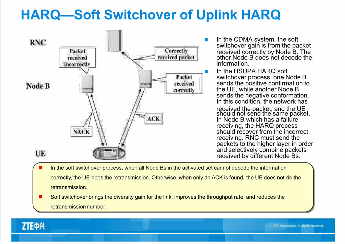
HARQ—Soft Switchover of Uplink HARQ
In the CDMA system, the softswitchover gain is from the packetreceived correctly by Node B. Theother Node B does not decode theinformation.
In the HSUPA HARQ softswitchover process, one Node Bsends the positive confirmation tothe UE, while another Node Bsends the negative conformation.In this condition, the network hasreceived the packet, and the UEshould not send the same packet.In Node B which has a failurereceiving, the HARQ processshould recover from the incorrectreceiving. RNC must send thepackets to the higher layer in order and selectively combine packetsreceived by different Node Bs.
In the soft switchover process, when all Node Bs in the activated set cannot decode the information
correctly, the UE does the retransmission. Otherwise, when only an ACK is found, the UE does not do the
retransmission.
Soft switchover brings the diversity gain for the link, improves the throughput rate, and reduces the
retransmission number.

7/30/2019 WPO-12 HSUPA Principleand Plan-45
http://slidepdf.com/reader/full/wpo-12-hsupa-principleand-plan-45 34/45
Quick Packet Scheduling Technology Based
on Node B
In R99/R4/R5, the uplink packetscheduling function is in RNC.
In HSUPA, the scheduling function is in
Node B, and the scheduling period is
short (2 ms). In this condition, the new
scheduling policy can be realized and
the capacity of the port in the air in
uplink can be used effectively.
Packet scheduling controlled by RNC brings in certain delay. It can not give out the
channel change information in current time, so the quick link adaption and quickpacket scheduling cannot be done.
In the HSUPA system, the packet scheduling entity of Node B can use measured
information in real time, internal statistic information, and the information reported
by the UE for scheduling. The traditional delay can be reduced by using channel
conditions and fading characteristics of different users.

7/30/2019 WPO-12 HSUPA Principleand Plan-45
http://slidepdf.com/reader/full/wpo-12-hsupa-principleand-plan-45 35/45
Basic Principle of HSUPA Scheduler —Differences of
Scheduling Algorithms of HSUPA and R5
1) HSDPA is the shared downlink HS-DCH resource. The UE
multiplexes the power, code channel, and time for HS-DCH. The UEreports the CQI to Node B according to wireless channel quality. NodeB scheduler does the scheduling according to the CQI, service type,and service traffic of each UE. The throughput rate of the cell and thescheduling fairness are important for estimating the schedulingperformance. The three scheduling algorithms can generate several
algorithms with fair scale. These algorithms can be usedindependently or used in hybrid for different occasions.
2) The UE in the HSUPA cell has its own code channel and power resource, which there is no exclusivity in. The uplink interference limitof the cell limits the capacity of the uplink of the cell. For HSUPA, theUE, the UE priority, and the uplink channel quality are main factors for the scheduling algorithm. When the real time service has the high
priority or when the UE obtains much scheduling resources (uplinktransmission power or rate), more uplink capacity can be occupied.Therefore, the scheduling algorithm of HSUPA can be divided to thepriority scheduling and weighted scheduling based on priority C/I(while doing the priority scheduling, the fairness of different services of the UE must be considered).

7/30/2019 WPO-12 HSUPA Principleand Plan-45
http://slidepdf.com/reader/full/wpo-12-hsupa-principleand-plan-45 36/45
Basic Principle of HSUPA Scheduler —Node B
Scheduler Function Node B scheduler of HSUPA transmits absolute grant (AG) and
relative grant (RG) to the UE according to service requirement of eachUE in the cell, uplink interference degree of the cell, and loadprocessing ability of Node B. The UE sends the uplink servicerate/power in the range of the AG and adjusts the rate/power up or down according to the RG.
The service scheduling of the UE can be divided to non-schedulinggrants and scheduling grants. Therein, Non-scheduling grants are
configured to the UE by RNC, to transmit the GBR service and theSRB service. Node B scheduler can not control the scheduling of theservice of the part. Scheduling grants is the main object for Node Bscheduling of the UE service.
Input information of Node B scheduler:
Request information of the UE for service scheduling;
ROT threshold configured by the network;
Interference condition in uplink in each cell.
Output information:
For AG/RG of the UE in the serving cell and RG of the UE in the non-serving cell;
Current interference level of the cell and load condition of Node B.

7/30/2019 WPO-12 HSUPA Principleand Plan-45
http://slidepdf.com/reader/full/wpo-12-hsupa-principleand-plan-45 37/45
Basic Principle of HSUPA Scheduler —
Scheduling Based on Priority
The service scheduled by the UE can be divided to non-
scheduling grants and scheduling grants. Scheduler of Node Bmainly control the service scheduling of scheduling grants.
The scheduling grants are triggered according to servicerequirements of the UE (the service can also be triggered bythe network). The requirement of the service of the UE isdescribed by QoS parameters. It is realized by limiting the
priority of logical channels and the size of transmission blockregulated in 3GPP 25.309. The contents that UE sends theservice scheduling request to Node B include: ID of logicalchannel with highest priority which needs to transmit data,occupation status of buffer of the logical channel (or occupationstatus of general buffer of the UE), and remaining power rate of the UE. Then, Node B scheduler orders these requests
according to the priority requirement in each UE schedulingrequest. It also transmits AG to each UE according to the UEremaining power and load condition of Node B. By consideringthe fairness, the user who has a large occupation of the UEbuffer or has a long time occupation can improve the AG or theRG properly.

7/30/2019 WPO-12 HSUPA Principleand Plan-45
http://slidepdf.com/reader/full/wpo-12-hsupa-principleand-plan-45 38/45
Basic Principle of HSUPA Scheduler —Load
Control of HSUPA
RoT is the most important uplink wireless resource
in the HSUPA system. Only when the RoT is
controlled in a higher range and the rate which is
over a certain threshold is controlled in a certain
number (0.01), the uplink interference margin can be
fully used to meet the requirement of the uplinkservice traffic for E-DCH.

7/30/2019 WPO-12 HSUPA Principleand Plan-45
http://slidepdf.com/reader/full/wpo-12-hsupa-principleand-plan-45 39/45
Basic Principle of HSUPA Scheduler —
Consideration for Scheduling Different Kinds of UE
1) Low rate for real time service ensures the highest priority for bit rate service
and SRB in the system. Use non-scheduled transmission for the real timeservice with low bit rate. The service of this part is not scheduled by Node B,but the scheduler still needs to consider the cell load and interferencegenerated by the service of this part.
2) Ensure the real time service of bit rate, such as gaming. For real timeservice which does not ensure the bit rate, the most important indication isdelay of the service. The delay is required no larger than 100 –250 ms. Thiskind of services has the burst characteristic of the packet service. It also asks
that the burst packet service must be transmitted in short time as soon aspossible.
3) Ensure the non real time service of near real time (NRT) service of the rate,such as streaming. The system is required to provide a lowest bit rate for theUE. The delay can be 1 –10 s. This service scheduling of the kind is put after the real time scheduling, for it has a smaller opportunity.
4) Ensure the background service, such as FTP. When scheduling of other service is satisfied in the cell, and there is margin in the load of the cell, the
service which has a low requirement to the delay and rate can be scheduled.For the scheduling of the kind of the service, you can refer to packet servicescheduling mechanism. The proportional fair algorithm is the best choice whenthe throughput rate of the cell and the fairness for the UE to obtain thetransmission opportunity are considered.

7/30/2019 WPO-12 HSUPA Principleand Plan-45
http://slidepdf.com/reader/full/wpo-12-hsupa-principleand-plan-45 40/45
2 ms TTI
HSUPA brings in the optional short 2 ms TTI in uplink, to reduce the HARQ retransmissiondelay.
When each TTI has the same amount of data, the power energy transmitted in 2 ms maybe less than that in 10 ms. The interleaving gain is decreased. To realize the normal workof the border area of the cell, 10 ms TTI is used as regulated.
When there is no other limits, such as there is no link coverage, we can see that 2 ms TTIcan expand the corresponding system capacity. When the wireless environment is good, 2ms TTI can bring the peak rate.
E-DCHType
SFModulation
TTI
Size of maximum
transmission block (bit)
(10 ms/2 ms)
Data rate (10 ms/2 ms)
Category 1 1 SF4 Only 10 ms 7110 0.71 Mbit/s
Category 2 2 SF4 10 ms and 2 ms 14484/27981.45 Mbit/s
/1.42 Mbit/s
Category 3 2 SF4 Only 10 ms 14484 1.45 Mbit/s
Category 4 2 SF2 10 ms and 2 ms 20000/5772 2 Mbit/s/2.9 Mbit/s
Category 5 2 SF2 Only 10 ms 20000 2 Mbit/s
Category 62 SF2 + 2
SF410 ms and 2 ms 20000/11484 2 Mbit/s/5.76 Mbit/s
7/30/2019 WPO-12 HSUPA Principleand Plan-45
http://slidepdf.com/reader/full/wpo-12-hsupa-principleand-plan-45 41/45
HSUPA Brought in Requirements
Basic Principle of HSUPA
Key Technologies of HSUPA
HSUPA Plan
Content

7/30/2019 WPO-12 HSUPA Principleand Plan-45
http://slidepdf.com/reader/full/wpo-12-hsupa-principleand-plan-45 42/45
Link Budget
Link budget is the precondition for coverage plan. The
coverage radius of the cell in the broadcasting mode can beobtained by calculating the maximum loss allowed by theservice, to make sure the base station size that satisfies thecoverage condition.
In common condition, the link budget is done in uplink (frommobile station to base station) and in downlink (from basestation to mobile station), to realize the balance between uplinkand downlink.
Commonly, the coverage plan makes the budget based on thecalculation when the phone achieves its maximum coverageradius (this is the uplink budge). For there are many unstable
factors affecting the coverage radius (such as the number of connected users, user distribution, user rate, and so on), it isvery difficult for calculation. In common condition, the power of the base station satisfies the coverage requirement. Thismeans that the uplink of the coverage area is limited.

7/30/2019 WPO-12 HSUPA Principleand Plan-45
http://slidepdf.com/reader/full/wpo-12-hsupa-principleand-plan-45 43/45
HSUPA Coverage
For different channel environments, different
demodulation performances may cause differences
of the radius. You can see that, when the throughput
rate of the border area of the coverage of HSUPA is
64 Kbit/s, the rate of the service radius shrinks 20%
higher than that of R99; when the throughput rate of the border area of the coverage of HSUPA is 600
Kbit/s, the rate of the service radius shrinks 40%
higher than that for R99.

7/30/2019 WPO-12 HSUPA Principleand Plan-45
http://slidepdf.com/reader/full/wpo-12-hsupa-principleand-plan-45 44/45
Capacity Estimation
The capacity estimation of HSUPA can be obtained
by using the Campbell algorithm.
In real operation, the network size simulation result
for HSUPA throughput rate can be calculated, to
quickly get the brief resource division and network
size.
It is determined according to the real traffic condition
in the network plan of capacity expansion.
7/30/2019 WPO-12 HSUPA Principleand Plan-45
http://slidepdf.com/reader/full/wpo-12-hsupa-principleand-plan-45 45/45