working principles of solar and other energy conversion cells
TRANSCRIPT

3
ice | science
Nanomaterials and EnergyVolume 2 Issue NME1
Working principles of solar and other energy conversion cellsLiu, Wang, Wang and Yang
Pages 3–10 http://dx.doi.org/10.1680/nme.12.00024Themed Issue Research PaperReceived 24/07/2012 Accepted 22/08/2012Published online 05/09/2012Keywords: battery/energy conversion/fuel cell/photoelectrochemical cell/photovoltaics/thermoelectric
ICE Publishing: All rights reserved
1. IntroductionEnergy, which can exist in a variety of forms, describes the capacity or power of a system to do work. There are many energy resources, including nonrenewable and renewable ones. Except for nuclear, tidal and geothermal energies, all resources of energy ultimately come from the sun.1 Energy conversion is the process of transform-ing one form of energy to another, which complies by the laws of thermodynamics.2 Correspondingly, there exit many different energy conversion devices that can convert energy from different energy sources into useful forms (in particular, electricity and heat) to meet our needs. Among those energy conversion devices are solar photovoltaic (PV), thermoelectric, electrochemical and pho-toelectrochemical (PEC) cells that have been main research areas particularly in recent years when people realized that renewable energy is the key to creating a clean energy future for the world.3 In the past, these cells have been developed independently with each other. For example, fuel and solar cells have been traditionally regarded to belong to different disciplines of electrochemistry and semiconductor, respectively, in spite of the facts that both the first demonstration of a fuel cell done by William Grove and the first PV
effect observed by Edmund Becquerel are in the same year of 1839, and both of them are electricity-producing devices.4,5 In this review article, however, the authors showed that there are close connec-tions between the working principles of solar PV and other energy conversion cells, which may provide more insights in designing better energy conversion devices.
2. Different energy conversion paths and a simple picture of energy conversion
As the sun is the ultimate energy resource and electricity is the most versatile form of energy,6 the authors focussed mainly on different energy conversion paths from solar energy to electrical energy (Figure 1). In nature, solar energy is converted into chemi-cal energy and stored in as biomass by plants through the process of photosynthesis (the artificial photosynthesis with PEC cells is to be discussed later).7 The conventional conversion of the chemi-cal energy of a fuel into electricity is currently based mainly on the application of heat engines, where chemical energy is first released as heat that is then converted into mechanical and finally
Working principles of solar and other energy conversion cells
Fude Liu PhD*Department of Mechanical Engineering, The University of Hong Kong, Hong Kong, China
Wentao Wang MScDepartment of Mechanical Engineering, The University of Hong Kong, Hong Kong, China
Lei Wang MScDepartment of Mechanical Engineering, The University of Hong Kong, Hong Kong, China Guandong Yang MScDepartment of Mechanical Engineering, The University of Hong Kong, Hong Kong, China
Renewable energy is the key to creating a clean energy future for the world. Energy conversion cells play important
roles in realizing this goal. In this review article, the authors addressed the issues regarding energy conversion cells in
a fresh and broad perspective. The authors checked different energy conversion paths from solar energy to electrical
energy and showed a simple picture of energy conversion. The authors then went through the working principles of
solar cells in terms of charge carrier generation, separation and transport/collection. The comparison between differ-
ent energy conversion cells, including solar, thermoelectric, electrochemical and photoelectrochemical cells by explor-
ing the working principles of each kind of these cells was studied. It was shown that the working principles behind
these cells are quite similar, following a simple energy conversion picture. The aim of this article is to explore the close
connections between different energy conversion cells and the essence behind.
2
3
4
1
*Corresponding author e-mail address: [email protected]
1 2 3 4

Nanomaterials and EnergyVolume 2 Issue NME1
Working principles of solar and other energy conversion cellsLiu, Wang, Wang and Yang
4
into electrical energy. According to the Carnot’s theorem that is a result of the second law of thermodynamics, the energy conversion efficiency of heat engines is low. An electrochemical cell (fuel cell or battery cell), however, can directly convert the chemical energy of a fuel into electricity. Therefore, electrochemical cells create electricity chemically, rather than by combustion, at a higher effi-ciency at least in principle, because they are not subjected to ther-modynamic laws that limit a conventional power plant.8 In addition, waste heat from some electrochemical cells can also be harnessed, boosting the system efficiency still further. Alternatively, heat can be produced from solar energy with solar collectors, such as para-bolic troughs/dishes and linear Fresnel reflectors for electricity production, that is, concentrating solar power.9 In addition, heat can be directly converted into electrical energy with thermoelec-tric cells. Because of the heating (or uneven heating for the case of wind energy, to be more accurate) of solar radiation on the fluid (air or water), air or water flows from a higher energy level to a lower energy level so that wind or hydro energy is obtained that can be harnessed to produce electrical energy with wind or water
turbines.3 With even fewer steps, a solar cell converts solar energy directly into electricity using the PV effect.10
Before discussing in detail on each kind of these cells, it may be helpful to get some perspective on them with a simple picture of energy conversion (Figure 2). There are a few key things for a working energy conversion device, explained as follows:
1. Key components: At least two different energy levels with available energy states for mobile carriers and a path loop for carriers to flow through.
2. Carrier pumping: Carriers must be pumped from a lower energy level to a higher energy level with the energy input, which can be done either in situ or ex situ.
3. Carrier separation: Carriers at the higher energy level have to be physically separated from their corresponding empty states at the lower energy level inside the cell to reduce recombination. Otherwise, the energy leakage is high, and significant amount of energy is wasted inside the cell.
4. Carrier transport: The carrier transport must be as smooth as possible with minimum resistance except at the load to achieve high energy conversion efficiency.
5. Energy conversion efficiency (η) = (Energy output) / (energy input). Power output (P) = current × potential = I × V. The energy not converted into work done on the load as energy output is often dissipated as waste heat.
In fact, the above picture can be put in the more basic nonequilib-rium theory,11 which states that under nonequilibrium condition, there is always a current of something trying to reduce a gradient in something else that is the actual cause of the nonequilibrium such that equilibrium can be re-established. As far as the charged
Figure 1. Different energy conversion paths from solar energy to
electrical energy.
Solar energy
Electrical energy
Chemical energy
Mechanicalenergy
Heat Wind or hydro
Pho
tosy
nth
esis
or
PEC
cel
lB
urn
ing
Sola
r co
llect
or
Ther
mo
elec
tric
cel
l
Turb
ine
Hea
tin
g
Sola
r ce
ll
Eng
ine
Gen
erat
or
Elec
tro
chem
ical
cel
l
Figure 2. A simple picture of energy conversion.
Waste heat
Energy carrier(higher level)
Energy carrier(lower level)
Reservoir #2
LoadLeakagePump
Ecarrier
Reservoir #1
Energyoutput
Energyinput

Nanomaterials and EnergyVolume 2 Issue NME1
Working principles of solar and other energy conversion cellsLiu, Wang, Wang and Yang
5
particles such as electrons are concerned, a gradient in the electrical potential causes drift currents and a gradient in a chemical poten-tial (which is a function of concentration and temperature) causes diffusion currents.12 The total driving force for electrons is then the gradient of the so-called electrochemical potential (the sum of electrical potential and chemical potential).
In the following discussion, the authors focused on solar cells, thermoelectric cells, batteries, fuel cells and PEC cells, because these cells have been the active and main research areas in recent years as aforementioned. It is also important to note that all these cells produce direct current (DC) due to the flow of electrons. So it is important to know the energy levels of electrons in different mediums in these cells.
3. Solar cellsPV is a technique of directly converting solar radiation into elec-tricity using semiconductors that exhibit the PV effect. As solar energy is the most abundant energy resource, it is almost guaranteed to be an indispensable part of the energy system. Compared with other energy conversion paths from solar energy to electricity, PV has a higher overall efficiency. In addition, PV is the only renew-able energy source that can be used everywhere. So far, there have been many kinds of solar cells. Traditionally, solar cells have been classified according to the materials used in absorber layers, that is, essentially charge generation.13 Here, the authors made a slightly dif-ferent approach, which may provide more insights on the working principles of solar cells. On the basis of junctions applied, these cells can be classified into three major groups, that is, inorganic p-n junc-tion–based solar cells, organic e-donor/e-acceptor junction–based solar cells and hybrid junction–based solar cells (Figure 3). In addi-tion, hybrid junction-based solar cells can be further divided into two subgroups: dye-sensitized solar cells and other hybrids. New concept
solar cells, in particular those based on nanostructures and quantum confinement, have been investigated also in recent years.14,15
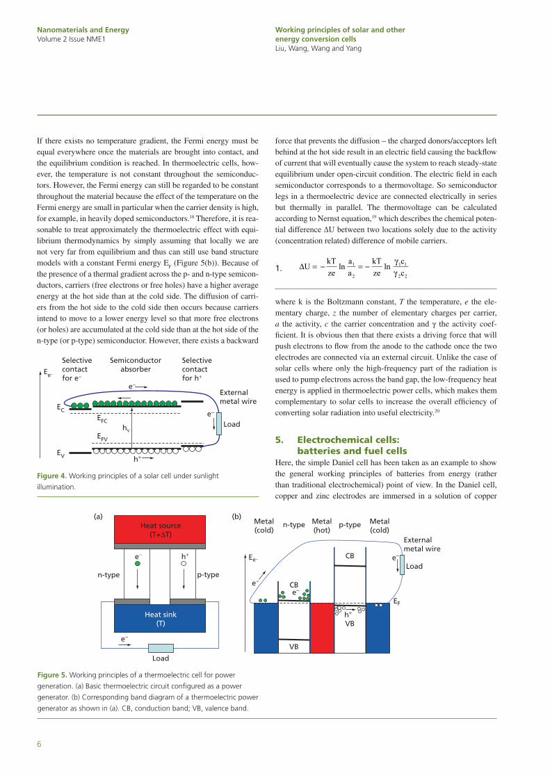
Figure 4 illustrates the basic working principles of a solar cell under sunlight illumination. There are three key steps for a work-ing solar cell. First of all, there is charge carrier generation (or light pumping): Electrons in the semiconductor (with right band gap E
g) absorber are pumped from the valence band (VB) to the
conduction band (CB) in the presence of sunlight. Second, there is charge carrier separation: Electrons in the CB and holes in the VB have to move in different directions so that they are physi-cally separated from each other to minimize direct recombination inside the device, which is often realized with selective contacts. Finally, there is charge carrier transport/collection: Carrier trans-port through the absorber, selective contacts, metal wire and inter-faces between them has to be smooth, that is, the resistance should be minimized, which requires that suitable materials be selected with the right energy band alignment between them and less defect states. Overall, electrons flow along the path loop, absorbing solar energy when pumped from the lower level VB to the higher level CB and releasing their energy by doing work on the load, in a simi-lar fashion as the hydrologic cycle in hydro power.16
4. Thermoelectric cellsIn this section, the discussion is limited to the thermoelectric cells for power generation only; other thermoelectric devices based on different thermoelectric effects will not be considered here. This kind of cell is applied to convert heat energy directly into electri-cal energy based on the Seebeck effect.17 A typical thermoelectric device essentially consists of metal–semiconductor junctions as the one shown in Figure 5(a). The device is configured as a power gen-erator, and it creates a voltage when there is a temperature differ-ence ΔT between the two sides of semiconductors.
Figure 3. Classification of solar cells based on junctions applied.
CIGS, copper indium gallium (di)selenide; CZTS, copper zinc tin
sulfide; P3HT, poly(3-hexylthiophene); PCBM, [6,6]-phenyl
C61-butyric acid methylester.
Other hybrid solar cells: inorganicnanostructure + organic matrix...
Dye sensitized solar cells
Hybridjunction
p-n junctionInorganic semiconductor solar cells:Si, GaAs, CdTc, CIGS, CZTS...
Solar cellsOrganic semiconductor solar cells:P3HT/PCBM
e-donor/e-acceptorjunction
Nanomaterials and EnergyVolume 2 Issue NME1
Working principles of solar and other energy conversion cellsLiu, Wang, Wang and Yang
6
If there exists no temperature gradient, the Fermi energy must be equal everywhere once the materials are brought into contact, and the equilibrium condition is reached. In thermoelectric cells, how-ever, the temperature is not constant throughout the semiconduc-tors. However, the Fermi energy can still be regarded to be constant throughout the material because the effect of the temperature on the Fermi energy are small in particular when the carrier density is high, for example, in heavily doped semiconductors.18 Therefore, it is rea-sonable to treat approximately the thermoelectric effect with equi-librium thermodynamics by simply assuming that locally we are not very far from equilibrium and thus can still use band structure models with a constant Fermi energy E
F (Figure 5(b)). Because of
the presence of a thermal gradient across the p- and n-type semicon-ductors, carriers (free electrons or free holes) have a higher average energy at the hot side than at the cold side. The diffusion of carri-ers from the hot side to the cold side then occurs because carriers intend to move to a lower energy level so that more free electrons (or holes) are accumulated at the cold side than at the hot side of the n-type (or p-type) semiconductor. However, there exists a backward
force that prevents the diffusion – the charged donors/acceptors left behind at the hot side result in an electric field causing the backflow of current that will eventually cause the system to reach steady-state equilibrium under open-circuit condition. The electric field in each semiconductor corresponds to a thermovoltage. So semiconductor legs in a thermoelectric device are connected electrically in series but thermally in parallel. The thermovoltage can be calculated according to Nernst equation,19 which describes the chemical poten-tial difference ΔU between two locations solely due to the activity (concentration related) difference of mobile carriers.
1.
∆U kTze
aa
kTze
cc
= − = −ln ln1
2
1 1
2 2
γγ
where k is the Boltzmann constant, T the temperature, e the ele-mentary charge, z the number of elementary charges per carrier, a the activity, c the carrier concentration and γ the activity coef-ficient. It is obvious then that there exists a driving force that will push electrons to flow from the anode to the cathode once the two electrodes are connected via an external circuit. Unlike the case of solar cells where only the high-frequency part of the radiation is used to pump electrons across the band gap, the low-frequency heat energy is applied in thermoelectric power cells, which makes them complementary to solar cells to increase the overall efficiency of converting solar radiation into useful electricity.20
5. Electrochemical cells: batteries and fuel cells
Here, the simple Daniel cell has been taken as an example to show the general working principles of batteries from energy (rather than traditional electrochemical) point of view. In the Daniel cell, copper and zinc electrodes are immersed in a solution of copper
Figure 4. Working principles of a solar cell under sunlight
illumination.
Ee−
EV
EC
Selectivecontactfor e−
Selectivecontactfor h+
Externalmetal wire
Load
Semiconductorabsorber
EFV
EFChν
h+
e−
e−
Figure 5. Working principles of a thermoelectric cell for power
generation. (a) Basic thermoelectric circuit configured as a power
generator. (b) Corresponding band diagram of a thermoelectric power
generator as shown in (a). CB, conduction band; VB, valence band.
Heat source(T+∆T)
Heat sink(T)
Load
n-type p-type
e−
e−
h+
(a) (b)p-typen-type
CB
CB
VB
VB
Metal(cold)
Metal(hot)
Metal(cold)
Externalmetal wire
Load
e−
e−Ee−
EF
e−
h+

Nanomaterials and EnergyVolume 2 Issue NME1
Working principles of solar and other energy conversion cellsLiu, Wang, Wang and Yang
7
(II) sulfate and zinc sulfate, respectively, and a salt bridge is often used to connect the two half cells to help maintain charge neutrality (Figure 6(a)). Electron-transfer reactions are oxidation and reduction at the anode and cathode, respectively. Taking the standard hydro-gen electrode (SHE) as the energy reference point (0 V), the stand-ard electrode reduction potentials can be considered to be −0·76 and 0·34 V,21 respectively, for the following two reduction reactions:
2. Zn e Zn2 2+ −+ →
3. Cu e Cu2 2+ −+ →
Therefore, the difference between the two reduction potentials as the standard electromotive force (EMF) for the cell ( 0
cellE∆ ) can be considered as follows:
4. ∆E E · Vcell cathode anode0 0 0 0 34 0 76 110= − = − − =· ·( )
Considering the above situation in energy space, the working princi-ples of the Daniel cell in a straightforward way are shown in Figure 6(b). Compared with Figure 4, the net results are quite similar in both a solar cell and a battery cell, that is, electrons are at a higher energy level at the anode side than their corresponding empty states (i.e., holes) at the cathode side, and they intend to flow to the lower energy level via the external circuit. Of course, there are some differences between a battery cell and a solar cell. For example, there are no chemical reaction and ion transport involved in the latter (except for dye-sensitized solar cells where a redox electrolyte has been applied for charge transport),22,23 and a solar cell is essentially a current source
while a battery cell is a voltage source as pointed out by Nelson.5 In addition, the authors considered the standard condition for a work-ing battery cell. The real situation to calculate the EMF is more complicated due to the possible variations in temperature, pressure, chemical activity and so forth.24 However, the authors think that the complication will not blur the clear connection between the working principles of these two kinds of energy conversion cells.
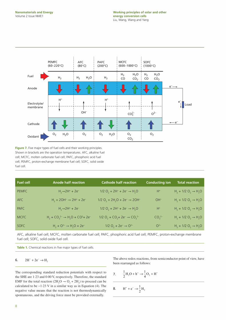
A fuel cell essentially works in a very similar way as a battery in which both convert chemical energy into electrical energy, produce DC and use electrolytes to conduct ions (Figure 6 and Figure 7). The similarity can be further verified by comparing the chemical reactions in the Daniel cell with those in the five major types of fuel cells shown in Table 1. However, there are differences between them mainly in fuel supply. A battery is a closed system with a fixed amount of chemical energy stored in the reactants within it while a fuel cell will keep producing electricity as long as fuel is supplied externally, that is, fuel cell reactions do not degrade over time.25
6. PEC cellsHydrogen (H
2) is a clean noncarbon fuel, and as aforementioned,
the sun is the most abundant energy resource. The energy issue would be greatly alleviated if H
2 could be produced by directly
splitting water using solar energy with affordable cells.26 Water splitting to produce H
2 can be traditionally realized with electroly-
sis, where the decomposition of water (H2O) into oxygen (O
2) and
hydrogen (H2) can occur when DC is connected to the two inert
electrodes immersed in the water (Figure 8(a)). Half reactions at the anode and cathode, respectively, are as follows:
5.
H O O H e2 → + ++ −12
2 22
Figure 6. Working principles of a simple battery cell. (a) Daniel cell.
(b) Working principles of a Daniel cell as shown in (a) from energy
point of view. The red arrow highlights the potential reference point:
standard hydrogen electrode.
e−
Zn2+ Cu2+
ZnSO4(aq)
CuSO4(aq)
Cu(cathode)
Zn(anode)
Zn → Zn2+ + 2e− Cu2 + 2e− → Cu
e−Load
Load
Salt bridge
Anion Catione−
h+
e−
e−
Cathode
Externalmetal wide
Anode
Anion
Cation
SHE
Saltbridge
Electrolyte
Zn2+/Zn
Cu2+/Cu
(0·34)
(–0·76)
∆E(1·10)
Zn2+
Cu2+
Ee−
(eV)−0·8
−0·6
−0·4
−0·2
0·2
0·4
0
−
+
(a) (b)
Nanomaterials and EnergyVolume 2 Issue NME1
Working principles of solar and other energy conversion cellsLiu, Wang, Wang and Yang
8
6. 2 2H e H+2+ →−
The corresponding standard reduction potentials with respect to the SHE are 1·23 and 0·00 V, respectively. Therefore, the standard EMF for the total reaction (2H
2O → O
2 + 2H
2) to proceed can be
calculated to be −1·23 V in a similar way as in Equation (4). The negative value means that the reaction is not thermodynamically spontaneous, and the driving force must be provided externally.
The above redox reactions, from semiconductor point of view, have been rearranged as follows:
7.
12
14 2H O h O H2
++ → ++
8.
H e H+ −+ →12 2
Figure 7. Five major types of fuel cells and their working principles.
Shown in brackets are the operation temperatures. AFC, alkaline fuel
cell; MCFC, molten carbonate fuel cell; PAFC, phosphoric acid fuel
cell; PEMFC, proton-exchange membrane fuel cell; SOFC, solid oxide
fuel cell.
e−
Load
AFC(80°C)
PAFC(200°C)
MCFC(600−1000°C)
SOFC(1000°C)
Fuel
Oxidant
H2
H2O H2OO2 O2 O2
CO2
O2 O2
H+ H+
OH−CO3
2− O2−
Anode
Cathode
Electrolyte/membrane
e−
e−
H2 H2O H2
PEMFC(60−220°C)
H2OCO2
H2
COH2
COH2OCO2
Fuel cell Anode half reaction Cathode half reaction Conducting ion Total reaction
PEMFC H2→2H+ + 2e− 1/2 O2 + 2H− + 2e− → H2O H+ H2 + 1/2 O2 → H2O
AFC H2 + 2OH− → 2H+ + 2e− 1/2 O2 + 2H2O + 2e− → 2OH− OH− H2 + 1/2 O2 → H2O
PAFC H2→2H+ + 2e− 1/2 O2 + 2H+ + 2e− → H2O H+ H2 + 1/2 O2 → H2O
MCFC H2 + CO32− → H2O + CO2+ 2e− 1/2 O2 + CO2+ 2e− → CO3
2− CO32− H2 + 1/2 O2 → H2O
SOFC H2 + O2− → H2O + 2e− 1/2 O2 + 2e− → O2− O2− H2 + 1/2 O2 → H2O
AFC, alkaline fuel cell; MCFC, molten carbonate fuel cell; PAFC, phosphoric acid fuel cell; PEMFC, proton-exchange membrane fuel cell; SOFC, solid oxide fuel cell.
Table 1. Chemical reactions in five major types of fuel cells.

Nanomaterials and EnergyVolume 2 Issue NME1
Working principles of solar and other energy conversion cellsLiu, Wang, Wang and Yang
9
Electron–hole pairs are necessary for the redox reactions to proceed. It is well known that electron–hole pairs can be generated in semi-conductors illuminated with suitable light as seen in solar cells. It is natural then to think of producing hydrogen from water splitting with direct solar energy by combining suitable semiconductors with redox reactions.
Figure 8(b) shows an n-type semiconductor-based PEC cell (other configurations such as those based on p-type semiconduc-tor or both are also possible).26–28 The Fermi levels of the n-type semiconductor and the counter electrode are aligned. The reac-tion energy levels have to stay somewhere between the Fermi level and the VB edge of the semiconductor. Note that the abso-lute electrode potential of SHE is estimated to be around −4·44 V at 25°C.29 The semiconductor band gap must be at least 1·6–1·7 eV (>1·23 eV) to drive the redox reactions after accounting for thermodynamic losses, but not greater than 2·2 eV for efficient
solar light absorption and charge carrier generation.30 In addition, electron–hole pairs must be separated efficiently to prevent carrier recombination, and these free electrons and holes have to be trans-ported smoothly to the cathode and anode to participate chemical reactions for producing hydrogen and oxygen, respectively. Some similarities between a PEC cell and a solar cell in terms of charge generation, separation and transport are witnessed.
7. SummaryIn summary, there exist close connections between solar PV cells and other energy conversion cells, including thermoelectric, electrochemi-cal and PEC cells in terms of their working principles. In these energy conversion cells, the working principles basically follow a simple pic-ture. To be more specific, the following fundamental requirements are necessary: 1) there must exist mobile energy carriers, 2) a path loop with low resistance must be built up for carriers to move through, 3)
Figure 8. Water splitting. (a) Electrolysis: water splitting with electricity.
(b) Direct solar water splitting with a photoelectrochemical cell.
O2 bubble
Anode
−3·0 −1·5
−1·0
−0·5
0
0·5
1·0
1·5
2·0
2·5
3·0
0 VacuumEe− Ee−
−3·5
−4·0
−4·5
−5·0
−5·5
−6·0
−6·5
−7·0
−7·5
Cathode
External metal wire
H2 bubble
H2O 2H+
2H+ + ½O2
2H+ + ½ O2
H2O + 2h+ =
2H+ + 2e− = H2
H+/H2
O2/H2O
1·23 eV
2e− 2e−Pt Pt
H2
Dia
ph
rag
m
EC
EF EFSHE
EV
hν
n-type semiconductor(anode)
Counterelectrode(cathode)
h+
h+
e−
e−
e−
e− O2 H2
(a)
(b)

Nanomaterials and EnergyVolume 2 Issue NME1
Working principles of solar and other energy conversion cellsLiu, Wang, Wang and Yang
10
there must be available energy states/reservoirs for carriers at differ-ent energy levels along the loop, 4) there must be some energy input source(s) such as radiation and heat to pump carriers in situ from lower energy states to higher energy states or energy carriers occupy already higher energy states beforehand (for example, electrons in fuels) and 5) the load must be connected to the external circuit of the path loop so that work can be done on it as energy output (the rest of the energy is often wasted as heat). The picture is essentially a reflection of thermo-dynamics laws at large scale and quantum mechanics at small scale.
AcknowledgementsThe authors thank the financial support from the Seed Funding Programme for Basic Research at HKU (Project Code 200910159016), the University Development Fund (UDF) 2009–2010 (Second Round) and the HKU Initiative on Clean Energy & Environment ( HKU-ICEE).
REfEREnCES
1. Arunachalam, V. S.; Fleischer, E. L. The global energy landscape and materials innovation. MRS Bulletin 2008, 33, 264−276.
2. Cengel, Y. A.; Boles, M. A. Thermodynamics: An Engineering Approach, 6th edn. New York: McGraw-Hill, 2007.
3. Boyle, G. (ed.) Renewable Energy: Power for a Sustainable Future, 2nd edn. Oxford: Oxford University Press, 2004, 11−14.
4. Larminie, J.; Dicks, A. Fuel Cell Systems Explained, 2nd edn. West Sussex: Wiley, 2003.
5. Nelson, J. The Physics of Solar Cells, 1st edn. London: Imperial College Press, 2003.
6. Luque, A.; Hegedus, S. (eds.) Handbook of Photovoltaic Science and Engineering, 1st edn. West Susses: Wiley, 2003, 1−43.
7. Gest, H. History of the word photosynthesis and evolution of its definition. Photosynthesis Research 2002, 73, 7−10.
8. Mench, M. M. Fuel Cell Engines, 1st edn. Hoboken: Wiley, 2008.
9. Müller-Steinhagen, H.; Trieb, F. Concentrating solar power: a review of the technology. Ingenia 2004, 18, 43−50.
10. Green, M. A. Solar Cells: Operating Principles, Technology, and System Applications. Englewood Cliffs: Prentice Hall, 1981.
11. Onsager, L. Reciprocal relations in irreversible processes. I. Physical Review 1931, 37, 405−426.
12. Würfel, P. Physics of Solar Cells: From Basic Principles to Advanced Concepts, 2nd edn. Weinheim: Wiley-VCH, 2009.
13. Lynn, P. A. Electricity from Sunlight: An Introduction to Photovoltaics, 1st edn. West Susses: Wiley, 2010.
14. Green, M. A. Third Generation Photovoltaics: Advanced Solar Energy Conversion. Berlin: Springer, 2005.
15. Reddy, P. J. Solar Power Generation: Technology, New Concepts & Policy. London: CRC Press, 2012.
16. Chahine, M. T. The hydrological cycle and its influence on climate, Nature 1992, 359, 373−380.
17. Goldsmid, H. J. Introduction to Thermoelectricity, 1st edn. New York: Springer, 2009.
18. Pierret, R. F. Advanced Semiconductor Fundamentals, 2nd edn. Upper Saddle River: Prentice Hall, 2003.
19. Hamann, C. H.; Hamnett, A.; Vielstich, W. Electrochemistry, 2nd edn. Weinheim: Wiley-VCH, 2007.
20. Moore, G.; Peterson, W. Solar PV-thermoelectric generator hybrid system: case studies. In Proceedings of the Telecommunications Energy Conference. San Diego, CA, USA: INTELEC. 1998, 308−311.
21. Bard, A. J.; Faulkner, L. R. Electrochemical Methods: Fundamentals and Applications. Danvers: Wiley, 2001.
22. O’Regan, B.; Grätzel, M. A low-cost, high-efficiency solar cell based on dye-sensitized colloidal TiO
2 films. Nature 1991,
353, 737−740.23. Bai, Y.; Cao, Y.; Zhang, J.; Wang, M.; Li, R.; Wang, P.;
Zakeeruddin, S. M.; Grätzel, M. High-performance dye-sensitized solar cells based on solvent-free electrolytes pro-duced from eutectic melts. Nature Materials 2008, 7, 626−630.
24. O’Hayre, R.; Cha, S.; Colella, W.; Prinz, F. B. Fuel Cell Fundamentals, 2nd edn. Hoboken: Wiley, 2009.
25. Stambouli, A. B.; Traversa, E. Solid oxide fuel cells (SOFCs): a review of an environmentally clean and efficient source of energy. Renewable and Sustainable Energy Reviews 2002, 6, 433−455.
26. Currao, A. Photoeletrochemical water splitting. Chimia 2007, 61, 815−819.
27. Grätzel, M. Photoelectrochemical cells. Nature 2001, 414, 338−344.
28. Bak, T.; Nowotny, J.; Rekas, M.; Sorrell, C. C. Photo-electrochemical hydrogen generation from water using solar energy: Materials-related aspects. International Journal of Hydrogen Energy 2002, 27, 991−1022.
29. Trasatti, S. The absolute electrode potential: an explanatory note (recommendations 1986). Pure and Applied Chemistry 1986, 58, 955−966.
30. Walter, M. G.; Warren, E. L.; McKone, J. R.; Boettcher, S. W.;
Mi, Q.; Santori, E. A.; Lewis, N. S. Solar water splitting cells.
Chemical Reviews 2010, 110, 6446−6473.
WHAT DO YOU THInK?
To discuss this paper, please email up to 500 words to the managing editor at [email protected]
Your contribution will be forwarded to the author(s) for a reply and, if considered appropriate by the editor-in-chief, will be published as a discussion in a future issue of the journal.
ICE Science journals rely entirely on contributions sent in by professionals, academics and students coming from the field of materials science and engineering. Articles should be within 5000-7000 words long (short communications and opinion articles should be within 2000 words long), with adequate illustrations and references. To access our author guidelines and how to submit your paper, please refer to the journal website at www.icevirtuallibrary.com/nme