work over/drilling rig procedures - ride inc · ride inc. rigscape workover/drilling rig procedures...
TRANSCRIPT

[Type here]
2018
Rigscape
2018 08 30
Rev 1.13
RIDE Inc. Rigscape Work Over/Drilling Rig Procedures
Special Instructions/Conditions of Use
Reading user procedure manual prior to use is essential
Only persons that have been deemed competent in the
operation of the system should operate the system
RIDE Inc. Rigscape Workover/Drilling Rig Procedures Manual
2018 08 30 Page 2 of 70
Rev 1.13 RGDRP_1.1
Ride Inc. Manuals & Supplements Inserts Table of Contents Page
This manual is intended to provide information for the guidance of the rig worker.
Accuracy of content cannot be absolutely guaranteed. Anyone who needs to rely on any
Particular subject in this manual is advised to verify it independently by contact your
RIDE Inc. representative. Information presented here is subject to change, and RIDE Inc.
Reserves the right to make changes to these manuals or procedures without notice. This
Manual is subject to change as we improve or modify our products.
Table of Contents
Main Procedures Manual…………………………………………………………………………………………………1.
Archway Gate Operation……………………………………………………………………………...…...……………. 2.
Please visit our website for the latest manual revisions & parts list
www.rideinc.com
Actual product specifications may vary, and features, functionality and other product
Specifications are subject to change without notice or obligation.
Manuals & Amendments can be downloaded from our website: rideinc.com
RIDE Inc. recommends that a function test be performed upon rig up and/or if the system
Setup has been manipulated in any way.
RIDE Inc. Rigscape Procedures

RIDE Inc. Rigscape Workover/Drilling Rig Procedures Manual
2018 08 30 Page 3 of 70
Rev 1.13 RGDRP_1.1
Table of Contents
Section
Specifications & Requirements………………………………………………………..… i.
Safety Warnings ……………………………………………………………………… 1.1.
Setup ……………………………………………………………………………………. 2.
Checklists - Set Up & Daily……………………………………………... 2.1.
Pivoting Davit Arm Setup …………………………………………………. 2.2.
Choosing Cable ……………………………………………………………. 2.3.
Davit Sheave Cable Installation …………………………………………. 2.4.
Magnegress/Park-On Anchor Placement ………………….………......... 2.5.
Magnegress/Concrete Anchor Placement ………………………………. 2.6.
Magnegress Cable Install ………………………………………………... 2.7.
Tension Indicator …………………………………………………............ 2.8.
Magnegress Override-Brake Setup ……………………………................... 2.9.
Trolley ……………………………………………………………………... 2.10.
Rigscape Shuttle ……………………………………………………………2.11.
Spacer Bar & Fall Arrest Trolley.…….…………………………………….2.12.
Raising & Docking Shuttle ………………………………………………...2.13.
Operation ………………………………………………………..……………………… 3.
Teardown ……………………………………………………………………………...... 4.
Maintenance ………………………………………………………………………….…. 5.
Descent Log …………………………………………………………………………... 6.
Additional Information ………………………………………………………………... 7.
Archway Gate Operation Procedure ...……………………………………………... 8.
Actual product specifications may vary, and features, functionality and other
product specifications are subject to change without notice or obligation.
Manuals & Amendments can be downloaded from our website: rideinc.com
RIDE Inc. recommends that a function test be performed upon rig up and/or if the
system setup has been manipulated in any way.
Please visit our website for the latest manual revisions & parts list

RIDE Inc. Rigscape Workover/Drilling Rig Procedures Manual
2018 08 30 Page 4 of 70
Rev 1.13 RGDRP_1.1
i.) Specifications:
• Weights:
▪ 16 lbs (7kg) trolley
▪ 58 lbs. (28 kg) Rigscape shuttle
▪ 158 lbs. (75 kg) Magnegress
▪ 37 lbs. (18 kg) tension link
• Capacity - 310 lbs (140 kg) – 1 person
Maximum allowable wind speed for Rigscape operation:
• Double service rig: 58 mph - 50 knots - 93 kph
• Double drilling rig: 58 mph - 50 knots - 93 kph
• Triple drilling rig: 58 mph - 50 knots - 93 kph
Anchor requirements:
• Ground Anchor must resist 3,600 lbs. (1633 kg) @ 30° upward angle.
Cable Life:
• Maximum cable life 3 years.
o No cable should be used if frayed or damaged in anyway.
o To ensure maximum cable life, keep cable well lubricated with
appropriate “cable” lubricant.

RIDE Inc. Rigscape Workover/Drilling Rig Procedures Manual
2018 08 30 Page 5 of 70
Rev 1.13 RGDRP_1.1
Waivers
Warning: This product is part of an emergency descent system. The user must follow
manufacturer’s instructions for each part of the system. These instructions
must be provided to the user of this equipment. The user must read &
understand these instructions before using this equipment. Manufacturer’s
instructions must be followed for proper use & maintenance of this
equipment. Alterations or misuse of this equipment, or failure to follow
instructions, may result in serious injury or death.
Important: If you have questions on the use, care or suitability of this equipment for
your application, contact RIDE Inc. (780-621-1570)
Warning: Do not use a body belt with this equipment. Body belts do not support
your entire body, which may result in serious injury or death.
Warning: It is the responsibility of the user & purchaser of this equipment to be
trained in the correct care & use of this equipment. The user & purchaser
must be aware of the operating characteristics, application limits &
consequences of improper use of this equipment.
Warning: Training must be conducted without exposing the trainee to a fall hazard.
Training should be repeated on a periodic basis.
Inspection: A formal inspection should be completed if the system parameters
are changed, such as after a system is moved, re-rigged or the anchorage is
moved or should an upset condition should arise.
A visual inspection must be done by the user before every use.

RIDE Inc. Rigscape Workover/Drilling Rig Procedures Manual
2018 08 30 Page 6 of 70
Rev 1.13 RGDRP_1.1
Safety Warnings
1.1. Read these warnings carefully before inspecting, setting up, installing, using,
or tearing down the Rigscape/Magnegress system.
1.1.1. Wear mandatory personal protection equipment at all times.
1.1.2. Do not attempt to lift or move the Magnegress by yourself.
1.1.3. Use proper lifting techniques when inspecting, setting up, installing or
tearing down the Rigscape/Magnegress system.
1.1.4. Watch for pinch points when inspecting, setting up, installing, using,
or tearing down the Rigscape/Magnegress system.
1.1.5. Watch for tripping hazards when inspecting, setting up, installing,
using, or tearing down the Rigscape/Magnegress system.
1.1.6. Do not use the Rigscape/Magnegress system unless you are wearing a
safety harness and are secured only to the trolley fall-arrest device
and shuttle working lanyard attachment ears.
1.1.7. This device is designed for single occupancy only
1.1.8. Do not use if cable, trolley or anchor is damaged.
1.2. Instructions in this manual
1.2.1. The instructions in this manual are classified into “DANGER”, “WARNING”, “CAUTION” and “NOTES”, according to the degree of risk and hindrance.

RIDE Inc. Rigscape Workover/Drilling Rig Procedures Manual
2018 08 30 Page 7 of 70
Rev 1.13 RGDRP_1.1
2. Setup
2.1. Checklist
2.1.1. Create a copy of the checklist on the following page & use for your
records.
Checklists
Section Set Up Check List Daily Check List
2.2.2. Erect Archway ___
2.2.5. Rotate davit arm into position ___ Locking Safety Pins In place ___
2.3.1. Cable, Flemish eyes & swages ___
2.4.8. Docking station free rotation ___
2.4.9. Davit sheave assembly ___ Mounting bolt, nut & cotter pin ___
2.4.9. Docking station free pivot 40° ___
2.4.11. Magnetic pockets ___
2.5. Park-On Anchor Placement ___ Landing area clear ___
2.6. Concrete Anchor placement ___ Landing area clear ___
2.7.4. Magnegress brake sheave ___ Free from debris ___
2.8.1. Tension Indicator ___ Properly stored away ___
2.9.4. Magnegress cover plate ___ All 3 cover pins in place ___
2.10.3. Trolley secondary brake pad ___
2.10.4. Trolley sheave gate’s locating flap ___ Cold swage position correctly ___
2.11.1. Shuttle & pivoting arm ___
2.13.9. Shuttle secondary safety cable ___ Cable in place & pin has gap ___
2.12.2.6.SRL (Self-retracting lanyard) ___ Function test ___
Print Name _________________________
Signature___________________________
Date_______________________________

RIDE Inc. Rigscape Workover/Drilling Rig Procedures Manual
2018 08 30 Page 8 of 70
Rev 1.13 RGDRP_1.1
2.2. Pivoting Davit arm setup
2.2.1. The pivoting davit arm was designed to fold away during transport.
2.2.2. After the archway has been erected confirm the pins securing the back rail
are installed.
2.2.3. The cable can remain connected to the davit sheave during transport if the
situation allows.
2.2.4. Remove the safety pins from the davit locking pins. Rotate the davit arm
slightly by hand to remove the tension on the locking pins. Rotate the
locking pins off stopper plates & lower the pins until it bottoms out. Also
secure the sling onto the davit arm at this point it
2.2.5. Using the rig mounted winch, rotate the davit arm into it working position.
Push the locking pins into the locking position & place the safety pins
RIDE Inc. Rigscape Workover/Drilling Rig Procedures Manual
2018 08 30 Page 9 of 70
Rev 1.13 RGDRP_1.1
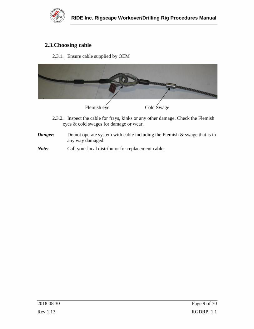
2.3. Choosing cable
2.3.1. Ensure cable supplied by OEM
Flemish eye Cold Swage
2.3.2. Inspect the cable for frays, kinks or any other damage. Check the Flemish
eyes & cold swages for damage or wear.
Danger: Do not operate system with cable including the Flemish & swage that is in
any way damaged.
Note: Call your local distributor for replacement cable.
RIDE Inc. Rigscape Workover/Drilling Rig Procedures Manual
2018 08 30 Page 10 of 70
Rev 1.13 RGDRP_1.1
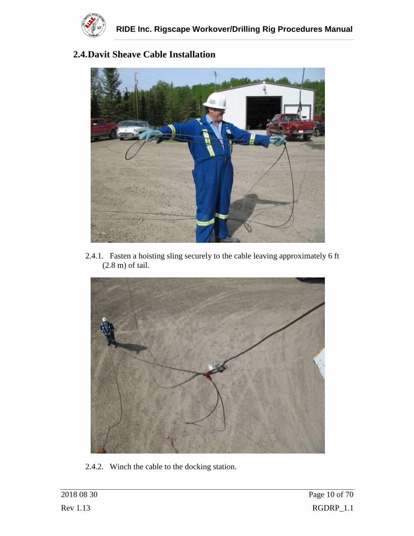
2.4. Davit Sheave Cable Installation
2.4.1. Fasten a hoisting sling securely to the cable leaving approximately 6 ft
(2.8 m) of tail.
2.4.2. Winch the cable to the docking station.

RIDE Inc. Rigscape Workover/Drilling Rig Procedures Manual
2018 08 30 Page 11 of 70
Rev 1.13 RGDRP_1.1
Sheave
2.4.3. Remove rotating sheave cover plate bolt & rotate the cover open.
Warning: Potential bolt dropping, pinch points, overhead hazard for personnel
below, body positioning & fall restraints hazards.
Danger: Do not replace the bolt with any other grade or length bolt.
2.4.4. Check for free rotation of sheave in docking station.
2.4.5. Check for wear or damage to the sheave groove.
2.4.6. Check the davit sheave assembly, bolt, nut & cotter for damage.
2.4.7. Create a 180 return bend on cable and insert it from the open side of the
sheave assembly of the Rigscape docking station.

RIDE Inc. Rigscape Workover/Drilling Rig Procedures Manual
2018 08 30 Page 12 of 70
Rev 1.13 RGDRP_1.1
2.4.8. Draw or pull the cable to the sheave & rotate the sheave assembly cover
closed & replace bolt securely.
2.4.9. Inspect the docking station pivot bolt, nut & cotter pin for damage. Check
that it rotates left to right freely (approx. total rotation 40°).
2.4.10. Disconnect the hoisting sling from the winch line & cable.

RIDE Inc. Rigscape Workover/Drilling Rig Procedures Manual
2018 08 30 Page 13 of 70
Rev 1.13 RGDRP_1.1
2.4.11. Ensure the spring clip is installed correctly on the top side of the docking
station magnetic pocket.

RIDE Inc. Rigscape Workover/Drilling Rig Procedures Manual
2018 08 30 Page 14 of 70
Rev 1.13 RGDRP_1.1
2.5. Magnegress Placement Park-On Anchor
2.5.1 Walk until the cable equalizes. The cable should have a slight tension to the
feel. Mark the end of the cable loop on the ground with the heel of your boot. The
cable can be walked out 20° either side of center. Walk the cable back until the
cable has slackened.
Warning: Releasing the cable while still under tension from the anchor position
could harm personnel and/or damage equipment.
2.5.2 Follow the steps below for the Bear Claw anchor system.
Caution: The Magnegress weighs 160lbs. (75 kg).

RIDE Inc. Rigscape Workover/Drilling Rig Procedures Manual
2018 08 30 Page 15 of 70
Rev 1.13 RGDRP_1.1
2.5.3 Position the back of the Magnegress frame approximately in line to your
mark on the ground.
2.5.4 Remove the protective cover, exposing the Magnegress system.

RIDE Inc. Rigscape Workover/Drilling Rig Procedures Manual
2018 08 30 Page 16 of 70
Rev 1.13 RGDRP_1.1
2.5.5 Remove the long adjustment bolt from the receiver tube on the Magnegress frame
& the short stopper bolt from the tension link.
2.5.6 Install the tension link into the receiver tube from the back side of the
Magnegress. Turn the pinion hand wheel clockwise to draw the tension link into
the receiver tube until the stopper bolt hole is fully exposed on the front side of
the receiver tube.

RIDE Inc. Rigscape Workover/Drilling Rig Procedures Manual
2018 08 30 Page 17 of 70
Rev 1.13 RGDRP_1.1
2.5.7 Insert the stopper bolt, nut & safety pin.
Note: Rack notches face up & towards the pinion hand wheel. Installation of tension link to receiver tube is made easier with two people.
RIDE Inc. Rigscape Workover/Drilling Rig Procedures Manual
2018 08 30 Page 18 of 70
Rev 1.13 RGDRP_1.1
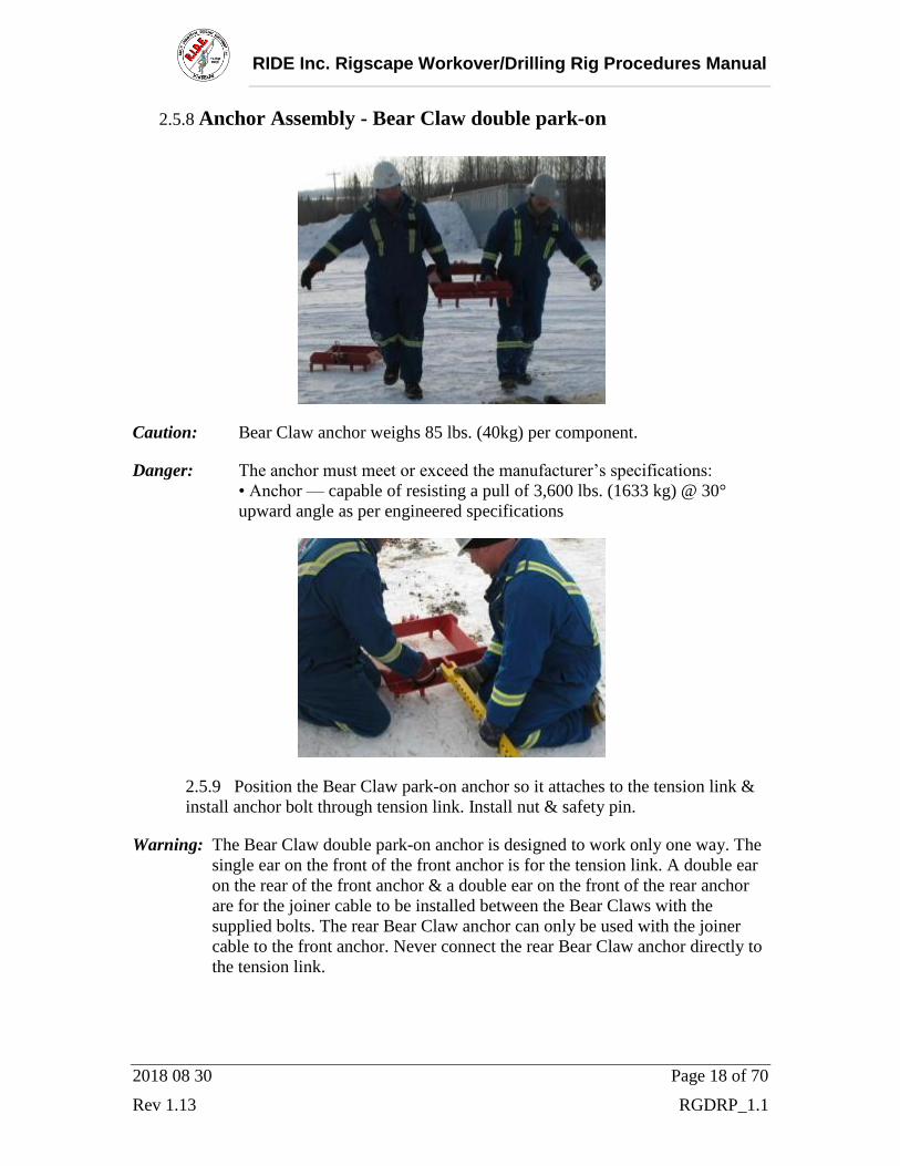
2.5.8 Anchor Assembly - Bear Claw double park-on
Caution: Bear Claw anchor weighs 85 lbs. (40kg) per component.
Danger: The anchor must meet or exceed the manufacturer’s specifications:
• Anchor — capable of resisting a pull of 3,600 lbs. (1633 kg) @ 30°
upward angle as per engineered specifications
2.5.9 Position the Bear Claw park-on anchor so it attaches to the tension link &
install anchor bolt through tension link. Install nut & safety pin.
Warning: The Bear Claw double park-on anchor is designed to work only one way. The
single ear on the front of the front anchor is for the tension link. A double ear
on the rear of the front anchor & a double ear on the front of the rear anchor
are for the joiner cable to be installed between the Bear Claws with the
supplied bolts. The rear Bear Claw anchor can only be used with the joiner
cable to the front anchor. Never connect the rear Bear Claw anchor directly to
the tension link.

RIDE Inc. Rigscape Workover/Drilling Rig Procedures Manual
2018 08 30 Page 19 of 70
Rev 1.13 RGDRP_1.1
2.5.10 Position the secondary Bear Claw park-on anchor so it attaches to the
joiner cable & install joiner cable bolt through two ears capturing the cable
between them. Install nut & safety pin.
2.5.11 Drag the rear Bear Claw anchor back away from the front anchor until the
cable becomes taut.

RIDE Inc. Rigscape Workover/Drilling Rig Procedures Manual
2018 08 30 Page 20 of 70
Rev 1.13 RGDRP_1.1
2.5.12 Align the Magnegress system to the top anchor point.

RIDE Inc. Rigscape Workover/Drilling Rig Procedures Manual
2018 08 30 Page 21 of 70
Rev 1.13 RGDRP_1.1
2.5.13 Secure 2200 lbs (1000kg) onto the Bear Claw double park-on anchor.
Note: If using a truck ensure both front wheels engage onto both of the anchor’s
saddles at the same time.
Note: The truck may have to be rocked forward & back slightly to securely seat the
Bear Claws of the anchor into the soil.
Danger: Ensure all company lock out procedures are performed on the anchoring
vehicle.
2.5.14 Alternatively Drive on with the aid of a block.
2.5.15 If alternate anchor system is used the tension bar must still be secured to
the anchor using supplied bolt.
RIDE Inc. Rigscape Workover/Drilling Rig Procedures Manual
2018 08 30 Page 22 of 70
Rev 1.13 RGDRP_1.1
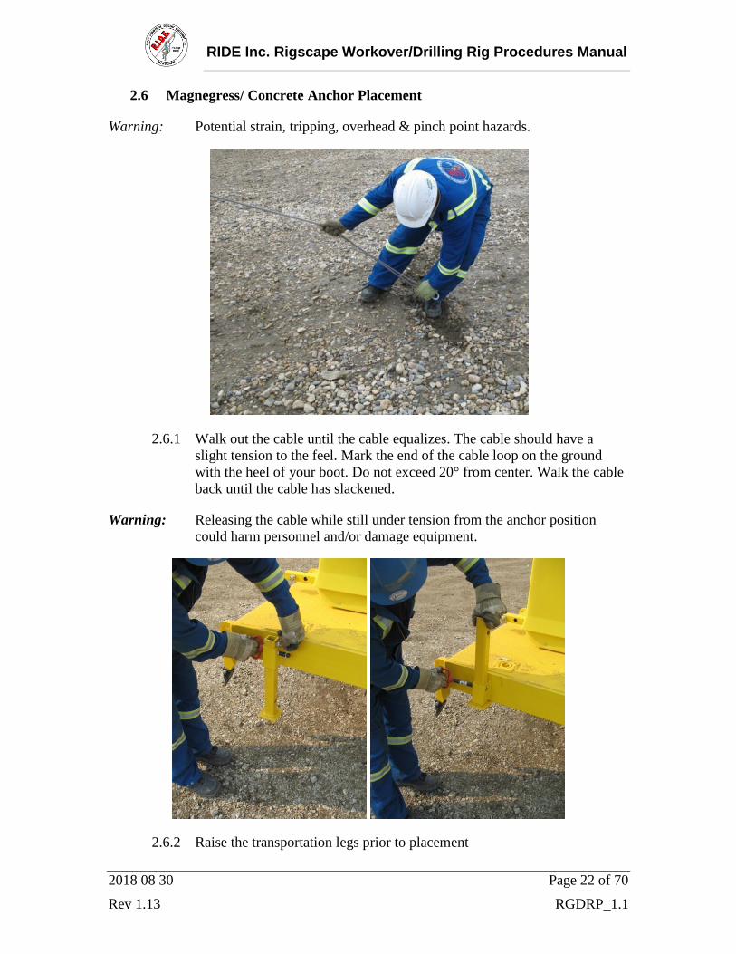
2.6 Magnegress/ Concrete Anchor Placement
Warning: Potential strain, tripping, overhead & pinch point hazards.
2.6.1 Walk out the cable until the cable equalizes. The cable should have a
slight tension to the feel. Mark the end of the cable loop on the ground
with the heel of your boot. Do not exceed 20° from center. Walk the cable
back until the cable has slackened.
Warning: Releasing the cable while still under tension from the anchor position
could harm personnel and/or damage equipment.
2.6.2 Raise the transportation legs prior to placement

RIDE Inc. Rigscape Workover/Drilling Rig Procedures Manual
2018 08 30 Page 23 of 70
Rev 1.13 RGDRP_1.1
2.6.3 Position the front of the anchor approximately in line to your mark on the
ground.
2.6.4 Remove the protective cover, exposing the Magnegress system.

RIDE Inc. Rigscape Workover/Drilling Rig Procedures Manual
2018 08 30 Page 24 of 70
Rev 1.13 RGDRP_1.1
2.7 Magnegress Cable Install
2.7.1 Remove the sheave cover plate from Magnegress brake housing.
Note: Ensure that the cover plate & pins do not become engulfed in foreign debris.
ie: mud, ice, packed snow.
2.7.2 Standing directly under the Rigscape docking station, ensure the cable is
not twisted, by holding each part of the looped cable in each hand &
extending your arms out to your sides spreading the looped cable apart.

RIDE Inc. Rigscape Workover/Drilling Rig Procedures Manual
2018 08 30 Page 25 of 70
Rev 1.13 RGDRP_1.1
2.7.3 Keeping the cable separated grasp cable firmly & walk towards the
Magnegress.
2.7.4 Check the drive sheave debris holes for debris &/or wear.

RIDE Inc. Rigscape Workover/Drilling Rig Procedures Manual
2018 08 30 Page 26 of 70
Rev 1.13 RGDRP_1.1
2.7.5 Cable thread configuration
Flemish Eyes
2.7.6 Create a 180 return bend on cable and insert it around the drive sheave &
in between the idler sheaves of the Magnegress. Ensure the Flemish eyes
are on the upper cable travelling to the top of the top sheave.

RIDE Inc. Rigscape Workover/Drilling Rig Procedures Manual
2018 08 30 Page 27 of 70
Rev 1.13 RGDRP_1.1
2.7.7
2.7.8 Cable must line up with corresponding idler sheave grooves when
installed on the drive sheave.
Danger: Incorrect setup could result in a serious injury.
Warning: Never grab the Flemish eye cable connections directly. The 2 Flemish eye
contact areas are an extreme pinch point area.
Warning: Check the cable for twist.

RIDE Inc. Rigscape Workover/Drilling Rig Procedures Manual
2018 08 30 Page 28 of 70
Rev 1.13 RGDRP_1.1
2.8 Tension Indicator
2.8.1 Rotate out the tension indicator. Side slip the cable across the back stop
pin until the cable slips to the top of the back stop pin.
2.8.2 Turn the pinion hand wheel clock-wise, move the brake assembly away
from rig, there by tightening the cable, tighten until the indicator pad
becomes flush with the top face of the tension indicator. When the two
hole line up, insert the adjustment bolt, install the nut and safety pin.

RIDE Inc. Rigscape Workover/Drilling Rig Procedures Manual
2018 08 30 Page 29 of 70
Rev 1.13 RGDRP_1.1
Warning: Never stick anything except the supplied bolts into the adjustment bolt holes.
Note: It is recommended to go to the next tighter hole in the tension link if the
receiver tube hole is between holes.
2.8.3 Again, side-slip the tensioned cable off of the back stop pin.
2.8.4 Rotate the tension indicator back into the stored position.
2.8.5 Inspect the Magnegress housing cover plate for debris or damage before
reinstalling.

RIDE Inc. Rigscape Workover/Drilling Rig Procedures Manual
2018 08 30 Page 30 of 70
Rev 1.13 RGDRP_1.1
2.9 Magnegress Override-Brake Setup
2.9.1 After the cable is installed onto the Magnegress begin the Magnegress
Override-brake procedures.
2.9.2 With the cover off check that the brake pad moves freely & that the spring
returns the pad to its resting position against the back plate of the cover
(arrow).
2.9.3 Place the cover onto the Magnegress brake system.

RIDE Inc. Rigscape Workover/Drilling Rig Procedures Manual
2018 08 30 Page 31 of 70
Rev 1.13 RGDRP_1.1
2.9.4 Insert all three cover safety pins.
2.9.5 The following steps are only required when the override-brake is required.
2.9.6 Check to see that the spring pin is properly inserted into the override-brake
handle.

RIDE Inc. Rigscape Workover/Drilling Rig Procedures Manual
2018 08 30 Page 32 of 70
Rev 1.13 RGDRP_1.1
2.9.7 Insert handle into the override-brake hub.
2.9.8 Insert safety pin into the back side of the handle.

RIDE Inc. Rigscape Workover/Drilling Rig Procedures Manual
2018 08 30 Page 33 of 70
Rev 1.13 RGDRP_1.1
2.9.9 This is a view of the assembled override-brake with handle installed.
2.9.10 Apply pressure on the handle as in the direction indicated on the
Magnegress cover.

RIDE Inc. Rigscape Workover/Drilling Rig Procedures Manual
2018 08 30 Page 34 of 70
Rev 1.13 RGDRP_1.1
2.9.11 The override brake pad (arrow) should ride the center of the outer sheave.
Note: Cover plate will not fit on the Magnegress housing if something is not
properly in place. If this happens check cable orientation on sheave,
tension indicator orientation or debris.
Danger: All 3 cover plate pins must be installed during operation.
2.9.12 Re-install the Magnegress protective cover.

RIDE Inc. Rigscape Workover/Drilling Rig Procedures Manual
2018 08 30 Page 35 of 70
Rev 1.13 RGDRP_1.1
2.10 Trolley
2.10.1 Pull & turn the lock-pin knob to lift the locking pin out of the locking pin
opening.
2.10.2 Rotate the sheave gate knob on the trolley counter clockwise until the
knob becomes completely disconnected from the threaded shaft.
2.10.3 Check that the secondary brake operates freely, the brake pad is not
excessively worn & that the sheave rotates freely.

RIDE Inc. Rigscape Workover/Drilling Rig Procedures Manual
2018 08 30 Page 36 of 70
Rev 1.13 RGDRP_1.1
2.10.4 Place the cold swage, located on the upside or monkey board side of the
Flemish eye, inside the trolley, above the sheave. Insert the lower cable
inside the trolley as well but underneath the sheave. (arrow points towards
Magnegress)
Caution: Ensure Flemish eye swage is not getting pinched in between the gate & body
while tightening the sheave gate knob.
Danger: The cold cable swage must become trapped inside the trolley on the top side
of the sheave.
2.10.5 Close the sheave gate & tighten the sheave gate knob clockwise until
snug. Turn the lock-pin knob until it drops into the lock position (DO
NOT use wrenches to tighten). Inspect the sheave gate’s locator flap for
damage & for proper fit.
Note: The sheave gate knob may have to be rotated counter-clockwise slightly to allow
for the lock pin to engage.

RIDE Inc. Rigscape Workover/Drilling Rig Procedures Manual
2018 08 30 Page 37 of 70
Rev 1.13 RGDRP_1.1
2.11. Rigscape shuttle
2.11.1 Insert the shuttle connector tube into the trolley receiver tube & install the
keeper bolt, nut & safety pin.
2.11.2 Lower the seat into the working position.

RIDE Inc. Rigscape Workover/Drilling Rig Procedures Manual
2018 08 30 Page 38 of 70
Rev 1.13 RGDRP_1.1
2.12.1 Old Fall Arrest & Spacer Bar Connection
2.12.1.1 Install the pivoting fall arrest trolley by rotating the around both
cables.
Warning: If both cables are not enclosed within the fall arrest trolley it will impede
the operation of the system & injury could occur.
2.12.1.2 Insert the shuttle receiving pin into the receiving tube of the fall
arrest trolley spacer.

RIDE Inc. Rigscape Workover/Drilling Rig Procedures Manual
2018 08 30 Page 39 of 70
Rev 1.13 RGDRP_1.1
2.12.1.3 Install the pin through this assembly.

RIDE Inc. Rigscape Workover/Drilling Rig Procedures Manual
2018 08 30 Page 40 of 70
Rev 1.13 RGDRP_1.1
2.12.2 New Fall Arrest & Spacer Bar Connection
2.12.2.1 Insert the Fall Arrest Trolley pin into the Spacer bar & pin the
assembly.
2.12.2.2 Intersect the two ends through the open slots.

RIDE Inc. Rigscape Workover/Drilling Rig Procedures Manual
2018 08 30 Page 41 of 70
Rev 1.13 RGDRP_1.1
2.12.2.3 Pivot & rotate the Trolley & Spacer Bar assembly.
2.12.2.4 Install the pivoting fall arrest trolley by rotating the arm around both
cables.
Warning: If both cables are not enclosed within the fall arrest trolley it will impede
the operation of the system & injury could occur.

RIDE Inc. Rigscape Workover/Drilling Rig Procedures Manual
2018 08 30 Page 42 of 70
Rev 1.13 RGDRP_1.1
2.12.2.5 Attach the SRL (Self-Retracting Lanyard) into the SRL anchor hole
of the mount.
Note: Recommended SRL 10’ (3 m) MSA cable workman.
2.12.2.6 Inspect SRL device as per the manufacturer’s specification.
2.12.2.7 Hoisting up to the docking station can be done in 3 different ways.
2.12.2.8 Connect a platform mounted winch cable to the winch eye on the
shuttle & winch it up to the docking station, slowing at the top and guiding the
trolley into the docking station by hand. Disconnect the winch cable after
docking is complete.
Warning: Clear communication must be established between the person on the
winch & the person docking the trolley to ensure not to over pull on the
winch causing damage to the system.

RIDE Inc. Rigscape Workover/Drilling Rig Procedures Manual
2018 08 30 Page 43 of 70
Rev 1.13 RGDRP_1.1
2.12.3 Extended Davit Fall Arrest Connection
(Option)
2.12.3.1 Intersect the two ends through the open slots.
2.12.3.2 Pivot & rotate the Trolley & Spacer Bar assembly.
RIDE Inc. Rigscape Workover/Drilling Rig Procedures Manual
2018 08 30 Page 44 of 70
Rev 1.13 RGDRP_1.1
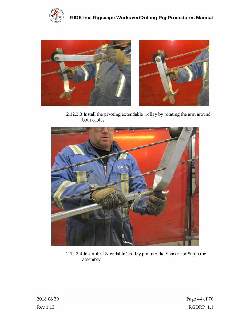
2.12.3.3 Install the pivoting extendable trolley by rotating the arm around
both cables.
2.12.3.4 Insert the Extendable Trolley pin into the Spacer bar & pin the
assembly.

RIDE Inc. Rigscape Workover/Drilling Rig Procedures Manual
2018 08 30 Page 45 of 70
Rev 1.13 RGDRP_1.1
2.12.3.5 Intersect the two ends through the open slots. Then pivot & rotate
the Pivoting Extendable Fall Arrest Trolley & Secondary Spacer
Bar assembly.
2.12.3.6 Install the pivoting fall arrest trolley by rotating the arm around
both cables.

RIDE Inc. Rigscape Workover/Drilling Rig Procedures Manual
2018 08 30 Page 46 of 70
Rev 1.13 RGDRP_1.1
2.12.3.7 Insert the Fall Arrest Trolley pin into the Spacer bar & pin the
assembly.
2.12.3.8 Attach the SRL (Self-Retracting Lanyard) into the SRL anchor
hole of the mount.
Note: Recommended SRL 10’ (3 m) MSA cable workman.

RIDE Inc. Rigscape Workover/Drilling Rig Procedures Manual
2018 08 30 Page 47 of 70
Rev 1.13 RGDRP_1.1
2.12.3.9 Inspect SRL device as per manufacturer’s specification

RIDE Inc. Rigscape Workover/Drilling Rig Procedures Manual
2018 08 30 Page 48 of 70
Rev 1.13 RGDRP_1.1
2.13. Raising And Docking Shuttle
2.13.1 Hoisting up to the docking station can be done in 3 different ways.
2.13.2 Connect a platform mounted winch cable to the winch eye on the
shuttle & winch it up to the docking station, slowing at the top and
guiding the trolley into the docking station by hand. Disconnect the
winch cable after docking is complete.
Warning: Clear communication must be established between the person on the
winch & the person docking the trolley to ensure not to over pull on the
winch causing damage to the system.
2.13.3 Pulling the lower cable towards the Magnegress & pulling the
upper cable towards the docking station will propel the trolley &
shuttle assembly up to the person at the docking station waiting to
guide it into place.

RIDE Inc. Rigscape Workover/Drilling Rig Procedures Manual
2018 08 30 Page 49 of 70
Rev 1.13 RGDRP_1.1
2.13.4 Inspect the optional electric shuttle lift tool & its components.
2.13.5 Ensure the Magnegress sheave cover is on, set the switch on the
shuttle lift tool to the forward position (photo), place the socket on
the nut of the Magnegress sheave & engage trigger to raise the
shuttle.
Note: Once the shuttle reaches the docking station the cable will slip in the
sheave.
2.13.6 When finished with the shuttle lifting tool return it back into its
carrying case & back into the anchor toolbox to avoid damage.

RIDE Inc. Rigscape Workover/Drilling Rig Procedures Manual
2018 08 30 Page 50 of 70
Rev 1.13 RGDRP_1.1
2.13.7 Guide the shuttle into the receiving tracks on the archway.
2.13.8 Guide the two docking pins into the docking station’s magnetic
receiver tubes.

RIDE Inc. Rigscape Workover/Drilling Rig Procedures Manual
2018 08 30 Page 51 of 70
Rev 1.13 RGDRP_1.1
2.13.9 Insert safety cable pin from the one side of the shuttle into the
receiver mount on the other side of the shuttle.
Danger: The pin must fit within the notch in the track on the archway.
2.13.10 Upon entering onto the working platform, the SRL must be
connected to a certified harness to the rear shoulder-height D-Ring
before disconnecting from the rig mounted fall arrest.
2.13.11 It is very imperative that you connect before you disconnect.
Connect to the fall-arrest on the Rigscape shuttle’s SRL mount.
Once you confirm the connection is secure you may disconnect from
the rig mounted fall-arrest.
Danger: You must not be tied off to anything other than the Rigscape system at this
point.

RIDE Inc. Rigscape Workover/Drilling Rig Procedures Manual
2018 08 30 Page 52 of 70
Rev 1.13 RGDRP_1.1
2.13.12 Connect the shuttle mounted work positioning lanyard to your
harness waste belt D-ring.
2.13.13 Establish and clear restricted work area.
Danger: Ensure all personnel and operators of vehicles or equipment are aware of
the cable, block anchor or anchoring vehicle and restricted area.
Note: Nylon ribbon may be attached to the cable as a visual aid.

RIDE Inc. Rigscape Workover/Drilling Rig Procedures Manual
2018 08 30 Page 53 of 70
Rev 1.13 RGDRP_1.1
2. Operation
3.1 Safety notes reminder
3.1.1 Read these warnings carefully before inspecting, setting
up, installing, using, or tearing down the Rigscape system.
3.1.2 Wear mandatory personal protection equipment at
all times.
3.1.3 Use proper lifting techniques when inspecting,
setting up, installing, or tearing down the Rigscape
system. Refer to Specifications (i.) for product
weights.
3.1.4 Watch for pinch points when inspecting, setting up,
installing, using, or tearing down the Rigscape
system.
3.1.5 Watch for tripping hazards when inspecting, setting
up, installing, using, or tearing down the Rigscape
system.
3.1.6 Do not use the Rigscape system unless you are
wearing a safety harness and are secured only to the
Rigscape fall-arrest device and working lanyard.
3.1.7 This Rigscape is designed for single person only.
3.1.8 Never drive over your cables
3.1.9 Double check the system every day if set up for
extended periods between moves.
3.1.10 Ensure all personnel and operators of vehicles or
equipment are aware of the cable, anchor, anchor
vehicle and restricted area.
3.1.11 An investigation must follow any and all incidents
to determine the cause and the corrective actions to
be taken. Notify the manufacturer, RIDE Inc. at
780-621-1570.

RIDE Inc. Rigscape Workover/Drilling Rig Procedures Manual
2018 08 30 Page 54 of 70
Rev 1.13 RGDRP_1.1
3.2. General Operations
3.2.1 It is very important that you connect before you disconnect.
Connect to the SRL on the Rigscape shuttle. Once you confirm
the connection is secure you may disconnect from the rig
mounted fall-arrest.
Danger: You must not be tied off to anything other than the Rigscape shuttle at this
point.
3.2.2 Connect the shuttle mounted work positioning lanyard to your
harness waste belt D-ring.

RIDE Inc. Rigscape Workover/Drilling Rig Procedures Manual
2018 08 30 Page 55 of 70
Rev 1.13 RGDRP_1.1
3.2.3 If the alarm sounds or an emergency occurs, in one motion as you
walk off the working platform the safety cable will contact the
lower part of your thigh & release the shuttle’s secondary
securement. Step out & sit down onto the shuttle seat. The weight
activated release mechanism will then disengage the shuttle.
Caution: Ensure that the work position lanyard is controlled upon exit. This means:
3.2.4 Grab the work positioning lanyard approximately in the middle
with your hand ensuring that the work positioning lanyard will not
snag on any obstructions at the point of egress.
3.2.5 The Magnegress brake will automatically control your descent.

RIDE Inc. Rigscape Workover/Drilling Rig Procedures Manual
2018 08 30 Page 56 of 70
Rev 1.13 RGDRP_1.1
3.2.6 The Rigscape system is equipped with a redundant brake & is
simply operated by pulling down on handle (arrow).
3.2.7 Record every run of the Rigscape system in the Log Book.

RIDE Inc. Rigscape Workover/Drilling Rig Procedures Manual
2018 08 30 Page 57 of 70
Rev 1.13 RGDRP_1.1
4 Teardown
Option A: 4.1 This procedure assumes the Rigscape shuttle is still attached to the rig
platform. Ride the Rigscape shuttle down to the ground. If the Rigscape
shuttle has been run down to the ground, then continue with Step 4.3 of
this procedure.
Option B: 4.2 Undock shuttle from docking station & leave suspended on line.
4.3 From ground position pull shuttle down with cable using the hand
over hand technique.
4.4 Detach the SRL (Self-Retracting Lanyard) & shuttle mounted lanyard
from the shuttle.
4.4.1
4.5 Remove Fall Arrest Trolley and Spacer Bar from Shuttle
4.5.1
4.5.2

RIDE Inc. Rigscape Workover/Drilling Rig Procedures Manual
2018 08 30 Page 58 of 70
Rev 1.13 RGDRP_1.1
4.6 Disconnect the shuttle from the trolley by removing the
keeper bolt, nut & safety pin. Replace bolt, nut & pin into
the disassembled system. Unpin and raise seat into
transport position
4.6.1
4.6.2
4.7 Pull the lock-pin knob then turn to the unlocked position & loosen the
trolley sheave gate knob until the gate is opened. Picture 4.3.1
4.7.1
Caution: Watch for pinch points when removing trolley from cable.

RIDE Inc. Rigscape Workover/Drilling Rig Procedures Manual
2018 08 30 Page 59 of 70
Rev 1.13 RGDRP_1.1
4.8 Remove the upper & lower cable from inside the trolley housing.
4.8.1
4.9 Remove the Magnegress housing cover plate & the 3 cover plate
keeper pins.
4.9.1
4.10 Turn the pinion hand wheel clock-wise to remove tension on the
adjustment bolt at this point, a second person should be used to
remove the adjustment bolt. Then turn the pinion wheel counter
clock-wise all the way to the stopper bolt to loosening the cable.
4.10.1
Caution: Watch for pinch points when removing the cable.

RIDE Inc. Rigscape Workover/Drilling Rig Procedures Manual
2018 08 30 Page 60 of 70
Rev 1.13 RGDRP_1.1
4.11 Remove the cable from the Magnegress brake housing.
4.11.1
Warning: Releasing the cable while still under tension from the docking station
could slide fast & hit personnel and/or equipment.
4.12 Install the Magnegress housing cover plate & re-install the 3 cover
plate keeper pins.
4.13 Reinstall the Magnegress cage cover.
4.14 Strap & secure the Magnegress to the anchor.
4.15 Strap & secure the shuttle assembly to the anchor.
4.15.1
RIDE Inc. Rigscape Workover/Drilling Rig Procedures Manual
2018 08 30 Page 61 of 70
Rev 1.13 RGDRP_1.1
5 Maintenance
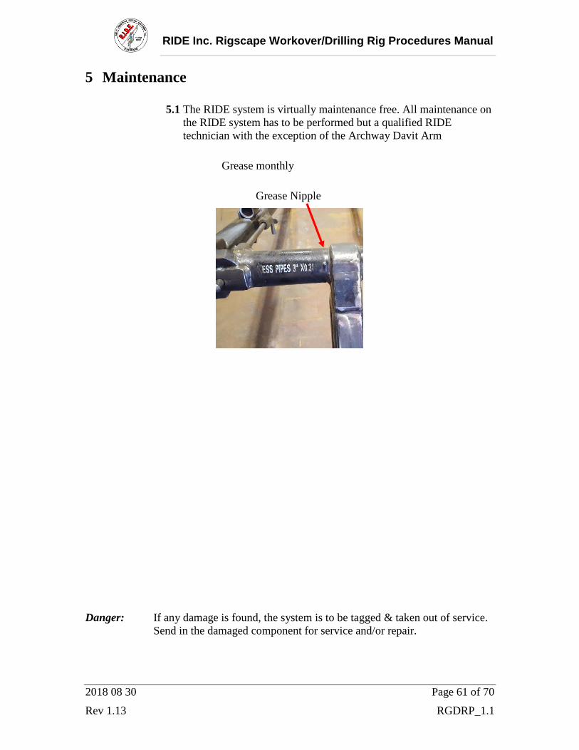
5.1 The RIDE system is virtually maintenance free. All maintenance on
the RIDE system has to be performed but a qualified RIDE
technician with the exception of the Archway Davit Arm
Grease monthly
Grease Nipple
Danger: If any damage is found, the system is to be tagged & taken out of service.
Send in the damaged component for service and/or repair.

RIDE Inc. Rigscape Workover/Drilling Rig Procedures Manual
2018 08 30 Page 62 of 70
Rev 1.13 RGDRP_1.1
6 Descent Log
6.1 Every time the Rigscape system is used, its use must be recorded in
a Log Book.
6.2 The Log must accompany the Rigscape system when it goes for its
annual inspection / certification.
6.3 Sample decent log on following page.

RIDE Inc. Rigscape Workover/Drilling Rig Procedures Manual
2018 08 30 Page 63 of 70
Rev 1.13 RGDRP_1.1
Trg
Em
g
RO
Sig
nat
ure
Ap
pli
cati
on
Co
de:
:Tra
inin
g .
:Em
erg
ency
.
:Rig
ou
t .
po
siti
on
N
ame
(pri
nt)
p
osi
tio
n
Sig
nat
ure
N
ame
(pri
nt)
6.4
Insp
ecti
on
an
d M
ain
ten
ance
Rem
ind
ers:
4.
Insp
ect
cab
le f
or
wea
r o
r d
amag
e.
2.
Str
uct
ura
l In
spec
tio
n e
ver
y 3
yea
rs.
(by
a q
ual
ifie
d p
erso
n a
uth
ori
zed
by
Man
ufa
ctu
re &
do
cum
ente
d)
3.
Insp
ect
shea
ves
fo
r w
ear
as i
nd
icat
ed o
n t
he
sid
e p
late
an
d/o
r in
th
e m
anu
al
1.
1 y
ear
fro
m i
n s
erv
ice
dat
e a
vis
ual
in
spec
tio
n r
equ
ire
by
a q
ual
ifie
d p
erso
n a
uth
ori
zed
by
Man
ufa
ctu
re &
do
cum
ente
d
En
sure
th
e lo
gs
are
up
to
dat
e an
d a
cco
mp
any
th
e sy
stem
wh
en s
ent
in f
or
the
3 y
ear
insp
ecti
on
.
R.I
.D.E
. In
c.
Des
cen
t L
og
Rig
#_
__
__
__
__
__
__
Ap
pli
cati
on
use
Ph
on
e #
__
__
__
__
__
__
__
__
__
__
__
__
__
__
__
__
__
__
Au
tho
rize
d b
y
Co
mp
any
__
__
__
__
__
__
__
_
Mag
neg
ress
Ser
ial
# _
__
__
__
__
__
__
__
_
Rid
er
Co
mp
any
Co
nta
ct_
__
__
__
__
__
__
__
__
__
__
__
__
__
Rig
scap
e S
eria
l #
__
__
__
__
__
__
Dat
e

RIDE Inc. Rigscape Workover/Drilling Rig Procedures Manual
2018 08 30 Page 64 of 70
Rev 1.13 RGDRP_1.1
Trg
Em
g
RO
Sig
nat
ure
Ap
pli
cati
on
Co
de:
:Tra
inin
g .
:Em
erg
ency
.
:Rig
ou
t .
po
siti
on
N
ame
(pri
nt)
p
osi
tio
n
Sig
nat
ure
N
ame
(pri
nt)
6.4
4.
Insp
ect
cab
le f
or
wea
r o
r d
amag
e.
1.
1 y
ear
fro
m i
n s
erv
ice
dat
e a
vis
ual
in
spec
tio
n r
equ
ire
by
a q
ual
ifie
d p
erso
n a
uth
ori
zed
by
Man
ufa
ctu
re &
do
cum
ente
d
2.
Str
uct
ura
l In
spec
tio
n e
ver
y 3
yea
rs.
(by
a q
ual
ifie
d p
erso
n a
uth
ori
zed
by
Man
ufa
ctu
re &
do
cum
ente
d)
3.
Insp
ect
shea
ves
fo
r w
ear
as i
nd
icat
ed o
n t
he
sid
e p
late
an
d/o
r in
th
e m
anu
al
Insp
ecti
on
an
d M
ain
ten
ance
Rem
ind
ers:
En
sure
th
e lo
gs
are
up
to
dat
e an
d a
cco
mp
any
th
e sy
stem
wh
en s
ent
in f
or
the
3 y
ear
insp
ecti
on
.
R.I
.D.E
. In
c.
Des
cen
t L
og
Rig
#_
__
__
__
__
__
__ Ap
pli
cati
on
use
Ph
on
e #
__
__
__
__
__
__
__
__
__
__
__
__
__
__
__
__
__
__
Au
tho
rize
d b
y
Co
mp
any
__
__
__
__
__
__
__
_
Mag
neg
ress
Ser
ial
# _
__
__
__
__
__
__
__
_
Rid
er
Co
mp
any
Co
nta
ct_
__
__
__
__
__
__
__
__
__
__
__
__
__
Rig
scap
e S
eria
l #
__
__
__
__
__
__
Dat
e

RIDE Inc. Rigscape Workover/Drilling Rig Procedures Manual
2018 08 30 Page 65 of 70
Rev 1.13 RGDRP_1.1
Trg
Em
g
RO
Sig
nat
ure
Ap
pli
cati
on
Co
de:
:Tra
inin
g .
:Em
erg
ency
.
:Rig
ou
t .
po
siti
on
N
ame
(pri
nt)
p
osi
tio
n
Sig
nat
ure
N
ame
(pri
nt)
6.4
2.
Str
uct
ura
l In
spec
tio
n e
ver
y 3
yea
rs.
(by
a q
ual
ifie
d p
erso
n a
uth
ori
zed
by
Man
ufa
ctu
re &
do
cum
ente
d)
3.
Insp
ect
shea
ves
fo
r w
ear
as i
nd
icat
ed o
n t
he
sid
e p
late
an
d/o
r in
th
e m
anu
al
Insp
ecti
on
an
d M
ain
ten
ance
Rem
ind
ers:
4.
Insp
ect
cab
le f
or
wea
r o
r d
amag
e.
En
sure
th
e lo
gs
are
up
to
dat
e an
d a
cco
mp
any
th
e sy
stem
wh
en s
ent
in f
or
the
3 y
ear
insp
ecti
on
.
R.I
.D.E
. In
c.
Des
cen
t L
og
Rig
#_
__
__
__
__
__
__
Ap
pli
cati
on
use
Ph
on
e #
__
__
__
__
__
__
__
__
__
__
__
__
__
__
__
__
__
__
Au
tho
rize
d b
y
Co
mp
any
__
__
__
__
__
__
__
_
Mag
neg
ress
Ser
ial
# _
__
__
__
__
__
__
__
_
Rid
er
Co
mp
any
Co
nta
ct_
__
__
__
__
__
__
__
__
__
__
__
__
__
Rig
scap
e S
eria
l #
__
__
__
__
__
__
Dat
e
1.
1 y
ear
fro
m i
n s
erv
ice
dat
e a
vis
ual
in
spec
tio
n r
equ
ire
by
a q
ual
ifie
d p
erso
n a
uth
ori
zed
by
Man
ufa
ctu
re &
do
cum
ente
d

RIDE Inc. Rigscape Workover/Drilling Rig Procedures Manual
2018 08 30 Page 66 of 70
Rev 1.13 RGDRP_1.1
7 Appendix
Rig Specific Information
A) Company: __________
B) Rig #: __________________ C) Contact Person: _____________
D) Contact Phone: _____________
E) Rig Type: single double triple
F) Style: telescopic solid mast
G) Monkey Board sheave Height: ____________
H) Ground Anchor to Well Head Center: ___________________________________
I) Ground Anchor Point to Back of Monkey Board: ___________________________
J) Ground Anchor to front of sub structure: _________________________________
K) Cable Length: ______________________________
L) Rigscape Serial #: ____________________________

RIDE Inc. Rigscape Workover/Drilling Rig Procedures Manual
2018 08 30 Page 67 of 70
Rev 1.13 RGDRP_1.1
7.1 Orientation Sign-off
7.1.1 Print, sign your name and date at the bottom of the
page in the space provided, indicating that you have
read and understand the information in each section
of the Ride Inc. Rigscape Service Rig Procedure
Manual.
Section
2. Set up
2.2. Docking station
2.3. Magnegress
2.4. Anchorage
2.5. Magnegress sheave
2.6. Magnegress tension
2.7. Trolley
2.8. Rigscape shuttle
3.2. Operations
4. Tear down
Print Name Signature Date
_______________________ __________________________ __________
_______________________ __________________________ __________
_______________________ __________________________ __________
_______________________ __________________________ __________
_______________________ __________________________ __________
_______________________ __________________________ __________
_______________________ __________________________ __________
_______________________ __________________________ __________
_______________________ __________________________ __________
_______________________ __________________________ __________

RIDE Inc. Rigscape Workover/Drilling Rig Procedures Manual
2018 08 30 Page 68 of 70
Rev 1.13 RGDRP_1.1
2017
Archway Gate
2017/11/21
Rev 1.0
RIDE Inc. Archway Gate Operation Procedures
Special Instructions/Conditions of Use
Reading user procedure manual prior to use is essential
Only persons that have been deemed competent in the
operation of the system should operate the system

RIDE Inc. Rigscape Workover/Drilling Rig Procedures Manual
2018 08 30 Page 69 of 70
Rev 1.13 RGDRP_1.1
RIDE Archway Gate Operation
Under normal operations when the Ride shuttle is not in its docked position the gate is
closed
This provide a safety barrier in the archway opening for the worker
Gate remains closed while the worker docks the RIDE shuttle

RIDE Inc. Rigscape Workover/Drilling Rig Procedures Manual
2018 08 30 Page 70 of 70
Rev 1.13 RGDRP_1.1
Once shuttle docked and secondary cable is in place the gate is opened
Gate Operation
Gate Closed To Open: Step#1 Step#2 Step#3
Raise Bar Pull bar outward Lower bar
Raise Bar
Gate remains open at all times while shuttle docked.