word template portrat
TRANSCRIPT
1
Vodafone Business
Surveillance User Guide
IP470 Installation

Vodafone Business Surveillance – IP470 Installation User Guide
C1 – Public Page 2
Contents 1. Introduction 4
2. Basic operations of the unit 6
Device connectors 6
Powering the device and switching it on/off 7
Default LAN port IP Addresses 7
Connecting IP cameras 7
Storage medium 7
Updating the software on the unit 7
3. Configuring communications on the HD-IP470 8
Connecting over a 3G/4G cellular network 8
Connecting over a wired LAN connection 9
4. Accessing the local web setup interface 11
Connecting to the encoder’s local web setup interface 11
5. Overview of the key setup steps 13
Step 1 – Configure the communications settings 13
Step 2 - Enter the encoder’s Vodafone Business Surveillance settings 15
Step 3 - Adding video feeds to the encoder 16
Step 4 – Setting recording settings 19
6. User Accounts 21
Managing Server-wide Administrators 26
Managing domain users 26
User details page 27
Introducing Role-based access control 21
7. Additional configuration options 29
Change time zone 29
NTP Service 29
SecureConnect 29

Vodafone Business Surveillance – IP470 Installation User Guide
C1 – Public Page 3
8. Appendix A - Troubleshooting and frequently asked questions 30
How many channels does the HD-IP470 support? 30
What level of recording and streaming performance is achievable? 30
What recording functions does the HD-IP470 support? 30
What indicative recording times and streaming rates are achievable? 30
What bearers can the HD-IP470 use to transmit video to EdgeVis Server? 31
How does EdgeVis Server licensing work in relation to the HD-IP470? 31
What web browser can I use for the setup? 31
What if I need to restore the encoder to default factory settings? 31
What if the encoder can’t connect to my Vodafone Business Surveillance Server? 31
9. Appendix B - Troubleshooting camera discovery issues 32
What makes and models of IP camera does the encoder support? 32
What if I cannot see my camera listed when I search for cameras? 32
What if I cannot successfully add the IP camera? 32
What if I don’t know the IP address (or login details) of my IP camera? 33
Setting the IP address on a camera to function with an encoder 33
Setting the IP address of a port to function with an existing camera 33
What if my IP camera supports multiple video streams? 33
Camera Compatibility Guide 33
10. Appendix C – Vehicle Installation 35
Dimensions and fixings for in-vehicle installation 35
Connecting the HD-IP470 to a vehicle battery 35
11. Appendix D – Technical Specification and connectors 36
CE COMPLIANCE STATEMENT 37
12. Next steps… 38
Installing a viewing client 38
Configuring the streaming parameters 38

Vodafone Business Surveillance – IP470 Installation User Guide
C1 – Public Page 4
1. Introduction
This document will help set up and configure HD-IP470, allowing it to record and be viewable remotely from a Vodafone Business Surveillance Server.
Before proceeding with the installation and setup of your HD-IP470 unit, please ensure that you check the
package contents listed below, refer to the installation notes on the next page and consult the Quick Start
Guide that was supplied with your unit for step-by-step instructions on preparing hardware and software
components.
To operate this device, you will need to set up, or have access to, the following architecture:
To proceed you must have access to the Vodafone Business Surveillance Server, with an account created for
the encoder to use.
1.10 What is in the box? EdgeVis encoder EdgeVis HD-IP470
Accessories AC/DC 12V power supply, mains power lead, DC power block, two cellular
antennae, two Wi-Fi antennae, mounting plate
Printed materials Quick Start Guide
1.11 Safety Notes The HD-IP470 can operate in temperatures from -20˚C to +50˚C (+55˚C without POE) whilst powered
from 12V – 35V DC.
All deployments of an HD-IP470 encoder unit should ensure that the device is not
mounted:
Within explosive zones
Within 0.5m of a powered transmitter and/or receiver antenna
Within the engine bay/compartment of a vehicle
Within 1m of a vehicle fuel fill point (direct line of sight)
Vodafone Business
Surveillance Encoders
Vodafone Business
Surveillance Clients
Vodafone Business
Surveillance Server
send video to sends video to
SS
D

Vodafone Business Surveillance – IP470 Installation User Guide
C1 – Public Page 5
WARNING: The HD-IP470 Encoder has been designed to operate from an 12V – 35V DC supply. Do
not connect it directly to mains power outlet. Use the AC/DC adapter supplied with the unit.
The following precautions must be taken to avoid damage to the unit:
DO NOT CONNECT DIRECTLY TO THE MAINS SUPPLY
Always ensure the supply is within the specified voltage range and employ suitable
filtering if voltage spikes are likely
Do not reverse the polarity of the DC power supply. It will cause irreparable
damage to the HD-IP470
Always provide a common ground between the HD-IP470 unit and all connected
equipment
WARNING: Do not exceed power supply input voltage.
Do not connect to a power supply over 35V – this will damage the unit.
WARNING: Failure to observe these precautions will invalidate the warranty.

Vodafone Business Surveillance – IP470 Installation User Guide
C1 – Public Page 6
2. Basic operations of the unit
The EdgeVis HD-IP470 is a small and robust device, ideally suited for use in fixed installations for the recording and live streaming of video from a multiple IP cameras.
Device connectors The HD-IP470 features integral TVI streaming using an internal 4G modem, internal Wi-Fi adapter or wired
LAN, and archiving onto internal drive. The device supports the connection of multiple IP cameras.
Connectors for the HD-IP470 are shown below.
s
Panel Layout
1 Power input connector. 6 GPS antenna connector.
2 PoE+ ethernet ports 7 Serial ports.
3 USB 3.0 ports. 8 Cellular antenna connectors.
4 Ethernet port. 9 Wi-Fi antenna connectors.
5 USB 2.0 ports. 10 Digital I/O triggers port.
Note: DVI/VGA, CAN, audio connectors and power button are not used.
1 2 3
4
5
6
7
8 9
10

Vodafone Business Surveillance – IP470 Installation User Guide
C1 – Public Page 7
Powering the device and switching it on/off To switch the unit on simply connect the output cable from the AC/DC adapter to the DC input connector
on the front panel of the HD-IP470 and connect the AC/DC adapter to the mains power outlet. Alternatively,
wire up an appropriate DC input cable to the encoder that supplies 9-35V DC.
Default LAN port IP Addresses For ease of deployment each LAN port on the HD-IP470 device is pre-configured with a static IP address:
Connecting IP cameras The HD-IP470 allows for connection of multiple IP cameras via the ethernet ports located on the front of
the unit. The cameras should be connected to the device using standard Ethernet cable.
Supported cameras are detailed in the camera compatibility section.
Storage medium The HD-IP470 can record video to the internal drive or an external USB storage device. Further details on
how to properly prepare a recording disk refer to later in the user guide.
Updating the software on the unit There are two ways to update the firmware – locally using a USB Pen, or remotely using Vodafone Business
Surveillance Server.
To update remotely, upload the new firmware to the Firmware page within the Vodafone Business
Surveillance Server web interface and then, from the Encoder’s status and diagnostics page, select
Upgrade Firmware from the menu on the right-hand side.
To update locally, copy the update onto a USB flash drive and insert into a USB port on the front of
the unit. The flash drive can be inserted into a running unit or before the unit is powered up. The
update procedure will cause the LEDs under the Ethernet and USB ports to cycle. When the update
is complete, all LEDs will remain on. At this point it is safe to remove the pen and the unit will
automatically reboot.
LAN Port Default IP Address Subnet mask
LAN 192.168.10.1 255.255.255.0
PoE+ 1 192.168.11.1 255.255.255.0
PoE+ 2 192.168.12.1 255.255.255.0
USB Ethernet
(not supplied)
192.168.20.1 255.255.255.0

Vodafone Business Surveillance – IP470 Installation User Guide
C1 – Public Page 8
3. Configuring communications on the HD-
IP470
The HD-IP470 supports communications over wired LAN and Cellular.
Connecting over a 3G/4G cellular network A valid mobile SIM card is required in order to connect the HD-IP470 over a cellular communications
bearer. The unit has an inbuilt modem for 3G/4G connection with 3G/4G antenna connectors on the side
of the device. Note: despite the ultra-efficient bandwidth usage achieved by TVI, the HD-IP470 is
considered a heavy data use product on cellular networks. It is recommended that an unlimited data plan
(or if unavailable, a heavy consumption data plan) is set up with your Mobile Network Service Provider for
use with the HD-IP470.
The SIM card holder is located inside the unit under the modem card – this supports a standard size SIM
card. To install micro or nano size cards an adaptor will be required.
Before installing the SIM card:
The unit should be disconnected from the power supply when installing the SIM
card.
Take precautions to prevent static discharge when handling components.
To install the SIM card carefully follow these steps:
3.1.1 Remove the hatch
Unscrew and safely store the four black bolts holding the base hatch in place. Then remove the hatch.
Vodafone Business Surveillance – IP470 Installation User Guide
C1 – Public Page 9
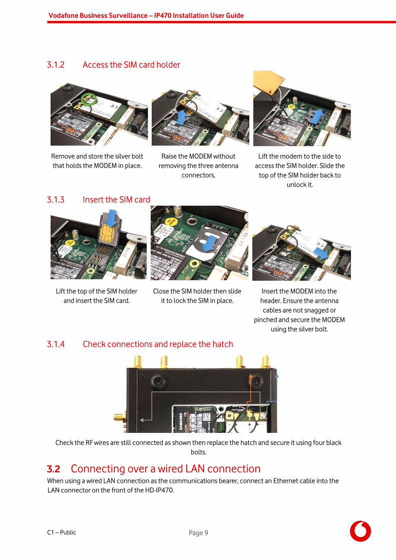
3.1.2 Access the SIM card holder
Remove and store the silver bolt
that holds the MODEM in place.
Raise the MODEM without
removing the three antenna
connectors.
Lift the modem to the side to
access the SIM holder. Slide the
top of the SIM holder back to
unlock it.
3.1.3 Insert the SIM card
Lift the top of the SIM holder
and insert the SIM card.
Close the SIM holder then slide
it to lock the SIM in place.
Insert the MODEM into the
header. Ensure the antenna
cables are not snagged or
pinched and secure the MODEM
using the silver bolt.
3.1.4 Check connections and replace the hatch
Check the RF wires are still connected as shown then replace the hatch and secure it using four black
bolts.
Connecting over a wired LAN connection When using a wired LAN connection as the communications bearer, connect an Ethernet cable into the
LAN connector on the front of the HD-IP470.
Vodafone Business Surveillance – IP470 Installation User Guide
C1 – Public Page 10
The encoder also includes a driver for the USB to Ethernet adapters using the Asix AX88772 chipset. Any
USB LAN Adapter that uses this chipset should be compatible with the encoder. Devices known to contain
the Asix AX88772 include:
Edimax EU-4028 USB 2.0 Fast Ethernet Adapter
Apple USB to Ethernet adapter
UtechSmart USB 2.0 to 10/100 Fast Ethernet LAN Wired Network Adapter
Vodafone Business Surveillance – IP470 Installation User Guide
C1 – Public Page 11
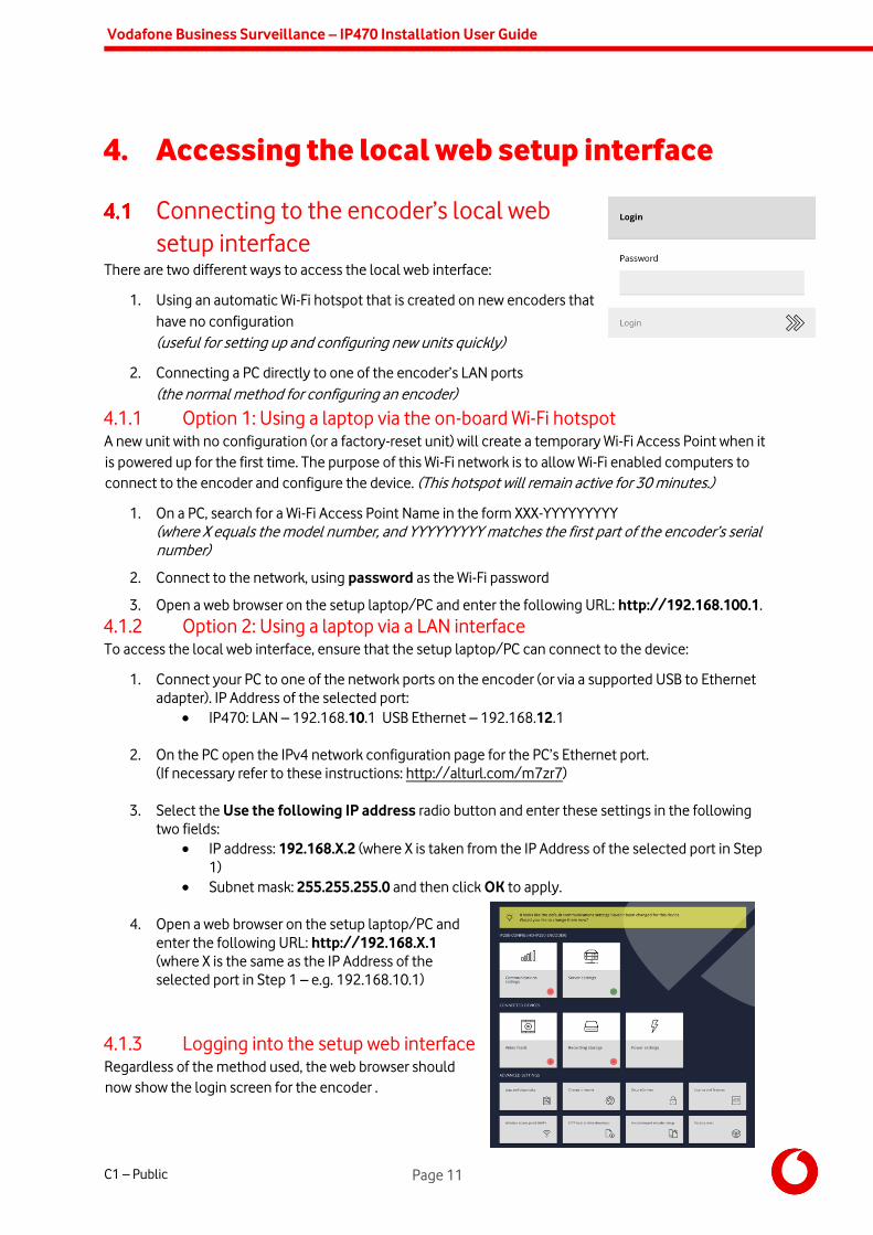
4. Accessing the local web setup interface
Connecting to the encoder’s local web
setup interface There are two different ways to access the local web interface:
1. Using an automatic Wi-Fi hotspot that is created on new encoders that
have no configuration
(useful for setting up and configuring new units quickly)
2. Connecting a PC directly to one of the encoder’s LAN ports
(the normal method for configuring an encoder)
4.1.1 Option 1: Using a laptop via the on-board Wi-Fi hotspot A new unit with no configuration (or a factory-reset unit) will create a temporary Wi-Fi Access Point when it
is powered up for the first time. The purpose of this Wi-Fi network is to allow Wi-Fi enabled computers to
connect to the encoder and configure the device. (This hotspot will remain active for 30 minutes.)
1. On a PC, search for a Wi-Fi Access Point Name in the form XXX-YYYYYYYYY
(where X equals the model number, and YYYYYYYYY matches the first part of the encoder’s serial
number)
2. Connect to the network, using password as the Wi-Fi password
3. Open a web browser on the setup laptop/PC and enter the following URL: http://192.168.100.1.
4.1.2 Option 2: Using a laptop via a LAN interface To access the local web interface, ensure that the setup laptop/PC can connect to the device:
1. Connect your PC to one of the network ports on the encoder (or via a supported USB to Ethernet
adapter). IP Address of the selected port:
IP470: LAN – 192.168.10.1 USB Ethernet – 192.168.12.1
2. On the PC open the IPv4 network configuration page for the PC’s Ethernet port.
(If necessary refer to these instructions: http://alturl.com/m7zr7)
3. Select the Use the following IP address radio button and enter these settings in the following
two fields:
IP address: 192.168.X.2 (where X is taken from the IP Address of the selected port in Step
1)
Subnet mask: 255.255.255.0 and then click OK to apply.
4. Open a web browser on the setup laptop/PC and
enter the following URL: http://192.168.X.1
(where X is the same as the IP Address of the
selected port in Step 1 – e.g. 192.168.10.1)
4.1.3 Logging into the setup web interface Regardless of the method used, the web browser should
now show the login screen for the encoder .

Vodafone Business Surveillance – IP470 Installation User Guide
C1 – Public Page 12
The default password is encoder name. (as included in the device kit / quick
start guide)
Once logged in the encoder’s dashboard is loaded:
The dashboard presents the status of the encoder, showing red-crosses where
an issue requires attention, or a green tick to indicate that section of encoder
configuration is operating correctly. The encoder will also display a help tip if
any crucial encoder settings are still blank and require configuration.

Vodafone Business Surveillance – IP470 Installation User Guide
C1 – Public Page 13
5. Overview of the key setup steps
Encoder is pre-configured to assistance with installation. There are four key steps in encoder configuration.
1. Configure the communications settings for LAN ports, cellular modem
2. Provide the details of Vodafone Business Surveillance server and encoder account
3. Add each desired video feed to the encoder
4. Select the desired recording location and encryption settings
This section describes each of these four key steps.
Step 1 – Configure the
communications settings The encoder can utilise both internal and external communications
devices. However we
There are four main tasks to perform in this section:
1. Enable and disable communications methods
2. Configure the settings for each communications bearer
3. Select the communications bearers to use to connect to
Vodafone Business Surveillance Server (both a primary and
secondary)
4. Enable a firewall on the primary/secondary communications bearers
5.1.1 Enable and disable comms methods For security reasons, it is recommended to disable any comms method that are not required. Click the
desired communications method and use the Enable/Disable this device menu item.

Vodafone Business Surveillance – IP470 Installation User Guide
C1 – Public Page 14
5.1.2 Configure each comms method’s settings For each comms method that will be used, click on its entry to view its settings, and from there use the
Edit configuration menu item to enter the settings.
Cellular
connection
Cellular connection will be pre-configured in IP470 with a preloaded Vodafone
SIM.
Cellular connections require an APN, username and password to connect to a
mobile data network – either enter these manually or select from the list of
common mobile operators.
Advanced options include:
Wireless IP address – some private APN networks may require an IP
address
Network Technology – force the modem to use 2G, 3G or 4G (or Auto
select)
Comms Technology – certain modems can work in either GSM or CDMA mode
LAN connection It is possible, on a per-LAN port basis, to set either DHCP (for connection to a
larger network) or a static configuration (usually for direct-connection to a
camera).
5.1.3 Select the preferred server comms method It is necessary to select the primary comms method that the encoder will
use to connect to Vodafone Business Surveillance Server and stream
content. A secondary method can be also specified for failover for periods
when the primary bearer is unavailable.
It is possible to set a primary or secondary method directly from the
Communication Settings page, or to use the Use for primary/secondary
communication menu item on each method’s settings page.
5.1.4 Enable the firewall on the primary/secondary comms methods The only services running on an encoder that are externally accessible are the encoder’s web configuration
page and, if enabled, the SFTP recordings download service. The default setting is to allow access to these
services on any communications method.
For security reasons, it is possible to remove access to these services on communications methods that
have been configured as primary/secondary communications methods. Use the Firewall Settings menu
item to block access to these services.
WARNING: You may immediately lose access to the web setup interface if you are currently configuring the unit
through the primary/secondary comms method and you enable the firewall – this should be the last step you
perform!

Vodafone Business Surveillance – IP470 Installation User Guide
C1 – Public Page 15
Step 2 - Enter the encoder’s Vodafone Business Surveillance
settings
NOTE: Before the encoder can be connected to a Vodafone Business Surveillance Server, it requires an encoder
account be created on Vodafone Business Surveillance Server. This step is typically undertaken by an administrator
and preconfigured in encoder.
To proceed a user must have the following details for an encoder:
The Domain Name of the user’s Vodafone Business Surveillance Server –
(surveillanceserver.iot.vodafone.com)
The name and password of the encoder account
created on Vodafone Business Surveillance Server
(Optionally) The encryption fingerprint of the
Vodafone Business Surveillance Server
The Server Settings page will display the current settings being
used to connect to the server, and the status of the connection.
To edit the server connection settings, use the Change server settings menu option and enter the details
above.
5.2.1 Encryption modes When connecting to Vodafone Business Surveillance Server it is possible to select one of three encryption
modes.
Encrypted (online verification)
The user will be asked to verify the encryption fingerprint of
Vodafone Business Surveillance Server before allowing a
connection
Unencrypted
In some circumstances the Vodafone Business Surveillance
Server may not support encryption and so this option should
be used
Encrypted (offline verification)
If connecting to the server is not currently possible to verify the fingerprint this option allows the
user to upload the Vodafone Business Surveillance Server’s encryption pack (available from
Vodafone Business Surveillance Server), which will subsequently be verified when the encoder
reconnects to the server
Encoder will be configured to connect to Vodafone Business Surveillance Server via Encrypted (Online
Verification) mode.

Vodafone Business Surveillance – IP470 Installation User Guide
C1 – Public Page 16
5.2.2 Encoder Licensing Encoders must also be licensed to connect to a Vodafone Business Surveillance Server. This can be done
during the account creation on Vodafone Business Surveillance Server or, if no licence has been assigned,
be requested by the encoder during configuration
In no licence is currently assigned the Server Settings page will provide a link where the user can request
a licence from the server (if available). The form will also show the features enabled within the selected
licence.
Step 3 - Adding video feeds to the encoder There are two main ways to add an IP camera:
FastConnect – designed to make it simple to add new cameras ‘out-of-the-box’ directly to an
encoder, without the need for the user to know the camera IP Address or configure the camera in
advance of connection.
Auto-Discover – designed for discovering cameras, either directly
connected to the encoder or through a LAN connection that has
already been configured with the correct network settings.
Consider the following questions when deciding which method to use:
FastConnect Auto-Discover
Who is it for? Users with new Axis, Bosch or
Canon cameras who are directly
connecting the camera to the
encoder
Users of a compatible camera who
have configured the camera to be on
the same network subnet as their
encoder
Suitable for one-to-one
connections between
camera and encoder? YES YES
Suitable for finding
cameras on a LAN
network?
NO YES
Supports adding more
than one camera per
port?
NO YES
Compatibility Axis, Bosch and Canon cameras
on the compatibility list
Any named camera on the camera
compatibility list

Vodafone Business Surveillance – IP470 Installation User Guide
C1 – Public Page 17
Prerequisites - Camera must have default IP
Address and default admin
password set.
- Camera must be connected
directly to the device.
- The LAN port configured for use
on the Series device must be set
for Static IP.
- Encoder LAN port in use can either
be set to static IP for direct
connection or configured to connect
to a LAN network.
- Camera must be pre-configured with
an IP Address that can be accessed by
the encoder (usually on the same
sub-net)
As the IP470s do not have an analog input, an analog to digital converter/encoder is needed, if a customer
requires them to be connected to an analog camera. Axis Single Channel Encoder is the recommended
converter for this solution. They can be powered over Ethernet or with an additional power source.
5.3.1 Adding an IP camera using FastConnect From the Camera Settings page click the Add button to start the Add
Camera wizard.
Select the Add a camera via FastConnect menu option.
Select the network interface the camera is directly attached
to.
Select the brand of camera you are adding to the encoder.
Enter a friendly name that Vodafone Business Surveillance
should use to refer to this camera
Enter a new administrator password for the IP camera
Please take note of both the new IP Address and password, as these
may be required later if configuring the camera through its web
configuration pages.
The next stage is for the encoder to then attempt to find the camera
attached to the device, and if found, will reconfigure the camera and
add it to the list of cameras connected to the encoder.
NOTE: This will only succeed if the camera has factory default settings,
including all network settings.
5.3.2 Auto discover a connected IP Camera For cameras that are not configured using FastConnect, it is recommended to search for the camera using
the Search local network for cameras menu option.
NOTE: The IP camera and the port (on the encoder) it is connected to must have compatible IP Address settings.
Usually this means that the IP Address of the camera, and address of the encoder port must both be 192.168.X.Y,
where X is the same, but Y is unique on the network.
The encoder will search all enabled network interfaces for IP cameras and display a list of all cameras
available.
To select a camera, click on its entry in the list.
Vodafone Business Surveillance – IP470 Installation User Guide
C1 – Public Page 18
This will then prompt for:
A friendly name that Vodafone Business Surveillance should use to refer to this camera
The login details of the camera (required for most cameras)
Whether to allow Vodafone Business Surveillance Client to access the camera’s web interface via
SecureConnect
Once entered the camera should now be added to the encoder’s list of video feeds.
If the desired camera is not listed in the discovered cameras, it may still be possible to add the camera, either
by reconfiguring the camera/encoder’s network settings to match or by adding the camera manually.
Appendix offers some advice and trouble-shooting tips if required.
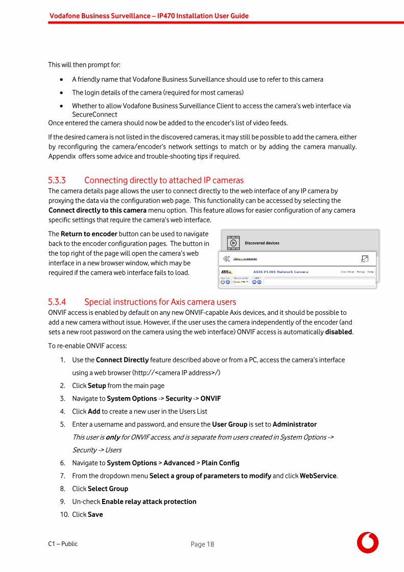
5.3.3 Connecting directly to attached IP cameras The camera details page allows the user to connect directly to the web interface of any IP camera by
proxying the data via the configuration web page. This functionality can be accessed by selecting the
Connect directly to this camera menu option. This feature allows for easier configuration of any camera
specific settings that require the camera’s web interface.
The Return to encoder button can be used to navigate
back to the encoder configuration pages. The button in
the top right of the page will open the camera’s web
interface in a new browser window, which may be
required if the camera web interface fails to load.
5.3.4 Special instructions for Axis camera users ONVIF access is enabled by default on any new ONVIF-capable Axis devices, and it should be possible to
add a new camera without issue. However, if the user uses the camera independently of the encoder (and
sets a new root password on the camera using the web interface) ONVIF access is automatically disabled.
To re-enable ONVIF access:
1. Use the Connect Directly feature described above or from a PC, access the camera’s interface
using a web browser (http://<camera IP address>/)
2. Click Setup from the main page
3. Navigate to System Options -> Security -> ONVIF
4. Click Add to create a new user in the Users List
5. Enter a username and password, and ensure the User Group is set to Administrator
This user is only for ONVIF access, and is separate from users created in System Options ->
Security -> Users
6. Navigate to System Options > Advanced > Plain Config
7. From the dropdown menu Select a group of parameters to modify and click WebService.
8. Click Select Group
9. Un-check Enable relay attack protection
10. Click Save

Vodafone Business Surveillance – IP470 Installation User Guide
C1 – Public Page 19
It should now be possible to add the Axis camera to the encoder.
Step 4 – Setting recording settings An encoder can save recordings to an internal or external USB Disk (Fat32 formatted, at least 20GByte, USB
3.0 preferred). External NAS Disk is supported as a beskope option.
Note: The maximum supported capacity on an internal or external hard drive is 2TB. It is possible to use larger drives,
but they must be formatted by the encoder and the recording space will be reduced to 2TB.
The Recording Storage page will list all available recording locations.
If multiple locations are available, the encoder will pool the locations to
increase the available storage duration.
The Storage Settings menu option can be used to configure various aspects of the
recording. For security reasons, it is possible to enable/disable individual types of
recording devices (or to turn off recording entirely).
When all storage devices become full it is possible to either:
Overwrite oldest recordings (default)
Stop recording
When stop recording is selected the encoder will start to send out notifications when
each disk starts to become full (the threshold is configurable).
To view the settings and status of a recording location select it from the list.
As well as showing the status of the device (including how full it is) it also allows the user to format the
drive, or safely eject the drive from the encoder.
Users wishing to use a NAS drive will require the Windows file share information:
The IP Address of the NAS (e.g. 192.168.10.12)
The name of the share (e.g. share)
The username/password to connect to the NAS
Recording drives can also be speed tested to determine if the storage
device is fast enough for recording purposes.
Vodafone Business Surveillance – IP470 Installation User Guide
C1 – Public Page 20
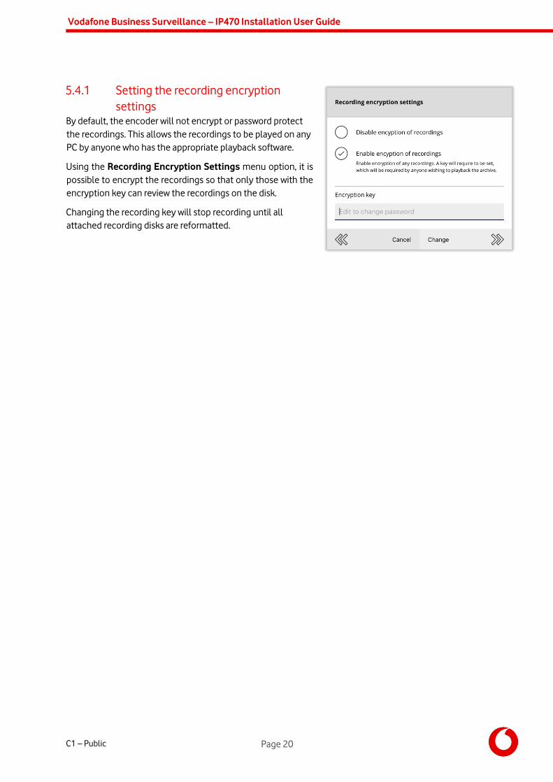
5.4.1 Setting the recording encryption
settings By default, the encoder will not encrypt or password protect
the recordings. This allows the recordings to be played on any
PC by anyone who has the appropriate playback software.
Using the Recording Encryption Settings menu option, it is
possible to encrypt the recordings so that only those with the
encryption key can review the recordings on the disk.
Changing the recording key will stop recording until all
attached recording disks are reformatted.

Vodafone Business Surveillance – IP470 Installation User Guide
C1 – Public Page 21
6. Roles and permissions
Introducing Role-based access control Vodafone Business Surveillance Server based on industry standard best practice, called Role-based Access
Control (RBAC) to regulate users’ access to the server, groups and encoders. Rather than assign individual
permissions to a user on a case-by-case basis, it is first necessary to create a Role that contains all the
desired permissions for a user, and assign that role to a user.
The permissions within Vodafone Business Surveillance Server fall into three different categories:
Server permissions
The ability to manage the server, including managing domains, server settings, backup/restore
and role editing
Account management
The ability to create/edit/delete groups, encoders and users
Encoder usage
The ability to control how encoders are configured and used within viewing clients
Each category has several sub-categories, each of which contain many granular permissions for each sub-
category. The following table outlines the different categories, sub-categories, and number of available
permissions within each.
Role
Contains one or more permissions from the following…
Server permissions
(Server-wide administrators only)
Account management
Encoder usage
Domain management
3 permissions
User role management
3 permissions
Server configuration
8 permissions
Backup/restore database
3 permissions
Encoder firmware
2 permissions
Manage group accounts
3 permissions
Manage encoder accounts
4 permissions
Manage user accounts
7 permissions
Viewing client permissions
19 permissions
Accessing edge recordings
4 permissions
Configure streaming
parameters
3 permissions
Encoder configuration
11 permissions
Encoder maintenance
2 permissions
There are four built-in roles (that can’t be modified or deleted):
Server Administrator– All permissions available within the system
Standard Administrator - Users within the Customer organisation performing admin tasks. These
roles has permissions within Account management and Encoder usage

Vodafone Business Surveillance – IP470 Installation User Guide
C1 – Public Page 22
Standard User - – Users within the Customer organisation performing standard tasks. All
permissions within Encoder usage (except Encoder configuration and Encoder maintenance)
Vodafone Administrator- System control by Vodafone and (or) 3rd party agents.
Note: Creating new roles in the platform is restricted to server administrator roles and not recommended
without product owner approval.
6.1.1 Creating a custom role Creating new roles in the platform is restricted to server administrator roles and not permitted without
product owner approval.
6.1.2 Assigning roles to users and defining the role scope Once a role has been selected for a user, the second decision an administrator must make is to decide the
scope the user has access to. There are four possible scopes:
Server-wide – the top level of the server, above all domains. A user granted a role at the server
level will have those permissions on any encoder/user/group in any domain in the system.
A specific domain – assigning a user a domain-wide role will grant them the appropriate
permissions on any encoder/user/group in the specified domain.
A specific group of encoders – to limit a user to only using/administering a group of specific
encoders
A specific encoder – to limit a user to only using/administering one specific encoder
For example, the following table describes the effects of assigning a user one of the built-in roles (Server
Administrator, Domain Administrator, Encoder Administrator or Viewer) to each of the different scopes
(Server-wide, a specific domain, and a specific group/encoder):
Role Scope Examples
The user is given the following permissions based on the following scopes…
Role
Server-wide A specific domain
A specific group or
encoder
Server
Administrator
All permissions available on
the server, on any domain
and on any group/encoder
(i.e. full access)
All permissions in the Account
Management and Encoder
usage section on…
any encoder/user in the
domain
All permissions in the Account
Management and Encoder
usage section on…
the specified group/encoder
Standard
Administrator
All permissions in the
Account Management and
Encoder usage section on…
any encoder/user on the
server
All permissions in the Account
Management and Encoder
usage section on…
any encoder/user in the
domain
All permissions in the Account
Management and Encoder
usage section on…
the specified group/encoder
Vodafone
Administrator
Can perform any Encoder
usage permission on…
any encoder on the server
Can perform any Encoder
usage permission on…
any encoder in the domain
All Encoder usage permissions
on…
the specified group/encoder

Vodafone Business Surveillance – IP470 Installation User Guide
C1 – Public Page 23
Standard
User
Can perform any viewer
permission on…
any encoder on the server
Can perform any viewer
permission on…
any encoder in the domain
Can perform any viewer
permission on…
the specified group/encoder
6.1.3 Assigning a server-wide role to a user
When to use: There is a requirement to either provide a user the ability to configure/monitor the server or
provide the user with a level of access to all domains, and groups/encoders/users within each domain.
Users with a server-wide role do not exist within any domain and can be viewed by selecting the Server
Administrators button on the server home page.
This will display a list of Server Administrators, including the default Administrator account. To view an
existing user’s details, including their assigned role, click on their name. To create a new user with a server-
wide role use the Create user menu option and enter a name and password – this will then display the
new user’s details.
The user’s detail page will display their
communication preferences and the role(s) they
have been assigned.
To add or change the roles, click the roles icon in
the Server Wide Access section (which may indicate that no roles are currently applied).
This will open the Manage user roles page which
will display the user’s existing roles.
The bottom section of the page lists all the roles
available on the system, which can be assigned to
the user by using the plus icon.
The middle section of the page lists the roles
assigned to the user. To remove a role, use the
delete icon.
To view the permissions a role will grant, click on
the role’s icon. This will display a summary of the
role, where it is possible to drill down into each
role’s categories and the individual permissions
within.
It is possible to assign multiple roles to a user, which creates an additive effect granting the user all the
permissions contained within each role.
Vodafone Business Surveillance – IP470 Installation User Guide
C1 – Public Page 24
6.1.4 Assigning a user role to a specific domain
When to use: There is a requirement to provide a user, within a specific domain, a level of access (for example
account management) to all groups/encoders/users within that domain.
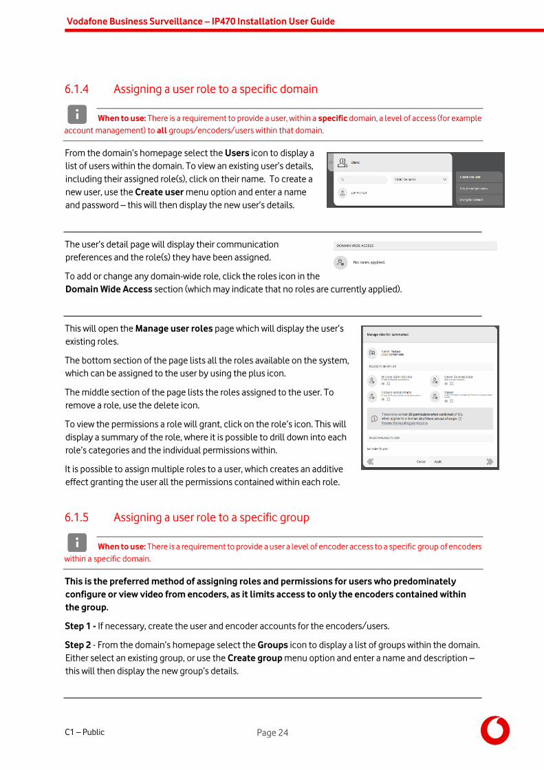
From the domain’s homepage select the Users icon to display a
list of users within the domain. To view an existing user’s details,
including their assigned role(s), click on their name. To create a
new user, use the Create user menu option and enter a name
and password – this will then display the new user’s details.
The user’s detail page will display their communication
preferences and the role(s) they have been assigned.
To add or change any domain-wide role, click the roles icon in the
Domain Wide Access section (which may indicate that no roles are currently applied).
This will open the Manage user roles page which will display the user’s
existing roles.
The bottom section of the page lists all the roles available on the system,
which can be assigned to the user by using the plus icon.
The middle section of the page lists the roles assigned to the user. To
remove a role, use the delete icon.
To view the permissions a role will grant, click on the role’s icon. This will
display a summary of the role, where it is possible to drill down into each
role’s categories and the individual permissions within.
It is possible to assign multiple roles to a user, which creates an additive
effect granting the user all the permissions contained within each role.
6.1.5 Assigning a user role to a specific group
When to use: There is a requirement to provide a user a level of encoder access to a specific group of encoders
within a specific domain.
This is the preferred method of assigning roles and permissions for users who predominately
configure or view video from encoders, as it limits access to only the encoders contained within
the group.
Step 1 - If necessary, create the user and encoder accounts for the encoders/users.
Step 2 - From the domain’s homepage select the Groups icon to display a list of groups within the domain.
Either select an existing group, or use the Create group menu option and enter a name and description –
this will then display the new group’s details.

Vodafone Business Surveillance – IP470 Installation User Guide
C1 – Public Page 25
The group’s detail page will display any existing encoders
and users in the group.
Use the In this group list box to toggle between showing
encoders and users in the group.
Step 3 – Use the Add encoder to group menu option to
select the desired encoder accounts to add to the group.
Step 4 – Use the Add user to group menu option and select the user.
It is possible to assign multiple roles to a user, which creates an additive effect granting the user all the
permissions (applicable to encoders) contained within each role.
Repeat Step 4 to add each user to the group.
6.1.6 Assigning a user role to a specific encoder
When to use: There is a requirement to provide a user a level of encoder access to an individual encoder
within a specific domain.
While it is possible to provide access to individual encoders it is the least flexible method of
managing roles. Using groups to manage roles allows for easier ongoing management of users
and encoders.
Step 1 - From the domain’s homepage select the Encoders icon to display a list of encoders within the
domain. Either select an existing encoder, or use the Create encoder menu option and enter a name and
password – this will then display the new encoder’s details.
The encoder’s detail page will display a number of configuration
icons within the Encoder configuration section, varying on
encoder model and online/offline status.
Step 2 – Use the Directly configured access icon to display the
list of groups and users who have access to the encoder.
Step 3 – Use the Add user to encoder menu option to select the existing user to grant access.
The user must already exist – if not return to the domain home page and create a new user first.
Vodafone Business Surveillance – IP470 Installation User Guide
C1 – Public Page 26
7. User Accounts
Vodafone Business Surveillance Server employs strict security rules, ensuring that before any user can
connect to the server they have the appropriate login credentials to the server - there is no concept of
guest or anonymous usage within Vodafone Business Surveillance. Once created a user account can then
be granted a level of access (e.g. a specific domain) and permissions to access resources within that level
(e.g. Encoder Administrator).
There are two kinds of users:
Server-wide Administrators
These users have server-wide access, and if given the appropriate role, can perform:
o Server administration and configuration
o Domain management
o Group, Encoder and User Account Management
o Encoder configuration
Domain Users
These users have specific access within a domain, and if given the appropriate role, can perform:
o Group, Encoder and User Account Management
o Encoder configuration
Given the server-wide access granted, in normal operation it would be expected to create a limited number
of Server Administrators. Normal users should be created within a domain, and only granted access to the
required encoders or account management permissions.
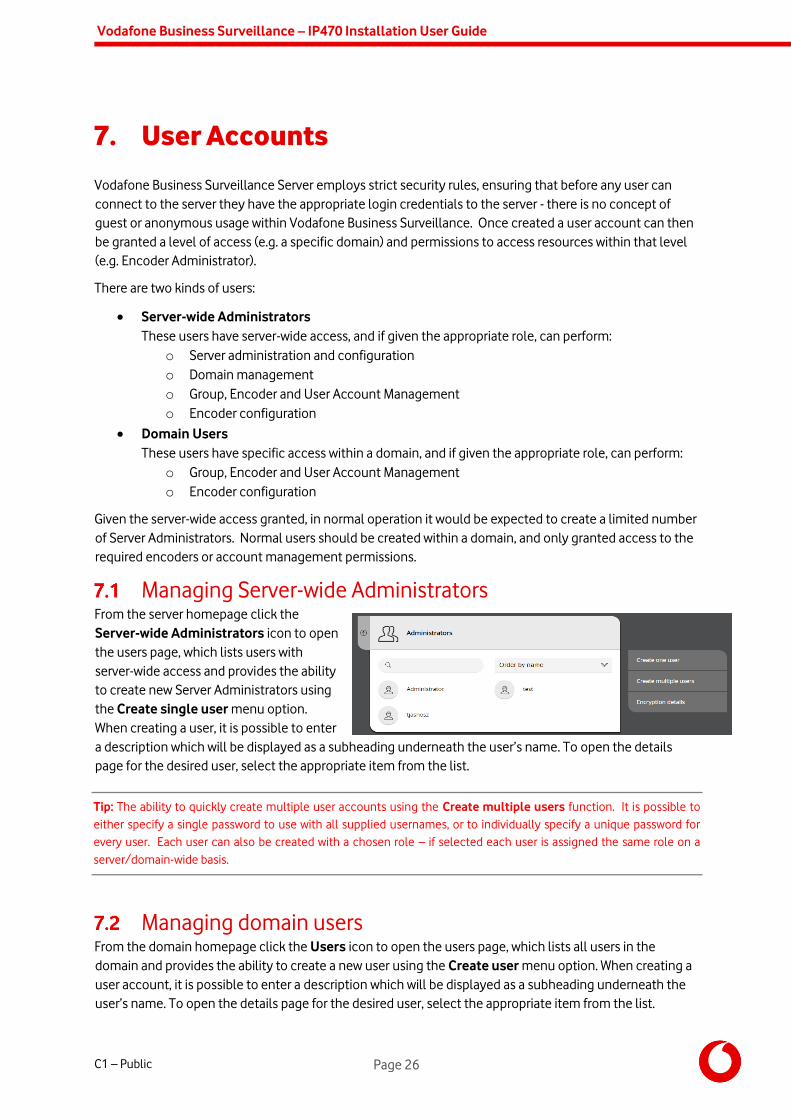
Managing Server-wide Administrators From the server homepage click the
Server-wide Administrators icon to open
the users page, which lists users with
server-wide access and provides the ability
to create new Server Administrators using
the Create single user menu option.
When creating a user, it is possible to enter
a description which will be displayed as a subheading underneath the user’s name. To open the details
page for the desired user, select the appropriate item from the list.
Tip: The ability to quickly create multiple user accounts using the Create multiple users function. It is possible to
either specify a single password to use with all supplied usernames, or to individually specify a unique password for
every user. Each user can also be created with a chosen role – if selected each user is assigned the same role on a
server/domain-wide basis.
Managing domain users From the domain homepage click the Users icon to open the users page, which lists all users in the
domain and provides the ability to create a new user using the Create user menu option. When creating a
user account, it is possible to enter a description which will be displayed as a subheading underneath the
user’s name. To open the details page for the desired user, select the appropriate item from the list.
Vodafone Business Surveillance – IP470 Installation User Guide
C1 – Public Page 27
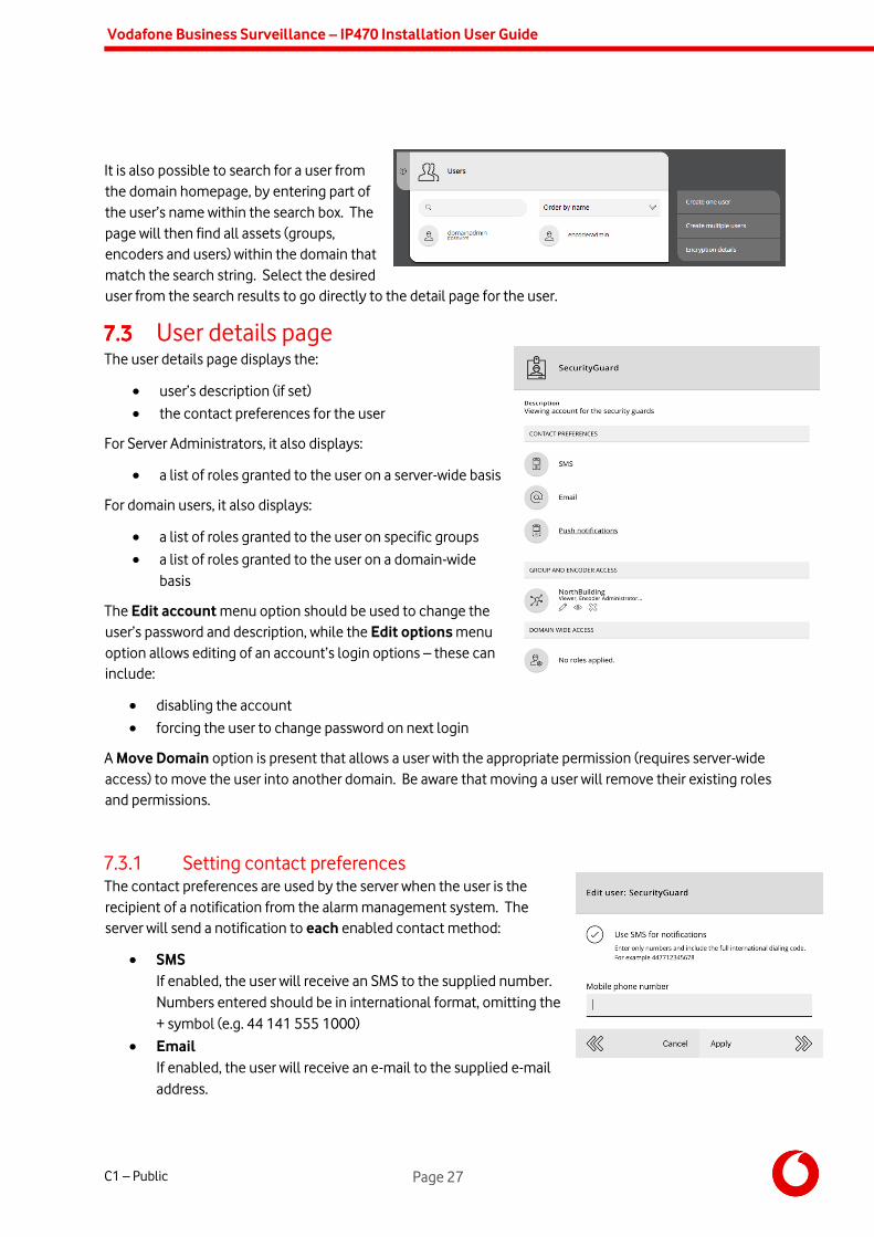
It is also possible to search for a user from
the domain homepage, by entering part of
the user’s name within the search box. The
page will then find all assets (groups,
encoders and users) within the domain that
match the search string. Select the desired
user from the search results to go directly to the detail page for the user.
User details page The user details page displays the:
user’s description (if set)
the contact preferences for the user
For Server Administrators, it also displays:
a list of roles granted to the user on a server-wide basis
For domain users, it also displays:
a list of roles granted to the user on specific groups
a list of roles granted to the user on a domain-wide
basis
The Edit account menu option should be used to change the
user’s password and description, while the Edit options menu
option allows editing of an account’s login options – these can
include:
disabling the account
forcing the user to change password on next login
A Move Domain option is present that allows a user with the appropriate permission (requires server-wide
access) to move the user into another domain. Be aware that moving a user will remove their existing roles
and permissions.
7.3.1 Setting contact preferences The contact preferences are used by the server when the user is the
recipient of a notification from the alarm management system. The
server will send a notification to each enabled contact method:
SMS
If enabled, the user will receive an SMS to the supplied number.
Numbers entered should be in international format, omitting the
+ symbol (e.g. 44 141 555 1000)
If enabled, the user will receive an e-mail to the supplied e-mail
address.

Vodafone Business Surveillance – IP470 Installation User Guide
C1 – Public Page 28
Push notifications
A user with an iOS or Android device who connects to the
server using Vodafone Business Surveillance Client will
automatically be registered for push notifications on that
device. Selecting the Push notifications icon will display
every device registered to receive notifications for that
user – the device will continue to receive notifications for
as long as the app is installed.
Un-tick devices to disable devices if required – for example
if the user has changed or lost a particular device.
7.3.2 Managing a user’s roles and permissions The bottom section of the user details page lists:
Server-wide Administrator accounts only
The Server Wide Access section displays the roles the user has been granted on a server-wide basis.
See ‘Assigning a server-wide role to a user’ for details on how to assign/change the user’s role.
Domain users accounts only
The Group and Encoder Access section displays the roles granted on a group basis (signified by the
group icon ), and on an individual encoder basis (signified by the encoder icon ).
See ‘Assigning a user role to a specific group’ for details on how to assign/change group roles.
See ‘Assigning a user role to a specific encoder’ for details on how to provide access to encoders.
It is also possible to add a user directly to a group from the user detail page using the Add to group menu
option.
The Domain Wide Access section lists the roles the user has been granted on a domain-wide basis
See ‘Assigning a user role to a specific domain’ for details on how to assign/change the user’s role.
It is security best-practice to only provide the minimum level of access required to any user. It is
recommended to only provide domain wide access to users who are required to manage the accounts
within a domain, and to use groups to provide access to users who use and manage encoders.

Vodafone Business Surveillance – IP470 Installation User Guide
C1 – Public Page 29
8. Additional configuration options
There are several additional configuration options available on the encoder’s home page:
Change time zone The time used by the encoder (for both live video and recordings) is automatically set by synchronising with
Vodafone Business Surveillance Server. The encoder saves all recordings in UTC (GMT), and during display
of both live video and recordings the viewing client will offset the time displayed by the time-zone
configured in this setting.
NTP Service Many IP cameras can display the current date/time overlayed on the video. To print the correct time, IP
cameras need an accurate time source – to help provide this the encoder can run an NTP (Network Time
Protocol) server to ensure that the encoder and all IP cameras use the same date and time.
The option to enable/disable NTP is available from the Time and date settings page. Once enabled it is
necessary to log in to each IP camera and configure it to use NTP as a time source. The address for the
NTP server should be the IP Address of the encoder’s LAN port (that it is connected to).
SecureConnect SecureConnect is a feature that allows IP cameras, video analytics and other edge devices to be remotely
configured and controlled using the secure Vodafone Business Surveillance architecture. This allows a
remote user to operate IP devices using Vodafone Business Surveillance Client.
The most common use case is to access the configuration web pages of attached IP cameras – and the
encoder can automatically add a SecureConnect channel for each camera when adding the camera to the
encoder.
The SecureConnect page displays all configured SecureConnect channels on the encoder, allowing the
user to add/edit/delete entries. Additionally, the user can decide how much of the configured streaming
bandwidth can be used by all SecureConnect users combined – the higher the bandwidth ratio, the lower
the amount of remaining bandwidth for video transmission.
For more information on SecureConnect please refer to the Knowledge Base Article: Using
SecureConnect to access remote devices.

Vodafone Business Surveillance – IP470 Installation User Guide
C1 – Public Page 30
9. Appendix A - Troubleshooting and
frequently asked questions
How many channels does the HD-IP470 support? The IP470 only supports 4 cameras connected with SafeZone2D, however the HD-IP470 can record up to
eight cameras and transmit one of those cameras. It is possible to create multiple quad-views allowing
four cameras to be transmitted simultaneously.
What level of recording and streaming performance is
achievable? Based on the processing power of the HD-IP470, the unit can achieve 25/30 fps of 1080p quality recording
whilst simultaneously streaming one 1080p video stream at close to 10fps (or 720p at 15fps).
What recording functions does the HD-IP470 support? The HD-IP470 can be set up to record continuously, or to record on an alarm trigger. Recordings can be
set to overwrite old recordings automatically, or to stop on full.
What indicative recording times and streaming rates are
achievable? The HD-IP470 records the incoming video stream from IP cameras without modification. By default,
cameras are automatically configured by the encoder to 1080p @ 25/30fps at a bitrate of 10 Mbps when
added to an encoder. This will provide approximately 8 days recordings at a very high quality (multiple
cameras will proportionally reduce this duration) on the supplied 1TB drive.
After adding the camera, and by using the camera’s own configuration interface, the user is usually able to
manually configure lower quality setting on their IP cameras to extend the duration of recordings if
necessary. This table provides an indication of the potential increase in duration possible:
Frame rate IP Camera b/w 1TB SDD
1 fps 1.4 Mbps 64 days
6.25 fps 3 Mbps 32 days
12.5 fps 5 Mbps 16 days
25 fps 7 Mbps 12 days
720p cameras are approximately half of the resolution of 1080p (and standard definition cameras are
approximately ¼ of the resolution of 1080p) and as such will use proportionally less data.

Vodafone Business Surveillance – IP470 Installation User Guide
C1 – Public Page 31
What bearers can the HD-IP470 use to transmit video to
EdgeVis Server? The HD-IP470 includes an inbuilt 4G/LTE cellular modem for efficient streaming over commercially
available cellular networks. It can also transmit using its inbuilt LAN port or Wi-Fi module. EdgeVis
optimises its transmission to the characteristics of the bearer that it is being used to maximise
performance.
How does EdgeVis Server licensing work in relation to the
HD-IP470? The EdgeVis Server licensing model is based on the number of cameras connected to the encoder. An HD-
IP470 unit therefore requires up to eight encoder licences for licensing purposes (if all eight cameras are
being utilised). These licences must either be of type EdgeVis Lite, Enhanced or Enterprise, depending on
the feature set desired.
What web browser can I use for the setup? A web browser with JavaScript enabled and HTML5 compatible is required. The encoder’s web interface
should work with Internet Explorer 10+ and the latest versions of Microsoft Edge, Firefox, Chrome and
Safari.
What if I need to restore the encoder to default factory
settings? It is possible to factory reset an encoder. Create an empty file called FACTORY_RESET on a blank USB Flash Drive
and insert it into a powered encoder. After approximately 30 seconds the encoder should be reset to factory defaults.
Default password is ‘password’.
What if the encoder can’t connect to my Vodafone Business
Surveillance Server? An encoder will only connect to the Vodafone Business Surveillance Server once all stages of the setup
process have been completed.
If all the stages have been completed the home page should show green ticks for communication and
server settings to signify the encoder is now connected to the server and is available for viewing. The
following checklist should provide some guidance if the encoder does not connect to the server:
• Confirm the encoder account created in Vodafone Business Surveillance Server matches the account on the
encoder, and that the appropriate licence has been allocated to the encoder account.
• Ensure the IP address/domain name for the Vodafone Business Surveillance Server is correct and that the
server is accessible from the internet
• Try disabling server encryption (if it is enabled) to ensure that it is not an encryption pack issue
• Cellular users should ensure that the right SIM slot has been used and that the configured APN settings are
correct. Test the SIM card with a smart phone to check the SIM settings and confirm there is a mobile signal
• LAN/Wi-Fi users should ensure the network that the encoder is configured to use is connected to the Internet
If this list does not help, try some alternative settings to try and narrow down the issue. For example, using
a different encoder account, Vodafone Business Surveillance Server or communications bearer to
eliminate server/comms/account issues.
Vodafone Business Surveillance – IP470 Installation User Guide
C1 – Public Page 32
10. Appendix B - Troubleshooting camera
discovery issues
What makes and models of IP camera does the encoder
support? IP470 only has two camera drivers; ONVIF or RTSP, and only H.264 is supported.
The ONVIF driver has been tested with a wide range of cameras (including those from Axis, Bosch, Canon
and Panasonic).
What if I cannot see my camera listed when I search for
cameras? Unfortunately, auto-discovery can sometimes fail to find a camera. This can be for a number of reasons:
• The IP camera and the encoder do not have compatible IP addresses
Check that they are on the same subnet, but do not have the same IP address
IP cameras are also mini-computers that can take time to boot up (often several minutes)
Allow the camera time to boot up before the auto-discovery process – or reboot if it has crashed
The IP camera may not be a supported device
Review the camera model against the IP470 Camera Compatibility List
The firmware on the IP camera may be out of date and causing an issue
Check the version of firmware that is installed on your IP camera and update if required
If the encoder is still unable to find the IP camera automatically, try adding the camera manually. Use the
Add camera manually menu option and enter its IP address/login details manually.
What if I cannot successfully add the IP camera? If the camera will not add (and provide a ‘green tick’), or is not available to preview, the following check list
provides some guidance on how to fix this issue:
If the camera uses PoE for power, check that the camera is receiving power from the encoder. If
possible, try to power the camera independently during testing to eliminate PoE issues.
Ensure the camera is booted up and available by allowing at least 30-120 seconds for it to ‘warm
up’
Try restarting the camera in case it has crashed
Delete and add the camera again, confirming the username and password is correct
If multiple services are offered while adding the camera try selecting an alternative video service
Plug the camera into a different network and log into it directly to confirm it is operating correctly
and can be connected on the IP Address. ONVIF Device Manager is a free open source tool that
can be used to view the video feed from the camera.
Vodafone Business Surveillance – IP470 Installation User Guide
C1 – Public Page 33
What if I don’t know the IP address (or login details) of my IP
camera? The simplest way to overcome the loss of any details for an IP camera is to download the manual for the camera, which
should provide instructions on resetting the IP camera to its factory settings and obtaining the factory configured IP
address, username and password. With the default camera details in hand, it should then be possible to connect the
camera to the encoder and enter the correct details.
Setting the IP address on a camera to function with an
encoder To modify the IP settings on a camera, refer to the instructions from the camera manufacturer. These will
outline how to log into the camera (using a PC/laptop), which will require the username and password for
the camera. If unavailable, refer to instructions for performing a factory reset (note that it may be necessary
to download a setup application from the manufacturer). It is important to note that any Power-over-
Ethernet (PoE) cameras must be connected to a laptop/PC via a PoE switch to both connect to, and power
the camera.
After logging into the IP camera, it will be possible to set the IP address within the ranges compatible with
the encoder. Note that each camera connected to an encoder must have a different IP address to avoid
conflicts.
Setting the IP address of a port to function with an existing
camera To connect a camera to an encoder device without modifying the camera’s settings, the IP address of the
corresponding port will need modified to be on the same subnet as the camera. For example, if the IP address
of the camera is 192.168.54.11, the IP address of the port would be entered as 192.168.54.X, where X is any
number in the range between 2 and 254. The subnet mask for the port should be entered as 255.255.255.0.
What if my IP camera supports multiple video streams? If the IP camera can supply multiple video feeds (e.g. the Axis F44 supports four independent camera
sensors) the encoder will detect this and present a list of available ONVIF ‘sources’ that the camera offers.
The names listed are supplied by the camera - it may not be immediately obvious which service relates to
each camera.
If it is not possible to determine the camera from the name listed, it is recommended to add each service
in turn and use the Preview video feed menu option (within the camera settings page) to determine
which service provides each video feed.
Camera Compatibility Guide These are the named cameras that we recommend to use with IP-Series encoders.
Manufacturer Model Camera
Firmware H.264 PTZ
PTZ Preset
Focus Iris
Axis P1214 5.40.12.2 Pass N/A N/A N/A N/A
Axis P1365 5.75.2 Pass N/A N/A N/A N/A

Vodafone Business Surveillance – IP470 Installation User Guide
C1 – Public Page 34
Axis P5515 6.40.1 Pass Pass Pass N/A N/A
Axis Q6034 5.41.1 Pass Pass Pass N/A N/A
Axis Q3505-VE 5.75.2 Pass N/A N/A N/A N/A
Axis Q7404 5.50.2 Pass Pass Pass N/A N/A
Axis M3114 5.40.9.3 Pass N/A N/A N/A N/A
Axis M1054 5.50.3 Pass N/A N/A N/A N/A
Axis M1025 5.40.5 Pass N/A N/A N/A N/A
Axis M5014 5.50.3 Pass Pass Pass N/A N/A
Axis M7011 5.75.1 Pass Pass Pass N/A N/A
Axis F41 5.65.2 Pass N/A N/A N/A N/A
Axis F44 5.85.3 Pass N/A N/A N/A N/A
Bosch AutoDome Easy II IP 5.72 Pass Pass Pass N/A N/A
Bosch
FlexiDome HD 720p RD IVA 5.6 Pass N/A N/A N/A N/A
Bosch VIP X 1600B 4.21 Pass N/A N/A N/A N/A
Bosch Autodome JR 800 HD 5.73 Pass Pass Pass N/A N/A
Bosch NDC-284-PT 6.10.0129 Pass N/A N/A N/A N/A
Bosch IP 5000 HD 6.22.0007 Pass Pass Pass N/A N/A
Canon H41 1.3.0 Pass Pass Pass Pass Pass
Canon H43 1.2.5 Pass Pass Pass Pass Pass
Canon H610D 1.1.0 Pass N/A N/A N/A N/A
Canon R11 Pass Pass Pass Pass Pass
Samsung SNP-5200H 2.23 Pass Pass Pass Pass Pass
Samsung SNB-5000P 3.24_140701 Pass N/A N/A N/A N/A
Samsung SNP-3120 3.24_140701 Pass N/A N/A N/A N/A
Panasonic SP105E 2.1 Pass N/A N/A N/A N/A
Panasonic SC385 2.02 Pass Pass Pass N/A N/A
Sony CH110 1.85.00 Pass N/A N/A N/A N/A
Cisco IPC-6050 2.5.0-10 Pass N/A N/A N/A N/A
Indigo Vision BX500HD 3.3.0.2 Pass Pass Pass Pass Pass

Vodafone Business Surveillance – IP470 Installation User Guide
C1 – Public Page 35
11. Appendix C – Vehicle Installation
The HD-IP470 unit is designed for in-vehicle deployment.
Dimensions and fixings for in-vehicle installation Ensure that you have adequate space to install the HD-IP470 mounting plate and unit with access to the
camera inputs, antenna connections and removable storage device on the front plate. The 8~35V battery
input power connection is located on the side of the unit and this should be factored in when siting the
unit in a vehicle.
To install the mounting plate, remove and retain the bolts holding the rubber feet to the unit. Remove the
rubber feet. Install the mounting plate and secure it by replacing the bolts though into the base of the
encoder.
Connecting the HD-IP470 to a vehicle battery
The HD-IP470 can be powered directly from a vehicle battery – either a 12V or 24V
power source.
When installing in a vehicle, the following connections must be made to the power
input connectors on the rear of the unit:
Connect negative to the contact marked ‘GND‘ on the DC input connector.
Connect positive to the contact marked ‘V+’ on the DC Input connector.
Connect ignition line to the contact marked ‘IGN’ on the DC Input connector.
Note: the unit will power up 10 seconds after the IGN switch is connected and will
switch off 10 seconds after the IGN switch is disconnected.

Vodafone Business Surveillance – IP470 Installation User Guide
C1 – Public Page 36
12. Appendix D – Technical Specification and
connectors
FRONT: POWER Bulkhead Connector: 3-pin
Cable Connector: 9-pin
Note:
The system accepts DC input in the range 8V to 35V via a 3-pin connector. The screw
clamping mechanism on the terminal block offers additional connection reliability when
wiring DC power.
The following precautions must be taken to avoid damage to the unit:
DO NOT CONNECT DIRECTLY TO THE MAINS SUPPLY
Always ensure the supply is within the specified voltage range and employ suitable
filtering if voltage spikes are likely
Do not reverse the polarity of the DC power supply. It will cause irreparable damage to the
HD-IP470
Always provide a common ground between the HD-IP470 unit and all connected
equipment
V+ 8V – 35V
GND NC
IGN
Ignition command
line, connect to V+
line to signal the
unit to power on.
SIDE: COM1 Bulkhead Connector: 9-pin D-Sub Male
Cable Connector: 9-pin D-Sub Female
1 DCD
2 RX
3 TX
4 DTR
5 GND
6 DSR
7 RTS
8 CTS
9 RI
SIDE: COM2/3/4 Bulkhead Connector: 9-pin D-Sub Male
Cable Connector: 9-pin D-Sub Female
Note:
All pins marked NC are reserved for future use. Do not connect these pins.
1 -
2 COM2 RX
3 COM2 TX
4 NC
5 GND
6 NC
7 NC
8 NC
9 -
SIDE: DIO Bulkhead Connector: 15-pin D-Sub Female
Cable Connector: 15-pin D-Sub Male
Note:
All pins marked NC are reserved for future use. Do not connect these pins.
The input voltage for logic high is 5V – 24V, and the input voltage for logic low is 0V –
1.5V.
1 D_INPUT_0
2 D_INPUT_1
3 D_INPUT_GND
4 NC
5 NC
6 NC
7 NC
8 VDD
9 D_INPUT_GND
10 D_INPUT_2

Vodafone Business Surveillance – IP470 Installation User Guide
C1 – Public Page 37
11 D_INPUT_3
12 NC
13 NC
14 NC
15 -
FCC COMPLIANCE
This equipment has been tested and found to comply with the limits of a Class B digital device, pursuant to Part 15 of the FCC Rules. These limits are
designed to provide reasonable protection against harmful interference in a residential installation. This equipment generates, uses and can radiate radio
frequency energy and, if not installed and used in accordance with instructions, may cause harmful interference to radio communications. If this equipment
does cause harmful interference to radio or television reception, which can be determined by turning the equipment off and on, the user is encouraged to
try to correct the interference by one or more of the following:
Reorient or relocate the receiving antenna
Increase the separation between the equipment and receiver
Connect the equipment to an outlet on a circuit different from that to which the receiver is connected
The EdgeVis HD-IP470 unit may contain a radio module that has been FCC Approved for fixed and mobile applications (FCC ID: N7NMC7455 Contains
transmitter module IC: 2417C-MC7455 where 2417C-MC73542417C-MC7355 is the module’s certification number).
The EdgeVis HD-IP470 unit may contain a radio module that has been FCC Approved for fixed and mobile applications (FCC ID: PD97260H).
FCC Warning: changes or modifications not expressly approved by the party responsible for compliance could void the user's authority to operate the
equipment.
To meet the FCC’s RF exposure rules and regulations:
The use of a non-shielded interface cable with the EdgeVis HD-IP470 Encoder device is prohibited
The antenna(s) used with the EdgeVis HD-IP470 unit must be installed to provide a separation distance of at least 20cm (8 inches) from all
persons and must not be co-located or operating in conjunction with any other antenna or transmitter
The antenna(s) used with the EdgeVis HD-IP470 unit the antenna gain, including cable loss, must not exceed 6 dBi at 700 MHz, 850 MHz, 1700
MHz and 1900 MHz; 9 dBi at 2500/2600 MHz; and 1 dBi at 2300 MHz, as defined in 2.1091 for satisfying RF exposure compliance.
The EdgeVis HD-IP470 unit shall only be used for fixed and mobile applications.
CE COMPLIANCE STATEMENT The EdgeVis HD-IP470 Encoder complies with the following European Union Directives:
Low Voltage Directive LVD 2014/35/EU (Standards: EN 60950-1:2006+A11:2009+A1:2010+A12:2011+A2:2013)
Electromagnetic Compatibility EMC 2014/30/EU Annex II (Standards: EN 55032:2015, EN 61000-3-2: 2014, EN 61000-3-3: 2013, EN 55024:
2010+A1: 2015)
The Encoder contains a radio module that has been approved for integration into fixed and mobile applications. In order to satisfy the requirements for
integrating the radio module the unit is compliant with the following standards:
Radio Spectrum, Standard: EN 301 908-1, EN 301 908-2 V6.2.1, EN 301 908-13 V6.2.1
Electromagnetic Compatibility EMC 2014/30/EU Annex II (Standards: EN 55032:2015, EN 61000-3-2: 2014, EN 61000-3-3: 2013, EN 55024:
2010+A1: 2015)
Low Voltage Directive LVD 2014/35/EU (Standards: EN 60950-1:2006+A11:2009+A1:2010+A12:2011+A2:2013)
The Encoder contains a radio module that has been approved for integration into fixed and mobile applications. In order to satisfy the requirements for
integrating the radio module the unit is compliant with the following standards:
Health and Safety (Art 3(1) (a)): EN 62368-1: 2014, EN 62311:2008
EMC (Art.3(1) (b)): EN 201 489-1 v2.2.0 (draft), EN 301 489-17 v3.2.0 (draft)
Spectrum (Art.3(2)): EN 300 328 v2.1.1, EN 301 893 v2.1.1
RoHS2 Directive 2011/65/EU: EN 50581:2012
The use of this product may be dangerous and has to be avoided in the following areas:
Where it can interfere with other electronic devices in environments such as hospitals, airports, aircraft, etc.
Where there is risk of explosion such as gasoline stations, oil refineries, etc.
The user must ensure that:
The antenna(s) used with the EdgeVis HD-IP470 unit must be installed to provide a separation distance of at least 20cm from all persons and
must not be co-located or operating in conjunction with any other antenna or transmitter
The antenna(s) used with the EdgeVis HD-IP470 unit must conform to the requirements stated in the installation guide
The EdgeVis HD-IP470 unit shall only be used for fixed and mobile applications
It is responsibility of the user to enforce the country regulations and specific environment regulations.

Vodafone Business Surveillance – IP470 Installation User Guide
C1 – Public Page 38
13. Next steps…
After completing the steps contained within the previous sections you should have an IP470 encoder connected to a Vodafone Business Surveillance Server. This section outlines the steps you should take next.
Installing a viewing client Once the encoder is configured and connected to Vodafone Business Surveillance Server the next step is to
install Vodafone Business Surveillance Client to allow remote access to the video from the encoder.
Vodafone Business Surveillance Client is available on Windows, iOS or Android, and can be downloaded
directly from the Vodafone Support Site, along with the Vodafone Business Surveillance Client Quick
Start Guide.
Configuring the streaming parameters Once the encoder is configured and connected to Vodafone Business Surveillance Server, it is possible to
perform a more in-depth configuration of the unit using Vodafone Business Surveillance Server’s web
configuration interface. Refer to the Vodafone Business Surveillance Server Setup Guide for further
details.

Vodafone Business Surveillance – IP470 Installation User Guide
C1 – Public Page 39
www.vodafone.com/business
Vodafone Group 2020. This document is issued by Vodafone in confidence and is not to be reproduced in whole or
in part without the prior written permission of Vodafone. Vodafone and the Vodafone logos are trademarks of the
Vodafone Group. Other product and company names mentioned herein may be the trademarks of their respective
owners. The information contained in this publication is correct at time of going to print. Such information may be
subject to change, and services may be modified supplemented or withdrawn by Vodafone without prior notice. All
services are subject to terms and conditions, copies of which may be obtained on request.