woodworking - etp woodworking eng_20… · 7 benefits and features • fit your tools quick and...
TRANSCRIPT
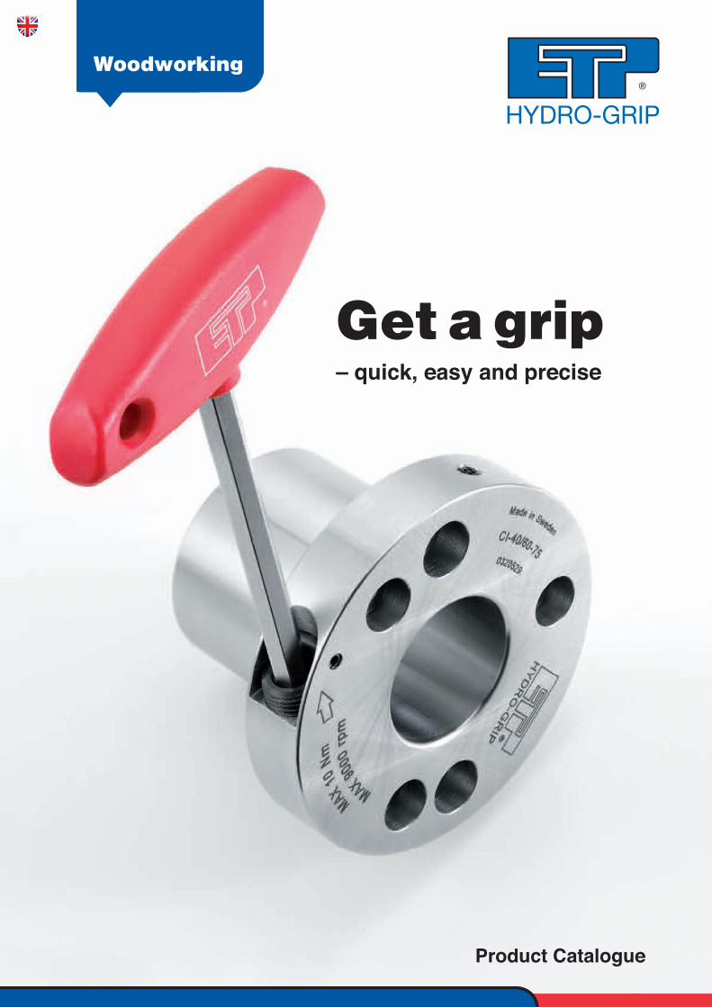
Getagrip– quick, easy and precise
Product Catalogue
Woodworking
2
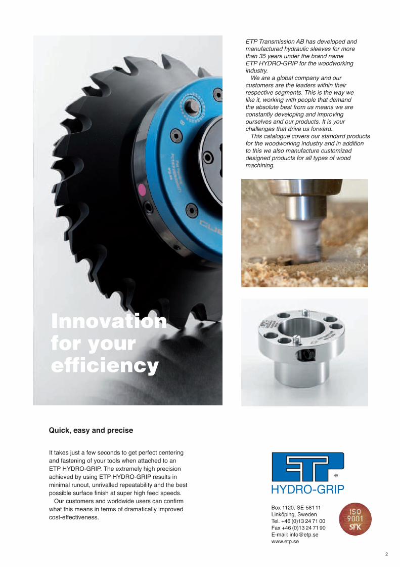
It takes just a few seconds to get perfect centering
and fastening of your tools when attached to an
ETP HYDRO-GRIP. The extremely high precision
achieved by using ETP HYDRO-GRIP results in
minimal runout, unrivalled repeatability and the best
possible surface finish at super high feed speeds.
Our customers and worldwide users can confirm
what this means in terms of dramatically improved
cost-effectiveness.
Quick, easy and precise
Innovation for your efficiency
Box 1120, SE-58111
Linköping, Sweden
Tel. +46 (0)13 24 71 00
Fax +46 (0)13 24 71 90
E-mail: [email protected]
www.etp.se
ETP Transmission AB has developed and manufactured hydraulic sleeves for more than 35 years under the brand name ETP HYDRO-GRIP for the woodworking industry.
We are a global company and our customers are the leaders within their respective segments. This is the way we like it, working with people that demand the absolute best from us means we are constantly developing and improving ourselves and our products. It is your challenges that drive us forward.
This catalogue covers our standard productsfor the woodworking industry and in addition to this we also manufacture customized designed products for all types of wood machining.
3
Table of content Page
678-91011
1314-151617
192021
2223
25-2627-3031-3334
3637
3940
41-43
44-45
4Pressurizing and assembly ...................
Sleeves for general woodworkingpressurizing with allen T-wrenchCI ...................................................................CIR ................................................................CUBIT mini ....................................................BI ...................................................................AI ...................................................................
Sleeves for general woodworkingpressurizing with high pressure pumpC ....................................................................B ....................................................................A ....................................................................AH .................................................................
Sleeves for tools with large internaldiametersCL ..................................................................BL ..................................................................AL ..................................................................
Sleeves for support bearingsDI ..................................................................D ...................................................................
Sleeves for floor manufacturing andprofilingCUBIT ...........................................................EI2, EI ..........................................................AEI ...............................................................AI ..................................................................
Hydraulic chucksG2 .................................................................G3 .................................................................
Hydraulic arborsGEW2 for Power Lock ...................................GE2 ...............................................................
Accessories ..............................................
Technical information ...........................
4
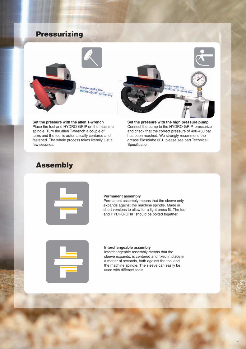
Set the pressure with the allen T-wrenchPlace the tool and HYDRO-GRIP on the machinespindle. Turn the allen T-wrench a couple of turns and the tool is automatically centered andfastened. The whole process takes literally just afew seconds.
Set the pressure with the high pressure pumpConnect the pump to the HYDRO-GRIP, pressurizeand check that the correct pressure of 400-450 barhas been reached. We strongly recommend thegrease Blasolube 301, please see part TechnicalSpecification.
Pressurizing
Assembly
Permanent assemblyPermanent assembly means that the sleeve onlyexpands against the machine spindle. Made inshort versions to allow for a light press fit. The tooland HYDRO-GRIP should be bolted together.
Interchangeable assemblyInterchangeable assembly means that thesleeve expands, is centered and fixed in place ina matter of seconds, both against the tool andthe machine spindle. The sleeve can easily beused with different tools.

Sleeves for generalwoodworking pressurizing withallen T-wrench
5Photo courtesy of Drömtrappor®, Emma 4.G.1 from Trätrappor AB
6
Benefits and features
• Fit your tools quick and easy
• Perfect centering and fastening with
only an allen T-wrench
• Easy to operate
• Probably the most durable pressurizing
mechanism on the market
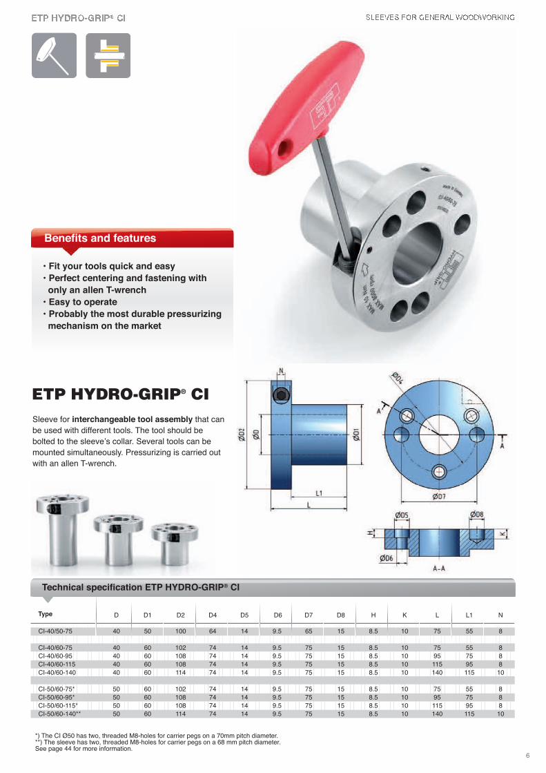
D D1 D2 D4 D5 D6 D7 D8 H K L L1 N
CI-40/50-75 40 50 100 64 14 9.5 65 15 8.5 10 75 55 8
CI-40/60-75 40 60 102 74 14 9.5 75 15 8.5 10 75 55 8
CI-40/60-95 40 60 108 74 14 9.5 75 15 8.5 10 95 75 8
CI-40/60-115 40 60 108 74 14 9.5 75 15 8.5 10 115 95 8
CI-40/60-140 40 60 114 74 14 9.5 75 15 8.5 10 140 115 10
CI-50/60-75* 50 60 102 74 14 9.5 75 15 8.5 10 75 55 8
CI-50/60-95* 50 60 108 74 14 9.5 75 15 8.5 10 95 75 8
CI-50/60-115* 50 60 108 74 14 9.5 75 15 8.5 10 115 95 8
CI-50/60-140** 50 60 114 74 14 9.5 75 15 8.5 10 140 115 10
Type
Technical specification ETP HYDRO-GRIP® CI
*) The CI Ø50 has two, threaded M8-holes for carrier pegs on a 70mm pitch diameter. **) The sleeve has two, threaded M8-holes for carrier pegs on a 68 mm pitch diameter.See page 44 for more information.
Sleeve for interchangeable tool assembly that can
be used with different tools. The tool should be
bolted to the sleeve’s collar. Several tools can be
mounted simultaneously. Pressurizing is carried out
with an allen T-wrench.
ETP HYDRO-GRIP® CI
7
Benefits and features
• Fit your tools quick and easy
• Stainless steel
• Can be ultrasonically cleaned
• Practical handling with flat
balance surface
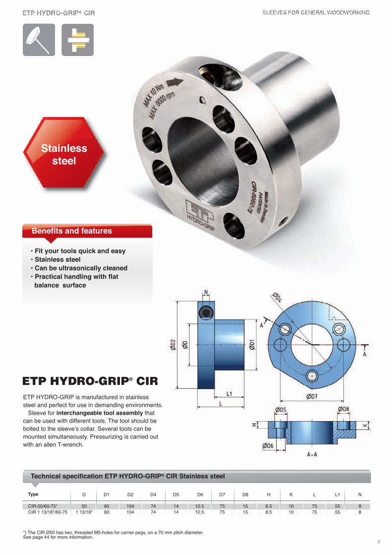
Stainless steel
D D1 D2 D4 D5 D6 D7 D8 H K L L1 N
CIR-50/60-75* 50 60 104 74 14 10.5 75 15 8.5 10 75 55 8
CIR 1 13/16"/60-75 1 13/16" 60 104 74 14 10.5 75 15 8.5 10 75 55 8
Type
Technical specification ETP HYDRO-GRIP® CIR Stainless steel
*) The CIR Ø50 has two, threaded M5-holes for carrier pegs, on a 70 mm pitch diameter. See page 44 for more information.
ETP HYDRO-GRIP is manufactured in stainless
steel and perfect for use in demanding environments.
Sleeve for interchangeable tool assembly that
can be used with different tools. The tool should be
bolted to the sleeve’s collar. Several tools can be
mounted simultaneously. Pressurizing is carried out
with an allen T-wrench.
ETP HYDRO-GRIP® CIR
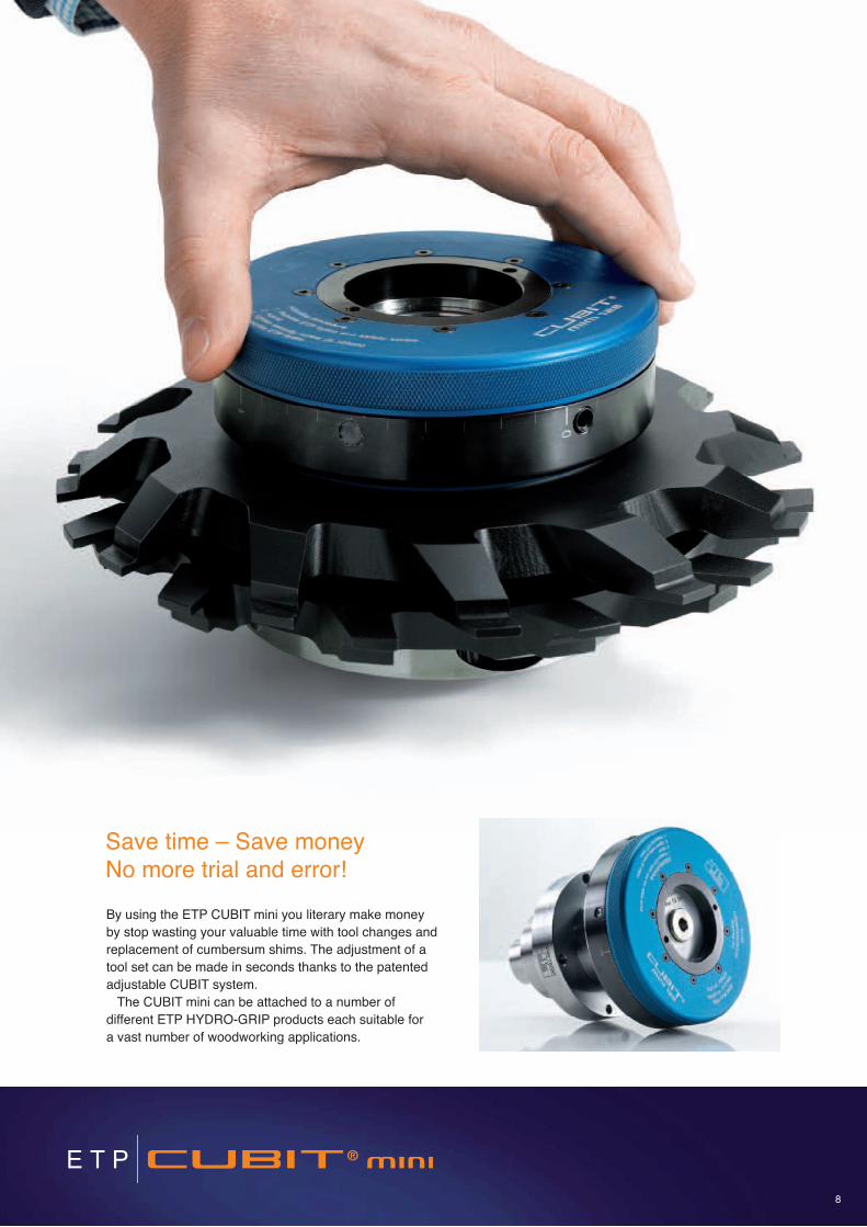
By using the ETP CUBIT mini you literary make money
by stop wasting your valuable time with tool changes and
replacement of cumbersum shims. The adjustment of a
tool set can be made in seconds thanks to the patented
adjustable CUBIT system.
The CUBIT mini can be attached to a number of
different ETP HYDRO-GRIP products each suitable for
a vast number of woodworking applications.
8
Save time – Save money No more trial and error!
2
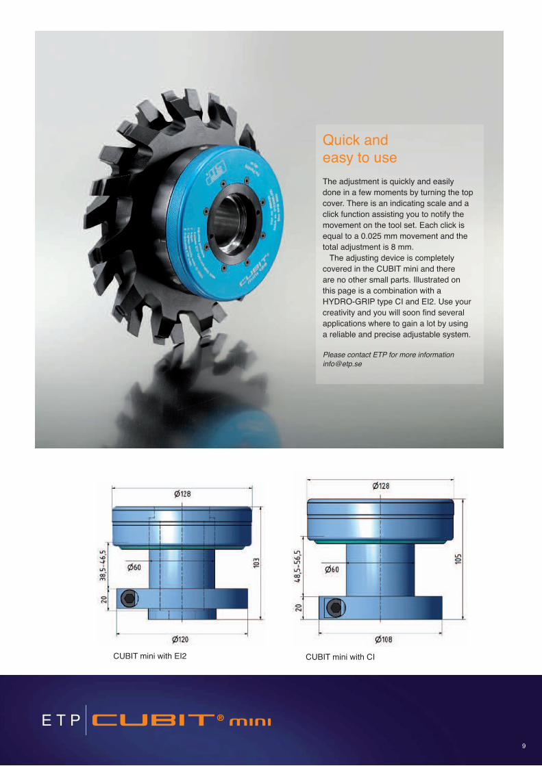
Quick and easy to use
The adjustment is quickly and easily
done in a few moments by turning the top
cover. There is an indicating scale and a
click function assisting you to notify the
movement on the tool set. Each click is
equal to a 0.025 mm movement and the
total adjustment is 8 mm.
The adjusting device is completely
covered in the CUBIT mini and there
are no other small parts. Illustrated on
this page is a combination with a
HYDRO-GRIP type CI and EI2. Use your
creativity and you will soon find several
applications where to gain a lot by using
a reliable and precise adjustable system.
Please contact ETP for more information
CUBIT mini with EI2 CUBIT mini with CI
9
10
Multiple tools
applications
ETP HYDRO-GRIP® BI
D D1 D2 D3 D4 D5 D6 D7 D8 H K L L1 L2 N
BI-40/50-75 40 50 100 83 64 14 9.5 65 15 8.5 10 75 40 55 8
BI-40/60-75 40 60 102 90 74 14 9.5 75 15 8.5 10 75 40 55 8
BI-40/60-95 40 60 108 90 74 14 9.5 75 15 8.5 10 95 60 75 8
BI-40/60-115 40 60 108 90 74 14 9.5 75 15 8.5 10 115 80 95 8
BI-50/60-75* 50 60 102 90 74 14 9.5 75 15 8.5 10 75 40 55 8
BI-50/60-95* 50 60 108 90 74 14 9.5 75 15 8.5 10 95 60 75 8
BI-50/60-115* 50 60 108 90 74 14 9.5 75 15 8.5 10 115 80 95 8
BI-1 1/2"/50-85 1 1/2" 50 100 83 64 14 9.5 65 15 8.5 10 85 50 65 8
BI-1 1/2"/50-135 1 1/2" 50 106 83 64 14 9.5 65 15 8.5 10 135 100 115 8
BI-1 13/16"/60-75 1 13/16" 60 102 90 74 14 9.5 75 15 8.5 10 75 40 55 8
BI-1 13/16"/60-115 1 13/16" 60 108 90 74 14 9.5 75 15 8.5 10 115 80 95 8
BI-1 13/16"/60-140 1 13/16" 60 114 90 74 14 9.5 75 15 8.5 10 140 105 120 8
BI-1 13/16"/65-85 1 13/16" 65 108 98 80 14 9.5 80 15 8.5 10 85 50 65 8
BI-2 1/8"/65-85 2 1/8" 65 108 98 80 14 9.5 80 15 8.5 10 85 50 65 8
Type
Technical specification ETP HYDRO-GRIP® BI
*) The BI Ø50 has two, threaded M8-holes for carrier pegs, on a 70 mm pitch diameter. See page 44 for more information.
Sleeve for interchangeable tool assembly, the
same basic construction as the CI but also has a
thread and locking nut. This means the sleeve can be
easily switched between different tools. Several tools
can be mounted to the same sleeve.
Pressurizing is carried out with an allen T-wrench.
Benefits and features
• Fit your tools quick and easy
several tools can be mounted on
the same sleeve
• Perfect centering and fastening
with only an allen T-wrench
• Same durable pressurizing
mechanism as CI
11
D D1 D2 D4 D5 D6 D7 D8 H K L L1 N
AI-40/50-55 40 50 83 64 10 6 65 15 5.5 10 55 35 6
AI-40/60-55 40 60 93 74 14 9.5 75 15 8.5 10 55 35 6
AI-50/60-55* 50 60 93 74 14 9.5 75 15 8.5 10 55 35 6
AI-50/60-75* 50 60 93 74 14 9.5 75 15 8.5 10 75 55 6
AI-50/65-75 50 65 98 80 14 9.5 80 15 8.5 10 75 55 6
AI-1 1/4"/40-55** 1 1/4" 40 83 55 14 9.5 55 15 8.5 10 55 35 6
AI-1 1/2"/50-55 1 1/2" 50 93 64 14 9.5 65 15 8.5 10 55 35 6
AI-1 13/16"/60-55 1 13/16" 60 93 74 14 9.5 75 15 8.5 10 55 35 6
AI-2 1/8"/65-55 2 1/8" 65 98 80 14 9.5 80 15 8.5 10 55 35 6
Type
Technical specification ETP HYDRO-GRIP® AI
*) The AI Ø50 has two, threaded M8 holes for carrier pegs, on a 70 mm pitch diameter.
**) The AI-1 1/4"/40 has two tool fastening holes.
See page 44 for more information.
Benefits and features
• Made in short lengths
• Light press fit
• Pressurizing is carried out
with an allen T-wrench
ETP HYDRO-GRIP® AISleeve for permanent tool assembly. Made in
short lengths to allow for a light press fit. Heat
up the tool before mounting. The tool and
HYDRO-GRIP should be bolted together.
Pressurizing is carried out with an allen T-wrench.

Sleeves for general woodworkingpressurizing with highpressure pump
12
13
Sleeve for interchangeable tool assembly which
can easily be switched between different tools. The
tool is fastened to the sleeve by bolts through the
collar. Several tools can be mounted simultaneously
on the same sleeve. Pressurizing is carried out with
a high pressure grease pump. This allows the use
of longer sleeves.
D D1 D2 D4 D5 D6 D7 D8 H K L L1
C-40/60-75 40 60 93 74 14 9.5 75 15 8.5 10 75 55
C-40/60-95 40 60 93 74 14 9.5 75 15 8.5 10 95 75
C-40/60-115 40 60 93 74 14 9.5 75 15 8.5 10 115 95
C-40/60-165 40 60 93 74 14 9.5 75 15 8.5 10 165 145
C-45/60-75* 45 60 93 74 14 9.5 70 M8 8.5 75 55
C-50/60-55* 50 60 93 74 14 9.5 75 15 8.5 10 55 35
C-50/60-75* 50 60 93 74 14 9.5 75 15 8.5 10 75 55
C-50/60-95* 50 60 93 74 14 9.5 75 15 8.5 10 95 75
C-50/60-115* 50 60 93 74 14 9.5 75 15 8.5 10 115 95
C-50/60-140* 50 60 93 74 14 9.5 75 15 8.5 10 140 120
C-50/60-190* 50 60 93 74 14 9.5 75 15 8.5 10 190 170
C-50/60-230* 50 60 93 74 14 9.5 75 15 8.5 10 230 210
C-60/70-75** 60 70 105 86 14 9.5 85 15 8.5 10 75 55
C-60/70-233 60 70 105 86 15 9.5 85 15 9 10 233 213
C-1 1/2"/50-85 1 1/2" 50 83 64 14 9.5 65 15 8.5 10 85 65
C-1 13/16"/60-75 1 13/16" 60 93 74 14 9.5 75 15 8.5 10 75 55
C-1 13/16"/65-85 1 13/16" 65 98 80 14 9.5 80 15 8.5 10 85 65
C-1 13/16"/65-135 1 13/16" 65 98 80 14 9.5 80 15 8.5 10 135 115
Type
Technical specification ETP HYDRO-GRIP® C
Benefits and features
• Several tools can be mounted on
the same sleeve
• Reduces set up time
• Pressurizing is carried out with
a high pressure pump
• Allows design with longer sleeves
ETP HYDRO-GRIP® C
*) The sleeve has two, threaded M8-holes for carrier pegs, on a 70 mm pitch diameter. **) The sleeve has two, threaded M8-holes for carrier pegs, on a 85 mm pitch diameter. See page 44 for more information.
14
Sleeve for interchangeable tool assembly, the same
basic construction as the BI with a thread and locking
nut. This means the sleeve can be easily switched
between different tools. Several tools can be mounted
to the same sleeve. Pressurizing is carried out with a
high pressure grease pump. This allows the use of
longer sleeves.
Traditionally
wide range
Benefits and features
• Well establish design with thread
and locking nut
• Several tools can be mounted on
the same sleeve
• Perfect centering and fastening
• Pressurizing is carried out with
a high pressure pump
ETP HYDRO-GRIP® B
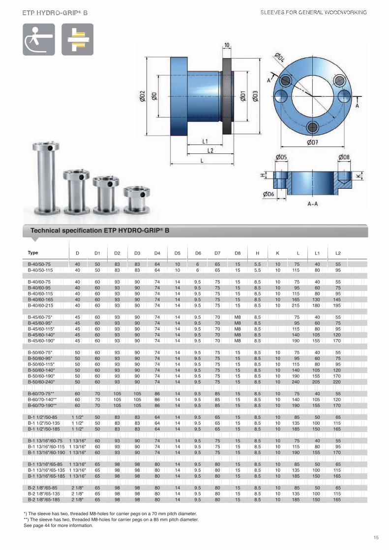
15
D D1 D2 D3 D4 D5 D6 D7 D8 H K L L1 L2
B-40/50-75 40 50 83 83 64 10 6 65 15 5.5 10 75 40 55
B-40/50-115 40 50 83 83 64 10 6 65 15 5.5 10 115 80 95
B-40/60-75 40 60 93 90 74 14 9.5 75 15 8.5 10 75 40 55
B-40/60-95 40 60 93 90 74 14 9.5 75 15 8.5 10 95 60 75
B-40/60-115 40 60 93 90 74 14 9.5 75 15 8.5 10 115 80 95
B-40/60-165 40 60 93 90 74 14 9.5 75 15 8.5 10 165 130 145
B-40/60-215 40 60 93 90 74 14 9.5 75 15 8.5 10 215 180 195
B-45/60-75* 45 60 93 90 74 14 9.5 70 M8 8.5 75 40 55
B-45/60-95* 45 60 93 90 74 14 9.5 70 M8 8.5 95 60 75
B-45/60-115* 45 60 93 90 74 14 9.5 70 M8 8.5 115 80 95
B-45/60-140* 45 60 93 90 74 14 9.5 70 M8 8.5 140 105 120
B-45/60-190* 45 60 93 90 74 14 9.5 70 M8 8.5 190 155 170
B-50/60-75* 50 60 93 90 74 14 9.5 75 15 8.5 10 75 40 55
B-50/60-95* 50 60 93 90 74 14 9.5 75 15 8.5 10 95 60 75
B-50/60-115* 50 60 93 90 74 14 9.5 75 15 8.5 10 115 80 95
B-50/60-140* 50 60 93 90 74 14 9.5 75 15 8.5 10 140 105 120
B-50/60-190* 50 60 93 90 74 14 9.5 75 15 8.5 10 190 155 170
B-50/60-240* 50 60 93 90 74 14 9.5 75 15 8.5 10 240 205 220
B-60/70-75** 60 70 105 105 86 14 9.5 85 15 8.5 10 75 40 55
B-60/70-140** 60 70 105 105 86 14 9.5 85 15 8.5 10 140 105 120
B-60/70-190** 60 70 105 105 86 14 9.5 85 15 8.5 10 190 155 170
B-1 1/2"/50-85 1 1/2" 50 83 83 64 14 9.5 65 15 8.5 10 85 50 65
B-1 1/2"/50-135 1 1/2" 50 83 83 64 14 9.5 65 15 8.5 10 135 100 115
B-1 1/2"/50-185 1 1/2" 50 83 83 64 14 9.5 65 15 8.5 10 185 150 165
B-1 13/16"/60-75 1 13/16" 60 93 90 74 14 9.5 75 15 8.5 10 75 40 55
B-1 13/16"/60-115 1 13/16" 60 93 90 74 14 9.5 75 15 8.5 10 115 80 95
B-1 13/16"/60-190 1 13/16" 60 93 90 74 14 9.5 75 15 8.5 10 190 155 170
B-1 13/16"/65-85 1 13/16" 65 98 98 80 14 9.5 80 15 8.5 10 85 50 65
B-1 13/16"/65-135 1 13/16" 65 98 98 80 14 9.5 80 15 8.5 10 135 100 115
B-1 13/16"/65-185 1 13/16” 65 98 98 80 14 9.5 80 15 8.5 10 185 150 165
B-2 1/8"/65-85 2 1/8" 65 98 98 80 14 9.5 80 15 8.5 10 85 50 65
B-2 1/8"/65-135 2 1/8" 65 98 98 80 14 9.5 80 15 8.5 10 135 100 115
B-2 1/8"/65-185 2 1/8" 65 98 98 80 14 9.5 80 15 8.5 10 185 150 165
Type
Technical specification ETP HYDRO-GRIP® B
*) The sleeve has two, threaded M8-holes for carrier pegs on a 70 mm pitch diameter.
**) The sleeve has two, threaded M8-holes for carrier pegs on a 85 mm pitch diameter.
See page 44 for more information.
16
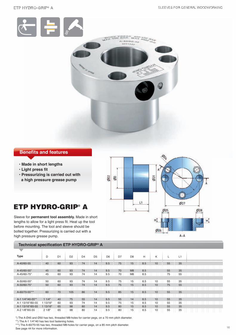
Sleeve for permanent tool assembly. Made in short
lengths to allow for a light press fit. Heat up the tool
before mounting. The tool and sleeve should be
bolted together. Pressurizing is carried out with a
high pressure grease pump.
D D1 D2 D4 D5 D6 D7 D8 H K L L1
A-40/60-55 40 60 93 74 14 9.5 75 15 8.5 10 55 35
A-45/60-55* 45 60 93 74 14 9.5 70 M8 8.5 55 35
A-45/60-75* 45 60 93 74 14 9.5 70 M8 8.5 75 55
A-50/60-55* 50 60 93 74 14 9.5 75 15 8.5 10 55 35
A-50/60-75* 50 60 93 74 14 9.5 75 15 8.5 10 75 55
A-60/70-55*** 60 70 105 86 14 9.5 85 15 8.5 10 55 35
A-1 1/4"/40-55** 1 1/4" 40 75 55 14 9.5 55 14 8.5 10 55 35
A-1 13/16"/60-55 1 13/16" 60 93 74 14 9.5 75 15 8.5 10 55 35
A-1 13/16"/65-55 1 13/16" 65 98 80 14 9.5 80 15 8.5 10 55 35
A-2 1/8"/65-55 2 1/8" 65 98 80 14 9.5 80 15 8.5 10 55 35
Type
Technical specification ETP HYDRO-GRIP® A
*) The A Ø45 and Ø50 has two, threaded M8-holes for carrier pegs, on a 70 mm pitch diameter.
**) The A-1 1/4"/40 has two tool fastening holes.
***) The A-60/70-55 has two, threaded M8-holes for carrier pegs, on a 85 mm pitch diameter.
See page 44 for more information.
ETP HYDRO-GRIP® A
Benefits and features
• Made in short lengths
• Light press fit
• Pressurizing is carried out with
a high pressure grease pump
17
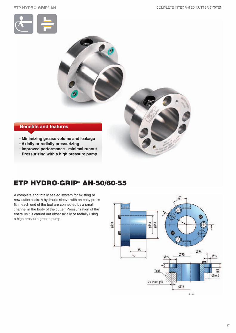
A complete and totally sealed system for existing or
new cutter tools. A hydraulic sleeve with an easy press
fit in each end of the tool are connected by a small
channel in the body of the cutter. Pressurization of the
entire unit is carried out either axially or radially using
a high pressure grease pump.
ETP HYDRO-GRIP® AH-50/60-55
Benefits and features
• Minimizing grease volume and leakage
• Axially or radially pressurizing
• Improved performance - minimal runout
• Pressurizing with a high pressure pump
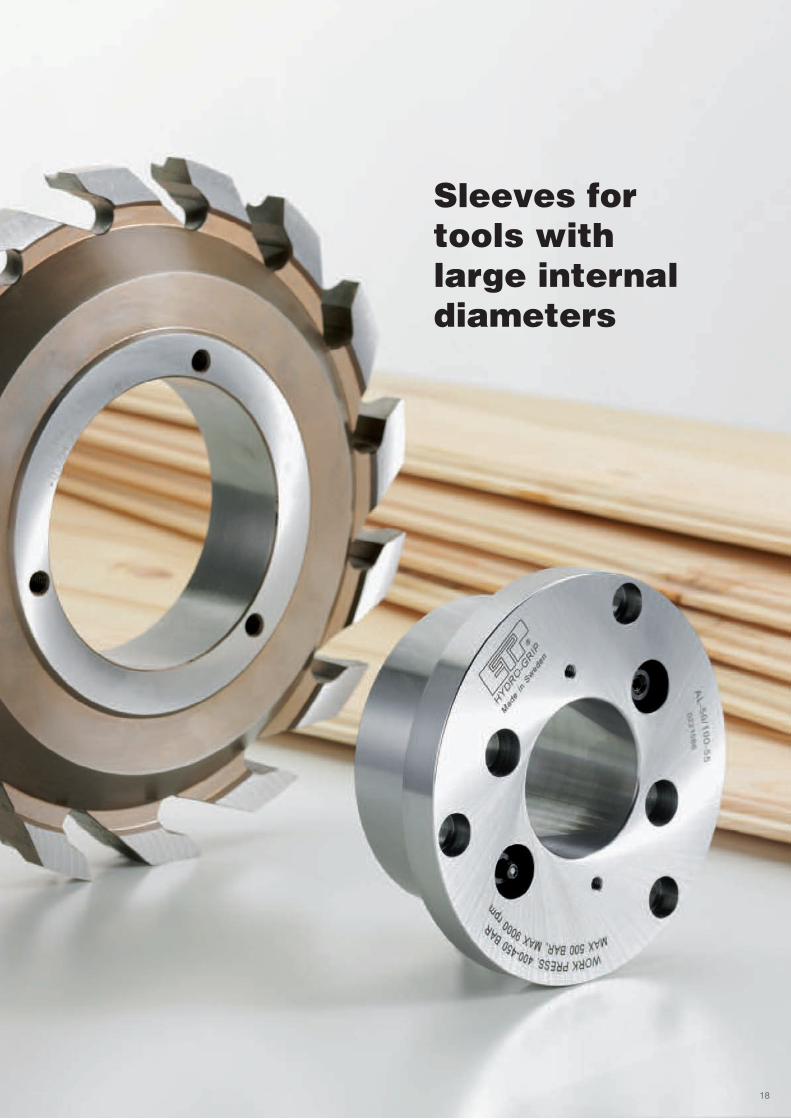
Sleeves for tools with large internaldiameters
18
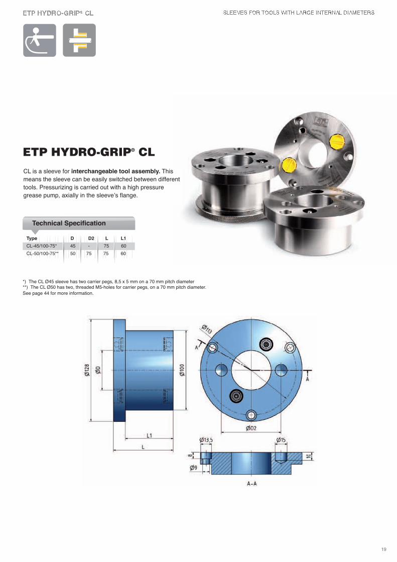
*) The CL Ø45 sleeve has two carrier pegs, 8,5 x 5 mm on a 70 mm pitch diameter**) The CL Ø50 has two, threaded M5-holes for carrier pegs, on a 70 mm pitch diameter.
See page 44 for more information.
ETP HYDRO-GRIP® CL
Type D D2 L L1
Technical Specification
CL-45/100-75* 45 - 75 60
CL-50/100-75** 50 75 75 60
CL is a sleeve for interchangeable tool assembly. This
means the sleeve can be easily switched between different
tools. Pressurizing is carried out with a high pressure
grease pump, axially in the sleeve’s flange.
19
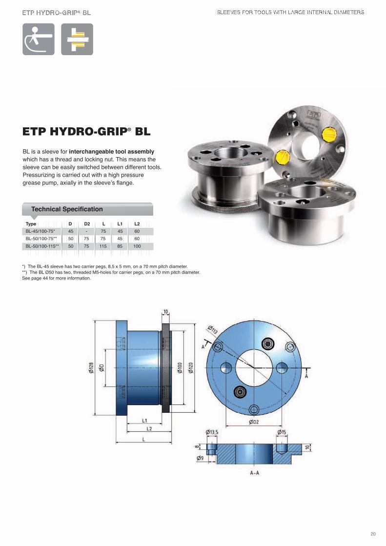
ETP HYDRO-GRIP® BL
BL is a sleeve for interchangeable tool assembly
which has a thread and locking nut. This means the
sleeve can be easily switched between different tools.
Pressurizing is carried out with a high pressure
grease pump, axially in the sleeve’s flange.
*) The BL-45 sleeve has two carrier pegs, 8,5 x 5 mm, on a 70 mm pitch diameter.
**) The BL Ø50 has two, threaded M5-holes for carrier pegs, on a 70 mm pitch diameter.
See page 44 for more information.
Type D D2 L L1 L2
Technical Specification
BL-45/100-75* 45 - 75 45 60
BL-50/100-75** 50 75 75 45 60
BL-50/100-115** 50 75 115 85 100
20
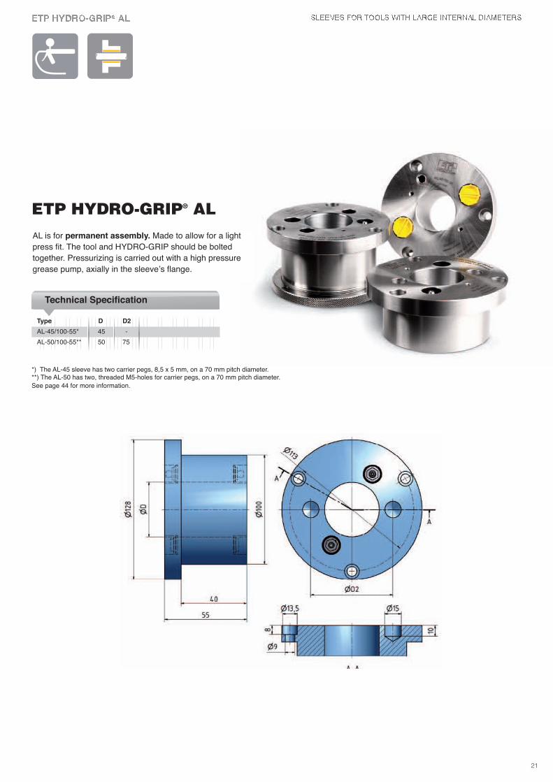
ETP HYDRO-GRIP® ALAL is for permanent assembly. Made to allow for a light
press fit. The tool and HYDRO-GRIP should be bolted
together. Pressurizing is carried out with a high pressure
grease pump, axially in the sleeve’s flange.
*) The AL-45 sleeve has two carrier pegs, 8,5 x 5 mm, on a 70 mm pitch diameter.**) The AL-50 has two, threaded M5-holes for carrier pegs, on a 70 mm pitch diameter.
See page 44 for more information.
Type D D2
Technical Specification
AL-45/100-55* 45 -
AL-50/100-55** 50 75
21
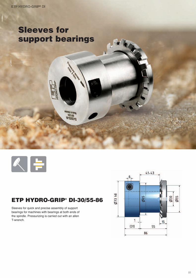
Sleeves for quick and precise assembly of support
bearings for machines with bearings at both ends of
the spindle. Pressurizing is carried out with an allen
T-wrench.
ETP HYDRO-GRIP® DI-30/55-86
Sleeves for support bearings
22
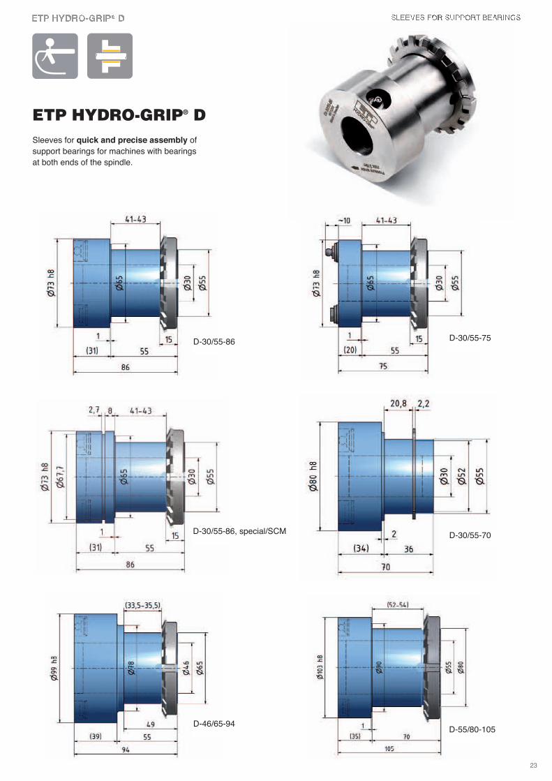
Sleeves for quick and precise assembly of
support bearings for machines with bearings
at both ends of the spindle.
ETP HYDRO-GRIP® D
D-30/55-70
D-30/55-86 D-30/55-75
D-30/55-86, special/SCM
D-46/65-94D-55/80-105
23

Sleeves for floor manufacturing and profiling
24
The ultimateway to profileprecision
25
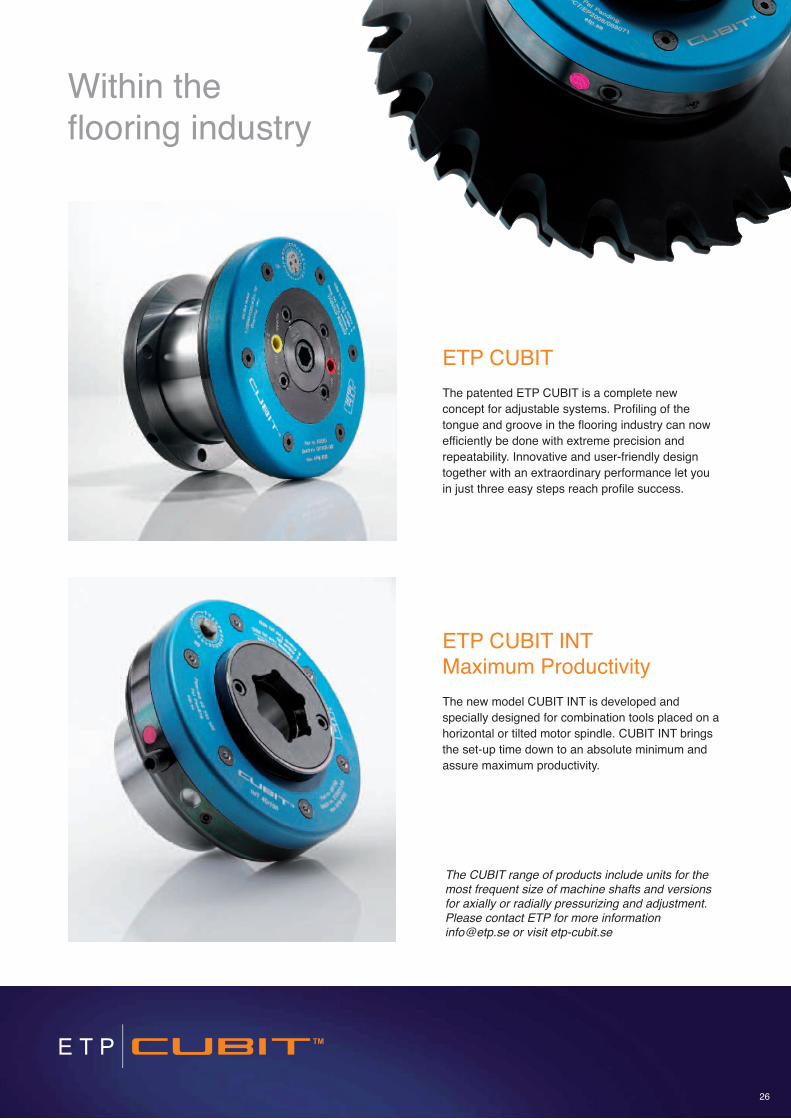
ETP CUBIT
The patented ETP CUBIT is a complete new
concept for adjustable systems. Profiling of the
tongue and groove in the flooring industry can now
efficiently be done with extreme precision and
repeatability. Innovative and user-friendly design
together with an extraordinary performance let you
in just three easy steps reach profile success.
ETP CUBIT INT Maximum Productivity
The new model CUBIT INT is developed and
specially designed for combination tools placed on a
horizontal or tilted motor spindle. CUBIT INT brings
the set-up time down to an absolute minimum and
assure maximum productivity.
Within the flooring industry
The CUBIT range of products include units for themost frequent size of machine shafts and versionsfor axially or radially pressurizing and adjustment.Please contact ETP for more [email protected] or visit etp-cubit.se
26
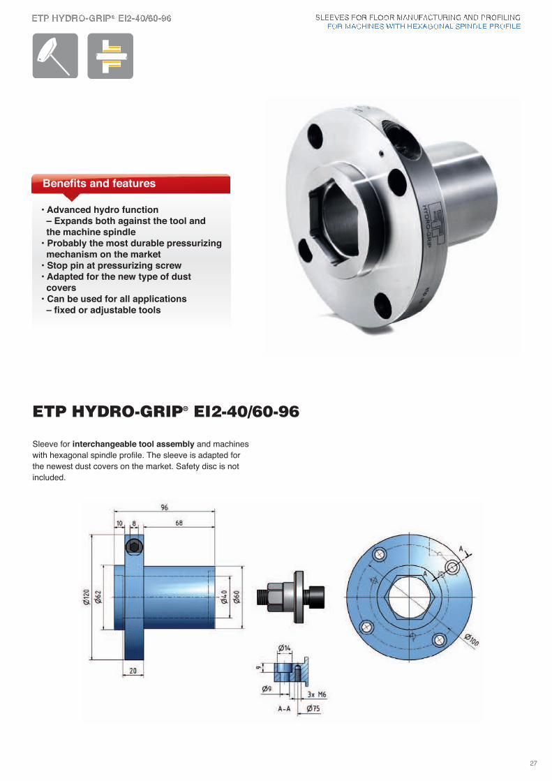
• Advanced hydro function– Expands both against the tool and the machine spindle
• Probably the most durable pressurizingmechanism on the market
• Stop pin at pressurizing screw• Adapted for the new type of dust covers
• Can be used for all applications– fixed or adjustable tools
Benefits and features
Sleeve for interchangeable tool assembly and machines
with hexagonal spindle profile. The sleeve is adapted for
the newest dust covers on the market. Safety disc is not
included.
ETP HYDRO-GRIP® EI2-40/60-96
27
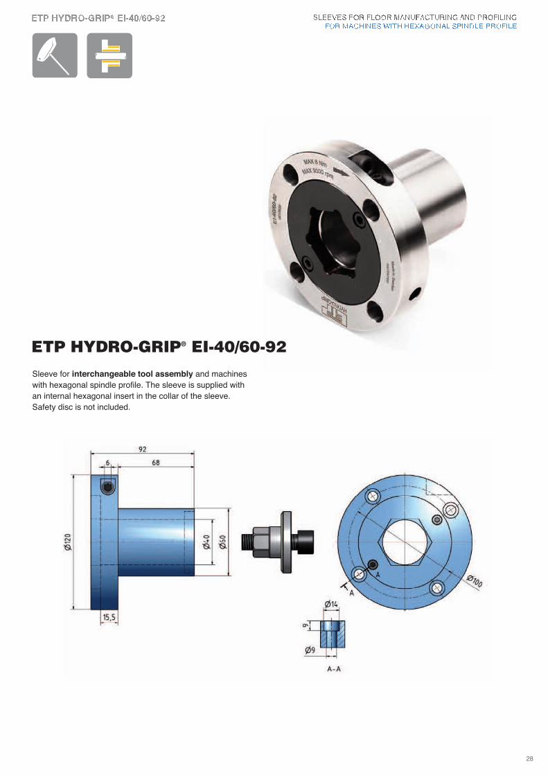
Sleeve for interchangeable tool assembly and machines
with hexagonal spindle profile. The sleeve is supplied with
an internal hexagonal insert in the collar of the sleeve.
Safety disc is not included.
ETP HYDRO-GRIP® EI-40/60-92
28
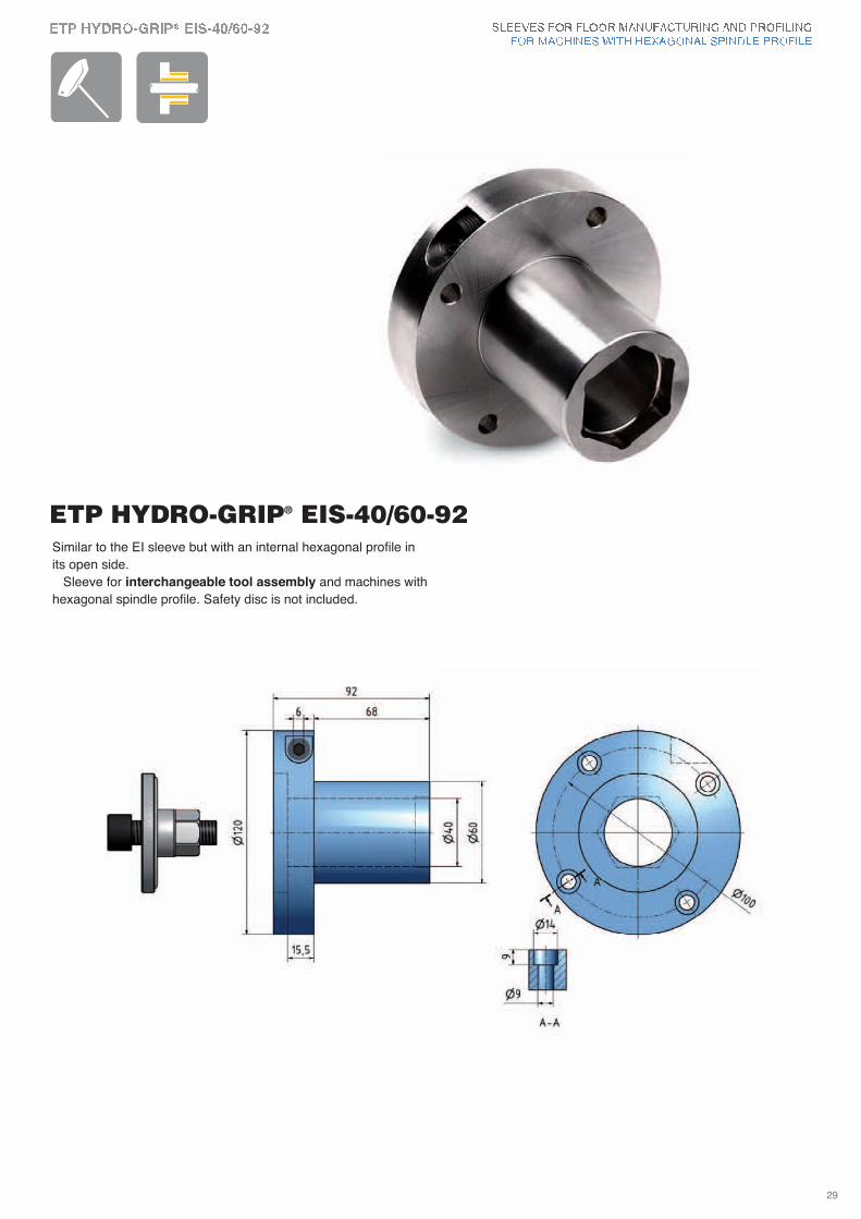
ETP HYDRO-GRIP® EIS-40/60-92Similar to the EI sleeve but with an internal hexagonal profile in
its open side.
Sleeve for interchangeable tool assembly and machines with
hexagonal spindle profile. Safety disc is not included.
29
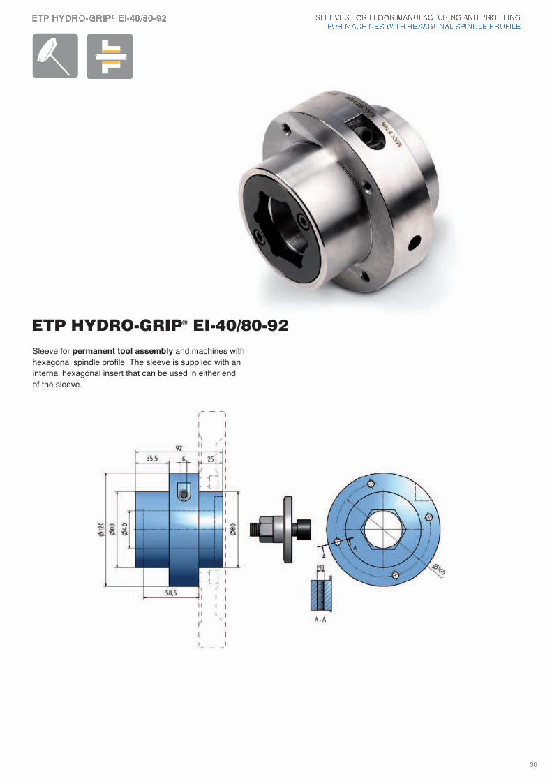
ETP HYDRO-GRIP® EI-40/80-92Sleeve for permanent tool assembly and machines with
hexagonal spindle profile. The sleeve is supplied with an
internal hexagonal insert that can be used in either end
of the sleeve.
30
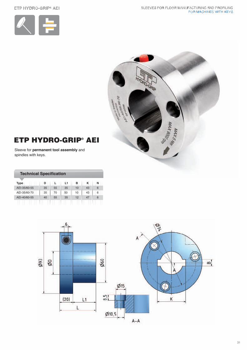
ETP HYDRO-GRIP® AEI
Type D L L1 B K N
Technical Specification
AEI-35/60-55 35 55 35 10 43 6
AEI-35/60-70 35 70 50 10 43 6
AEI-40/60-55 40 55 35 12 47 6
Sleeve for permanent tool assembly and
spindles with keys.
31
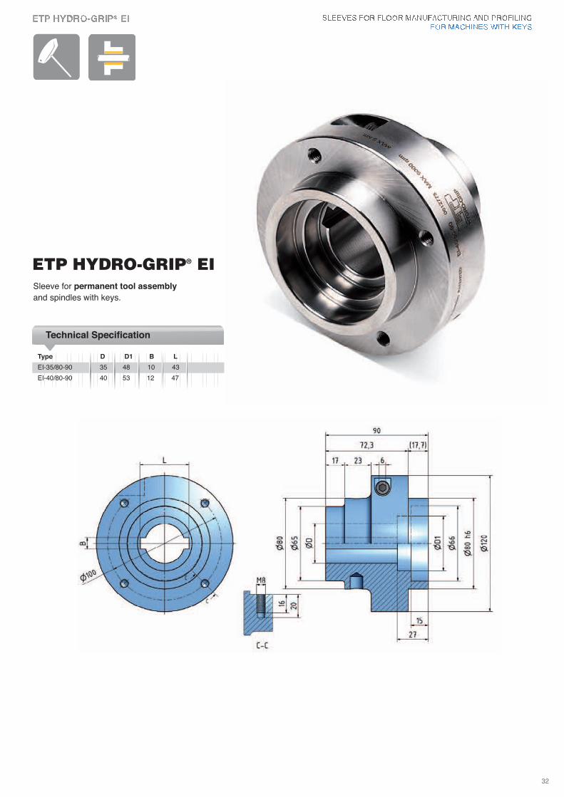
Type D D1 B L
Technical Specification
EI-35/80-90 35 48 10 43
EI-40/80-90 40 53 12 47
Sleeve for permanent tool assembly
and spindles with keys.
ETP HYDRO-GRIP® EI
32
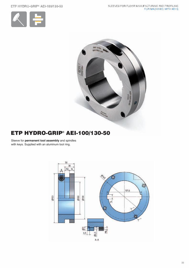
Sleeve for permanent tool assembly and spindles
with keys. Supplied with an aluminum tool ring.
ETP HYDRO-GRIP® AEI-100/130-50
33
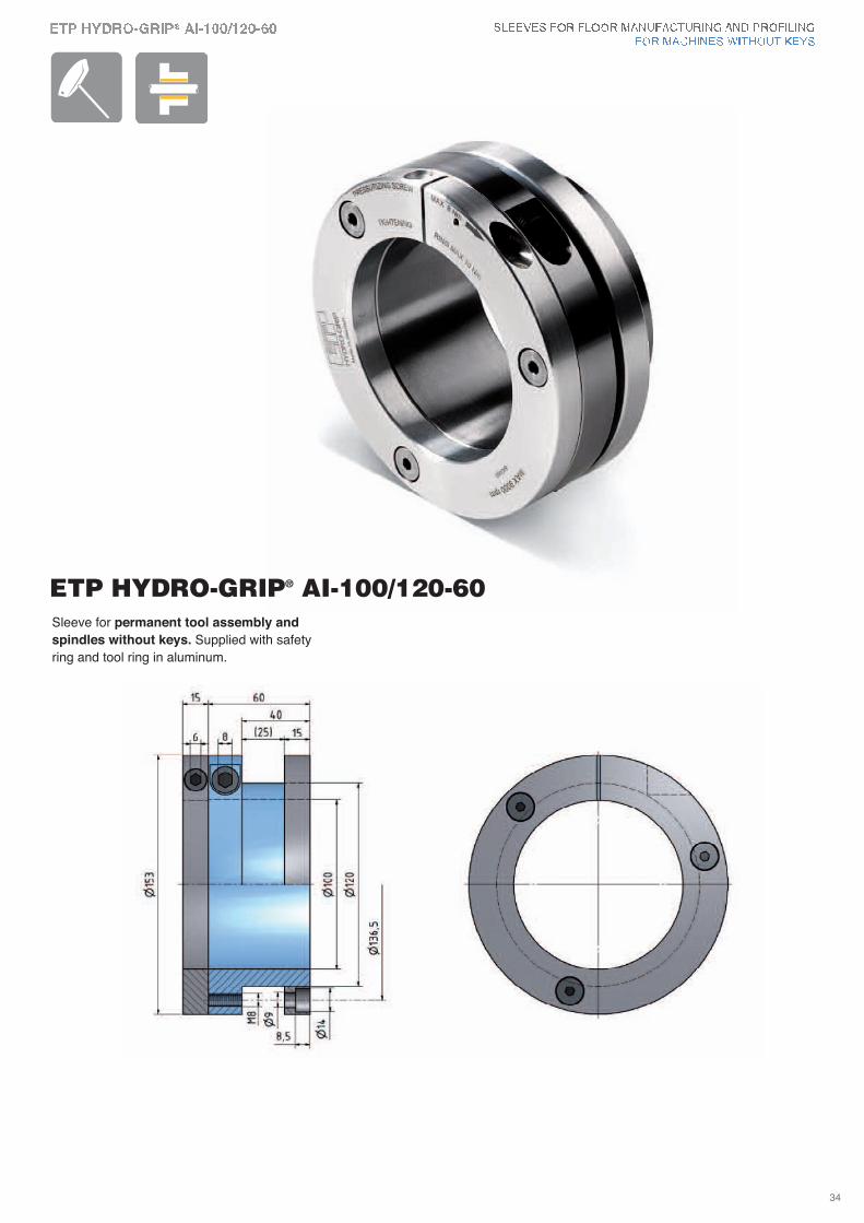
ETP HYDRO-GRIP® AI-100/120-60Sleeve for permanent tool assembly and
spindles without keys. Supplied with safety
ring and tool ring in aluminum.
34
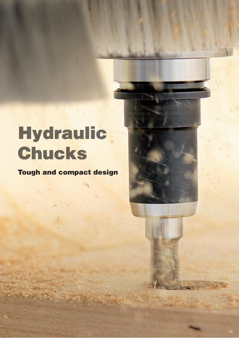
Tough and compact design
35
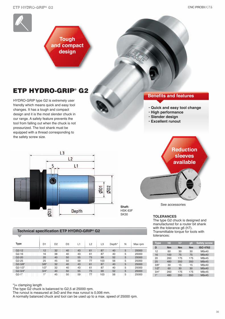
D1 D2 D3 L1 L2 L3 Depth* N Max rpm
G2-12 12 32 40 43 61 87 40 5 25000
G2-16 16 38 40 43 61 87 40 5 25000
G2-20 20 40 50 55 73 99 52 5 25000
G2-25 25 45 50 59 77 103 56 5 25000
G2-3/8" 3/8" 32 40 43 61 87 40 5 25000
G2-1/2" 1/2" 32 40 43 61 87 40 5 25000
G2-3/4" 3/4" 40 50 55 73 99 52 5 25000
G2-1" 1" 45 50 59 77 103 56 5 25000
Type
Technical specification ETP HYDRO-GRIP® G2
HYDRO-GRIP type G2 is extremely user
friendly which means quick and easy tool
changes. It has a tough and compact
design and it is the most slender chuck in
our range. A safety feature prevents the
tool from falling out when the chuck is not
pressurized. The tool shank must be
equipped with a thread corresponding to
the safety screw size.
• Quick and easy tool change• High performance• Slender design• Excellent runout
Tough and compact
design
ETP HYDRO-GRIP® G2
TOLERANCESThe type G2 chuck is designed andmanufactured for a router bit shankwith the tolerance g6 (h7). Transmittable torque for tools withtolerances:
Shaft:
HSK 63F
SK30
*)= clamping lengthThe type G2 chuck is balanced to G2,5 at 25000 rpm.The runout is measured at 3xD and the max runout is 0,006 mm.A normally balanced chuck and tool can be used up to a max. speed of 25000 rpm.
Type h6 h7 g6 Safety screw
D Nm Nm Nm ISO 4762
12 60 30 30 M6x40
16 100 75 75 M6x40
20 260 175 175 M8x45
25 480 350 350 M8x45
3/8" 30 15 15 M6x40
1/2" 60 30 30 M6x40
3/4" 260 175 175 M8x45
1" 480 350 350 M8x45
Benefits and features
36
See accessories
Reduction sleeves
available
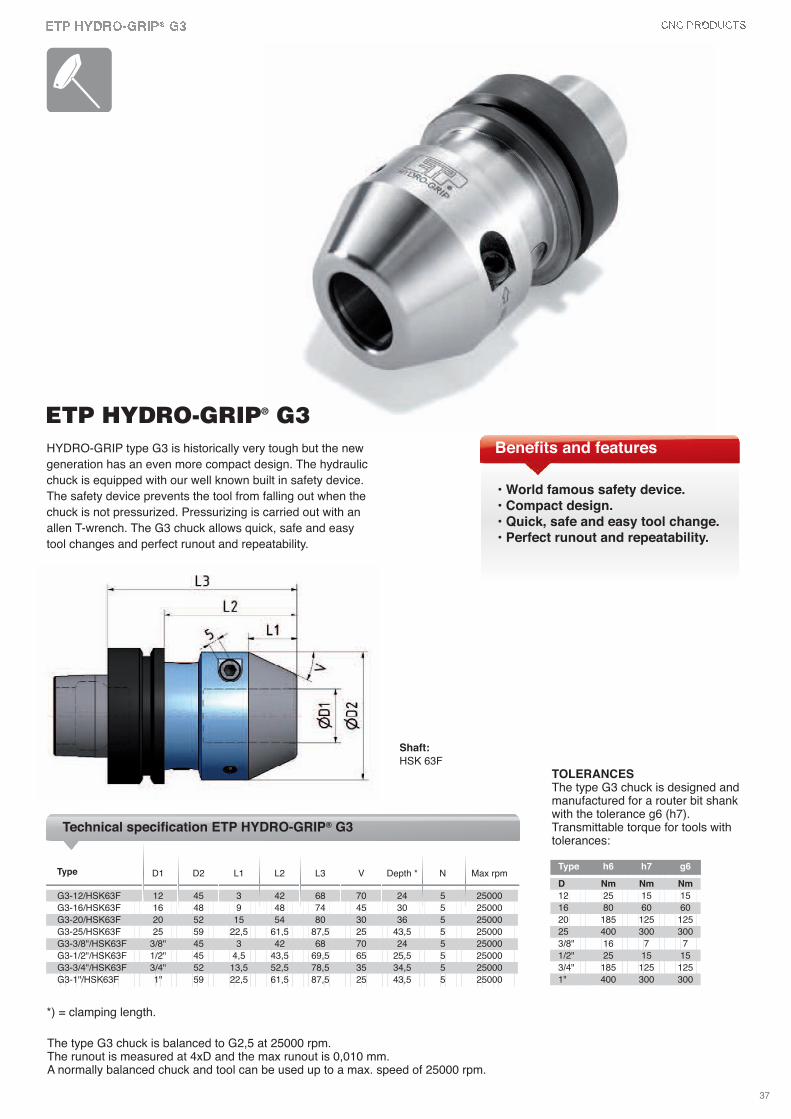
The type G3 chuck is balanced to G2,5 at 25000 rpm.The runout is measured at 4xD and the max runout is 0,010 mm.A normally balanced chuck and tool can be used up to a max. speed of 25000 rpm.
D1 D2 L1 L2 L3 v Depth * N Max rpm
G3-12/HSK63F 12 45 3 42 68 70 24 5 25000
G3-16/HSK63F 16 48 9 48 74 45 30 5 25000
G3-20/HSK63F 20 52 15 54 80 30 36 5 25000
G3-25/HSK63F 25 59 22,5 61,5 87,5 25 43,5 5 25000
G3-3/8"/HSK63F 3/8" 45 3 42 68 70 24 5 25000
G3-1/2"/HSK63F 1/2" 45 4,5 43,5 69,5 65 25,5 5 25000
G3-3/4"/HSK63F 3/4" 52 13,5 52,5 78,5 35 34,5 5 25000
G3-1"/HSK63F 1" 59 22,5 61,5 87,5 25 43,5 5 25000
Type
Technical specification ETP HYDRO-GRIP® G3
HYDRO-GRIP type G3 is historically very tough but the new
generation has an even more compact design. The hydraulic
chuck is equipped with our well known built in safety device.
The safety device prevents the tool from falling out when the
chuck is not pressurized. Pressurizing is carried out with an
allen T-wrench. The G3 chuck allows quick, safe and easy
tool changes and perfect runout and repeatability.
ETP HYDRO-GRIP® G3
TOLERANCESThe type G3 chuck is designed andmanufactured for a router bit shankwith the tolerance g6 (h7).Transmittable torque for tools withtolerances:
Shaft:
HSK 63F
*) = clamping length.
Type h6 h7 g6
D Nm Nm Nm
12 25 15 15
16 80 60 60
20 185 125 125
25 400 300 300
3/8" 16 7 7
1/2" 25 15 15
3/4" 185 125 125
1" 400 300 300
• World famous safety device.• Compact design.• Quick, safe and easy tool change.• Perfect runout and repeatability.
Benefits and features
37
Hydraulic arbors
38
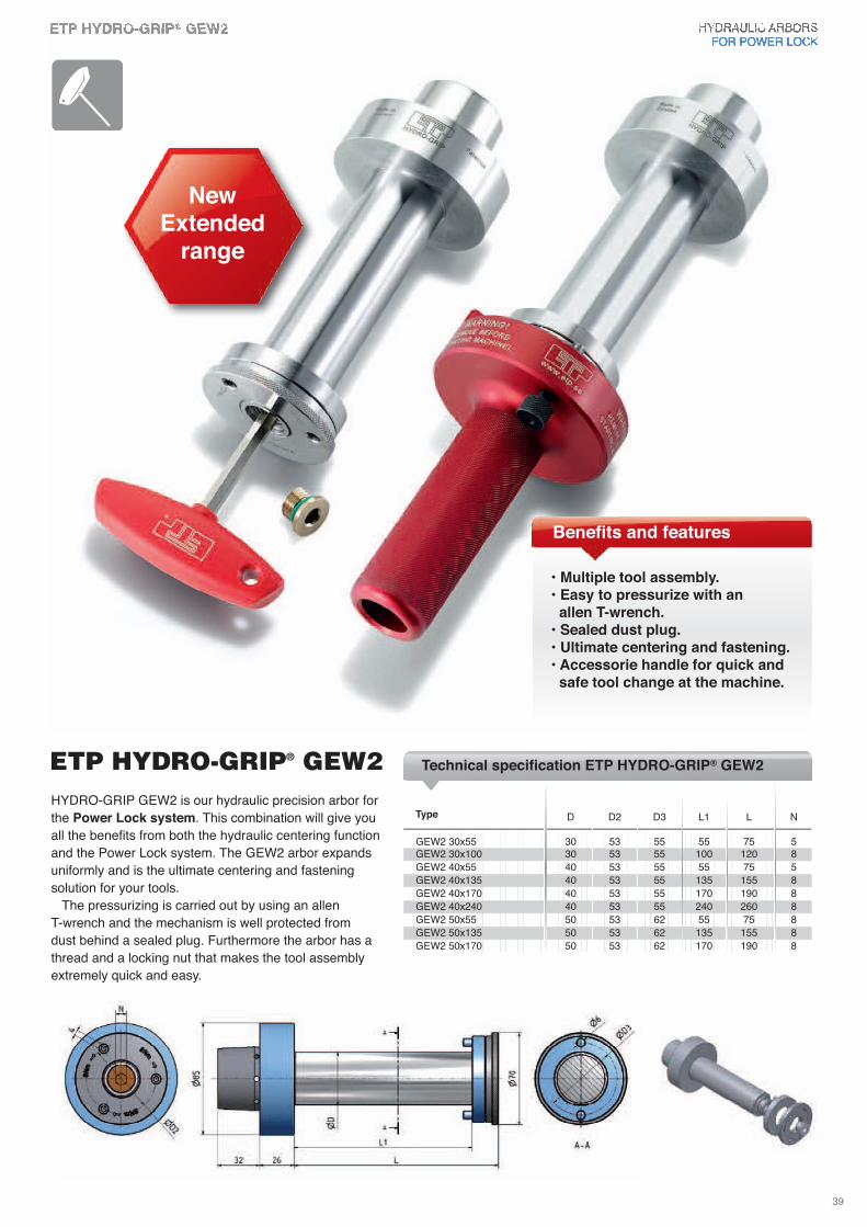
HYDRO-GRIP GEW2 is our hydraulic precision arbor for
the Power Lock system. This combination will give you
all the benefits from both the hydraulic centering function
and the Power Lock system. The GEW2 arbor expands
uniformly and is the ultimate centering and fastening
solution for your tools.
The pressurizing is carried out by using an allen
T-wrench and the mechanism is well protected from
dust behind a sealed plug. Furthermore the arbor has a
thread and a locking nut that makes the tool assembly
extremely quick and easy.
• Multiple tool assembly.• Easy to pressurize with an allen T-wrench.
• Sealed dust plug.• Ultimate centering and fastening.• Accessorie handle for quick and safe tool change at the machine.
NewExtended
range
ETP HYDRO-GRIP® GEW2
Benefits and features
Technical specification ETP HYDRO-GRIP® GEW2
D D2 D3 L1 L N
GEW2 30x55 30 53 55 55 75 5GEW2 30x100 30 53 55 100 120 8
GEW2 40x55 40 53 55 55 75 5
GEW2 40x135 40 53 55 135 155 8
GEW2 40x170 40 53 55 170 190 8
GEW2 40x240 40 53 55 240 260 8
GEW2 50x55 50 53 62 55 75 8
GEW2 50x135 50 53 62 135 155 8
GEW2 50x170 50 53 62 170 190 8
Type
39
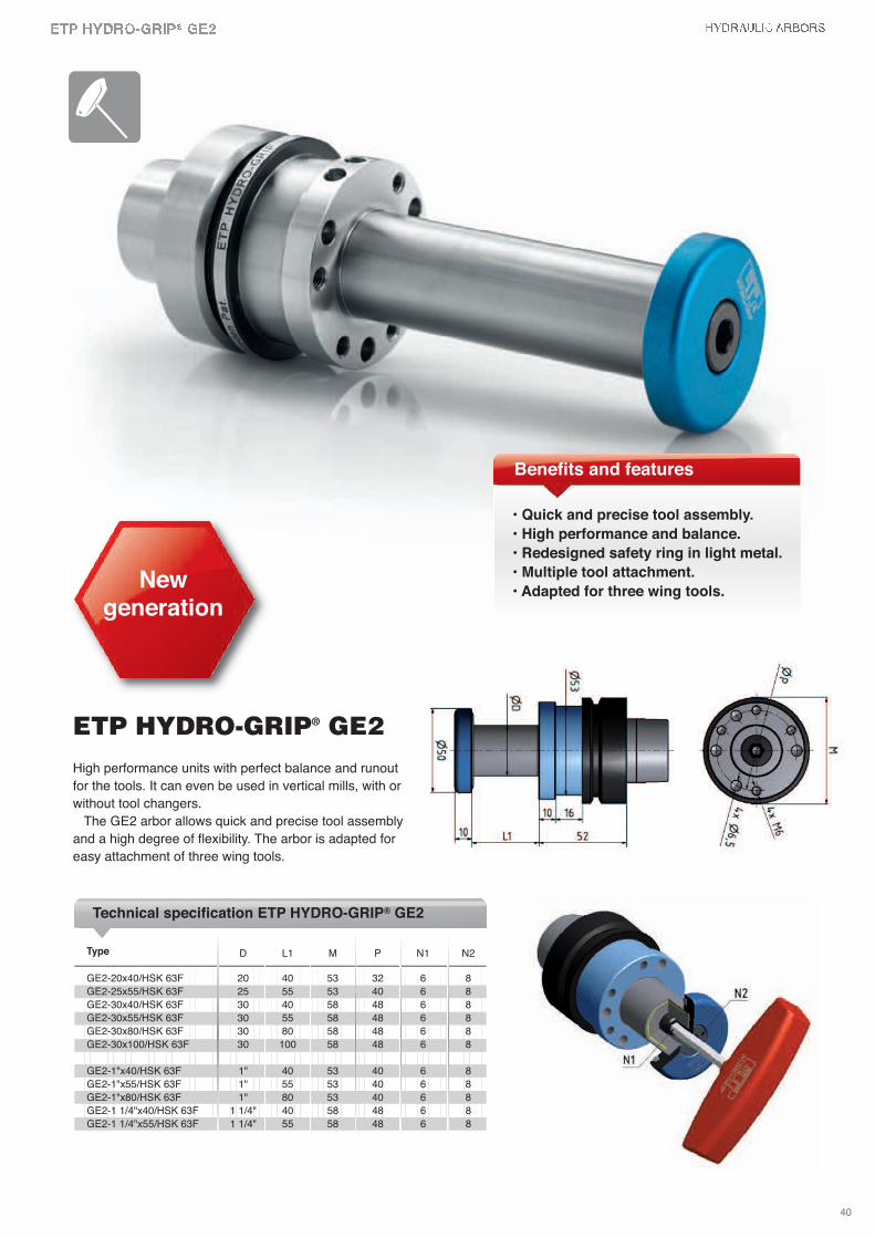
High performance units with perfect balance and runout
for the tools. It can even be used in vertical mills, with or
without tool changers.
The GE2 arbor allows quick and precise tool assembly
and a high degree of flexibility. The arbor is adapted for
easy attachment of three wing tools.
• Quick and precise tool assembly.
• High performance and balance.
• Redesigned safety ring in light metal.
• Multiple tool attachment.
• Adapted for three wing tools.New
generation
ETP HYDRO-GRIP® GE2
Benefits and features
Technical specification ETP HYDRO-GRIP® GE2
D L1 M P N1 N2
GE2-20x40/HSK 63F 20 40 53 32 6 8
GE2-25x55/HSK 63F 25 55 53 40 6 8
GE2-30x40/HSK 63F 30 40 58 48 6 8
GE2-30x55/HSK 63F 30 55 58 48 6 8
GE2-30x80/HSK 63F 30 80 58 48 6 8
GE2-30x100/HSK 63F 30 100 58 48 6 8
GE2-1"x40/HSK 63F 1" 40 53 40 6 8
GE2-1"x55/HSK 63F 1" 55 53 40 6 8
GE2-1"x80/HSK 63F 1" 80 53 40 6 8
GE2-1 1/4"x40/HSK 63F 1 1/4" 40 58 48 6 8
GE2-1 1/4"x55/HSK 63F 1 1/4" 55 58 48 6 8
Type
40
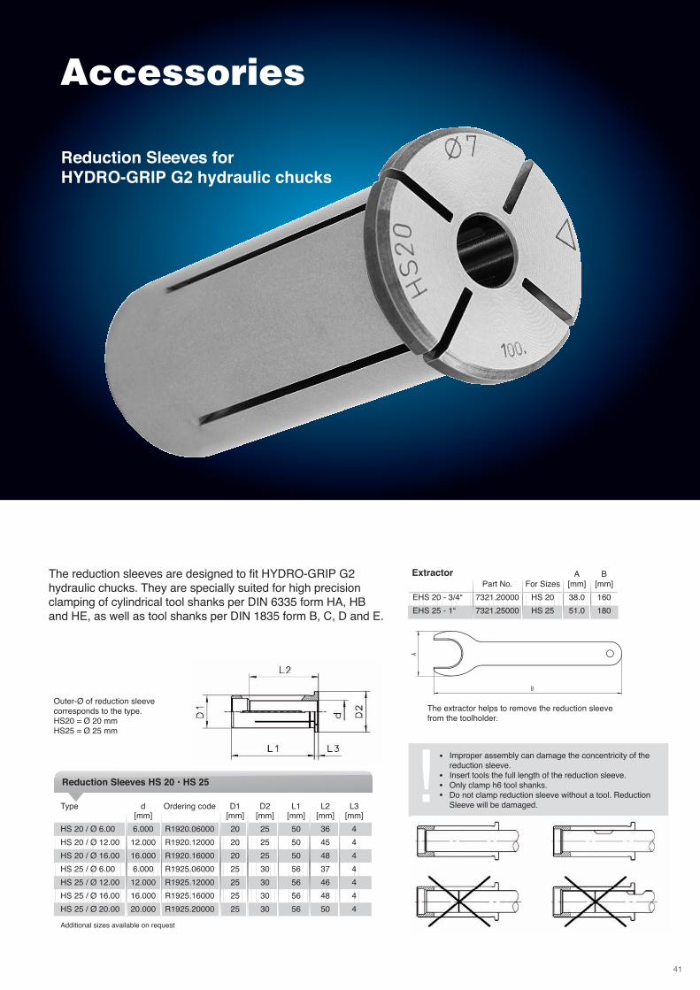
Accessories
The reduction sleeves are designed to fit HYDRO-GRIP G2 hydraulic chucks. They are specially suited for high precisionclamping of cylindrical tool shanks per DIN 6335 form HA, HBand HE, as well as tool shanks per DIN 1835 form B, C, D and E.
Improper assembly can damage the concentricity of thereduction sleeve.Insert tools the full length of the reduction sleeve.Only clamp h6 tool shanks.Do not clamp reduction sleeve without a tool. ReductionSleeve will be damaged.
•
•••!Reduction Sleeves HS 20 • HS 25
Extractor
The extractor helps to remove the reduction sleevefrom the toolholder.
A BPart No. For Sizes [mm] [mm]
EHS 20 - 3/4“ 7321.20000 HS 20 38.0 160
EHS 25 - 1“ 7321.25000 HS 25 51.0 180
Reduction Sleeves forHYDRO-GRIP G2 hydraulic chucks
Outer-Ø of reduction sleeve corresponds to the type.HS20 = Ø 20 mmHS25 = Ø 25 mm
Type d Ordering code D1 D2 L1 L2 L3[mm] [mm] [mm] [mm] [mm] [mm]
HS 20 / Ø 6.00 6.000 R1920.06000 20 25 50 36 4
HS 20 / Ø 12.00 12.000 R1920.12000 20 25 50 45 4
HS 20 / Ø 16.00 16.000 R1920.16000 20 25 50 48 4
HS 25 / Ø 6.00 6.000 R1925.06000 25 30 56 37 4
HS 25 / Ø 12.00 12.000 R1925.12000 25 30 56 46 4
HS 25 / Ø 16.00 16.000 R1925.16000 25 30 56 48 4
HS 25 / Ø 20.00 20.000 R1925.20000 25 30 56 50 4
Additional sizes available on request
41
Type D D1 t
D-60/90-5 60 90 5
D-60/90-10 60 90 10
D-60/90-20 60 90 20
DH-60/90-3 60 90 3
DH-60/90-5 60 90 5
DH-60/90-10 60 90 10
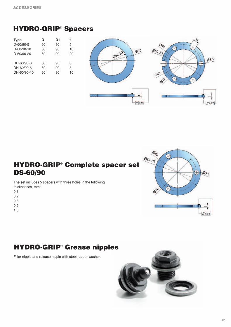
HYDRO-GRIP® Spacers
The set includes 5 spacers with three holes in the following
thicknesses, mm:
0.1
0.2
0.3
0.5
1.0
HYDRO-GRIP® Complete spacer setDS-60/90
Filler nipple and release nipple with steel rubber washer.
HYDRO-GRIP® Grease nipples
42
43
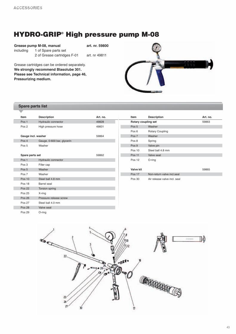
Grease pump M-08, manual art. nr. 59800
including 1 of Spare parts set
2 of Grease cartridges F-01 art. nr 49811
Grease cartridges can be ordered separately.
We strongly recommend Blasolube 301.
Please see Technical information, page 46,
Pressurizing medium.
Item Description Art. no.
Pos 1 Hydraulic connector 49828
Pos 2 High pressure hose 49831
Gauge incl. washer 59864
Pos 4 Gauge, 0-600 bar, glycerin
Pos 5 Washer
Spare parts set 59862
Pos 1 Hydraulic connector
Pos 3 Filler cap
Pos 5 Washer
Pos 7 Washer
Pos 10 Steel ball 4.8 mm
Pos 18 Barrel seal
Pos 22 Torsion spring
Pos 25 x-ring
Pos 26 Pressure release screw
Pos 27 Steel ball 4.0 mm
Pos 28 valve seat
Pos 29 O-ring
Item Description Art. no.
Rotary coupling set 59863
Pos 5 Washer
Pos 6 Rotary Coupling
Pos 7 Washer
Pos 8 Spring
Pos 9 valve pin
Pos 10 Steel ball 4.8 mm
Pos 11 valve seat
Pos 12 O-ring
Valve kit 59865
Pos 17 Non-return valve incl.seal
Pos 30 Air release valve incl. seal
HYDRO-GRIP® High pressure pump M-08
Spare parts list
Quicker tool changesBy pre-assembling HYDRO-GRIP and the tool in the toolroomyou minimize the adjustment time at the processing machine.
Advice for tool assemblyIt is vital that HYDRO-GRIP is never pressurized without beingassembled with a tool on a machine spindle.
NB! Both the tool and the machine spindle must cover thelength of the sleeve. To achieve optimal stability you must ensure an even contact surface throughout the entire sleeve.More detailed instructions for HYDRO-GRIP are included inthe assembly instructions which are included with every product.
TemperatureThanks to the small volume of pressurizing medium used,HYDRO-GRIP is only minimally sensitive to temperature changes. Only if the temperature varies by as much as +/- 30°C do you need to adjust the pressure of the sleeve.
RepeatabilityThe incredible repeatability that HYDRO-GRIP gives you, within 0.002 mm, allows you to achieve the same precisioneven on your production machine as you achieve on your grinding machine. The same repeatability is attained whenusing a G2, G3 or GE type hydraulic chuck/arbor.
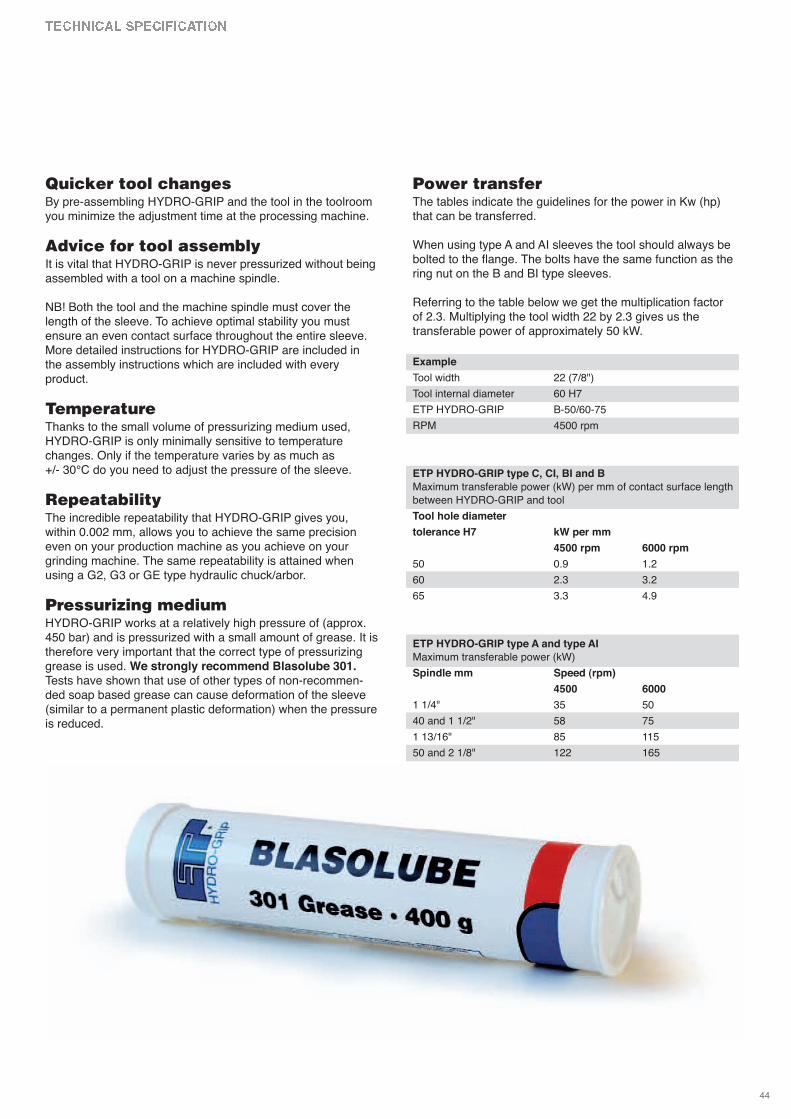
Pressurizing mediumHYDRO-GRIP works at a relatively high pressure of (approx.450 bar) and is pressurized with a small amount of grease. It istherefore very important that the correct type of pressurizinggrease is used. We strongly recommend Blasolube 301.Tests have shown that use of other types of non-recommen-ded soap based grease can cause deformation of the sleeve(similar to a permanent plastic deformation) when the pressureis reduced.
Power transferThe tables indicate the guidelines for the power in Kw (hp)that can be transferred.
When using type A and AI sleeves the tool should always bebolted to the flange. The bolts have the same function as thering nut on the B and BI type sleeves.
Referring to the table below we get the multiplication factor of 2.3. Multiplying the tool width 22 by 2.3 gives us the transferable power of approximately 50 kW.
Example
Tool width 22 (7/8")
Tool internal diameter 60 H7
ETP HYDRO-GRIP B-50/60-75
RPM 4500 rpm
ETP HYDRO-GRIP type C, CI, BI and B
Maximum transferable power (kW) per mm of contact surface length
between HYDRO-GRIP and tool
Tool hole diameter
tolerance H7 kW per mm
4500 rpm 6000 rpm
50 0.9 1.2
60 2.3 3.2
65 3.3 4.9
ETP HYDRO-GRIP type A and type AI
Maximum transferable power (kW)
Spindle mm Speed (rpm)
4500 6000
1 1/4" 35 50
40 and 1 1/2" 58 75
1 13/16" 85 115
50 and 2 1/8" 122 165
44
Use of screws in the ring nut(Type B, BI and BL). The knurled ring nut only needs to belightly tightened so the tools are in contact with each other.Tightening the three screws in the ring nut ensures that thetools are safely and accurately fixed into position. This allowsyou to maintain the accuracy achieved on the grinding ma-chine when you move the sleeve and tool assembly to thespindle on your production machine.
TolerancesETP HYDRO-GRIP is intended for machine spindle toleranceg6 and tool tolerance H7. (See tables to right).
Permanent assemblyA tool with a hole tolerance of H7 gives a light press fit on thesleeves meant for permanent assembly, type A and AI. Whenpressurized the sleeve expands against the spindle, thus elimi-nating any play between the sleeve and spindle.
Interchangeable assemblyA tool with a hole tolerance of H7 gives a an easy slip fit onsleeves meant for interchangeable tool assembly, type CIR, CI,C, BI and B. When pressurized the sleeve expands against thespindle, thus eliminating any play between the tool andspindle.
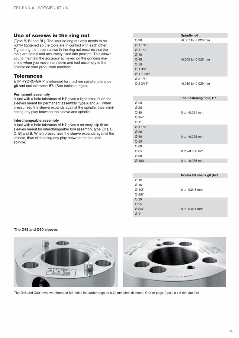
The Ø45 and Ø50 sleeves
Spindle, g6
Ø 30 -0.007 to -0.020 mm
Ø 1 1/4"
Ø 1 1/2"
Ø 40
Ø 45 -0.009 to -0.025 mm
Ø 50
Ø 1 3/4"
Ø 1 13/16"
Ø 2 1/8"
Ø 2 3/16" -0.010 to -0.029 mm
Tool fastening hole, H7
Ø 20
Ø 25
Ø 30 0 to +0.021 mm
Ø 3/4"
Ø 1"
Ø 1 1/4"
Ø 38
Ø 40 0 to +0.025 mm
Ø 50
Ø 60
Ø 65 0 to +0.030 mm
Ø 80
Ø 100 0 to +0.035 mm
Router bit shank g6 (h7)
Ø 12
Ø 16
Ø 1/2" 0 to -0.018 mm
Ø 5/8"
Ø 20
Ø 25
Ø 3/4" 0 to -0.021 mm
Ø 1"
45
The Ø45 and Ø50 have two, threaded M8-holes for carrier pegs on a 70 mm pitch diameter. Carrier pegs, 2 pcs, 8 x 5 mm are incl.