wjert, 2017, vol. 3, issue 2, 185 -197 original article issn 2454...
TRANSCRIPT

Susanchi et al. World Journal of Engineering Research and Technology
www.wjert.org
185
“DESIGN AND SIMULATION OF DOUBLE SIDE BAND SUPPRESSED
CARRIER MODEL USING MATLAB SIMULINK TOOL AND EFFECT
OF NOISE ON SIMULATION RESULTS USING MATLAB CODING”
*1Susanchi Raut,
1Shivani Umredkar and
2Prof. Kanchan Wagh
1B.E Final year (8th sem), Electronics and Telecommunication St. Vincent Pallotti College of
Engg & Tech., Nagpur.
2Assistant Professor Dept. of Electronics and Telecommunication St. Vincent Pallotti College
of Engg & Tech., Nagpur.
Article Received on 09/02/2017 Article Revised on 02/03/2017 Article Accepted on 23/03/2017
ABSTRACT
For long distance communication efficient and effective transmission
plays a vital role for which modulation techniques are required. In
conventional AM transmission, the sinusoidal component at the carrier
frequency which does not contain information and both the side bands
(upper sideband and lower sideband) are present i.e., DSB-AM.
Therefore, the presence of carrier results in 2/3rd
power loss. In order to
overcome this problem the carrier signal is suppressed, i.e., removed producing double-side
band suppressed carrier (DSBSC). In DSBSC real information is preserved and power
wastage is prevented. In this paper more emphasis is on the design and simulation of DSBSC
modulation and detection using the Simulink tool of MATLAB. This paper also talks about
the effect of noise on simulation results.
KEYWORDS: Double side band suppressed carrier, Spectrum analyzer, modulation index,
Additive wave guassian noise (awgn).
INTRODUCTION
Communication refers to sending and receiving and processing of information by electronic
means. It is started with wired telegraphy in 18th
century developing with telephony, some
decades later and radio at the beginning of this century. Radio communication made possible
wjert, 2017, Vol. 3, Issue 2, 185 -197
World Journal of Engineering Research and Technology
WJERT
www.wjert.org
ISSN 2454-695X Original Article
SJIF Impact Factor: 4.326
*Corresponding Author
Susanchi Raut
B.E final year (8th sem),
Electronics and
Telecommunication St.
Vincent Pallotti college of
Engg & Tech., Nagpur.

Susanchi et al. World Journal of Engineering Research and Technology
www.wjert.org
186
by invention of triode tubes, thin transistor IC’s and semiconductor devices. News of satellite
and fiber optics has made communication more wide spread.
Forms of communication:
Telegraphy
Telephony
Broadcasting
Mobile communication
Radio communication
Computer communication
Radar
Satellite communication
Radio telemetry
Figure 1: Block diagram of communication system.
What is modulation?
It is defined as the process by which some parameter of a high frequency signal is varied in
accordance with the signal to be transmitted.
The parameter here may be frequency, phase, amplitude, etc. OR it can be defined as process
of superimposing high frequency carrier signal with the broadcast /modulating signal.
In modulation process baseband signal modifies the carrier signal.

Susanchi et al. World Journal of Engineering Research and Technology
www.wjert.org
187
Need of modulation
Modulating signals are incompatible for direct transmission over the medium, and we have to
use modulation techniques.
Advantages
Reduces the height of an antenna.
Avoids mixing of signals.
Increase the range of communication.
Allows multiplexing of signal.
Improves quality of reception.
Amplitude modulation
When the amplitude of the carrier signal is varied in accordance with the amplitude of
modulating signal is called amplitude modulation keeping frequency and phase constant.
THEORY
What is DSBSC?
DSB-SC is a double sideband suppressed carrier modulation. When amplitude modulation is
carried out; the modulating signal spectrum is shifted to the carrier frequency band. DSB-SC
is named because the modulating signal extends symmetrically on both sides of the carrier
wave. DBB-SC is a transmission in which frequencies produced by amplitude modulation
(AM) are symmetrically spaced above and below the carrier frequency and the carrier level is
reduced to the lowest practical level, ideally being completely suppressed. In the DSB-SC
modulation, unlike in AM, the wave carrier is not transmitted; this much of power is
distributed between the sidebands, which imply an increase of the cover in DSB-SC,
compared to AM, for the same power used.
The real information is conveyed using two side-bands. To make AM system more efficient,
we will simply suppress the carrier which does not contain any information.
When the carrier signal is removed then the remaining signal contain only two side bands
such signal called double sideband suppressed carrier (DSB-SC) signal.

Susanchi et al. World Journal of Engineering Research and Technology
www.wjert.org
188
Modulation
The simplest modulation method to implement is DSB, in which the translated spectrum of
the message signal is transmitted without further modification. From the real signal frequency
translation property of the Fourier transform, the spectrum of the message signal x(t) is
translated to the frequency fc by multiplying x(t) with a carrier waveform Accos(2πfct).The
modulated waveform xc(t) is xc(t) = Acx(t)cos(2πfct) whose spectrum is:
Xc(f)=(Ac/2)*[X(f+fc)+X(f-fc)]
Vmcos(ωmt)×Vccos(ωct)=(VmVc/2)[(cos(ωm+ωc)t)+ (cos(ωm-ωc)t)]
[1]
Demodulation
Coherent (Synchronous) Demodulator (Detector): sThe receiver knows exactly the phase and
frequency of the received signal. Demodulation is done by multiplying the DSB-SC signal
with the carrier signal just like the modulation process. This resultant signal is then passed
through a low pass filter to produce a scaled version of the original message signal. DSB-SC
can be demodulated by a simple envelope detector, like AM, if the modulation index is less
than unity. Full depth modulation requires carrier re-insertion.
(VmVc/2)[(cos(ωm+ωc)t)+(cos(ωm-ωc)t)]×Vc’cos(ωct)=
(VcVc’Vm)cos(ωmt)+1/2VcVc’Vm[cos((ωm+2ωc)t)+ cos((ωm-2ωc)t)]
The equation above shows that by multiplying the modulated signal by the carrier signal, the
result is a scaled version of the original message signal plus a second term. Since, this second
term is much higher in frequency than the original message. Once this signal passes through a
low pass filter, the higher frequency component is removed, leaving just the original message.
Modulating signal Carrier signal Modulated signal
Susanchi et al. World Journal of Engineering Research and Technology
www.wjert.org
189
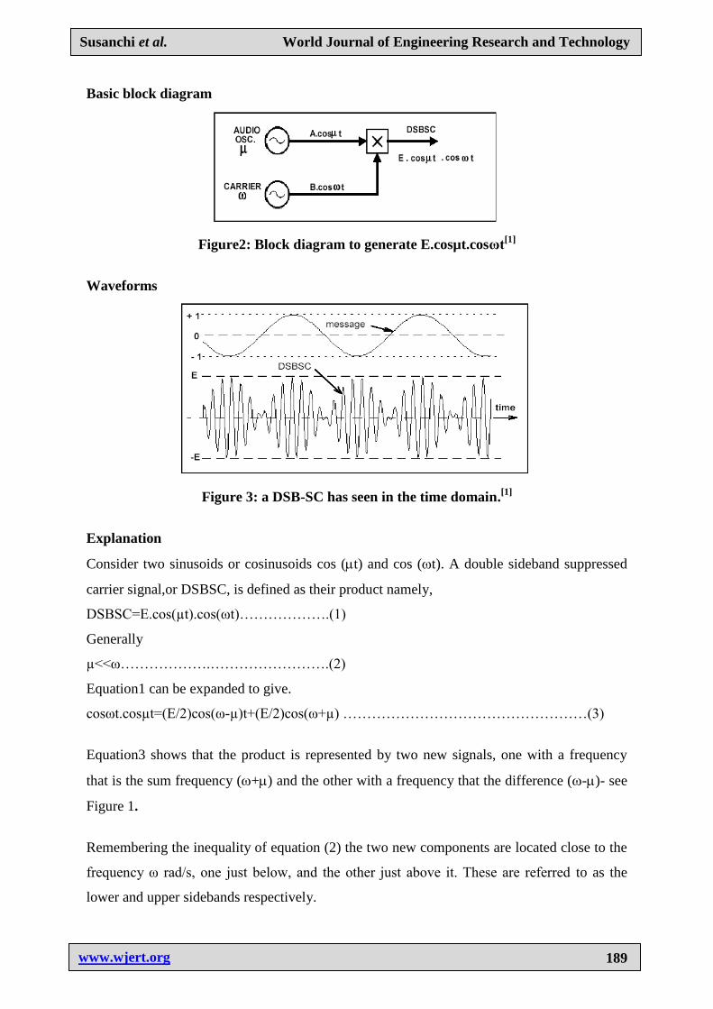
Basic block diagram
Figure2: Block diagram to generate E.cosµt.cosωt[1]
Waveforms
Figure 3: a DSB-SC has seen in the time domain.[1]
Explanation
Consider two sinusoids or cosinusoids cos (t) and cos (t). A double sideband suppressed
carrier signal,or DSBSC, is defined as their product namely,
DSBSC=E.cos(µt).cos(ωt)……………….(1)
Generally
µ<<ω……………….…………………….(2)
Equation1 can be expanded to give.
cosωt.cosµt=(E/2)cos(ω-µ)t+(E/2)cos(ω+µ) ……………………………………………(3)
Equation3 shows that the product is represented by two new signals, one with a frequency
that is the sum frequency (+) and the other with a frequency that the difference (-)- see
Figure 1.
Remembering the inequality of equation (2) the two new components are located close to the
frequency ω rad/s, one just below, and the other just above it. These are referred to as the
lower and upper sidebands respectively.

Susanchi et al. World Journal of Engineering Research and Technology
www.wjert.org
190
Figure 4: Spectral components.[1]
These two components were derived from a carrier term with a frequency of rad/s, and a
message with a frequency of rad/s. Due to the absence of the carrier component in the
product signal, this product signal is described as a Double Sideband Suppressed Carrier
(DSBSC) signal. The term carrier comes from the context of double sideband amplitude
modulation (commonly abbreviated to just AM). AM is introduced in a later experiment
(although, historically, AM preceded DSBSC). The time domain appearance of a DSBSC
(equation. 1) is generally as shown in Figure 2. Although the message and the carrier are
periodic waveforms (sinusoids), the DSBSC itself need not necessarily be periodic.
Figure 5: Typical display of a DSBSC with the message from which it was delivered as
seen on an oscilloscope.[1]
Spectrum analysis
DSB-SC is basically an amplitude modulation wave without the carrier, therefore reducing
power waste giving it a 50% efficiency. this an increase compare to normal AM channel
(DBS) maximum efficiency of 33.333% since 2/3 of the power is in the carrier which carries
no intelligece, and each sideband carries the same information.

Susanchi et al. World Journal of Engineering Research and Technology
www.wjert.org
191
Simulink model of DSB-SC
There are few steps that are to be followed
Step 1: Open the matlab window.
Step 2: Open Simulink library.
Susanchi et al. World Journal of Engineering Research and Technology
www.wjert.org
192
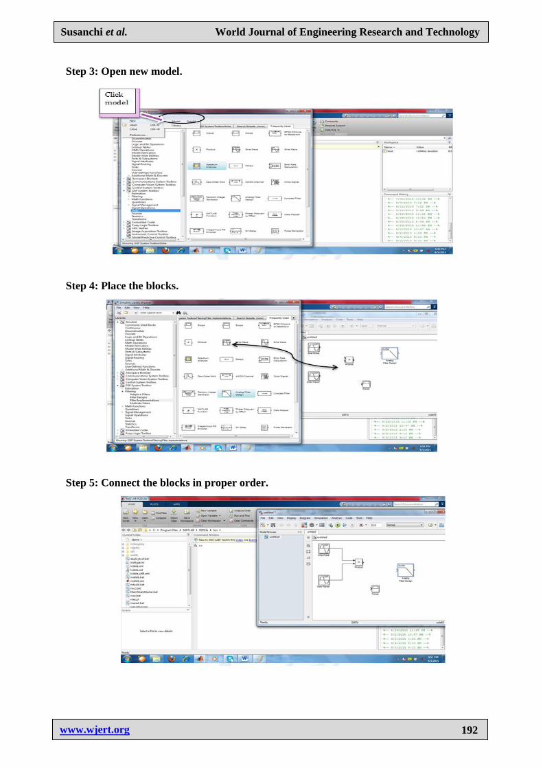
Step 3: Open new model.
Step 4: Place the blocks.
Step 5: Connect the blocks in proper order.

Susanchi et al. World Journal of Engineering Research and Technology
www.wjert.org
193
Step 6: Required Simulink model.
Step 7: Output
Step 8: Spectrum analysis
Susanchi et al. World Journal of Engineering Research and Technology
www.wjert.org
194
MATLAB Coding and effect of noise on
DSB-SC signal.
clc;
clear all;
t = 0:0.001:1;
Message_Signal_Amplitude = input('Enter the Amplitude of Message Signal = ');
Carrier_Signal_Amplitude = input('Enter the Amplitude of Carrier Signal = ');
Message_Signal_Frequency = input('Enter the Message Frequency = ');
Carrier_Signal_Frequency = input('Enter the Carrier Frequency = ');
m = Message_Signal_Amplitude/Carrier_Signal_Amplitude;
% Representation of the Message Signal
sm = Message_Signal_Amplitude.*sin(2*pi*Message_Signal_Frequency*t);
subplot(7,1,1);
plot(t,sm,'b');
xlabel('Time');
ylabel('Amplitude');
title('Message Signal');
legend('Message Signal');
grid on;
% Representation of the Carrier Signal
sc = Carrier_Signal_Amplitude.*sin(2*pi*Carrier_Signal_Frequency*t);
subplot(7,1,2);
plot(t,sc,'black');
xlabel('Time');
ylabel('Amplitude');
title('Carrier Signal');
legend('Carrier Signal');
grid on;
% Representation of the AM Signal
Amplitude_Modulated_Signal =
(Message_Signal_Amplitude+m*Message_Signal_Amplitude.*sin(2*pi*Message_Signal_Fr
equency*t)).*sin(2*pi*Carrier_Signal_Frequency*t);
subplot(7,1,3);
plot(t,Amplitude_Modulated_Signal,'red');

Susanchi et al. World Journal of Engineering Research and Technology
www.wjert.org
195
xlabel('Time');
ylabel('Amplitude');
title('Amplitude Modulated Wave');
legend('AM Signal');
grid on;
%%%NOISE
% Representation of the Message Signal
sm = Message_Signal_Amplitude.*sin(2*pi*Message_Signal_Frequency*t);
y=awgn(sm,1);
subplot(7,1,4);
plot(t,y,'b');
xlabel('Time');
ylabel('Amplitude');
title('Message Signal');
legend('Message Signal');
grid on;
% Representation of the Carrier Signal
sc = Carrier_Signal_Amplitude.*sin(2*pi*Carrier_Signal_Frequency*t);
subplot(7,1,5);
plot(t,sc,'green');
xlabel('Time');
ylabel('Amplitude');
title('Carrier Signal');
legend('Carrier Signal');
grid on;
% Representation of the AM Signal
Amplitude_Modulated_Signal =
(Message_Signal_Amplitude+m.*y).*sin(2*pi*Carrier_Signal_Amplitude);
y=awgn(Amplitude_Modulated_Signal,1);
subplot(7,1,6);
plot(t,y,'red');
xlabel('Time');
ylabel('Amplitude');
title('Amplitude Modulated Wave');

Susanchi et al. World Journal of Engineering Research and Technology
www.wjert.org
196
legend('AM Signal');
grid on;
Output
Enter the Amplitude of Message Signal = 15
Enter the Amplitude of Carrier Signal = 20
Enter the Message Frequency = 30
Enter the Carrier Frequency = 50
Waveforms
CONCLUSION
After doing this model it is clear that due to suppression of carrier signal, power is not
wasting. The System becomes more efficient.Efficiency becomes 100%.
But there are some disadvantages
Both the side-bands contain the same information. Hence passing of two sidebands leads to
power wastage. Hence, after improving this system single side-band suppression carrier has
been obtained.
Future scope
The model works in theory, but not in practice due to the fact that second sine wave in the
model used as a mixer cannot have the same specifications as the carrier in real application.
The original carrier and the second sine wave will run relative to one another in real-time. It
is only a phase locked loop that can keep track of the instantaneous differences between

Susanchi et al. World Journal of Engineering Research and Technology
www.wjert.org
197
frequency and phase of two signals. Further work on this model is the designed model of the
SSB-SC and VSB.
REFERENCES
1. A1-03_DSBSC generation -1.pdf by Emona Instrument Pty Ltd.
2. Kennedy and Davis: Electronic Communication Systems, Tata McGraw Hills Publication
(Fourth Edition).
3. www.mathwork.com
4. Video lecture on matlab simulation. (http://video.mit.edu/watch/introduction-to-matlab-
programming-lecture-1-using-matlab-for-the-first-time-14057/)
Susanchi Raut
8983699163
Address: Plot no.25/A,Mitra Nagar,
Behind Gajanan Temple, Manewada Road,Nagpur.
Bachelor of Engineering (BE 4th
year)
Department of Electronics and Telecommunication
St. Vincent Pallotti college of Engineering and
Technology, Nagpur, Maharashtra, India.
Shivani Umredkar
7350068260
Address: Plot no.42, Sainagar1, Hudkeshwar Road,
Nagpur.
Bachelor of Engineering(BE 4th
year)
Department of Electronics and Telecommunication.
St.Vincent Pallotti college of Engineering and Technology,
Nagpur, Maharashtra, India.
Prof. Kanchan Wagh
7722046116
Assistant Professor
Department of Electronics and Telecommunication.
St. Vincent Pallotti college of Engineering and
Technology, Nagpur, Maharashtra, India.