wireless tutorial part 2 the ieee’s wireless ethernet keeps going and growing 4g tutorial: vive la...
TRANSCRIPT

Wireless TutorialPart 2
The IEEE’s Wireless Ethernet Keeps Going and
Growing
4G Tutorial: Vive la Différence?
Brough TurnerDialogic
Fanny MlinarskyoctoScope

Agenda10:30 – 12:00 noon Our G-enealogy – History and Evolution of
Mobile Radio Lunch
1:00 – 2:00 The IEEE’s Wireless Ethernet Keeps Going and Growing
2:00 – 2:45 4G Tutorial: Vive la Différence?Break
3:00 – 3:45 Mobile Broadband - New Applications and New Business ModelsBreak
4:00 – 4:45 Tutorial: White Spaces and Beyond

Wire
less
cap
acity
/ t
hrou
ghpu
t
1970 1980 1990 2000 2010
First cell phones
AMPS
GSMCDMA
Wi-FiWiMAX
LTE
Increasing throughput a
nd capacity
OFDM →OFDMA
UMTS/HSxPA2G
3G
4G
IEEE 802
MIMO

History of IEEE 802.11• 1989: FCC authorizes ISM bands
(Industrial, Scientific and Medical)
– 900 MHz, 2.4 GHz, 5 GHz
• 1990: IEEE begins work on 802.11
• 1994: 2.4 GHz products begin shipping
• 1997: 802.11 standard approved
• 1998: FCC authorizes the UNII (Unlicensed National Information Infrastructure) Band - 5 GHz
• 1999: 802.11a, b ratified
• 2003: 802.11g ratified
• 2006: 802.11n draft 2 certification by the Wi-Fi Alliance begins
20??: 802.11 ac/ad: 1 Gbps Wi-Fi
802.11 has pioneered commercial deployment of OFDM and MIMO – key wireless signaling technologies today

History of 802.16• 1998: IEEE formed 802.16 WG
– Started with 10–66 GHz band; later modified to work in 2–11GHz to enable NLOS (non-line of site)
• 2004: IEEE 802.16‐2004d – Fixed operation standard ratified
• 2005: 802.16-2005e – Mobility and scalability in 2–6 GHz
• Latest: P802.16Rev2/D8 draft• Future: 802.16m – next generation
– SDD (system definition document)– SRD (system requirements document)
From OFDM to OFDMA
orthogonal frequency division multiplexingorthogonal frequency division multiple access

ITU-T Framework
IEEE 802.11 – WLAN (wireless local area network)
IEEE 802.16 – WMAN (wireless metropolitan area network)
3GPP – WBA (wireless broadband access)
ITU-T – United Nations telecommunications
standards organization
Accepts detailed standards contributions from 3GPP,
IEEE and other groups
Pervasive connectivityWLAN - WMAN - WWAN

ITU International Mobile Telecommunications
• IMT-2000– Global standard for third generation (3G) wireless communications– Provides a framework for worldwide wireless access by linking the diverse
systems of terrestrial and satellite based networks. – Data rate limit is approximately 30 Mbps – Detailed specifications contributed by 3GPP, 3GPP2, ETSI and others
• IMT-Advanced– New generation framework for mobile communication systems beyond
IMT-2000 with deployment around 2010 to 2015 – Data rates to reach around 100 Mbps for high mobility and 1 Gbps for
nomadic networks (i.e. WLANs)– IEEE 802.16m working to define the high mobility interface– IEEE 802.11ac and 802.11ad VHT (very high throughput) working to
define the nomadic interface

ITU Frequency Bands for IMT Advanced
• 450-470 MHz• 698-960 MHz• 1710-2025 MHz• 2110-2200 MHz• 2300-2400 MHz• 2500-2690 MHz• 3400-3600 MHz
TDD
FDD
F-FDD
Time division duplex
Frequency division duplex (full and half duplex)
H-FDD

GSM, CDMA, UMTS…3GPP
802.16 WiMAX
802.11 Wi-Fi
802.15.3Bluetooth60 GHzUWB
802.22
LocalMetro
Regional
Personal
Wide
TVWS

IEEE 802 LAN/MAN Standards Committee (LMSC)
• 802.1 Higher Layer LAN Protocols• 802.3 Ethernet• 802.11 Wireless LAN• 802.15 Wireless Personal Area Network• 802.16 Broadband Wireless Access• 802.17 Resilient Packet Ring• 802.18 Radio Regulatory TAG (technical advisory
group)• 802.19 Coexistence TAG • 802.21 Media Independent Handoff• 802.22 Wireless Regional Area Networks• 802 TV White Spaces Study Group
Wire
less
sta
ndar
ds d
omin
ate
the
wor
k of
IE
EE
802

IEEE 802.11 Active Task Groups• TGn – High Throughput• TGp – Wireless Access Vehicular Environment
(WAVE/DSRC)• TGs – ESS Mesh Networking• TGT – IEEE 802 Performance• TGu – InterWorking with External Networks• TGv – Wireless Network Management• TGw – Protected Management Frames• TGy – 3650-3700 MHz Operation in USA• TGz – Direct Link Setup• TGaa – Robust streaming of AV Transport Streams• TGac – VHTL6 (very high throughput < 6 GHz)• TGad – VHT 60 GHz
http://grouper.ieee.org/groups/802/11
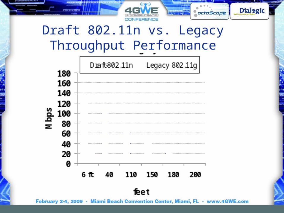
Draft 802.11n vs. Legacy Throughput Performance

802.11n Throughput Enhancements802.11n throughput enhancement Description
Throughput enhancement over legacy
Spatial multiplexing With 2 spatial streams throughput can be double that of a single stream. 100%
40 MHz channel width
Doubling the channel width over the legacy 20 MHz channel can double the throughput.
100%
More efficient OFDM
With 52 data sub-carriers vs. 48 for the legacy networks, the highest data rate per stream is 65 Mbps vs. the 802.11a/g 54 Mbps
20%
Shorter GI
The short GI of 400 ns allowed by 802.11n reduces the symbol time from 4 microseconds to 3.6 microseconds increasing the symbol rate by 10%.
10%
Frame aggregation and Block ACK 64k bytes A-MPDU; 8k bytes A-MSDU Up to 100%

IEEE 802.11a,b,g,n
20 MHz Channel 40 MHz Channel
1 stream 2 streams 1 stream 2 streams
Data Rate, in Mbps
802.11b 2.4 GHz
1, 2, 5.5, 11
802.11a 5 GHz
6, 9, 12, 18, 24, 36, 48, 54
802.11g 2.4 GHz
1, 2, 6, 9, 12, 18, 24, 36, 48, 54
802.11nGI[1]=800ns 2.4 GHz
6.5, 13, 19.5, 26, 39, 52, 58.5, 65
13, 26, 39, 52, 78, 104, 117, 130
802.11nGI[1]=800ns 5 GHz
6.5, 13, 19.5, 26, 39, 52, 58.5, 65
13, 26, 39, 52, 78, 104, 117, 130
13.5, 27, 40.5, 54, 81, 108, 121.5, 135
27, 54, 81, 108, 162, 216, 243, 270
802.11n, GI=400ns 2.4 and 5 GHz
7.2, 14.4, 21.7, 28.9, 43.3, 57.8, 65, 72.2
14.4, 28.9, 43.3, 57.8, 86.7, 115.6, 130, 144.4
15, 30, 45, 60, 90, 120, 135, 150
30, 60, 90, 120, 180, 240, 270, 300
[1,] GI = Guard Interval, period within an OFDM symbol allocated to letting the signal settle prior to transmitting the next symbol. Legacy 802.11a/b/g devices use 800ns GI. GI of 400ns is optional for 802.11n.
16
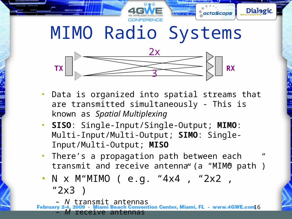
MIMO Radio Systems
• Data is organized into spatial streams that are transmitted simultaneously - This is known as Spatial Multiplexing
• SISO: Single-Input/Single-Output; MIMO: Multi-Input/Multi-Output; SIMO: Single-Input/Multi-Output; MISO
• There’s a propagation path between each transmit and receive antenna (a “MIMO path”)
• N x M MIMO ( e.g. “4x4”, “2x2”, “2x3”)– N transmit antennas– M receive antennas– Total of N x M paths
TX RX
2x3

clusters
Mobile reflector
Mobile device
MIMO transmission uses multipath to send two or more streams

18
Indoor MIMO Multipath Channel• Multipath reflections come in
“clusters”• Reflections in a cluster arrive
at a receiver all from the same general direction
• Statistics of clusters are key to MIMO system operation
• 802.11n developed 6 models: A through F
Wall
Reflector
Moving reflector
Direct ray
Tx
Rx
Reflector
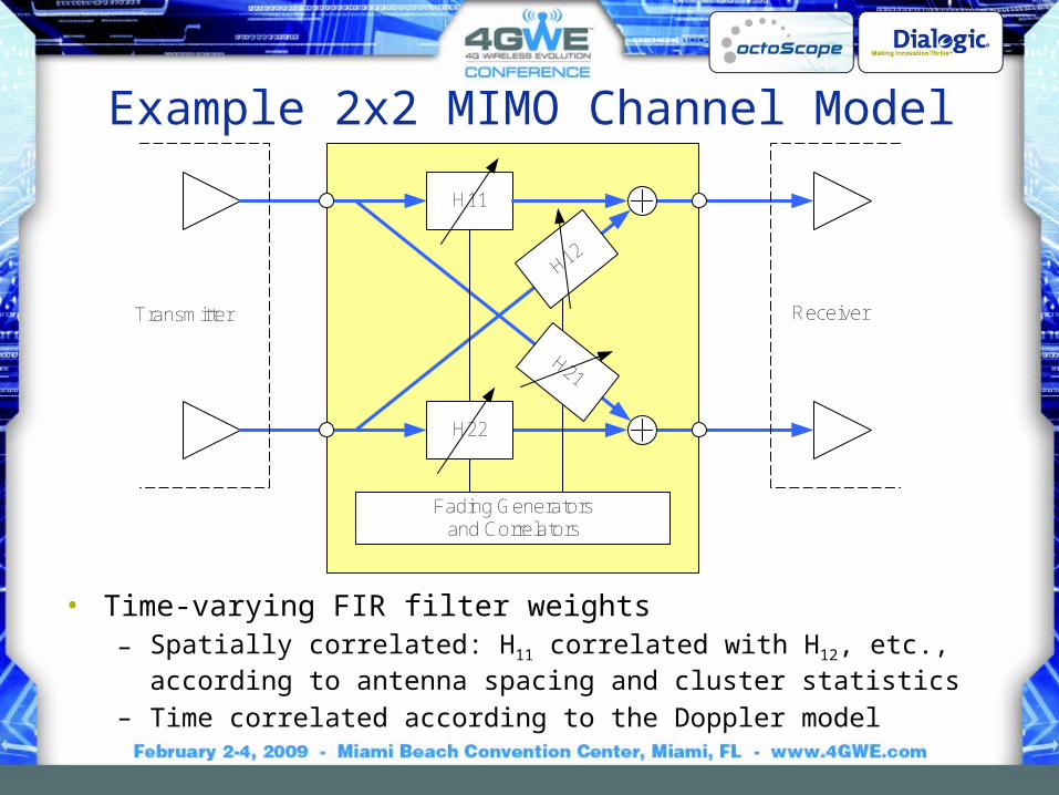
Example 2x2 MIMO Channel Model
• Time-varying FIR filter weights– Spatially correlated: H11 correlated with H12, etc., according to antenna
spacing and cluster statistics– Time correlated according to the Doppler model
H11
H22
H12
H21
Fading Generatorsand Correlators
Transmitter Receiver

MIMO Channel Emulation
• 4 x 4 MIMO paths to support 802.11n• WiMAX requires 2 x 2• 802.11n and ITU M.1225 channel models • Bidirectionality required to support beamforming
Up-down convertersDSP

Municipal Multipath Environment

Outdoor Multipath Environment
• One or two dominant paths in outdoor environments – fewer paths and less scattering than indoors
Base Station(BS)
picocell radius: r < 100 mmicro: 100 m < r < 1 000 mmacro: r > 1 000 m

802.11n Channel Models
• Delay spread is a function of the size of the modeled environment• Number of clusters represents number of independent propagation
paths modeled• Doppler spectrum assumes reflectors moving in environment at 1.2
km/h, which corresponds to about 6 Hz in 5 GHz band, 3 Hz in 2.4 GHz band
Parameters A B C D E FAvg 1st Wall Distance (m) 5 5 5 10 20 30RMS Delay Spread (ns) 0 15 30 50 100 150Maximum Delay (ns) 0 80 200 390 730 1050Number of Taps 1 9 14 18 18 18Number of Clusters N/A 2 2 3 4 6
Models

ITU MIMO Channel Models – For BWA
Channel Model Path 1 Path 2 Path 3 Path 4 Path 5 Path 6
ITU Pedestrian B(relative figures)
0 dB0 ns
-0.9 dB200 ns
-4.9 dB800 ns
-8.0 dB1200 ns
-7.8 dB2300 ns
-23.9 dB3700 ns
ITU Vehicular A(relative figures)
0 dB0 ns
-1.0 dB310 ns
-9.0 dB710 ns
-10.0 dB1090 ns
-15.0 dB1730 ns
-20.0 dB2510 ns
Channel Model Speed Probability
ITU Pedestrian B 3 km/hr 60%
ITU Vehicular A 30 km/hr 30%
120 km/hr 10%
WiMAX system performance simulations are based on ITU models
BWA = Broadband Wireless Access

Lightly Regulated Band for 802.11, 802.16
• March 2005 FCC offered 50 MHz 3650 to 3700 MHz for contention-based protocol
• 802.11y meets FCC requirement; 802.16h is working to comply
• 21st century regulation geared for digital communications– multiple services to share
the band in an orderly way
300 Million licensesone for every person or company
$300 per license for 10 years
Registered stations (base stations): 1 W/MHz, ~15 km
Unregistered stations (handsets, laptops): 40 mW/MHz, 1-1.5 km

IEEE 802.11 Timeline
1997 1998 1999 2000 2001 2002 2003 2004 2005 2006 2007 2008 2009 2010
802.11-1997 IEEE Standard
802.11-1999 IEEE Standard
July 1997
April 1999 802.11-2007 IEEE Standard
TGk TGma
TGn TGp
TGr TGs
TGT TGu
TGv TGw TGy
TGa TGb TGb-cor1
TGc TGd TGe
TGF TGg
TGh TGi
TGj
Part of 802.1
withdrawn
June 2007

Making 802.11 Enterprise-grade
• 802.11r– Fast Roaming
√ released
• 802.11k– Radio Resource Measurement
√ released
• 802.11v– Wireless Network Management

802.11r Fast Transition (Roaming)• Needed by voice applications• Basic methodology involves
propagating authentication information for connected stations through the ‘mobility domain’ to eliminate the need for re-authentication upon station transition from one AP to another
• The station preparing the roam can setup the target AP to minimize the actual transition time

802.11k Radio Resource Measurement
• Impetus for 802.11k came from the Enterprises that needed to manage their WLANs from a central point
• 802.11k makes a centralized network management system by providing layer 2 mechanisms for– Discovering network topology– Monitoring WLAN devices, their receive power levels, PHY
configuration and network activity
• Can be used to assists 802.11r Fast Transition (roaming) protocol with handoff decisions based on the loading of the infrastructure, but 802.11v is more focused on load balancing

802.11v Wireless Network Management
• TGv’s charter is to build on the network measurement mechanisms defined by TGk and introduce network management functions to provide Enterprises with centralized network management and load balancing capabilities.
• Major goals: manageability, improved power efficiency and interference avoidance
• Defines a protocol for requesting and reporting location capability– Location information may be CIVIC (street
address) or GEO (longitude, latitude coordinates) • For the handset, TGv may enable awareness of
AP e911 capabilities while the handset is in sleep mode; this work has common ground with TGu

802.11v Improves Power Efficiency• TGv defines FBMS (flexible broadcast
multicast service) - the mechanism to let devices extend their sleep period
• Devices can specifying the wake up interval to be longer than a single DTIM (delivery traffic indication message). This consolidates traffic receive/transmit intervals and extends battery life of handsets.

Making Wi-Fi Carrier-grade?• 802.11u - InterWorking with External
Networks– Main goal is to enable Interworking with
external networks, including other 802 based networks such as 802.16 and 802.3 and 3GPP based IMS networks
– Manage network discovery, emergency call support (e911), roaming, location and availability
– The network discovery capabilities give a station looking to connect information about networks in range, service providers, subscription status with service providers
• 802.11u makes 802.11 networks more like cellular networks where such information is provided by the infrastructure

802.11p Wireless Access Vehicular Environment (WAVE)
• Transportation communications systems under development by Department of Transportation (DoT)
• 802.11p is the PHY in the Intelligent Transportation Systems (ITS)
• WAVE is also known as DSRC (Dedicated Short Range Communications)
• WAVE/DSRC is the method for vehicle-to-vehicle and vehicle to road-side unit communications to support…– Public safety– Collision avoidance– Traffic awareness and management– Traveler information– Toll booth payments

• Operates in the 5.9 GHz frequency band dedicated by the FCC for WAVE/DSRC
• This band falls right above the 802.11a band, making it supportable by the commercial 802.11a chipsets
Lower Layers
Networking Services
Upper Layers
WAVE Service Security
IEEE 1609.1, et al.
IEEE 1609.3
IEEE 1609.4, IEEE 802.11p
WAVE device
Medium
IEEE 1609.2
802.11p Wireless Access Vehicular Environment (WAVE)

Wireless Mesh
Traditional WLAN
Mesh Mesh links
Client links
Wired links
Mesh Portal
Wired connection to each AP 802.11s802.16j (relay)802.16m (built-in meshing)802.15.5BWA backhaul mesh

IEEE 802.11s Mesh• Wireless Distribution System with
automatic topology learning and wireless path configuration
• Self-forming, self-healing, dynamic routing
• ~32 nodes to make routing algorithms computationally manageable
• Extension of 802.11i security and 802.11e QoS protocol to operate in a distributed rather than centralized topology
Mesh Portal
MP (Mesh Point)

802.11s Mesh Enhanced StationsMultiple association capability reduces hops between server and client stations

Fast Handoff in Dynamic Meshes• To support VoIP, 802.11s needs to incorporate the fast
handoff mechanisms defined in 802.11r. – Enable stations to roam from one mesh AP to another within
approximately 50 ms without noticeable degradation in the quality of a voice call
– In a dynamic mesh (e.g. in vehicles) MPs may be roaming with respect to other MPs and the 802.11s standard requires fast roaming of MPs with respect to one another.

802.11s Security• 802.11s has to make special provisions for security. In the
traditional fixed infrastructure stations authenticate through APs with a centralized AAA server.
• In a mesh network MPs have to mutually authenticate with one another. 802.11s security features extend 802.11i to peer-to-peer environment.

IEEE 802.16 and 802.15 Mesh Standards
• 802.16j and 802.15.5are also standardizing mesh topologies
• 802.16j is not an ad-hoc mesh, but a relay to extend the range between a CPE and a base station
• 802.16m has meshing protocol built in
Wireless relay

Cellular Microwave Backhaul Mesh
• Microwave backhaul for base stations can be configured in PTP, PTMP, mesh, and ring topologies.
• NGMN* (www.ngmn.org) and 3GPP are considering the mesh architecture due to its high resiliency and redundancy.
41
Microwave
Fiber access
Fiber capacity
MSC
Microwavehub
* NGMN is an organization of major operators that defines high level requirements for 3GPP.

IEEE 802.16 Active Task Groups
• 802.16h, License-Exempt Task Group – Working with 802.11 TGy and 802.19 Coexistence TAG
• 802.16j, Mobile Multihop Relay– Extended reach between BS (base station) and CPE (customer
premises equipment)
• 802.16m, IMT Advanced Air Interface• Maintenance
– Developing 802.16Rev2– Working with the WiMAX Forum
http://grouper.ieee.org/groups/802/16

WiMAX Forum• IEEE 802.16 contains too many options• The WiMAX Forum defines certification profiles on parts of the standard
selected for deployment; promotes interoperability of products through testing and certification
• The WiMAX Forum works closely with the IEEE 802.16 Maintenance group to refine the standard as the industry learns from certification testing
Release 1.0 802.16e/TDD
Release 1.5 802.16e/TDD and FDD
Release 2.0 802.16m (IMT Advanced)
current
Under development
Future

Mobility and Handoff• Two basic requirements for
mobility– Location management:
tracking where a mobile station (MS) is at any time
– Handoff management: ensuring a seamless transition for the current session as the MS moves out of the coverage range of one base station and into the range of another

Location Management• The MS periodically informs the network of
its current location: location registration• Location area usually includes one or more
base stations• Needs to be done frequently to ensure
accurate information is recorded about the location of each MS
• When an incoming call arrives at the network, the paging process is initiated
• The recipient's current location is retrieved from a database and the base stations in that area page the subscriber

Handoff • WiMAX requires handoff latency be
less than 50ms with an associated packet loss of less than 1 percent for speeds up to 120kmph
• The MS makes the decisions while the BS makes recommendations on target BS’s for the handoff
• Either the SINR (Signal to Interference plus Noise Ratio) or RSS (receive signal strength) can be used as criteria

Voice Requirements• Packet loss, especially bursty packet loss, causes poor
signal quality• Delay and jitter (variation in delay) can also cause loss of
quality• 200 ms events (signal loss or delay) are audible to the ear• In wireless networks, bursty packet loss can be due to
– Congestion in the infrastructure– Client roaming from one AP to another
~100 microsecondpackets, depending on CODEC
~20-30 millisecond gaps
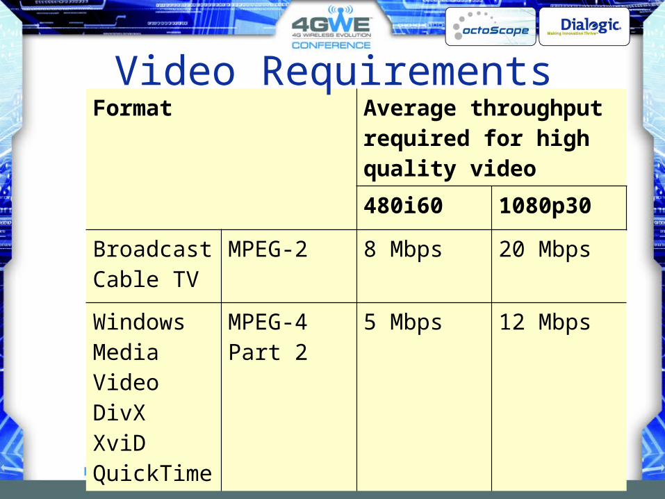
Format Average throughput required for high quality video
480i60 1080p30
BroadcastCable TV
MPEG-2 8 Mbps 20 Mbps
Windows Media VideoDivXXviDQuickTime
MPEG-4 Part 2
5 Mbps 12 Mbps
Video Requirements

Video Surveillance• Required throughput
is a function of video frame rate, resolution and color
• Approximately 2 Mbps needed for full VGA, 7 frames/sec

802 Wireless• 802.11
– Faster (802.11n, ac/ad)– More power efficient (sleep modes 802.11n, u, v)– Location aware (802.11u, v)– VoIP and Video capable– Manageable
• 802.16– Scalable, supports mobility – 802.16m has built in meshing and femtocell support
• White spaces – Major new disruptive market – Currently no industry standard other than FCC

Agenda10:30 – 12:00 noon Our G-enealogy – History and Evolution of
Mobile Radio Lunch
1:00 – 2:00 The IEEE’s Wireless Ethernet Keeps Going and Growing
2:00 – 2:45 4G Tutorial: Vive la Différence?Break
3:00 – 3:45 Mobile Broadband - New Applications and New Business ModelsBreak
4:00 – 4:45 Tutorial: White Spaces and Beyond

4G Starts in the Home
xDSL, CableMetro Ethernet
Broadband IP access

Th
rou
gh
pu
t
# subscribers, throughput
Cell size shrinks as throughput and usage increase

Ethernet
xDSL, CableMetro Ethernet
Home AP/router
Broadband IP access
Wi-Fi
?
Femtocell
Femtocells allow the use of ordinary cell phones over broadband IP access
Wi-Fi enabled cell phones can work via Wi-Fi APs
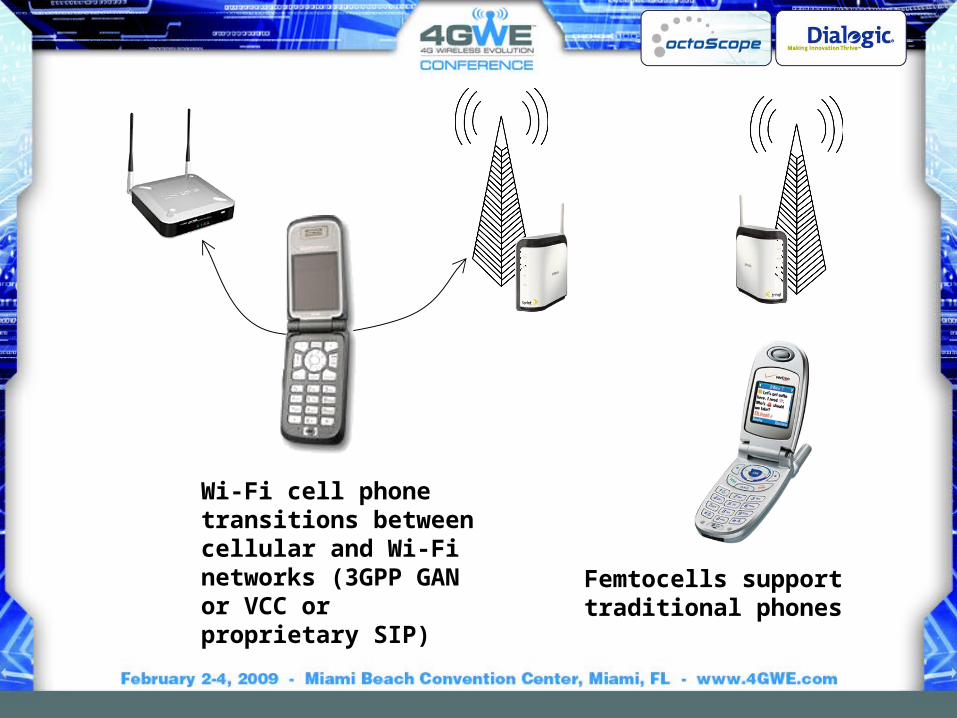
Wi-Fi cell phone transitions between cellular and Wi-Fi networks (3GPP GAN or VCC or proprietary SIP)
Femtocells support traditional phones

GAN (Generic Access Network) / UMA (Unlicensed Mobile Access)
Dual-ModeUMA
Handset
BaseStation
Controller(BSC)
IP Network
UMANetwork
Controller(UNC)
GSM Radio Access Network (RAN)
Unlicensed Mobile Access Network (UMAN)
CoreMobileNetwork
Operators and vendors agreed to develop UMA in December 2003
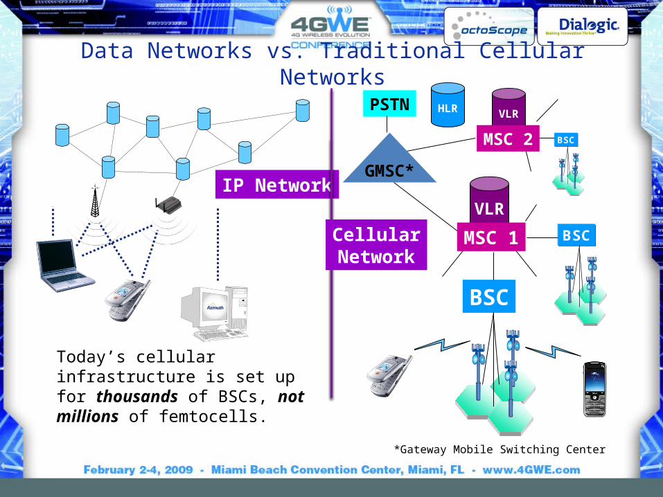
Data Networks vs. Traditional Cellular Networks
VLR
VLR
BSC
BSC
BSC
MSC 1
HLR
GMSC*
PSTN
MSC 2
*Gateway Mobile Switching Center
IP Network
CellularNetwork
Today’s cellular infrastructure is set up for thousands of BSCs, not millions of femtocells.

TraditionalCellularNetwork
Bill
ing/
OS
S
QoS
Pre
senc
e
Bill
ing/
OS
S
QoS
Pre
senc
e
FixedMobile
IP Network
FixedMobile
IP Network
Billing/OSSBilling/OSS
QoSQoS
PresencePresence
Traditional “Stovepipe” IMS
Stovepipe model – replicates functionality
IMS – common layers facilitate adding services
Voice Internet Video …Voice Internet
… IMSNetwork
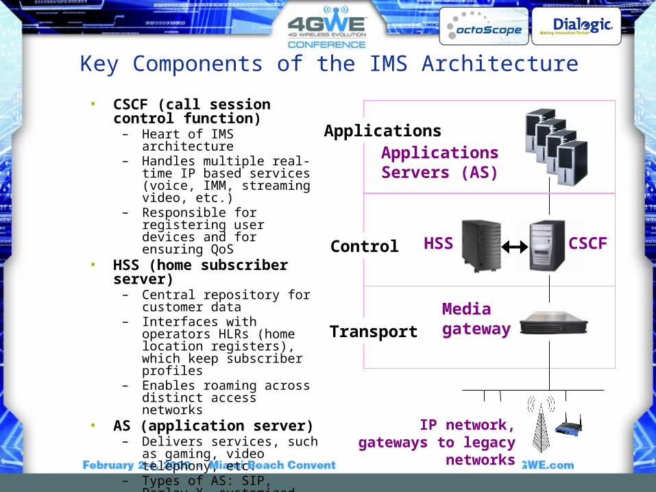
Key Components of the IMS Architecture
• CSCF (call session control function)
– Heart of IMS architecture– Handles multiple real-time IP
based services (voice, IMM, streaming video, etc.)
– Responsible for registering user devices and for ensuring QoS
• HSS (home subscriber server)
– Central repository for customer data
– Interfaces with operators HLRs (home location registers), which keep subscriber profiles
– Enables roaming across distinct access networks
• AS (application server)– Delivers services, such as
gaming, video telephony, etc.– Types of AS: SIP, Parlay X,
customized legacy AS
CSCFHSS
Applications Servers (AS)
MediagatewayTransport
Control
Applications
IP network, gateways to legacy networks
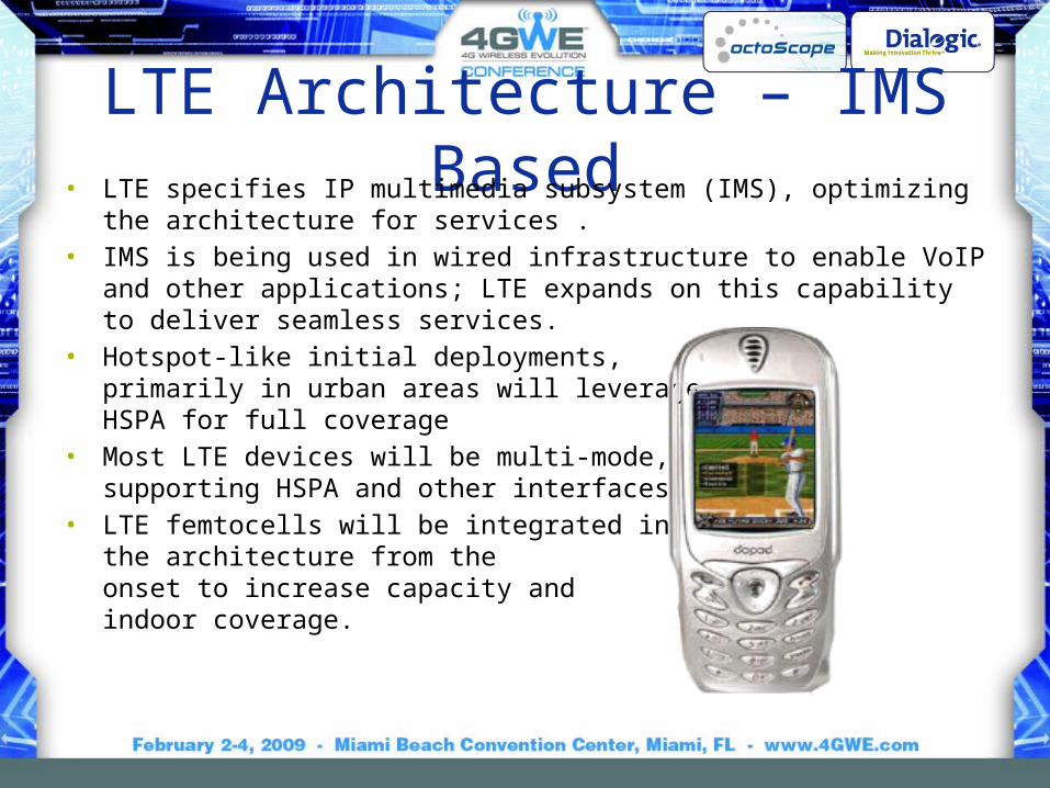
LTE Architecture – IMS Based• LTE specifies IP multimedia subsystem (IMS), optimizing the architecture for
services .• IMS is being used in wired infrastructure to enable VoIP and other
applications; LTE expands on this capability to deliver seamless services.• Hotspot-like initial deployments,
primarily in urban areas will leverageHSPA for full coverage
• Most LTE devices will be multi-mode, supporting HSPA and other interfaces
• LTE femtocells will be integrated in the architecture from the onset to increase capacity and indoor coverage.

Japan
USA
3GPP (3rd Generation Partnership Project)
• Partnership of 6 regional standards groups, which translate 3GPP specifications to regional standards
• ITU references the regional standards
61

Operator Influence on LTE• LTE was built around the features and
capabilities defined by Next Generation Mobile Networks (NGMN) Alliance (www.ngmn.org)
– Operator buy-in from ground-up
• LTE/SAE (Service Architecture Evolution) Trial Initiative (LSTI) formed through the cooperation of vendors and operators to begin testing LTE early in the development process (www.lstiforum.org)
• NGMN defines the requirements • LSTI conducts testing to ensure
conformance.
62
formed 9/2006 by major operators:Sprint NextelChina Mobile VodafoneOrange T-Mobile KPN Mobile NTT DoCoMo

LTE and WiMAX Modulation and Access
• CDMA (code division multiple access) is a coding and access scheme
– CDMA, W-CDMA, CDMA-2000
• SDMA (space division multiple access) is an access scheme– MIMO, beamforming, sectorized antennas
• TDMA (time division multiple access) is an access scheme– AMPS, GSM
• FDMA (frequency division multiple access) is an access scheme• OFDM (orthogonal frequency division multiplexing) is a modulation
scheme• OFDMA (orthogonal frequency division multiple access) is a
modulation and access scheme

FDMA
…TDMA
Frequency
Pow
er OFDM
Multiple orthogonal carriers
Time
Pow
er
Channel
Frequency
User 1 User 2 User 3 User 4 User 5

FDMA vs. OFDMA• OFDMA is more frequency efficient
than FDMA– Each station is assigned a set of
subcarriers, eliminating frequency guard bands between users
FDMA OFDMA
ChannelGuard band

Frequency
Pow
er Fixed OFDMA
Frequency
Tim
e Dynamic OFDMA
Frequency allocation per user is continuous vs. time
Frequency allocation per user is dynamically allocated vs. time slots
WiMAXLTE
User 1 User 2 User 3 User 4 User 5

Key Features of WiMAX and LTE• OFDMA (Orthogonal Frequency Division Multiple Access)• Users are allocated a slice in time and frequency• Flexible, dynamic per user resource allocation• Base station scheduler for uplink and downlink resource allocation
– Resource allocation information conveyed on a frame‐by frame basis
• Support for TDD (time division duplex) and FDD (frequency division duplex)
DLUL
DL
ULFDDPaired channels
TDD: single frequency channel for uplink and downlink

TDD Transmission
Sub
chan
nel
Fre
quen
cy
OFDMA symbol number Time

H-FDD (half-duplex FDD) Transmission
Fre
quen
cy
Time

SDMA = Smart Antenna Technologies
• Beamforming– Use multiple-antennas to spatially shape
the beam to improve coverage and capacity
• Spatial Multiplexing (SM) or Collaborative MIMO– Multiple streams are transmitted over
multiple antennas– Multi-antenna receivers separate the
streams to achieve higher throughput – In uplink single-antenna stations can
transmit simultaneously• Space-Time Code (STC)
– Transmit diversity such as Alamouti code [1,2] reduces fading
2x2 Collaborative MIMO increases the peak data rate two-fold by transmitting two data streams.

ScalabilityWiMAX
Channel bandwidth (MHz)
1.25 5 10 20 3.5 7 8.75
Sample time (ns) 714.3 178.6 89.3 44.6 250 125 100
FFT size 128 512 1024 2048 512 1024 1024
Sampling factor (ch bw/sampling freq)
28/25 8/7
Subcarrier spacing (kHz)
10.9375 7.8125 9.766
Symbol time (usec) 91.4 128 102.4
LTE
Channel bandwidth (MHz)
1.4 3 5 10 15 20
FFT size 128 258 512 1024 1536 2048

3G/4G ComparisonPeak Data Rate (Mbps) Access time
(msec)Downlink Uplink
HSPA (today) 14 Mbps 2 Mbps 50-250 msec
HSPA (Release 7) MIMO 2x2 28 Mbps 11.6 Mbps 50-250 msec
HSPA + (MIMO, 64QAM Downlink)
42 Mbps 11.6 Mbps 50-250 msec
WiMAX Release 1.0 TDD (2:1 UL/DL ratio), 10 MHz channel
40 Mbps 10 Mbps 40 msec
LTE (Release 8), 5+5 MHz channel
43.2 Mbps 21.6 Mbps 30 msec

HSPA and HSPA+• HSPA+ is aimed at extending operators’ investment in HSPA
– 2x2 MIMO, 64 QAM in the downlink, 16 QAM in the uplink – Data rates up to 42 MB in the downlink and 11.5 MB in the uplink.
• HSPA+ is CDMA-based and lacks the efficiency of OFDM
One-tunnel architecture flattens the network by enabling a direct transport path for user data between RNC and the GGSN, thus minimizing delays and set-up time
ServingGPRS Support Node
Gateway GPRS Support Node
Radio Network Controller
Control Data
User Data
Traditional HSPA
One tunnel HSPA
One tunnel HSPA+
Node B Node B
RNC
Node B
SGSN
GGSN GGSN GGSN
RNC
SGSNSGSN
RNC

LTE SAE (System Architecture Evolution)
eNode-B
MME
SAE, PDN
Trusted non-3GPP IP Access (CDMA, TD-SCDMA, WiMAX)
Wi-Fi
IP Services (IMS)
GPRS CoreSGSNHSS
PCRF
SGSN (Serving GPRS Support Node)PCRF (policy and charging enforcement function) HSS (Home Subscriber Server)MME (Mobility Management Entity)SAE (System Architecture Evolution)PDN (Public Data Network)

EPS (Evolved Packet System)• EPS is the core network for LTE and other advanced RAN
technologies – Flat IP architecture minimizes round trip time (RTT) to <10
ms and setup time to <100 ms– Higher data rates, seamless interworking between 3GPP
and non-3GPP networks and IMS– Primary elements are eNodeB, MME (Mobility Management
Entity) and the SAE gateway• MME provides connectivity between the eNodeB and the legacy
GSM and UMTS networks via SGSN*. The MME also supports the following: user equipment context and identity, authorization, and authentication.
• The SAE gateway, or EPS access gateway, provides the PDN (packet data network) gateway and serving gateway functions.
Not hierarchical
as GSMEDGEHSPA
*GPRS Gateway Support Node Serving GPRS Support Node
eNode-B
MME
SAE GWPDN GW
SGSN

Backhaul• LTE requires high-capacity links
between eNodeB and the core. The options are:
– Existing fiber deployments – Microwave in locations where fiber
is unavailable– Ethernet
• Co-location of LTE with legacy networks means the backhaul has to support
– GSM/UMTS/HSPA/LTE or LTE/CDMA – Time division multiplexing (TDM),
asynchronous transfer mode (ATM) and Ethernet traffic
• NGMN wants to standardize backhaul in order to reduce cost while meeting stringent synchronization requirements.
Non-TDM backhaul solutions may be unable to maintain the strict timing required for cellular backhaul.
Backhaul is the key to reducing TCO for operators.

Multi-Protocol Label Switching (MPLS) Backhaul
• MPLS is being considered for backhauling– Supports TDM, ATM, and Ethernet simultaneously– Incorporates RSVP-TE (Resource Reservation
Protocol-Traffic Engineering) for end-to-end QoS – Enables RAN sharing via the use of VPNs
• BS (base stations) could act as edge MPLS routers, facilitating migration to pure IP.
GbE
HSPA
eNode-B
WiMAX

WiMAX vs. LTE• Commonalities
– IP-based– OFDMA and MIMO– Similar data rates and channel widths
• Differences– Carriers are able to set requirements for LTE through
organizations like NGMN and LSTI, but cannot do this as easily at the IEEE based 802.16
– LTE backhaul is designed to support legacy services while WiMAX is better suited to greenfield deployments

Commercial IssuesLTE
• Deployments likely slower than projected
But• Eventual migration
path for GSM/3GSM, i.e. for > 80% share
• Will be lowest cost & dominant in 2020
WiMAX• 2-3 year lead, likely
maintained for years• Dedicated spectrum
in many countries
But• Likely < 15% share by
2020 & thus more costly

Agenda10:30 – 12:00 noon Our G-enealogy – History and Evolution of
Mobile Radio Lunch
1:00 – 2:00 The IEEE’s Wireless Ethernet Keeps Going and Growing
2:00 – 2:45 4G Tutorial: Vive la Différence? Break
3:00 – 3:45 Mobile Broadband - New Applications and New Business ModelsBreak
4:00 – 4:45 Tutorial: White Spaces and Beyond

www.octoscope.com
Brough Turner, Chief Strategy Officer, [email protected]
Blog: http://blogs.nmss.com/communications/
[email protected] Skype: brough

AdditionalReferenceMaterial
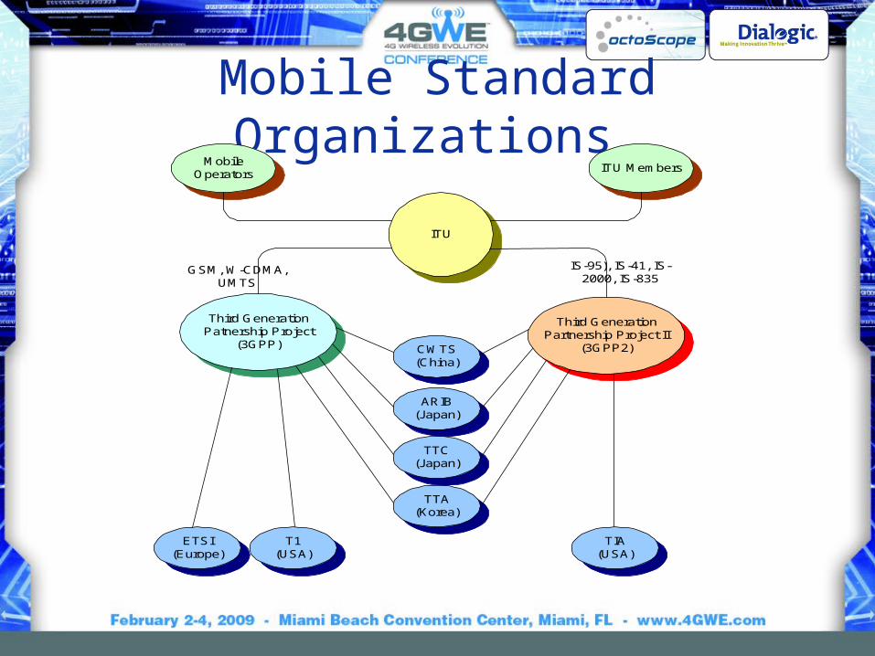
Mobile Standard Organizations
ARIB(Japan)
T1(USA)
ETSI(Europe)
TTA(Korea)
CWTS(China)
TTC(Japan)
TIA(USA)
Third GenerationPatnership Project
(3GPP)
Third GenerationPartnership Project II
(3GPP2)
ITU
MobileOperators
ITU Members
IS-95), IS-41, IS-2000, IS-835
GSM, W-CDMA,UMTS

Partnership Projects and Forums • ITU IMT-2000: http://www.itu.int/home/imt.html • Mobile Partnership Projects
– 3GPP : http://www.3gpp.org– 3GPP2 : http://www.3gpp2.org
• Mobile marketing alliances and forums– GSM Association: http://www.gsmworld.com/index.shtml – UMTS Forum : http://www.umts-forum.org – CDMA Development Group: http://www.cdg.org/index.asp – Next Generation Mobile Networks Alliance: http://www.ngmn.org/ – Global Mobile Suppliers Association: http://www.gsacom.com– CTIA: http://www.ctia.org/ – 3G Americas: http://www.uwcc.org

Mobile Standards Organizations• European Technical Standard Institute (Europe):
– http://www.etsi.org
• Telecommunication Industry Association (USA):– http://www.tiaonline.org
• Alliance for Telecommunications Industry Solutions (USA)(formerly Committee T1):
– http://www.t1.org & http://www.atis.org/
• China Communications Standards Association (China):– http://www.cwts.org
• The Association of Radio Industries and Businesses (Japan):– http://www.arib.or.jp/english/index.html
• The Telecommunication Technology Committee (Japan):– http://www.ttc.or.jp/e/index.html
• The Telecommunication Technology Association (Korea):– http://www.tta.or.kr/english/e_index.htm

Other Industry Consortia• OMA, Open Mobile Alliance:
http://www.openmobilealliance.org/– Consolidates Open Mobile Architecture, WAP Forum, Location
Interoperability Forum, SyncML, MMS Interoperability Group, Wireless Village
• Lists of wireless organizations compiled by others:– http://www.wipconnector.com/resources.php – http://focus.ti.com/general/docs/wtbu/wtbugencontent.tsp?templ
ateId=6123&contentId=4602
– http://www.wlana.org/pdf/wlan_standards_orgs.pdf
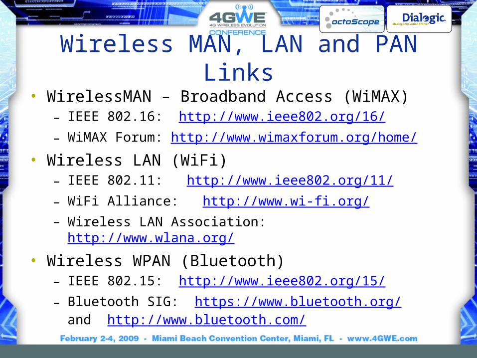
Wireless MAN, LAN and PAN Links• WirelessMAN – Broadband Access (WiMAX)
– IEEE 802.16: http://www.ieee802.org/16/ – WiMAX Forum: http://www.wimaxforum.org/home/
• Wireless LAN (WiFi)– IEEE 802.11: http://www.ieee802.org/11/ – WiFi Alliance: http://www.wi-fi.org/ – Wireless LAN Association: http://www.wlana.org/
• Wireless WPAN (Bluetooth)– IEEE 802.15: http://www.ieee802.org/15/ – Bluetooth SIG: https://www.bluetooth.org/
and http://www.bluetooth.com/

Market & Subscriber Statistics
Free:• http://en.wikipedia.org/wiki/List_of_mobile_network_operators
– http://en.wikipedia.org/wiki/List_of_mobile_network_operators_of_Europe– http://en.wikipedia.org/wiki/List_of_mobile_network_operators_of_the_Americas– http://en.wikipedia.org/wiki/List_of_mobile_network_operators_of_the_Asia_Pacific_region– http://en.wikipedia.org/wiki/List_of_mobile_network_operators_of_the_Middle_East_and_Afric
a
• http://www.gsmworld.com/roaming/gsminfo/index.shtml • http://www.cdg.org/worldwide/cdma_world_subscriber.asp • http://www.gsacom.com/news/statistics.php4
Nominal cost:• http://www.itu.int/ITU-D/ict/publications/world/world.html
www.octoscope.com
Brough Turner, Chief Strategy Officer, [email protected]
Blog: http://blogs.nmss.com/communications/
[email protected] Skype: brough

AdditionalContent

ITU-T Voice Quality Standards• MOS (mean opinion score) uses a
wide range of human subjects to provide a subjective quality score (ITU-T P.800)
• PESQ (perceptual speech quality measure) sends a voice pattern across a network and then compares received pattern to the original pattern and computes the quality rating (ITU-T P.862)
• R-Factor (Rating factor) computed based on delay packet loss and other network performance parameters; R-Factor directly translates into MOS (ITU-T G.107)

ITU-T PESQ Model
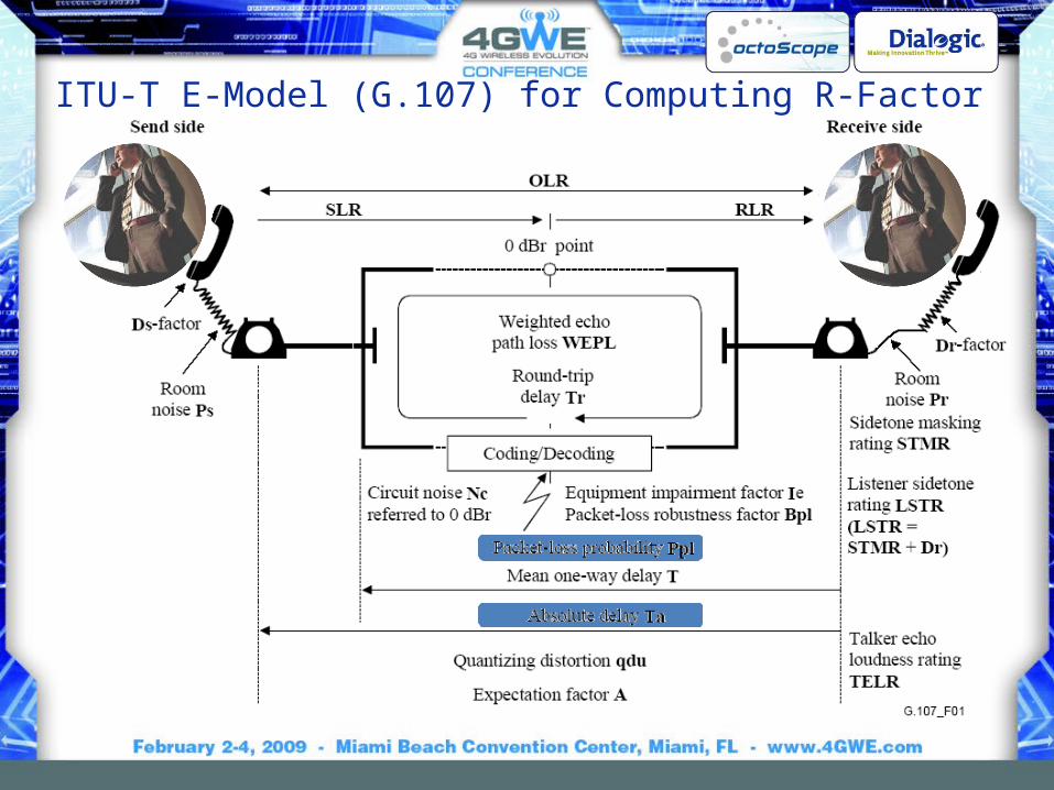
ITU-T E-Model (G.107) for Computing R-Factor

Parameter Abbr. UnitDefault Value
Permitted Range
Send Loudness Rating SLR dB +8 0 … +18
Receive Loudness Rating RLR dB +2 -5 … +14
Sidetone Masking Rating STMR dB 15 10 … 20
Listener Sidetone Rating LSTR dB 18 13 … 23
D-Value of Telephone, Send Side Ds - 3 -3 … +3
D-Value of Telephone Receive Side Dr - 3 -3 … +3
Talker Echo Loudness Rating TELR dB 65 5 …65
Weighted Echo Path Loss WEPL dB 110 5 ... 110
Mean one-way Delay of the Echo Path T ms 0 0 … 500
Round-Trip Delay in a 4-wire Loop Tr ms 0 0 … 1000
Absolute Delay in echo-free Connections Ta ms 0 0 … 500
Number of Quantization Distortion Units qdu - 1 1 … 14
Equipment Impairment Factor Ie - 0 0 … 40
Packet-loss Robustness Factor Bpl - 1 1 … 40
Random Packet-loss Probability Ppl % 0 0 … 20
Circuit Noise referred to 0 dBr-point Nc dBmOp -70 -80 … -40
Noise Floor at the Receive Side Nfor dBmp -64 -
Room Noise at the Send Side Ps dB(A) 35 35 … 85
Room Noise at the Receive Side Pr dB(A) 35 35 … 85Advantage Factor A - 0 0 … 20
G.1
07 –
Def
ault
val
ues
an
d
per
mit
ted
ran
ges
fo
r th
e E
-m
od
el
par
am
eter
s

R-Factor to MOS Conversion
Toll quality
MO
S
R-Factor

Video Metrics• Media Delivery Index (MDI) defined in
RFC 4445 describes media capacity of a network composed of the Media Loss Rate (MLR) and Delay Factor (DF)– MLR is a media-weighted metric that
expresses the number of expected IEEE Std 802.11 packets dropped from a video stream
– DF represents the amount of time required to drain the endstation buffer at the bit rate of the media stream
• MLR = (Packets Expected - Packets Received) / Interval in Seconds
• DF is calculated as follows:– VB = |Bytes Received - Bytes Drained|– DF = (max(VB) – min(VB)) / Video Bit
rate in Bytes– Where VB = video buffer