wireless lans - the cisco learning network - cisco certification
TRANSCRIPT
C H A P T E R 11
Wireless LANs
So far, this book has dedicated a lot of attention to (wired) Ethernet LANs. Although they are vitally important, another style of LAN, wireless LANs (WLAN), fills a particularly important role in providing network access to end users. In particular, WLANs allow the user to communicate over the network without requiring any cables, enabling mobile devices while removing the expense and effort involved in running cables. This chapter examines the basic concepts, standards, installation, and security options for some of the most common WLAN technologies today.
As a reminder if you’re following the optional reading plan listed in the Introduction to this book, you will be moving on to Chapter 1 of the CCNA ICND2 Official Exam Certification Guide following this chapter.
“Do I Know This Already?” QuizThe “Do I Know This Already?” quiz allows you to assess whether you should read the entire chapter. If you miss no more than one of these nine self-assessment questions, you might want to move ahead to the “Exam Preparation Tasks” section. Table 11-1 lists the major headings in this chapter and the “Do I Know This Already?” quiz questions covering the material in those sections. This helps you assess your knowledge of these specific areas. The answers to the “Do I Know This Already?” quiz appear in Appendix A.
Table 11-1 “Do I Know This Already?” Foundation Topics Section-to-Question Mapping
Foundation Topics Section Questions
Wireless LAN Concepts 1–4
Deploying WLANs 5–7
Wireless LAN Security 8, 9

300 Chapter 11: Wireless LANs
1. Which of the following IEEE wireless LAN standards uses only the U-NII band of frequencies (around 5.4 GHz)?
a. 802.11a
b. 802.11b
c. 802.11g
d. 802.11i
2. Which of the following answers is the correct maximum speed at which two IEEE WLAN devices can send data with a particular standard?
a. 802.11b, using OFDM, at 54 Mbps
b. 802.11g, using OFDM, at 54 Mbps
c. 802.11a, using DSSS, at 54 Mbps
d. 802.11a, using DSSS, at 11 Mbps
3. Which of the following lists the nonoverlapping channels when using 802.1b DSSS in the U.S.?
a. 1, 2, 3
b. 1, 5, 9
c. 1, 6, 11
d. a, b, g
e. 22, 33, 44
4. Which of the following terms refers to a WLAN mode that allows a laptop to roam between different access points?
a. ESS
b. BSS
c. IBSS
d. None of the other answers are correct.
5. When configuring a wireless access point, which of the following are typical configuration choices?
a. SSID
b. The speed to use

“Do I Know This Already?” Quiz 301
c. The wireless standard to use
d. The size of the desired coverage area
6. Which of the following is true about an ESS’s connections to the wired Ethernet LAN?
a. The AP connects to the Ethernet switch using a crossover cable.
b. The various APs in the same WLAN need to be assigned to the same VLAN by the Ethernet switches.
c. The APs must have an IP address configured to forward traffic.
d. The APs using mixed 802.11g mode must connect via a Fast Ethernet or faster
connection to an Ethernet switch.
7. Which of the following are not common reasons why a newly installed WLAN does not allow a client to connect through the WLAN into the wired infrastructure?
a. The AP is installed on top of a metal filing cabinet.
b. The client is near a fast-food restaurant’s microwave oven.
c. The client is sitting on top of a big bundle of currently used Cat5 Ethernet cables.
d. The AP was configured to use DSSS channel 1 instead of the default channel 6,
and no one configured the client to use channel 6.
8. Which of the following WLAN security standards refer to the IEEE standard?
a. WPA
b. WPA2
c. WEP
d. 802.11i
9. Which of the following security features were not in the original WEP security standard but are now in the WPA2 security standard?
a. Dynamic key exchange
b. Preshared Keys (PSK)
c. 802.1x authentication
d. AES encryption
302 Chapter 11: Wireless LANs
Foundation Topics
This chapter examines the basics of WLANs. In particular, the first section introduces the concepts, protocols, and standards used by many of the most common WLAN installations today. The chapter then examines some basic installation steps. The last major section looks at WLAN security, which is particularly important because the WLAN signals are much more susceptible to being intercepted by an attacker than Ethernet LANs.
Wireless LAN ConceptsMany people use WLANs on a regular basis today. PC sales continue to trend toward more laptop sales versus desktop computers, in part to support a more mobile workforce. PC users need to connect to whatever network they are near, whether at work, at home, in a hotel, or at a coffee shop or bookstore. The migration toward a work model in which you find working moments wherever you are, with a need to be connected to the Internet at any time, continues to push the growth of wireless LANs.
For example, Figure 11-1 shows the design of a LAN at a retail bookstore. The bookstore provides free Internet access via WLANs while also supporting the bookstore’s devices via a wired LAN.
The wireless-capable customer laptops communicate with a WLAN device called an access point (AP). The AP uses wireless communications to send and receive frames with the WLAN clients (the laptops). The AP also connects to the same Ethernet LAN as the bookstore’s own devices, allowing both customers and employees to communicate with other sites.
This section begins the chapter by explaining the basics of WLANs, starting with a comparison of similarities between Ethernet LANs and WLANs. The rest of the section then explores some of the main differences.
Comparisons with Ethernet LANsWLANs are similar to Ethernet LANs in many ways, the most important being that WLANs allow communications to occur between devices. The IEEE defines standards for both, using the IEEE 802.3 family for Ethernet LANs and the 802.11 family for WLANs. Both standards define a frame format with a header and trailer, with the header including a source and destination MAC address field, each 6 bytes in length. Both define rules about how the devices should determine when they should send frames and when they should not.

Wireless LAN Concepts 303
Figure 11-1 Sample WLAN at a Bookstore
The biggest difference between the two lies in the fact that WLANs use radiated energy waves, generally called radio waves, to transmit data, whereas Ethernet uses electrical signals flowing over a cable (or light on optical cabling). Radio waves pass through space, so technically there is no need for any physical transmission medium. In fact, the presence of matter—in particular, walls, metal objects, and other obstructions—gets in the way of the wireless radio signals.
Several other differences exist as well, mainly as a side effect of the use of wireless instead of wires. For example, Chapter 7, “Ethernet LAN Switching Concepts,” explains how Ethernet can support full-duplex (FDX) communication if a switch connects to a single device rather than a hub. This removes the need to control access to the link using carrier sense multiple access collision detect (CSMA/CD). With wireless, if more than one device at a time sends radio waves in the same space at the same frequency, neither signal is intelligible, so a half-duplex (HDX) mechanism must be used. To arbitrate the use of the frequency, WLANs use the carrier sense multiple access with collision avoidance (CSMA/CA) algorithm to enforce HDX logic and avoid as many collisions as possible.
AccessPointRadio
Cell
PC2PC1
EmployeePC
CashRegister
SW1
SW2
To the Rest of theNetwork and the Internet
EthernetCable

304 Chapter 11: Wireless LANs
Wireless LAN StandardsAt the time this book was published, the IEEE had ratified four major WLAN standards: 802.11, 802.11a, 802.11b, and 802.11g. This section lists the basic details of each WLAN standard, along with information about a couple of other standards bodies. This section also briefly mentions the emerging 802.1n standard, which the IEEE had not yet ratified by the time this book was published.
Four organizations have a great deal of impact on the standards used for wireless LANs today. Table 11-2 lists these organizations and describes their roles.
Of the organizations listed in this table, the IEEE develops the specific standards for the different types of WLANs used today. Those standards must take into account the frequency choices made by the different worldwide regulatory agencies, such as the FCC in the U.S. and the ITU-R, which is ultimately controlled by the United Nations (UN).
The IEEE introduced WLAN standards with the creation of the 1997 ratification of the 802.11 standard. This original standard did not have a suffix letter, whereas later WLAN standards do. This naming logic, with no suffix letter in the first standard, followed by other standards with a suffix letter, is like the original IEEE Ethernet standard. That standard was 802.3, with later, more-advanced standards having a suffix, such as 802.3u for Fast Ethernet.
The original 802.11 standard has been replaced by more-advanced standards. In order of ratification, the standards are 802.11b, 802.11a, and 802.11g. Of note, the 802.11n standard is likely to be ratified by the end of 2008, with prestandard products available in 2007. Table 11-3 lists some key points about the currently ratified standards.
Table 11-2 Organizations That Set or Influence WLAN Standards
Organization Standardization Role
ITU-R Worldwide standardization of communications that use radiated energy, particularly managing the assignment of frequencies
IEEE Standardization of wireless LANs (802.11)
Wi-Fi Alliance An industry consortium that encourages interoperability of products that implement WLAN standards through their Wi-Fi certified program
Federal Communications Commission (FCC)
The U.S. government agency with that regulates the usage of various communications frequencies in the U.S.

Wireless LAN Concepts 305
*These values assume a WLAN in the U.S.
This table lists a couple of features that have not yet been defined but that are described in this chapter.
Modes of 802.11 Wireless LANsWLANs can use one of two modes—ad hoc mode or infrastructure mode. With ad hoc mode, a wireless device wants to communicate with only one or a few other devices directly, usually for a short period of time. In these cases, the devices send WLAN frames directly to each other, as shown in Figure 11-2.
Figure 11-2 Ad Hoc WLAN
In infrastructure mode, each device communicates with an AP, with the AP connecting via wired Ethernet to the rest of the network infrastructure. Infrastructure mode allows the WLAN devices to communicate with servers and the Internet in an existing wired network, as shown earlier in Figure 11-1.
Table 11-3 WLAN Standards
Feature 802.11a 802.11b 802.11g
Year ratified 1999 1999 2003
Maximum speed using DSSS — 11 Mbps 11 Mbps
Maximum speed using OFDM 54 Mbps — 54 Mbps
Frequency band 5 GHz 2.4 GHz 2.4 GHz
Channels (nonoverlapped)* 23 (12) 11 (3) 11 (3)
Speeds required by standard (Mbps) 6, 12, 24 1, 2, 5.5, 11 6, 12, 24
NOTE Devices in an infrastructure WLAN cannot send frames directly to each other; instead, they send frames to the AP, which can then in turn forward the frames to another WLAN device.
PC1 PC2

306 Chapter 11: Wireless LANs
Infrastructure mode supports two sets of services, called service sets. The first, called a Basic Service Set (BSS), uses a single AP to create the wireless LAN, as shown in Figure 11-1. The other, called Extended Service Set (ESS), uses more than one AP, often with overlapping cells to allow roaming in a larger area, as shown in Figure 11-3.
Figure 11-3 Infrastructure Mode BSS and ESS WLANs
The ESS WLANs allow roaming, which means that users can move around inside the coverage area and stay connected to the same WLAN. As a result, the user does not need to change IP addresses. All the device has to do is sense when the radio signals from the current AP are getting weaker; find a new, better AP with a stronger or better signal; and start using the new AP.
PC2PC1
EmployeePC
CashRegister
SW1
SW2
To the Rest of theNetwork and the Internet
RadioCell
RadioCell
EthernetCable
AP1
PC4PC3
EthernetCable
AP2

Wireless LAN Concepts 307
Table 11-4 summarizes the WLAN modes for easy reference.
Wireless Transmissions (Layer 1)WLANs transmit data at Layer 1 by sending and receiving radio waves. The WLAN network interface cards (NIC), APs, and other WLAN devices use a radio and its antenna to send and receive the radio waves, making small changes to the waves to encode data. Although the details differ significantly compared to Ethernet, the idea of encoding data by changing the energy signal that flows over a medium is the same idea as Ethernet encoding.
Similar to electricity on copper wires and light over optical cables, WLAN radio waves have a repeating signal that can be graphed over time, as shown in Figure 11-4. When graphed, the curve shows a repeating periodic waveform, with a frequency (the number of times the waveform repeats per second), amplitude (the height of the waveform, representing signal strength), and phase (the particular point in the repeating waveform). Of these items, frequency, measured in hertz (Hz), is the most important in discussions of WLANs.
Figure 11-4 Graph of an 8-KHz Signal
Many electronic devices radiate energy at varying frequencies, some related to the device’s purpose (for example, a wireless LAN or a cordless telephone). In other cases the radiated energy is a side effect. For example, televisions give off some radiated energy. To prevent
Table 11-4 Different WLAN Modes and Names
Mode Service Set Name Description
Ad hoc Independent Basic Service Set (IBSS)
Allows two devices to communicate directly. No AP is needed.
Infrastructure (one AP) Basic Service Set (BSS)
A single wireless LAN created with an AP and all devices that associate with that AP.
Infrastructure (more than one AP)
Extended Service Set (ESS)
Multiple APs create one wireless LAN, allowing roaming and a larger coverage area.
.001 Seconds
Frequency = 8000 Hz
308 Chapter 11: Wireless LANs
the energy radiated by one device from interfering with other devices, national government agencies, regulate and oversee the frequency ranges that can be used inside that country. For example, the Federal Communications Commission (FCC) in the U.S. regulates the electromagnetic spectrum of frequencies.
The FCC or other national regulatory agencies specify some ranges of frequencies, called frequency bands. For example, in the U.S., FM and AM radio stations must register with the FCC to use a particular range (band) of frequencies. A radio station agrees to transmit its radio signal at or under a particular power level so that other radio stations in other cities can use the same frequency band. However, only that one radio station can use a particular frequency band in a particular location.
A frequency band is so named because it is actually a range of consecutive frequencies. An FM radio station needs about 200 kilohertz (KHz) of frequency in which to send a radio signal. When the station requests a frequency from the FCC, the FCC assigns a base frequency, with 100 KHz of bandwidth on either side of the base frequency. For example, an FM radio station that announces something like “The greatest hits are at 96.5 FM” means that the base signal is 96.5 megahertz (MHz), with the radio transmitter using the frequency band between 96.4 MHz and 96.6 MHz, for a total bandwidth of .2 MHz, or 200 KHz.
The wider the range of frequencies in a frequency band, the greater the amount of information that can be sent in that frequency band. For example, a radio signal needs about 200 KHz (.2 MHz) of bandwidth, whereas a broadcast TV signal, which contains a lot more information because of the video content, requires roughly 4.5 MHz.
The FCC, and equivalent agencies in other countries, license some frequency bands, leaving some frequency bands unlicensed. Licensed bands are used for many purposes; the most common are AM and FM radio, shortwave radio (for example, for police department communications), and mobile phones. Unlicensed frequencies can be used by all kinds of devices; however, the devices must still conform to the rules set up by the regulatory agency. In particular, a device using an unlicensed band must use power levels at or below a particular setting. Otherwise, the device might interfere too much with other devices sharing that unlicensed band. For example, microwave ovens happen to radiate energy in the 2.4 gigahertz (GHz) unlicensed band as a side effect of cooking food. That same unlicensed band is used by some WLAN standards and by many cordless telephones. In some cases, you cannot hear someone on the phone or surf the Internet using a WLAN when someone’s heating up dinner.
NOTE The use of the term bandwidth to refer to speeds of network interfaces is just a holdover from the idea that the width (range) of a frequency band is a measurement of how much data can be sent in a period of time.

Wireless LAN Concepts 309
The FCC defines three unlicensed frequency bands. The bands are referenced by a particular frequency in the band, although by definition, a frequency band is a range of frequencies. Table 11-5 lists the frequency bands that matter to some degree for WLAN communications.
Wireless Encoding and Nonoverlapping DSSS ChannelsWhen a WLAN NIC or AP sends data, it can modulate (change) the radio signal’s frequency, amplitude, and phase to encode a binary 0 or 1. The details of that encoding are beyond the scope of this book. However, it is important to know the names of three general classes of encoding, in part because the type of encoding requires some planning and forethought for some WLANs.
Frequency Hopping Spread Spectrum (FHSS) uses all frequencies in the band, hopping to different ones. By using slightly different frequencies for consecutive transmissions, a device can hopefully avoid interference from other devices that use the same unlicensed band, succeeding at sending data at some frequencies. The original 802.11 WLAN standards used FHSS, but the current standards (802.11a, 802.11b, and 802.11g) do not.
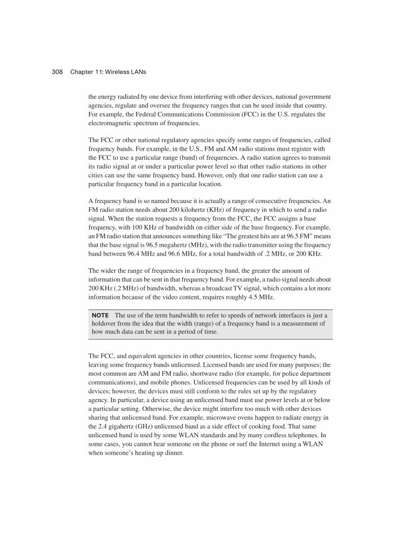
Direct Sequence Spread Spectrum (DSSS) followed as the next general class of encoding type for WLANs. Designed for use in the 2.4 GHz unlicensed band, DSSS uses one of several separate channels or frequencies. This band has a bandwidth of 82 MHz, with a range from 2.402 GHz to 2.483 GHz. As regulated by the FCC, this band can have 11 different overlapping DSSS channels, as shown in Figure 11-5.
Although many of the channels shown in the figure overlap, three of the channels (the channels at the far left and far right, and the channel in the center) do not overlap enough to impact each other. These channels (channels 1, 6, and 11) can be used in the same space for WLAN communications, and they won’t interfere with each other.
Table 11-5 FCC Unlicensed Frequency Bands of Interest
Frequency Range Name Sample Devices
900 KHz Industrial, Scientific, Mechanical (ISM)
Older cordless telephones
2.4 GHz ISM Newer cordless phones and 802.11, 802.11b, 802.11g WLANs
5 GHz Unlicensed National Information Infrastructure (U-NII)
Newer cordless phones and 802.11a, 802.11n WLANs
310 Chapter 11: Wireless LANs
Figure 11-5 Eleven Overlapping DSSS Channels at 2.4 GHz
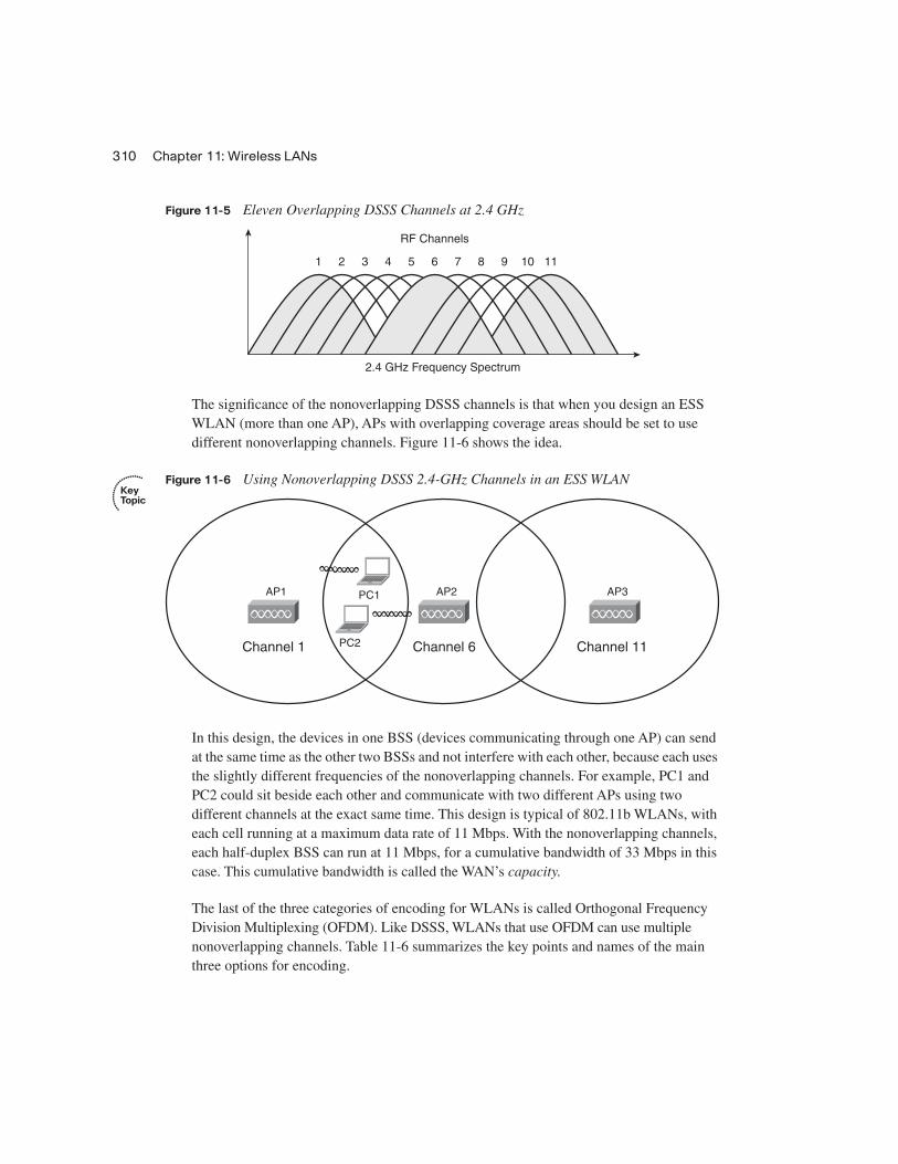
The significance of the nonoverlapping DSSS channels is that when you design an ESS WLAN (more than one AP), APs with overlapping coverage areas should be set to use different nonoverlapping channels. Figure 11-6 shows the idea.
Figure 11-6 Using Nonoverlapping DSSS 2.4-GHz Channels in an ESS WLAN
In this design, the devices in one BSS (devices communicating through one AP) can send at the same time as the other two BSSs and not interfere with each other, because each uses the slightly different frequencies of the nonoverlapping channels. For example, PC1 and PC2 could sit beside each other and communicate with two different APs using two different channels at the exact same time. This design is typical of 802.11b WLANs, with each cell running at a maximum data rate of 11 Mbps. With the nonoverlapping channels, each half-duplex BSS can run at 11 Mbps, for a cumulative bandwidth of 33 Mbps in this case. This cumulative bandwidth is called the WAN’s capacity.
The last of the three categories of encoding for WLANs is called Orthogonal Frequency Division Multiplexing (OFDM). Like DSSS, WLANs that use OFDM can use multiple nonoverlapping channels. Table 11-6 summarizes the key points and names of the main three options for encoding.
1 2 3 4 5 6
RF Channels
2.4 GHz Frequency Spectrum
7 8 9 10 11
AP3
Channel 11
AP2
Channel 6
AP1
Channel 1 PC2
PC1

Wireless LAN Concepts 311
Wireless InterferenceWLANs can suffer from interference from many sources. The radio waves travel through space, but they must pass through whatever matter exists inside the coverage area, including walls, floors, and ceilings. Passing through matter causes the signal to be partially absorbed, which reduces signal strength and the size of the coverage area. Matter can also reflect and scatter the waves, particularly if there is a lot of metal in the materials, which can cause dead spots (areas in which the WLAN simply does not work), and a smaller coverage area.
Additionally, wireless communication is impacted by other radio waves in the same frequency range. The effect is the same as trying to listen to a radio station when you’re taking a long road trip. You might get a good clear signal for a while, but eventually you drive far enough from the radio station’s antenna that the signal is weak, and it is hard to hear the station. Eventually, you get close enough to the next city’s radio station that uses the same frequency range, and you cannot hear either station well because of the interference. With WLANs, the interference may simply mean that the data only occasionally makes it through the air, requiring lots of retransmissions, and resulting in poor efficiency.
One key measurement for interference is the Signal-to-Noise Ratio (SNR). This calculation measures the WLAN signal as compared to the other undesired signals (noise) in the same space. The higher the SNR, the better the WLAN devices can send data successfully.
Coverage Area, Speed, and CapacityA WLAN coverage area is the space in which two WLAN devices can successfully send data. The coverage area created by a particular AP depends on many factors, several of which are explained in this section.
First, the transmit power by an AP or WLAN NIC cannot exceed a particular level based on the regulations from regulatory agencies such as the FCC. The FCC limits the transmit power to ensure fairness in the unlicensed bands. For example, if two neighbors bought Linksys APs and put them in their homes to create a WLAN, the products would conform
Table 11-6 Encoding Classes and IEEE Standard WLANs
Name of Encoding Class What It Is Used By
Frequency Hopping Spread Spectrum (FHSS) 802.11
Direct Sequence Spread Spectrum (DSSS) 802.11b
Orthogonal Frequency Division Multiplexing (OFDM) 802.11a, 802.11g
NOTE The emerging 802.11n standard uses OFDM as well as multiple antennas, a technology sometimes called multiple input multiple output (MIMO).

312 Chapter 11: Wireless LANs
to FCC regulations. However, if one person bought and installed high-gain antennas for her AP, and greatly exceeded the FCC regulations, she might get a much wider coverage area—maybe even across the whole neighborhood. However, it might prevent the other person’s AP from working at all because of the interference from the overpowered AP.
The materials and locations of the materials near the AP also impact an AP’s coverage area. For example, putting the AP near a large metal filing cabinet increases reflections and scattering, which shrinks the coverage area. Certainly, concrete construction with steel rebar reduces the coverage area in a typical modern office building. In fact, when a building’s design means that interference will occur in some areas, APs may use different types of antennas that change the shape of the coverage area from a circle to some other shape.
As it turns out, weaker wireless signals cannot pass data at higher speeds, but they can pass data at lower speeds. So, WLAN standards support the idea of multiple speeds. A device near the AP may have a strong signal, so it can transmit and receive data with the AP at higher rates. A device at the edge of the coverage area, where the signals are weak, may still be able to send and receive data—although at a slower speed. Figure 11-7 shows the idea of a coverage area, with varying speeds, for an IEEE 802.11b BSS.
The main ways to increase the size of the coverage area of one AP are to use specialized antennas and to increase the power of the transmitted signal. For example, you can increase the antenna gain, which is the power added to the radio signal by the antenna. To double the coverage area, the antenna gain must be increased to quadruple the original gain. Although this is useful, the power output (the EIRP) must still be within FCC rules (in the U.S.).
The actual size of the coverage area depends on a large number of factors that are beyond the scope of this book. Some of the factors include the frequency band used by the WLAN standard, the obstructions between and near the WLAN devices, the interference from other sources of RF energy, the antennas used on both the clients and APs, and the options used by DSSS and OFDM when encoding data over the air. Generally speaking, WLAN standards that use higher frequencies (U-NII band standards 802.11a and the future 802.11n) can send data faster, but with the price of smaller coverage areas. To cover all the required space, an ESS that uses higher frequencies would then require more APs, driving up the cost of the WLAN deployment.
NOTE The power of an AP is measured based on the Effective Isotropic Radiated Power (EIRP) calculation. This is the radio’s power output, plus the increase in power caused by the antenna, minus any power lost in the cabling. In effect, it’s the power of the signal as it leaves the antenna.

Wireless LAN Concepts 313
Figure 11-7 Coverage Area and Speed
Table 11-7 lists the main IEEE WLAN standards that had been ratified at the time this book was published, the maximum speed, and the number of nonoverlapping channels.
*The speeds listed in bold text are required speeds according to the standards. The other speeds are optional.
Finally, note that the number of (mostly) nonoverlapping channels supported by a standard, as shown in Figures 11-5 and 11-6, affects the combined available bandwidth. For example, in a WLAN that exclusively uses 802.11g, the actual transmissions could occur at 54 Mbps. But three devices could sit beside each other and send at the same time, using three different
Table 11-7 WLAN Speed and Frequency Reference
IEEE StandardMaximum Speed (Mbps)
Other Speeds* (Mbps) Frequency
Nonoverlapping Channels
802.11b 11 Mbps 1, 2, 5.5 2.4 GHz 3
802.11a 54 Mbps 6, 9, 12, 18, 24, 36, 48 5 GHz 12
802.11g 54 Mbps Same as 802.11a 2.4 GHz 3
NOTE The original 802.11 standard supported speeds of 1 and 2 Mbps.
1 Mbps
2 Mbps
5.5 Mbps
11 Mbps

314 Chapter 11: Wireless LANs
channels, to three different APs. Theoretically, that WLAN could support a throughput of 3 * 54 Mbps, or 162 Mbps, for these devices in that part of the WLAN. Along the same line of reasoning, an 802.11a WLAN can transmit data at 54 Mbps, but with 12 nonoverlapping channels, for a theoretical maximum of 12 * 54 Mbps = 648 Mbps of bandwidth capacity.
Media Access (Layer 2)Ethernet LANs began life using a shared medium (a coaxial cable), meaning that only one device could send data at a time. To control access to this half-duplex (HDX) medium, Ethernet defined the use of the CSMA/CD algorithm. As Ethernet progressed with continually improved standards, it started using switches, with one device cabled to each switch port, allowing the use of full duplex (FDX). With FDX, no collisions can occur, so the CSMA/CD algorithm is disabled.
With wireless communications, devices cannot be separated onto different cable segments to prevent collisions, so collisions can always occur, even with more-advanced WLAN standards. In short, if two or more WLAN devices send at the same time, using overlapping frequency ranges, a collision occurs, and none of the transmitted signals can be understood by those receiving the signal. To make matters worse, the device that is transmitting data cannot concurrently listen for received data. So, when two WLAN devices send at the same time, creating a collision, the sending devices do not have any direct way to know the collision occurred.
The solution to the media access problem with WLANs is to use the carrier sense multiple access with collision avoidance (CSMA/CA) algorithm. The collision avoidance part minimizes the statistical chance that collisions could occur. However, CSMA/CA does not prevent collisions, so the WLAN standards must have a process to deal with collisions when they do occur. Because the sending device cannot tell if its transmitted frame collided with another frame, the standards all require an acknowledgment of every frame. Each WLAN device listens for the acknowledgment, which should occur immediately after the frame is sent. If no acknowledgment is received, the sending device assumes that the frame was lost or collided, and it resends the frame.
The following list summarizes the key points about the CSMA/CA algorithm, omitting some of the details for the sake of clarity:
Step 1 Listen to ensure that the medium (space) is not busy (no radio waves currently are being received at the frequencies to be used).
Step 2 Set a random wait timer before sending a frame to statistically reduce the chance of devices all trying to send at the same time.
Step 3 When the random timer has passed, listen again to ensure that the medium is not busy. If it isn’t, send the frame.

Deploying WLANs 315
Step 4 After the entire frame has been sent, wait for an acknowledgment.
Step 5 If no acknowledgment is received, resend the frame, using CSMA/CA logic to wait for the appropriate time to send again.
This concludes the brief introduction to wireless LAN concepts. Next, this chapter covers the basics of what you should do when installing a new wireless LAN.
Deploying WLANsWLAN security is one of the more important features of WLANs, and for good reason. The same security exposures exist on WLANs as for Ethernet LANs, plus WLANs are exposed to many more vulnerabilities than wired Ethernet LANs. For example, someone could park outside a building and pick up the WLAN signals from inside the building, reading the data. Therefore, all production WLAN deployments should include the currently best security options for that WLAN.
Although security is vitally important, the installation of a new WLAN should begin with just getting the WLAN working. As soon as a single wireless device is talking to an AP, security configuration can be added and tested. Following that same progression, this section examines the process of planning and implementing a WLAN, with no security enabled. The final major section of this chapter, “Wireless LAN Security,” examines the concepts behind WLAN security.
Wireless LAN Implementation ChecklistThe following basic checklist can help guide the installation of a new BSS WLAN:
Step 1 Verify that the existing wired network works, including DHCP services, VLANs, and Internet connectivity.
Step 2 Install the AP and configure/verify its connectivity to the wired network, including the AP’s IP address, mask, and default gateway.
Step 3 Configure and verify the AP’s wireless settings, including Service Set Identifier (SSID), but no security.
Step 4 Install and configure one wireless client (for example, a laptop), again with no security.
Step 5 Verify that the WLAN works from the laptop.
Step 6 Configure wireless security on the AP and client.
Step 7 Verify that the WLAN works again, in the presence of the security features.

316 Chapter 11: Wireless LANs
This section examines the first five tasks. The last major section of this chapter discusses the concepts behind WLAN security but does not explain the large number of detailed options for configuring WLAN security.
Step 1: Verify the Existing Wired NetworkMost of the other chapters in this book explain the details of how to understand, plan, design, and implement the switches and routers that create the rest of the network, so there is no need to repeat those details here. However, it can be helpful to consider a couple of items related to testing an existing wired network before connecting a new WLAN.
First, the Ethernet switch port to which the AP’s Ethernet port connects typically is a switch access port, meaning that it is assigned to a particular VLAN. Also, in an ESS design with multiple APs, all the Ethernet switch ports to which the APs attach should be in the same VLAN. Figure 11-8 shows a typical ESS design for a WLAN, with the VLAN IDs listed.
Figure 11-8 ESS WLAN with All APs in Ethernet VLAN 2
To test the existing network, you could simply connect a laptop Ethernet NIC to the same Ethernet cable that will be used for the AP. If the laptop can acquire an IP address, mask, and other information using DHCP, and communicate with other hosts, the existing wired network is ready to accept the AP.
AP1
Channel 1
AP2
Channel 6
AP3
SW2VLAN 2
SW1VLAN 2
VLAN Trunk
VLAN 2
Channel 11

Deploying WLANs 317
Step 2: Install and Configure the AP’s Wired and IP DetailsJust like an Ethernet switch, wireless APs operate at Layer 2 and do not need an IP address to perform their main functions. However, just as an Ethernet switch in an Enterprise network should have an IP address so that it can be easily managed, APs deployed in an Enterprise network should also have an IP address.
The IP configuration details on an AP are the same items needed on an Ethernet switch, as covered in the section “Configuring the Switch IP Address” in Chapter 9, “Ethernet Switch Configuration.” In particular, the AP needs an IP address, subnet mask, default gateway IP address, and possibly the IP address of a DNS server.
The AP uses a straight-through Ethernet cable to connect to the LAN switch. Although any speed Ethernet interface works, when using the faster WLAN speeds, using a Fast Ethernet interface on a switch helps improve overall performance.
Step 3: Configure the AP’s WLAN DetailsMost of the time, WLAN APs can be installed with no configuration, and they work. For example, many homes have consumer-grade wireless APs installed, connected to a high-speed Internet connection. Often, the AP, router, and cable connection terminate in the same device, such as the Linksys Dual-Band Wireless A+G Broadband Router. (Linksys is a division of Cisco Systems that manufactures and distributes consumer networking devices.) Many people just buy these devices, plug in the power and the appropriate cables for the wired part of the connection, and leave the default WLAN settings, and the AP works.
Both consumer-grade and Enterprise-grade APs can be configured with a variety of parameters. The following list highlights some of the features mentioned earlier in this chapter that may need to be configured:
■ IEEE standard (a, b, g, or multiple)
■ Wireless channel
■ Service Set Identifier (SSID, a 32-character text identifier for the WLAN)
■ Transmit power
This chapter has already explained most of the concepts behind these four items, but the SSID is new. Each WLAN needs a unique name to identify the WLAN. Because a simple WLAN with a single AP is called a Basic Service Set (BSS), and a WLAN with multiple APs is called an Extended Service Set (ESS), the term for the identifier of a WLAN is the Service Set Identifier (SSID). The SSID is a 32-character ASCII text value. When you configure an ESS WLAN, each of the APs should be configured with the same SSID, which allows for roaming between APs, but inside the same WLAN.

318 Chapter 11: Wireless LANs
Also note that many APs today support multiple WLAN standards. In some cases, they can support multiple standards on the same AP at the same time. However, these mixed-mode implementations, particularly with 802.11b/g in this same AP, tend to slow down the WLAN. In practice, deploying some 802.11g-only APs and some mixed-mode b/g APs in the same coverage area may provide better performance than using only APs configured in b/g mixed mode.
Step 4: Install and Configure One Wireless ClientA wireless client is any wireless device that associates with an AP to use a WLAN. To be a WLAN client, the device simply needs a WLAN NIC that supports the same WLAN standard as the AP. The NIC includes a radio, which can tune to the frequencies used by the supported WLAN standard(s), and an antenna. For example, laptop computer manufacturers typically integrate a WLAN NIC into every laptop, and you can then use a laptop to associate with an AP and send frames.
The AP has several required configuration settings, but the client may not need anything configured. Typically, clients by default do not have any security enabled. When the client starts working, it tries to discover all APs by listening on all frequency channels for the WLAN standards it supports by default. For example, if a client were using the WLAN shown in Figure 11-6, with three APs, each using a different channel, the client might actually discover all three APs. The client would then use the AP from which the client receives the strongest signal. Also, the client learns the SSID from the AP, again removing the need for any client configuration.
WLAN clients may use wireless NICs from a large number of vendors. To help ensure that the clients can work with Cisco APs, Cisco started the Cisco Compatible Extensions Program (CCX). This Cisco-sponsored program allows any WLAN manufacturer to send its products to a third-party testing lab, with the lab performing tests to see if the WLAN NIC works well with Cisco APs. Cisco estimates that 95 percent of the wireless NICs on the market have been certified through this program.
With Microsoft operating systems, the wireless NIC may not need to be configured because of the Microsoft Zero Configuration Utility (ZCF). This utility, part of the OS, allows the PC to automatically discover the SSIDs of all WLANs whose APs are within range on the NIC. The user can choose the SSID to connect to. Or the ZCF utility can automatically pick the AP with the strongest signal, thereby automatically connecting to a wireless LAN without the user’s needing to configure anything.
Note that most NIC manufacturers also provide software that can control the NIC instead of the operating system’s built-in tools such as Microsoft ZCF.
Deploying WLANs 319
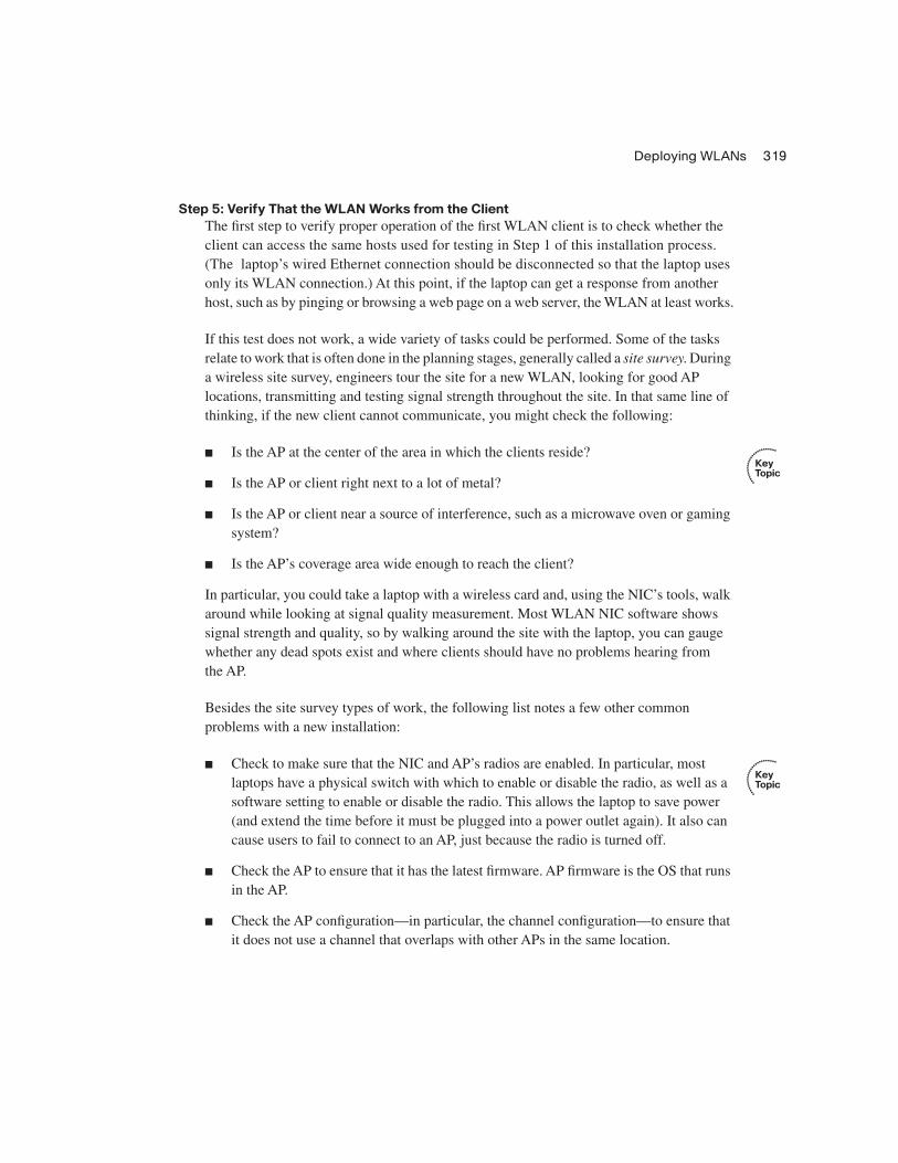
Step 5: Verify That the WLAN Works from the ClientThe first step to verify proper operation of the first WLAN client is to check whether the client can access the same hosts used for testing in Step 1 of this installation process. (The laptop’s wired Ethernet connection should be disconnected so that the laptop uses only its WLAN connection.) At this point, if the laptop can get a response from another host, such as by pinging or browsing a web page on a web server, the WLAN at least works.
If this test does not work, a wide variety of tasks could be performed. Some of the tasks relate to work that is often done in the planning stages, generally called a site survey. During a wireless site survey, engineers tour the site for a new WLAN, looking for good AP locations, transmitting and testing signal strength throughout the site. In that same line of thinking, if the new client cannot communicate, you might check the following:
■ Is the AP at the center of the area in which the clients reside?
■ Is the AP or client right next to a lot of metal?
■ Is the AP or client near a source of interference, such as a microwave oven or gaming system?
■ Is the AP’s coverage area wide enough to reach the client?
In particular, you could take a laptop with a wireless card and, using the NIC’s tools, walk around while looking at signal quality measurement. Most WLAN NIC software shows signal strength and quality, so by walking around the site with the laptop, you can gauge whether any dead spots exist and where clients should have no problems hearing from the AP.
Besides the site survey types of work, the following list notes a few other common problems with a new installation:
■ Check to make sure that the NIC and AP’s radios are enabled. In particular, most laptops have a physical switch with which to enable or disable the radio, as well as a software setting to enable or disable the radio. This allows the laptop to save power (and extend the time before it must be plugged into a power outlet again). It also can cause users to fail to connect to an AP, just because the radio is turned off.
■ Check the AP to ensure that it has the latest firmware. AP firmware is the OS that runs in the AP.
■ Check the AP configuration—in particular, the channel configuration—to ensure that it does not use a channel that overlaps with other APs in the same location.

320 Chapter 11: Wireless LANs
This completes the explanations of the first five steps of installing a simple wireless LAN. The final major section of this chapter examines WLAN security, which also completes the basic installation steps.
Wireless LAN SecurityAll networks today need good security, but WLANs have some unique security requirements. This section examines some of the security needs for WLANs and the progression and maturation of the WLAN security options. It also discusses how to configure the security features.
WLAN Security IssuesWLANs introduce a number of vulnerabilities that do not exist for wired Ethernet LANs. Some of these vulnerabilities give hackers an opportunity to cause harm by stealing information, accessing hosts in the wired part of the network, or preventing service through a denial-of-service (DoS) attack. Other vulnerabilities may be caused by a well-meaning but uninformed employee who installs an AP without the IT department’s approval, with no security. This would allow anyone to gain access to the rest of the Enterprise’s network.
The Cisco-authorized CCNA-related courses suggest several categories of threats:
■ War drivers: The attacker often just wants to gain Internet access for free. This person drives around, trying to find APs that have no security or weak security. The attacker can use easily downloaded tools and high-gain directional antennas (easily purchased and installed).
■ Hackers: The motivation for hackers is to either find information or deny services. Interestingly, the end goal may be to compromise the hosts inside the wired network, using the wireless network as a way to access the Enterprise network without having to go through Internet connections that have firewalls.
■ Employees: Employees can unwittingly help hackers gain access to the Enterprise network in several ways. An employee could go to an office supply store and buy an AP for less than $100, install the AP in his office, using default settings of no security, and create a small wireless LAN. This would allow a hacker to gain access to the rest of the Enterprise from the coffee shop across the street. Additionally, if the client does not use encryption, company data going between the legitimate employee client PC and the Enterprise network can be easily copied and understood by attackers outside the building.
■ Rogue AP: The attacker captures packets in the existing wireless LAN, finding the SSID and cracking security keys (if they are used). Then the attacker can set up her own AP, with the same settings, and get the Enterprise’s clients to use it. In turn, this can

Wireless LAN Security 321
cause the individuals to enter their usernames and passwords, aiding in the next phase of the attacker’s plan.
To reduce the risk of such attacks, three main types of tools can be used on a WLAN:
■ Mutual authentication
■ Encryption
■ Intrusion tools
Mutual authentication should be used between the client and AP. The authentication process uses a secret password, called a key, on both the client and the AP. By using some sophisticated mathematical algorithms, the AP can confirm that the client does indeed know the right key value. Likewise, the client can confirm that the AP also has the right key value. The process never sends the key through the air, so even if the attacker is using a network analysis tool to copy every frame inside the WLAN, the attacker cannot learn the key value. Also, note that by allowing mutual authentication, the client can confirm that the AP knows the right key, thereby preventing a connection to a rogue AP.
The second tool is encryption. Encryption uses a secret key and a mathematical formula to scramble the contents of the WLAN frame. The receiving device then uses another formula to decrypt the data. Again, without the secret encryption key, an attacker may be able to intercept the frame, but he or she cannot read the contents.
The third class of tools includes many options, but this class generally can be called intrusion tools. These tools include Intrusion Detection Systems (IDS) and Intrusion Prevention Systems (IPS), as well as WLAN-specific tools. Cisco defines the Structured Wireless-Aware Network (SWAN) architecture. It includes many tools, some of which specifically address the issue of detecting and identifying rogue APs, and whether they represent threats. Table 11-8 lists the key vulnerabilities, along with the general solution.
Table 11-8 WLAN Vulnerabilities and Solutions
Vulnerability Solution
War drivers Strong authentication
Hackers stealing information in a WLAN Strong encryption
Hackers gaining access to the rest of the network Strong authentication
Employee AP installation Intrusion Detection Systems (IDS), including Cisco SWAN
Rogue AP Strong authentication, IDS/SWAN
322 Chapter 11: Wireless LANs
The Progression of WLAN Security StandardsWLAN standards have progressed over the years in response to a growing need for stronger security and because of some problems in the earliest WLAN security standard. This section examines four significant sets of WLAN security standards in chronological order, describing their problems and solutions.
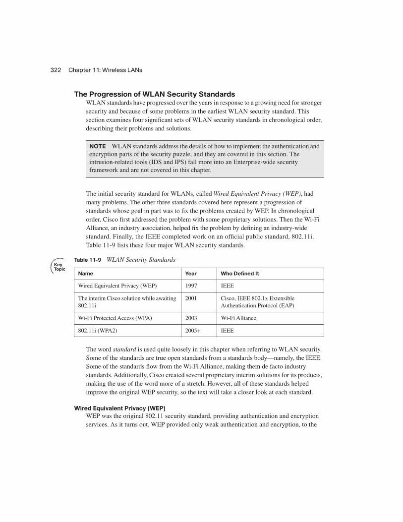
The initial security standard for WLANs, called Wired Equivalent Privacy (WEP), had many problems. The other three standards covered here represent a progression of standards whose goal in part was to fix the problems created by WEP. In chronological order, Cisco first addressed the problem with some proprietary solutions. Then the Wi-Fi Alliance, an industry association, helped fix the problem by defining an industry-wide standard. Finally, the IEEE completed work on an official public standard, 802.11i. Table 11-9 lists these four major WLAN security standards.
The word standard is used quite loosely in this chapter when referring to WLAN security. Some of the standards are true open standards from a standards body—namely, the IEEE. Some of the standards flow from the Wi-Fi Alliance, making them de facto industry standards. Additionally, Cisco created several proprietary interim solutions for its products, making the use of the word more of a stretch. However, all of these standards helped improve the original WEP security, so the text will take a closer look at each standard.
Wired Equivalent Privacy (WEP)WEP was the original 802.11 security standard, providing authentication and encryption services. As it turns out, WEP provided only weak authentication and encryption, to the
NOTE WLAN standards address the details of how to implement the authentication and encryption parts of the security puzzle, and they are covered in this section. The intrusion-related tools (IDS and IPS) fall more into an Enterprise-wide security framework and are not covered in this chapter.
Table 11-9 WLAN Security Standards
Name Year Who Defined It
Wired Equivalent Privacy (WEP) 1997 IEEE
The interim Cisco solution while awaiting 802.11i
2001 Cisco, IEEE 802.1x Extensible Authentication Protocol (EAP)
Wi-Fi Protected Access (WPA) 2003 Wi-Fi Alliance
802.11i (WPA2) 2005+ IEEE

Wireless LAN Security 323
point that its authentication and encryption can be cracked by a hacker today, using easily downloaded tools. The main problems were as follows:
■ Static Preshared Keys (PSK): The key value had to be configured on each client and each AP, with no dynamic way to exchange the keys without human intervention. As a result, many people did not bother to change the keys on a regular basis, especially in Enterprises with a large number of wireless clients.
■ Easily cracked keys: The key values were short (64 bits, of which only 40 were the actual unique key). This made it easier to predict the key’s value based on the frames copied from the WLAN. Additionally, the fact that the key typically never changed meant that the hacker could gather lots of sample authentication attempts, making it easier to find the key.
Because of the problems with WEP, and the fact that the later standards include much better security features, WEP should not be used today.
SSID Cloaking and MAC FilteringBecause of WEP’s problems, many vendors included a couple of security-related features that are not part of WEP. However, many people associated these features with WEP just because of the timing with which the features were announced. Neither feature provides much real security, and they are not part of any standard, but it is worth discussing the concepts in case you see them mentioned elsewhere.
The first feature, SSID cloaking, changes the process by which clients associate with an AP. Before a client can communicate with the AP, it must know something about the AP—in particular, the AP’s SSID. Normally, the association process occurs like this:
Step 1 The AP sends a periodic Beacon frame (the default is every 100 ms) that lists the AP’s SSID and other configuration information.
Step 2 The client listens for Beacons on all channels, learning about all APs in range.
Step 3 The client associates with the AP with the strongest signal (the default), or with the AP with the strongest signal for the currently preferred SSID.
Step 4 The authentication process occurs as soon as the client has associated with the AP.
Essentially, the client learns about each AP and its associated SSIDs via the Beacon process. This process aids in the roaming process, allowing the client to move around and reassociate with a new AP when the old AP’s signal gets weaker. However, the Beacons allow an attacker to easily and quickly find out information about the APs to begin trying to associate and gain access to the network.

324 Chapter 11: Wireless LANs
SSID cloaking is an AP feature that tells the AP to stop sending periodic Beacon frames. This seems to solve the problem with attackers easily and quickly finding all APs. However, clients still need to be able to find the APs. Therefore, if the client has been configured with a null SSID, the client sends a Probe message, which causes each AP to respond with its SSID. In short, it is simple to cause all the APs to announce their SSIDs, even with cloaking enabled on the APs, so attackers can still find all the APs.
The second extra feature often implemented along with WEP is MAC address filtering. The AP can be configured with a list of allowed WLAN MAC addresses, filtering frames sent by WLAN clients whose MAC address is not in the list. As with SSID cloaking, MAC address filtering may prevent curious onlookers from accessing the WLAN, but it does not stop a real attack. The attacker can use a WLAN adapter that allows its MAC address to be changed, copy legitimate frames out of the air, set its own MAC address to one of the legitimate MAC addresses, and circumvent the MAC address filter.
The Cisco Interim Solution Between WEP and 802.11iBecause of the problems with WEP, vendors such as Cisco, and the Wi-Fi Alliance industry association, looked to solve the problem with their own standards, concurrent with the typically slower IEEE standardization process. The Cisco answer included some proprietary improvements for encryption, along with the IEEE 802.1x standard for end-user authentication. The main features of Cisco enhancements included the following:
■ Dynamic key exchange (instead of static preshared keys)
■ User authentication using 802.1x
■ A new encryption key for each packet
The use of a dynamic key exchange process helps because the clients and AP can then change keys more often, without human intervention. As a result, if the key is discovered, the exposure can be short-lived. Also, when key information is exchanged dynamically, a new key can be delivered for each packet, allowing encryption to use a different key each time. That way, even if an attacker managed to discover a key used for a particular packet, he or she could decrypt only that one packet, minimizing the exposure.
Cisco created several features based on the then-to-date known progress on the IEEE 802.11i WLAN security standard. However, Cisco also added user authentication to its suite of security features. User authentication means that instead of authenticating the
NOTE Enterprises often use SSID cloaking to prevent curious people from trying to access the WLAN. Public wireless hotspots tend to let their APs send Beacon frames so that the customers can easily find their APs.

Wireless LAN Security 325
device by checking to see if the device knows a correct key, the user must supply a username and password. This extra authentication step adds another layer of security. That way, even if the keys are temporarily compromised, the attacker must also know a person’s username and password to gain access to the WLAN.
Wi-Fi Protected Access (WPA)The Cisco solution to the difficulties of WEP included proprietary protocols as well as IEEE standard 802.1x. After Cisco integrated its proprietary WLAN security standards into Cisco APs, the Wi-Fi Alliance created a multivendor WLAN security standard. At the same time, the IEEE was working on the future official IEEE WLAN security standard, 802.11i, but the WLAN industry needed a quicker solution than waiting on the IEEE standard. So, the Wi-Fi alliance took the current work-in-progress on the 802.11i committee, made some assumptions and predictions, and defined a de facto industry standard. The Wi-Fi Alliance then performed its normal task of certifying vendors’ products as to whether they met this new industry standard, calling it Wi-Fi Protected Access (WPA).
WPA essentially performed the same functions as the Cisco proprietary interim solution, but with different details. WPA includes the option to use dynamic key exchange, using the Temporal Key Integrity Protocol (TKIP). (Cisco used a proprietary version of TKIP.) WPA allows for the use of either IEEE 802.1X user authentication or simple device authentication using preshared keys. And the encryption algorithm uses the Message Integrity Check (MIC) algorithm, again similar to the process used in the Cisco-proprietary solution.
WPA had two great benefits. First, it improved security greatly compared to WEP. Second, the Wi-Fi Alliance’s certification program had already enjoyed great success when WPA came out, so vendors had great incentive to support WPA and have their products become WPA-certified by the Wi-Fi Alliance. As a result, PC manufacturers could choose from many wireless NICs, and customers could buy APs from many different vendors, with confidence that WPA security would work well.
IEEE 802.11i and WPA-2The IEEE ratified the 802.11i standard in 2005; additional related specifications arrived later. Like the Cisco-proprietary solution, and the Wi-Fi Alliance’s WPA industry standard, 802.11i includes dynamic key exchange, much stronger encryption, and user authentication. However, the details differ enough so that 802.11i is not backward-compatible with either WPA or the Cisco-proprietary protocols.
NOTE The Cisco-proprietary solutions and the WPA industry standard are incompatible.

326 Chapter 11: Wireless LANs
One particularly important improvement over the interim Cisco and WPA standards is the inclusion of the Advanced Encryption Standard (AES) in 802.11i. AES provides even better encryption than the interim Cisco and WEP standards, with longer keys and much more secure encryption algorithms.
The Wi-Fi Alliance continues its product certification role for 802.11i, but with a twist on the names used for the standard. Because of the success of the WPA industry standard and the popularity of the term “WPA,” the Wi-Fi Alliance calls 802.11i WPA2, meaning the second version of WPA. So, when buying and configuring products, you will more likely see references to WPA2 rather than 802.11i.
Table 11-10 summarizes the key features of the various WLAN security standards.
Table 11-10 Comparisons of WLAN Security Features
StandardKey Distribution
Device Authentication
User Authentication Encryption
WEP Static Yes (weak) None Yes (weak)
Cisco Dynamic Yes Yes (802.1x) Yes (TKIP)
WPA Both Yes Yes (802.1x) Yes (TKIP)
802.11i (WPA2) Both Yes Yes (802.1x) Yes (AES)

Review All the Key Topics 327
Exam Preparation Tasks
Review All the Key TopicsReview the most important topics from this chapter, noted with the key topics icon. Table 11-11 lists these key topics and where each is discussed.
Complete the Tables and Lists from MemoryPrint a copy of Appendix H, “Memory Tables” (found on the CD), or at least the section for this chapter, and complete the tables and lists from memory. Appendix I, “Memory Tables Answer Key,” also on the CD, includes completed tables and lists for you to check your work.
Definitions of Key TermsDefine the following key terms from this chapter and check your answers in the glossary:
802.11a, 802.11b, 802.11g, 802.11i, 802.11n, access point, ad hoc mode, Basic Service Set (BSS), CSMA/CA, Direct Sequence Spread Spectrum, Extended Service Set (ESS), Frequency Hopping Spread Spectrum, infrastructure mode, Orthogonal Frequency Division Multiplexing, Service Set Identifier (SSID), Wi-Fi Alliance, Wi-Fi Protected Access (WPA), wired equivalent privacy (WEP), WLAN client, WPA2
Table 11-11 Key Topics for Chapter 11
Key Topic Element Description Page Number
Table 11-2 WLAN standards organizations and their roles 304
Table 11-3 Comparison of 802.11a, 802.11b, and 802.11g 305
Table 11-4 WLAN modes, their formal names, and descriptions 307
Table 11-5 Unlicensed bands, their general names, and the list of standards to use each band
309
Figure 11-6 DSSS frequencies, showing the three nonoverlapping channels 310
List WLAN configuration checklist 315
List Common WLAN installation problems related to the work done in the site survey
319
List Other common WLAN installation problems 319
Table 11-8 Common WLAN security threats 321
Table 11-9 WLAN security standards 322
Table 11-10 Comparison of WLAN security standards 326