wired communications protocols
TRANSCRIPT
Communications Wired Communications Protocols
Wired Communications
• Goal: Allow discrete devices (processors, controllers, sensors, etc…) to communicate with each other
▫ Data transfer or synchronization
• Common Types of signals/wires
▫ Data signal
▫ Clock
▫ Control Signals
▫ Address Signals
• Tri-State Signals are common where lines can be driven by multiple devices
▫ Bi-directional data lines or multiple slaves/masters
Parallel vs. Serial
• Serial opts for fewer wires, bits interpreted by order
• Parallel achieves higher throughput at same frequency by using more wires
▫ Bits interpreted by wire position
• Parallel systems are easier to debug, but take up more room and increase cost of system
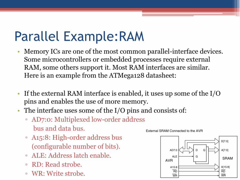
Parallel Example:RAM • Memory ICs are one of the most common parallel-interface devices.
Some microcontrollers or embedded processes require external RAM, some others support it. Most RAM interfaces are similar. Here is an example from the ATMega128 datasheet:
• If the external RAM interface is enabled, it uses up some of the I/O pins and enables the use of more memory.
• The interface uses some of the I/O pins and consists of:
▫ AD7:0: Multiplexed low-order address
bus and data bus.
▫ A15:8: High-order address bus
(configurable number of bits).
▫ ALE: Address latch enable.
▫ RD: Read strobe.
▫ WR: Write strobe.
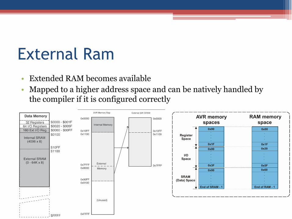
External Ram
• Extended RAM becomes available
• Mapped to a higher address space and can be natively handled by the compiler if it is configured correctly
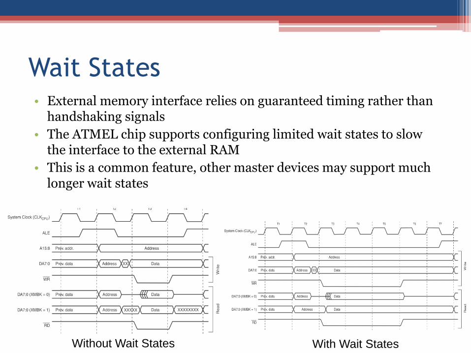
Wait States • External memory interface relies on guaranteed timing rather than
handshaking signals
• The ATMEL chip supports configuring limited wait states to slow the interface to the external RAM
• This is a common feature, other master devices may support much longer wait states
Without Wait States With Wait States
Handshaking
• In the previous interface, the microcontroller was the master and the slave device had to operate fast enough to keep up
• Other interfaces rely on handshaking allowing the slave device to send a signal back when it is ready
• Hardware interfacing uses less CPU resources and is often faster but is less flexible and vise versa
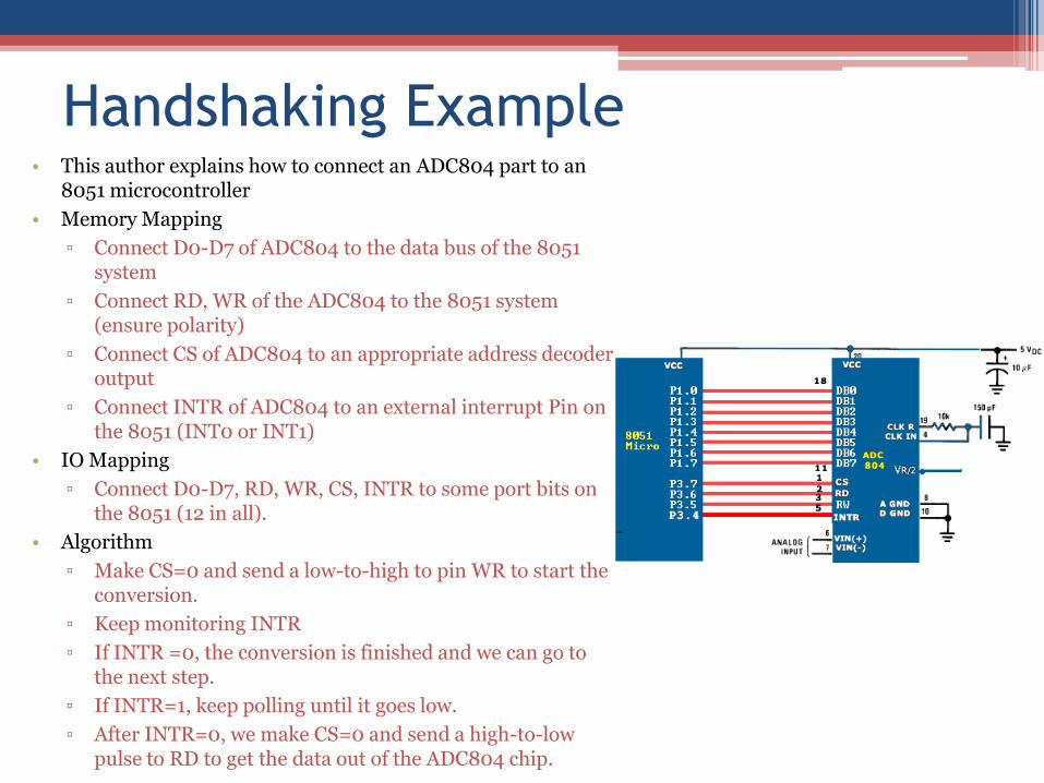
Handshaking Example • This author explains how to connect an ADC804 part to an
8051 microcontroller
• Memory Mapping
▫ Connect D0-D7 of ADC804 to the data bus of the 8051 system
▫ Connect RD, WR of the ADC804 to the 8051 system (ensure polarity)
▫ Connect CS of ADC804 to an appropriate address decoder output
▫ Connect INTR of ADC804 to an external interrupt Pin on the 8051 (INT0 or INT1)
• IO Mapping
▫ Connect D0-D7, RD, WR, CS, INTR to some port bits on the 8051 (12 in all).
• Algorithm
▫ Make CS=0 and send a low-to-high to pin WR to start the conversion.
▫ Keep monitoring INTR
▫ If INTR =0, the conversion is finished and we can go to the next step.
▫ If INTR=1, keep polling until it goes low.
▫ After INTR=0, we make CS=0 and send a high-to-low pulse to RD to get the data out of the ADC804 chip.
Design Decisions
• Things to look for in parallel hardware interfaces
▫ Does a part have a tri-state or bi-directional bus interface? How is tri-stating controlled?
Less trivial to design for these
May be necessary to include multiple parts in your design
▫ Does a part have an enable signal or Chip Select so that it can share a bus and control lines with other parts?
Useful for using multiple parts with similar interfaces
Common Serial Interfaces
• RS232 – Peer-to-peer interface (typically one is treated as master)
• RS485 – Supports communications among many devices
• USB – Master-slave interface that replaced RS232 on desktop computers (much higher speed)
• Controller Area Network – Multi-point interface that is popular in the automotive industry
Common Serial Interfaces
• Serial Peripheral Interface (SPI) – Synchronous master-Slave interface with parallel serial in/out data lines
• Inter-Integrated Circuit(I2C) – Multi-master communications with only 2 signal wires
• FireWire – High speed, typically storage or cameras. Lower communication overhead than USB
• Ethernet – High speeds and flexible but requires special hardware ICs for support and considerable software level
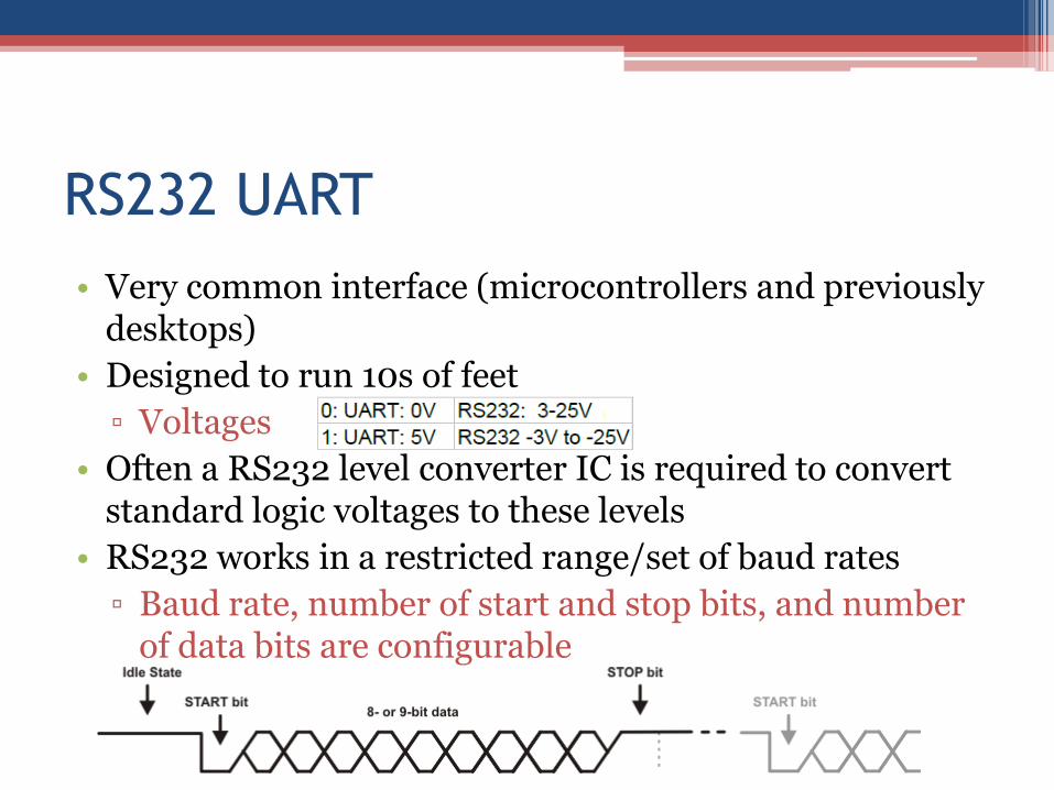
RS232 UART
• Very common interface (microcontrollers and previously desktops)
• Designed to run 10s of feet
▫ Voltages
• Often a RS232 level converter IC is required to convert standard logic voltages to these levels
• RS232 works in a restricted range/set of baud rates
▫ Baud rate, number of start and stop bits, and number of data bits are configurable
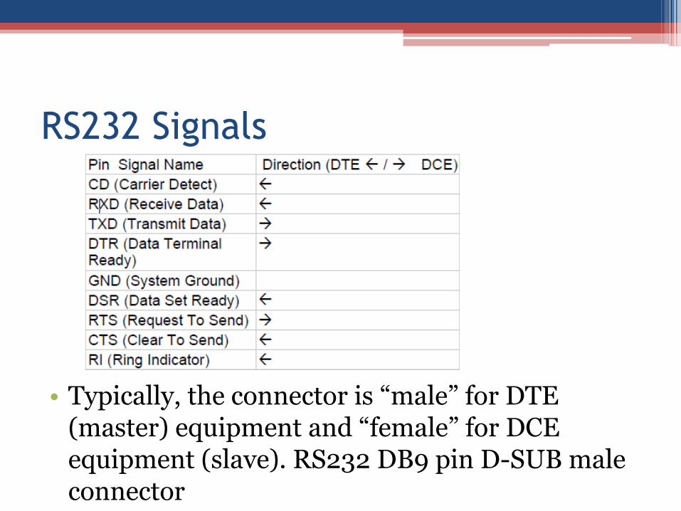
RS232 Signals
• Typically, the connector is “male” for DTE (master) equipment and “female” for DCE equipment (slave). RS232 DB9 pin D-SUB male connector
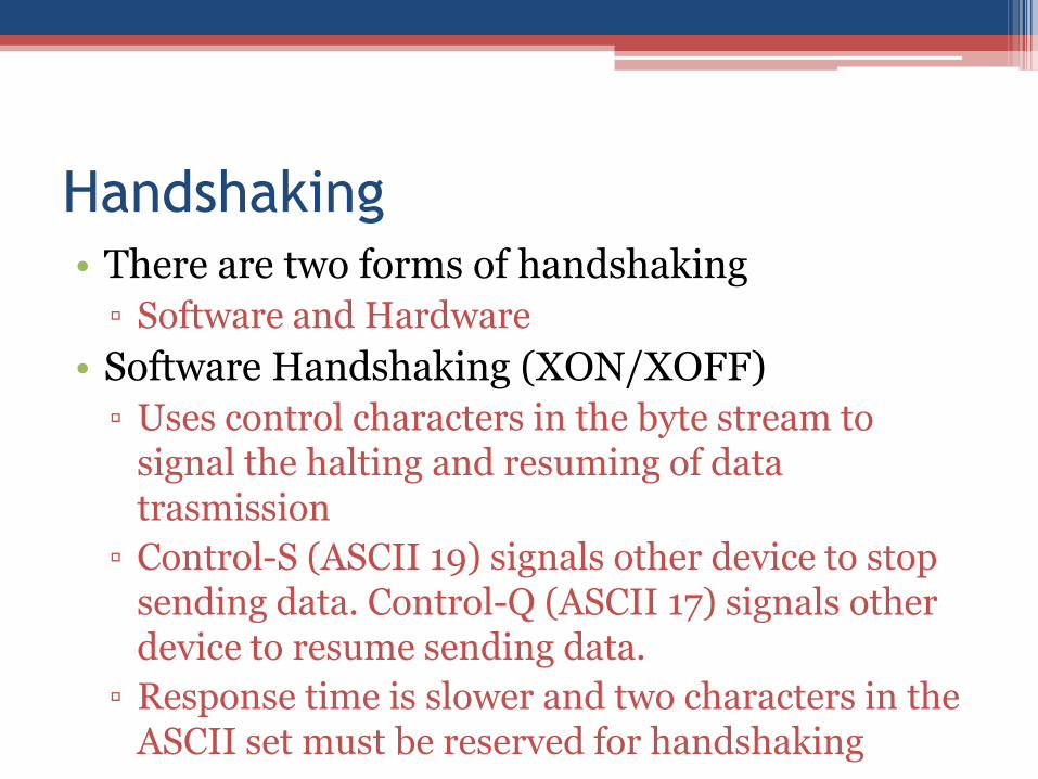
Handshaking • There are two forms of handshaking
▫ Software and Hardware
• Software Handshaking (XON/XOFF)
▫ Uses control characters in the byte stream to signal the halting and resuming of data trasmission
▫ Control-S (ASCII 19) signals other device to stop sending data. Control-Q (ASCII 17) signals other device to resume sending data.
▫ Response time is slower and two characters in the ASCII set must be reserved for handshaking
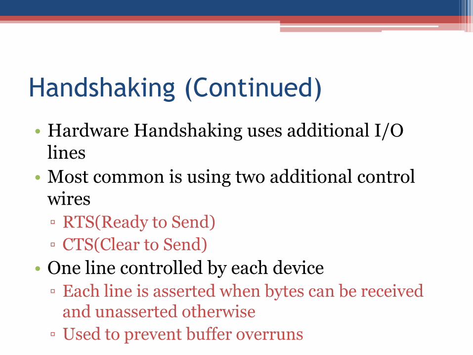
Handshaking (Continued)
• Hardware Handshaking uses additional I/O lines
• Most common is using two additional control wires
▫ RTS(Ready to Send)
▫ CTS(Clear to Send)
• One line controlled by each device
▫ Each line is asserted when bytes can be received and unasserted otherwise
▫ Used to prevent buffer overruns
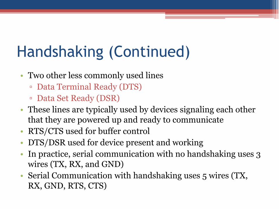
Handshaking (Continued)
• Two other less commonly used lines
▫ Data Terminal Ready (DTS)
▫ Data Set Ready (DSR)
• These lines are typically used by devices signaling each other that they are powered up and ready to communicate
• RTS/CTS used for buffer control
• DTS/DSR used for device present and working
• In practice, serial communication with no handshaking uses 3 wires (TX, RX, and GND)
• Serial Communication with handshaking uses 5 wires (TX, RX, GND, RTS, CTS)
Serial Peripheral Interface (SPI)
• Four Signals (or 3+n where n is number of devices)
▫ CLK
▫ Data In – Master In / Slave Out
▫ Data Out – Master Out / Slave In
▫ Sync – Frames data and acts as Chip Select – Cannot be shared
• This interface is commonly used for 10s of Megabits per second or faster
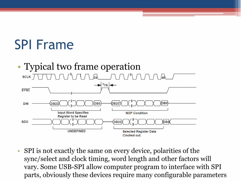
SPI Frame
• Typical two frame operation
• SPI is not exactly the same on every device, polarities of the
sync/select and clock timing, word length and other factors will vary. Some USB-SPI allow computer program to interface with SPI parts, obviously these devices require many configurable parameters
Inter-Integrated Circuit (I2C/IIC)
• Around 400Kbits/s originally, but faster versions have been defined
▫ Up to 5MHz using Ultra Fast Mode
• Intended to serve as Universal communication interface
• Only two lines
▫ SCL – Serial Clock
▫ SDA – Serial Data
▫ Uses “wired and” to allow many devices to share a line
I2C Communication Protocol One IC that wants to talk to another must:
1. Wait until it sees no activity on the I2C bus. SDA and SCL are both high. The bus is 'free'.
2. Put a message on the bus that says 'its mine' -I have STARTED to use the bus. All other ICs then LISTEN to the bus data to see whether they might be the one who will be called up (addressed).
3. Provide on the CLOCK (SCL) wire a clock signal. It will be used by all the ICs as the reference time at which each bit of DATA on the data (SDA) wire will be correct (valid) and can be used. The data on the data wire (SDA) must be valid at the time the clock wire (SCL) switches from 'low' to 'high' voltage.
4. Put out in serial form the unique binary 'address' (name) of the IC that it wants to communicate with. Addresses are 7 bits, A[7:3] serve as the category and A[2:0] serve as the identifier in the system.
5. Put a message (one bit) on the bus telling whether it wants to SEND or RECEIVE data from the other chip. (The read/write wire is gone!)
6. Ask the other IC to ACKNOWLEDGE (using one bit) that it recognized its address and is ready to communicate.
7. After the other IC acknowledges all is OK, data can be transferred.
8. The first IC sends or receives as many 8-bit words of data as it wants. After every 8-bit data word the sending IC expects the receiving IC to acknowledge the transfer is going OK.
9. When all the data is finished the first chip must free up the bus and it does that by a special message called 'STOP'. It is just one bit of information transferred by a special 'wiggling' of the SDA/SCL wires of the bus.
I2C Communication
• Masters are the devices that have the ability to initiate transfers.
• The start is signaled when the master causes the SDA line to fall while SCL is in the high state.
• The slave address follows
• Then a R/W_n bit is sent
• The slave should then acknowledge pulling the SDA line low (all data sent in I2C is acknowledged)
• ACK extension allows the receiver to hold the clock line low after an ACK to delay the sender from proceeding
• If master is writing, 8 bits are sent with the clock and on the 9th bit position the slave acknowledges
• If master is reading, the slave sends 8 bits and the master must send the acknowledge.
• After one or more send data-cycles or one or more receive cycles, the master raises the SDA line while the SCL line high unless it wishes to initiate another start to immediately communicate with another device
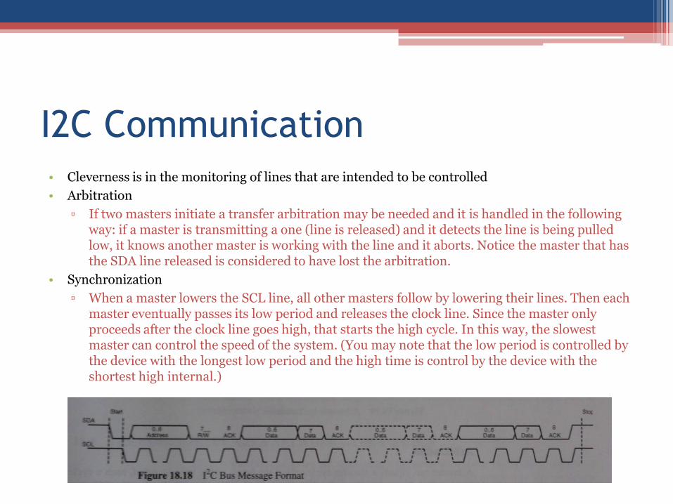
I2C Communication
• Cleverness is in the monitoring of lines that are intended to be controlled
• Arbitration
▫ If two masters initiate a transfer arbitration may be needed and it is handled in the following way: if a master is transmitting a one (line is released) and it detects the line is being pulled low, it knows another master is working with the line and it aborts. Notice the master that has the SDA line released is considered to have lost the arbitration.
• Synchronization
▫ When a master lowers the SCL line, all other masters follow by lowering their lines. Then each master eventually passes its low period and releases the clock line. Since the master only proceeds after the clock line goes high, that starts the high cycle. In this way, the slowest master can control the speed of the system. (You may note that the low period is controlled by the device with the longest low period and the high time is control by the device with the shortest high internal.)
USB Topology
• Host
▫ Only one PC host per system
▫ Provides power to peripherals
• Hub
▫ Provides ports for connecting more peripheral devices
▫ Provides power, terminations
▫ External supply or bus powered
• Device, Interfaces, and Endpoints
▫ Device is a collection of data interfaces
▫ Interface is a collection of endpoints (data channels)
▫ Endpoint associated with FIFO(s) for data I/O interfacing
• Devices are “hot pluggable”
▫ Can be plugged in with power on and systems running
• One host allows several hubs and endpoint devices
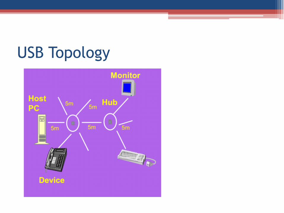
USB Topology
USB Communication
• USB assumes “guaranteed timing” and “guaranteed delivery”
▫ No packet loss detection
• Involves sending packets of synchronization, id, data, crc(cyclic redundancy check), and end of packet
• Three phases are defined
▫ Token packet phase(1) specified the communication type to take place
▫ Data(2) and handshake(3) packet phases communicate the data payloads and manage communication
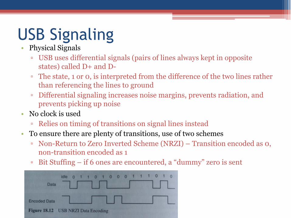
USB Signaling • Physical Signals
▫ USB uses differential signals (pairs of lines always kept in opposite states) called D+ and D-
▫ The state, 1 or 0, is interpreted from the difference of the two lines rather than referencing the lines to ground
▫ Differential signaling increases noise margins, prevents radiation, and prevents picking up noise
• No clock is used
▫ Relies on timing of transitions on signal lines instead
• To ensure there are plenty of transitions, use of two schemes
▫ Non-Return to Zero Inverted Scheme (NRZI) – Transition encoded as 0, non-transition encoded as 1
▫ Bit Stuffing – if 6 ones are encountered, a “dummy” zero is sent
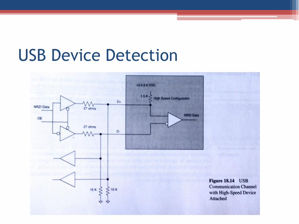
USB Device Detection
• Devices provide pullup resistors to indicate their presence. It is placed on the D+ line to indicate a 2.0 device, or on D- to indicate a low-speed device
▫ 3.0 has a separate SuperSpeed USB channel co-existing with the normal 2.0 bus
USB Device Detection
Using USB
• Several microcontrollers have built-in USB capability (arduino, etc…)
▫ Others require an external IC
• If there is a built in peripheral, template code should be provided to send data and handle data
▫ USB distinguishes between host and slave mode, one or both may be supported
• FTDI and other companies provide USB-to-Serial and USB to parallel ICs
▫ These companies often provide drivers or libraries to communicate with their devices
Summary