analysis of routing protocols for a wired network …ethesis.nitrkl.ac.in/5588/1/110cs0147-8.pdf ·...
TRANSCRIPT

ANALYSIS OF ROUTING PROTOCOLS FOR A WIRED NETWORK
Thesis submitted in partial fulfillment of the requirements for the degree of
Bachelor in Technology
In
Computer Science and Technology By
SANDEEP KUMAR SAHOO (Roll: 110CS0147)
Under the guidance of
Dr. Suchismita Chinara
Assistant Professor CSE department of NIT Rourkela
Department of Computer Science and Engineering
National Institute of Technology Rourkela Rourkela-769008, Odisha, India

Department of Computer Science and Engineering National Institute of Technology Rourkela
Rourkela-769008, Odisha, India
.
Certificate This is to certify that the work in the thesis entitled “Analysis of Routing Protocols for Wired Network” submitted by Sandeep Kumar Sahoo in partial fulfilment of the requirements for the Award of the degree of Bachelor of Technology in Computer Science and Engineering, 2010-2014 the department of Computer Science and Engineering, National Institute of Technology, Rourkela (Deemed University) is an authentic work carried out by him under my supervision and guidance. Date: Dr. S Chinara Place: NIT Rourkela Department of Computer Science & Engg. National Institute of Technology Rourkela-769008

ACKNOWLEDGEMENT
I would like to express my earnest gratitude to my thesis guide, Prof. S Chinara for believing in my ability to work on the challenging domain of networks. Her profound insights has enriched my research work. The flexibility of work she has offered me has deeply encouraged me producing the research. My heartfelt thanks to Prof. S Chinara for consistently showing me innovative research directions for the entire period of carrying out the research. I am indebted to all the professors, batch mates and friends at National Institute of Technology Rourkela for their cooperation. I would conclude with my deepest gratitude to my parents, sister and all my loved ones. My full dedication to the work would have not been possible without their blessings and moral support.
SANDEEP KUMAR SAHOO

ABSTRACT
For communication to happen, data need to be transferred from source to the destination. So router is a device which helps in forwarding packets from one network to another or from one node to another in a network. For a router to work efficiently, some protocols are implemented such as the distance vectored and link state protocols which include RIP and OSPF protocols. The work is on the analysis of the routing protocols mainly for a wired network. The work focuses on the analysis of the routing protocols in a simulator and analysis of the routing table. The work also is to design a simulator that can find the best path to a given topology. The simulator should return the routing table for each node or router in the network which would contain the best path to reach the remote destination on the metric chosen based on the routing protocol implemented. For simulating the routing protocols the simulators used are OPNET and GNS3. Both the simulators support real world simulating capabilities. The analysis of routing protocols is done on these two simulators.

LIST OF FIGURES
Figure 2.1: Application developed for simulation ------------------------12
Figure 2.2: Enter details – router details -----------------------------------13
Figure 2.3: Enter details – host details -------------------------------------14
Figure 2.4: Enter details – link details and connectivity matrix --------15
Figure 2.5: Enter details – Link bandwidth details -----------------------16
Figure 2.6: Enter details – Choose routing protocol ---------------------17
Figure 2.7: View the topology ----------------------------------------------18
Figure 4.1: OPNET Simulator – Network Domain ----------------------20
Figure 4.2: OPNET Simulator – Node Domain --------------------------21
Figure 4.3: OPNET Simulator – Process Domain -----------------------22
Figure 4.4: OPNET Simulator – Network Topology --------------------23
Figure 4.5: GNS3 Simulator – Design Mode -----------------------------25
Figure 4.6: GNS3 Simulator – Emulation Mode -------------------------26
Figure 4.7: GNS3 Simulator – Network Topology ----------------------27
Figure 5.1: New_Simulator – Routing Table for R1 using RIP --------28
Figure 5.2: New_Simulator – Routing Table for R4 using RIP --------29
Figure 5.3: New_Simulator – Routing Table for R1 using OSPF ------29
Figure 5.4: New_Simulator – Neighbor Table for R1 using OSPF ----30

Figure 5.5: OPNET Simulator – Routing Table -------------------------31
Figure 5.6: OPNET Simulator – Route Report --------------------------32
Figure 5.7: OPNET Simulator – Routing Path --------------------------32
Figure 5.8: GNS3 Simulator – Routing Table for R1 [RIP] -----------33
Figure 5.9: GNS3 Simulator – Routing Table for R4 [RIP] -----------34
Figure 5.10: GNS3 Simulator – Routing Table for R1 [OSPF] -------35
Figure 5.11: GNS3 Simulator – Neighbor and Topology
Table for R1 [OSPF] ------------------------------------------36

ABBREBIATION
RIP ROUTING INFORMATION PROTOCOL
OSPF OPEN SHORTEST PATH FIRST
EIGRP ENHANCED INTERIOR GATEWAY ROUTING PROTOCOL
IP INTERNET PROTOCOL
AD ADMINISTRATIVE DISTANCE
CPU CENTRAL PROCESSING UNIT
OPNET OPTIMIZED NETWORK ENGINEERING TOOL
GNS GRAPHICAL NETWORK SIMULATOR

CONTENTS
1 Introduction-------------------------------------------------------------------01
1.1 Problem Statement------------------------------------------------------02
2 Literature Review------------------------------------------------------------03
2.1 Routing-------------------------------------------------------------------03
2.1.1 IP Routing---------------------------------------------------------03
2.1.2 Routing Basics---------------------------------------------------04
2.1.3 Administrative Distance----------------------------------------05
2.1.4 Routing Classes--------------------------------------------------06
2.1.5 Routing Metrics--------------------------------------------------07
2.2 Routing Protocols------------------------------------------------------08
2.2.1 RIP-----------------------------------------------------------------08
2.2.2 OSPF--------------------------------------------------------------09
3 Simulator Design------------------------------------------------------------11
4 Implementation--------------------------------------------------------------18
4.1 OPNET-----------------------------------------------------------------18
4.2 GNS3-------------------------------------------------------------------23
5 Result and Analysis---------------------------------------------------------27
5.1 New_Simulator-------------------------------------------------------27
5.2 OPNET-----------------------------------------------------------------30
5.3 GNS3-------------------------------------------------------------------32
6 Conclusion--------------------------------------------------------------------36
7 Bibliography------------------------------------------------------------------37

1 | P a g e
CHAPTER – 1
INTRODUCTION
The term routing [11] refers to tacking a packet from one device and
sending it through the network to another device on a different network.
Routers don’t really care about the host, they only care about the networks
and the best path to each network. The logical network address of the
destination host is used to get packets to a network through a routes
network, and then the hardware address of the host is used to deliver the
packet from a router to the correct destination host.
A routing protocol [8] is used by routers to dynamically find all the
networks in the internetwork and to ensure that all routers have the same
routing table. Basically, a routing protocol determines the path of a packet
through an internetwork. Examples of routing protocols are RIP, OSPF,
and EIGRP. Once all the routers know about all networks, a routed
protocol can be used to send user data in the form of packets through the
established enterprise. Routed protocols are assigned to an interface and
determine the method of packet delivery. Examples of routed protocols
are IP and IPv6.
Routing protocols [8] are critical to a networks design. Dynamic routing
protocols [3] run only on routers that use them in order to discover
networks and update their routing tables. Using dynamic routing is easier
for the system administrator, than using labor intensive, manually
achieved, static routing method but it will cost in terms of router CPU
process and bandwidth in the network links. The source of the increased
bandwidth usage and CPU cycles is the operation of the dynamic routing
protocol itself. A router running a dynamic routing protocol shares routing
information with its neighboring routers, and it requires additional CPU
cycles and additional bandwidth to accomplish that.
2 | P a g e
1.1 PROBLEM STATEMENT
The objective of this project is to
Study routing protocols
Simulate the routing protocols in a simulator
Develop a simulator application which on input of a topology
would return the routing table of all the nodes in the topology

3 | P a g e
CHAPTER – 2
LITERATURE REVIEW
2.1 ROUTING
2.1.1 IP ROUTING
IP routing [11] is the process of moving packets from one network to
another network using routers. The IP routing process is important to
understand because it pertains all routers and configurations that use IP.
IP routing is used to forward packets from one node to other in the
internetwork. IP routing is also used to determine the data has to follow
to reach the destination node through the internetwork of nodes. The data
is routed in the form of packets. The packets carries the data with
informations of source and the destination addresses. IP routing enables a
router to build a forwarding table or also called as a routing table to
determine the next hop that the data packets should be sent in order to
reach the destination node.
To be able to find all the networks in the internetwork and a path to reach
each remote internetwork, a routing protocol is used. It is also used to
ensure that all the routers in the internetwork have the same routing table.
In general, a routing protocol determines the best path for a router to send
packets to the remote network through an internetwork. Some examples
of routing protocols includes Routing Information Protocol (RIP),
Routing Information Protocol version 2 (RIPv2), Enhanced Interior
Gateway Protocol (EIGRP) [3], and Open Shortest Path First (OSPF) [3].
Once after the routing table is build and all the routers has the information
needed to reach to all the remote networks in the internetwork, data
packets can be sent to the remote network using a routed protocol. A
routed protocol is to an interface. Routed protocols helps in transferring
packets from source to the destination using methods of packet delivery.
Some examples of routed protocols includes Internet Protocol (IP).

4 | P a g e
2.1.2 ROUTING BASICS
To be able to route packets from source to the destination, a router should
contain the following informations [14]: -
Destination Address
Neighbor routers from which it learns about all remote networks
Possible routes to all remote networks
The best route to each remote network
How to maintain and verify routing information
The router needs to prepare a routing table which is a map of the
interconnectivity of the nodes in the internetwork which contains details
of which path to follow and how to reach the remote network. Such a map
is built on the basis of the informations shared among the nodes in the
internetwork configured in the same routing protocol. The administrator
can also manually build the routing table.
Each and every nodes in the internetwork send and receive updates to
build up the topology. For the adjacent nodes, the node has the path to
reach it i.e. the exit interface to reach the neighbor node. If a node is not
directly connected or is connected by a sequence of nodes then the node
must find its way to the destination node. Such a node can find the
required path information either by Static Routing or by Dynamic
Routing. Static routing requires manually creation and updating of the
routing table by the administrator by inserting all network information
into each nodes. Dynamic Routing is better than Static Routing.
In the case of the Dynamic Routing, the nodes exchange details on the
basis of the routing protocol configured in the node. This information is
updated in the routing table. If any change occurs in the internetwork the
sharing process starts and the information is exchanged until all the nodes
are converged to the same routing table.

5 | P a g e
2.1.3 ADMINISTRATIVE DISTANCE
The administrative distance (AD) is used to rate the trustworthiness of
routing information. The value depends on the information that a router
receives from its neighbor routers. The Administrative Distance is a value
which ranges from 0 to 255, where 0 means it is the most trusted and 255
means that it doesn’t allows any traffic to pass through it.
If in case, a router receives more than one update from the same network,
then the router which receives such updates checks for the AD value. The
AD value for each update will differ and the router accepts only that AD
value which is the lowest and this value is updated in the routing table of
the router.
ROUTE SOURCE DEFAULT AD
A connected interface 0
A static route 1
RIP 120
EIGRP 90
OSPF 100
If a network is directly connected to a router, then that router will use the
interface connected to the network always. If any routing protocol is
configured in the router, then also the router chooses the connected
interface as default as its AD value is less. If in the router multiple routing
protocols are configured then on receiving updates from the same network
with similar routing protocols then it chooses the least AD value.
For example, if the router has a static route, a RIP route and also an OSPF
route to the same network, then the router will use the static route always
by default.

6 | P a g e
2.1.4 ROUTING CLASSES
There are three different routing classes:-
2.1.4.1 Distance Vector
The distance vector [8] routing protocols configured in the router finds the
best path to the remote network based on the distance from the router. The
distance can be measured in the form of the hop count, which basically
indicates the number of routers the data packet has to cross in order to get
to the destination router. The vector in the Distance vector indicates the
direction to the remote network. The distance vector routing protocols are
class-full routing protocols. In such classes, full routing tables are
exchanged and updates are exchanged through broadcast. e.g. - RIP, IGRP
2.1.4.2 Link State
The link state [9] routing protocols are also called as the shortest path first
protocols. The link state routing protocols consist of three routing tables,
neighbor table, topology table and the routing table. The neighbor table
contains details of the directly connected routers. The topology table
contains information about the topology of the entire internetwork. The
routing table consists of the shortest path to the remote networks. The link
state routing protocols are classless routing protocols. As compared to the
distance vector, in the link state only the missing routes are exchanged.
The updates are exchanged through multicast. e.g. – OSPF
2.1.4.3 Hybrid
The hybrid [8] protocols use the aspects of both the distance vector and the
link state routing protocols. The hybrid protocols are classless routing
protocols. In the case of hybrid protocols, only the missing routes are
exchanged between the routers and the updates are exchanged through
multicast. e.g. – EIGRP

7 | P a g e
2.1.5 ROUTING METRICS
The different routing metrics [10] includes the following: -
1. Hop count
The number of routers which a packet will pass before arriving at
the destination router.
2. Cost
It is generally an arbitrary value that is assigned by the administrator
and is based on the bandwidth
3. Bandwidth
It is the data capacity of the link.
4. Delay
It measures the total time taken by a packet to move from the source
router to the destination router.
5. Load
It measures the amount of activity on a network source link a router
or a link.
6. Reliability
It refers to the network link’s bit error rate.
7. MTU
It stands for Maximum Transmission Unit. It resembles the
maximum frame length in octets which is allowed to pass to the
internetwork without fragmentation.

8 | P a g e
2.2 ROUTING PROTOCOLS
2.2.1 RIP [ROUTING INFORMATION PROTOCOL]
RIP [4] is an open standard routing protocol. It is a distance vectored
routing protocols. It is a class-full routing protocol where updates are
exchanged through broadcast. The routing table is exchanged every 30
seconds among the routers in the inter-network. The RIP protocol uses
hop count as the metric to find the shortest path but the maximum
allowable hop count is 15 by default. The RIP protocols is used only for
a small network and is ineffective for a large network. The Administrative
Distance of RIP is 120.
2.2.1.1 RIP TIMERS
To manage the routing performance, RIP uses four different kinds of
timers:
Update timer
It is the time interval after which a router sends it’s a copy of the
routing table as update to the neighbor routers. The update timer is
30 sec by default.
Invalid timer
It is the time interval after which a router understands that the path
to a network is invalid or becomes invalid. The invalid timer is 180
sec by default.
Hold-down timer
It specifies the amount of time for which the information about the
poorer routes are ignored. The hold-down timer is 180sec by default.

9 | P a g e
Flush timer
It is the time before the invalid route is purged from the routing
table. The flush timer is 240 sec by default.
2.2.1.2 Dis-advantages of RIP
It uses more bandwidth as updates are exchanged every 30 seconds
where each update contains the complete routing table of the router.
It does not uses bandwidth as the metric for calculation of the
shortest path.
RIP has a very slow convergence.
RIP implementation can lead to routing loops in the network.
RIP is only applicable to small network and is inefficient for larger
networks.
2.2.2 OSPF [OPEN SHORTEST PATH FIRST]
Open Shortest Path First [4] is an open standard routing protocol. It is the
successor of RIP routing protocol. It is a classless routing protocol. It
works with link state advertisement and uses Dijkstra algorithm to find
the shortest path. Here updates are exchanged through multicast i.e.
224.0.0.5. The administrative distance is 110 and the metric used by OSPF
is the cost which is based on the bandwidth of the link. The cost is found
by dividing the bandwidth in bps to 10^8.
10 | P a g e
2.2.2.1 FEATURES: -
Includes division into areas and autonomous systems.
It minimizes the traffic by reducing update.
It is scalable.
It supports Variable Length Subnet Mask and Classless Inter-
Domain Routing.
Has maximum hop count of 255.
It can be configured on different vendor routers.
Faster convergence.
Hello packets are sent every 10sec.
Hierarchical design with multiple areas.
2.2.2.2 OSPF TABLES
The OSPF routing protocol has three tables: -
Neighbor table
The neighbor table has the details about the nodes in the topology
that are directly connected to the router i.e. the adjacent nodes.
Database table
The database table has the details of the topology of the network i.e.
how each node is connected to other nodes.
Routing table
The routing table has the best path to reach each network in the
internetwork on the basis of the protocol implemented in the router.
2.2.2.3 Dis-advantages of OSPF
It consumes more memory.
It consumes a lot of processing power.

11 | P a g e
CHAPTER – 3
SIMULATOR DESIGN
The propose task is to design a simulator application which on input of a
topology would return the routing table of all the nodes in the topology.
To be able to run the application, the topology has to be uploaded to the
application and then simulated to provide output as routing tables.
Figure 2.1: Application developed for simulation
For this, the input file contains details that need to be filled up in a
sequential manner as follows: -

12 | P a g e
STEP 1: - [ROUTER DETAILS]
Here, the total number of routers to be in the network is provided.
On giving the total number of nodes/routers for a network, the
simulator generates the default values of each router.
o The default value contains information like Router ID
o Router Name
o Router Status
o No of hosts connected
o Router IP
o No of serial ports
The user can change the default values to the user defined values
and can save to it.
The user defined values need to be saved before going to the next
step.
Figure 2.2: Enter details – router details

13 | P a g e
STEP 2: - [HOST DETAILS]
Host details contains details about each hosts created for each and
every router.
It contains default values like
o Connected to router ID
o Host ID
o Host Name
o Status
o Host IP
Based on user requirements, details can be changed and every
changes made has to be saved to move to further steps.
Figure 2.3: Enter details – host details

14 | P a g e
STEP 3: - [LINK DETAILS]
It contains two steps-
o Connectivity
o Bandwidth
Connectivity
o Here the user has to enter the topology i.e. how each router is
connected to the other router
o Connection is entered in the form of a matrix
Red - no connection
Green - connection
o By default, it is red i.e. no connection. On a single click, the
red change to green and a connection is established between
the respected nodes.
Figure 2.4: Enter details – link details and connectivity matrix

15 | P a g e
Bandwidth
o For a serial port, three different bandwidth values has been
used and a user can assign any one of these three values to a
link between the nodes.
o By default, the link has a bandwidth of 64 kbps provided a
connection exists.
o The three different bandwidths: -
64 kbps
1544 kbps or 1.5 Mbps
2000 kbps or 2 Mbps
o On successive click events different bandwidths can be
assigned to the links.
Figure 2.5: Enter details – Link bandwidth details

16 | P a g e
STEP 4: - [PROTOCOL CHOOSE]
Here, the routing protocol is chosen: -
o RIP
o OSPF
Figure 2.6: Enter details – Choose routing protocol

17 | P a g e
STEP 5: - [PLOT TOPOLOGY]
The topology is created as a graphical representation: -
Figure 2.7: View the topology

18 | P a g e
CHAPTER – 4
IMPLEMENTATION
In this thesis, two platforms have been chosen to simulate two routing
protocols. The two chosen simulators are GNS3 and OPNET. These two
simulators are very helpful in simulating the real world scenario and can
be used to debugging the real world network problems.
4.1 OPNET
OPNET [13] is a powerful software used to simulate heterogeneous
network with various protocols. OPNET is a simulator built on top of
discrete event system (DES) and it simulates behavior by modeling each
event in the system and processes it through user defined processes. It
allows hierarchical model. OPNET provides a comprehensive
development environment to support the modelling system that can be
analyzed by performing DES. In this thesis, the network simulator
optimized network Engineering Tools (OPNET) modeler has been used
as a simulation environment.
4.1.1 STRUCTURE OF OPNET
OPNET is built with huge number of library functions using C and C++
code. OPNET has a high end graphical interface. It also includes
functionality of real time simulation graph plotting.

19 | P a g e
4.1.2 HIERARCHICAL STRUCTURE
The hierarchical structure [13] of OPNET model consists of three models:-
4.1.2.1 Network Domain
The network domain consists of the physical interconnection and the
configuration of the different nodes included in the topology of the
internetwork. It represents the complete structure of the topology on a map
to be simulated.
Figure 4.1: OPNET Simulator – Network Domain

20 | P a g e
4.1.2.2 Node Domain
The Node Domain of the network domain consists of the internal
infrastructure of the internetwork. The nodes can be routers, workstations,
satellite and so on.
Figure 4.2: OPNET Simulator – Node Domain
4.1.2.3 Process Domain
Process Domain are used to specify the attribute of the processor and
square model by using source code C and C++ which is inside the node
models.

21 | P a g e
Figure 4.3: OPNET Simulator – Process Domain
4.1.3 SIMULATION STUDY
The protocols used in the thesis are RIP and OSPF. These two protocols
are used to find the best path for a packet to travel from source to the
destination. In the simulator OPNET, we simulate these two protocols for
a particular topology and find the routing table for the network. The
routing table gives the shortest path to reach the destination on the basis
of the protocol implemented and the metric that the routing protocol uses.

22 | P a g e
4.1.4 NETWORK TOPOLOGY
The topology used in consists of the routers and different networks
connected to each other. The topology contains four router connected to
different networks.
Figure 4.4: OPNET Simulator – Network Topology
4.1.5 PROTOCOL SCENARIO
The topology of the network for the simulation of the two routing
protocols i.e. RIP and OSPF consists of 5 nodes where each node
represents to be the gateway node to a different network. The five
different nodes are connected to each other in a manner as shown in the
diagram.

23 | P a g e
4.2 GNS3
GNS3 [12] is an open source software that helps simulate the complex
networks as close as possible to the way real networks perform and such
is achieved without having dedicated network hardware such as routers
and switches.
This software provides an intuitive graphical user interface to design and
configure virtual networks, it runs on traditional PC hardware and may be
used on multiple operating systems, including Windows, Linux, and
MacOS X.
In order to provide a complete and an accurate simulations, the GNS3
actually uses the following emulators to run the very same operating
systems as in real networks:
Dynamips, the well-known Cisco IOS emulator.
VirtualBox, runs desktop and server operating systems as well as
Juniper JunOS.
Qemu, a generic open source machine emulator, it runs Cisco ASA,
PIX and IPS.
4.2.1 MODES IN GNS3
There are two modes [12] of working in the GNS3 simulator: -
4.2.1.1 Design mode
By default, GNS3 starts in design mode. In this mode, one can create a
topology design in graphical manner. To do one must drag a specific node
from the left where there is list of other networking device and drop in the
design area and then connect the different devices to form a topology.

24 | P a g e
Figure 4.5: GNS3 Simulator – Design Mode
4.2.1.2 Emulation mode
After one has designed the topology, one can switch over to the next mode
by selecting the Emulation mode in the menu bar. On selecting the
Emulation mode, all the setting saved or configured in each nodes will be
visible in the design area of the simulator. One can start, stop or suspend
an IOS instance by right clicking on a node. After connecting with the
console to the routers, we can assign IP addresses to the serial interfaces.

25 | P a g e
Figure 4.6: GNS3 Simulator – Emulation Mode
4.2.2 NETWORK TOPOLOGY SCENARIO
The topology of the network for the simulation of the two routing
protocols i.e. RIP and OSPF consists of 5 nodes where each node
represents to be the gateway node to a different network. The five
different nodes are connected to each other in a manner as shown in the
diagram.

26 | P a g e
Figure 4.7: GNS3 Simulator – Network Topology
4.2.3 PROTOCOL SCENARIO
On the topology selected and routers are configured to be connected to
others and the interfaces are configured. After such step, protocol is
configured. On the basis of the protocol chosen for implementation the
path varies and the routing table varies. The routing table for the routers
for different protocol implementation is give in details in the result and
analysis section

27 | P a g e
CHAPTER – 5
RESULT AND ANALYSIS
This section of the thesis shows the results and analysis that have been
concluded from the implementation of the routing protocols in the
network based simulators. The result mainly deals with the analysis of the
routing table of the routers in the internetwork. The analysis of the results
for each simulator on which the routing protocols has been implemented
are: -
5.1 New_Simulator (designed and developed for the thesis)
The topology used in the analysis of the routing table consists of five
routers connected in the form of a circle. The routers are connected to
each other by serial ports. The serial ports are the ports through which one
router is connected to another router. In this simulator, two routing
protocols has been implemented. Among the two routing protocols, one
is RIP and the other is OSPF. The result which includes the routing table
of each routers for each protocol implemented are given as follows: -
5.1.1 PROTOCOL --- RIP
The routing table for router R1 is
Figure 5.1: New_Simulator – Routing Table for R1 using RIP

28 | P a g e
The routing table for R4 is
Figure 5.2: New_Simulator – Routing Table for R4 using RIP
The routing table displays the details of all the five networks and the
minimum hop count to reach the network and the exit interface of the
router including the connection type. The connection type, R indicates
RIP connection and C indicates directly connected networks respectively.
5.1.2 PROTOCOL --- OSPF
The routing table for router R1 is
Figure 5.3: New_Simulator – Routing Table for R1 using OSPF

29 | P a g e
The routing table gives the details of the routing table for the router R1
which contains details of how to reach to the destination. The details
included are the networks ip address, the exit interface of the router, cost
to reach the network and the connection type. The connection type, O
indicates OSPF protocol implementation. The cost is calculated by
dividing 10^8 by the bandwidth in bps. The minimum cost to the
particular network find it place in the routing table.
The neighbor table of the router R1 is
Figure 5.4: New_Simulator – Neighbor Table for R1 using OSPF
The neighbor table contains details of the router which are directly
connected to the host router and it also gives the exit interface of the host
router to reach the destination router. As router R1 is directly connected
to router R2 and R5, so the neighbor table consists of two inputs i.e. the
router R2 and the router R5 and it also includes information about the exit
interface to reach the destination router.

30 | P a g e
5.2 OPNET
The OPNET simulator is used to find the routing table and also show the
path followed by the packet through the topology to reach the destination
router. It gives a graphical representation of the shortest path as per the
protocol implemented in the router.
5.2.1 PROTOCOL --- RIP
The routing table provides details for the path to be followed to reach the
destination router in the best possible shortest path available.it includes
details like the destination network address, subnet mask, next hop ip
address, exit interface name, metric and the protocol used.
Figure 5.5: OPNET Simulator – Routing Table

31 | P a g e
52.2 PROTOCOL --- OSPF
In case of OSPF routing protocol in OPNET, we provide details to find
the shortest path from router A to router C, and the path found is Router
A to router D to router E and at last to router C.
Figure 5.6: OPNET Simulator – Route Report
The path is displayed as in the following diagram:
Figure 5.7: OPNET Simulator – Routing Path

32 | P a g e
5.3 GNS3
The topology used in the analysis of the routing table consists of five
routers connected in the form of a circle. The routers are connected to
each other by serial ports. The serial ports are the ports through which one
router is connected to another router. In this simulator, two routing
protocols has been implemented. Among the two routing protocols, one
is RIP and the other is OSPF. The result which includes the routing table
of each routers for each protocol implemented are given as follows: -
5.3.1 PROTOCOL --- RIP
The routing table for the router R1 and the router R4 are given below
Figure 5.8: GNS3 Simulator – Routing Table for R1 [RIP]
33 | P a g e
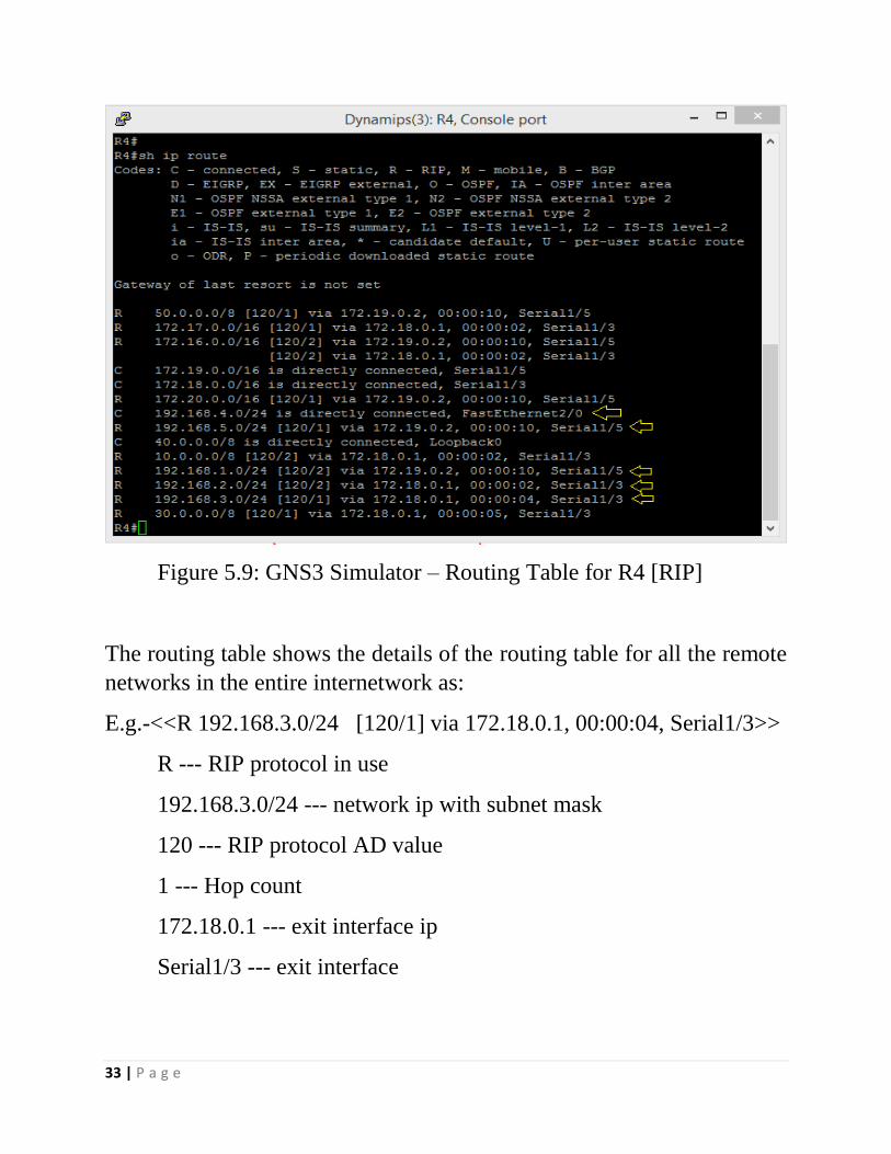
Figure 5.9: GNS3 Simulator – Routing Table for R4 [RIP]
The routing table shows the details of the routing table for all the remote
networks in the entire internetwork as:
E.g.-<<R 192.168.3.0/24 [120/1] via 172.18.0.1, 00:00:04, Serial1/3>>
R --- RIP protocol in use
192.168.3.0/24 --- network ip with subnet mask
120 --- RIP protocol AD value
1 --- Hop count
172.18.0.1 --- exit interface ip
Serial1/3 --- exit interface

34 | P a g e
5.3.2 PROTOCOL --- OSPF
The routing table for router R1 is
Figure 5.10: GNS3 Simulator – Routing Table for R1 [OSPF]

35 | P a g e
The neighbor and the topology table for router R4 are: -
Figure 5.11: GNS3 Simulator – Neighbor and Topology table for R1
[OSPF]
The neighbor table show only two entries as the router R4 is directly
connected to only two routers and it also displays their ip address and the
exit interface to reach the router.
The database /topology table contains details of the routers in the topology
including their age, sequence number, checksum value and link count.

36 | P a g e
CHAPTER – 6
CONCLUSION
The analysis of the routing protocols has been done in a detailed way in
two of the most advanced simulators i.e. GNS3 and OPNET. These two
simulators can help in simulating the real world scenario which helps in
determining flaws in the network and can also help in creating a network
before implementing in the real world. Such use of simulators can help
the network administrator in a large way to reduce to the future work load.
The routing protocols that has been used in this thesis are RIP and OSPF.
In this thesis for a better comparison to happen one protocol from distance
vector and one protocol from link state has been used. Using these
protocols helps in finding the best possible shortest path from the
available paths from the source router to the destination router. The source
router send update messages to its neighbor routers and receives update
messages from other routers and by using the respective algorithm of the
protocol implemented in the router, it calculates the best path to reach the
remote network. This thesis result gives the routing table comparison of
different routers in the network. This thesis is the result of the thorough
understanding of the use of the two simulators and the routing protocols
without which it would not have been possible to complete the thesis.
37 | P a g e
CHAPTER - 7
BIBLOGRAPHY
1. Shen Yang, Dai Hao; Qi Qang-dong “Performance comparisons between
OSPF and EIGRP in tactical IP networks” (Inst. of Command Autom, PLA
Univ. of Sci. & Tech. Nanjing, China); Source: Journal of PLA University of
Science and Technology (Natural Science Edition), v 6, n 3, p2 41-5, June
2000
2. Garcia-Luna-Aceves, J, J.; Zaumen, W.T “Area-based loop-free internet
routing” Source: Proceedings IEEE INFOCOM 94. The Conference on
Computer Communications. Networking for Global Communications (Cat.
No. 94CH3401-7), 1000-8 vol.3,1994
3. Kisten, S. Ping-Tsai Chung. ”Analysis and experimentation on dynamic
routing protocols: EIGRP and OSPF”(Dept. of Computer Science, Long
Island Univ., Brooklyn, NY, USA); Source: International Conference on
Internet Computing - IC'03, p 591-3 Vol.2, 2003
4. Thorenoor, S.G.”Dynamic Routing Protocol Implementation Decision
between EIGRP, OSPF and RIP Based on Technical Background Using
OPNET Modeler” (Wipro Technol.,Bangalore, India) Source: Proceedings of
the 2010 Second International Conference on Computer and Network
Technology (ICCNT 2010), p 191-5, 2010
5. Yee, J.R.”On the International routing protocol enhanced interior gateway
routing protocols: is it optimal?” (Dept. of Electr. Eng.,Hawaii Univ.,
Honolulu, HI, USA) Source: International Transactions in Operational
Research, v 13, n 3, p 177-94, May 2006
6. Nohl, A.R, Molnar, G “The convergence of the OSPF routing protocol”
(Ericsson Res., Ericsson Hungary Ltd., Budapest, Hungary). Source:
Periodica Polytechnica Electrical Engineering, v 47, n 1-2, p 89-100, 2002
7. Talal Mohamed Jaffar, “Simulation-Based Routing Protocols Analysis
(Thesis)” Ph.D. Dept. Elect. Eng., Georgia Institute of Technology, 2007

38 | P a g e
8. Rick Graziani and Allan Jonson, “Routing protocols and concepts: CCNA
exploration companion guide” Pearson Education. London, 2008.
9. Todd Lammle, “Cisco Certified Network Associate” 5th edition, 2005
10. Cisco, “Internet Technology Handbook” http://www.cisco.com/en/US/docs/
internetworking/technology/handbook/Enhanced_IGRP.html
11. Cisco, “IP Routing, Introduction to EIGRP” Document ID: 13669.
http://www.cisco.com/en/US/tech/tk365/technology_tech_note09186a00800
93f07.shtml#hw Ravi Malhotra, “IP Routing" 0-596-00275-0” January 2002.
http://oreilly.com/catalog/iprouting/chapter/ch04.html#45434
12. GNS3 simulator, “official website”, http://www.gns3.net
13. Introduction to OPNET Simulator” http://bolero.ics.uci.edu/
ypan/OPNET/Introduction %20 to %20OPNET%20 simulator.pdf
14. Todd Lammle, “Network+ study guide” Pearson Education. London, 2008.