windsonic ultrasonic wind sensor - campbell sci · precautions danger — many hazards are...
TRANSCRIPT

WindSonic Ultrasonic Wind Sensor
Issued: 30.11.15
Copyright © 2004-2015 Campbell Scientific, Inc.
Printed under licence by Campbell Scientific Ltd.
CSL 524
US
ER
GU
IDE


Guarantee
This equipment is guaranteed against defects in materials and workmanship.
We will repair or replace products which prove to be defective during the
guarantee period as detailed on your invoice, provided they are returned to us
prepaid. The guarantee will not apply to:
Equipment which has been modified or altered in any way without the
written permission of Campbell Scientific
Batteries
Any product which has been subjected to misuse, neglect, acts of God or
damage in transit.
Campbell Scientific will return guaranteed equipment by surface carrier
prepaid. Campbell Scientific will not reimburse the claimant for costs incurred
in removing and/or reinstalling equipment. This guarantee and the Company’s
obligation thereunder is in lieu of all other guarantees, expressed or implied,
including those of suitability and fitness for a particular purpose. Campbell
Scientific is not liable for consequential damage.
Please inform us before returning equipment and obtain a Repair Reference
Number whether the repair is under guarantee or not. Please state the faults as
clearly as possible, and if the product is out of the guarantee period it should
be accompanied by a purchase order. Quotations for repairs can be given on
request. It is the policy of Campbell Scientific to protect the health of its
employees and provide a safe working environment, in support of this policy a
“Declaration of Hazardous Material and Decontamination” form will be
issued for completion.
When returning equipment, the Repair Reference Number must be clearly
marked on the outside of the package. Complete the “Declaration of
Hazardous Material and Decontamination” form and ensure a completed copy
is returned with your goods. Please note your Repair may not be processed if
you do not include a copy of this form and Campbell Scientific Ltd reserves
the right to return goods at the customers’ expense.
Note that goods sent air freight are subject to Customs clearance fees which
Campbell Scientific will charge to customers. In many cases, these charges are
greater than the cost of the repair.
Campbell Scientific Ltd,
80 Hathern Road,
Shepshed, Loughborough, LE12 9GX, UK
Tel: +44 (0) 1509 601141
Fax: +44 (0) 1509 601091
Email: [email protected]
www.campbellsci.co.uk


PLEASE READ FIRST About this manual
Some useful conversion factors:
Area: 1 in2 (square inch) = 645 mm2 Length: 1 in. (inch) = 25.4 mm 1 ft (foot) = 304.8 mm 1 yard = 0.914 m 1 mile = 1.609 km
Mass: 1 oz. (ounce) = 28.35 g 1 lb (pound weight) = 0.454 kg Pressure: 1 psi (lb/in2) = 68.95 mb Volume: 1 UK pint = 568.3 ml 1 UK gallon = 4.546 litres 1 US gallon = 3.785 litres
Recycling information At the end of this product’s life it should not be put in commercial or domestic refuse but sent for recycling. Any batteries contained within the product or used during the products life should be removed from the product and also be sent to an appropriate recycling facility.
Campbell Scientific Ltd can advise on the recycling of the equipment and in some cases arrange collection and the correct disposal of it, although charges may apply for some items or territories.
For further advice or support, please contact Campbell Scientific Ltd, or your local agent.
Campbell Scientific Ltd, Campbell Park, 80 Hathern Road, Shepshed, Loughborough, LE12 9GX, UK Tel: +44 (0) 1509 601141 Fax: +44 (0) 1509 601091
Email: [email protected] www.campbellsci.co.uk


Precautions DANGER — MANY HAZARDS ARE ASSOCIATED WITH INSTALLING, USING, MAINTAINING, AND WORKING ON OR AROUND TRIPODS, TOWERS, AND ANY ATTACHMENTS TO TRIPODS AND TOWERS SUCH AS SENSORS, CROSSARMS, ENCLOSURES, ANTENNAS, ETC. FAILURE TO PROPERLY AND COMPLETELY ASSEMBLE, INSTALL, OPERATE, USE, AND MAINTAIN TRIPODS, TOWERS, AND ATTACHMENTS, AND FAILURE TO HEED WARNINGS, INCREASES THE RISK OF DEATH, ACCIDENT, SERIOUS INJURY, PROPERTY DAMAGE, AND PRODUCT FAILURE. TAKE ALL REASONABLE PRECAUTIONS TO AVOID THESE HAZARDS. CHECK WITH YOUR ORGANIZATION'S SAFETY COORDINATOR (OR POLICY) FOR PROCEDURES AND REQUIRED PROTECTIVE EQUIPMENT PRIOR TO PERFORMING ANY WORK.
Use tripods, towers, and attachments to tripods and towers only for purposes for which they are designed. Do not exceed design limits. Be familiar and comply with all instructions provided in product manuals. Manuals are available at www.campbellsci.eu or by telephoning +44(0) 1509 828 888 (UK). You are responsible for conformance with governing codes and regulations, including safety regulations, and the integrity and location of structures or land to which towers, tripods, and any attachments are attached. Installation sites should be evaluated and approved by a qualified engineer. If questions or concerns arise regarding installation, use, or maintenance of tripods, towers, attachments, or electrical connections, consult with a licensed and qualified engineer or electrician.
General • Prior to performing site or installation work, obtain required approvals and permits. Comply with all
governing structure-height regulations, such as those of the FAA in the USA. • Use only qualified personnel for installation, use, and maintenance of tripods and towers, and any
attachments to tripods and towers. The use of licensed and qualified contractors is highly recommended. • Read all applicable instructions carefully and understand procedures thoroughly before beginning work. • Wear a hardhat and eye protection, and take other appropriate safety precautions while working on or
around tripods and towers. • Do not climb tripods or towers at any time, and prohibit climbing by other persons. Take reasonable
precautions to secure tripod and tower sites from trespassers. • Use only manufacturer recommended parts, materials, and tools.
Utility and Electrical • You can be killed or sustain serious bodily injury if the tripod, tower, or attachments you are installing,
constructing, using, or maintaining, or a tool, stake, or anchor, come in contact with overhead or underground utility lines.
• Maintain a distance of at least one-and-one-half times structure height, or 20 feet, or the distance required by applicable law, whichever is greater, between overhead utility lines and the structure (tripod, tower, attachments, or tools).
• Prior to performing site or installation work, inform all utility companies and have all underground utilities marked.
• Comply with all electrical codes. Electrical equipment and related grounding devices should be installed by a licensed and qualified electrician.
Elevated Work and Weather • Exercise extreme caution when performing elevated work. • Use appropriate equipment and safety practices. • During installation and maintenance, keep tower and tripod sites clear of un-trained or non-essential
personnel. Take precautions to prevent elevated tools and objects from dropping. • Do not perform any work in inclement weather, including wind, rain, snow, lightning, etc.
Maintenance • Periodically (at least yearly) check for wear and damage, including corrosion, stress cracks, frayed cables,
loose cable clamps, cable tightness, etc. and take necessary corrective actions. • Periodically (at least yearly) check electrical ground connections.
WHILE EVERY ATTEMPT IS MADE TO EMBODY THE HIGHEST DEGREE OF SAFETY IN ALL CAMPBELL SCIENTIFIC PRODUCTS, THE CUSTOMER ASSUMES ALL RISK FROM ANY INJURY RESULTING FROM IMPROPER INSTALLATION, USE, OR MAINTENANCE OF TRIPODS, TOWERS, OR ATTACHMENTS TO TRIPODS AND TOWERS SUCH AS SENSORS, CROSSARMS, ENCLOSURES, ANTENNAS, ETC.


i
Contents
PDF viewers: These page numbers refer to the printed version of this document. Use the
PDF reader bookmarks tab for links to specific sections.
1. Introduction ................................................................ 1
2. Cautionary Statements .............................................. 1
3. Initial Inspection ........................................................ 2
3.1 Ships With ............................................................................................ 2
4. Quickstart ................................................................... 2
4.1 WindSonic1 Short Cut Tutorial ........................................................... 2 4.2 WindSonic4 Short Cut Tutorial ........................................................... 5
5. Overview ..................................................................... 7
6. Specifications ............................................................ 8
6.1 Wind Direction ..................................................................................... 8 6.2 Wind Speed .......................................................................................... 8 6.3 General Specifications ......................................................................... 8 6.4 Campbell Scientific Factory Default Settings for the WindSonic1 ...... 9
7. Installation ................................................................ 10
7.1 Siting .................................................................................................. 10 7.2 Mount the Sensor ............................................................................... 10 7.3 Wiring ................................................................................................ 11
7.3.1 Datalogger to WindSonic1 Wiring ............................................. 11 7.3.2 SDM-SIO1 Wiring ...................................................................... 12 7.3.3 WindSonic4 Wiring .................................................................... 12
7.4 Datalogger Programming ................................................................... 13 7.4.1 WindSonic1 Programming .......................................................... 13
7.5 WindSonic4 Programming ................................................................. 14
8. Operation .................................................................. 15
8.1 Sensor Configuration ......................................................................... 15 8.2 SDI-12 Measurement Details ............................................................. 15
8.2.1 Changing the SDI-12 Address Using LoggerNet and a Datalogger16 8.2.1.1 CR200(X)-series Datalogger ............................................ 16
9. Maintenance and Troubleshooting ......................... 17
9.1 Troubleshooting ................................................................................. 17 9.2 Maintenance ....................................................................................... 18
10. Siting References .................................................... 18
Appendix A. Importing Short Cut Code ................... A-1

ii
Appendix B. Example Programs .............................. B-1
B.1 WindSonic1 Programs ..................................................................... B-1 B.1.1 CR1000 WindSonic1 Program Using COMn Port ................... B-1 B.1.1 CR1000 WindSonic1 Program Using SDM-SIO1 .................... B-2
B.2 WindSonic4 Programs ..................................................................... B-3 B.2.1 CR200X WindSonic4 Program................................................. B-3 B.2.2 CR800 WindSonic4 Program ................................................... B-4
Appendix C. WindSonic Orientation ........................ C-1
Appendix D. Updating an Older Program for Measuring a WindSonic1 with the New Settings ................. D-1
Appendix E. Using the CR6 Datalogger’s CPI/RS-232 Port .............................................................. E-1
Figures
6-1. White dot indicating that the WindSonic1 has the newer settings ..... 10 7-1. WindSonic1 ....................................................................................... 11 8-1. SDI-12 Transparent Mode for a CR200(X) used to change the
SDI-12 address from 0 to 1............................................................. 17
C-1. Magnetic Declination at 2012.5 (degrees relative to true north,
positive is east) ............................................................................. C-2
C-2. Declination Angles East of True North Are Subtracted From 0
to Get True North ......................................................................... C-2 C-3. Declination Angles West of True North Are Added to 0 to Get
True North .................................................................................... C-3
C-4. NOAA Web Calculator ……………………………………………C-3
Tables
7-1. WindSonic1 to Datalogger Connections ............................................ 12 7-2. WindSonic1 to SDM-SIO1 Connections ........................................... 12 7-3. WindSonic4 to Datalogger Connections ............................................ 13 7-4. CRBasic Datalogger Operating Systems that Support RS-232
Communications and SerialInRecord() .......................................... 14 7-5. WindSonic4 Data Format Option....................................................... 14 7-6. Datalogger Operating Systems that Support the SDI-12 “aRo!”
Command ....................................................................................... 15 8-1. WindSonic1 Output Frequencies ....................................................... 15 9-1. Gill WindSonic Diagnostic Codes ..................................................... 18 9-2. Example Datalogger Program Diagnostic Codes ............................... 18 B-1. Wiring for CR1000 Example Program ............................................. B-1 B-2. Wiring for CR1000/SDM-SIO1 Program Example ......................... B-2 B-3. Wiring for CR200(X) Program Example ......................................... B-3 B-4. Wiring for CR800 Program Example .............................................. B-4 E-1. CPI/RS-232 Connections ................................................................. E-1

1
WindSonic Ultrasonic Wind Sensor
1. Introduction The WindSonic1 and WindSonic4 are two-dimensional ultrasonic anemometers for
measuring wind speed and wind direction. They provide an alternative to traditional
mechanical cup and vane or propeller and vane anemometers. Unlike mechanical
anemometers, there are no moving parts to be periodically replaced—minimizing
routine maintenance costs. These two-dimensional anemometers are manufactured
by Gill Instruments, Ltd.
The WindSonic1 and WindSonic4 differ in their output signal. The WindSonic1
outputs an RS-232 signal that can be read by the CR6, CR800, CR850, CR1000, or
CR3000 dataloggers. The WindSonic4 outputs an SDI-12 signal that can be read by
the CR200(X)-series, CR6, CR800, CR850, CR1000, CR3000, or CR5000
dataloggers.
This manual provides information only for CRBasic dataloggers. It
is also compatible with our retired Edlog dataloggers. For Edlog
datalogger support, see an older manual at
www.campbellsci.com/old-manuals or contact a Campbell Scientific
application engineer for assistance.
2. Cautionary Statements READ AND UNDERSTAND the Precautions section at the front of this
manual.
The WindSonic is a precision instrument. Please handle it with care.
If the WindSonic is to be installed at heights over 2 m (6 ft), be familiar with
tower safety and follow safe tower climbing procedures.
DANGER—Use extreme care when working near overhead electrical wires.
Check for overhead wires before mounting the WindSonic or before raising a
tower.
WindSonic1’s default settings were changed in February 2013. WindSonic1s
with newer settings will not work with older programs and Short Cut 3.0 or
older. See Section 6.4, Campbell Scientific Factory Default Settings for the
WindSonic1 (p. 9), and Appendix D, Updating an Older Program for
Measuring a WindSonic1 with the New Settings (p. D-1), for more information.
Communications between the WindSonic1 and the datalogger will most likely
fail if its cable is extended beyond 50 feet.
For the WindSonic4, the maximum cable length tested by Gill is 91 m (300
ft). The SDI-12 standard specifies that an SDI-12 sensor must be able to use
at least 61 m (200 ft) of signal cable. Greater SDI-12 cable lengths are
acceptable.
The black outer jacket of the cable is Santoprene® rubber. This compound
was chosen for its resistance to temperature extremes, moisture, and UV
degradation. However, this jacket will support combustion in air. It is rated
as slow burning when tested according to U.L. 94 H.B. and will pass
FMVSS302. Local fire codes may preclude its use inside buildings.
NOTE

WindSonic Ultrasonic Wind Sensor
2
3. Initial Inspection Upon receipt of the WindSonic, inspect the packaging and contents for
damage. File damage claims with the shipping company. Immediately check
package contents against the shipping documentation (see Section 3.1, Ships
With). Contact Campbell Scientific about any discrepancies.
The model number and cable length are printed on a label at the connection
end of the cable. Check this information against the shipping documents to
ensure the expected product and cable length are received.
3.1 Ships With
The WindSonic is shipped with the ResourceDVD and a mounting kit (pn
010760). The mounting kit includes a 34.93 cm (13.75 in) length of tubing (pn
#17386), three #6-32 x 0.375 inch pan head screws (pn #505), and a Right Angle
Mounting Kit (pn 010495).
4. Quickstart Short Cut is an easy way to program your datalogger to measure the WindSonic
and assign datalogger wiring terminals.
4.1 WindSonic1 Short Cut Tutorial
The following procedure uses Short Cut to program the WindSonic1.
1. Install Short Cut by clicking on the install file icon. Get the install file from
either www.campbellsci.com, the ResourceDVD, or find it in installations of
LoggerNet, PC200W, PC400, or RTDAQ software.
2. The Short Cut installation should place a shortcut icon on the desktop of your
computer. To open Short Cut, click on this icon.

User Guide
3
3. When Short Cut opens, select New Program.
4. Select Datalogger Model and Scan Interval (default of 5 seconds is OK for
most applications). Click Next.

WindSonic Ultrasonic Wind Sensor
4
5. Under the Available Sensors and Devices list, select the Sensors |
Meteorological | Wind Speed & Direction. Select either WindSonic1 (RS-
232 38.4K baud) or WindSonic1 (RS-232 9.6K baud). Click to move
the selection to the selected device window. The wind speed defaults to
degrees metres per second. This can be changed by clicking the Wind Speed
box and selecting one of the other options.
6. After selecting the sensor, click at the left of the screen on Wiring Diagram
to see how the sensor is to be wired to the datalogger. The wiring diagram
can be printed out now or after more sensors are added.
User Guide
5
7. Select any other sensors you have, then finish the remaining Short Cut steps
to complete the program. The remaining steps are outlined in Short Cut Help,
which is accessed by clicking on Help | Contents | Programming Steps.
8. If LoggerNet, PC400, RTDAQ, or PC200W is running on your PC, and the
PC to datalogger connection is active, you can click Finish in Short Cut and
you will be prompted to send the program just created to the datalogger.
9. If the sensor is connected to the datalogger, as shown in the wiring diagram in
step 6, check the output of the sensor in the datalogger support software data
display to make sure it is making reasonable measurements.
4.2 WindSonic4 Short Cut Tutorial
The following procedure uses Short Cut to program the WindSonic4.
1. Open Short Cut and click on New Program.
2. Select Datalogger Model and Scan Interval (default of 5 seconds is OK for
most applications). Click Next.
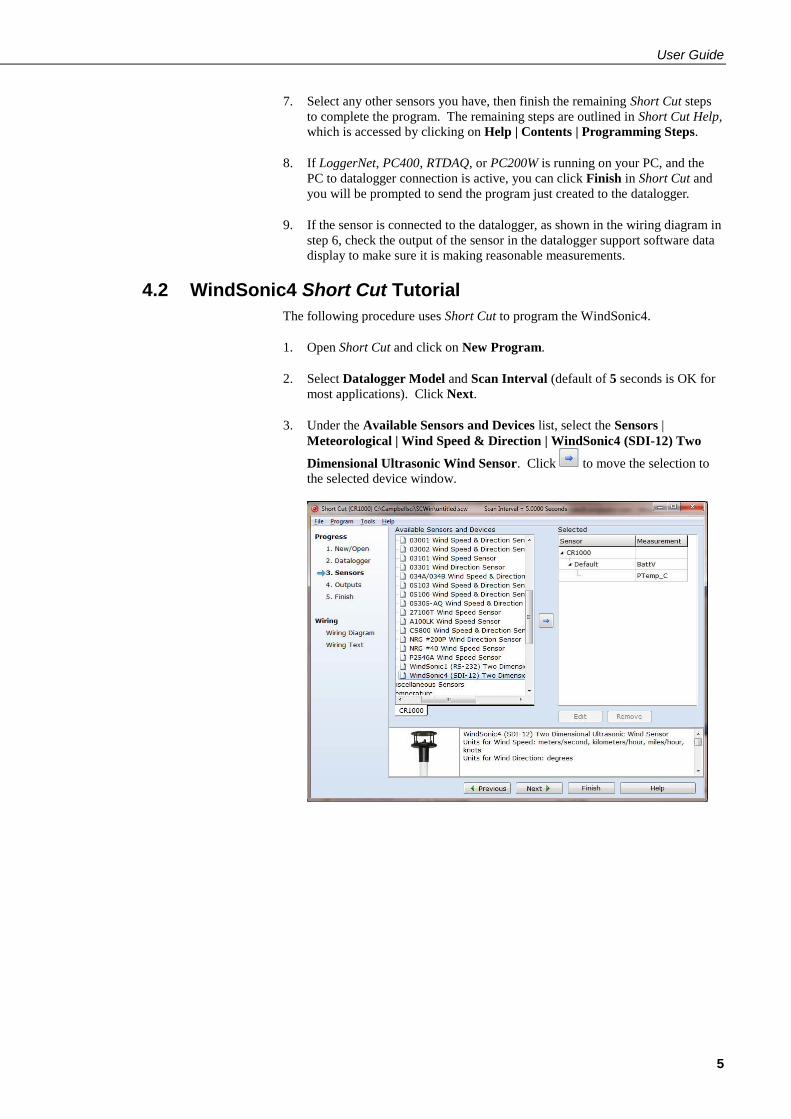
3. Under the Available Sensors and Devices list, select the Sensors |
Meteorological | Wind Speed & Direction | WindSonic4 (SDI-12) Two
Dimensional Ultrasonic Wind Sensor. Click to move the selection to
the selected device window.

WindSonic Ultrasonic Wind Sensor
6
4. Define the name of the public variables and SDI-12 Address. Variables
default to WindDir, WS_ms, and WSDiag that hold the wind direction
measurements, wind speed measurements, and diagnostic code. The SDI-12
Address defaults to 0. Select the desired units of measurement for the wind
speed. Units default to metres/seconds.
5. After selecting the sensor, click at the left of the screen on Wiring Diagram
to see how the sensor is to be wired to the datalogger. The wiring diagram
can be printed out now or after more sensors are added.

User Guide
7
5. Overview The WindSonic is an ultrasonic anemometer for measuring wind direction and
wind speed. It uses two pairs of orthogonally oriented transducers to sense
horizontal wind. The transducers bounce the ultrasonic signal from a hood,
minimizing the effects of transducer shadowing and flow distortion.
Detailed information on the Gill WindSonic is available in the manual published
by Gill Instruments, Ltd. and can be found at
www.gill.co.uk/products/anemometer/windsonic.htm. This manual serves as a
guide for interfacing the WindSonic to Campbell Scientific dataloggers. The
WindSonic is available in two versions. Option 1 WindSonic (WindSonic1)
outputs data using the RS-232 interface. Option 4 WindSonic (WindSonic4)
outputs data using the SDI-12 interface.
For the CR800-series, CR1000, or CR3000 dataloggers, the WindSonic1 connects
to control/serial ports (COMn). For the CR6, the WindSonic1 connects to control
ports or universal channels configured for serial communication. Two ports make
a COMn serial port; for example, C1 and C2 are COM1. A maximum of four
WindSonic1 anemometers can be connected to a single CR1000 or CR3000
datalogger, while two can be connected to the CR800-series control ports
(COMn). Up to eight anemometers can be connected to a CR6. Additional
WindSonic1 anemometers can be interfaced using an RJ45 terminal block adapter
(pn #31897) (CR6 only) or SDM-SIO1. Campbell Scientific does not recommend
using the CR200(X)-series or CR5000 with the WindSonic1 because of their
limited serial support using the control ports.
Campbell Scientific recommends that the WindSonic4, SDI-12 interface, be used
with CR200(X)-series or CR5000 dataloggers. SDI-12 is a three-wire digital
interface standard used by processor-based sensors and digital recording devices.
The CR6, CR800-series, CR1000, and CR3000 dataloggers also support the SDI-
12 interface.
The WindSonic includes a user-specified cable to interface to a Campbell
Scientific datalogger. The WindSonic’s cable can terminate in:
Connector that attaches to a prewired enclosure (option –PW). Refer to
www.campbellsci.com/prewired-enclosures for more information.
A serial cable (WINDSONICRCBL-L) is available for interfacing a WindSonic1
or WindSonic4 to a PC running the manufacturer’s PC support software. The
cable and software are used during troubleshooting or to change settings in the
WindSonic1 for a specific application. A copy of this PC support software is
available at www.gill.co.uk/main/software.html. WindView is used for
WindSonics with serial numbers of 0810001 or greater, and WindCom is used for
WindSonics with serial numbers that are less than 0810001.

WindSonic Ultrasonic Wind Sensor
8
6. Specifications Features:
Low maintenance—no moving parts significantly reduces maintenance
cost and time
Minimum detectable wind speed of 0.01 metres per second
Compatible with Campbell Scientific CRBasic Dataloggers: CR6,
CR200(X) series (WindSonic4 only), CR800-series, CR1000, CR3000,
and CR5000 (WindSonic4 only)
6.1 Wind Direction
Operating Range: 0 to 359° (no dead band)
Accuracy: ±3°
Output Resolution: 1°
6.2 Wind Speed
Operating Range: 0 to 60 m s–1
Accuracy: ±2% @ 12 m s–1
Output Resolution: 0.01 m s–1
6.3 General Specifications
Output Signal: RS-232 (WindSonic1)
SDI-12 version 1.3 (WindSonic4); address factory
set to 0
Output Variables: wind direction, wind speed, and diagnostic or ux,
uy, and diagnostic (WindSonic4 only)
Measurement Frequency: 40 Hz block averaged to a programmable output
frequency, factory set to 1 Hz
Current Drain: ~15 mA continuous (WindSonic1)
<12 mA @ 12 V (WindSonic4)
Operating Temperature: –35 to 70 °C
Storage Temperature: –40 to 80 °C
Dimensions: 142 x 160 mm (5.6 x 6.3 in)
Weight: 500 g (1.1 lb)
Operating Humidity: <5% to 100% RH
User Guide
9
6.4 Campbell Scientific Factory Default Settings for the WindSonic1
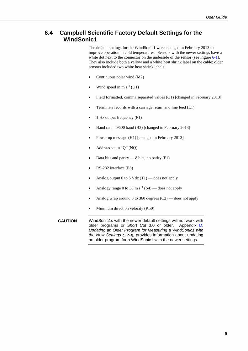
The default settings for the WindSonic1 were changed in February 2013 to
improve operation in cold temperatures. Sensors with the newer settings have a
white dot next to the connector on the underside of the sensor (see Figure 6-1).
They also include both a yellow and a white heat shrink label on the cable; older
sensors included two white heat shrink labels.
Continuous polar wind (M2)
Wind speed in m s–1
(U1)
Field formatted, comma separated values (O1) [changed in February 2013]
Terminate records with a carriage return and line feed (L1)
1 Hz output frequency (P1)
Baud rate – 9600 baud (B3) [changed in February 2013]
Power up message (H1) [changed in February 2013]
Address set to “Q” (NQ)
Data bits and parity — 8 bits, no parity (F1)
RS-232 interface (E3)
Analog output 0 to 5 Vdc (T1) — does not apply
Analogy range 0 to 30 m s–1
(S4) — does not apply
Analog wrap around 0 to 360 degrees (C2) — does not apply
Minimum direction velocity (K50)
WindSonic1s with the newer default settings will not work with older programs or Short Cut 3.0 or older. Appendix D, Updating an Older Program for Measuring a WindSonic1 with the New Settings (p. D-1), provides information about updating
an older program for a WindSonic1 with the newer settings.
CAUTION

WindSonic Ultrasonic Wind Sensor
10
Figure 6-1. White dot indicating that the WindSonic1 has the newer settings
7. Installation If you are programming your datalogger with Short Cut, skip Section 7.3, Wiring
(p. 11), and Section 7.4, Datalogger Programming (p. 13). Short Cut does this work
for you. See Section 4, Quickstart (p. 2), for a Short Cut tutorial.
7.1 Siting
Locate the WindSonic away from obstructions such as trees and buildings. The
distance between wind sensors and the nearest obstruction should be ten times the
height of the obstruction. If it is necessary to mount the WindSonic on the roof of
a building, the height of the sensor, above the roofline, should be at least 1.5 times
the height of the building. See Section 10, Siting References (p. 18), for a list of
references that discuss siting wind direction and speed sensors.
7.2 Mount the Sensor
The WindSonic is mounted using the components of the 17387 Mounting Pipe
Kit, which is shipped with the WindSonic (see Section 3.1, Ships With (p. 2)).
1. Thread the connector end of the cable through the tubing; start at the end
without the three threaded holes.
2. Attach the female mating connector on the cable to the male mating connector
located on the bottom of the WindSonic.
3. Secure the WindSonic to the tubing using the three #6-32 x 0.375-inch pan
head screws (pn #505).
4. Attach the tubing to a CM202, CM204, or CM206 crossarm via the CM220
Right Angle Mounting Kit (see Figure 7-1).
5. Mount the crossarm to the tripod or tower.
White Dot

User Guide
11
6. Orient the WindSonic so that the coloured North marker arrows point to True
North (see Figure 7-1). Appendix C, WindSonic Orientation (p. C-1), contains
detailed information on determining True North using a compass and the
magnetic declination for the site.
Figure 7-1. WindSonic1
7. Route the sensor cable along the underside of the crossarm to the tripod or
tower, and to the instrument enclosure.
8. Secure the cable to the crossarm and tripod or tower using cable ties.
7.3 Wiring
7.3.1 Datalogger to WindSonic1 Wiring
The CR800 series, CR1000, and CR3000 dataloggers support serial
communications with dedicated UART hardware on their control ports. They use
two control ports configured as a single communications (COMn) port. The CR6
uses two control ports or two universal channels configured as a single
communication port.
The WindSonic1 can also be connected to the CR6’s CPI/RS-232
port by using an RJ45 terminal block adapter (pn #31897).
Information about using this adapter is provided in Appendix E,
Using the CR6 Datalogger’s CPI/RS-232 Port (p. E-1).
NOTE

WindSonic Ultrasonic Wind Sensor
12
The WindSonic1 serial interface uses four wires as shown in Table 7-1.
Table 7-1. WindSonic1 to Datalogger Connections
Description Colour CRBasic Datalogger
WindSonic RxD Green Tx (COMn, Cn, or Un)
WindSonic TxD White Rx (COMn, Cn, or Un)
Power Red 12V
Serial/Power Reference Black G
Shield Clear G
The maximum cable length that can be used with a RS-232 interface
depends on the baud rate, the nominal resistance of the wire, the
capacitance between conductors, and the capacitance between the
conductors and the shield. According to the Electronic Industries
Association RS-232D standard, a rough rule of thumb is to limit
RS-232 cable lengths to 15.24 m (50 ft) or less at 9600 bps.
7.3.2 SDM-SIO1 Wiring
The SDM-SIO1 can be used to increase the number of sensors that a CR800-
series, CR1000, or CR3000 datalogger can measure. The SDM-SIO1 converts
RS-232 signals into Synchronous Device for Measurements (SDM). SDM is a
Campbell Scientific digital communications protocol used between Campbell
Scientific dataloggers and SDM peripherals. At a 1 Hz measurement rate, a
maximum of four WindSonic1 sensors can be measured by a datalogger. Table
7-2 describes the connections between a WindSonic1 and SDM-SIO1.
Table 7-2. WindSonic1 to SDM-SIO1 Connections
Description Colour SDM-SIO1
WindSonic RxD Green TX-Z
WindSonic TxD White RX-A
Power Red +12V
Serial/Power Reference Black G
Shield Clear G
7.3.3 WindSonic4 Wiring
The WindSonic4 interfaces to a Campbell Scientific datalogger using SDI-12.
SDI-12 is a three-wire interface used between processor-based sensors and digital
recorders (Table 7-3). Each SDI-12 sensor has a unique address. The factory-set
address for the WindSonic is 0. To change the SDI-12 address, see Section 8.2.1,
Changing the SDI-12 Address Using LoggerNet and a Datalogger (p. 16). At a 1
Hz measurement rate, a maximum of four WindSonic4s can be measured by a
datalogger.
NOTE

User Guide
13
Table 7-3. WindSonic4 to Datalogger Connections
Description Colour Datalogger
SDI-12 Data Green SDI-12 Input or Control Port
SDI-12 Power Red 12V
SDI-12 Reference Black G
Shield Clear G
7.4 Datalogger Programming
Short Cut is the best source for up-to-date datalogger programming code.
Programming code is needed,
when creating a program for a new datalogger installation
when adding sensors to an existing datalogger program
If your data acquisition requirements are simple, you can probably create and
maintain a datalogger program exclusively with Short Cut. If your data
acquisition needs are more complex, the files that Short Cut creates are a great
source for programming code to start a new program or add to an existing custom
program.
Short Cut cannot edit programs after they are imported and edited in
CRBasic Editor.
A Short Cut tutorial is available in Section 4, Quickstart (p. 2). If you wish to
import Short Cut code into CRBasic Editor to create or add to a customized
program, follow the procedure in Appendix A, Importing Short Cut Code (p. A-1).
Programming basics for CRBasic dataloggers are provided in the following
sections. Complete program examples for select CRBasic dataloggers can be
found in Appendix B, Example Programs (p. B-1). Programming basics and
programming examples for Edlog dataloggers are provided at
www.campbellsci.com\old-manuals.
7.4.1 WindSonic1 Programming
The WindSonic1 updates the RS-232 output to a user-set frequency. The CRBasic
dataloggers use the SerialInRecord() instruction to retrieve the latest record sent
by the WindSonic1 at the scan interval. This ensures that the most current wind
data is available for use by the program.
The datalogger and WindSonic1 each use their own internal clocks. These clocks
are not perfectly synchronized with each other and will drift in and out of phase.
This phase drift could cause missed samples because no new data was transmitted
to the datalogger in time for the next scan. The programs in this manual record
the number of missed records as no new data (nnd_TOT). A no new data error
will occur if the WindSonic1 is disconnected from the serial port, the WindSonic1
has no power, or the datalogger and WindSonic1 clocks have drifted out of phase
by one cycle.
Early versions of the datalogger operating system (OS) did not support serial
communication using control ports or the instruction SerialInRecord(). It may be
necessary to update the datalogger OS. Table 7-4 lists the OS versions that
support both serial communications using control ports and the SerialInRecord().
NOTE

WindSonic Ultrasonic Wind Sensor
14
The most current datalogger operating systems are available on the Campbell
Scientific website in the Support|Downloads section.
Table 7-4. CRBasic Datalogger Operating
Systems that Support RS-232
Communications and SerialInRecord()
Datalogger Model Operating System
CR6 1.0 or later
CR800-series 4.0 or later
CR1000 13.0 or later
CR3000 6.0 or later
7.5 WindSonic4 Programming
The WindSonic4 updates the SDI-12 output at a frequency of 1 Hz. The
SDI12Recorder() measurement instruction programs CRBasic dataloggers to
measure the WindSonic4. This instruction sends a request to the sensor to make a
measurement and then retrieves the measurement from the sensor. When using a
CR200(X), the SDI12Recorder() instruction has the following structure:
SDI12Recorder(Destination,OutString,Multiplier,Offset)
For the other CRBasic dataloggers, the SDI12Recorder() instruction has the
following syntax:
SDI12Recorder(Destination, SDIPort, SDIAddress, “SDICommand”, Multiplier,
Offset)
The Destination parameter needs to be a variable array with three elements. The
most appropriate SDI-12 command to retrieve data from the WindSonic4 is the
aRo!, where a is the WindSonic SDI-12 address and o is the data format option
(Table 7-5).
Table 7-5. WindSonic4 Data Format Option
Option (o) Output Units Comment
0
wind direction degrees
Compass polar coordinate system wind speed m s–1
diagnostic unitless
1
ux wind m s–1
Orthogonal right hand coordinate
system uy wind m s
–1
diagnostic unitless
Table 7-6 lists the datalogger OS version and revision that supports the SDI-12
aRo! command. The most current datalogger operating systems are available at
the Campbell Scientific website in the Support|Downloads section.
User Guide
15
Table 7-6. Datalogger Operating Systems
that Support the SDI-12 “aRo!” Command
Datalogger Model Operating System
CR6 1.0 or later
CR200(X)-series 3.0a or later
CR800-series 1.0 or later
CR1000 1.0 or later
CR3000 1.0 or later
CR5000 1.8 or later
See Section 8.2, SDI-12 Measurement Details (p. 15), for more information about
this instruction.
8. Operation
8.1 Sensor Configuration
To mimic a mechanical anemometer, the WindSonic’s output frequency must
match the datalogger’s scan frequency. The factory setting for the WindSonic1
and WindSonic4 is 1 Hz; for example, 1 output per second. The data output
frequency of the WindSonic4 cannot be changed.
The data output frequency of the WindSonic1 can be set to five discrete values
(see Table 8-1) using Gill’s PC support software and the RS-232 WindSonic to PC
cable.
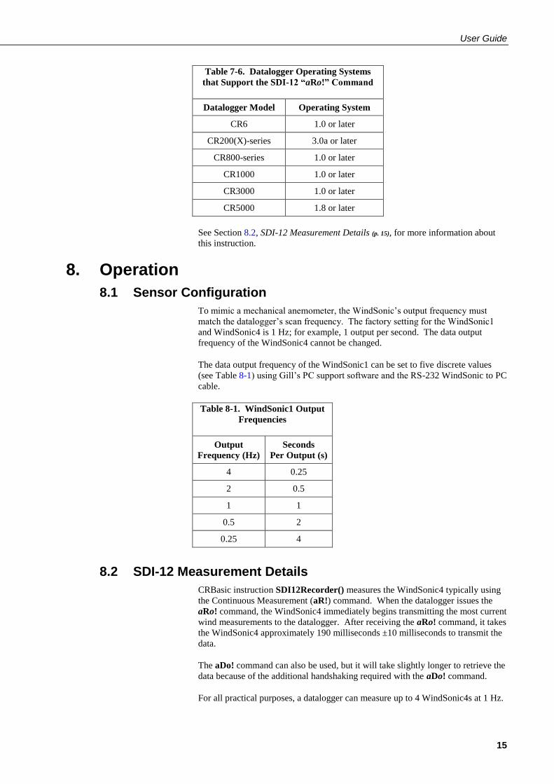
Table 8-1. WindSonic1 Output
Frequencies
Output
Frequency (Hz)
Seconds
Per Output (s)
4 0.25
2 0.5
1 1
0.5 2
0.25 4
8.2 SDI-12 Measurement Details
CRBasic instruction SDI12Recorder() measures the WindSonic4 typically using
the Continuous Measurement (aR!) command. When the datalogger issues the
aRo! command, the WindSonic4 immediately begins transmitting the most current
wind measurements to the datalogger. After receiving the aRo! command, it takes
the WindSonic4 approximately 190 milliseconds ±10 milliseconds to transmit the
data.
The aDo! command can also be used, but it will take slightly longer to retrieve the
data because of the additional handshaking required with the aDo! command.
For all practical purposes, a datalogger can measure up to 4 WindSonic4s at 1 Hz.

WindSonic Ultrasonic Wind Sensor
16
8.2.1 Changing the SDI-12 Address Using LoggerNet and a Datalogger
Up to ten WindSonic4s or other SDI-12 sensors can be connected to a single
datalogger control port. A datalogger can measure up to 4 WindSonic4 at 1 Hz.
Each SDI-12 device must have a unique SDI-12 address between 0 and 9. The
factory-set SDI-12 address for the WindSonic4 is 0. The WindSonic4 SDI-12
address is changed in software by issuing the aAb! command, where a is the
current address and b is the new address, to the WindSonic4 over the SDI-12
interface. The current address can be found by issuing the ?! command.
A computer running LoggerNet can be used to issue any valid SDI-12 command
through the datalogger to the WindSonic4. For a complete list of SDI-12
commands supported by the WindSonic4, see Section 11 of the Gill WindSonic
manual.
8.2.1.1 CR200(X)-series Datalogger
Connect a single WindSonic4 to the datalogger using Control Port C1/SDI12
as described in Section 7.3.3, WindSonic4 Wiring (p. 12), and download a
datalogger program that does not contain the SDI12Recorder() instruction.
In the LoggerNet Toolbar, navigate to and activate the Test|Terminal
Emulator … menu. The Terminal Emulator window will open. In the Select
Device menu, located in the lower left hand side of the window, select the
station.
Click on the Open Terminal button. If communications between the
datalogger and PC are successful, the red bar located in the upper left hand
side of the window will turn green.
Press the Enter key until the datalogger responds with the “CR200(X)>”
prompt (Figure 8-1).
To query the WindSonic4 for its current SDI-12 address, press the Enter key,
at the “CR200(X)>” prompt enter the command “SDI12>?!”, and press the
Enter key. The WindSonic4 will respond with the current SDI-12 address.
To change the SDI-12 address, press the Enter key, at the “CR200(X)>”
prompt enter the command “SDI12>aAb!”; where a is the current address
from the above step and b is the new address. The WindSonic4 will change
its address and the datalogger will exit the SDI-12 Transparent Mode and
respond with “Fail”.
Verify the new SDI-12 address. Press the Enter key, at the “CR200(X)>”
prompt enter the command “SDI12>?!” and press the Enter key. The
WindSonic4 will respond with the new address.
User Guide
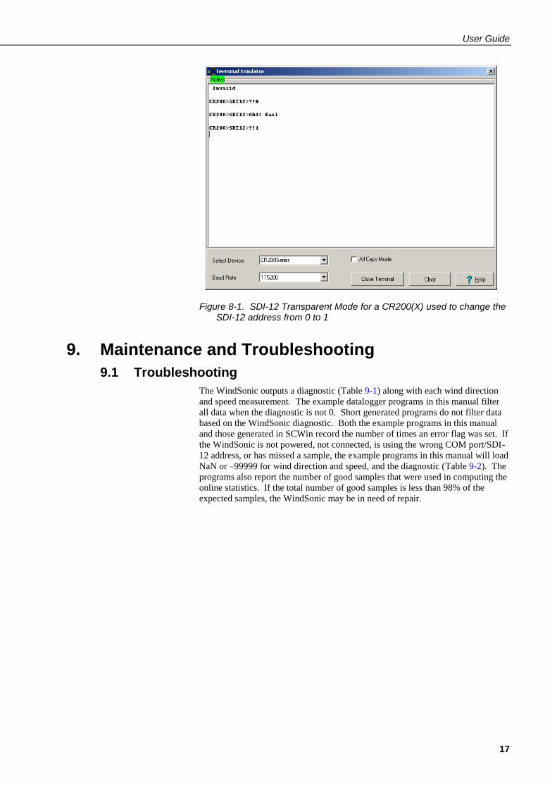
17
Figure 8-1. SDI-12 Transparent Mode for a CR200(X) used to change the SDI-12 address from 0 to 1
9. Maintenance and Troubleshooting
9.1 Troubleshooting
The WindSonic outputs a diagnostic (Table 9-1) along with each wind direction
and speed measurement. The example datalogger programs in this manual filter
all data when the diagnostic is not 0. Short generated programs do not filter data
based on the WindSonic diagnostic. Both the example programs in this manual
and those generated in SCWin record the number of times an error flag was set. If
the WindSonic is not powered, not connected, is using the wrong COM port/SDI-
12 address, or has missed a sample, the example programs in this manual will load
NaN or –99999 for wind direction and speed, and the diagnostic (Table 9-2). The
programs also report the number of good samples that were used in computing the
online statistics. If the total number of good samples is less than 98% of the
expected samples, the WindSonic may be in need of repair.

WindSonic Ultrasonic Wind Sensor
18
Table 9-1. Gill WindSonic Diagnostic Codes
Diagnostic Status Comment
0 Okay All okay
1 Axis 1 Failed Insufficient samples, possible path obstruction
2 Axis 2 Failed Insufficient samples, possible path obstruction
4 Both Axis Failed Insufficient samples, possible path obstruction
8 NVM error Non-volatile Memory checksum failed
9 ROM error Read Only Memory checksum failed
10 Maximum Gain Questionable wind measurements
Table 9-2. Example Datalogger Program Diagnostic Codes
Diagnostic Comment
NaN WindSonic not powered, not connected, wrong COM port/
SDI-12 address, or missed sample
9.2 Maintenance
There are no user-serviceable parts on the WindSonic. Keep the transducer paths
clear of any obstructions. When clearing the transducer paths, do not remove or
damage the transducer matching layer. The transducers can be gently cleaned
with a cloth and mild detergent. Do no use solvents and avoid scratching or
damaging the matching layers. The transducer’s matching layers are the “rubber”
caps on each of the transducers. Should the WindSonic be damaged, fail to output
data, or send a nonzero diagnostic, return it for repair (refer to the Assistance
section at the beginning of this manual for the process of returning a product to
Campbell Scientific). For more information, see Section 12, Maintenance and
Fault-Finding, in the manual published by Gill Instruments.
10. Siting References The following references give detailed information on siting wind direction and
wind speed sensors.
EPA, 1987: On-Site Meteorological Program Guidance for Regulatory Modelling
Applications, EPA-450/4-87-013, Office of Air Quality Planning and
Standards, Research Triangle Park, NC, 27711.
EPA, 1989: Quality Assurance Handbook for Air Pollution Measurements
System, Office of Research and Development, Research Triangle Park, NC,
27711.
The State Climatologist, 1985: Publication of the American Association of State
Climatologists: Height and Exposure Standards, for Sensors on Automated
Weather Stations, vol. 9, No. 4.
WMO, 1983: Guide to Meteorological Instruments and Methods of Observation,
World Meteorological Organization, No. 8, 5th edition, Geneva, Switzerland.

A-1
Appendix A. Importing Short Cut Code
This tutorial shows:
How to import a Short Cut program into a program editor for additional
refinement
How to import a wiring diagram from Short Cut into the comments of a
custom program
Short Cut creates files that can be imported into either CRBasic Editor. These
files normally reside in the C:\campbellsci\SCWin folder and have the following
extensions:
.DEF (wiring and memory usage information)
.CR6 (CR6 datalogger code)
.CR1 (CR1000 datalogger code)
.CR8 (CR800 datalogger code)
.CR3 (CR3000 datalogger code)
.CR2 (CR200(X) datalogger code)
.CR5 (CR5000 datalogger code)
Use the following procedure to import Short Cut code into CRBasic Editor (CR6,
CR1000, CR800, CR3000, CR200(X), CR5000 dataloggers).
1. Create the Short Cut program following the procedure in Section 4,
Quickstart (p. 2). Finish the program and exit Short Cut. Make note of the file
name used when saving the Short Cut program.
2. Open CRBasic Editor.
3. Click File | Open. Assuming the default paths were used when Short Cut was
installed, navigate to C:\CampbellSci\SCWin folder. The file of interest has a
“.CR6”, “.CR1”, “.CR8”, “.CR3”, “.CR2”, or “.CR5” extension, for CR6,
CR1000, CR800, CR3000, CR200(X), or CR5000 dataloggers, respectively.
Select the file and click Open.
4. Immediately save the file in a folder different from \Campbellsci\SCWin, or
save the file with a different file name.
Once the file is edited with CRBasic Editor, Short Cut can no longer
be used to edit the datalogger program. Change the name of the
program file or move it, or Short Cut may overwrite it next time it is
used.
5. The program can now be edited, saved, and sent to the datalogger.
6. Import wiring information to the program by opening the associated .DEF
file. Copy and paste the section beginning with heading “-Wiring for
CRXXX–” into the CRBasic program, usually at the head of the file. After
pasting, edit the information such that a ' character (single quotation mark)
begins each line. This character instructs the datalogger compiler to ignore
the line when compiling the datalogger code.
NOTE


B-1
Appendix B. Example Programs
B.1 WindSonic1 Programs
B.1.1 CR1000 WindSonic1 Program Using COMn Port
Table B-1. Wiring for CR1000 Example Program
Description Colour CR1000
WindSonic RxD Green COM1 Tx (C1)
WindSonic TxD White COM1 Rx (C2)
Power Red +12 Vdc
RS-232/Power Reference Black G
Shield Clear G
'CR1000 Series Datalogger Dim in_bytes_str As String * 21 Dim windsonic(4) As String Public nmbr_bytes_rtrnd Public wind_direction Public wind_speed Public diag Units wind_direction = degrees Units wind_speed = m/s Units diag = unitless Dim checksum_flg As Boolean Dim disable_flg As Boolean Dim n Units n = arb DataTable (stats,TRUE,-1) DataInterval (0,30,Min,10) WindVector (1,wind_speed,wind_direction,IEEE4,disable_flg,0,0,0) FieldNames ("mean_wind_speed,mean_wind_direction,std_wind_dir") Totalize (1,n,IEEE4,disable_flg) FieldNames ("samples_TOT") Totalize (1,n,IEEE4,diag<>1) FieldNames ("diag_1_TOT") Totalize (1,n,IEEE4,diag<>2) FieldNames ("diag_2_TOT") Totalize (1,n,IEEE4,diag<>4) FieldNames ("diag_4_TOT") Totalize (1,n,IEEE4,diag<>8) FieldNames ("diag_8_TOT") Totalize (1,n,IEEE4,diag<>9) FieldNames ("diag_9_TOT") Totalize (1,n,IEEE4,diag<>10) FieldNames ("diag_10_TOT") Totalize (1,n,IEEE4,nmbr_bytes_rtrnd<>0) FieldNames ("nnd_TOT") Totalize (1,n,IEEE4,nmbr_bytes_rtrnd<>0 IMP checksum_flg) FieldNames ("checksum_err_TOT") EndTable

Appendix B. Example Programs
B-2
BeginProg n = 1 SerialOpen (Com1,9600,3,0,108) Scan (1,Sec,3,0) 'Get data from WindSonic. SerialInRecord (Com1,in_bytes_str,&h02,0,&h0D0A,nmbr_bytes_rtrnd,01) SplitStr (windsonic(),in_bytes_str,",",4,4) 'Split the string and convert to floats. wind_direction = windsonic(1) wind_speed = windsonic(2) diag = windsonic(4) checksum_flg = ( (HexToDec (Right (in_bytes_str,2))) EQV (CheckSum (in_bytes_str,9,Len (in_bytes_str)-3)) ) disable_flg = ( NOT (checksum_flg) OR (nmbr_bytes_rtrnd=0) OR (diag<>0) ) CallTable stats NextScan EndProg
B.1.1 CR1000 WindSonic1 Program Using SDM-SIO1
Table B-2. Wiring for CR1000/SDM-SIO1
Program Example
Description Colour CR1000
WindSonic RxD Green TX-Z
WindSonic TxD White RX-A
Power Red +12 Vdc
RS-232/Power Reference Black G
Shield Clear G
'CR1000 Series Datalogger Dim in_bytes_str As String * 21 Dim windsonic(4) As String Public nmbr_bytes_rtrnd Public wind_direction Public wind_speed Public diag Units wind_direction = degrees Units wind_speed = m/s Units diag = unitless Dim checksum_flg As Boolean Dim disable_flg As Boolean Dim n Units n = arb DataTable (stats,TRUE,-1) DataInterval (0,30,Min,10) WindVector (1,wind_speed,wind_direction,IEEE4,disable_flg,0,0,0) FieldNames ("mean_wind_speed,mean_wind_direction,std_wind_dir") Totalize (1,n,IEEE4,disable_flg) FieldNames ("samples_TOT") Totalize (1,n,IEEE4,diag<>1) FieldNames ("diag_1_TOT") Totalize (1,n,IEEE4,diag<>2) FieldNames ("diag_2_TOT") Totalize (1,n,IEEE4,diag<>4) FieldNames ("diag_4_TOT") Totalize (1,n,IEEE4,diag<>8) FieldNames ("diag_8_TOT") Totalize (1,n,IEEE4,diag<>9) FieldNames ("diag_9_TOT") Totalize (1,n,IEEE4,diag<>10) FieldNames ("diag_10_TOT") Totalize (1,n,IEEE4,nmbr_bytes_rtrnd<>0) FieldNames ("nnd_TOT") Totalize (1,n,IEEE4,nmbr_bytes_rtrnd<>0 IMP checksum_flg) FieldNames ("checksum_err_TOT") EndTable
Appendix B. Example Programs
B-3
BeginProg n = 1 SerialOpen (40,9600,3,0,108) 'SDM-SIO1 SDM address set To 8. Scan (1,Sec,3,0) 'Get data from WindSonic. SerialInRecord (40,in_bytes_str,&h02,0,&h0D0A,nmbr_bytes_rtrnd,01) SplitStr (windsonic(),in_bytes_str,",",4,4) 'Split the string and convert to floats. wind_direction = windsonic(1) wind_speed = windsonic(2) diag = windsonic(4) checksum_flg = ( (HexToDec (Right (in_bytes_str,2))) EQV (CheckSum (in_bytes_str,9,Len (in_bytes_str)-3)) ) disable_flg = ( NOT (checksum_flg) OR (nmbr_bytes_rtrnd=0) OR (diag<>0) ) CallTable stats NextScan EndProg
B.2 WindSonic4 Programs
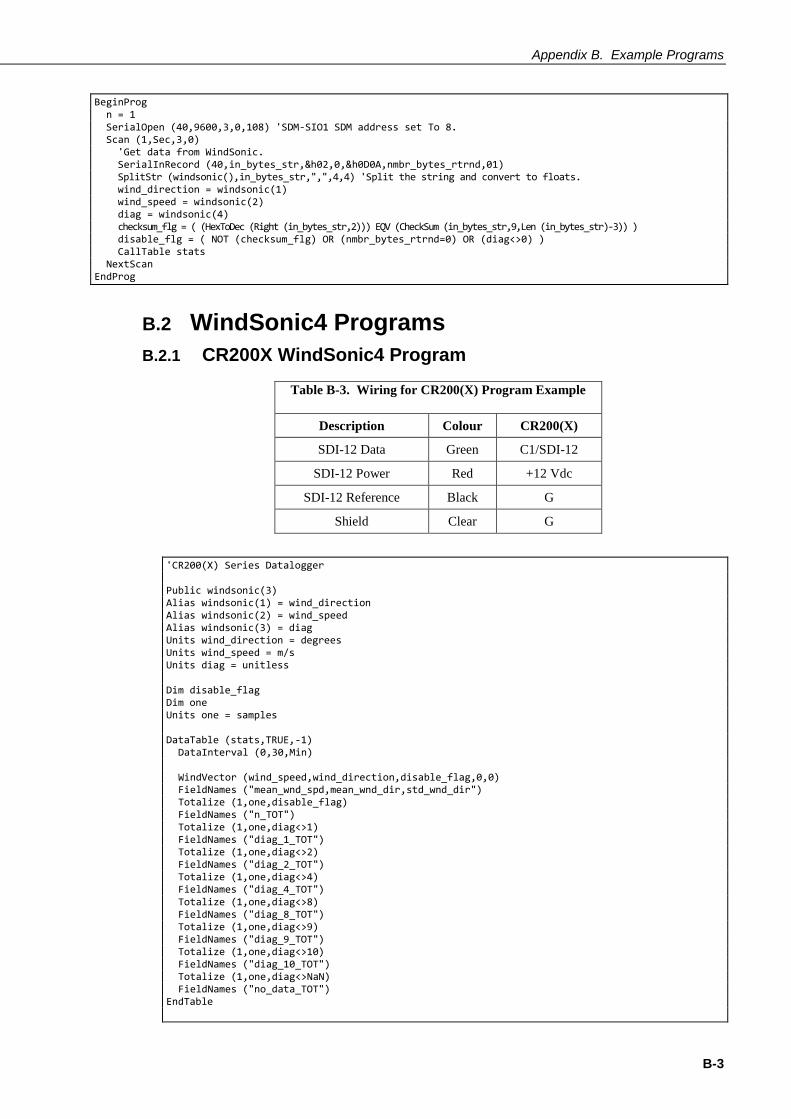
B.2.1 CR200X WindSonic4 Program
Table B-3. Wiring for CR200(X) Program Example
Description Colour CR200(X)
SDI-12 Data Green C1/SDI-12
SDI-12 Power Red +12 Vdc
SDI-12 Reference Black G
Shield Clear G
'CR200(X) Series Datalogger Public windsonic(3) Alias windsonic(1) = wind_direction Alias windsonic(2) = wind_speed Alias windsonic(3) = diag Units wind_direction = degrees Units wind_speed = m/s Units diag = unitless Dim disable_flag Dim one Units one = samples DataTable (stats,TRUE,-1) DataInterval (0,30,Min) WindVector (wind_speed,wind_direction,disable_flag,0,0) FieldNames ("mean_wnd_spd,mean_wnd_dir,std_wnd_dir") Totalize (1,one,disable_flag) FieldNames ("n_TOT") Totalize (1,one,diag<>1) FieldNames ("diag_1_TOT") Totalize (1,one,diag<>2) FieldNames ("diag_2_TOT") Totalize (1,one,diag<>4) FieldNames ("diag_4_TOT") Totalize (1,one,diag<>8) FieldNames ("diag_8_TOT") Totalize (1,one,diag<>9) FieldNames ("diag_9_TOT") Totalize (1,one,diag<>10) FieldNames ("diag_10_TOT") Totalize (1,one,diag<>NaN) FieldNames ("no_data_TOT") EndTable

Appendix B. Example Programs
B-4
BeginProg one = 1 Scan (1,Sec) SDI12Recorder (wind_direction,0R0!,1,0) If (wind_direction = NAN ) Then wind_speed = NAN diag = NAN EndIf disable_flag = (wind_direction=NAN) OR (diag<>0) CallTable stats NextScan EndProg
B.2.2 CR800 WindSonic4 Program
Table B-4. Wiring for CR800 Program Example
Description Colour CR800
SDI-12 data Green C1
SDI-12 power Red +12 Vdc
SDI-12 reference Black G
shield Clear G
'CR800 Series Datalogger Public windsonic(3) Alias windsonic(1) = wind_direction Alias windsonic(2) = wind_speed Alias windsonic(3) = diag Units wind_direction = degrees Units wind_speed = m/s Units diag = unitless Dim disable_flag AS Boolean Dim one Units one = samples DataTable (stats,TRUE,-1) DataInterval (0,30,Min,10) WindVector (1,wind_speed,wind_direction,IEEE4,disable_flag,0,0,0) FieldNames ("mean_wind_speed,mean_wind_direction,std_wind_dir") Totalize (1,one,IEEE4,disable_flag) FieldNames ("n_TOT") Totalize (1,one,IEEE4,diag<>1) FieldNames ("diag_1_TOT") Totalize (1,one,IEEE4,diag<>2) FieldNames ("diag_2_TOT") Totalize (1,one,IEEE4,diag<>4) FieldNames ("diag_4_TOT") Totalize (1,one,IEEE4,diag<>8) FieldNames ("diag_8_TOT") Totalize (1,one,IEEE4,diag<>9) FieldNames ("diag_9_TOT") Totalize (1,one,IEEE4,diag<>10) FieldNames ("diag_10_TOT") Totalize (1,one,IEEE4,diag<>NAN) FieldNames ("nnd_TOT") EndTable BeginProg one = 1 Scan (1,Sec,3,0) SDI12Recorder (wind_direction,1,0,"R0!",1,0) If ( wind_direction = NAN ) Then

Appendix B. Example Programs
B-5
wind_speed = NAN diag = NAN EndIf disable_flag = (wind_direction=NAN) OR (diag<>0) CallTable stats NextScan EndProg

Appendix B. Example Programs
B-6
C-1
Appendix C. WindSonic Orientation
C.1 Determining True North and Sensor Orientation Orientation of the wind direction sensor is done after the datalogger has been
programmed, and the location of True North has been determined. True North is
usually found by reading a magnetic compass and applying the correction for
magnetic declination; where magnetic declination is the number of degrees between
True North and Magnetic North. Magnetic declination for a specific site can be
obtained from a USGS map, local airport, or through a computer service offered by
the USGS at www.ngdc.noaa.gov/geomag. A general map showing magnetic
declination throughout the world is shown in Figure C-1.
Declination angles east of True North are considered negative, and are subtracted
from 0 degrees to get True North as shown in Figure C-2. Declination angles west of
True North are considered positive, and are added to 0 degrees to get True North as
shown in Figure C-3. For example, the declination for Logan, Utah is 14 East. True
North is 360 - 14, or 346 as read on a compass.
Orientation is most easily done with two people, one to aim and adjust the sensor,
while the other observes the wind direction displayed by the datalogger.
1. Establish a reference point on the horizon for True North.
2. Sighting down the instrument center line, aim the nose cone, or counterweight at
True North. Display the input location or variable for wind direction using a
hand-held keyboard display, PC, or palm.
3. Loosen the u-bolt on the CM220 or the set screws on the Nu-Rail that secure the
base of the sensor to the crossarm. While holding the vane position, slowly
rotate the sensor base until the datalogger indicates 0 degrees. Tighten the set
screws.

Appendix C. WindSonic Orientation
C-2
Figure C-1. Magnetic Declination at 2012.5 (degrees relative to true north, positive is east)
Figure C-2. Declination Angles East of True North Are Subtracted From 0 to Get True North

Appendix C. WindSonic Orientation
C-3
Figure C-3. Declination Angles West of True North Are Added to 0 to Get True North
C.2 Online Magnetic Declination Calculator The magnetic declination calculator web calculator published by NOAA’s
Geophysical Data Centre is available at the following url
www.ngdc.noaa.gov/geomagmodels/Declination.jsp. After the web page loads,
enter the site zip code, or longitude and latitude, then click on the “Compute
Declination” button (Figure A-4).
Figure C-4. NOAA Web Calculator

Appendix C. WindSonic Orientation
C-4
The declination for Logan, UT is 12.4 degrees (3 June 2010). As shown in Figure
C-4, the declination for Utah is positive (east of north), so true north for this site is
360 – 12.4, or 347.6 degrees. The annual change is -7 minutes/year or 7 minutes
west per year.

D-1
Appendix D. Updating an Older Program for Measuring a WindSonic1 with the New Settings
In February 2013, the settings of the WindSonic1 sensor were changed to improve
operation in cold temperatures. The communication baud rate has been changed
from 38,400 to 9600 bps, and the data output structure has been changed to the
manufacturer’s default. Section 6.4, Campbell Scientific Factory Default Settings
for the WindSonic1 (p. 9), lists the newer default settings.
Sensors with the new settings can be identified by a small white painted dot next
to the connector on the underside of the sensor. New sensor cables include both a
yellow and white heat shrink label; older sensor cables had two white heat shrink
labels. Because cables are interchangeable between new and old sensors, the best
check is to look for the painted dot.
Sensors with newer settings will NOT work with older programs written for sensors set to 38,400 baud or Short Cut version 3.0 or older.
Older WindSonic1 programs can be changed by using CRBasic Editor or by
cutting and pasting relevant sections from the updated manual. For additional
support, contact Campbell Scientific at +44(0)1509 828 888 or email
Programming examples shown below come from the old and new WindSonic
manuals. Programs are not complete, but show the relevant sections to be
changed.
Old CR1000 Program (Section 6.1 of 7/10 WindSonic manual)
(Public variables change. Data table structure stays the same.)
Public windsonic(4) Alias windsonic(1) = wind_direction Alias windsonic(2) = wind_speed Alias windsonic(3) = diag Alias windsonic(4) = nmbr_bytes_rtrnd Units wind_direction = degrees Units wind_speed = m/s Units diag = unitless Dim in_bytes_str As String * 21 Dim checksum_flg As Boolean Dim disable_flg As Boolean Dim n Units n = arb BeginProg n = 1 SerialOpen (Com1,38400,3,0,49) Scan (1,Sec,3,0) SerialInRecord (Com1,in_bytes_str,&h02,0,&h0D0A,nmbr_bytes_rtrnd,00) wind_direction = Mid (in_bytes_str,3,3) wind_speed = Mid (in_bytes_str,7,6) diag = Mid (in_bytes_str,16,2) checksum_flg = ( (HexToDec (Mid (in_bytes_str,20,2))) EQV (CheckSum(in_bytes_str,9,18)) ) disable_flg = (NOT (checksum_flg) OR (nmbr_bytes_rtrnd=0) OR (diag<>0))
CAUTION

Appendix D. Updating an Older Program for Measuring a WindSonic1 with the New Settings
D-2
New CR1000 Program (Appendix B.1.1)
(Public variables change. Data table structure stays the same.)
Dim windsonic(4) As String Public wind_direction Public wind_speed Public diag Public nmbr_bytes_rtrnd Units wind_direction = degrees Units wind_speed = m/s Units diag = unitless Dim in_bytes_str As String * 21 Dim checksum_flg As Boolean Dim disable_flg As Boolean Dim n Units n = arb BeginProg n = 1 SerialOpen (Com1,9600,3,0,105) Scan (1,Sec,3,0) 'Get data from WindSonic. SerialInRecord (Com1,in_bytes_str,&h02,0,&h0D0A,nmbr_bytes_rtrnd,01) SplitStr (windsonic(),in_bytes_str,",",4,4) 'Split the string and convert to floats. wind_direction = windsonic(1) wind_speed = windsonic(2) diag = windsonic(4) checksum_flg = ( (HexToDec (Right (in_bytes_str,2))) EQV (CheckSum (in_bytes_str,9,Len (in_bytes_str)-3)) ) disable_flg = ( NOT (checksum_flg) OR (nmbr_bytes_rtrnd=0) OR(diag<>0) )
Old CR1000 SDM-SIO1 Program (Section 6.2 of 7/10 WindSonic manual)
(Public variables change. Data table structure stays the same.)
Public windsonic(4) Alias windsonic(1) = wind_direction Alias windsonic(2) = wind_speed Alias windsonic(3) = diag Alias windsonic(4) = nmbr_bytes_rtrnd Units wind_direction = degrees Units wind_speed = m/s Units diag = unitless Dim in_bytes_str As String * 21 Dim checksum_flg As Boolean Dim disable_flg As Boolean Dim n Units n = arb BeginProg n = 1 SerialOpen (40,38400,3,0,49) ‘SDM-SIO1 SDM address set to 8. Scan (1,Sec,3,0) 'Get data from WindSonic. SerialInRecord (40,in_bytes_str,&h02,0,&h0D0A,nmbr_bytes_rtrnd,00) wind_direction = Mid (in_bytes_str,3,3) wind_speed = Mid (in_bytes_str,7,6) diag = Mid (in_bytes_str,16,2) checksum_flg = ( (HexToDec (Mid (in_bytes_str,20,2))) EQV (CheckSum(in_bytes_str,9,18)) ) disable_flg = (NOT (checksum_flg) OR (nmbr_bytes_rtrnd=0) OR (diag<>0))

Appendix D. Updating an Older Program for Measuring a WindSonic1 with the New Settings
D-3
New CR1000 SDM-SIO1 Program (from Appendix B.1.2)
(Public variables change. Data table structure stays the same.)
Dim windsonic(4) As String Public wind_direction Public wind_speed Public diag Public nmbr_bytes_rtrnd Units wind_direction = degrees Units wind_speed = m/s Units diag = unitless Dim in_bytes_str As String * 21 Dim checksum_flg As Boolean Dim disable_flg As Boolean Dim n Units n = arb BeginProg n = 1 SerialOpen (40,9600,3,0,105) 'SDM-SIO1 SDM address set To 8. Scan (1,Sec,3,0) 'Get data from WindSonic. SerialInRecord (40,in_bytes_str,&h02,0,&h0D0A,nmbr_bytes_rtrnd,01) SplitStr (windsonic(),in_bytes_str,",",4,4) 'Split the string and convert to floats. wind_direction = windsonic(1) wind_speed = windsonic(2) diag = windsonic(4) checksum_flg = ( (HexToDec (Right (in_bytes_str,2))) EQV (CheckSum(in_bytes_str,9,Len (in_bytes_str)-3)) ) disable_flg = ( NOT (checksum_flg) OR (nmbr_bytertrnd=0) OR (diag<>0) )

Appendix D. Updating an Older Program for Measuring a WindSonic1 with the New Settings
D-4

E-1
Appendix E. Using the CR6 Datalogger’s CPI/RS-232 Port
An RJ45 terminal block adapter (pn #31897) allows the WindSonic1 to be
connected to the CPI/RS-232 port on the CR6. The CPI/RS-232 port is typically
only used if the control ports or universal channels are not available. Table E-1
provides information about connecting the WindSonic1 to the adapter and CR6.
Table E-1. CPI/RS-232 Connections
WindSonic1 Wire
Colour
RJ45 Terminal Block
Connections
CR6 Connection
Green (RXD) PIN 1 TXD
White (TXD) PIN 2 RXD
Red (12 to 24 Vdc) 12V
Black (Power Ground) G
Clear (Shield – Ground) G
RJ45 Connector CPI/RS-232 Port
'CR6 Series Datalogger 'WindSonic1 Wiring 'RED: CR6 12V 'GREEN: PIN 1 (RJ45 TERMINAL ADAPTER) 'WHITE: PIN 2 (RJ45 TERMINAL ADAPTER) 'BLACK: CR6 G 'CLEAR: CR6 G Public PTemp, batt_volt 'Gill Sonic RS232 variables Public Windsonic(4) As String Public Wind_Dir : Units Wind_Dir = Deg Public WS_ms : Units WS_ms = m/s Public diag : Units diag = unitless Public WindSpd_mph : Units WindSpd_mph = mph Public nmbr_bytes_rtrnd Dim in_bytes_str As String * 21 Dim disable_flag As Boolean Dim checksum_flg As Boolean Dim one = {1} 'Define Data Tables. DataTable (Test,1,9999) 'Set table size to # of records, or -1 to autoallocate. DataInterval (0,15,Sec,10) Minimum (1,batt_volt,FP2,0,False) Sample (1,PTemp,FP2) EndTable

Appendix E. Using the CR6 Datalogger’s CPI/RS-232 Port
E-2
'Main Program BeginProg SerialOpen (ComRS232,9600,3,0,432) Scan (3,Sec,0,0) PanelTemp (PTemp,15000) Battery (Batt_volt) 'Gill WindSonic1 2-D Sonic SerialInRecord (ComRS232,in_bytes_str,&h02,0,&h0d0a,nmbr_bytes_rtrnd,01) SplitStr (Windsonic(),in_bytes_str,",",4,4) Wind_Dir = Windsonic(1) WS_ms = Windsonic(2) diag = Windsonic(4) checksum_flg = ( (HexToDec (Right (in_bytes_str,2))) EQV (CheckSum (in_bytes_str,9,Len (in_bytes_str)-3)) ) disable_flag = ( NOT (checksum_flg) OR (nmbr_bytes_rtrnd=0) OR (diag<>0) ) WindSpd_mph = WS_ms * 2.236936 'Enter other measurement instructions 'Call Output Tables 'Example: CallTable Test NextScan EndProg


CAMPBELL SCIENTIFIC COMPANIES
Campbell Scientific, Inc. (CSI)
815 West 1800 North Logan, Utah 84321 UNITED STATES
www.campbellsci.com [email protected]
Campbell Scientific Africa Pty. Ltd. (CSAf) PO Box 2450
Somerset West 7129 SOUTH AFRICA
www.csafrica.co.za [email protected]
Campbell Scientific Southeast Asia Co., Ltd. 877/22 Nirvana@Work, Rama 9 Road
Suan Luang Subdistrict, Suan Luang District Bangkok 10250
THAILAND www.campbellsci.asia [email protected]
Campbell Scientific Australia Pty. Ltd. (CSA) PO Box 8108
Garbutt Post Shop QLD 4814 AUSTRALIA
www.campbellsci.com.au [email protected]
Campbell Scientific do Brazil Ltda. (CSB) Rua Apinagés, nbr. 2018 - Perdizes
CEP: 01258-00 São Paulo SP BRAZIL www.campbellsci.com.br [email protected]
Campbell Scientific Canada Corp. (CSC) 14532 – 131 Avenue NW
Edmonton, Alberta T5L 4X4 CANADA
www.campbellsci.ca [email protected]
Campbell Scientific Centro Caribe S.A. (CSCC) 300N Cementerio, Edificio Breller
Santo Domingo, Heredia 40305 COSTA RICA
www.campbellsci.cc [email protected]
Campbell Scientific Ltd. (CSL) 80 Hathern Road, Shepshed, Loughborough LE12 9GX
UNITED KINGDOM www.campbellsci.co.uk [email protected]
Campbell Scientific Ltd. (France) 3 Avenue de la Division Leclerc
92160 ANTONY FRANCE
www.campbellsci.fr [email protected]
Campbell Scientific Spain, S. L. Avda. Pompeu Fabra 7-9
Local 1 - 08024 BARCELONA SPAIN
www.campbellsci.es [email protected]
Campbell Scientific Ltd. (Germany) Fahrenheitstrasse13, D-28359 Bremen
GERMANY www.campbellsci.de [email protected]
Campbell Scientific (Beijing) Co., Ltd. 8B16, Floor 8 Tower B, Hanwei Plaza
7 Guanghua Road, Chaoyang, Beijing 100004 P.R. CHINA
www.campbellsci.com [email protected]
Please visit www.campbellsci.eu to obtain contact information for your local EU or International representative.