sdm-sio1a / sdm-sio4a - campbell sci€¦ · precautions danger — many hazards are associated...
TRANSCRIPT

INST
RU
CT
ION
MA
NU
AL
SDM-SIO1A and SDM-SIO4A Serial Input/Output Modules
1/18
C o p y r i g h t © 2 0 1 6 - 2 0 1 7C a m p b e l l S c i e n t i f i c , I n c .


Guarantee
This equipment is guaranteed against defects in materials and workmanship.
We will repair or replace products which prove to be defective during the
guarantee period as detailed on your invoice, provided they are returned to us
prepaid. The guarantee will not apply to:
Equipment which has been modified or altered in any way without the
written permission of Campbell Scientific
Batteries
Any product which has been subjected to misuse, neglect, acts of God or
damage in transit.
Campbell Scientific will return guaranteed equipment by surface carrier
prepaid. Campbell Scientific will not reimburse the claimant for costs incurred
in removing and/or reinstalling equipment. This guarantee and the Company’s
obligation thereunder is in lieu of all other guarantees, expressed or implied,
including those of suitability and fitness for a particular purpose. Campbell
Scientific is not liable for consequential damage.
Please inform us before returning equipment and obtain a Repair Reference
Number whether the repair is under guarantee or not. Please state the faults as
clearly as possible, and if the product is out of the guarantee period it should
be accompanied by a purchase order. Quotations for repairs can be given on
request. It is the policy of Campbell Scientific to protect the health of its
employees and provide a safe working environment, in support of this policy a
“Declaration of Hazardous Material and Decontamination” form will be
issued for completion.
When returning equipment, the Repair Reference Number must be clearly
marked on the outside of the package. Complete the “Declaration of
Hazardous Material and Decontamination” form and ensure a completed copy
is returned with your goods. Please note your Repair may not be processed if
you do not include a copy of this form and Campbell Scientific Ltd reserves
the right to return goods at the customers’ expense.
Note that goods sent air freight are subject to Customs clearance fees which
Campbell Scientific will charge to customers. In many cases, these charges are
greater than the cost of the repair.
Campbell Scientific Ltd,
80 Hathern Road,
Shepshed, Loughborough, LE12 9GX, UK
Tel: +44 (0) 1509 601141
Fax: +44 (0) 1509 270924Email: [email protected]
www.campbellsci.co.uk


PLEASE READ FIRST
About this manual
Please note that this manual was originally produced by Campbell Scientific Inc. primarily for the North
American market. Some spellings, weights and measures may reflect this origin.
Some useful conversion factors:
Area: 1 in2 (square inch) = 645 mm
2
Length: 1 in. (inch) = 25.4 mm
1 ft (foot) = 304.8 mm
1 yard = 0.914 m
1 mile = 1.609 km
Mass: 1 oz. (ounce) = 28.35 g
1 lb (pound weight) = 0.454 kg
Pressure: 1 psi (lb/in2) = 68.95 mb
Volume: 1 UK pint = 568.3 ml
1 UK gallon = 4.546 litres
1 US gallon = 3.785 litres
In addition, while most of the information in the manual is correct for all countries, certain information
is specific to the North American market and so may not be applicable to European users.
Differences include the U.S standard external power supply details where some information (for
example the AC transformer input voltage) will not be applicable for British/European use. Please note,
however, that when a power supply adapter is ordered it will be suitable for use in your country.
Reference to some radio transmitters, digital cell phones and aerials may also not be applicable
according to your locality.
Some brackets, shields and enclosure options, including wiring, are not sold as standard items in the
European market; in some cases alternatives are offered. Details of the alternatives will be covered in
separate manuals.
Part numbers prefixed with a “#” symbol are special order parts for use with non-EU variants or for
special installations. Please quote the full part number with the # when ordering.
Recycling information
At the end of this product’s life it should not be put in commercial or domestic refuse but
sent for recycling. Any batteries contained within the product or used during the
products life should be removed from the product and also be sent to an appropriate
recycling facility.
Campbell Scientific Ltd can advise on the recycling of the equipment and in some cases
arrange collection and the correct disposal of it, although charges may apply for some
items or territories.
For further advice or support, please contact Campbell Scientific Ltd, or your local agent.
Campbell Scientific Ltd, 80 Hathern Road, Shepshed, Loughborough, LE12 9GX,
UK Tel: +44 (0) 1509 601141 Fax: +44 (0) 1509 270924Email: [email protected]
www.campbellsci.co.uk


Precautions DANGER — MANY HAZARDS ARE ASSOCIATED WITH INSTALLING, USING, MAINTAINING, AND WORKING ON OR AROUND TRIPODS, TOWERS, AND ANY ATTACHMENTS TO TRIPODS AND TOWERS SUCH AS SENSORS, CROSSARMS, ENCLOSURES, ANTENNAS, ETC. FAILURE TO PROPERLY AND COMPLETELY ASSEMBLE, INSTALL, OPERATE, USE, AND MAINTAIN TRIPODS, TOWERS, AND ATTACHMENTS, AND FAILURE TO HEED WARNINGS, INCREASES THE RISK OF DEATH, ACCIDENT, SERIOUS INJURY, PROPERTY DAMAGE, AND PRODUCT FAILURE. TAKE ALL REASONABLE PRECAUTIONS TO AVOID THESE HAZARDS. CHECK WITH YOUR ORGANIZATION'S SAFETY COORDINATOR (OR POLICY) FOR PROCEDURES AND REQUIRED PROTECTIVE EQUIPMENT PRIOR TO PERFORMING ANY WORK.
Use tripods, towers, and attachments to tripods and towers only for purposes for which they are designed. Do not exceed design limits. Be familiar and comply with all instructions provided in product manuals. Manuals are available at www.campbellsci.eu or by telephoning +44(0) 1509 828 888 (UK). You are responsible for conformance with governing codes and regulations, including safety regulations, and the integrity and location of structures or land to which towers, tripods, and any attachments are attached. Installation sites should be evaluated and approved by a qualified engineer. If questions or concerns arise regarding installation, use, or maintenance of tripods, towers, attachments, or electrical connections, consult with a licensed and qualified engineer or electrician.
General • Prior to performing site or installation work, obtain required approvals and permits. Comply with all
governing structure-height regulations, such as those of the FAA in the USA.• Use only qualified personnel for installation, use, and maintenance of tripods and towers, and any
attachments to tripods and towers. The use of licensed and qualified contractors is highly recommended.• Read all applicable instructions carefully and understand procedures thoroughly before beginning work.• Wear a hardhat and eye protection, and take other appropriate safety precautions while working on or
around tripods and towers.• Do not climb tripods or towers at any time, and prohibit climbing by other persons. Take reasonable
precautions to secure tripod and tower sites from trespassers.• Use only manufacturer recommended parts, materials, and tools.
Utility and Electrical • You can be killed or sustain serious bodily injury if the tripod, tower, or attachments you are installing,
constructing, using, or maintaining, or a tool, stake, or anchor, come in contact with overhead orunderground utility lines.
• Maintain a distance of at least one-and-one-half times structure height, or 20 feet, or the distancerequired by applicable law, whichever is greater, between overhead utility lines and the structure (tripod,tower, attachments, or tools).
• Prior to performing site or installation work, inform all utility companies and have all underground utilitiesmarked.
• Comply with all electrical codes. Electrical equipment and related grounding devices should be installedby a licensed and qualified electrician.
Elevated Work and Weather • Exercise extreme caution when performing elevated work.• Use appropriate equipment and safety practices.• During installation and maintenance, keep tower and tripod sites clear of un-trained or non-essential
personnel. Take precautions to prevent elevated tools and objects from dropping.• Do not perform any work in inclement weather, including wind, rain, snow, lightning, etc.
Maintenance • Periodically (at least yearly) check for wear and damage, including corrosion, stress cracks, frayed cables,
loose cable clamps, cable tightness, etc. and take necessary corrective actions.• Periodically (at least yearly) check electrical ground connections.
WHILE EVERY ATTEMPT IS MADE TO EMBODY THE HIGHEST DEGREE OF SAFETY IN ALL CAMPBELL SCIENTIFIC PRODUCTS, THE CUSTOMER ASSUMES ALL RISK FROM ANY INJURY RESULTING FROM IMPROPER INSTALLATION, USE, OR MAINTENANCE OF TRIPODS, TOWERS, OR ATTACHMENTS TO TRIPODS AND TOWERS SUCH AS SENSORS, CROSSARMS, ENCLOSURES, ANTENNAS, ETC.


i
Table of Contents PDF viewers: These page numbers refer to the printed version of this document. Use the PDF reader bookmarks tab for links to specific sections.
1. Introduction ................................................................ 1
2. Precautions ................................................................ 2
3. Initial Inspection ......................................................... 3
4. Overview ..................................................................... 3
5. Specifications ............................................................. 45.1 Supported Data Rates and Protocols .................................................... 4 5.2 Electrical Parameters ............................................................................ 5
5.2.1 Current Consumption .................................................................... 5 5.2.2 Voltage Specifications .................................................................. 6 5.2.3 Compliance ................................................................................... 6
5.3 Temperature and Humidity Ranges ..................................................... 6 5.4 Dimensions and Weight ....................................................................... 6
5.4.1 SDM-SIO1A ................................................................................. 6 5.4.2 SDM-SIO4A ................................................................................. 7
5.5 Datalogger Compatibility ..................................................................... 7
6. Installation .................................................................. 76.1 Mounting .............................................................................................. 8 6.2 Connection and Wiring ........................................................................ 9
6.2.1 Wiring Examples for Connecting the SDM-SIO1A ................... 11 6.2.1.1 RS-485/RS-422 Full-Duplex, One-to-One Connection
Example ........................................................................ 12 6.2.1.2 RS-485 Full-Duplex, Multi-drop Example ....................... 12 6.2.1.3 RS-485 Half-Duplex Wiring Example ............................. 13 6.2.1.4 RS-232 Wiring Example with Handshaking .................... 14 6.2.1.5 RS-232 Basic 3-Wire Example ........................................ 14 6.2.1.6 Connecting a 9-Way Socket to the SDM-SIO1A for
RS-232 Devices ............................................................ 15 6.3 Programming ...................................................................................... 16
6.3.1 CRBasic Instructions .................................................................. 16 6.3.1.1 SerialOpen() ..................................................................... 16 6.3.1.2 SerialClose() ..................................................................... 19 6.3.1.3 SerialIn() .......................................................................... 19 6.3.1.4 SerialOut() ........................................................................ 19 6.3.1.5 SerialInBlock .................................................................... 20 6.3.1.6 SerialOutBlock ................................................................. 20 6.3.1.7 SerialInChk ...................................................................... 20 6.3.1.8 SerialInRecord .................................................................. 20 6.3.1.9 SerialFlush ........................................................................ 20
6.3.2 Example Datalogger Programs ................................................... 20 6.3.2.1 Example using RS-232 Mode ........................................... 21

Table of Contents
ii
6.3.2.2 Example using RS-485 Mode .......................................... 22
7. Operation .................................................................. 237.1 Configuring Handshaking and Receive-Only Modes ........................ 23
7.1.1 Using RTS/CTS and Automatic Handshaking ........................... 23 7.1.2 RS-485 Half-Duplex Mode ........................................................ 23 7.1.3 Using the RS-232 Link in Receive-Only Mode ......................... 24
7.2 Power Conservation .......................................................................... 24 7.3 Schematic .......................................................................................... 24
8. Troubleshooting and Maintenance ......................... 258.1 Troubleshooting ................................................................................ 25 8.2 Maintenance ...................................................................................... 26
8.2.1 Upgrading the Operating System ............................................... 27 8.2.2 Operating System Signature Errors ............................................ 27 8.2.3 Checking the Operating System Version and Signature ............ 28
Appendices
A. Using the Handshaking Lines for GeneralInput/Output ......................................................... A-1
A.1 The Input Pin (CTS/Pin 11) ............................................................. A-1 A.2 The Output Pin (RTS/Pin 8) ............................................................ A-2
B. Matching SDM-SIO1A Connections to anSDM-SIO1 ............................................................. B-1
Figures 1-1. SDM-SIO1A Serial Input/Output Module .......................................... 1 7-1. RS-485 Internal Circuit Diagram ...................................................... 25
Tables 6-1. SDM Address Settings ........................................................................ 9 6-2. SDM-SIO1A Terminal Labels and Functions ................................... 10 6-3. SDM-SIO1A Functional Description of the Connections ................. 10 6-4. Communications Port Parameters RS-232 ........................................ 17 6-5. Communications Port Parameters RS-485 Full Duplex .................... 17 6-6. Communications Port Parameters RS-485 Half Duplex ................... 18 6-7. Communications Port Parameters RS-232 Receive-Only Mode ....... 18 B-1. Pin Cross Connection Table for SDM-SIO1 to SDM-SIO1A ......... B-1
CRBasic Examples 6-1. RS-232 Mode Example ..................................................................... 21 6-2. RS-485 Mode Example ..................................................................... 22 8-1. Checking the Operating System Version and Signature .................... 28 A-1. Detecting the State of the Input Line ............................................... A-1

1
SDM-SIO1A and SDM-SIO4A Serial Input/Output Modules 1. Introduction
The SDM-SIO1A and SDM-SIO4A Serial Input/Output Modules are designed to allow expansion of the number of serial ports available on a datalogger for communicating with intelligent sensors or driving external displays.
The SDM-SIO1A is a functional replacement for the SDM-SIO1 interface, being slightly smaller and having different labelling for some terminals (see Appendix B, Matching SDM-SIO1A Connections to an SDM-SIO1 (p. B-1), for more details of the differences).
FIGURE 1-1. SDM-SIO1A Serial Input/Output Module
The SDM-SIO4A module is functionally the same as four SDM-SIO1As fitted inside in a compact case providing four serial ports. The SDM-SIO4A is used in the same way as the SDM-SIO1A and uses the same CRBasic code in the datalogger. Although it has a similar function to the older SDM-SIO4 module, it is much easier to use, smaller, less expensive, has more flexible outputs, and uses different instructions in the datalogger.

SDM-SIO1A and SDM-SIO4A Serial Input/Output Modules
2
FIGURE 1-2. SDM-SIO4A Serial Input/Output Module
For simplicity, except in sections specific to the SDM-SIO4A, only the SDM-SIO1A is referred to in the text of this manual. All of the information in the manual applies to both products unless otherwise noted.
2. Precautions• WARNING: Ensure that the 12V power supply for the module is switched
off when connecting the power and ground wires to the SDM-SIO1A.When making connections to a datalogger, always ensure power to thedatalogger is switched off and connect the ground (G) wire first.
• WARNING: The RS-485 0V ground reference connection may be neededto ensure all units are referenced to a common ground voltage. This ismore often needed with long cable runs. It is advisable to check thedifference in ground potential with some caution before connecting anywires, to ensure the potential differences are reasonably small andexcessive current will not flow between the two ground wires. There is acurrent limiting resistor fitted in the RG line in the SDM-SIO1A, but thiswill not be adequate in the event of a serious ground fault, for example, theground references being 240 V apart due to faulty AC wiring. If a largepotential difference is found, please seek the advice of a qualifiedelectrician before continuing with the installation
• CAUTION: The power ground connection to the datalogger should bemade with large gauge wire, (for example, 16 AWG or 1.5 mm2) toprovide a low impedance path to ground allowing full protection fromstatic and electrical transients.
• CAUTION: The SDM-SIO1A is considered to be a component of ameasurement system that is installed in an enclosure and wired inaccordance with this manual. Due to space considerations, full details ofthe maximum ratings of the connections are not given on the device.Instead the user should study this manual and in particular Section 5.2.2,Voltage Specifications (p. 6), to determine the maximum voltages that areapplicable to any terminal before starting an installation.

SDM-SIO1A and SDM-SIO4A Serial Input/Output Modules
3
3. Initial Inspection• The SDM-SIO1A ships with the following:
o Two screws and plastic inserts to allow the module to be installed onthe backplate of standard Campbell Scientific enclosures
o ResourceDVD (1), which includes the following:
− This manual
− DevConfig 2.12 software or later (only needed if upgrading theoperating system of the SDM-SIO1A)
• Upon receipt of the SDM-SIO1A, inspect the packaging and contents fordamage. File damage claims with the shipping company. ContactCampbell Scientific to facilitate repair or replacement.
4. OverviewThe SDM-SIO1A expands the number of serial ports on a Campbell Scientific datalogger. It can be used as a means of collecting data from digital sensors and/or to send commands to sensors and devices. It can also be used to send data to remote display devices.
The SDM-SIO1A will accept serial data and store it in its buffer allowing remote equipment to transmit large amounts of data without needing to stop other processes in the datalogger whilst the data is received.
The SDM-SIO1A connects to the datalogger via three digital lines using a proprietary protocol called SDM. It connects to the remote serial device using a standard serial interface that can be set to RS-232, RS-485, or RS-422 signal levels.
Up to 15 SDM-SIO1As can be connected to a single datalogger via the SDM port, allowing the user to connect 15 different items of equipment to their datalogger with ease, in addition to any connections made to the datalogger built-in serial ports. Up to four SDM-SIO4As can be connected to the datalogger as each module uses four successive SDM addresses, one per serial port.
The SDM-SIO1A can also be used in “talk-through” mode to allow a user to talk, via a terminal program, to a sensor connected to the SDM-SIO1A for test and diagnostic purposes. Please refer to the datalogger manual for further details.

SDM-SIO1A and SDM-SIO4A Serial Input/Output Modules
4
5. Specifications5.1 Supported Data Rates and Protocols
Data rates and protocols are set up using the SerialOpen() instruction in CRBasic. The SerialOpen() instruction is discussed in Section 6.3.1.1, SerialOpen (p. 16).
Supported data rates: 300, 1200, 2400, 4800, 9600, 19200, 38400, 57600, and 115200 bits/s
Supported modes of operation: RS-232 (full duplex and receive only) RS-485 (half and full duplex) RS-422 (full duplex) Hardware CTS/RTS flow control is supported in RS-232 mode. The handshaking lines can also be used as general purpose I/O lines.
Supported data formats: 8, 7-bit data size*; none, odd or even parity; one or two stops bits
* In 7-bit mode with no parity, the user mustensure that the characters received by theSDM-SIO1A have a delay of at least one bitperiod between them. This does not affectany other configuration and does not affecttransmissions out of the SDM-SIO1A.
Miscellaneous information: The SDM-SIO1A does not support auto baud rate detection or use of the serial port for general PakBus® communications. Modbus and DNP3 communications are supported.
Buffer sizes
Transmit buffer size: 767 bytes (buffer from the datalogger to the sensor)
Receive buffer size: 6143 bytes (buffer from the sensor to the datalogger)
Both transmit and receive buffers are fill and discard type; that is, once the buffers become full, no new information is accepted and all further data is discarded until space is made when the datalogger requests data from the SDM-SIO1A.

SDM-SIO1A and SDM-SIO4A Serial Input/Output Modules
5
5.2 Electrical Parameters 5.2.1 Current Consumption
Nominal Max Notes
General currents
Standby current SDM-SIO1A Standby current SDM-SIO4A
110 µA 500 µA
400 µA(5)
1200 µA Current after SerialClose()
has been called
RS-232 and RS-485 current consumption (per active port)1
Idle current 4.8 mA 6 mA After SerialOpen() has been called
Idle current (receive only) 3.2 mA 4.5 mA After SerialOpen() in receive-only mode
Active current (RS-232) 9.6 mA 12 mA Active RS-232 command
Active current (RS-485) 11.7 mA 13 mA Active RS-485 command (no termination resistors)
Line load currents
RS-232 line load 2 mA per load –
Average expected increase in drawn current per RS-232 line connected in
idle or active modes (no extra current in standby mode).
Both TX and RTS are considered to be RS-232 loads.
RS-485 line load2 40 mA3 77 mA4 This extra current is only present when actively transmitting
1 All currents are measured with no loads connected. For the SDM-SIO4A, the currents quoted need to be totalized to allow for the state of each active serial port. 2 The RS-485 transmit pair is disabled when not transmitting in order to save power. Higher value resistors can be used to save power dependent upon the application. For many applications, especially with shorter cable runs, no load/termination resistors will be needed. 3 Single 100 Ω load between transmit lines. Two 100 Ω resistors (one on each end) is the maximum recommended loading. Removing any termination resistance should dramatically decrease current consumption during transfer of data. 4 The RS-485 interface is protected against short circuits via a 44 Ω resistance making this the maximum current possible even during short circuit. This resistance is part of the ESD protection circuitry and will be present at all times; it shouldn’t affect normal circuit operations. FIGURE 7-1, RS-485 Internal Circuit Diagram (p. 25), shows the circuit in detail.5Maximum current is only at maximum operational temperatures.

SDM-SIO1A and SDM-SIO4A Serial Input/Output Modules
6
5.2.2 Voltage Specifications
Connection Minimum Voltage1 Nominal Voltage1 Maximum Voltage1
Power supply, +12 V connection2 7 V 12 V 30 V
RS-232 input threshold low 0.8 V – –
RS-232 input threshold high – – 2.4 V
RS-232 input absolute maximum2 – ±15 V ±18 V
RS-232 input resistance 3 kΩ 5 kΩ 7 kΩ
RS-232 output voltage swing3 ±5 V ±5.4 V –
RS-485 input (differential) 200 mV4 – 6 V
RS-485 output (differential) 1.5 V (at 50 Ohms) – –
SDM lines (high level) 4.5 V 5 V 5.5 V
SDM lines (low level) 0 V – 0.7 V 1 Voltage values are dc. 2 It is NOT recommended that the user run their SDM-SIO1A at maximum ratings for extended periods of time. 3 Assuming a worst case 3 kΩ load. 4 It is not recommended that the user allows such low input voltages as there will be an increased chance that external noise may cause errors in the incoming data.
5.2.3 Compliance View the SDM-SIO1A EU Declaration of Conformity at: www.campbellsci.com/sdm-sio1a.
View the SDM-SIO4A EU Declaration of Conformity at: www.campbellsci.com/sdm-sio4a.
5.3 Temperature and Humidity Ranges Temperature Range Minimum Maximum Notes
Standard range –40 ºC +70 ºC
Humidity Minimum Maximum Notes
Standard range 0% 95% (non-condensing)
5.4 Dimensions and Weight 5.4.1 SDM-SIO1A
Main body Height: 64 mm (2.51 in) Width: 62.5 mm (2.46 in) Depth: 22 mm (0.86 in)
SDM-SIO1A and SDM-SIO4A Serial Input/Output Modules
7
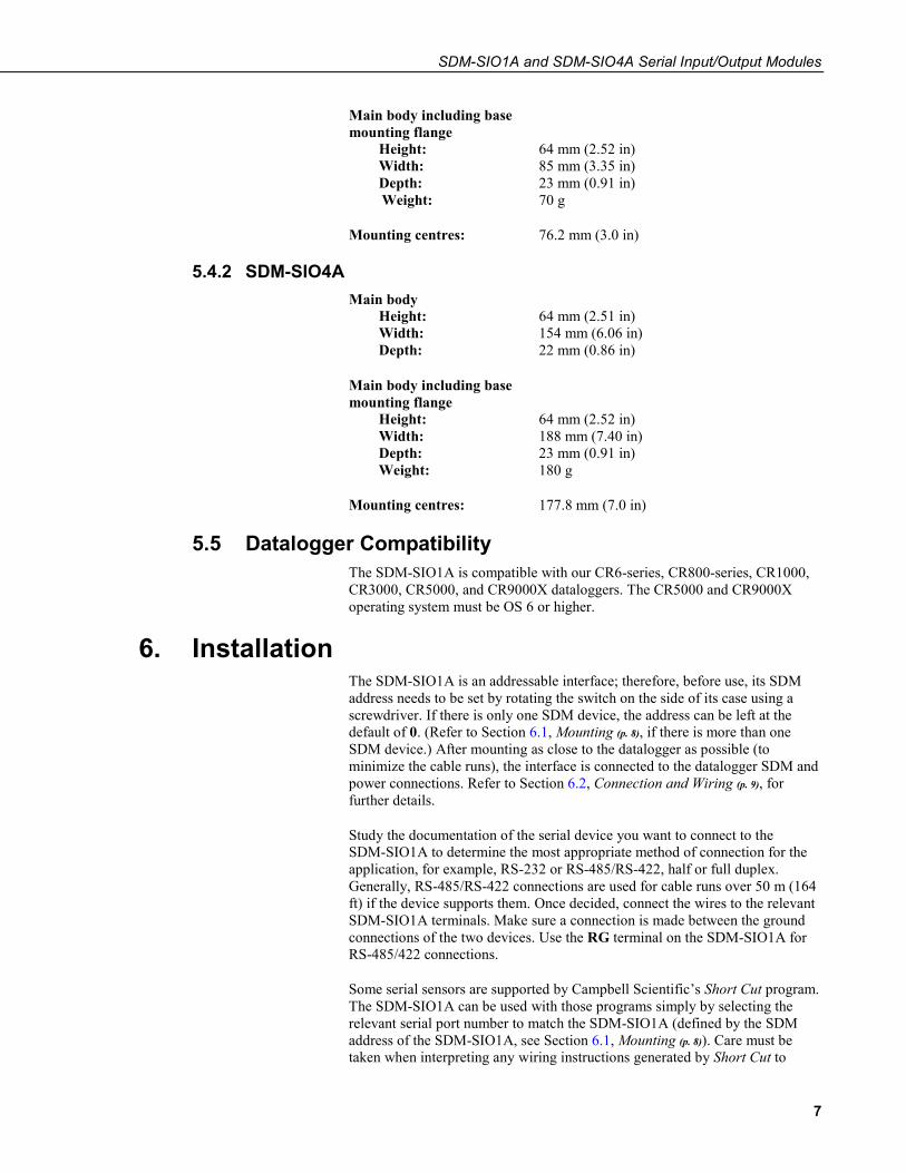
Main body including base mounting flange
Height: 64 mm (2.52 in) Width: 85 mm (3.35 in) Depth: 23 mm (0.91 in)
70 g
76.2 mm (3.0 in)
5.4.2 SDM-SIO4A
Weight:
Mounting centres:
Main body Height: 64 mm (2.51 in) Width: 154 mm (6.06 in) Depth: 22 mm (0.86 in)
Main body including base mounting flange
Height: 64 mm (2.52 in) Width: 188 mm (7.40 in) Depth: 23 mm (0.91 in) Weight: 180 g
Mounting centres: 177.8 mm (7.0 in)
5.5 Datalogger Compatibility The SDM-SIO1A is compatible with our CR6-series, CR800-series, CR1000, CR3000, CR5000, and CR9000X dataloggers. The CR5000 and CR9000X operating system must be OS 6 or higher.
6. InstallationThe SDM-SIO1A is an addressable interface; therefore, before use, its SDM address needs to be set by rotating the switch on the side of its case using a screwdriver. If there is only one SDM device, the address can be left at the default of 0. (Refer to Section 6.1, Mounting (p. 8), if there is more than one SDM device.) After mounting as close to the datalogger as possible (to minimize the cable runs), the interface is connected to the datalogger SDM and power connections. Refer to Section 6.2, Connection and Wiring (p. 9), for further details.
Study the documentation of the serial device you want to connect to the SDM-SIO1A to determine the most appropriate method of connection for the application, for example, RS-232 or RS-485/RS-422, half or full duplex. Generally, RS-485/RS-422 connections are used for cable runs over 50 m (164 ft) if the device supports them. Once decided, connect the wires to the relevant SDM-SIO1A terminals. Make sure a connection is made between the ground connections of the two devices. Use the RG terminal on the SDM-SIO1A for RS-485/422 connections.
Some serial sensors are supported by Campbell Scientific’s Short Cut program. The SDM-SIO1A can be used with those programs simply by selecting the relevant serial port number to match the SDM-SIO1A (defined by the SDM address of the SDM-SIO1A, see Section 6.1, Mounting (p. 8)). Care must be taken when interpreting any wiring instructions generated by Short Cut to

SDM-SIO1A and SDM-SIO4A Serial Input/Output Modules
8
account for the differences in wiring a sensor to the SDM-SIO1A rather than directly to the datalogger.
For other sensors or more complex applications, a CRBasic program needs to be written to configure and enable the connection between the two devices.
To write a program, it is first necessary to determine how data will be exchanged. When using the SDM-SIO1A to collect data from a sensor, there are two options. The datalogger requests data and then picks up the data in the response from the sensor (often called polling) or the sensor transmits data “one-way” to the datalogger at fixed intervals based upon its internal timer. The latter mode is more common but can lead to problems with synchronizing the sensor measurements with other measurements the datalogger is making and can also lead to the occasional missed data value if the sensor clock is running slightly slower than the datalogger clock.
The SDM-SIO1A is implemented in such a way that it looks like a built-in serial port to the user when writing programs in CRBasic. The only difference in operation between the SDM-SIO1A and a built-in port is that there will be a small delay as the data needs to be transferred from the SDM-SIO1A to the datalogger via the SDM port. That delay is usually only significant if large amounts of data are being read or the datalogger program needs to run very fast.
For sending and receiving data, the SerialOpen() instruction is used to specify which serial port, the speed, and mode of operation. The speed is set by the BaudRate parameter in the instruction and the mode (bits, parity, duplex, RS-232 or RS-485) is set by the SerialOpenFormat parameter. Refer to the CRBasic Editor help system for more details of the options. With the correct parameters in the SerialOpen() instruction, the program can be written in almost exactly the same way as using any other serial port with SerialIn(), SerialOut(), and similar instructions. Section 6.3, Programming (p. 16), of this manual gives details of some of the minor changes needed and some simple program examples.
The SDM-SIO1A can also be used as an interface to Modbus and DNP3 sensors or networks. The interface is configured by including an extra SerialOpen() instruction at the start of the program. Normal calls to the relevant Modbus or DNP3 instructions can then be used specifying the COM port number relevant to the SDM-SIO1A.
6.1 Mounting The SDM-SIO1A is normally mounted on the backplate of a Campbell Scientific enclosure using the screws and plastic inserts provided. The SDM-SIO1A is designed to be installed in a dry, non-condensing environment.
Before mounting, select and set the SDM address as this requires access to the side of the case. The SDM address is set with a screwdriver. TABLE 6-1 lists the possible SDM addresses and their relationships to the COMPort parameter in the SerialOpen() instruction.
There can be up to 15 SDM-SIO1As on a single SDM bus. Each SDM-SIO1A will need to be set to a unique address before they are powered. If any other equipment is present on the bus, whether an SDM-SIO1A or other SDM device, the user will have to ensure their addresses are unique.

SDM-SIO1A and SDM-SIO4A Serial Input/Output Modules
9
The SDM-SIO4A has a single address switch. This sets the address of the first serial port of the module (port 1). Other ports have their own SDM address which follow sequentially from the port 1 address. For example, if the address switch is set to 4, port 1 has SDM address 4, port 2 has SDM address 5, port 3 has SDM address 6, and port 4 has SDM address 7. The equivalent ComPort number of each port corresponds to the SDM address of the port in the same way as for the SDM-SIO1A as shown in TABLE 6-1.
For the SDM-SIO4A, if the address switch is set to “C” (SDM 12) or above, only the ports which would have valid SDM addresses are enabled. For example, if the switch is set to “E” (14), only port 1 could be used as sequential addresses above that are not valid.
TABLE 6-1. SDM Address Settings
Rotary Switch Position SDM Address
SerialOpen() Instruction COMPort Number
0 0 32
1 1 33
2 2 34
3 3 35
4 4 36
5 5 37
6 6 38
7 7 39
8 8 40
9 9 41
A 10 42
B 11 43
C 12 44
D 13 45
E 14 46
F1 151 471 1 Address F is not available as it is the broadcast address. Setting this address will result in the SDM-SIO1A having an address of 0 rather than F.
6.2 Connection and Wiring Connection to the SDM-SIO1A is achieved via the 11 terminals arranged along the top of the unit. The terminals are spring loaded providing an easy and reliable method of connection. Strip wires 7 to 9 mm and twist. Open the clamp by pushing the orange tab down with the tip of a small flat-blade screwdriver and insert the wire into the round hole. Release the clamp and verify the clamp grips the wire rather than the plastic insulation.

SDM-SIO1A and SDM-SIO4A Serial Input/Output Modules
10
If there is a need to insert more than one wire in each terminal, if using multi-strand wire, twist the conductors together first. If using solid wires, solder or crimp multiple pairs together before insertion.
TABLE 6-2 shows all the connections on the SDM-SIO1A.
TABLE 6-2. SDM-SIO1A Terminal Labels and Functions
Power SDM Communications Connections
12V
G
C1
C2
C3
RG
G
RTS
/TD
+
Tx/
TD–
Rx/
RD
+
CTS
/RD
–
1 2 3 4 5 6 7 8 9 10 11
TABLE 6-3. SDM-SIO1A Functional Description of the Connections
Pin Case Text Connection To Description
1 12V
Datalogger
Power supply +12V
2 G Power supply 0V (same as other G pin)
3 C1 SDM data enable line
4 C2 SDM clock line
5 C3 SDM data line
6 RG1
Equipment
RG – RS-485 ground. Connected to G via 100 Ω 1 W resistor.
7 G2 0V – (same as other G pin)
8 RTS/TD+ RS-232 RTS. RS-485 half duplex non-inverting. RS-485 full duplex outgoing.
9 Tx/TD– RS-232 transmit. RS-485 half duplex inverting. RS-485 full duplex outgoing.
10 Rx/RD+ RS-232 receive. RS-485 receiver non-inverting. RS-485 full duplex incoming.
11 CTS/RD– RS-232 CTS. RS-485 receiver inverting. RS-485 full duplex incoming.
1 Connection RG (pin 6) has a 100 Ω resistor in series with the datalogger ground connection. This connection should be used when connecting RS-485 equipment by long wire lengths. It ensures both systems have a common ground reference point. See Section 2, Precautions (p. 2), before connecting. 2 The G (pin 7) can be used for the RS-232 zero volt reference or any other ground connection needed, for example, shields.
The SDM-SIO4A has identical wiring for the datalogger connections (pins 1 to 5). To allow for the extra serial ports, pins 6 to 11 are reproduced four times, once for each port. The connections for different ports are clearly delimited, with each labelled with the port number as a single large digit, that is, 1, 2, 3, 4.

SDM-SIO1A and SDM-SIO4A Serial Input/Output Modules
11
The port connections RG, G, RTS/TD+, Tx/TD–, Rx/RD+, and CTS/RD– are labelled exactly the same for each port and match those of the SDM-SIO1A (see TABLE 6-3).
In the examples below, the SDM-SIO4A is wired identically for the datalogger and the serial devices.
As shown above in TABLE 6-3, connections 1 to 5 need to be made to the datalogger, either connecting the SDM lines to the matching control ports or the dedicated SDM port available on some dataloggers, such as the CR3000.
When connecting multiple SDM devices to a datalogger, the SDM connections can either be all connected by separate wires back to the datalogger terminals or, as is common if the SDM devices are mounted in a row in an enclosure, jumper wires can be used to daisy-chain the same terminals on each interface together (including power and ground) with one set of wires running back to the datalogger. It is important to keep the total length of SDM wiring as short as possible.
The connection of the wires to the remote serial device will vary with type of device and method of communication. It is necessary to work out the best mode of operation of the serial device, taking into consideration issues such as power consumption, cable lengths (RS-485 being better than RS-232 for long cables), synchronization of data collection, etc.
If possible, use screened cable for connecting the SDM-SIO1A to remote sensors or devices. Check the manual of the device for details on where to connect the screen for maximum effectiveness.
RS-422 mode is functionally the same as RS-485 mode except the connection is limited to a point-to-point system. Connections and programming for RS-422 are otherwise identical to full-duplex RS-485.
When operating in RS-232 mode, the SDM-SIO1A also supports hardware handshaking.
Section 6.2.1, Wiring Examples for Connecting the SDM-SIO1A (p. 11), provides examples of different connection schemes for the serial devices. Further discussion of different modes of operation is given in Section 7, Operation (p. 23).
6.2.1 Wiring Examples for Connecting the SDM-SIO1A The exact method of wiring the SDM-SIO1A varies with the type of device it is going to exchange data with. The variables include the type of interface used (RS-232, RS-485, or RS-422), whether handshaking is used, whether the connection is full or half duplex, and whether termination resistors are used (RS-485 and RS-422 only).
Typical wiring for the most common configurations are given as examples in the following subsections.
NOTE

SDM-SIO1A and SDM-SIO4A Serial Input/Output Modules
12
6.2.1.1 RS-485/RS-422 Full-Duplex, One-to-One Connection Example
6.2.1.2 RS-485 Full-Duplex, Multi-drop Example

SDM-SIO1A and SDM-SIO4A Serial Input/Output Modules
13
As with all RS-485 configurations, the use of termination resistors is optional. They tend not to be required with shorter cable runs and with modern slew-rate-limited driver technology (as used in the SDM-SIO1A).
6.2.1.3 RS-485 Half-Duplex Wiring Example This shows how to connect a single device, but RS-485 half-duplex networks are the most common multi-drop configuration. If wiring for multiple devices, make the three wire connections in parallel, similar to that shown in the full-duplex multi-drop example.
As with all RS-485 configurations, the use of termination resistors is optional. They tend not to be required with shorter cable runs and with modern slew-rate-limited driver technology (as used in the SDM-SIO1A).
NOTE
NOTE

SDM-SIO1A and SDM-SIO4A Serial Input/Output Modules
14
6.2.1.4 RS-232 Wiring Example with Handshaking
DTE DCE * Note CTS and RTS are optional if hardware handshaking is not required. Not connecting the handshaking lines will reduce the overall current consumption of the SDM-SIO1A.
6.2.1.5 RS-232 Basic 3-Wire Example
DTE DCE

SDM-SIO1A and SDM-SIO4A Serial Input/Output Modules
15
6.2.1.6 Connecting a 9-Way Socket to the SDM-SIO1A for RS-232 Devices This configuration may be used if the device is fitted with a standard 9-way D connector as was commonly fitted to PCs for their RS-232 port. You need to check whether the device is configured as a DTE or DCE device and whether it has a male or female connector before making up this cable.
Pin 8
Pin 2
Pin 3
Pin 7
• In RS-232 mode, the main use of the CTS/RD– and RTS/TD+ lines is as RTS/CTS hardware handshaking lines. CTS/RD– should be connected to the remote equipment’s RTS, and RTS/TD+ to its CTS line.
• The CTS/RD– (CTS) and RTS/TD+ (RTS) lines can also be used to trigger external circuitry when not being used in handshaking mode. Note that when using CTS/RD– and RT/TD+ lines as input and output, the voltage levels are ±5V, NOT 0 and 5V.
• CTS/RD– and RTS/TD+ cannot be used as separate input and output when in RS-485 mode.
SDM-SIO1A and SDM-SIO4A Serial Input/Output Modules
16
6.3 Programming The normal serial port instructions such as SerialOpen() and SerialIn() are used with the SDM-SIO1A. Aside from changes to the COMPort and the SerialOpenFormat parameter, a program written for a standard serial port will usually work with the SDM-SIO1A. The main difference to be aware of, when trying to write fast running programs, is the extra delay needed to transfer data from the SDM-SIO1A to the datalogger (roughly equivalent to transferring data over a serial link at 38 kilobaud).
The following section gives further information about the CRBasic programming language and how the serial instructions are to be used with the SDM-SIO1A.
This section assumes the user has knowledge of the CRBasic programming language. A useful introduction to programming for serial sensors can be found here:
https://s.campbellsci.com/documents/sp/technical-papers/serial.pdf
Please contact Campbell Scientific for further assistance or training. Campbell Scientific’s user forum is also a useful resource to check if others might have already written code for a specific serial device.
Only the parameters that need special explanation or whose functionality has changed when used with the SDM-SIO1A are listed below. Any other parameters should be taken as not having changed. Please refer to the datalogger manual and/or the CRBasic Editor help system for more guidance.
6.3.1 CRBasic Instructions 6.3.1.1 SerialOpen()
All internal buffers in the SDM-SIO1A will be flushed when this instruction is called, resulting in the loss of any data that might have been in them at that point in time.
• COMPort The COMPort numbers are defined in TABLE 6-1, SDM Address Settings (p. 9). COM port numbers in the range of 32 to 47 are reserved for use with the SDM-SIO1A.
• BaudRate BaudRate is used to set up the SDM-SIO1A baud rate as you would with any RS-232 interface. The SDM-SIO1A does not support automatic baud rate recognition. Instead, setting the rate to a negative number sets the automatic flow control system (RTS/CTS). This system is discussed in greater detail in Section 7.1.1, Using RTS/CTS and Automatic Handshaking (p. 23).
• SerialOpenFormat This parameter sets the data format. It also determines whether the SDM-SIO1A works in normal RS-232, listen-only RS-232, full-duplex RS-485, or half-duplex RS-485 mode as defined in the tables below.

SDM-SIO1A and SDM-SIO4A Serial Input/Output Modules
17
TABLE 6-4. Communications Port Parameters RS-232
SerialOpenFormat Parity No. Stop Bits No. Data Bits 0 None 1 8 1 Odd 1 8 2 Even 1 8
3 (default) None 1 8 4 Not used 5 Odd 2 8 6 Even 2 8 7 None 2 8 8 Not used 9 Odd 1 7
10 Even 1 7 111 None 1 7 12 Not used 13 Odd 2 7 14 Even 2 7 15 None 2 7
1 This mode is only supported if there is at least a one-bit delay between characters received by the SDM-SIO1A.
TABLE 6-5. Communications Port Parameters RS-485 Full Duplex
SerialOpenFormat Parity No. Stop Bits No. Data Bits 16 None 1 8 17 Odd 1 8 18 Even 1 8 19 None 1 8 20 Not used 21 Odd 2 8 22 Even 2 8 23 None 2 8 24 Not used 25 Odd 1 7 26 Even 1 7 271 None 1 7 28 Not used 29 Odd 2 7 30 Even 2 7 31 None 2 7
1 This mode is only supported if there is at least a one-bit delay between characters received by the SDM-SIO1A.

SDM-SIO1A and SDM-SIO4A Serial Input/Output Modules
18
TABLE 6-6. Communications Port Parameters RS-485 Half Duplex
SerialOpenFormat Parity No. Stop Bits No. Data Bits 48 None 1 8 49 Odd 1 8 50 Even 1 8 51 None 1 8 52 Not used 53 Odd 2 8 54 Even 2 8 55 None 2 8 56 Not used 57 Odd 1 7 58 Even 1 7 591 None 1 7 60 Not used 61 Odd 2 7 62 Even 2 7 63 None 2 7
1 This mode is only supported if there is at least a one-bit delay between characters received by the SDM-SIO1A.
TABLE 6-7. Communications Port Parameters RS-232 Receive-Only Mode
SerialOpenFormat Parity No. Stop Bits No. Data Bits 64 None 1 8 65 Odd 1 8 66 Even 1 8 67 None 1 8 68 Not used 69 Odd 2 8 70 Even 2 8 71 None 2 8 72 Not used 73 Odd 1 7 74 Even 1 7 751 None 1 7 76 Not used 77 Odd 2 7 78 Even 2 7 79 None 2 7
1 This mode is only supported if there is at least a one-bit delay between characters received by the SDM-SIO1A.

SDM-SIO1A and SDM-SIO4A Serial Input/Output Modules
19
6.3.1.2 SerialClose() This will place the SDM-SIO1A unit into shutdown mode where only SDM communications will operate. This means any data coming into the SDM-SIO1A on the RS-232/RS-485 interface will be lost.
This is the lowest possible power mode, and for optimum power efficiency, the SDM-SIO1A should be placed in this mode whenever possible.
6.3.1.3 SerialIn() The primary difference when using this instruction with an SDM-SIO1A compared to when it is used with a serial port built into the datalogger is timing. If the data has already been sent by the remote sensor/system, the instruction will run in a few tens of microseconds as the data is read from internal memory. However, when using the SDM-SIO1A, extra time is required to transfer data from the module into the datalogger’s own memory.
The extra time (in microseconds) taken to transfer data from the SDM-SIO1A to the datalogger can be calculated using the formula below:
Time = (C + 1) • (8 • SDMRate)
Where,
C = Number of characters to transfer from the SDM-SIO1A
SDMRate = Rate set using the SDMSpeed() instruction in CRBasic giving the time in microseconds for one bit period.
It’s worth noting that the bit rate defined by SDMSpeed() is not exact and will vary slightly depending on the datalogger used. If you require more accurate information about SDM data rates, consult your datalogger documentation.
Example
The instruction SerialIn(Dest,32,1,0,10) using a 30µs bit rate would transfer its 10 bytes of data from the SDM-SIO1A to the datalogger in approximately 2.7 ms.
Time (in microseconds) = (10 + 1) • (8 • 30)
Note that 30 µs per bit is the default data rate for most Campbell Scientific dataloggers. It is possible to reduce this time and the transfer time by using the SDMSpeed() instruction. This can be done if using short cable runs between the datalogger and all SDM devices.
6.3.1.4 SerialOut() Transmission from the SDM-SIO1A will commence once the first byte of user information is received from the datalogger. There will be a total delay of 16 bit periods (at the SDMSpeed()) before transmission commences. Normally this delay can be ignored as it is short (0.48 ms), but some applications may need to account for it.

SDM-SIO1A and SDM-SIO4A Serial Input/Output Modules
20
6.3.1.5 SerialInBlock The SerialInBlock() instruction can be used as described in the datalogger manual. However, if using the option to capture only the most recent data, make sure the instruction is called often enough to avoid filling up the SDM-SIO1A buffer. The SDM-SIO1A buffer operates in fill and stop mode, and, therefore, will not include the most recent data if it gets full.
6.3.1.6 SerialOutBlock No special information. Can also be used to set the general purpose output line. See Appendix A, Using the Handshaking Lines for General Input/Output (p. A-1), for more information.
6.3.1.7 SerialInChk This returns the number of characters that have been received by the SDM-SIO1A and that are currently held in its buffer (0-6143).
6.3.1.8 SerialInRecord No special information.
6.3.1.9 SerialFlush This instruction will purge all information in the datalogger and SDM-SIO1A transmit and receive buffers.
6.3.2 Example Datalogger Programs There follows two simple examples of how to write programs in CRBasic to send and receive data using the SDM-SIO1A. These programs are not extensive and are fundamentally no different to those written for use when reading data from a standard datalogger serial port.
The program code is the same for all dataloggers that support the SDM-SIO1A.
The exact program to be used will vary with the serial device being used. Unfortunately, the number of possible variations of reading different sensors is almost infinite. If you are struggling to write code, please contact Campbell Scientific who may already have experience with the sensor and may be able to offer advice on how to deal with it.

SDM-SIO1A and SDM-SIO4A Serial Input/Output Modules
21
6.3.2.1 Example using RS-232 Mode
CRBasic Example 6-1. RS-232 Mode Example
'----------------------------------------------------------------------- ' Example use of the SDM-SIO1A. ' This example shows how to open a serial port using an SDM-SIO1A. ' A prompt is sent from the datalogger to the sensor and it then waits for a response ' before reading the data. ' The datalogger then retrieves the data and places it into a string '----------------------------------------------------------------------- Public ReturnedData as string * 100 'string where the data from the datalogger is stored BeginProg Const SensorPort = 32 'Declare the serial port the sensor is set to 'The sensors address switch should be set to position 0 SDMSpeed (30) 'Optionally set the SDMSpeed - not normally needed Scan(1000,mSec,0,0) 'Open serial port to RS-232 mode, 115200bps, 8-bit data, 1 stop bit, and no parity SerialOpen (SensorPort,115200,3,100,10000) 'open the serial port to the sensor 'Request data' will need to be replaced with the correct command for your sensor 'In this example we wait for the response ‘Start’ for up to 1 second before continuing SerialOut (SensorPort,"Request data","Start",1,100) 'Send data to the sensor SerialIn (ReturnedData,SensorPort,100,0,100) 'Get data from the sensor SerialClose (SensorPort) 'Close the serial port to the sensor 'this places the SDM-SIO1A into its lowest power mode 'Now there would be code to read the data out of the ReturnedData string and either store 'it as strings or convert the string into number(s). Next Scan EndProg
SDM-SIO1A and SDM-SIO4A Serial Input/Output Modules
22
6.3.2.2 Example using RS-485 Mode
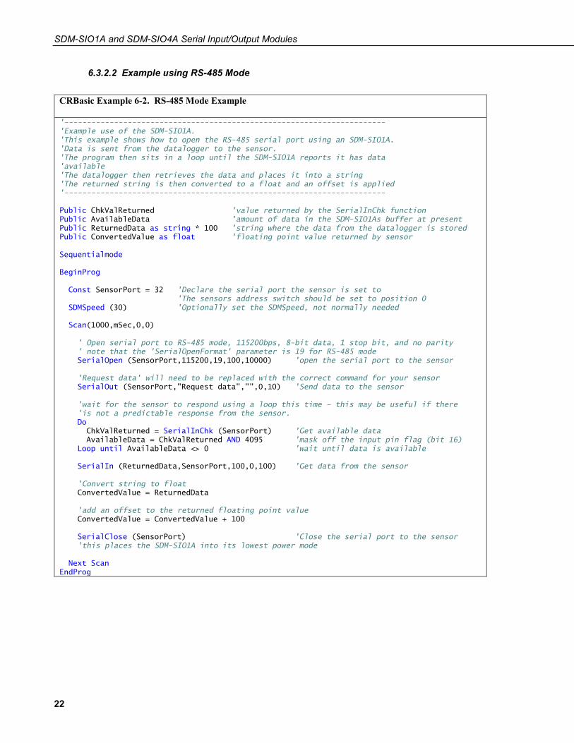
CRBasic Example 6-2. RS-485 Mode Example
'----------------------------------------------------------------------- 'Example use of the SDM-SIO1A. 'This example shows how to open the RS-485 serial port using an SDM-SIO1A. 'Data is sent from the datalogger to the sensor. 'The program then sits in a loop until the SDM-SIO1A reports it has data 'available 'The datalogger then retrieves the data and places it into a string 'The returned string is then converted to a float and an offset is applied '----------------------------------------------------------------------- Public ChkValReturned 'value returned by the SerialInChk function Public AvailableData 'amount of data in the SDM-SIO1As buffer at present Public ReturnedData as string * 100 'string where the data from the datalogger is stored Public ConvertedValue as float 'floating point value returned by sensor Sequentialmode BeginProg Const SensorPort = 32 'Declare the serial port the sensor is set to 'The sensors address switch should be set to position 0 SDMSpeed (30) 'Optionally set the SDMSpeed, not normally needed Scan(1000,mSec,0,0) ' Open serial port to RS-485 mode, 115200bps, 8-bit data, 1 stop bit, and no parity ' note that the 'SerialOpenFormat' parameter is 19 for RS-485 mode SerialOpen (SensorPort,115200,19,100,10000) 'open the serial port to the sensor 'Request data' will need to be replaced with the correct command for your sensor SerialOut (SensorPort,"Request data","",0,10) 'Send data to the sensor 'wait for the sensor to respond using a loop this time – this may be useful if there 'is not a predictable response from the sensor. Do ChkValReturned = SerialInChk (SensorPort) 'Get available data AvailableData = ChkValReturned AND 4095 'mask off the input pin flag (bit 16) Loop until AvailableData <> 0 'wait until data is available SerialIn (ReturnedData,SensorPort,100,0,100) 'Get data from the sensor 'Convert string to float ConvertedValue = ReturnedData 'add an offset to the returned floating point value ConvertedValue = ConvertedValue + 100 SerialClose (SensorPort) 'Close the serial port to the sensor 'this places the SDM-SIO1A into its lowest power mode Next Scan EndProg

SDM-SIO1A and SDM-SIO4A Serial Input/Output Modules
23
7. Operation This section includes more detail on less common modes of operation, provides details on how to save power use, and shows the internal configuration of the SDM-SIO1A when configured in RS-485 or RS-422 full-duplex mode.
7.1 Configuring Handshaking and Receive-Only Modes 7.1.1 Using RTS/CTS and Automatic Handshaking
Handshaking is a method used by RS-232 to ensure communications equipment is free to receive or transmit data. This interface is often called RTS/CTS (hardware handshaking) or DTR/DTE.
Automatic handshaking for the SDM-SIO1A is activated through use of the BaudRate parameter of the SerialOpen() instruction.. When the BaudRate value is set to a negative number, the SDM-SIO1A will enable automatic handshaking. It is worth noting that normally setting the BaudRate to a negative number will enable automatic baud rate detection; this is not the case for the SDM-SIO1A.
When enabled, the two I/O ports (pins 8 and 11) will operate as RTS and CTS lines. It is important that the remote equipment supports handshaking as no data will be sent if handshaking is enabled but is not supported by the equipment the SDM-SIO1A is connected to.
Once handshaking is enabled, pins 8 and 11 are no longer available for general use and are dedicated to the auto-handshaking system.
Enabling handshaking will increase active current consumption due to the extra RS-232 load. It will not affect sleep current, however, as the RS-232 chip is disabled (sleep is set by calling the SerialClose() function).
For connection diagrams and further information on using handshaking, consult Section 6.2.1, Wiring Examples for Connecting the SDM-SIO1A (p. 11).
• Auto flow control should only be selected in RS-232 mode.
• When Auto flow control is enabled, the user cannot set or clear the spare I/O ports (pins 8 and 11).
7.1.2 RS-485 Half-Duplex Mode In RS-485 half-duplex mode, the SDM-SIO1A will wait for approximately 2.5 ms after a character is received before it tries to transmit any data in its transmit buffer. This is to ensure that a contention does not occur on the data line which will cause data corruption. There is also a delay of at least the time to send one character after the last character has been transmitted before the SDM-SIO1A will listen for new incoming data.
When in either RS-485 half-duplex or full-duplex modes, the user cannot set or clear the spare I/O ports (pins 8 and 11).
NOTE
NOTE

SDM-SIO1A and SDM-SIO4A Serial Input/Output Modules
24
7.1.3 Using the RS-232 Link in Receive-Only Mode To place the SDM-SIO1A into RS-232 receive-only mode, use the SerialOpen() instruction with the SerialOpenFormat value set within the range of 64 to 79. Consult Section 6.3.1.1, SerialOpen (p. 16), for more detailed information about these settings.
In receive-only mode, the SDM-SIO1A will consume less current than normal but still can receive new information on its RS-232 port.
The example below will set the SDM-SIO1A with address 0 into receive-only mode. All normal baud rates and buffer sizes are supported.
Example
SerialOpen (32,115200,64,100,10000) ‘Set receive only mode
7.2 Power Conservation The SDM-SIO1A features an industry-standard RS-232/RS-485 driver chipset to ensure maximum likelihood of compatibility with all other devices. When the driver is powered on, it uses more power than one of the datalogger control-port-based COM ports — typically 6 mA minimum. This is partly because it generates the correct signal levels, which in itself requires power, and partly because, in the case of RS-232 signals, the resting state of ~ –6 V driving a nominal RS-232 ~3 k load implicitly wastes ~2 mA of current per line.
To avoid excess current waste, the chip can be turned off when not in use, for example, between polled measurements, simply by closing the serial port, using SerialClose() (see Section 6.3.1.2, SerialClose (p. 19)). When running in RS-232 mode with a sensor that only sends data one way to the datalogger, run the SDM-SIO1A in “receive-only mode” as this does not turn on the output drivers (see Section 7.1.3, Using the RS-232 Link in Receive-Only Mode (p. 24)).
If using RS-232 mode, also avoid connecting handshaking lines that are not required to avoid an unnecessary 2 mA drain per line.
The SDM-SIO1A will start up with its last set of baud rate and protocol settings. This feature is to protect against brownout conditions where the SDM-SIO1A has reset but the datalogger has not. It does, however, mean that the SDM-SIO1A does not start up in its lowest power mode. To place the SDM-SIO1A into its lowest power mode, you will need to run the SerialClose() instruction.
7.3 Schematic FIGURE 7-1 shows the internal configuration of the SDM-SIO1A when configured in RS-485 or RS-422 full-duplex mode. This shows the internal resistors to aid users trying to test system interconnections and drive levels.

SDM-SIO1A and SDM-SIO4A Serial Input/Output Modules
25
FIGURE 7-1. RS-485 Internal Circuit Diagram
RG is for connecting the screen/ground of the data lines when in RS-485 mode; there is a 1 W 100 Ω resistor in series designed to limit any currents that may be induced due to a difference in ground potentials between the sensor and the SDM-SIO1A.
8. Troubleshooting and Maintenance 8.1 Troubleshooting
If correctly connected, the SDM-SIO1A normally operates seamlessly. However, there are some common issues people encounter during setup or sometimes after a period of operation.
During the setup phase, either no data or corrupt data may be received by the datalogger. When receiving data, the character “?” will be returned in place of the expected data whenever a parity, framing, or overrun error is detected. These errors are only flagged for RS-232/RS-485/RS-422 data coming into the SDM-SIO1A.
These types of errors are usually caused by a connection issue or sometimes a mismatch of the interface type, baud rate, or data format (parity, etc.).
SDM-SIO1A and SDM-SIO4A Serial Input/Output Modules
26
Some confusion can be caused in debugging such problems because it is possible for the communication to partly work even with such mismatches, for instance:
• Mismatched parity settings will often show many valid charactersinterspersed with invalid characters or “?” which the SDM-SIO1Awill store if there are parity errors.
• Incorrect connections resulting in inverted signals can also result insome valid characters being received, but usually with no normal data.
• An RS-485 receiver can often read data transmitted at RS-232 levels,although the reverse will not work.
Where you see some serial activity which is invalid, check the documentation and configuration of both the device the SDM-SIO1A is connected to and the datalogger. Also, check the wiring carefully.
In the case of RS-485/RS-422, there is also a big risk of confusion being caused by there being several different ways of labelling the transmit and receive lines. Some devices may even have reversed meaning for some lines—for example, A and B are sometimes used and transposed. Generally, for these lines it is safe to try swapping them around if there is doubt as to whether the same terminology is being used.
If you are sure the configuration and wiring of the datalogger and serial device is correct, it is possible to check what the datalogger thinks it is transmitting and the data it is receiving by connecting to the datalogger with a computer and entering the terminal mode. You can then use the “W” command to “sniff” data passing to and fro through any serial port including SDM-SIO1A ports. The data can be displayed in ASCII or binary (HEX) modes. This is a powerful tool for checking programming errors and the response of remote devices. See the datalogger manual for more information on terminal mode.
Either during setup or at some point later, it is possible that erratic communication errors may be seen. The normal cause of this will be noise pickup, especially for long cable runs. The likelihood of such errors can be reduced by using screened cable, making sure there is a ground connection between the two systems, and installing termination resistors for RS-485/ RS-422 links. It is worth noting that textbooks often say termination resistors are only needed for long cables at very high baud rates, which is true when considering noise caused by reflections. However, even a single termination resistor at one end of the link can suppress induced noise caused by pickup from other sources such as nearby mains cables. As a general rule, if you have a noise issue, it is worth trying to add a cheap 100-120 Ω resistor across RS-485 lines.
8.2 Maintenance No regular maintenance is needed for the SDM-SIO1A; however, occasionally operating system upgrades are released to add enhanced features or to correct bugs. The operating system is normally published in the Support section of our website at www.campbellsci.com.

SDM-SIO1A and SDM-SIO4A Serial Input/Output Modules
27
8.2.1 Upgrading the Operating System In the unlikely event that the operating system of the SDM-SIO1A needs to be upgraded, this can be achieved by connecting it to a PC and using the Campbell Scientific Device Configuration Utility (DevConfig) to load the operating system. (This program can be downloaded free of charge from www.campbellsci.com/downloads).
The SDM-SIO1A needs a reliable source of 12V power connected in the standard way. It also requires a cable similar to that shown in Section 6.2.1.6, Connecting a 9-Way Socket to the SDM-SIO1A for RS-232 Devices (p. 15), to connect to an RS-232 port on the PC. However, there is no requirement to connect any handshaking lines.
Start DevConfig and select the SDM-SIO1A device. (The SDM-SIO1A device may not be available in older versions of the software. New versions can be downloaded from the Campbell Scientific website at www.campbellsci.com.) Follow the instructions for that device to load a new operating system. At the end of the process, a success message will be shown if successful. During the loading of the operating system, do not disturb or disconnect power to the SDM-SIO1A, otherwise it may need to be returned to the factory for repair.
When following this process with the SDM-SIO4A, it is necessary to run this process four times, connecting to each serial port in turn. This is because each serial port has its own microprocessor with each holding their own copy of the operating system.
8.2.2 Operating System Signature Errors The operating system is stored in flash memory. When a new version is loaded, a checksum signature is automatically created the first time its run. This checksum is stored in memory. This signature value can be read back using the datalogger and compared to the signature supplied with the operating system version that was just loaded (contact Campbell Scientific if you need to do this).
If the SDM-SIO1A is not operational or is exhibiting random faults, the flash memory may be corrupted. This is a very unlikely event due to the robust nature of the flash device used. The unit automatically checks the flash memory against its signature upon power up. If an error is found, it will send out the string sig error:XXXX:YYYY when an error is detected, where XXXX is the signature as it’s being read and YYYY is the stored signature.
The error string is sent out via the RS-232 port automatically and will also be returned to the datalogger the next time any attempt is made to read information from the sensor. The message will be output at the default baud rate of 9600 bps, 8-bits, 1 stop, and no parity.
If this error is seen, contact Campbell Scientific to obtain a copy of the latest operating system and load it into the SDM-SIO1A using the above procedure. If this does not correct the fault, the unit may be faulty and will need to be returned to the factory for repair.
SDM-SIO1A and SDM-SIO4A Serial Input/Output Modules
28
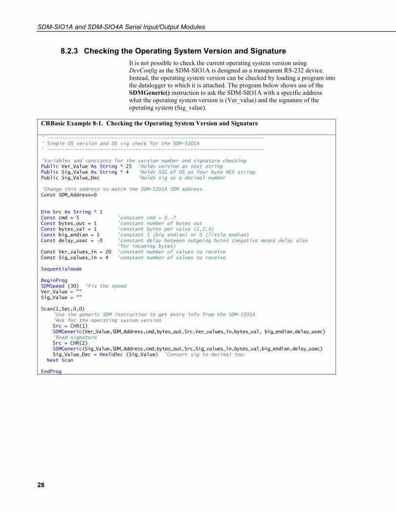
8.2.3 Checking the Operating System Version and Signature It is not possible to check the current operating system version using DevConfig as the SDM-SIO1A is designed as a transparent RS-232 device. Instead, the operating system version can be checked by loading a program into the datalogger to which it is attached. The program below shows use of the SDMGeneric() instruction to ask the SDM-SIO1A with a specific address what the operating system version is (Ver_value) and the signature of the operating system (Sig_value).
CRBasic Example 8-1. Checking the Operating System Version and Signature
' -------------------------------------------------------------------------- ' Simple OS version and OS sig check for the SDM-SIO1A ' -------------------------------------------------------------------------- 'Variables and constants for the version number and signature checking Public Ver_Value As String * 25 'Holds version as text string Public Sig_Value As String * 4 'Holds SIG of OS as four byte HEX string Public Sig_Value_Dec 'Holds sig as a decimal number 'Change this address to match the SDM-SIO1A SDM address. Const SDM_Address=0 Dim Src As String * 1 Const cmd = 5 'constant cmd = 0..7 Const bytes_out = 1 'constant number of bytes out Const bytes_val = 1 'constant bytes per value (1,2,4) Const big_endian = 1 'constant 1 (big endian) or 0 (little endian) Const delay_usec = -0 'constant delay between outgoing bytes (negative means delay also 'for incoming bytes) Const Ver_values_in = 20 'constant number of values to receive Const Sig_values_in = 4 'constant number of values to receive Sequentialmode BeginProg SDMSpeed (30) 'Fix the speed Ver_Value = "" Sig_Value = "" Scan(1,Sec,0,0) 'Use the generic SDM instruction to get extra info from the SDM-SIO1A 'Ask for the operating system version Src = CHR(1) SDMGeneric(Ver_Value,SDM_Address,cmd,bytes_out,Src,Ver_values_in,bytes_val, big_endian,delay_usec) 'Read signature Src = CHR(2) SDMGeneric(Sig_Value,SDM_Address,cmd,bytes_out,Src,Sig_values_in,bytes_val,big_endian,delay_usec) Sig_Value_Dec = HexToDec (Sig_Value) 'Convert sig to decimal too. Next Scan EndProg

A-1
Appendix A. Using the Handshaking Lines for General Input/Output This appendix describes how to use the CTS and RTS lines for input and output ports.
The I/O pins (CTS/pin 11 and RTS/pin 8) can be read or set by the user as required, allowing unique protocols to be created, or they can simply be used as flags or enable lines.
If the user enables automatic handshaking as discussed in Section 7.1.1, Using RTS/CTS and Automatic Handshaking (p. 23), pins 8 and 11 cannot be accessed.
A.1 The Input Pin (CTS/Pin 11) The state of the input line (pin 11) can be read by using the special SDMGeneric() instruction in CRBasic.
Bit 16 of a value returned to the datalogger using the SDMGeneric() instruction reports whether the input is logic high or low. The example below shows how to call the instruction with the required parameters.
CRBasic Example A-1. Detecting the State of the Input Line
'CR1000 Example program showing how to detect the state of the input line on an SDM-SIO1A 'Using the SDMGeneric instruction Public sio1response As Long, Inputstate As Boolean Const addr = 0 'constant sdm address CHANGE with SDM-SIO1A address Const cmd = 1 'constant, command 1 returns the input state in bit 16 Const bytes_out = 0 'constant number of bytes out - none sent Const bytes_val = 2 'two bytes returned Const big_endian = 1 '1=(big endian) Const delay_usec = -0 'delay between outgoing bytes (negative means delay also for incoming bytes) Const Values_in = 1 'Main Program BeginProg Scan (1,Sec,0,0) 'Or whatever scan rate is being used 'Use the SDMGeneric instruction to send command 0x01 which returns the input line state as bit 16 SDMGeneric(sio1response,addr,cmd,bytes_out,"",Values_in,bytes_val, big_endian,delay_usec) 'bit 16 set for input line high or low so check the value and set a Boolean var TRUE or FALSE accordingly Inputstate = sio1response AND &H8000 NextScan EndProg
The input line can accept 0 and 5V logic inputs OR –12 and +12V RS-232 level inputs. Below is a breakdown of the different input voltages allowed and the state of the input line flag.
Voltage on the input line State of bit 16
+12V 1
–12V 0
5V 1
0V 0
Appendix A. Using the Handshaking Lines for General Input/Output
A-2
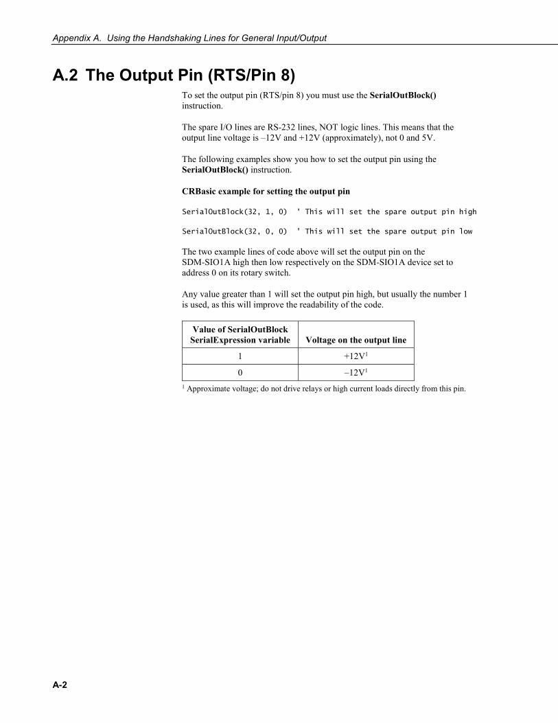
A.2 The Output Pin (RTS/Pin 8) To set the output pin (RTS/pin 8) you must use the SerialOutBlock() instruction.
The spare I/O lines are RS-232 lines, NOT logic lines. This means that the output line voltage is –12V and +12V (approximately), not 0 and 5V.
The following examples show you how to set the output pin using the SerialOutBlock() instruction.
CRBasic example for setting the output pin
SerialOutBlock(32, 1, 0) ' This will set the spare output pin high
SerialOutBlock(32, 0, 0) ' This will set the spare output pin low
The two example lines of code above will set the output pin on the SDM-SIO1A high then low respectively on the SDM-SIO1A device set to address 0 on its rotary switch.
Any value greater than 1 will set the output pin high, but usually the number 1 is used, as this will improve the readability of the code.
Value of SerialOutBlock SerialExpression variable Voltage on the output line
1 +12V1
0 –12V1 1 Approximate voltage; do not drive relays or high current loads directly from this pin.

B-1
Appendix B. Matching SDM-SIO1A Connections to an SDM-SIO1
This section is provided for users who are familiar with the older SDM-SIO1, so they can cross reference connections between the new and old devices.
The SDM-SIO1A has fewer terminals and different labelling than the SDM-SIO1. It does, however, perform in exactly the same way and can be used as a drop-in substitute with only minor changes to the wiring. It has fewer terminals because the Z, Y, B, and A terminals are not present. For the SDM-SIO1 these terminals were connected internally to the Tx, RTS, CTS and Rx terminals respectively and were, therefore, duplicates. RS-422 and RS-485 devices can be connected to the equivalent multifunction terminals on the SDM-SIO1A.
The labelling for the RS-422/RS-485 functions has also been changed to avoid the confusion caused by different labelling conventions used for the A and B terminals by different manufacturers. To avoid this, the SDM-SIO1A uses the alternative TD–, TD+, RD–, RD+ scheme of labelling, with the TD– and TD+ pair being those used for RS-485 half-duplex connections. Please refer to TABLE B-1 for a cross comparison between the connections for the SDM-SIO1 and the SDM-SIO1A.
TABLE B-1. Pin Cross Connection Table for SDM-SIO1 to SDM-SIO1A
SDM-SIO1 SDM-SIO1A
Case Text Pin Pin Case Text
C1 1 3 C1
C2 2 4 C2
C3 3 5 C3
G 4 2 G
+12V 5 1 +12V
G 6 7 G
RX-A 7 10 Rx/RD+
CTS-B 8 11 CTS/RD–
RTS-Y 9 8 RTS/TD+
TX-Z 10 9 Tx/TD–
0V 11 6 RG
Z 12 9 Tx/TD–
Y 13 8 RTS/TD+
B 14 11 CTS/RD–
A 15 10 Rx/RD+


Campbell Scientific Companies
Campbell Scientific, Inc. 815 West 1800 North Logan, Utah 84321 UNITED STATES
www.campbellsci.com • [email protected]
Campbell Scientific Africa Pty. Ltd. PO Box 2450
Somerset West 7129 SOUTH AFRICA
www.campbellsci.co.za • [email protected]
Campbell Scientific Southeast Asia Co., Ltd. 877/22 Nirvana@Work, Rama 9 Road
Suan Luang Subdistrict, Suan Luang District Bangkok 10250
THAILAND www.campbellsci.asia • [email protected]
Campbell Scientific Australia Pty. Ltd. PO Box 8108
Garbutt Post Shop QLD 4814 AUSTRALIA
www.campbellsci.com.au • [email protected]
Campbell Scientific (Beijing) Co., Ltd. 8B16, Floor 8 Tower B, Hanwei Plaza
7 Guanghua Road Chaoyang, Beijing 100004
P.R. CHINA www.campbellsci.com • [email protected]
Campbell Scientific do Brasil Ltda. Rua Apinagés, nbr. 2018 Perdizes CEP: 01258-00 São Paulo SP
BRASIL www.campbellsci.com.br • [email protected]
Campbell Scientific Canada Corp. 14532 – 131 Avenue NW Edmonton AB T5L 4X4
CANADA www.campbellsci.ca • [email protected]
Campbell Scientific Centro Caribe S.A. 300 N Cementerio, Edificio Breller
Santo Domingo, Heredia 40305 COSTA RICA
www.campbellsci.cc • [email protected]
Campbell Scientific Ltd. Campbell Park
80 Hathern Road Shepshed, Loughborough LE12 9GX
UNITED KINGDOM www.campbellsci.co.uk • [email protected]
Campbell Scientific Ltd. 3 Avenue de la Division Leclerc
92160 ANTONY FRANCE
www.campbellsci.fr • [email protected]
Campbell Scientific Ltd. Fahrenheitstraße 13
28359 Bremen GERMANY
www.campbellsci.de • [email protected]
Campbell Scientific Spain, S. L. Avda. Pompeu Fabra 7-9, local 1
08024 Barcelona SPAIN
www.campbellsci.es • [email protected]
Please visit www.campbellsci.com to obtain contact information for your local US or international representative.