windows server 2012 r2 nic teaming (lbfo) deployment and management.docx
TRANSCRIPT
User Guide for NIC Teaming (LBFO)A Guide to Windows Server 2012 R2 NIC Teaming for the novice and the expert.
1 NIC TeamingNIC teaming, also known as Load Balancing/Failover (LBFO), allows multiple network adapters to be placed into a team for the purposes of
bandwidth aggregation, and/or traffic failover to maintain connectivity in the event of a network component failure.
This feature has long been available from NIC vendors but until Windows Server 2012 NIC teaming was not included with Windows Server.
The following sections address:
NIC teaming architecture Bandwidth aggregation (also known as load balancing) mechanisms Failover algorithms NIC feature support – stateless task offloads and more complex NIC functionality A detailed walkthrough how to use the NIC Teaming management tools
NIC teaming is available in Windows Server 2012 R2 in all editions, both ServerCore and full Server versions. NIC teaming is not available in Windows 8.1, however the NIC teaming User Interface and the NIC Teaming Windows PowerShell Cmdlets can both be run on Windows 8.1 so that a Windows 8.1 PC can be used to manage teaming on one or more Windows Server 2012 R2 servers or Windows Server 2012 servers or a combination thereof.
Bluetooth®, Infiniband®, and other trademarks throughout this document are the property of their respective owners. Hyper-V® and Windows® are trademarks of Microsoft Corporation.
2 Contents, Figures, Tables, and Glossary
2.1 Table of Contents1 NIC Teaming........................................................................................................................... 1
2 Contents, Figures, Tables, and Glossary.................................................................................2
2.1 Table of Contents............................................................................................................2
2.2 List of Tables....................................................................................................................4
2.3 List of Figures.................................................................................................................. 4
2.4 Glossary...........................................................................................................................5
3 Technical Overview.................................................................................................................7
3.1 Traditional architectures for NIC teaming.......................................................................7
3.2 Configurations for NIC Teaming......................................................................................7
3.3 Algorithms for load distribution......................................................................................9
3.4 Interactions between Configurations and Load distribution algorithms.......................11
3.4.1 Switch Independent configuration / Address Hash distribution............................11
3.4.2 Switch Independent configuration / Hyper-V Port distribution.............................11
3.4.3 Switch Independent configuration / Dynamic distribution....................................12
3.4.4 Switch Dependent configuration / Address Hash distribution...............................12
3.4.5 Switch Dependent configuration / Hyper-V Port distribution................................12
3.4.6 Switch Dependent configuration / Dynamic distribution.......................................13
3.5 NIC teaming inside of Virtual Machines (VMs)..............................................................14
3.6 Hyper-V ports in the Host Partition...............................................................................15
3.7 Feature compatibilities..................................................................................................15
3.7.1 NIC Teaming and Virtual Machine Queues (VMQs)...............................................17
3.7.2 Hyper-V Network Virtualization (HNV) / NV-GRE compatibility.............................18
3.8 NIC Requirements and limitations.................................................................................19
3.8.1 Number of NICs in a team in a native host.............................................................19
3.8.2 Number of NICs in a team in a Hyper-V VM...........................................................19
3.8.3 Types of NICs in a team..........................................................................................19
2
3.8.4 Number of team interfaces for a team..................................................................19
3.9 Teaming of different speed NICs...................................................................................19
3.10 Teams of teams.............................................................................................................20
3.11 MAC address use and management..............................................................................20
3.12 Industry terms for NIC Teaming....................................................................................20
3.13 Troubleshooting (The dangers of using a powerful tool)..............................................21
3.13.1 Using VLANs...........................................................................................................21
3.13.2 Interactions with other teaming solutions.............................................................23
3.13.3 MAC address conflicts............................................................................................23
3.13.4 Physical network segmentation.............................................................................24
3.13.5 Hardware that doesn’t conform to specification...................................................24
3.13.6 Physical switch security features............................................................................24
3.13.7 Disabling and Enabling with Windows PowerShell.................................................24
4 Managing NIC Teaming.........................................................................................................25
4.1 Invoking the Management UI for NIC Teaming.............................................................26
4.2 The components of the NIC Teaming Management UI.................................................28
4.3 Adding a server to be managed.....................................................................................30
4.4 Removing a server from the managed servers list........................................................31
4.5 Creating a team.............................................................................................................31
4.6 Checking the status of a team.......................................................................................34
4.7 Modifying a team..........................................................................................................35
4.7.1 Modifying a team through the UI...........................................................................35
4.7.2 Modifying a team through Windows PowerShell...................................................37
4.7.3 Adding new interfaces to the team........................................................................40
4.7.4 Modifying team interfaces.....................................................................................41
4.7.5 Removing interfaces from the team......................................................................44
4.8 Deleting a team.............................................................................................................44
4.9 Viewing statistics for a team or team member.............................................................45
4.9.1 Viewing statistics for a team interface...................................................................45
4.9.2 Setting frequency of Statistics updates..................................................................46
3
5 NIC Teaming differences between Windows Server 2012 R2 and Windows Server 2012....47
6 Frequently asked questions (FAQs)......................................................................................48
7 Power User tips for the NIC Teaming User Interface............................................................50
2.2 List of TablesTable 1 - Feature interactions with NIC teaming.........................................................................16Table 2 - VMQ mode by Teaming mode and Load distribution mode.........................................17
2.3 List of FiguresFigure 1 - Standard NIC teaming solution architecture and Microsoft vocabulary........................7Figure 3 - NIC Teaming in a VM with SR-IOV with two VFs..........................................................13Figure 4 - Enabling VM NIC Teaming in Hyper-V Manager...........................................................15Figure 5 - VLAN misconfiguration................................................................................................22Figure 6 – NIC Teaming Windows PowerShell Cmdlets...............................................................26Figure 7 - PowerShell Get-Help....................................................................................................26Figure 8 - Invoking the UI from Server Manager Local Server screen..........................................26Figure 9- Invoking the UI from Server Manager All Servers screen..............................................27Figure 10- Invoking the UI from a Windows PowerShell prompt.................................................28Figure 11- Invoking the UI from a Command Prompt..................................................................28Figure 12 - the NIC Teaming Management UI tiles......................................................................29Figure 13 - Column Chooser menus.............................................................................................29Figure 14 – Tasks menus and Right-click action menus...............................................................30Figure 15 - Team Interfaces Tasks and Right-click Action Menu..................................................30Figure 16 - New Team dialog box.................................................................................................32Figure 17 - New Team dialog box with Additional Properties expanded.....................................33Figure 18 - Team with a faulted member....................................................................................35Figure 19 - Modifying Team Properties........................................................................................36Figure 20 - Modifying a team's Teaming mode, Load distribution mode, and Standby Adapter.37Figure 21 - Selecting Add Interface..............................................................................................40Figure 22 - New team interface dialog box..................................................................................40Figure 23 - Team Interface tab after creating new team interface..............................................41Figure 24 - Selecting a team interface to change the VLAN ID.....................................................42Figure 25- Network Adapter Properties dialog box for team interfaces......................................43Figure 26 - Deleting a team..........................................................................................................44Figure 27- Statistics information for teams and team members.................................................45Figure 28- Statistics information for teams and team interfaces.................................................46
4
Figure 29 - General settings dialog box........................................................................................47
2.4 GlossarySome terms and acronyms used in this document may not be familiar to the reader. The following table should assist the reader’s understanding. See also Section 3.12.
Term/Acronym Definition or Expansion
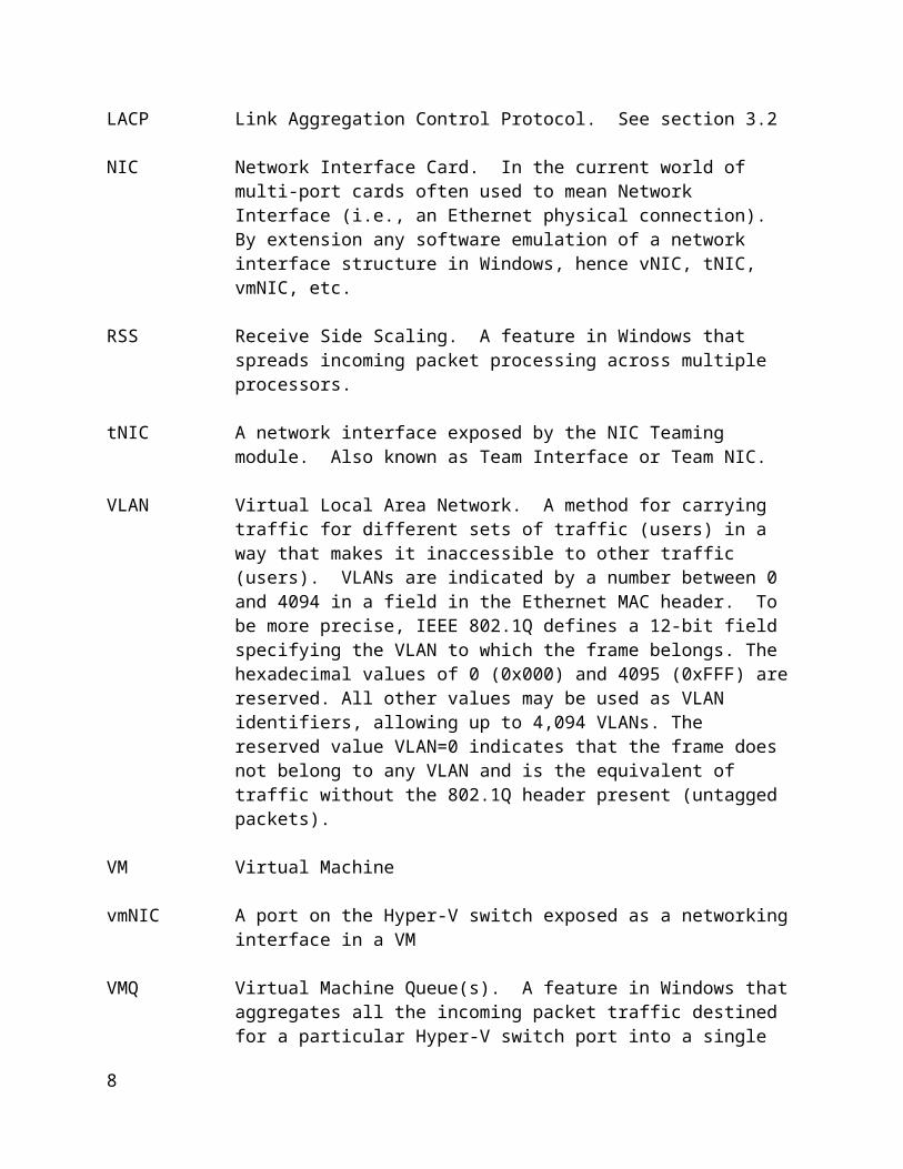
LACP Link Aggregation Control Protocol. See section 3.2
NIC Network Interface Card. In the current world of multi-port cards often used to mean Network Interface (i.e., an Ethernet physical connection). By extension any software emulation of a network interface structure in Windows, hence vNIC, tNIC, vmNIC, etc.
RSS Receive Side Scaling. A feature in Windows that spreads incoming packet processing across multiple processors.
tNIC A network interface exposed by the NIC Teaming module. Also known as Team Interface or Team NIC.
VLAN Virtual Local Area Network. A method for carrying traffic for different sets of traffic (users) in a way that makes it inaccessible to other traffic (users). VLANs are indicated by a number between 0 and 4094 in a field in the Ethernet MAC header. To be more precise, IEEE 802.1Q defines a 12-bit field specifying the VLAN to which the frame belongs. The hexadecimal values of 0 (0x000) and 4095 (0xFFF) are reserved. All other values may be used as VLAN identifiers, allowing up to 4,094 VLANs. The reserved value VLAN=0 indicates that the frame does not belong to any VLAN and is the equivalent of traffic without the 802.1Q header present (untagged packets).
VM Virtual Machine
vmNIC A port on the Hyper-V switch exposed as a networking interface in a VM
VMQ Virtual Machine Queue(s). A feature in Windows that aggregates all the incoming packet traffic destined for a particular Hyper-V switch port into a single queue and associates the processing of that queue to a specific processor. This provides workload distribution across processors in a Hyper-V host.
vNIC A port on the Hyper-V switch exposed as a networking interface in the host partition
5
6

3 Technical Overview
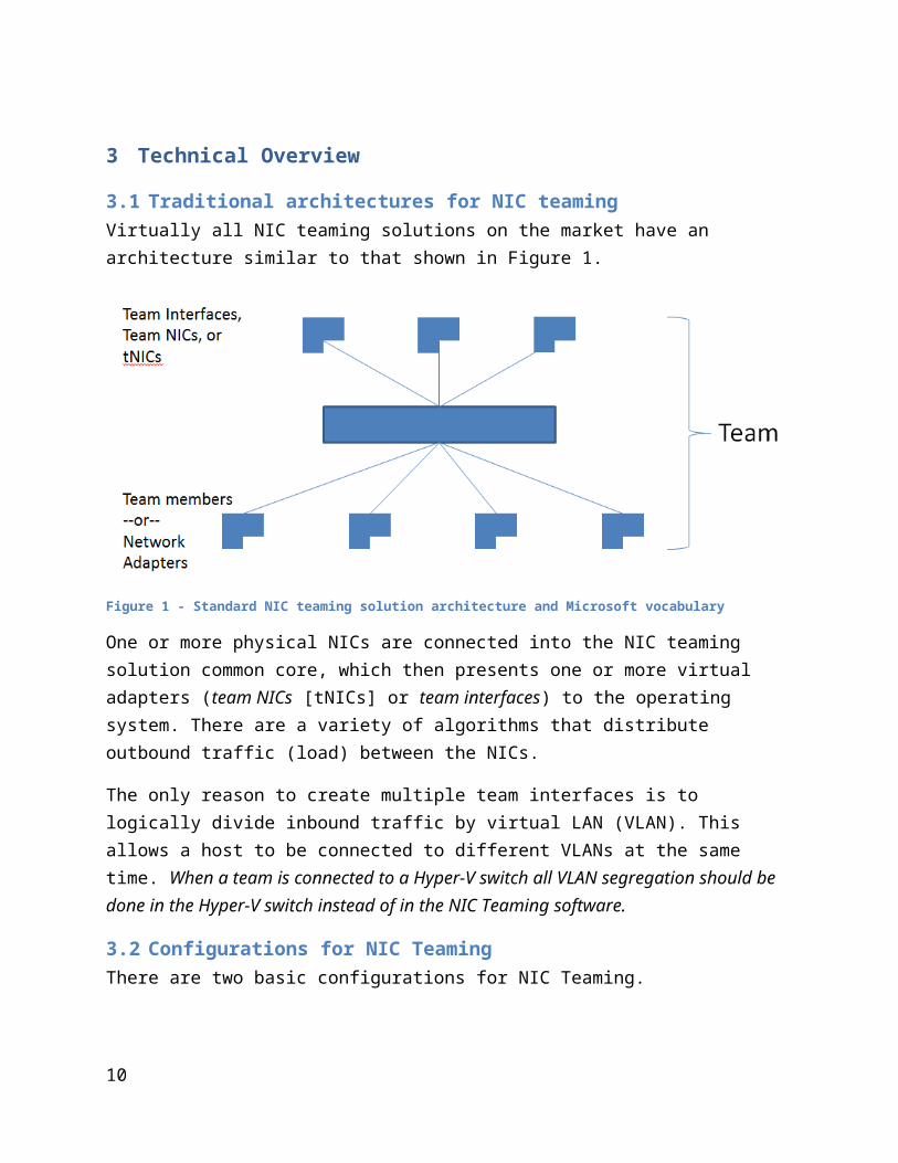
3.1 Traditional architectures for NIC teamingVirtually all NIC teaming solutions on the market have an architecture similar to that shown in Figure 1.
Figure 1 - Standard NIC teaming solution architecture and Microsoft vocabulary
One or more physical NICs are connected into the NIC teaming solution common core, which then presents one or more virtual adapters (team NICs [tNICs] or team interfaces) to the operating system. There are a variety of algorithms that distribute outbound traffic (load) between the NICs.
The only reason to create multiple team interfaces is to logically divide inbound traffic by virtual LAN (VLAN). This allows a host to be connected to different VLANs at the same time. When a team is connected to a Hyper-V switch all VLAN segregation should be done in the Hyper-V switch instead of in the NIC Teaming software.
3.2 Configurations for NIC TeamingThere are two basic configurations for NIC Teaming.
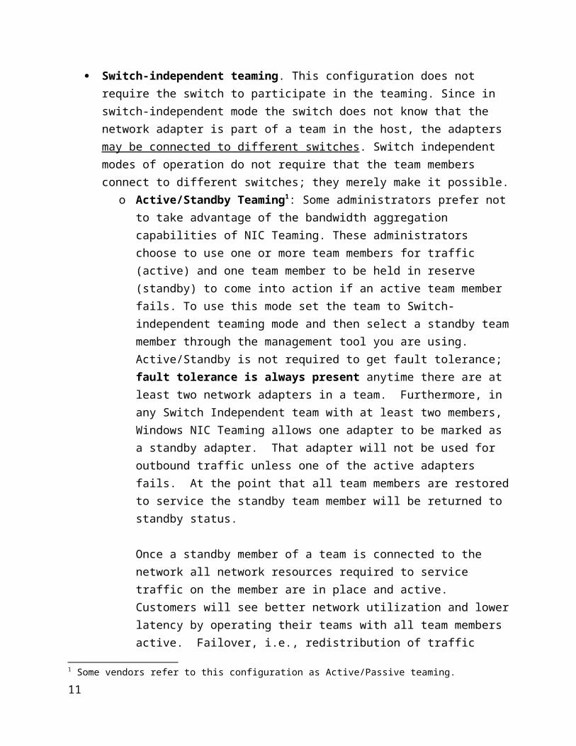
Switch-independent teaming. This configuration does not require the switch to participate in the teaming. Since in switch-independent mode the switch does not know that the network adapter is part of a team in the host, the adapters may be connected to different switches. Switch independent modes of operation do not require that the team members connect to different switches; they merely make it possible.
7
o Active/Standby Teaming1: Some administrators prefer not to take advantage of the bandwidth aggregation capabilities of NIC Teaming. These administrators choose to use one or more team members for traffic (active) and one team member to be held in reserve (standby) to come into action if an active team member fails. To use this mode set the team to Switch-independent teaming mode and then select a standby team member through the management tool you are using. Active/Standby is not required to get fault tolerance; fault tolerance is always present anytime there are at least two network adapters in a team. Furthermore, in any Switch Independent team with at least two members, Windows NIC Teaming allows one adapter to be marked as a standby adapter. That adapter will not be used for outbound traffic unless one of the active adapters fails. At the point that all team members are restored to service the standby team member will be returned to standby status.
Once a standby member of a team is connected to the network all network resources required to service traffic on the member are in place and active. Customers will see better network utilization and lower latency by operating their teams with all team members active. Failover, i.e., redistribution of traffic across the remaining healthy team members, will occur anytime one or more of the team members reports an error state exists.
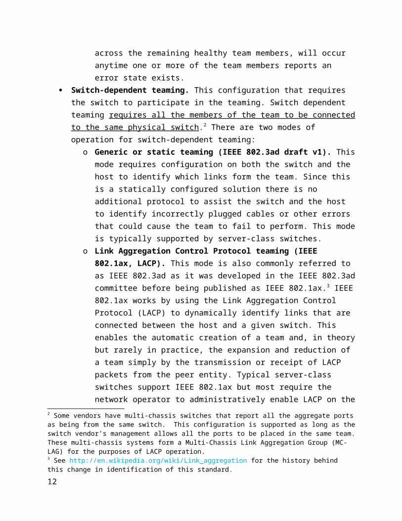
Switch-dependent teaming. This configuration that requires the switch to participate in the teaming. Switch dependent teaming requires all the members of the team to be connected to the same physical switch.2 There are two modes of operation for switch-dependent teaming:
o Generic or static teaming (IEEE 802.3ad draft v1). This mode requires configuration on both the switch and the host to identify which links form the team. Since this is a statically configured solution there is no additional protocol to assist the switch and the host to identify incorrectly plugged cables or other errors that could cause the team to fail to perform. This mode is typically supported by server-class switches.
o Link Aggregation Control Protocol teaming (IEEE 802.1ax, LACP). This mode is also commonly referred to as IEEE 802.3ad as it was developed in the IEEE 802.3ad committee before being published as IEEE 802.1ax.3 IEEE 802.1ax works by using the Link Aggregation Control Protocol (LACP) to dynamically identify
1 Some vendors refer to this configuration as Active/Passive teaming.2 Some vendors have multi-chassis switches that report all the aggregate ports as being from the same switch. This configuration is supported as long as the switch vendor’s management allows all the ports to be placed in the same team. These multi-chassis systems form a Multi-Chassis Link Aggregation Group (MC-LAG) for the purposes of LACP operation.
8

links that are connected between the host and a given switch. This enables the automatic creation of a team and, in theory but rarely in practice, the expansion and reduction of a team simply by the transmission or receipt of LACP packets from the peer entity. Typical server-class switches support IEEE 802.1ax but most require the network operator to administratively enable LACP on the port.4 Windows NIC Teaming always operates in LACP’s Active mode with a short timer. No option is presently available to modify the timer or change the LACP mode.
Both of these modes allow both inbound and outbound traffic to approach the practical limits of the aggregated bandwidth because the pool of team members is seen as a single pipe.
Because the switch determines the inbound load distribution it is important to research what options may be available for inbound load distribution management. Many switches only use destination IP address to team member mapping which may result in a less granular distribution than is needed to get good inbound load distribution. Since this guide can’t cover all the settings on all switches it remains an exercise for the reader to understand the capabilities of the adjacent network switches.
3.3 Algorithms for load distributionOutbound traffic can be distributed among the available links in many ways. One rule that guides any distribution algorithm is to try to keep all packets associated with a single flow (TCP-stream) on a single network adapter. This rule minimizes performance degradation caused by reassembling out-of-order TCP segments.
NIC teaming in Windows Server 2012 R2 supports the following traffic load distribution algorithms:
Hyper-V switch port. Since VMs have independent MAC addresses, the VM’s MAC address or the port it’s connected to on the Hyper-V switch can be the basis for dividing traffic. There is an advantage in using this scheme in virtualization. Because the adjacent switch always sees a particular MAC address on one and only one connected port, the switch will distribute the ingress load (the traffic from the switch to the host) on multiple links based on the destination MAC (VM MAC) address. This is particularly useful when Virtual Machine Queues (VMQs) are used as a queue can be placed on the specific NIC where the traffic is expected to arrive. However, if the host has only a few
3 See http://en.wikipedia.org/wiki/Link_aggregation for the history behind this change in identification of this standard.4 There are security challenges to allowing completely dynamic IEEE 802.1ax operation on a switch. As a result, switches today still require the switch administrator to configure the switch ports that are allowed to be members of such a team.
9
VMs, this mode may not be granular enough to get a well-balanced distribution. This mode will also always limit a single VM (i.e., the traffic from a single switch port) to the bandwidth available on a single interface. Windows Server 2012 R2 uses the Hyper-V Switch Port as the identifier rather than the source MAC address as, in some instances, a VM may be using more than one MAC address on a switch port.
Address Hashing. This algorithm creates a hash based on address components of the packet and then assigns packets that have that hash value to one of the available adapters. Usually this mechanism alone is sufficient to create a reasonable balance across the available adapters.
The components that can be specified, using PowerShell, as inputs to the hashing function include the following:
o Source and destination TCP ports and source and destination IP addresses (this is used by the user interface when “Address Hash” is selected)
o Source and destination IP addresses onlyo Source and destination MAC addresses only
The TCP ports hash creates the most granular distribution of traffic streams resulting in smaller streams that can be independently moved between members. However, it cannot be used for traffic that is not TCP or UDP-based or where the TCP and UDP ports are hidden from the stack, such as IPsec-protected traffic. In these cases, the hash automatically falls back to the IP address hash or, if the traffic is not IP traffic, to the MAC address hash.
See Section 4.7.2.3 for the PowerShell commands that can switch a team between load distribution modes and a deeper explanation of each hashing mode.
Dynamic. This algorithm takes the best aspects of each of the other two modes and combines them into a single mode.
o Outbound loads are distributed based on a hash of the TCP Ports and IP addresses. Dynamic mode also rebalances loads in real time so that a given outbound flow may move back and forth between team members.
o Inbound loads are distributed as though the Hyper-V port mode was in use. See Section 3.4 for more details.
The outbound loads in this mode are dynamically balanced based on the concept of flowlets. Just as human speech has natural breaks at the ends of words and sentences, TCP flows (TCP communication streams) also have naturally occurring breaks. The portion of a TCP flow between two such breaks is referred to as a flowlet. When the
10
dynamic mode algorithm detects that a flowlet boundary has been encountered, i.e., a break of sufficient length has occurred in the TCP flow, the algorithm will opportunistically rebalance the flow to another team member if apropriate. The algorithm may also periodically rebalance flows that do not contain any flowlets if circumstances require it. As a result the affinity between TCP flow and team member can change at any time as the dynamic balancing algorithm works to balance the workload of the team members.
3.4 Interactions between Configurations and Load distribution algorithms
3.4.1 Switch Independent configuration / Address Hash distributionThis configuration will distribute the load through the use of the selected level of address hashing. It defaults to using TCP ports and IP addresses to seed the hash function.
Because a given IP address can only be associated with a single MAC address for routing purposes, this mode receives inbound traffic on only one team member (the primary member). This means that the inbound traffic cannot exceed the bandwidth of one team member no matter how much is getting sent.
This mode is best used for:a) Active/Standby mode teams with just 2 team members; andb) Teaming in a VM.
In all other cases where this configuration was recommended in Windows Server 2012 the new configuration, Switch Independent/Dynamic, described in section , should provide better performance.
3.4.2 Switch Independent configuration / Hyper-V Port distributionThis configuration will send packets using all active team members distributing the load based on the Hyper-V switch port number. Each Hyper-V port will be bandwidth limited to not more than one team member’s bandwidth because the port is affinitized to exactly one team member at any point in time.
Because each Hyper-V port is associated with a single team member, this mode receives inbound traffic for the VM’s switch port on the same team member the switch port’s outbound traffic uses. This also allows maximum use of Virtual Machine Queues (VMQs) for better performance over all.
In all cases where this configuration was recommended in Windows Server 2012 the new configuration, Switch Independent/Dynamic, described in 3.4.3 , will provide better performance.
11
3.4.3 Switch Independent configuration / Dynamic distributionThis configuration will distribute the load based on the TCP Ports address hash as modified by the Dynamic load balancing algorithm. The Dynamic load balancing algorithm will redistribute flows to optimize team member bandwidth utilization so individual flow transmissions may move from one active team member to another. The algorithm takes into account the small possibility that redistributing traffic could cause out-of-order delivery of packets so it takes steps to minimize that possibility.
The receive side, however, will look identical to Hyper-V Port distribution. Each Hyper-V switch port’s traffic, whether bound for a virtual NIC in a VM (vmNIC) or a virtual NIC in the host (vNIC), will see all its inbound traffic arriving on a single NIC.
This mode is best used for teaming in both native and Hyper-V environments except when:
a) Teaming is being performed in a VM,b) Switch dependent teaming (e.g., LACP) is required by policy, orc) Operation of a two-member Active/Standby team is required by policy.
3.4.4 Switch Dependent configuration / Address Hash distributionThis configuration will distribute the load through the use of the selected level of address hashing. It defaults to using TCP ports and IP addresses to seed the hash function.
Like in all switch dependent configurations, the switch determines how to distribute the inbound traffic among the team members. The switch is expected to do a reasonable job of distributing the traffic across the team members but it has complete independence to determine how it does so.
In all cases where this configuration was recommended in Windows Server 2012 the new configuration, Switch Dependent/Dynamic, described in 3.4.6, will provide better performance. As a result this mode is not a first-choice recommendation for any workload.
3.4.5 Switch Dependent configuration / Hyper-V Port distributionThis configuration will distribute the load based on the Hyper-V switch port number. Each Hyper-V port will be bandwidth limited to not more than one team member’s bandwidth because the port is affinitized to exactly one team member at any point in time.
Like in all switch dependent configurations, the switch determines how to distribute the inbound traffic among the team members. The switch is expected to do a reasonable job of distributing the traffic across the team members but it has complete independence to determine how it does so.
12
In all cases where this configuration was recommended in Windows Server 2012 the new configuration, Switch Dependent/Dynamic, described in 3.4.6, will provide better performance.
3.4.6 Switch Dependent configuration / Dynamic distributionThis configuration will distrubte the load based on the TransportPorts address hash as modified by the dynamic load balancing algorithm. The Dynamic load balancing algorithm will redistribute flows to optimize team member bandwidth utilization so individual flow transmissions may move from one active team member to another. The algorithm takes into account the small possibility that redistributing traffic could cause out-of-order delivery of packets so it takes steps to minimize that possibility.
Like in all switch dependent configurations, the switch determines how to distribute the inbound traffic among the team members. The switch is expected to do a reasonable job of distributing the traffic across the team members but it has complete independence to determine how it does so.
This mode is best used for teaming in all cases where Switch Dependent configurations are required by policy. Depending on the capabilities of the adjacent switch it may also do very well, and perhaps even best, when supporting teaming of native workloads.
3.5 NIC teaming inside of Virtual Machines (VMs)NIC Teaming in a VM only applies to vmNICs connected to external switches; vmNICs connected to internal or private switches will show as disconnected when they are in a team.
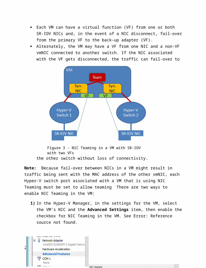
NIC teaming in Windows Server 2012 R2 may also be deployed in a VM. This allows a VM to have virtual NICs connected to more than one Hyper-V switch and still maintain connectivity even if the physical NIC under one switch gets disconnected. This is particularly important when working with Single Root I/O Virtualization (SR-IOV) because SR-IOV traffic doesn’t go through the Hyper-V switch and thus cannot be protected by a team in or under the Hyper-V host. With the VM-teaming option an administrator can set up two Hyper-V switches, each connected to its own SR-IOV-capable NIC.
Each VM can have a virtual function (VF) from one or both SR-IOV NICs and, in the event of a NIC disconnect, fail-over from the primary VF to the back-up adapter (VF).
Alternately, the VM may have a VF from one NIC and a non-VF vmNIC connected to another switch. If the NIC associated with the VF gets disconnected, the traffic can fail-over to the other switch without loss of connectivity.
13
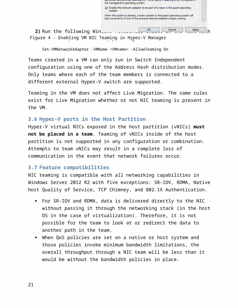
Note: Because fail-over between NICs in a VM might result in traffic being sent with the MAC address of the other vmNIC, each Hyper-V switch port associated with a VM that is using NIC Teaming must be set to allow teaming There are two ways to enable NIC Teaming in the VM:
1) In the Hyper-V Manager, in the settings for the VM, select the VM’s NIC and the Advanced Settings item, then enable the checkbox for NIC Teaming in the VM. See Figure 3.
2) Run the following Windows PowerShell cmdlet in the host with elevated (Administrator) privileges.
Set-VMNetworkAdapter -VMName <VMname> -AllowTeaming On
Teams created in a VM can only run in Switch Independent configuration using one of the Address Hash distribution modes. Only teams where each of the team members is connected to a different external Hyper-V switch are supported.
Teaming in the VM does not affect Live Migration. The same rules exist for Live Migration whether or not NIC teaming is present in the VM.
3.6 Hyper-V ports in the Host PartitionHyper-V virtual NICs exposed in the host partition (vNICs) must not be placed in a team. Teaming of vNICs inside of the host partition is not supported in any configuration or combination. Attempts to team vNICs may result in a complete loss of communication in the event that network failures occur.
14
Figure 3 - Enabling VM NIC Teaming in Hyper-V Manager
3.7 Feature compatibilitiesNIC teaming is compatible with all networking capabilities in Windows Server 2012 R2 with five exceptions: SR-IOV, RDMA, Native host Quality of Service, TCP Chimney, and 802.1X Authentication.
For SR-IOV and RDMA, data is delivered directly to the NIC without passing it through the networking stack (in the host OS in the case of virtualization). Therefore, it is not possible for the team to look at or redirect the data to another path in the team.
When QoS policies are set on a native or host system and those policies invoke minimum bandwidth limitations, the overall throughput through a NIC team will be less than it would be without the bandwidth policies in place.
TCP Chimney is not supported with NIC teaming in Windows Server 2012 R2 since TCP Chimney has the entire networking stack offloaded to the NIC.
802.1X Authentication should not be used with NIC Teaming and some switches will not permit configuration of both 802.1X Authentication and NIC Teaming on the same port.
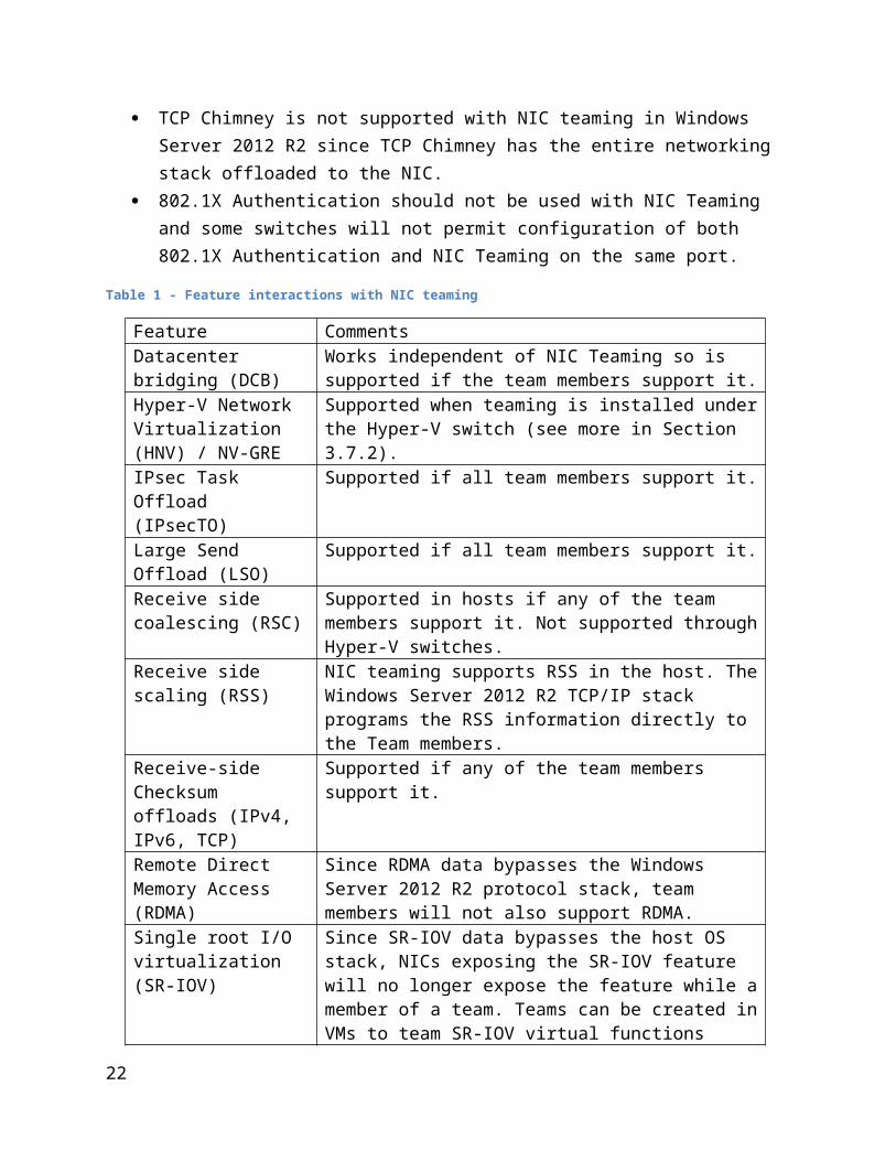
Table 1 - Feature interactions with NIC teaming
Feature CommentsDatacenter bridging (DCB)
Works independent of NIC Teaming so is supported if the team members support it.
Hyper-V Network Virtualization (HNV) / NV-GRE
Supported when teaming is installed under the Hyper-V switch (see more in Section 3.7.2).
IPsec Task Offload (IPsecTO)
Supported if all team members support it.
Large Send Offload (LSO)
Supported if all team members support it.
Receive side coalescing (RSC)
Supported in hosts if any of the team members support it. Not supported through Hyper-V switches.
Receive side scaling (RSS)
NIC teaming supports RSS in the host. The Windows Server 2012 R2 TCP/IP stack programs the RSS information directly to the Team members.
Receive-side Checksum offloads (IPv4, IPv6, TCP)
Supported if any of the team members support it.
Remote Direct Memory Access (RDMA)
Since RDMA data bypasses the Windows Server 2012 R2 protocol stack, team members will not also support RDMA.
Single root I/O virtualization (SR-IOV)
Since SR-IOV data bypasses the host OS stack, NICs exposing the SR-IOV feature will no longer expose the feature while a member of a team. Teams can be created in VMs to team SR-IOV virtual functions (VFs). See also Section 3.5.
15
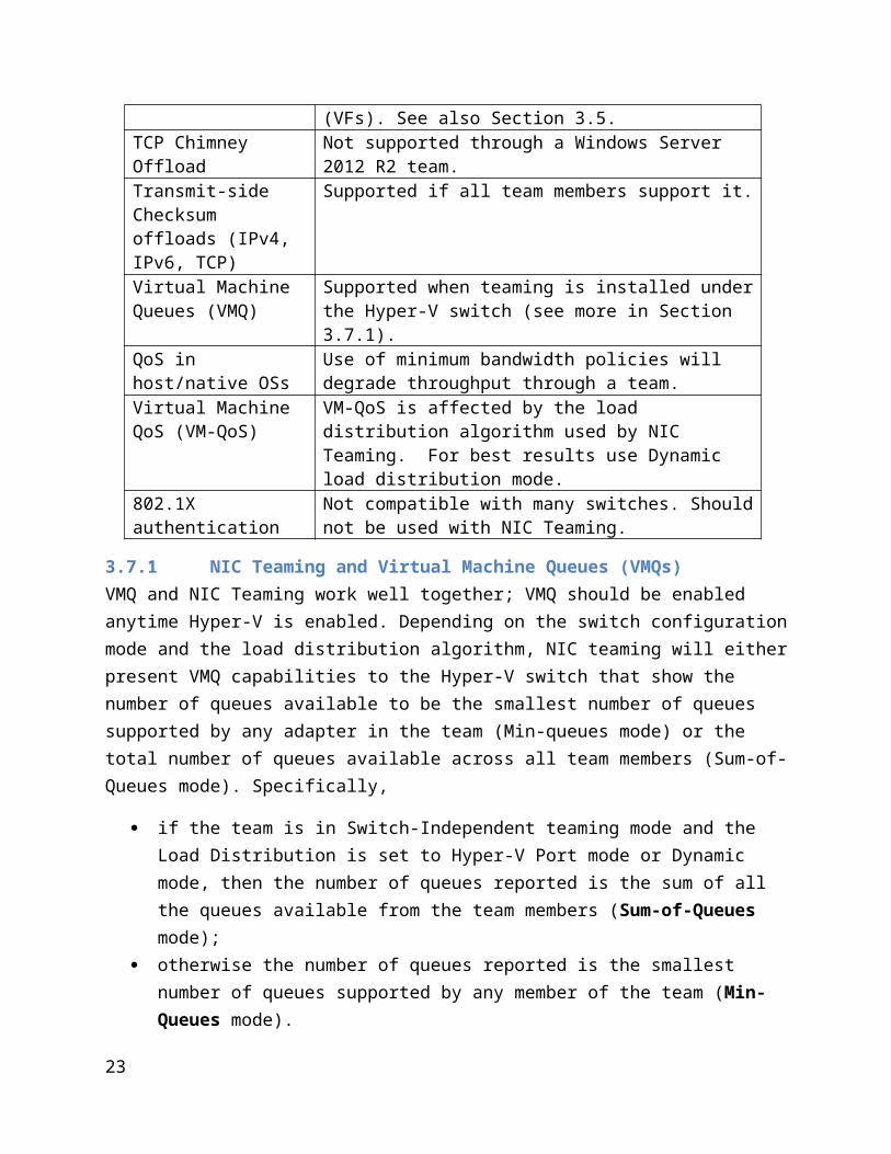
TCP Chimney Offload Not supported through a Windows Server 2012 R2 team.Transmit-side Checksum offloads (IPv4, IPv6, TCP)
Supported if all team members support it.
Virtual Machine Queues (VMQ)
Supported when teaming is installed under the Hyper-V switch (see more in Section 3.7.1).
QoS in host/native OSs Use of minimum bandwidth policies will degrade throughput through a team.
Virtual Machine QoS (VM-QoS)
VM-QoS is affected by the load distribution algorithm used by NIC Teaming. For best results use Dynamic load distribution mode.
802.1X authentication Not compatible with many switches. Should not be used with NIC Teaming.
3.7.1 NIC Teaming and Virtual Machine Queues (VMQs)VMQ and NIC Teaming work well together; VMQ should be enabled anytime Hyper-V is enabled. Depending on the switch configuration mode and the load distribution algorithm, NIC teaming will either present VMQ capabilities to the Hyper-V switch that show the number of queues available to be the smallest number of queues supported by any adapter in the team (Min-queues mode) or the total number of queues available across all team members (Sum-of-Queues mode). Specifically,
if the team is in Switch-Independent teaming mode and the Load Distribution is set to Hyper-V Port mode or Dynamic mode, then the number of queues reported is the sum of all the queues available from the team members (Sum-of-Queues mode);
otherwise the number of queues reported is the smallest number of queues supported by any member of the team (Min-Queues mode).
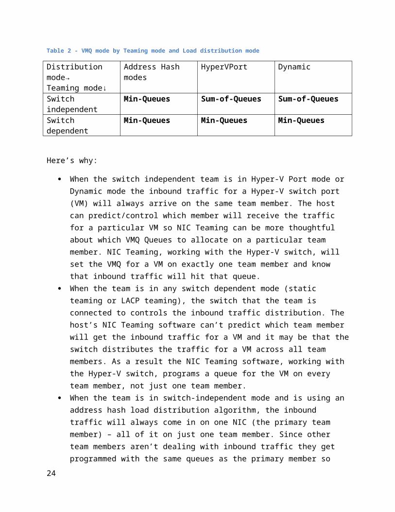
Table 2 - VMQ mode by Teaming mode and Load distribution mode
Distribution mode→Teaming mode↓
Address Hash modes HyperVPort Dynamic
Switch independent Min-Queues Sum-of-Queues Sum-of-QueuesSwitch dependent Min-Queues Min-Queues Min-Queues
Here’s why:
When the switch independent team is in Hyper-V Port mode or Dynamic mode the inbound traffic for a Hyper-V switch port (VM) will always arrive on the same team member. The host can predict/control which member will receive the traffic for a particular VM so NIC Teaming can be more thoughtful about which VMQ Queues to allocate on a particular team member. NIC Teaming, working with the Hyper-V switch,
16
will set the VMQ for a VM on exactly one team member and know that inbound traffic will hit that queue.
When the team is in any switch dependent mode (static teaming or LACP teaming), the switch that the team is connected to controls the inbound traffic distribution. The host’s NIC Teaming software can’t predict which team member will get the inbound traffic for a VM and it may be that the switch distributes the traffic for a VM across all team members. As a result the NIC Teaming software, working with the Hyper-V switch, programs a queue for the VM on every team member, not just one team member.
When the team is in switch-independent mode and is using an address hash load distribution algorithm, the inbound traffic will always come in on one NIC (the primary team member) – all of it on just one team member. Since other team members aren’t dealing with inbound traffic they get programmed with the same queues as the primary member so that if the primary member fails any other team member can be used to pick up the inbound traffic and the queues are already in place.
There are a few VMQ settings that will help the system perform even better. For context keep in mind that most NICs have queues that can be used for either RSS or VMQ but not both at the same time. Hence some VMQ settings appear to be settings for RSS queues but are really settings on the generic queues that both RSS and VMQ use depending on which feature is presently in use.
Each NIC has, in its advanced properties, values for *RssBaseProcNumber and *MaxRssProcessors.
Ideally each NIC should have the *RssBaseProcNumber set to an even number greater than or equal to two (2). This is because the first physical processor, Core 0 (logical processors 0 and 1), typically does most of the system processing so the network processing should be steered away from this physical processor. (Some machine architectures don’t have two logical processors per physical processor so for such machines the base processor should be greater than or equal to 1. If in doubt assume your host is using a 2 logical processor per physical processor architecture.)
If the team is in Sum-of-Queues mode the team members’ processors should be, to the extent practical, non-overlapping. For example, in a 4-core host (8 logical processors) with a team of 2 10Gbps NICs, you could set the first one to use base processor of 2 and to use 4 cores; the second would be set to use base processor 6 and use 2 cores.
If the team is in Min-Queues mode the processor sets used by the team members must be identical.
17
3.7.2 Hyper-V Network Virtualization (HNV) / NV-GRE compatibilityWindows Server 2012 R2 NIC Teaming is fully compatible with Hyper-V Network Virtualization (HNV). The HNV management system provides information to the NIC Teaming driver that allows NIC Teaming to distribute the load in a way that is optimized for the HNV traffic. For further information on this topic see the documentation for HNV.
3.8 NIC Requirements and limitationsFor various reasons not all maximum configuration limits may be achievable at the same time.
3.8.1 Number of NICs in a team in a native host NIC teaming requires the presence of at least one Ethernet NIC. A team of one NIC may be used for separation of traffic using VLANs. Obviously a team with only one team member has no failure protection. Fault protection (failover) requires a minimum of two Ethernet NICs in the team. The Windows Server 2012 R2 implementation supports up to 32 NICs in a team.
3.8.2 Number of NICs in a team in a Hyper-V VM The Windows Server 2012 R2 NIC Teaming solution supports teams with two members in VMs. Larger teams can be created but such teams are not supported. Every team member must be connected to a different external Hyper-V switch and the VM’s networking interfaces must be set to allow teaming.
3.8.3 Types of NICs in a team Any Ethernet NIC that has passed the Windows Hardware Qualification and Logo test (WHQL tests) may be used in a Windows Server 2012 R2 team.
NICs representing technologies other than Ethernet are not supported in teams (e.g., WWAN, WLAN/WiFi, Bluetooth, Infiniband including IPoIB NICs).
Hyper-V vNICs, i.e., Hyper-V switch ports exposed as NICs in the host partition, may not be placed in a team.
The kernel debug network adapter (KDNIC) may not be placed in a team.
NICs that are being used for network boot may not be placed in a team.
3.8.4 Number of team interfaces for a team Windows Server 2012 R2 supports up to 32 team interfaces per team.
3.9 Teaming of different speed NICsTeaming of NICs capable of operating at different speeds but presently operating at the same speed is supported, e.g., a 10 Gbps NIC operating as a 1Gbps NIC may be teamed with another NIC operating at 1Gbps.
18
Teaming of NICs with different speed connections is not supported. The teaming software will allow you to build such a team; however the traffic distribution algorithms in this release do not base the distribution on the speeds of the connections. A team consisting of a 10Gbps NIC and a 100Mbps NIC will send approximately half of the traffic to each NIC.
If you are creating a team where one team member will be active and another will be available to help out if the active team member fails (active/standby mode, see Section 3.2), a lower speed NIC may be used as the standby NIC so that connectivity is maintained.
3.10 Teams of teamsA Team of teams is a team where the team members are actually team interfaces from other teams. This is not supported in the Windows Server 2012 R2 NIC Teaming solution. Furthermore, attempting to place the team interface from a 3rd-party teaming solution into a Microsoft team may result in an unstable system that may lose connectivity to the network. DO NOT mix elements of 3rd-party teaming solutions with elements of Microsoft’s NIC Teaming solution.
3.11 MAC address use and management
3.11.1 The MAC address of the teamIn switch independent mode with address hash or dynamic load distribution the team will use the MAC address of the primary team member (one selected from the initial set of team members) on outbound traffic. The primary team member is the first team member to bind to the team after team creation or host reboot. Since the primary team member may change in a non-deterministic manner at each boot, NIC disable/enable action, or other reconfiguration activities, the MAC address of the team may vary from time to time. Normally this won’t cause problems but there are a few cases where it may.
If the primary team member is removed from the team and then placed into operation there may be a MAC address conflict. To resolve this conflict disable and enable the team interface. The process of doing a disable and enable operation on the team interface will cause it to select a new MAC address from the remaining team members.
If MAC address stability is desired for the team the administrator can set the MAC address of the team to any MAC address the administrator wants to use by setting it in the primary team interface the same way that an administrator can set the MAC address of any physical NIC.
3.11.2 MAC address use on transmitted packetsIn Switch Independent mode with Address Hash or Dynamic distribution the packets from a single source (e.g., a single VM) may be distributed across multiple team members at the same time. In order to prevent the switches from getting confused and to prevent MAC flapping
19
alarms the frames transmitted on team members other than the primary team member will have the source MAC address replaced. This will result in any given MAC address being always used on only one interface unless and until failure occurs.
When a failure is detected on the primary NIC the NIC Teaming software will start using the primary team member’s MAC address on the team member chosen to serve as the temporary primary team member (i.e., the one that will now appear to the switch as the primary team member). This change will only apply to traffic that was going to be sent on the primary team member with the primary team member’s MAC address as its source MAC address. Other traffic will continue to be sent with whatever source MAC address it would have used prior to the failure.
To be specific:
In Switch Independent mode with Address Hash distribution o All ARP and NS packets are sent on the primary team membero All traffic sent on NICs other than the primary team member are sent with the
source MAC address modified to match the NIC on which they are sento All traffic sent on the primary team member is sent with the original source MAC
address (which may be the team’s source MAC address) In Switch Independent mode with HyperVPort distribution
o Every vmSwitch port is affinitized to a team member5
o Every packet is sent on the team member to which the port is affinitizedo No source MAC replacement is done
In Switch Independent mode with Dynamic distributiono Every vmSwitch port is affinitized to a team member5
o All ARP/NS packets are sent on the team member to which the port is affinitizedo Packets sent on the team member that is the affinitized team member have no
source MAC address replacement doneo Packets sent on a team member other than the affinitized team member will
have source MAC address replacement done In Switch Dependent mode (all distributions)
o No source MAC replacement is done6
5 If this mode is used for native host teaming it is the same as if there were exactly one vmSwitch port in use.6 There is a known situation in Windows Server 2012 where source MAC replacement is done in switch dependent modes. This should not affect any operations. This was fixed in the Windows Server 2012 R2 release.
20
3.12 Industry terms for NIC TeamingHere are some other terms that are used in the context of NIC Teaming and what they are called in Windows Server 2012 R2:
Term What we call itIEEE 802.3ad LACP (or IEEE 802.1ax LACP)Link Aggregation Group (LAG) Team (often refers to a team that uses LACP)Load Balancing and Failover (LBFO) NIC TeamingNIC Bonding NIC Teaming
3.13 Troubleshooting (The dangers of using a powerful tool)NIC Teaming and the powerful administration tools in Windows Server 2012 R2 are very powerful tools that can be misused, misconfigured, and may cause loss of connectivity if the administrator isn’t careful. Here are some common issues:
3.13.1 Using VLANs VLANs are a powerful tool that solves many problems for administrators. There are a few rules for using VLANs that will help to make the combination of VLANs and NIC Teaming a very positive experience.
1) Anytime you have NIC Teaming enabled, the physical switch ports the host is connected to should be set to trunk (promiscuous) mode. The physical switch should pass all traffic to the host for filtering without modification.7
2) Anytime you have NIC Teaming enabled, you must not set VLAN filters on the NICs using the NICs advanced properties settings. Let the teaming software or the Hyper-V switch (if present) do the filtering.
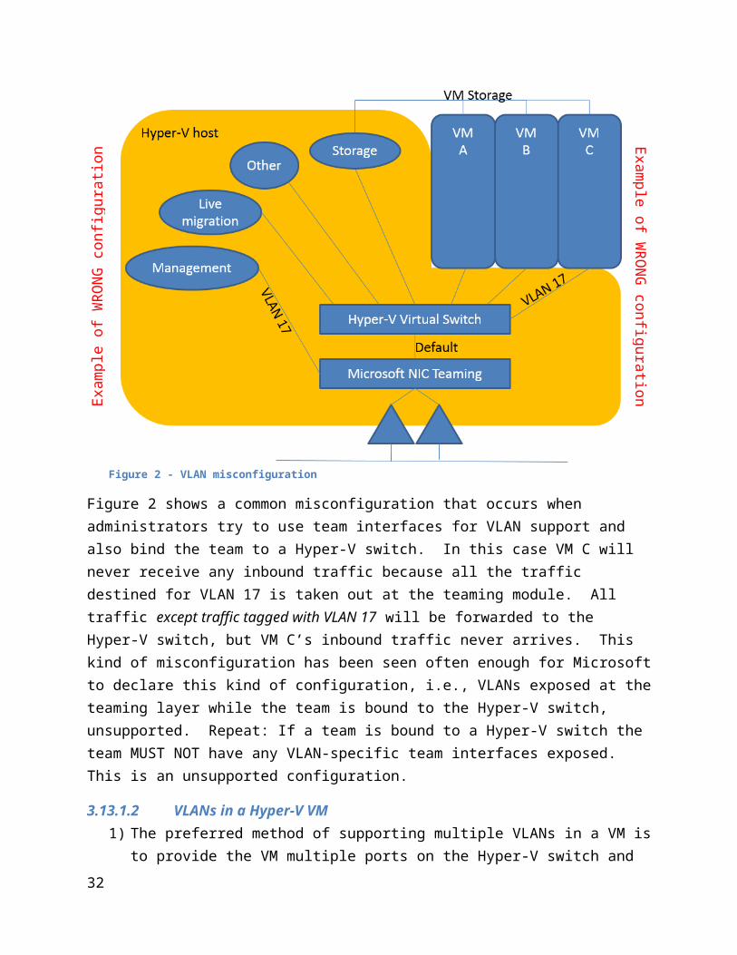
3.13.1.1VLANs in a Hyper-V hostIn a Hyper-V host VLANs should be configured only in the Hyper-V switch, not in the NIC Teaming software. Configuring team interfaces with VLANs can easily lead to VMs that are unable to communicate on the network due to collisions with VLANs assigned in the Hyper-V switch. Consider the following example:
7 Advanced users may choose to restrict the switch ports to only passing the VLANs present on the host. While this may slightly improve performance in networks with many VLANs that the local host doesn’t access, it risks creating difficult to diagnose problems when, for example, a VM is migrated to a host and it uses a VLAN not previously present on the destination host.
21
Exam
ple
of W
RON
G c
onfig
urati
onExam
ple of WRO
NG
configuration
Figure 4 - VLAN misconfiguration
Figure 4 shows a common misconfiguration that occurs when administrators try to use team interfaces for VLAN support and also bind the team to a Hyper-V switch. In this case VM C will never receive any inbound traffic because all the traffic destined for VLAN 17 is taken out at the teaming module. All traffic except traffic tagged with VLAN 17 will be forwarded to the Hyper-V switch, but VM C’s inbound traffic never arrives. This kind of misconfiguration has been seen often enough for Microsoft to declare this kind of configuration, i.e., VLANs exposed at the teaming layer while the team is bound to the Hyper-V switch, unsupported. Repeat: If a team is bound to a Hyper-V switch the team MUST NOT have any VLAN-specific team interfaces exposed. This is an unsupported configuration.
3.13.1.2VLANs in a Hyper-V VM1) The preferred method of supporting multiple VLANs in a VM is to provide the VM
multiple ports on the Hyper-V switch and associate each port with a VLAN. Never team these ports in the VM as it will certainly cause communication problems.
2) If the VM has multiple SR-IOV VFs make sure they are on the same VLAN before teaming them in the VM. It’s easily possible to configure the different VFs to be on different VLANs and, like in the previous case, it will certainly cause communication problems.
3) The only safe way to use VLANs with NIC Teaming in a guest is to team Hyper-V ports that are
22
a. Each connected to a different external Hyper-V switch, andb. Each configured to be associated with the same VLAN (or all associated with
untagged traffic only).c. TIP: If you must have more than one VLAN exposed into a guest OS consider
renaming the ports in the guest to indicate what the VLAN is. E.g., if the first port is associated with VLAN 12 and the second port is associated with VLAN 48, rename the interface Ethernet to be EthernetVLAN12 and the other to be EthernetVLAN48. Renaming interfaces is easy using the Windows PowerShell Rename-NetAdapter cmdlet or by going to the Network Connections panel in the guest and renaming the interfaces.
3.13.2 Interactions with other teaming solutionsSome users will want to use other NIC teaming solutions for a variety of reasons. This can be done but there are some risks that the system administrator should be aware of.
1. If the system administrator attempts to put a NIC into a 3rd party team that is presently part of a Microsoft NIC Teaming team, the system will become unstable and communications may be lost completely.
2. If the system administrator attempts to put a NIC into a Microsoft NIC Teaming team that is presently part of a 3rd party teaming solution team the system will become unstable and communications may be lost completely.
As a result it is STRONGLY RECOMMENDED that no system administrator ever run two teaming solutions at the same time on the same server. The teaming solutions are unaware of each other’s existence resulting in potentially serious problems.
In the event that an administrator violates these guidelines and gets into the situation described above the following steps may solve the problem.
1. Reboot the server. Forcibly power-off the server if necessary to get it to reboot.2. When the server has rebooted run this Windows PowerShell cmdlet:
Get-NetLbfoTeam | Remove-NetLbfoTeam
3. Use the 3rd party teaming solution’s administration tools and remove all instances of the 3rd party teams.
4. Reboot the server again.
Microsoft continues its longstanding policy of not supporting 3rd party teaming solutions. If a user chooses to run a 3rd party teaming solution and then encounters networking problems, the customer should call their teaming solution provider for support. If the issue is reproducible without the 3rd party teaming solution in place, please report the problem to Microsoft.
23
3.13.3 MAC address conflictsSee section 3.11.
3.13.4 Physical network segmentationNIC teaming is a layer 2 feature, meaning that all NICs in the team must be connected to the same subnet. In other words, there must always be a path to get from any NIC in the team to any other NIC in the team going only through layer 2 switches and not any layer 3 entities (e.g. routers). Administrators should check the physical layout and ensure that all NICs in the team are on the same subnet to avoid connectivity problems.
3.13.5 Hardware that doesn’t conform to specificationNIC teaming may send packets from the same IP address with multiple different source MAC addresses. Receivers of those packets must resolve the IP address of the host or VM to a single particular MAC instead of responding to the MAC address from which the packet was received. Clients that correctly implement the address resolution protocols, IPv4’s ARP or IPv6’s neighbor discovery protocol (NDP), will send packets with the correct destination MAC address (the MAC address of the VM or host that owns that IP address).
Microsoft has seen cases where certain embedded hardware, such as SAN controllers, do not correctly implement the address resolution protocols and/or do not explicitly resolve an IP address to a MAC address using ARP or NDP. Instead these non-conforming devices copy the source MAC contained in a received packet and use that as the destination MAC in the corresponding outgoing packets. This results in packets being sent to the wrong destination MAC address and thus getting dropped by the virtual switch because they don’t match any known destination.
Administrators that are having trouble connecting to SAN controllers or other embedded hardware should take packet captures and determine whether or not their hardware is implementing ARP or NDP and contact their hardware vendor for support.
3.13.6 Physical switch security featuresDepending on configuration, NIC teaming may send packets from the same IP address with multiple different source MAC address. This can trip up security features on the physical switch such as dynamic ARP inspection or IP source guard especially if the physical switch is not aware that the ports are part of a team (switch-independent mode). Administrators should check the switch logs to determine whether switch security features are causing connectivity problems with NIC teaming.
24
3.13.7 Disabling and Enabling with Windows PowerShellA common reason for a team to not be passing traffic is that the team interface is disabled. We’ve seen a number of cases where attempts to use the power of Windows PowerShell have resulted in unintended consequences. For example, the sequence:
Disable-NetAdapter *Enable-NetAdapter *
does not enable all the NetAdapters that it disabled. This is because disabling all the underlying physical member NICs will cause the team interface to be removed and no longer show up in Get-NetAdapter. Thus the Enable-NetAdapter * will not enable the team NIC since that adapter has been removed. It will however enable the member NICs, which will then (after a short time) cause the team interface to be recreated. The team interface will still be in a “disabled” state since it has not been re-enabled. Enabling the team interface after it is recreated will cause traffic to begin to flow again.
4 Managing NIC Teaming Windows Server 2012 R2 has two inbox management tools for managing NIC Teaming. Other Microsoft management products may also provide the ability to manage Windows Server 2012 R2 NIC teaming. Windows 8.1 client SKUs that allow the installation of the Remote Server Administration Tools (RSAT)8 are also able to manage NIC teaming on both Windows Server 2012 R2 hosts and Windows Server 2012 hosts.
This section provides a detailed presentation of the NIC Teaming management UI. For each operation the equivalent Windows PowerShell cmdlets will be provided. The NIC Teaming management UI operates exclusively through the use of Windows PowerShell underneath. Everything the UI does can be done with Windows PowerShell. The NIC Teaming Windows PowerShell module is NetLbfo and all the cmdlet names start with NetLbfo.
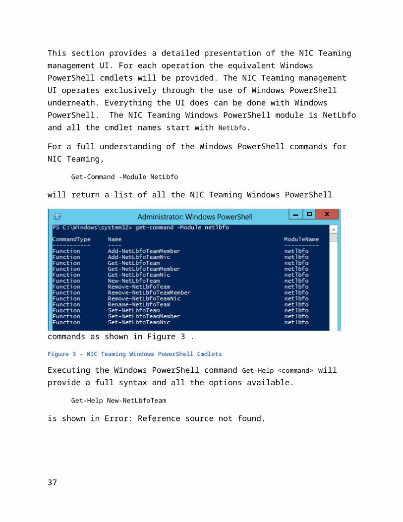
For a full understanding of the Windows PowerShell commands for NIC Teaming,
Get-Command -Module NetLbfo
will return a list of all the NIC Teaming Windows PowerShell commands as shown in Figure 5 .
8 RSAT tools for Windows 8.1 are available at http://microsoft.com
25
Figure 5 – NIC Teaming Windows PowerShell Cmdlets
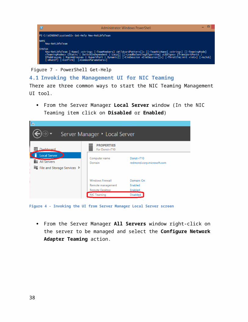
Executing the Windows PowerShell command Get-Help <command> will provide a full syntax and all the options available.
Get-Help New-NetLbfoTeam
is shown in Figure 6.
4.1 Invoking the Management UI for NIC TeamingThere are three common ways to start the NIC Teaming Management UI tool.
From the Server Manager Local Server window (In the NIC Teaming item click on Disabled or Enabled)
Figure 7 - Invoking the UI from Server Manager Local Server screen
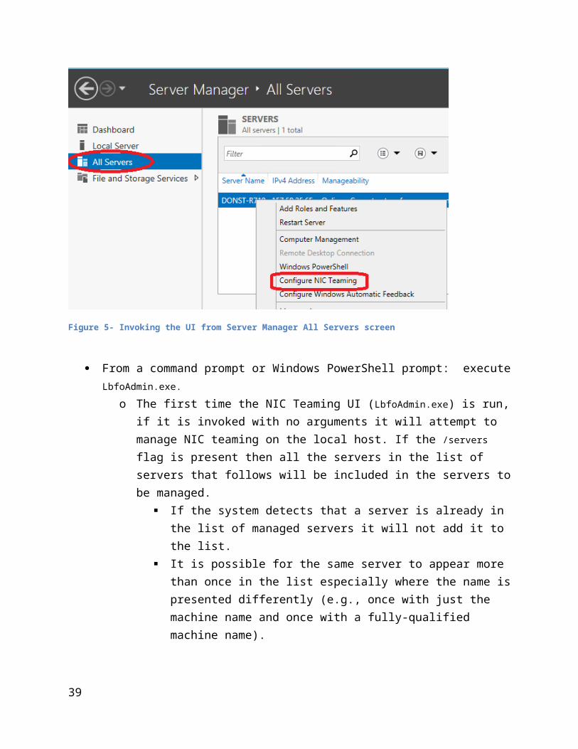
From the Server Manager All Servers window right-click on the server to be managed and select the Configure Network Adapter Teaming action.
26
Figure 6 - PowerShell Get-Help
Figure 8- Invoking the UI from Server Manager All Servers screen
From a command prompt or Windows PowerShell prompt: execute LbfoAdmin.exe. o The first time the NIC Teaming UI (LbfoAdmin.exe) is run, if it is invoked with no
arguments it will attempt to manage NIC teaming on the local host. If the /servers flag is present then all the servers in the list of servers that follows will be included in the servers to be managed.
If the system detects that a server is already in the list of managed servers it will not add it to the list.
It is possible for the same server to appear more than once in the list especially where the name is presented differently (e.g., once with just the machine name and once with a fully-qualified machine name).
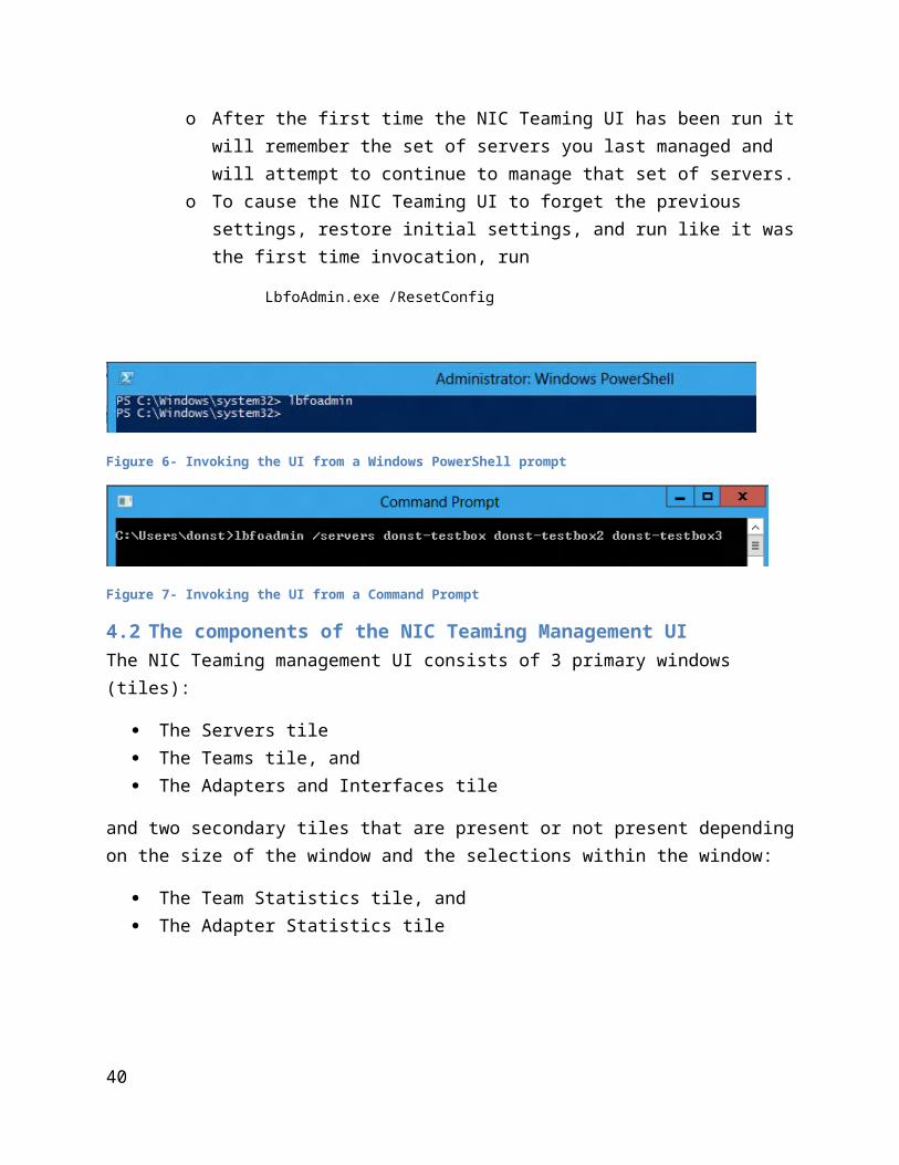
o After the first time the NIC Teaming UI has been run it will remember the set of servers you last managed and will attempt to continue to manage that set of servers.
o To cause the NIC Teaming UI to forget the previous settings, restore initial settings, and run like it was the first time invocation, run
LbfoAdmin.exe /ResetConfig
27
Figure 9- Invoking the UI from a Windows PowerShell prompt
Figure 10- Invoking the UI from a Command Prompt
4.2 The components of the NIC Teaming Management UIThe NIC Teaming management UI consists of 3 primary windows (tiles):
The Servers tile The Teams tile, and The Adapters and Interfaces tile
and two secondary tiles that are present or not present depending on the size of the window and the selections within the window:
The Team Statistics tile, and The Adapter Statistics tile
Figure 11 - the NIC Teaming Management UI tiles
28
The Adapters and Interfaces tile is shared by two tabs:
The Network Adapters tab The Team Interfaces tab
Each tile or tab has a set of columns that can be shown or hidden. The column chooser menus are made visible by right-clicking on any column header. (For illustrative purposes the screen shot in Figure 12 shows a column chooser in every tile and both the Network Adapters and Team Interfaces tabs active. Only one column chooser can be active at a time.)
Contents of any tile may be sorted by any column. To sort by a particular column left click on the column title. In Figure 12 the Servers tile is sorted by Server Name; the indication is the little triangle in the Name column title in the Servers tile.
Figure 12 - Column Chooser menus
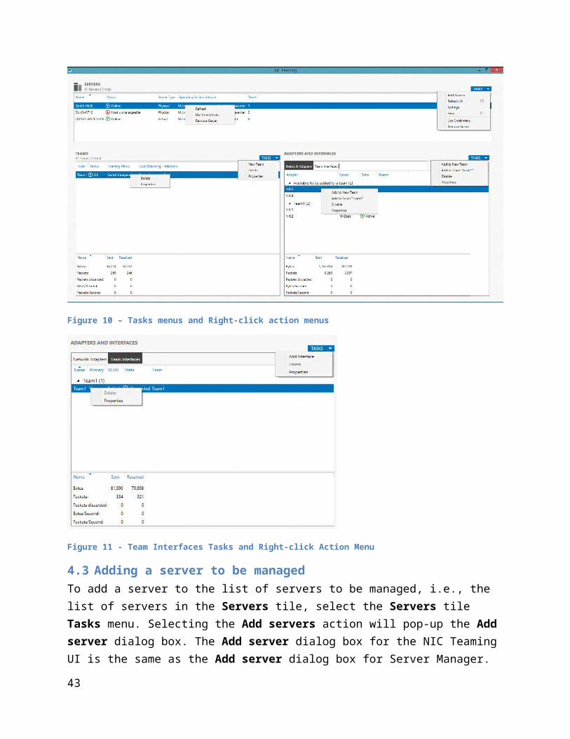
Each tile also has a Tasks dropdown menu and a right-click context menu. The Tasks menus can be opened by clicking on the Tasks box at the top right corner of the tile and then any available task in the list can be selected. The right-click context menus are activated by right-clicking in the tile. The menu options will vary based on context. (For illustrative purposes the screen shot in Figure 13 shows all the Tasks menus and a right-click menu in every tile. Only one right-click menu or Tasks menu can be active at any time.) Figure 14 shows the Tasks menus and right-click menu for the Team Interfaces tab.
29
Figure 13 – Tasks menus and Right-click action menus
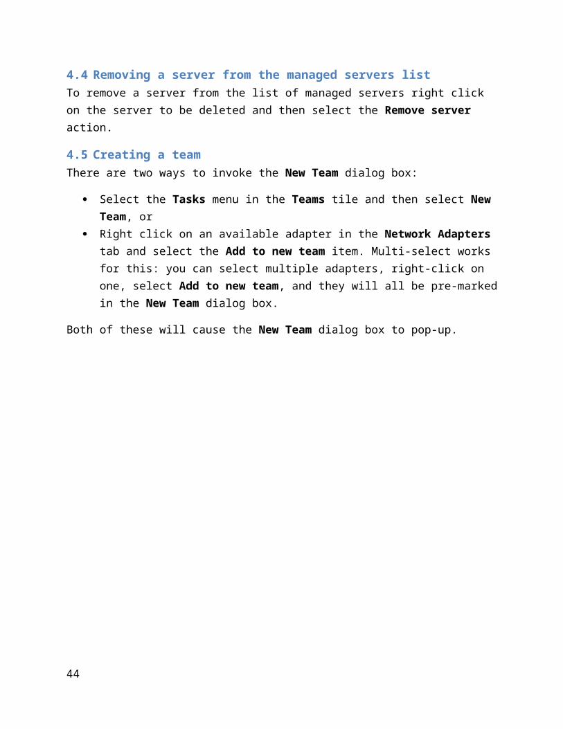
Figure 14 - Team Interfaces Tasks and Right-click Action Menu
4.3 Adding a server to be managedTo add a server to the list of servers to be managed, i.e., the list of servers in the Servers tile, select the Servers tile Tasks menu. Selecting the Add servers action will pop-up the Add server dialog box. The Add server dialog box for the NIC Teaming UI is the same as the Add server dialog box for Server Manager.
30
4.4 Removing a server from the managed servers listTo remove a server from the list of managed servers right click on the server to be deleted and then select the Remove server action.
4.5 Creating a teamThere are two ways to invoke the New Team dialog box:
Select the Tasks menu in the Teams tile and then select New Team, or Right click on an available adapter in the Network Adapters tab and select the Add to
new team item. Multi-select works for this: you can select multiple adapters, right-click on one, select Add to new team, and they will all be pre-marked in the New Team dialog box.
Both of these will cause the New Team dialog box to pop-up.
Figure 15 - New Team dialog box
31
When the New Team dialog box pops-up there are two actions that MUST be taken before the team can be created:
A Team name must be provided, and One or more adapters must be selected to be members of the team
Optionally, the administrator may select the Additional properties item and configure the teaming mode, load distribution mode, and the name of the first (primary) team interface.
Figure 16 - New Team dialog box with Additional Properties expanded
32
In Additional properties the Load distribution mode drop-down provides three options: Address Hash, Hyper-V Port, and Dynamic. The Address Hash option in the UI is the equivalent of the TransportPorts option in Windows PowerShell. To select additional Address hashing algorithms use Windows PowerShell as described below and in Section 4.7.2.3.
This is also the place where those who want to have a Standby adapter in the team (See Section 3.2) to set the Standby adapter. Selecting the Standby adapter drop-down will give a list of the team members. The administrator can set one of them to be the Standby Adapter. A Standby adapter is not used by the team unless and until another member of the team fails. Standby adapters are only permitted in Switch Independent mode. Changing the team to any Switch Dependent mode will cause all members to be made active members.
When the team name, the team members, and optionally any additional properties (including the Primary team interface name or standby adapter) have been set to the administrator’s choices, the administrator will click on the OK button and the team will be created. Team creation may take several seconds and the NICs that are becoming team members will lose communication for a very short time.
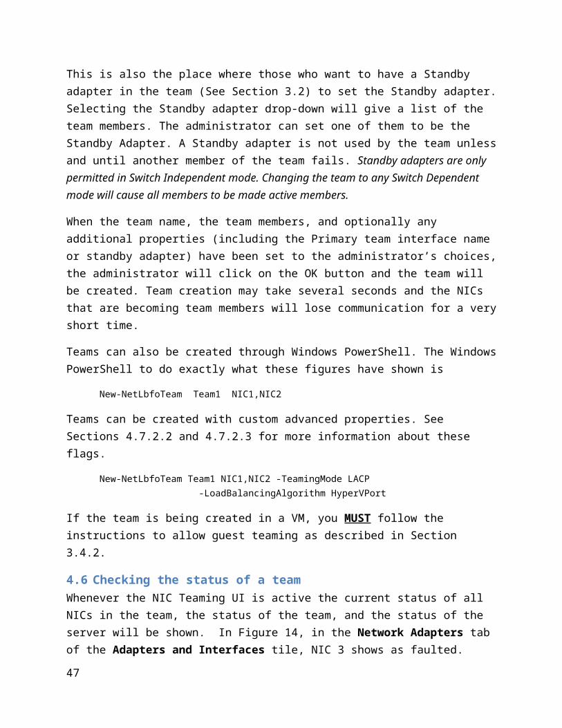
Teams can also be created through Windows PowerShell. The Windows PowerShell to do exactly what these figures have shown is
New-NetLbfoTeam Team1 NIC1,NIC2
Teams can be created with custom advanced properties. See Sections 4.7.2.2 and 4.7.2.3 for more information about these flags.
New-NetLbfoTeam Team1 NIC1,NIC2 -TeamingMode LACP-LoadBalancingAlgorithm HyperVPort
If the team is being created in a VM, you MUST follow the instructions to allow guest teaming as described in Section 3.4.2.
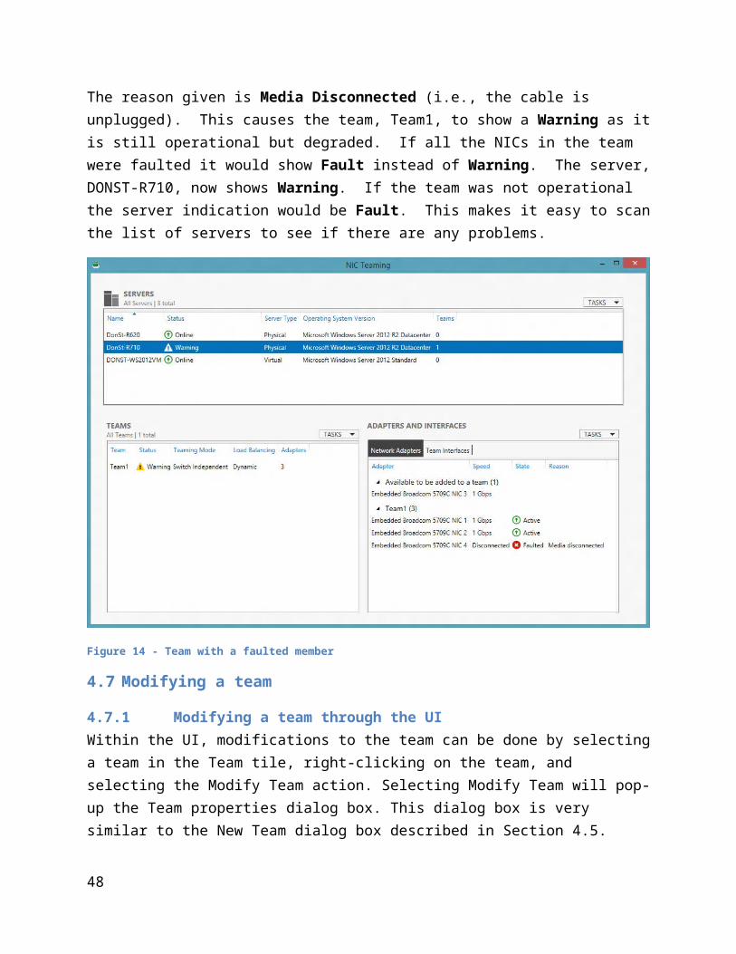
4.6 Checking the status of a teamWhenever the NIC Teaming UI is active the current status of all NICs in the team, the status of the team, and the status of the server will be shown. In Figure 17, in the Network Adapters tab of the Adapters and Interfaces tile, NIC 3 shows as faulted. The reason given is Media Disconnected (i.e., the cable is unplugged). This causes the team, Team1, to show a Warning as it is still operational but degraded. If all the NICs in the team were faulted it would show Fault instead of Warning. The server, DONST-R710, now shows Warning. If the team was not operational the server indication would be Fault. This makes it easy to scan the list of servers to see if there are any problems.
33
Figure 17 - Team with a faulted member
4.7 Modifying a team
4.7.1 Modifying a team through the UIWithin the UI, modifications to the team can be done by selecting a team in the Team tile, right-clicking on the team, and selecting the Modify Team action. Selecting Modify Team will pop-up the Team properties dialog box. This dialog box is very similar to the New Team dialog box described in Section 4.5.
In the Team properties dialog box the following actions can be accomplished:
Rename the team: Select the team name and edit it. Add team members: Select additional adapters from the Member Adapters tile Remove team members: De-select adapters from the Member Adapters tile. At least
one adapter must be selected.
34
Figure 18 - Modifying Team Properties
If the Additional properties drop-down item is selected then the Teaming mode and Load distribution mode may also be modified. This Additional properties drop-down also allows the administrator to select a standby adapter when active-standby mode is desired.
35
Figure 19 - Modifying a team's Teaming mode, Load distribution mode, and Standby Adapter
4.7.2 Modifying a team through Windows PowerShell
4.7.2.1 Renaming a teamTo rename Team1 and give it the name TeamA, the Windows PowerShell is:
Rename-NetLbfoTeam Team1 TeamA
4.7.2.2 Changing the teaming modeThe Windows PowerShell options for teaming mode are:
SwitchIndependent
36
Static LACP
These options are described further in Section 3.2.
To change Team1 to an 802.1ax LACP team, the Windows PowerShell is:
Set-NetLbfoTeam Team1 -TeamingMode LACP
The “-TeamingMode” flag can be abbreviated “-TM”, as in
Set-NetLbfoTeam Team1 –TM LACP
Note: For security reasons teams created in VMs may only operate in SwitchIndependent mode.
4.7.2.3 Changing the load distribution algorithmThe Windows PowerShell options for load distribution algorithm are:
TransportPorts IPAddresses MacAddresses HyperVPort Dynamic
The first three of these options represent the address hashing alternatives presented in Section 3.3.
TransportPorts, the default mode, is the same as what the UI calls Address Hash mode. In this mode the hash will be created using the TCP or UDP ports and the source and destination IP addresses as parameters to the hash creation algorithm. This creates the most granular traffic streams so it will normally result in the most even load distributions.
IPAddresses only uses the source and destination IP addresses as inputs to the hash creation function. As a result fewer streams will traffic will be identified. This will cause the streams to be larger and may result is a less well distributed traffic load than would be seen with TransportPorts. There is one situation where this mode is particularly useful: the traffic is either not TCP/UDP or the TCP/UDP headers are hidden. This would include, for example, a case where all traffic flowing across the team is IPsec traffic. Note, however, that the TransportPorts mode will fall back to this mode whenever the Transport Ports are not visible in the packets so there is really no need to set this mode.
37
MacAddresses seeds the hash creation algorithm with the source and destination MAC addresses. Functionally this is very similar in behavior to the IPAddresses option as there is usually a one-to-one correspondence between an IP address and a MAC address. This mode is really only useful if the traffic flowing across the team is not IP traffic. Note, however, that the IPAddresses mode will fall back to this mode whenever the IP addresses are not visible in the packets so there is really no need to set this mode.
The hash algorithm will always drop down to the level of the information available. For example, if the mode is set to TransportPorts but the traffic is all IPsec secured traffic, the teaming algorithm will automatically use IPAddresses mode for the IPsec traffic since the TCP/UDP ports are not visible to the team. NIC Teaming will continue to use the better modes for traffic that has the required information visible in the packets.
To change Team1’s Load balancing algorithm to Hyper-V Port, the Windows PowerShell is:
Set-NetLbfoTeam Team1 -LoadBalancingAlgorithm HyperVPort
The “-LoadBalancingAlgorithm” flag can be abbreviated “-LBA”, as in
Set-NetLbfoTeam Team1 -LBA HyperVPort
To change the Teaming mode and Load balancing algorithm at the same time,
Set-NetLbfoTeam Team1 -TM LACP -LBA HyperVPort
Note: Teams created in VMs may not use the HyperVPort load distribution algorithm.
4.7.2.4 Adding new members to the teamTo add NIC1 to Team1 the Windows PowerShell command is:
Add-NetLbfoTeamMember NIC1 Team1
4.7.2.5 Removing members from the teamTo remove NIC1 from Team1 the Windows PowerShell command is:
Remove-NetLbfoTeamMember NIC1 Team1
4.7.2.6 Setting a team member to be the Standby AdapterA team member can be set as the Standby Adapter through Windows PowerShell:
Set-NetLbfoTeamMember NIC4 -AdministrativeMode Standby
38
At most one team member may be in standby mode at any point in time. If a different team member is already in standby mode that team member must be returned to active mode before this Windows PowerShell cmdlet will succeed.
4.7.3 Adding new interfaces to the teamTo add a new interface to the team select the Team in the Teams Tile and the Team Interfaces tab in the Adapters and Interfaces tile. Select the Tasks menu in the Adapters and Interfaces tile, then select Add Interface.
Figure 20 - Selecting Add Interface
Selecting the Add Interface action item pops-up the New team interface dialog box.
Figure 21 - New team interface dialog box
39
Since only one team interface, the primary team interface, can be in Default mode, the new team interface must have a specific VLAN value. As the specific VLAN value is entered the name of the interface will be modified to be the team name followed by the VLAN value of this team interface. The interface name can be modified to any other name (duplicates are not allowed) if the administrator chooses to do so.
Selecting OK will create the new team interface.
Figure 22 - Team Interface tab after creating new team interface
The Windows PowerShell to add a team interface with VLAN 42 to Team1 is
Add-NetLbfoTeamNIC Team1 -VlanID 42
4.7.4 Modifying team interfaces There are only two modifications that can be done to a team interface:
change the team interface name and/or change the VLAN ID.
To modify the team interface VLAN ID select and then right-click the team interface in the Team Interfaces tab. Select the Properties action item.
40
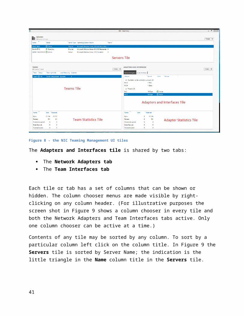
Figure 23 - Selecting a team interface to change the VLAN ID
This pops-up the Network Adapter Properties dialog box. This dialog box has some useful information about the team interface. It also has the box where the new VLAN ID can be entered. If a new VLAN ID is entered and the team name is the one the system provided when the team interface was created the team interface name will be changed to reflect the new VLAN ID. If the team interface name has been previously changed then the team name will not be changed when the new VLAN ID is entered.
41
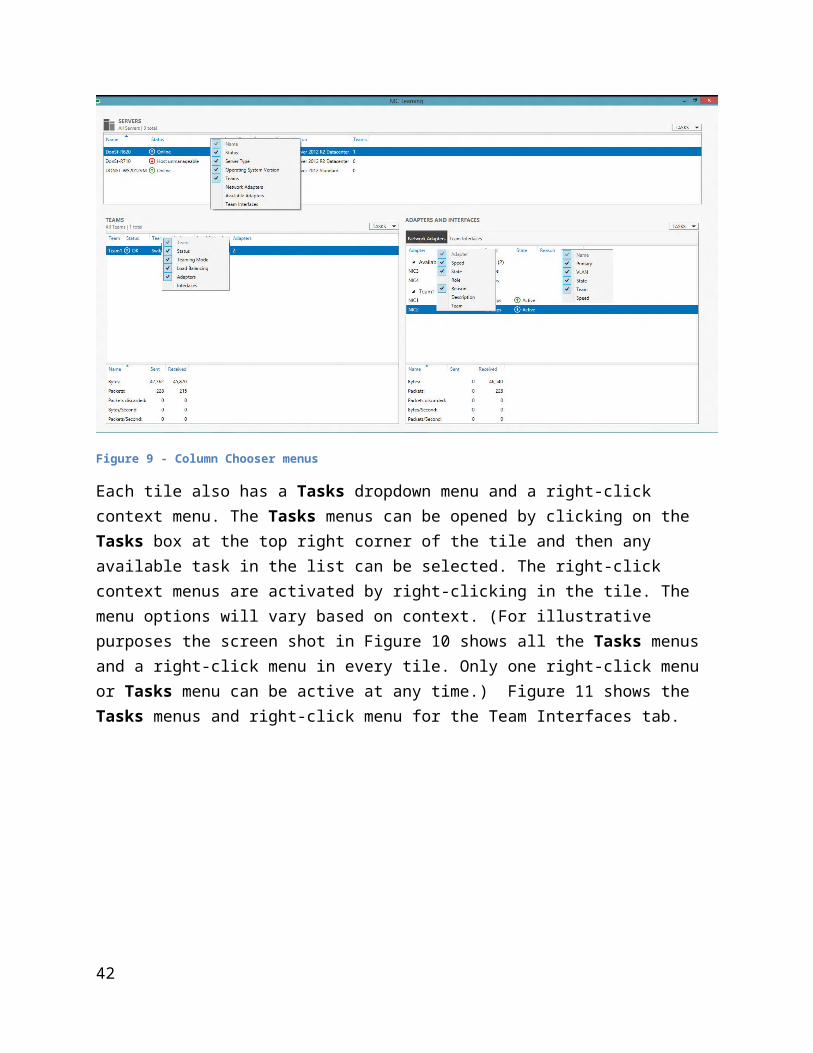
Figure 24- Network Adapter Properties dialog box for team interfaces
To modify a team interface’s VLAN ID in Windows PowerShell
Set-NetLbfoTeamNIC “Team1 - VLAN 42” -VlanID 15
Just as in the UI, changing the VLAN ID will cause the team interface name to change if the team interface name is still the same as the one the system created when the team interface was created. I.e., if the team interface name is <teamName - VLAN xx> where xx is the VLAN ID of the team interface, then the VLAN ID portion of the team interface name will be modified to reflect the new VLAN ID.
If the primary interface was assigned a VLAN and the administrator wants to set it to Default mode the Windows PowerShell command is:
42
Set-NetLbfoTeamNIC “Team1 - VLAN 12” -Default
Since only the primary team interface can be in Default mode this command will fail for any other team interface.
4.7.5 Removing interfaces from the teamTo delete a team interface, select and then right-click the team interface in the Team Interfaces tab. Select the Delete team interface action item. (See Figure 23.) A confirmation dialog box will pop-up. Once confirmed the team interface is deleted.
The Primary team interface (i.e., the one that was created when the team was created) can’t be deleted except by deleting the team.
To delete a team interface in Windows PowerShell
Remove-NetLbfoTeamNIC “Team1 - VLAN 42”
4.8 Deleting a teamTo delete a team from the server select the team in the Teams tile. Right-click the team and select the Delete team action item.
Figure 25 - Deleting a team
A confirmation dialog box will be displayed. Once confirmed the team will be deleted.
To delete a team in Windows PowerShell
Remove-NetLbfoTeam Team1
To remove all teams from the server in Windows PowerShell (i.e., to clean up the server),
Get-NetLbfoTeam | Remove-NetLbfoTeam
43
4.9 Viewing statistics for a team or team memberIf the UI window is sufficiently tall a statistics tile appears at the bottom of the Team tile and the Adapters and Interfaces tile. These statistics windows reflect the traffic of the selected team and selected team member. If you don’t see the statistics try making the UI window a little taller.
Figure 26- Statistics information for teams and team members
4.9.1 Viewing statistics for a team interfaceIf the Team Interfaces tab is selected in the Adapters and Interfaces tile the statistics at the bottom of the Adapters and Interfaces tile will be those of the selected team interface.
44
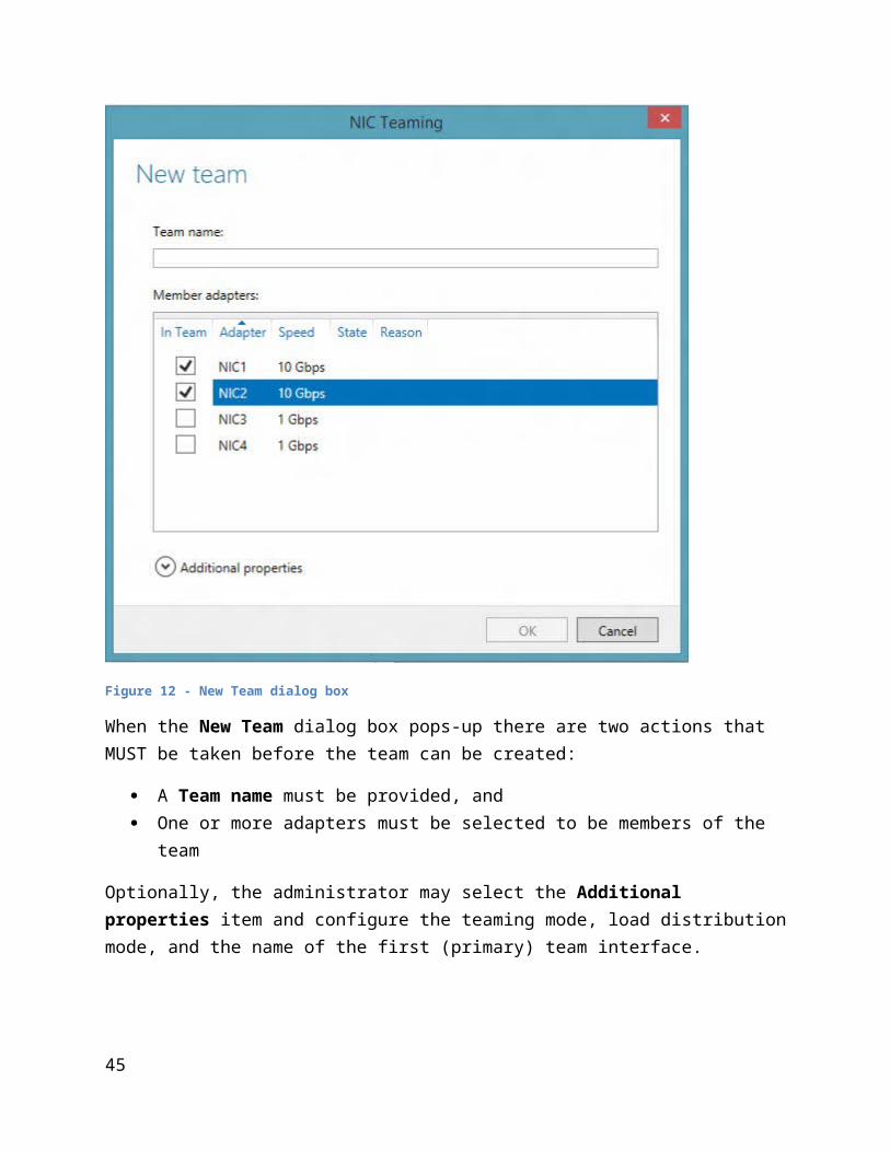
Figure 27- Statistics information for teams and team interfaces
4.9.2 Setting frequency of Statistics updatesThe frequency of statistics updates and other updates can be set by selection Settings in the Servers tile Tasks menu. Selecting this item brings up the General Settings dialog box.
45
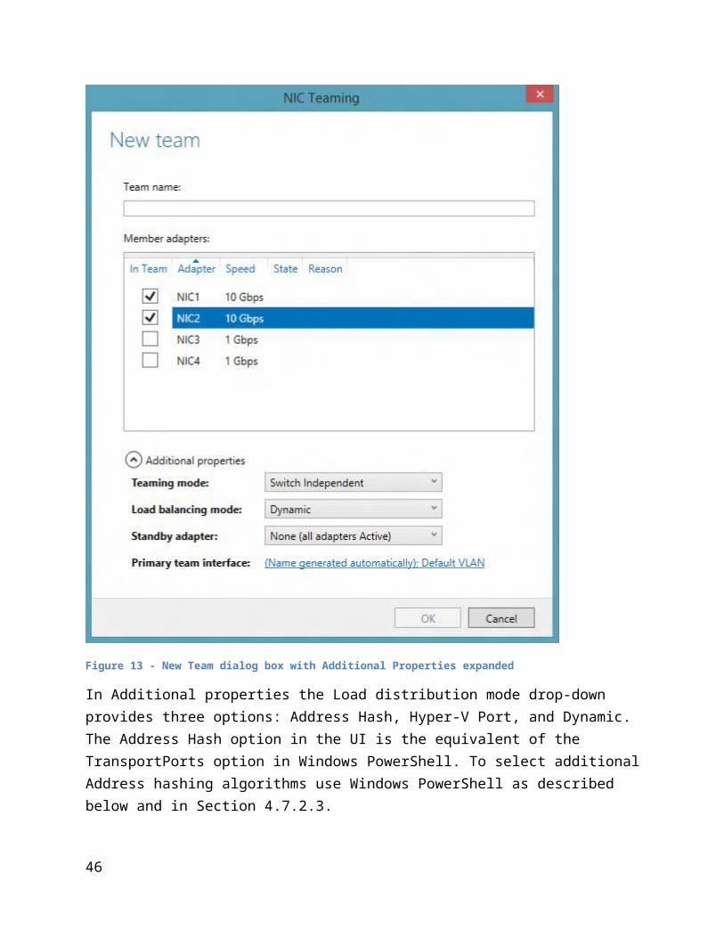
Figure 28 - General settings dialog box
The two drop-down lists in this dialog box allow the user to change how often the UI is refreshed. The settings apply equally to all servers in the servers list.
This menu also allows the administrator to decide whether or not adapters that are not able to be part of a team should be shown in the UI. By default these adapters that can’t be part of a team are not shown in the adapters list.
5 NIC Teaming differences between Windows Server 2012 R2 and Windows Server 2012
The primary user visible changes to NIC Teaming in the Windows Server 2012 R2 release include:
The addition of load balancing mode “Dynamic” for better performance and better balancing of NIC bandwidth utilization. See Section 3.3.
Improved performance and manageability with operating with Hyper-V Virtual Networking.
The addition of an Operating System Version column in the Servers tab of the NIC Teaming administration GUI tool so that the user can determine what level OS is being managed.
46
6 Frequently asked questions (FAQs)
Q1: Is Active/Standby (Active/Passive) mode supported?
Yes. Create a team with two members (Section 4.5). Set one as the Standby adapter (see advanced properties drop-down in Section 4.5). Teams with more than two members may be created, but only 1 member may be selected as the standby member. The standby member will be activated any time that one of the active members is faulted.
Q2: Do I have to select a standby member to get fault tolerance (failover)?
No. In any team with two or more network adapters if a network adapter fails in an Active/Active configuration, the traffic on that network adapter will gracefully failover to the other network adapters in the team even if none of the other adapters are in standby mode. Selecting a standby adapter does not improve failover latency or gracefulness.
Q3: What is the recommended configuration for Hyper-V?
See section 3.4.
Q4: Why does a NIC failure cause my VM to lose connectivity?
If the VM is running NIC teaming you MUST make sure you’ve followed the steps shown in Section 3.5.
Q5: How does KDNIC interact with NIC Teaming?
The kernel debug network adapter (KDNIC) should not be placed in a team (Rationale: this NIC isn’t meant for production use in servers).If you have an existing team built over a physical NIC and you enable network debugging over that NIC then the physical NIC is disabled (it shows up as “banged out” in device manager) and the KDNIC virtual adapter carries your network traffic instead. But the team is still attached over the physical NIC (which is now disabled), so the team will treat the NIC as failed. (The purpose of NIC teaming is to gracefully handle NIC failures so your teamed traffic will still flow uninterrupted through the other team members that have network connectivity).
If you need to use network debugging on a machine with NIC teaming you should set up debugging on a NIC that doesn’t participate in teaming.
47
Summary: network debugging does not coexist with NIC teaming. (This is by design.)
Q6: I can’t see the statistics for my team or for a NIC.
Just make the window a little taller. Statistics disappear if the UI window gets too short.
Q7: How can I tune my Hyper-V host for better CPU utilization by the NIC Teaming software?
See Section 3.7.1 to see how to select appropriate settings for VMQs.
Q8: Why does the NIC in my VM always show as disconnected when I put it in a team?
See Section 3.5. Only vmNICs connected to external switches are permitted to be teamed. vmNICs connected to internal or private switches will show as disconnected with error code SwitchLacksExternalConnectivity.
Q9: My firewall appliances or other core network infrastructure can’t seem to reach my VMs sometimes. Why not?
Standard practice requires equipment sending IP packets to do a lookup of the IP to MAC address mapping. Some equipment, however, in an effort to optimize their performance, may cache the source MAC address of the last packet in which a particular source IP address arrived. Since MAC address replacement is a common practice in NIC teaming solutions the cached MAC address may not be useable. This can lead to networking issues. We’ve seen this with one popular load balancer vendor in particular but it may occur with others as well.
Q10 I added a vSwitch on top of my team and now I can’t seem to get 10G worth of traffic to a single vNic. Why not?
RSS is not supported on Hyper-V virtual switch ports exposed to the host operating system and thus all the network processing for that vNic will happen on a single core. The amount of throughput a single core can handle will vary depending on hardware configuration, but 10G is generally much more than a single core can handle.
Q11 What is the difference between a team interface with VLAN 0 and the default team interface?
The team interface with VLAN 0 passes through only untagged traffic (i.e. traffic that has no VLAN), while the default interface passes through all traffic that is not claimed
48
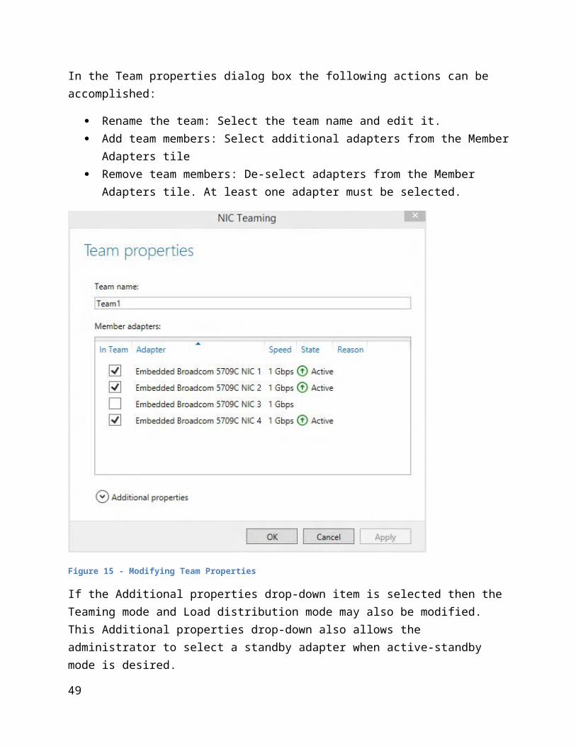
by any other interface.
49
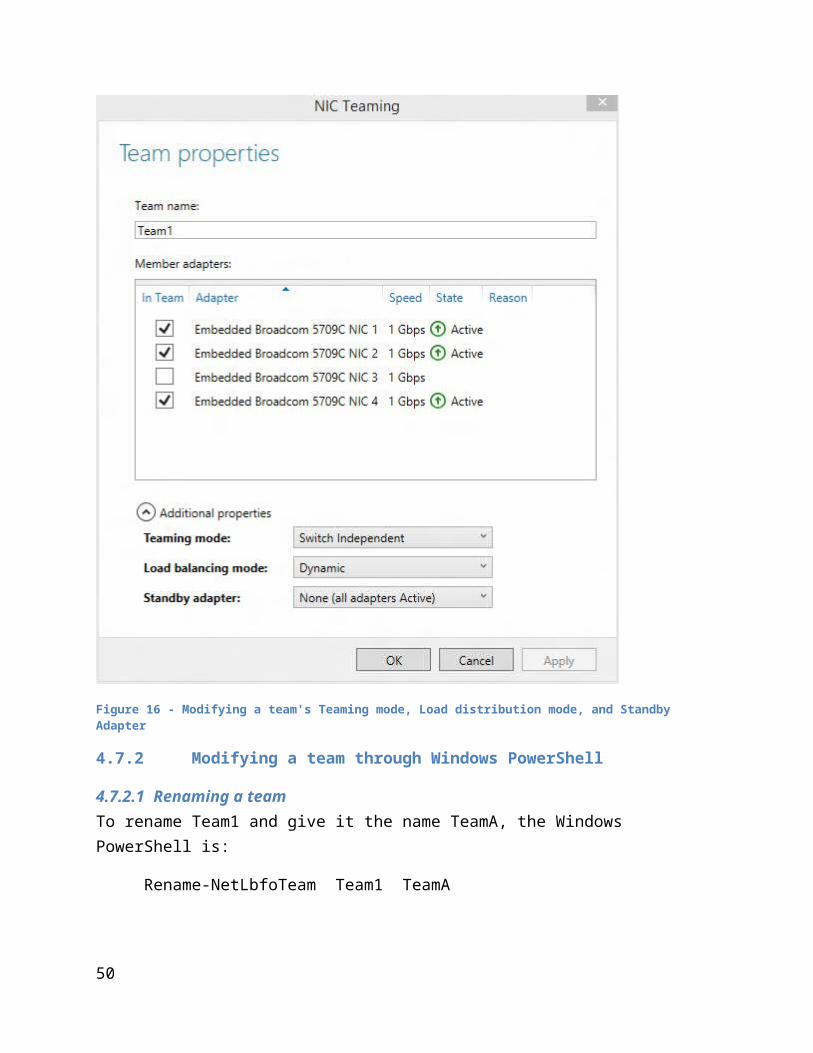
7 Power User tips for the NIC Teaming User InterfaceHere are some power-user tips for the NIC Teaming UI:
Quickly return to your most commonly-used servers. When you add a server to the NIC Teaming UI, you can quickly bring up that server again with the Windows taskbar’s Jump List. Right-click on the taskbar icon for NIC Teaming, and select the server name from the list. That’s it!
Customizing the UI. As mentioned in Section 4.2, columns may be added or removed from any tile. What that section didn’t mention is that tile contents may be sorted by any column. So, for example, the Servers tile could be sorted by the Server Type column so that the Physical Servers showed up above (or below) the Virtual Servers (VMs). Network adapters could be sorted by Speed or State, for example, if the administrator wanted that ordering instead of the default ordering.
Reset the GUI and start from scratch. The GUI will remember the servers you’ve added, the position of the main window, which columns you’ve hidden and shown, and any search filters you’ve saved. Most of the time, this is great. But if you ever want to start over with a clean slate, you can run
LbfoAdmin.exe /ResetConfig
to wipe away your old GUI settings, and load up the defaults. Of course, this will not affect the teams on any of your servers; it only resets GUI state.
Navigate the GUI from your keyboard. Keyboard lovers will appreciate these accelerators. You may have already guessed that F5 refreshes server status. But you can also hit ALT+1 to set focus to the Servers tile, ALT+2 to move to the Teams tile, ALT+3 to activate the Adapters tile, and ALT+4 to focus the Team Interfaces tile.
Authenticate to a non-domain-joined computer. If you would like to use different credentials to manage a remote server, you can right-click on the server name and select “Use Credentials…”. This feature is built on the same WinRM management technology as Windows PowerShell, and it can be configured in the same way. By default, non-domain-joined servers are not trusted for authentication. If you would like to allow a server to be trusted, you can use the Windows PowerShell command:
Set-Item WSMan:\localhost\Client\TrustedHosts myserver -Concatenate
This will allow you to authenticate against a server named “myserver”, whether you are using the Windows PowerShell Get-Credential cmdlet, or whether you are managing the server in the
50
NIC Teaming UI. Caution: this lowers the default security settings so you should only use this command in a trusted environment.
NIC Teaming speaks your language. If you manage servers in a multi-lingual environment, you might notice NetLbfo Windows PowerShell cmdlets or the NIC Teaming UI giving you messages in the wrong language. Some messages (most commonly, error messages) come from the target server, and are selected from the target server’s set of installed languages. You can install your favorite language pack on the target server to change the language of the server-generated messages.
51