wills rings
TRANSCRIPT

TRELLEBORG SEALING SOLUTIONS
YOUR PARTNER FOR SEALING TECHNOLOGY
WillsRings®
Your Partner for Sealing Technology
Trelleborg Sealing Solutions is a major international sealing
force, uniquely placed to offer dedicated design and
development from our market-leading product and material
portfolio: a one-stop-shop providing the best in elastomer,
thermoplastic, PTFE and composite technologies for applications
in aerospace, industrial and automotive industries.
With 50 years of experience, Trelleborg Sealing Solutions
engineers support customers with design, prototyping,
production, test and installation using state-of-the-art design
tools. An international network of over 70 facilities worldwide
includes over 20 manufacturing sites, strategically-positioned
research and development centers, including materials and
development laboratories and locations specializing in design
and applications.
Developing and formulating materials in-house, we utilize
the resource of our material database, including over 2,000
proprietary compounds and a range of unique products.
Trelleborg Sealing Solutions fulfills challenging service
requirements, supplying standard parts in volume or a single
custom-manufactured component, through our integrated
logistical support, which effectively delivers over 40,000 sealing
products to customers worldwide.
Facilities are certified to ISO 9001:2008 and ISO/TS 16949:2009.
Trelleborg Sealing Solutions is backed by the experiences and
resources of one of the world‘s foremost experts in polymer
technology: the Trelleborg Group.
The information in this brochure is intended to be for general reference purposes only and is not intended to be a specific recommendation for any individual application. The application limits for pressure, temperature, speed and media given are maximum values determined in laboratory conditions. In application, due to the interaction of operating parameters, maximum values may not be achieved. It is vital therefore, that customers satisfy themselves as to the suitability of product and material for each of their individual applications. Any reliance on information is therefore at the user‘s own risk. In no event will Trelleborg Sealing Solutions be liable for any loss, damage, claim or expense directly or indirectly arising or resulting from the use of any information provided in this brochure. While every effort is made to ensure the accuracy of information contained herewith, Trelleborg Sealing Solutions cannot warrant the accuracy or completeness of information.
To obtain the best recommendation for a specific application, please contact your local Trelleborg Sealing Solutions marketing company.
This edition supersedes all previous brochures. This brochure or any part of it may not be reproduced without permission.
® All trademarks are the property of Trelleborg Group.
The turquoise color is a registered trademark of Trelleborg Group.
© 201 , Trelleborg Group. All rights reserved.
ISO 9001:2008 ISO/TS 16949:2009
tss_cat-p2-873_gb.indd 1 08.03.11 10:24
2

1Latest information available at www.tss.trelleborg.comEdition November 2012
Wills Rings®
Contents Introduction .................................................................................................................................................................................. 3
Method of Operation ................................................................................................................................................................... 4
Selection Table .............................................................................................................................................................................. 5
Materials .................................................................................................................................................................................. 6
Hardware, Finish and Media ........................................................................................................................................................ 8
Wills Rings® O ................................................................................................................................................................................. 9
Wills Rings® C ............................................................................................................................................................................... 11
Wills Rings® O and C / Special Designs For Non-Circular Grooves ............................................................................................. 12
Compression Loads to Seat Wills Rings® ..................................................................................................................................... 13
Calculating Seating Loads ........................................................................................................................................................... 14
Groove Designs ............................................................................................................................................................................. 16
Part Numbers and Ordering Instructions in Metric ................................................................................................................... 18
Installation Recommendations for Internal Pressure Sealing ........................................................................................ 18
Installation Recommendations for External Pressure Sealing ........................................................................................ 21
Metric Part Numbers and Ordering Instructions ........................................................................................................................ 24
Metric Size Ranges and Free Heights .............................................................................................................................. 24
Metric Groove Clearance and Plating Allowances .......................................................................................................... 25
Metric Part Number Systems for Wills Rings® ................................................................................................................. 26
Inch Part Numbers and Ordering Instructions ............................................................................................................................ 28
Inch Size Ranges and Free Heights .................................................................................................................................. 28
Inch Groove Clearance and Plating Allowances ............................................................................................................. 29
Inch Part Number Systems for Wills Rings® ..................................................................................................................... 30
Quality Criteria ............................................................................................................................................................................ 32
Storage ......................................................................................................................................................................................... 32
Conversion Tables ........................................................................................................................................................................ 34
Technical Questionnaire .............................................................................................................................................................. 35
Digital Services ............................................................................................................................................................................. 36

2 Latest information available at www.tss.trelleborg.comEdition November 2012
Wills Rings®

3Latest information available at www.tss.trelleborg.comEdition November 2012
Wills Rings®
Trelleborg Sealing Solutions designs and manufactures a wide range of seals and bearings, which are used in many industries and applications, including Wills Rings®. Wills Rings® are the original metal O-Ring seals. First developed at the Trelleborg Sealing Solutions facility in Bridgwater, the term Wills Rings® has become synonymous with this type of seal and is internationally used as a generic term to describe metal O-Ring seals.
Superior controlled compression type seals used in static applications, Wills Rings® withstand extreme conditions that exceed the capabilities of elastomer and polymer seals. The seals are constructed from high quality metal tubing or strip in standard or thin wall thickness and are often coated or plated with a softer material to increase their sealing performance.
Wills Rings® are available in two designs and five types, see Figure 1. The designs are:
1) Wills Rings® O
2) Wills Rings® C
Wills Rings® O consist of a tube formed into a circular profile.
Wills Rings® C are similar to Wills Rings® O but with an open ‘C’ cross section. The open slot of the Wills Rings® C faces toward the system pressure and allows the seal to be pressure activated.
Typical applications for Wills Rings®:
- Nuclear power plants
- Furnaces
- Offshore and marine installations
- Cryogenic situations
- Ultra-high vacuum systems
- Fire safe valves
- Plastic processing plants
- High-performance vehicles
Wills Rings® can be customized to suit the specific requirements of a system. Contact your local Trelleborg Sealing Solutions marketing company for more information.
� IntroductionType MOT
Type MOU
Type MOS
Type MOV
P
Type MCX
P
Figure 1 Wills Rings® variations

4 Latest information available at www.tss.trelleborg.comEdition November 2012
Wills Rings®
� Method of Operation
Wills Rings® consist of a metal ring, often coated, which is used as a deformable seal in a static sealing situation. The ring is located between two flanges and undergoes a controlled compression.
Wills Rings® are defined by their free height, which is the cross section in the axial direction of the seal (Figure 2). The free height d2 of the seal is compressed down to the groove depth h.
The resistance of the ring to compression enables it to generate a sealing force when compressed. The resilient effect of the seal can be increased by pressurizing the internal volume of the ring, see Type MOT gas filled Wills Rings® O.
Alternatively, if the system to be sealed is very high pressure, this system pressure can be used to provide additional sealing effect. This is called system actuation and is achieved by allowing the high pressure to enter the seal through vent holes, see Type MOV or the open C slot, Type MCX.
Wills Rings® have a certain degree of elasticity. This is known as springback. The springback is the elastic part of the seal deflection when it is installed in a groove. This dictates the seal’s ability to absorb or compensate for hardware variations due to temperature or pressure loadings, maintaining the seal integrity (Figure 2).
A softer plating or coating material can be applied to Wills Rings® to maximize sealing performance in demanding applications. The coating material yields during the ring compression and fills surface machining marks (Figure 3).
For best sealing results Wills Rings® should be replaced each time the groove housing is dismantled as the plating or coating material deforms from use and performance can´t be guaranteed again once the housing has been dismantled.
Performance
Because Wills Rings® are constructed from metal, their ability to handle extreme conditions exceeds that of polymeric and elastomeric seal types.
Unlike elastomer seals, Wills Rings® are not subject to outgassing making them suitable for use on equipment sensitive to outgassing.
Features and benefits
- Temperature range from cryogenic to 850 °C / 1,550 °F
- Pressure range from ultra-high vacuum to 1,000 MPa / 145,000 psi
- Compatible with a large range of media
- Corrosion resistant and radiation tolerant
- Simple and reliable sealing
- No outgassing
- Immune to explosive decompression
- Wide range of sizes
Before Installation
Installed
After Installation
Gro
ove
Dep
th h
Spri
ng
bac
k
Free
Hei
gh
t d
2
Wal
l Th
ickn
ess
Figure 2 Method of seal operation
Non-Coated Seal
Coated Seal
Figure 3 Contact surface for coated and non-coated Wills Rings®

5Latest information available at www.tss.trelleborg.comEdition November 2012
Wills Rings®
� Selection Table
Use this table to select the optimum seal for an application. A, B, C or D indicates relative performance.
Further information can be found on the relevant pages as indicated.
Table 1 Selection Criteria
If further information on seal selection is required please contact your local Trelleborg Sealing Solutions Marketing Company. Inconel® is a trademark of INCO Alloys International, Inc.
Seal Extreme Con-
ditions
Seating Loads
Spring-back
Vacuum Sealing
Pressure
MPa/psi
Max. Working
Temp. °C / °F
Standard Material
Code PageCyrogenic
toSeal Coating
Type MOT
9Pres-
surizedA C C 1x10⁻⁹ mbar.l.s.-1
40 MPa 5,800 psi
850 °C
1,550 °F
Mild steel
Stainless Steel 316 L
Stainless Steel 321
Inconel® 600
Inconel® 718
Copper
Silver
Nickel
Copper
Gold
Indium
Type MOV
9Vented internal
B B C -1,000 MPa 145,000 psi
600 °C 1,100 °F Type MOW
9Vented external
Type MOU
10Non- Pres-
surizedC B C 1x10⁻⁵ mbar.l.s.-1
4 MPa 580 psi
400 °C 750 °F
Type MOS
10 Solid C D D 1x10⁻⁵ mbar.l.s.-1 4 MPa 580 psi
500 °C 925 °F
Type MCX
12Internal pressure
B A A 1x10⁻⁷ mbar.l.s.-1 200 MPa
29,000 psi750 °C
1,375 °F
Inconel® X750
Inconel® 718
Silver
Nickel
Copper
Gold
Indium
Type MCY
12External pressure
Properties: A = Excellent B = Good C = Satisfactory D = Poor
6 Latest information available at www.tss.trelleborg.comEdition November 2012
Wills Rings®
� Materials
Seal Material
Available in a wide range of materials, Wills Rings® are used as static seals in a large number of industrial sectors. The choice of material affects the seal performance and materials should be chosen after considering the following requirements:
- Pressure and temperature
- Seating loads
- Corrosion resistance
- Compatibility with housing materials
- Length of life
- Sealing level
- Cost
Industry Standards
For some industries seal material selection can be critical and require compliance with industry standards.
For example, a Wills Rings® O or C with compliance to NACE MR0175 should be selected in material Inconel® 718 and be hardened using treatment 5 as shown in the part number tables.
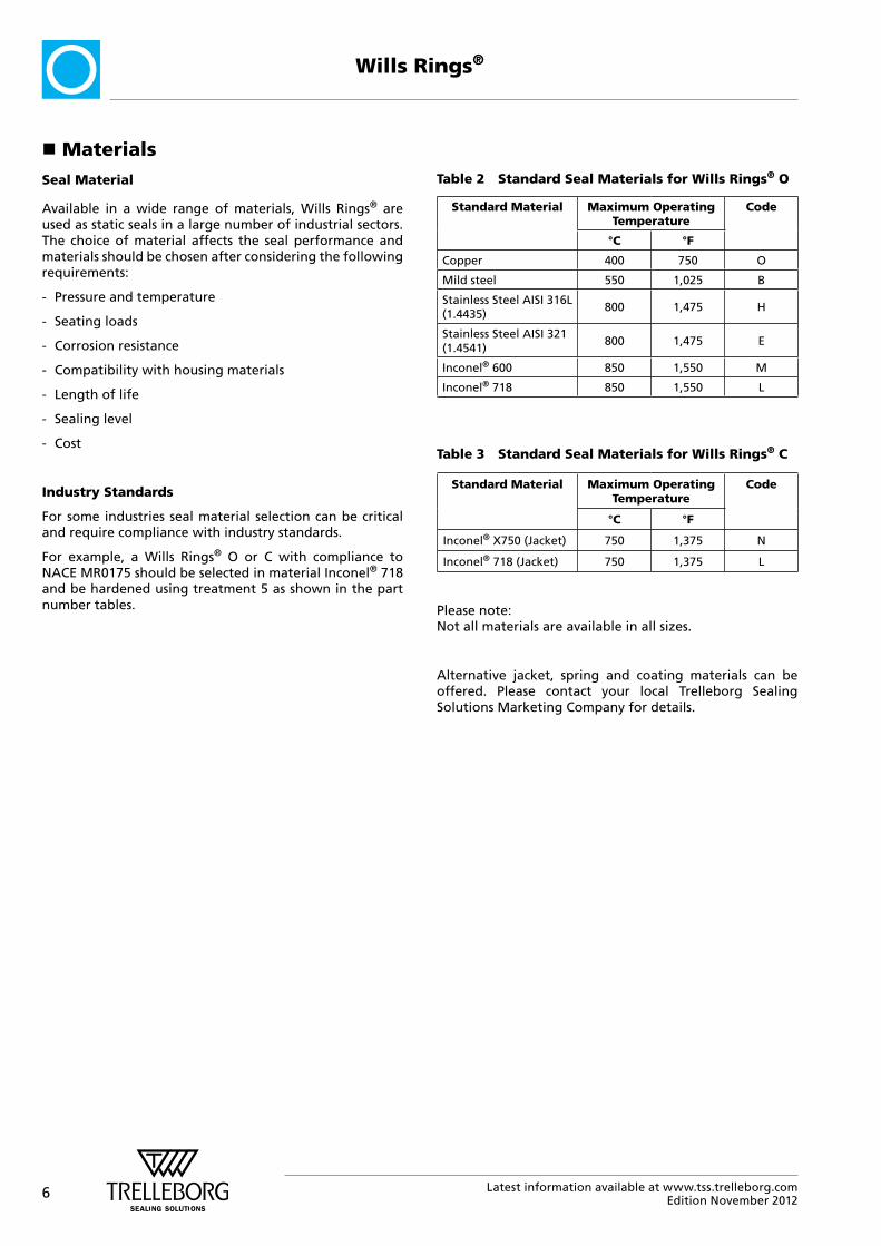
Table 2 Standard Seal Materials for Wills Rings® O
Standard Material Maximum Operating Temperature
Code
°C °F
Copper 400 750 O
Mild steel 550 1,025 B
Stainless Steel AISI 316L (1.4435)
800 1,475 H
Stainless Steel AISI 321 (1.4541)
800 1,475 E
Inconel® 600 850 1,550 M
Inconel® 718 850 1,550 L
Table 3 Standard Seal Materials for Wills Rings® C
Standard Material Maximum Operating Temperature
Code
°C °F
Inconel® X750 (Jacket) 750 1,375 N
Inconel® 718 (Jacket) 750 1,375 L
Please note: Not all materials are available in all sizes.
Alternative jacket, spring and coating materials can be offered. Please contact your local Trelleborg Sealing Solutions Marketing Company for details.
7Latest information available at www.tss.trelleborg.comEdition November 2012
Wills Rings®
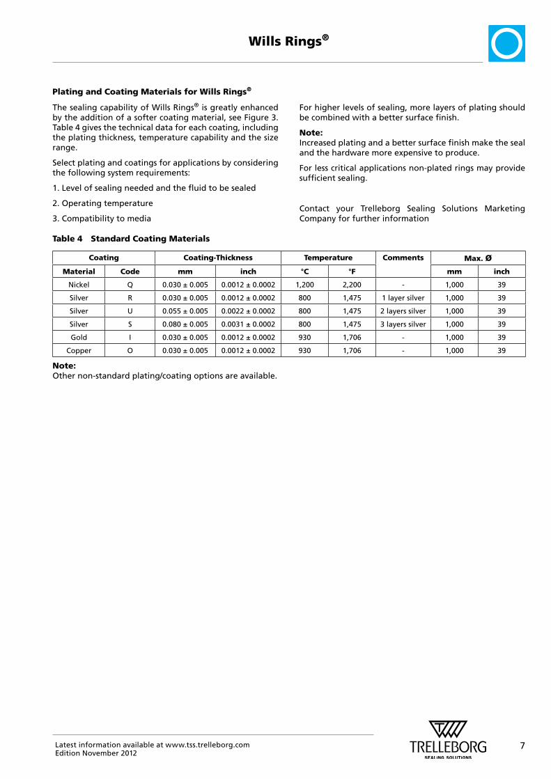
The sealing capability of Wills Rings® is greatly enhanced by the addition of a softer coating material, see Figure 3. Table 4 gives the technical data for each coating, including the plating thickness, temperature capability and the size range.
Select plating and coatings for applications by considering the following system requirements:
1. Level of sealing needed and the fluid to be sealed
2. Operating temperature
3. Compatibility to media
For higher levels of sealing, more layers of plating should be combined with a better surface finish.
Note:Increased plating and a better surface finish make the seal and the hardware more expensive to produce.
For less critical applications non-plated rings may provide sufficient sealing.
Contact your Trelleborg Sealing Solutions Marketing Company for further information
Table 4 Standard Coating Materials
Coating Coating-Thickness Temperature Comments Max. Ø
Material Code mm inch °C °F mm inch
Nickel Q 0.030 ± 0.005 0.0012 ± 0.0002 1,200 2,200 - 1,000 39
Silver R 0.030 ± 0.005 0.0012 ± 0.0002 800 1,475 1 layer silver 1,000 39
Silver U 0.055 ± 0.005 0.0022 ± 0.0002 800 1,475 2 layers silver 1,000 39
Silver S 0.080 ± 0.005 0.0031 ± 0.0002 800 1,475 3 layers silver 1,000 39
Gold I 0.030 ± 0.005 0.0012 ± 0.0002 930 1,706 - 1,000 39
Copper O 0.030 ± 0.005 0.0012 ± 0.0002 930 1,706 - 1,000 39
Note: Other non-standard plating/coating options are available.
Plating and Coating Materials for Wills Rings®

8 Latest information available at www.tss.trelleborg.comEdition November 2012
Wills Rings®
Table 5 shows the media that can be sealed with different plating materials and the required surface finish for the housing. It is important that all machining marks are concentric with the line of seal contact. Spiral or radial marks should be avoided as these can form leak paths across the seal face.
The groove should be machined to the required finish and not polished by hand. Polishing can lead to radial marks on the sealing surface which may form leak paths.
Typically a thin gas is more difficult to seal than a heavy liquid, and requires a better surface finish. The lower the media viscosity, the higher the surface finish quality and plating level required.
Table 5 Media and Hardware Surface Finishes
Sealing System/Media Ra Rmax Typical
Coating
Comments
m inch m inch
Ultra-high vacuum 0.1 - 0.2 4 - 8 1.2 - 1.6 48 - 64 SUse this for safety
critical systemsCryogenic - High vacuum 0.1 - 0.2 4 - 8 1.2 - 1.6 48 - 64 S
Helium, Hydrogen 0.1 - 0.2 4 - 8 1.2 - 1.6 48 - 64 S
Nitrogen, Steam 0.2 - 0.4 8 - 16 2.0 - 2.5 80 - 100 R/S/Q -
Cryogenic - Light vacuum 0.2 - 0.4 8 - 16 2.0 - 2.5 80 - 100 R/S/Q -
Air, Water, Light fuel 0.4 - 0.8 16 - 32 3.0 - 4.0 120 - 160 R/Q Non-plated rings may be suitableHeavy oils, Polymer 0.4 - 0.8 16 - 32 3.0 - 4.0 120 - 160 R/Q
� Hardware, Finish and Media

9Latest information available at www.tss.trelleborg.comEdition November 2012
Wills Rings®
� Wills Rings® O Type MOT (Gas Filled)
The most frequently used Wills Rings® are filled with nitrogen gas. The gas pressure inside the seal rises with temperature to offset the loss of tubing strength at elevated temperatures.
Advantages
- High temperature capability
- Available in a wide range of materials and finishes
- Resistant to corrosion, chemical attack and radiation
- Long Life
- Resilient (springback)
Technical Data
Operating Pressure: Vacuum - helium tight 1 x 10⁻⁹ mbar.l.s-1 up to 40 MPa / 5,800 psi
Temperature: Cryogenic to 850 °C / 1,550 °F (constant temperature)
Seal Type: Internal and external sealing pressure
Standard Materials: Stainless Steel
Coating Materials: Gold Indium Copper Nickel Silver
Note: Other non-standard plating/coating options are available.
d2Øda
Figure 4 Wills Rings® O - Type MOT
� Wills Rings® O Type MOV Internal Pressure Type MOW External Pressure (System Pressure Actuated)
These seals are ideal for extreme pressure applications. System pressure actuates the seal ring through vent holes on the seal wall. The vent holes are on the inside diameter for internal pressure (Type MOV), and on the outside diameter for external pressure (Type MOW).
These vent holes enable the internal pressure of the seal to equal the system pressure.
Advantages
- High pressure capability
- Available in a wide range of materials and finishes
- Resistant to corrosion, chemical attack and radiation
- Long life
Technical Data
Operating Pressure: 7 to 1,000 MPa / 1,015 to 145,000 psi
Temperature: Cryogenic to 600 °C / 1,100 °F (constant temperature)
Seal Type: Internal and external pressure sealing
Standard Materials: Stainless Steel
Coating Materials: Gold Indium Copper Nickel Silver Note:
Other non-standard plating/coating options are available.
Type MOVInternal Pressure
Type MOWExternal Pressure
d2Øda
Figure 5 Wills Rings® O - Type MOV internal vented / MOW external vented

10 Latest information available at www.tss.trelleborg.comEdition November 2012
Wills Rings®
� Wills Rings® O Type MOU Non-Pressurized
As these types of Wills Rings® O are filled at atmospheric pressure only, they are suitable for moderate sealing. This limits the safe maximum working temperature.
Advantages
- Available in a wide range of materials and finishes
- Resistant to corrosion, chemical attack and radiation
- Long life
- Cost-effective in less demanding applications
Technical Data
Operating Pressure: Vacuum - bubble tight 1 x 10⁻⁵ mbar.l.s-1 Pressure - up to 4 MPa / 580 psi
Temperature: Cryogenic to 400 °C / 750 °F
Seal Type: Internal and external pressure sealing
Standard Materials: Stainless Steel
Coating Materials: Gold Indium Copper Nickel Silver
Note: Other non-standard plating/coating options are available.
d2Øda
Figure 6 Wills Rings® O - Type MOU
� Wills Rings® O Type MOS Solid
Solid seals exhibit virtually no elastic behavior and also have very high seating loads. Being crush seals, solid Wills Rings® O operate in a similar manner to gaskets.
Advantages
- Good vacuum sealing capability
- Available in a wide range of materials and finishes
- Resistant to corrosion, chemical attack and radiation
- Long life
- Cost-effective in less demanding applications
Technical Data
Operating Pressure: Vacuum - bubble tight 1 x 10⁻⁵ mbar.l.s-1 Pressure - up to 4 MPa / 580 psi
Temperature: Cryogenic to 500 °C / 925 °F
Seal Type: Internal and external pressure sealing
Standard Materials: Stainless Steel
Coating Materials: Gold Indium Copper Nickel Silver
Note: Other non-standard plating/coating options are available.
Øda d2
Figure 7 Wills Rings® O - Type MOS
11Latest information available at www.tss.trelleborg.comEdition November 2012
Wills Rings®
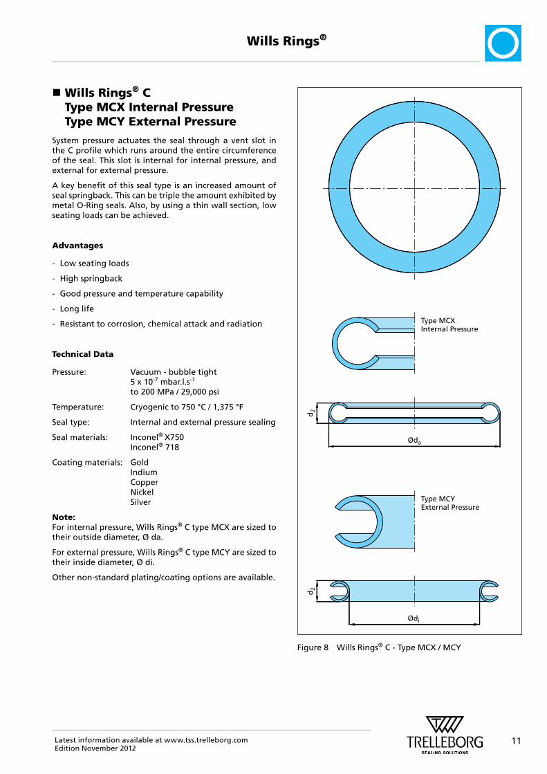
� Wills Rings® C Type MCX Internal Pressure Type MCY External Pressure
System pressure actuates the seal through a vent slot in the C profile which runs around the entire circumference of the seal. This slot is internal for internal pressure, and external for external pressure.
A key benefit of this seal type is an increased amount of seal springback. This can be triple the amount exhibited by metal O-Ring seals. Also, by using a thin wall section, low seating loads can be achieved.
Advantages
- Low seating loads
- High springback
- Good pressure and temperature capability
- Long life
- Resistant to corrosion, chemical attack and radiation
Technical Data
Pressure: Vacuum - bubble tight 5 x 10⁻⁷ mbar.l.s-1 to 200 MPa / 29,000 psi
Temperature: Cryogenic to 750 °C / 1,375 °F
Seal type: Internal and external pressure sealing
Seal materials: Inconel® X750 Inconel® 718
Coating materials: Gold Indium Copper Nickel Silver
Note:For internal pressure, Wills Rings® C type MCX are sized to their outside diameter, Ø da.
For external pressure, Wills Rings® C type MCY are sized to their inside diameter, Ø di.
Other non-standard plating/coating options are available.
Type MCXInternal Pressure
Type MCYExternal Pressure
d2
Øda
d2
Ødi
Figure 8 Wills Rings® C - Type MCX / MCY

12 Latest information available at www.tss.trelleborg.comEdition November 2012
Wills Rings®
� Wills Rings® O and C Special Designs For Non-Circular Grooves
Wills Rings® can be supplied in a variety of specially manufactured shapes to accommodate non-circular flanges and vessels. When designing this type of seal the minimum bending radius in relation to the free height must be observed, see Table 6, as opposed to the minimum seal diameter for a given seal free height.
For further information on special seal designs please contact your local Trelleborg Sealing Solutions Marketing Company.
Table 6 Minimum Bending Radius
Free Height d2 Minimum Bending Radius
mm inch mm inch
1.59 0.063 7 0.276
2.38 0.094 13 0.500
3.18 0.125 30 1.181
3.97 0.156 50 2.000
4.76 0.187 75 3.000
6.35 0.250 100 4.000
7.94 * 0.313 200 8.000
9.53 * 0.375 300 12.000
* Not available in Wills Rings® C
Figure 9 Example of a non-circular seal
13Latest information available at www.tss.trelleborg.comEdition November 2012
Wills Rings®
� Compression Loads to Seat Wills Rings®
Seating the seal is the process of compressing it to the correct depth, such that it forms an effective seal.
When Wills Rings® are located in a housing, a specific load must be applied to the flanges to seat the seals correctly.
The required seating load must be calculated for each seal and must be exceeded by the system load used to secure the sealing flanges together. The system pressure for internal pressure systems also has an effect on the clamping forces. This pressure acts on an area inside the seal diameter causing an extra load on the clamping system.
Minimum seating load required:
LT = L1 + L2
Where LT = Total required seating load
L1 = Load to seat seal
L2 = Load caused by internal system pressure
The securing system must be sufficiently strong to withstand the pressure and temperature effects during system operation. Most Wills Rings® are available in standard and thin wall sections. Generally, standard wall seals should be used wherever possible. A standard wall thickness ring is stronger and forms a more effective seal. A thin wall seal should be used to provide lower seating loads if required.
Factors affecting the system design and the seating load of a seal are:
- Loss of bolt strength at elevated temperatures
- Increases in pressure at elevated temperatures
- Creep losses/relaxation over time
- The bolt loads holding the system must be sufficient to seat Wills Rings® and withstand the system pressure
- The system flanges must be strong enough to avoid deformation
Note: Wills Rings® C can be hardened to modify the seal resilience. The seating load figures given in Table 10 are for standard treatment seals only (Code Number 2 - short cycle age-hardened). If a non-standard seal treatment is used, see Table 7 for options, then the correct material factor must be used in the seating load calculation, see Table 8 and 9.
All figures given for seating loads are typical values only.
It is recommended that seal users apply an appropriate safety margin in all calculations for the seating loads relative to the sealing requirements.
Tests should be conducted to establish suitability of the clamping system.
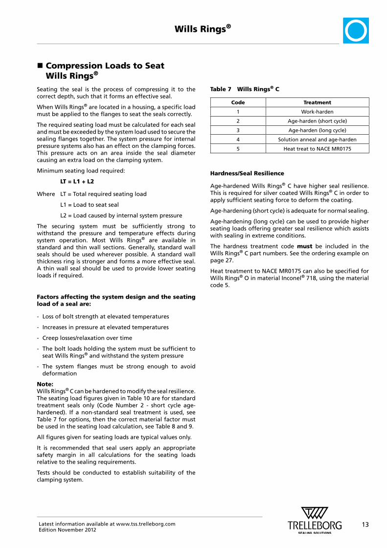
Table 7 Wills Rings® C
Code Treatment
1 Work-harden
2 Age-harden (short cycle)
3 Age-harden (long cycle)
4 Solution anneal and age-harden
5 Heat treat to NACE MR0175
Hardness/Seal Resilience
Age-hardened Wills Rings® C have higher seal resilience. This is required for silver coated Wills Rings® C in order to apply sufficient seating force to deform the coating.
Age-hardening (short cycle) is adequate for normal sealing.
Age-hardening (long cycle) can be used to provide higher seating loads offering greater seal resilience which assists with sealing in extreme conditions.
The hardness treatment code must be included in the Wills Rings® C part numbers. See the ordering example on page 27.
Heat treatment to NACE MR0175 can also be specified for Wills Rings® O in material Inconel® 718, using the material code 5.

14 Latest information available at www.tss.trelleborg.comEdition November 2012
Wills Rings®
� Calculating Seating Loads
The compressive load required to correctly seat specific Wills Rings® in the recommended groove depends on the seal diameter, seal free height, wall thickness and seal material according to the following expression:
L1 = M x K x Dm x π
where L1 = Load to seat the seal (N)
M = Material factor (see Table 8 or Table 9)
K = Load in N/mm seal circumference (see Table 10)
Dm = Median (sealing) diameter of the seal, da - d2 (mm)
π = Pythagoras constant (3.142)
Table 8 Material Factor Wills Rings® O
Material Factor M
Stainless steel AISI 316L (1.4435) 1.00
Stainless steel AISI 321 (1.4541) 1.00
Inconel® 600 1.10
Inconel® 718 1.10
Mild steel 0.75
Copper 0.75
Table 9 Material Factor Wills Rings® C Condition
Material Factor M
Inconel® X750 0.85
Inconel® 718 1.00
Note: Use M x 0.75 for work hardenUse M x 1.20 for age-harden (long cycle)
Table 10 Compressive Load for Standard Wall Wills Rings®
Cross Section Size Code
Wills Rings® O Wills Rings® C
Wall Thickness Seating Load Circumference
Wall Thickness Seating Load Circumference
mm inch mm inch N/mm lb/inch mm inch N/mm lb/inch
0.89 0.035 thin J 0.15 0.006 100 571 - - -
1.59 0.063 std A 0.36 0.014 161 919 0.25 0.010 51 291
thin K 0.15 0.010 98 560 0.15 0.006 15 86
2.38 0.094 std B 0.46 0.018 198 1131 0.38 0.015 69 394
thin L 0.25 0.010 52 297 0.25 0.010 28 160
3.18 0.125 std C 0.51 0.020 176 1,005 0.51 0.020 100 571
thin M 0.25 0.010 65 371 0.38 0.015 62 354
3.97 0.156 std D 0.64 0.025 253 1,445 0.61 0.024 111 634
thin N 0.25 0.010 46 263 0.41 0.016 46 263
4.76 0.187 std E 0.81 0.032 280 1,599 0.76 0.030 141 805
thin O 0.25 0.010 37 212 0.51 0.020 63 360
6.35 0.250 std F 1.02 0.040 100 571 - - - -
thin P 0.51 0.020 52 297 0.64 0.025 66 377
7.94 0.313 std G 1.27 0.050 330 1,884 - - - -
9.53 0.375 std H 1.52 0.060 380 2,170 - - - -
thin R 0.51 0.020 85 485 - - - -

15Latest information available at www.tss.trelleborg.comEdition November 2012
Wills Rings®
0
20000
40000
60000
80000
0 0.1
Displacement mm
Load N O ringC seal
C seal Springback = 0.09mm
Metal Seal Comparison Load vs. Deflection Graph for 2.38mm, 0.094 inch Cross-Section Standard Wall,
102.4mm, 4.031 inch OD
0.2 0.3 0.4 0.5 0.6
Figure 10 Graph detailing load vs. deflection comparison of two Wills Rings® types
Note:It is not recommended to compress the seal less than the recommended amount in order to reduce the amount of load required to seat the seal. Using deeper grooves to reduce seating load could have an adverse effect on sealing efficiency. If lower seating loads are required, the correct seal type should be chosen with the correct coating.
The compressive load required to correctly seat specific Wills Rings® in the recommended groove depends on the seal type, seal diameter, free height, wall thickness and seal material, as described on the previous page.
Figure 10 is a graph showing how seal types compare to each other for a given seal cross section, wall thickness and
diameter. Typically standard wall Wills Rings® O will require twice the seating load of standard wall Wills Rings® C.
Table 10 on the previous page gives typical seating loads for each type and cross section of Wills Rings® and the graph below demonstrates how these measurements are taken.

16 Latest information available at www.tss.trelleborg.comEdition November 2012
Wills Rings®
� Groove Designs
There are several types of groove which may be employed to house Wills Rings® depending upon the application and the system requirements, see Figure 12.
13.1 Closed groove
The seal is enclosed on its inside and outside diameters.
13.2 Open groove
The seal is enclosed by a groove wall opposing the pressure direction. For example, for internal pressure the groove wall is on the outside of the seal.
13.3 Retainer plate
If no groove can be constructed, then a plate of equal depth to the groove can be used to provide support to the seal.
Figure 11 Example of Wills Rings® with its groove
Closed Groove
Open Groove
Retainer Plate
Figure 12 Common installation configurations for Wills Rings®
All installations above show Wills Rings® O installations.
The same housings can be used for Wills Rings® C installations.
See Figure 13 and comments for Wills Rings® O within automotive groove.
17Latest information available at www.tss.trelleborg.comEdition November 2012
Wills Rings®
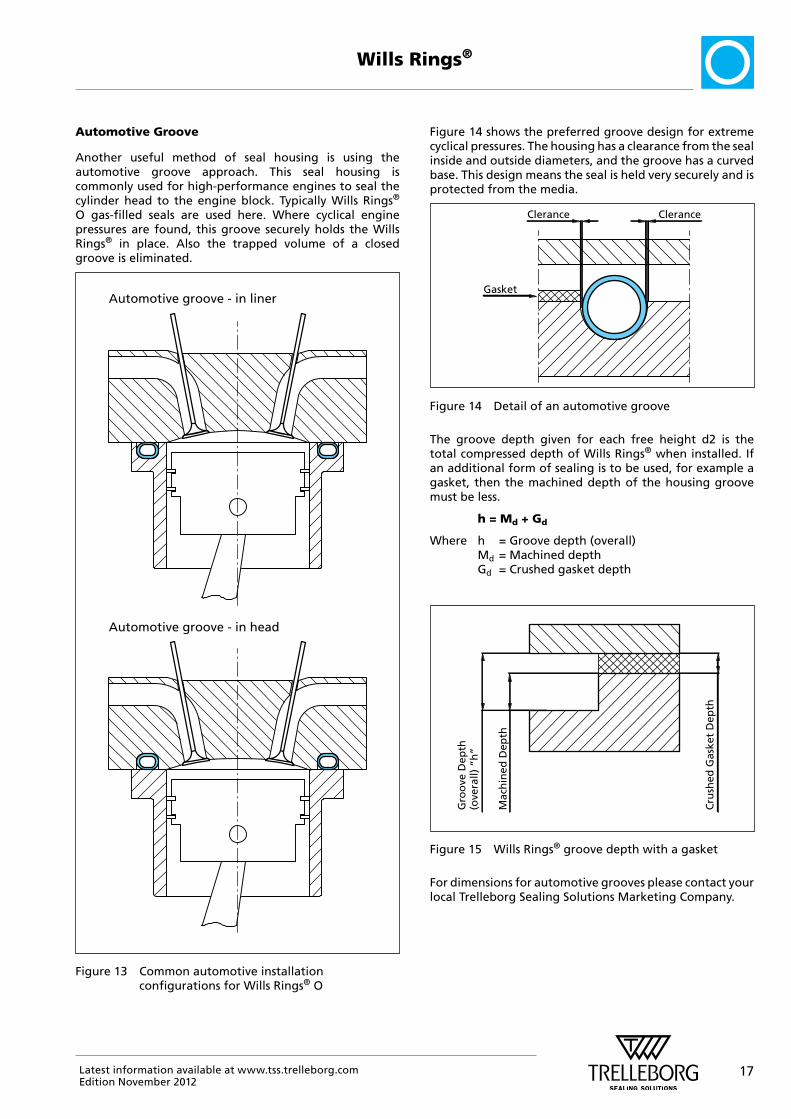
Automotive Groove
Another useful method of seal housing is using the automotive groove approach. This seal housing is commonly used for high-performance engines to seal the cylinder head to the engine block. Typically Wills Rings® O gas-filled seals are used here. Where cyclical engine pressures are found, this groove securely holds the Wills Rings® in place. Also the trapped volume of a closed groove is eliminated.
Automotive groove - in liner
Automotive groove - in head
Figure 13 Common automotive installation configurations for Wills Rings® O
Figure 14 shows the preferred groove design for extreme cyclical pressures. The housing has a clearance from the seal inside and outside diameters, and the groove has a curved base. This design means the seal is held very securely and is protected from the media.
Clerance Clerance
Gasket
Figure 14 Detail of an automotive groove
The groove depth given for each free height d2 is the total compressed depth of Wills Rings® when installed. If an additional form of sealing is to be used, for example a gasket, then the machined depth of the housing groove must be less.
h = Md + Gd
Where h = Groove depth (overall) Md = Machined depth Gd = Crushed gasket depth
Cru
shed
Gas
ket
Dep
th
Mac
hin
ed D
epth
Gro
ove
Dep
th(o
vera
ll) “
h”
Figure 15 Wills Rings® groove depth with a gasket
For dimensions for automotive grooves please contact your local Trelleborg Sealing Solutions Marketing Company.

18 Latest information available at www.tss.trelleborg.comEdition November 2012
Wills Rings®
� Part Numbers and Ordering Instructions in Metric
Installation Recommendations for Internal Pressure Sealing
d2
d2
h
Øda
Øda
Ød7
b4
r
PP
ClosedGroove
OpenGroove
Wills Rings® O Type MOT
Wills Rings® C Type MCX
Figure 16 Installation drawing for internal pressure
Table 11 Installation Dimensions for Internal Pressure
Free Height
d2 mm
Wills Rings®
0
Free Height Mat. Codes
Stand. Thin
Type
C
Free Height Mat. Codes
Stand. Thin
Groove Depth
h
Groove Width 1)
b4 min.
Wills Rings®
O 2)
Øda
Groove Diameter d7,
unplated only 3)
= da + clearance + tolerance
Radius
rmax
mm
Wills Rings®
Springback
O
only
C
only
0.89 J - 0.58 +0.08 1.25 8-50 da +0.10 +0.05 0.25 0.01 -
-0
1.59 A A 1.32 +0.08 2.25 12-150 da +0.10 +0.05 0.40 0.02 0.06
K K -0 0.03 0.07
2.38 B B 1.83 +0.08 3.00 25-500 da +0.18 +0.12 0.50 0.04 0.09
L L -0 50-500 0.06 0.11
3.18 C C 2.54 +0.13 4.00 60-1,000 da +0.18 +0.12 0.75 0.05 0.12
M M -0 0.11 0.14
3.97 D D 3.05 +0.13 5.00 100-1,250 da +0.18 +0.12 1.25 0.06 0.11
N N -0 0.13 0.16
4.76 E E 3.68 +0.13 6.00 115-1,500 da +0.25 +0.12 1.50 0.08 0.12
O O -0 150-1,500 0.17 0.23
6.35 F - 5.08 +0.13 8.00 125-2,000 da +0.25 +0.12 1.50 0.10 0.27
P P -0 0.14 -
7.94 G - 6.35 +0.13 10.00 500-2,500 da +0.38 +0.12 1.50 0.08 -
-0
9.53 H - 7.92 +0.13 12.00 750-3,000 da +0.38 +0.12 1.50 0.08 -
R - -0 0.09
Notes: 1) Minimum value. Recommended groove width 1.5 x d2. 2) For Wills Rings® C diameter size ranges see page 24 (Table 18). 3) Calculate exact groove/seal Ø by the expression: d7 = da + (2 x maximum coating thickness) + clearance (+ tol.)
= da + CTCV page 25 (Table 19), for clearance tolerance correction value)
Example: 3.18 mm Wills Rings® C with three layers of plating d7 = da + (2 x 3 layer coating = 2 x 0.085 mm = 0.170 mm) + clearance (+ tol.)
= da + 0.170 + clearance (+ tol.) = da + 0.170 + 0.18 (+0.12)
19Latest information available at www.tss.trelleborg.comEdition November 2012
Wills Rings®
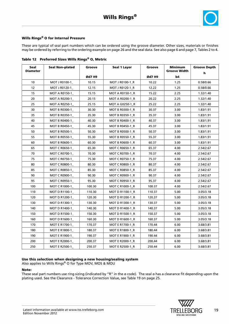
Wills Rings® O for Internal Pressure
These are typical of seal part numbers which can be ordered using the groove diameter. Other sizes, materials or finishes may be ordered by referring to the ordering example on page 26 and the seal data. See also page 6 and page 7, Tables 2 to 4.
Table 12 Preferred Sizes Wills Rings® O, Metric
Seal Diameter
Seal Non–plated Groove
Ød7 H9
Seal 1 Layer Groove
Ød7 H9
Minimum Groove Width
b4
Groove Depth
h
10 MOT J R0100-1_ 10.15 MOT J R0100-1_R 10.22 1.25 0.58/0.66
12 MOT J R0120-1_ 12.15 MOT J R0120-1_R 12.22 1.25 0.58/0.66
15 MOT A R0150-1_ 15.15 MOT A R0150-1_R 15.22 2.25 1.32/1.40
20 MOT A R0200-1_ 20.15 MOT A R0200-1_R 20.22 2.25 1.32/1.40
25 MOT A R0250-1_ 25.15 MOT A G0250-1_R 25.22 2.25 1.32/1.40
30 MOT B R0300-1_ 30.30 MOT B R0300-1_R 30.37 3.00 1.83/1.91
35 MOT B R0350-1_ 35.30 MOT B R0350-1_R 35.37 3.00 1.83/1.91
40 MOT B R0400-1_ 40.30 MOT B R0400-1_R 40.37 3.00 1.83/1.91
45 MOT B R0450-1_ 45.30 MOT B R0450-1_R 45.37 3.00 1.83/1.91
50 MOT B R0500-1_ 50.30 MOT B R0500-1_R 50.37 3.00 1.83/1.91
55 MOT B R0550-1_ 55.30 MOT B R0550-1_R 55.37 3.00 1.83/1.91
60 MOT B R0600-1_ 60.30 MOT B R0600-1_R 60.37 3.00 1.83/1.91
65 MOT C R0650-1_ 65.30 MOT C R0650-1_R 65.37 4.00 2.54/2.67
70 MOT C R0700-1_ 70.30 MOT C R0700-1_R 70.37 4.00 2.54/2.67
75 MOT C R0750-1_ 75.30 MOT C R0750-1_R 75.37 4.00 2.54/2.67
80 MOT C R0800-1_ 80.30 MOT C R0800-1_R 80.37 4.00 2.54/2.67
85 MOT C R0850-1_ 85.30 MOT C R0850-1_R 85.37 4.00 2.54/2.67
90 MOT C R0900-1_ 90.30 MOT C R0900-1_R 90.37 4.00 2.54/2.67
95 MOT C R0950-1_ 95.30 MOT C R0950-1_R 95.37 4.00 2.54/2.67
100 MOT C R1000-1_ 100.30 MOT C R1000-1_R 100.37 4.00 2.54/2.67
110 MOT D R1100-1_ 110.30 MOT D R1100-1_R 110.37 5.00 3.05/3.18
120 MOT D R1200-1_ 120.30 MOT D R1200-1_R 120.37 5.00 3.05/3.18
130 MOT D R1300-1_ 130.30 MOT D R1300-1_R 130.37 5.00 3.05/3.18
140 MOT D R1400-1_ 140.30 MOT D R1400-1_R 140.37 5.00 3.05/3.18
150 MOT D R1500-1_ 150.30 MOT D R1500-1_R 150.37 5.00 3.05/3.18
160 MOT D R1600-1_ 160.30 MOT D R1600-1_R 160.37 5.00 3.05/3.18
170 MOT E R1700-1_ 170.37 MOT E R1700-1_R 170.44 6.00 3.68/3.81
180 MOT E R1800-1_ 180.37 MOT E R1800-1_R 180.44 6.00 3.68/3.81
190 MOT E R1900-1_ 190.37 MOT E R1900-1_R 190.44 6.00 3.68/3.81
200 MOT E R2000-1_ 200.37 MOT E R2000-1_R 200.44 6.00 3.68/3.81
250 MOT E R2500-1_ 250.37 MOT E R2500-1_R 250.44 6.00 3.68/3.81
Use this selection when designing a new housing/sealing systemAlso applies to Wills Rings® O for Type MOV, MOS & MOU
Note: These seal part numbers use ring sizing (indicated by “R” in the ø code). The seal ø has a clearance fit depending upon the plating used. See the Clearance - Tolerance Correction Value, see Table 19 on page 25.

20 Latest information available at www.tss.trelleborg.comEdition November 2012
Wills Rings®
Wills Rings® C for Internal Pressure
These are typical of seal part numbers which can be ordered using the groove diameter. Other sizes, materials or finishes may be ordered by referring to the order C example on page 27 and the seal data. See also page 6 and page 7, Tables 2 to 4.
Table 13 Preferred Sizes Wills Rings® C, Metric
Seal Diameter
Seal Non–plated Groove
Ød7 H9
Seal 1 Layer Groove
Ød7 H9
Minimum Groove Width
b4
Groove Depth
h
20 MCX A R0200-1_2 20.15 MCX A R0200-1_R2 20.22 2.25 1.32/1.40
25 MCX A R0250-1_2 25.15 MCX A R0250-1_R2 25.22 2.25 1.32/1.40
30 MCX A R0300-1_2 30.15 MCX A R0300-1_R2 30.22 2.25 1.32/1.40
35 MCX A R0350-1_2 35.15 MCX A R0350-1_R2 35.22 2.25 1.32/1.40
40 MCX A R0400-1_2 40.15 MCX A R0400-1_R2 40.22 2.25 1.32/1.40
50 MCX A R0500-1_2 50.15 MCX A R0500-1_R2 50.22 2.25 1.32/1.40
30 MCX B R0300-1_2 30.30 MCX B R0300-1_R2 30.37 3.00 1.83/1.91
40 MCX B R0400-1_2 40.30 MCX B R0400-1_R2 40.37 3.00 1.83/1.91
50 MCX B R0500-1_2 50.30 MCX B R0500-1_R2 50.37 3.00 1.83/1.91
60 MCX B R0600-1_2 60.30 MCX B R0600-1_R2 60.37 3.00 1.83/1.91
70 MCX B R0700-1_2 70.30 MCX B R0700-1_R2 70.37 3.00 1.83/1.91
80 MCX B R0800-1_2 80.30 MCX B R0800-1_R2 80.37 3.00 1.83/1.91
90 MCX B R0900-1_2 90.30 MCX B R0900-1_R2 90.37 3.00 1.83/1.91
70 MCX C R0700-1_2 70.30 MCX C R0700-1_R2 70.37 4.00 2.54/2.67
80 MCX C R0800-1_2 80.30 MCX C R0800-1_R2 80.37 4.00 2.54/2.67
90 MCX C R0900-1_2 90.30 MCX C R0900-1_R2 90.37 4.00 2.54/2.67
100 MCX C R1000-1_2 100.30 MCX C R1000-1_R2 100.37 4.00 2.54/2.67
110 MCX C R1100-1_2 110.30 MCX C R1100-1_R2 110.37 4.00 2.54/2.67
150 MCX C R1500-1_2 150.30 MCX C R1500-1_R2 150.37 4.00 2.54/2.67
110 MCX D R1100-1_2 110.30 MCX D R1100-1_R2 110.37 5.00 3.05/3.18
120 MCX D R1200-1_2 120.30 MCX D R1200-1_R2 120.37 5.00 3.05/3.18
130 MCX D R1300-1_2 130.30 MCX D R1300-1_R2 130.37 5.00 3.05/3.18
140 MCX D R1400-1_2 140.30 MCX D R1400-1_R2 140.37 5.00 3.05/3.18
150 MCX D R1500-1_2 150.30 MCX D R1500-1_R2 150.37 5.00 3.05/3.18
160 MCX D R1600-1_2 160.30 MCX D R1600-1_R2 160.37 5.00 3.05/3.18
160 MCX E R1600-1_2 160.37 MCX E R1600-1_R2 160.44 6.00 3.68/3.81
170 MCX E R1700-1_2 170.37 MCX E R1700-1_R2 170.44 6.00 3.68/3.81
180 MCX E R1800-1_2 180.37 MCX E R1800-1_R2 180.44 6.00 3.68/3.81
190 MCX E R1900-1_2 190.37 MCX E R1900-1_R2 190.44 6.00 3.68/3.81
200 MCX E R2000-1_2 200.37 MCX E R2000-1_R2 200.44 6.00 3.68/3.81
160 MCX P R1600-1_2 160.37 MCX P R1600-1_R2 160.44 8.00 5.08/5.21
170 MCX P R1700-1_2 170.37 MCX P R1700-1_R2 170.44 8.00 5.08/5.21
180 MCX P R1800-1_2 180.37 MCX P R1800-1_R2 180.44 8.00 5.08/5.21
190 MCX P R1900-1_2 190.37 MCX P R1900-1_R2 190.44 8.00 5.08/5.21
200 MCX P R2000-1_2 200.37 MCX P R2000-1_R2 200.44 8.00 5.08/5.21
Use this selection when designing a new housing/sealing system. Note: These seal part numbers use ring sizing (indicated by “R” in the ø code). The seal ø has a clearance fit depending upon the plating used. See the Clearance - Tolerance Correction Value, see Table 19 on page 25.
21Latest information available at www.tss.trelleborg.comEdition November 2012
Wills Rings®
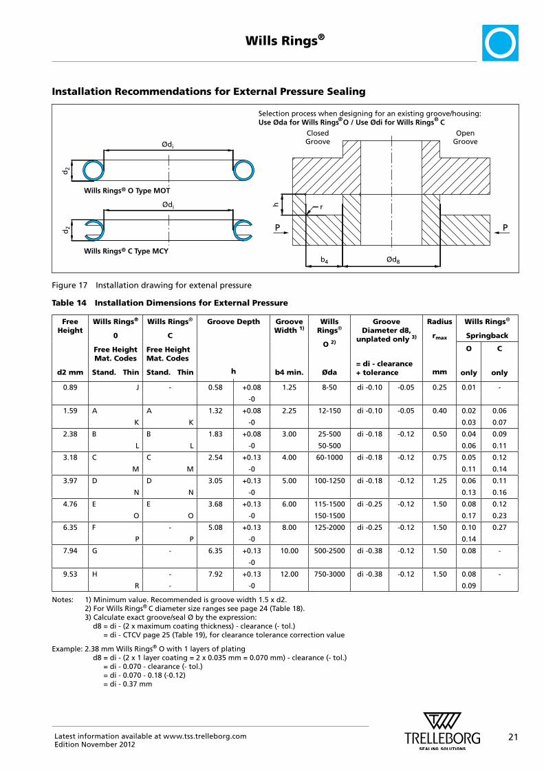
Installation Recommendations for External Pressure Sealing
Wills Rings® O Type MOT
Wills Rings® C Type MCY
h
Ød8b4
r
P P
ClosedGroove
OpenGroove
d2
d2
Ødi
Ødi
Selection process when designing for an existing groove/housing: Use Øda for Wills Rings O / Use Ødi for Wills Rings C® ®
Figure 17 Installation drawing for extenal pressure
Table 14 Installation Dimensions for External Pressure
Free Height
d2 mm
Wills Rings®
0
Free Height Mat. Codes
Stand. Thin
Wills Rings®
C
Free Height Mat. Codes
Stand. Thin
Groove Depth
h
Groove Width 1)
b4 min.
Wills Rings®
O 2)
Øda
Groove Diameter d8,
unplated only 3)
= di - clearance + tolerance
Radius
rmax
mm
Wills Rings®
Springback
O
only
C
only
0.89 J - 0.58 +0.08 1.25 8-50 di -0.10 -0.05 0.25 0.01 -
-0
1.59 A A 1.32 +0.08 2.25 12-150 di -0.10 -0.05 0.40 0.02 0.06
K K -0 0.03 0.07
2.38 B B 1.83 +0.08 3.00 25-500 di -0.18 -0.12 0.50 0.04 0.09
L L -0 50-500 0.06 0.11
3.18 C C 2.54 +0.13 4.00 60-1000 di -0.18 -0.12 0.75 0.05 0.12
M M -0 0.11 0.14
3.97 D D 3.05 +0.13 5.00 100-1250 di -0.18 -0.12 1.25 0.06 0.11
N N -0 0.13 0.16
4.76 E E 3.68 +0.13 6.00 115-1500 di -0.25 -0.12 1.50 0.08 0.12
O O -0 150-1500 0.17 0.23
6.35 F - 5.08 +0.13 8.00 125-2000 di -0.25 -0.12 1.50 0.10 0.27
P P -0 0.14
7.94 G - 6.35 +0.13 10.00 500-2500 di -0.38 -0.12 1.50 0.08 -
-0
9.53 H - 7.92 +0.13 12.00 750-3000 di -0.38 -0.12 1.50 0.08 -
R - -0 0.09
Notes: 1) Minimum value. Recommended is groove width 1.5 x d2. 2) For Wills Rings® C diameter size ranges see page 24 (Table 18). 3) Calculate exact groove/seal Ø by the expression: d8 = di - (2 x maximum coating thickness) - clearance (- tol.)
= di - CTCV page 25 (Table 19), for clearance tolerance correction value
Example: 2.38 mm Wills Rings® O with 1 layers of plating d8 = di - (2 x 1 layer coating = 2 x 0.035 mm = 0.070 mm) - clearance (- tol.)
= di - 0.070 - clearance (- tol.) = di - 0.070 - 0.18 (-0.12) = di - 0.37 mm

22 Latest information available at www.tss.trelleborg.comEdition November 2012
Wills Rings®
Wills Rings® O for External Pressure
These are typical of seal part numbers which can be ordered using the groove diameter. Other sizes. materials or finishes may be ordered by referring to the ordering example on page 26 and the seal data. See also page 6 and page 7, Tables 2 to 4.
Table 15 Preferred Sizes Wills Rings® O, Metric
Seal Diameter
Seal Non–plated Groove ID
Ød8 h9
Seal 1 Layer Groove ID
Ød8 h9
Minimum Groove Width
b4
Groove Depth
h
10 MOT J R0100-1_ 8.07 MOT J R0100-1_R 8.00 1.25 0.58/0.66
12 MOT J R0120-1_ 10.07 MOT J R0120-1_R 10.00 1.25 0.58/0.66
15 MOT A R0150-1_ 11.67 MOT A R0150-1_R 11.60 2.25 1.32/1.40
20 MOT A R0200-1_ 16.67 MOT A R0200-1_R 16.60 2.25 1.32/1.40
25 MOT A R0250-1_ 21.67 MOT A G0250-1_R 21.60 2.25 1.32/1.40
30 MOT B R0300-1_ 24.94 MOT B R0300-1_R 24.87 3.00 1.83/1.91
35 MOT B R0350-1_ 29.94 MOT B R0350-1_R 29.87 3.00 1.83/1.91
40 MOT B R0400-1_ 34.94 MOT B R0400-1_R 35.87 3.00 1.83/1.91
45 MOT B R0450-1_ 39.94 MOT B R0450-1_R 39.87 3.00 1.83/1.91
50 MOT B R0500-1_ 44.94 MOT B R0500-1_R 45.87 3.00 1.83/1.91
55 MOT B R0550-1_ 49.94 MOT B R0550-1_R 49.87 3.00 1.83/1.91
60 MOT B R0600-1_ 54.94 MOT B R0600-1_R 54.87 3.00 1.83/1.91
65 MOT C R0650-1_ 58.34 MOT C R0650-1_R 58.27 4.00 2.54/2.67
70 MOT C R0700-1_ 63.34 MOT C R0700-1_R 63.27 4.00 2.54/2.67
75 MOT C R0750-1_ 68.34 MOT C R0750-1_R 68.27 4.00 2.54/2.67
80 MOT C R0800-1_ 73.34 MOT C R0800-1_R 73.27 4.00 2.54/2.67
85 MOT C R0850-1_ 78.34 MOT C R0850-1_R 78.27 4.00 2.54/2.67
90 MOT C R0900-1_ 83.34 MOT C R0900-1_R 83.27 4.00 2.54/2.67
95 MOT C R0950-1_ 88.34 MOT C R0950-1_R 88.27 4.00 2.54/2.67
100 MOT C R1000-1_ 93.34 MOT C R1000-1_R 93.27 4.00 2.54/2.67
110 MOT D R1100-1_ 101.76 MOT D R1100-1_R 101.69 5.00 3.05/3.18
120 MOT D R1200-1_ 111.76 MOT D R1200-1_R 110.69 5.00 3.05/3.18
130 MOT D R1300-1_ 121.76 MOT D R1300-1_R 120.69 5.00 3.05/3.18
140 MOT D R1400-1_ 131.76 MOT D R1400-1_R 130.69 5.00 3.05/3.18
150 MOT D R1500-1_ 141.76 MOT D R1500-1_R 140.69 5.00 3.05/3.18
160 MOT D R1600-1_ 151.76 MOT D R1600-1_R 150.69 5.00 3.05/3.18
170 MOT E R1700-1_ 160.11 MOT E R1700-1_R 160.04 6.00 3.68/3.81
180 MOT E R1800-1_ 170.11 MOT E R1800-1_R 170.04 6.00 3.68/3.81
190 MOT E R1900-1_ 180.11 MOT E R1900-1_R 180.04 6.00 3.68/3.81
200 MOT E R2000-1_ 190.11 MOT E R2000-1_R 190.04 6.00 3.68/3.81
250 MOT E R2500-1_ 240.11 MOT E R2500-1_R 240.04 6.00 3.68/3.81
Use this selection when designing a new housing/sealing system. Also applies to Wills Rings® O for Type MOW, MOS & MOU.
Note: These seal part numbers use ring sizing (indicated by “R” in the ø code) and the groove ød8. The seal ø has a clearance fit depending upon the plating used. See the Clearance - Tolerance Correction Value, see table 19 on page 25.

23Latest information available at www.tss.trelleborg.comEdition November 2012
Wills Rings®
Wills Rings® C for External Pressure
These are typical of seal part numbers which can be ordered using the groove diameter. Other sizes, materials or finishes may be ordered by referring to the order example on page 27 and the seal data. See also page 6 and page 7, Tables 2 to 4.
Table 16 Preferred Sizes Wills Rings® C, Metric
Seal Diameter
Seal Non–plated Groove ID
Ød8 h9
Seal 1 Layer Groove ID
Ød8 h9
Minimum Groove Width
b4
Groove Depth
h
20 MCY A R0200-1_2 19.85 MCY A R0200-1_R2 19.78 2.25 1.32/1.40
25 MCY A R0250-1_2 24.85 MCY A R0250-1_R2 24.78 2.25 1.32/1.40
30 MCY A R0300-1_2 29.85 MCY A R0300-1_R2 29.78 2.25 1.32/1.40
35 MCY A R0350-1_2 34.85 MCY A R0350-1_R2 34.78 2.25 1.32/1.40
40 MCY A R0400-1_2 39.85 MCY A R0400-1_R2 39.78 2.25 1.32/1.40
50 MCY A R0500-1_2 49.85 MCY A R0500-1_R2 49.78 2.25 1.32/1.40
30 MCY B R0300-1_2 29.70 MCY B R0300-1_R2 29.63 3.00 1.83/1.91
40 MCY B R0400-1_2 39.70 MCY B R0400-1_R2 39.63 3.00 1.83/1.91
50 MCY B R0500-1_2 49.70 MCY B R0500-1_R2 49.63 3.00 1.83/1.91
60 MCY B R0600-1_2 59.70 MCY B R0600-1_R2 59.63 3.00 1.83/1.91
70 MCY B R0700-1_2 69.70 MCY B R0700-1_R2 69.63 3.00 1.83/1.91
80 MCY B R0800-1_2 79.70 MCY B R0800-1_R2 79.63 3.00 1.83/1.91
90 MCY B R0900-1_2 89.70 MCY B R0900-1_R2 89.63 3.00 1.83/1.91
70 MCY C R0700-1_2 69.70 MCY C R0700-1_R2 69.63 4.00 2.54/2.67
80 MCY C R0800-1_2 79.70 MCY C R0800-1_R2 79.63 4.00 2.54/2.67
90 MCY C R0900-1_2 89.70 MCY C R0900-1_R2 89.63 4.00 2.54/2.67
100 MCY C R1000-1_2 99.70 MCY C R1000-1_R2 99.63 4.00 2.54/2.67
110 MCY C R1100-1_2 109.70 MCY C R1100-1_R2 109.63 4.00 2.54/2.67
150 MCY C R1500-1_2 149.70 MCY C R1500-1_R2 149.63 4.00 2.54/2.67
110 MCY D R1100-1_2 109.70 MCY D R1100-1_R2 109.63 5.00 3.05/3.18
120 MCY D R1200-1_2 119.70 MCY D R1200-1_R2 119.63 5.00 3.05/3.18
130 MCY D R1300-1_2 129.70 MCY D R1300-1_R2 129.63 5.00 3.05/3.18
140 MCY D R1400-1_2 139.70 MCY D R1400-1_R2 139.63 5.00 3.05/3.18
150 MCY D R1500-1_2 149.70 MCY D R1500-1_R2 149.63 5.00 3.05/3.18
160 MCY D R1600-1_2 159.70 MCY D R1600-1_R2 159.63 5.00 3.05/3.18
160 MCY E R1600-1_2 159.63 MCY E R1600-1_R2 159.56 6.00 3.68/3.81
170 MCY E R1700-1_2 169.63 MCY E R1700-1_R2 169.56 6.00 3.68/3.81
180 MCY E R1800-1_2 179.63 MCY E R1800-1_R2 179.56 6.00 3.68/3.81
190 MCY E R1900-1_2 189.63 MCY E R1900-1_R2 189.56 6.00 3.68/3.81
200 MCY E R2000-1_2 199.63 MCY E R2000-1_R2 199.56 6.00 3.68/3.81
160 MCY P R1600-1_2 159.63 MCY P R1600-1_R2 159.56 8.00 5.08/5.21
170 MCY P R1700-1_2 169.63 MCY P R1700-1_R2 169.56 8.00 5.08/5.21
180 MCY P R1800-1_2 179.63 MCY P R1800-1_R2 179.56 8.00 5.08/5.21
190 MCY P R1900-1_2 189.63 MCY P R1900-1_R2 189.56 8.00 5.08/5.21
200 MCY P R2000-1_2 199.63 MCY P R2000-1_R2 199.56 8.00 5.08/5.21
Use this selection when designing a new housing/sealing system. Note: These seal part numbers use ring sizing (indicated by “R” in the ø code) and the groove ød8. The seal ø has a clearance fit depending upon the plating used. See the Clearance - Tolerance Correction Value, see table 19 on page 25.
24 Latest information available at www.tss.trelleborg.comEdition November 2012
Wills Rings®
� Metric Part Numbers and Ordering Instructions
Metric Size Ranges and Free Heights
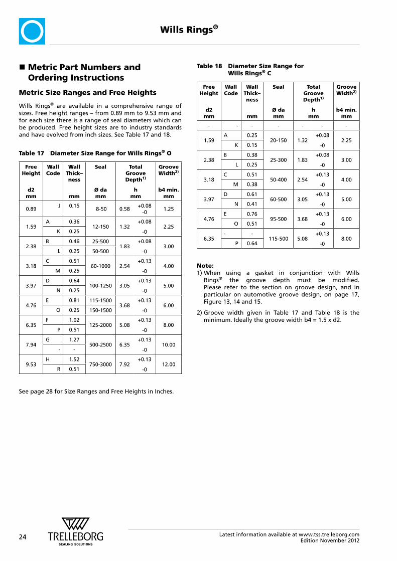
Wills Rings® are available in a comprehensive range of sizes. Free height ranges – from 0.89 mm to 9.53 mm and for each size there is a range of seal diameters which can be produced. Free height sizes are to industry standards and have evolved from inch sizes. See Table 17 and 18.
Table 17 Diameter Size Range for Wills Rings® O
Free Height
d2
mm
Wall Code
Wall Thick– ness
mm
Seal
Ø da mm
Total Groove Depth1)
h mm
Groove Width2)
b4 min. mm
0.89J 0.15
8-50 0.58+0.08
-01.25
1.59A 0.36
12-150 1.32+0.08
-02.25
K 0.25
2.38B 0.46 25-500
1.83+0.08
-03.00
L 0.25 50-500
3.18C 0.51
60-1000 2.54+0.13
-04.00
M 0.25
3.97D 0.64
100-1250 3.05+0.13
-05.00
N 0.25
4.76E 0.81 115-1500
3.68+0.13
-06.00
O 0.25 150-1500
6.35F 1.02
125-2000 5.08+0.13
-08.00
P 0.51
7.94G 1.27
500-2500 6.35+0.13
-010.00
- -
9.53H 1.52
750-3000 7.92+0.13
-012.00
R 0.51
See page 28 for Size Ranges and Free Heights in Inches.
Table 18 Diameter Size Range for Wills Rings® C
Free Height
d2
mm
Wall Code
Wall Thick– ness
mm
Seal
Ø da mm
Total Groove Depth1)
h mm
Groove Width2)
b4 min. mm
- - - - - - -
1.59A 0.25
20-150 1.32+0.08
-02.25
K 0.15
2.38B 0.38
25-300 1.83+0.08
-03.00
L 0.25
3.18C 0.51
50-400 2.54+0.13
-04.00
M 0.38
3.97D 0.61
60-500 3.05+0.13
-05.00
N 0.41
4.76E 0.76
95-500 3.68+0.13
-06.00
O 0.51
6.35- -
115-500 5.08+0.13
-08.00
P 0.64
Note: 1) When using a gasket in conjunction with Wills
Rings® the groove depth must be modified. Please refer to the section on groove design, and in particular on automotive groove design, on page 17, Figure 13, 14 and 15.
2) Groove width given in Table 17 and Table 18 is the minimum. Ideally the groove width b4 = 1.5 x d2.
25Latest information available at www.tss.trelleborg.comEdition November 2012
Wills Rings®
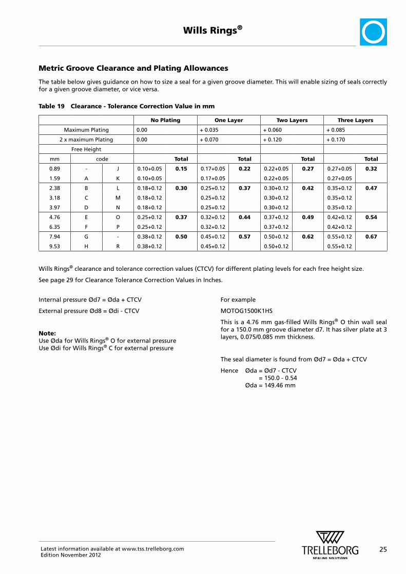
Metric Groove Clearance and Plating Allowances
The table below gives guidance on how to size a seal for a given groove diameter. This will enable sizing of seals correctly for a given groove diameter, or vice versa.
Table 19 Clearance - Tolerance Correction Value in mm
No Plating One Layer Two Layers Three Layers
Maximum Plating 0.00 + 0.035 + 0.060 + 0.085
2 x maximum Plating 0.00 + 0.070 + 0.120 + 0.170
Free Height
mm code Total Total Total Total
0.89 - J 0.10+0.05 0.15 0.17+0.05 0.22 0.22+0.05 0.27 0.27+0.05 0.32
1.59 A K 0.10+0.05 0.17+0.05 0.22+0.05 0.27+0.05
2.38 B L 0.18+0.12 0.30 0.25+0.12 0.37 0.30+0.12 0.42 0.35+0.12 0.47
3.18 C M 0.18+0.12 0.25+0.12 0.30+0.12 0.35+0.12
3.97 D N 0.18+0.12 0.25+0.12 0.30+0.12 0.35+0.12
4.76 E O 0.25+0.12 0.37 0.32+0.12 0.44 0.37+0.12 0.49 0.42+0.12 0.54
6.35 F P 0.25+0.12 0.32+0.12 0.37+0.12 0.42+0.12
7.94 G - 0.38+0.12 0.50 0.45+0.12 0.57 0.50+0.12 0.62 0.55+0.12 0.67
9.53 H R 0.38+0.12 0.45+0.12 0.50+0.12 0.55+0.12
Wills Rings® clearance and tolerance correction values (CTCV) for different plating levels for each free height size.
See page 29 for Clearance Tolerance Correction Values in Inches.
Internal pressure Ød7 = Øda + CTCV
External pressure Ød8 = Ødi - CTCV
Note:Use Øda for Wills Rings® O for external pressure Use Ødi for Wills Rings® C for external pressure
For example
MOTOG1500K1HS
This is a 4.76 mm gas-filled Wills Rings® O thin wall seal for a 150.0 mm groove diameter d7. It has silver plate at 3 layers, 0.075/0.085 mm thickness.
The seal diameter is found from Ød7 = Øda + CTCV
Hence Øda = Ød7 - CTCV = 150.0 - 0.54 Øda = 149.46 mm

26 Latest information available at www.tss.trelleborg.comEdition November 2012
Wills Rings®
Metric Part Number Systems for Wills Rings®
Table 20 Metric Part Number System for Wills Rings® O in Metric
Seal Type
Series Free Height/ Wall Size
mm
Seal Diameter
Quality Characteristic
Code
Characteristic Number
Seal Material Coating Material
Treat-ment
M O
M Metal
O O-Ring profile
S Solid
T Gas–filled
U Non– Pressurized
V Pressure vented ID
W Pressure vented OD
Standard wall
A 1.59 0.36
B 2.38 0.46
C 3.18 0.51
D 3.97 0.64
E 4.76 0.81
F 6.35 1.02
G 7.94 1.27
H 9.53 1.52
Thin wall
J 0.89 0.15
K 1.59 0.25
L 2.38 0.25
M 3.18 0.25
N 3.97 0.25
O 4.76 0.25
P 6.35 0.51
R 9.53 0.51
Diameter x 10 (up to) 999.9)
G - - - - this is the groove outside diameter Ød7 x 10
Use the groove method only for internal pressure/ external sealing
R - - - - this is the ring outside dia.
Øda x 10
”-” Standard Quality
”K” X–Ray required
”A” Aerospace use
1 = Standard
B Mild steel
H Stainless Steel AISI 316L (1.4435)
E Stainless Steel AISI 321 (1.4541)
M Inconel® 600
L Inconel® 718
O Copper
Q Nickel
O Copper
I Gold
N Indium
R Silver One layer
U Silver Two layers
S Silver Three layers
5 =
Heat treatment to NACE MR0175 (Inconel® 718 only)
Notes: MOV/MOW (pressure vented type) seal not available in 0.89 mm free height. Use MOT type or increase to a 1.59 mm size instead. Other non-standard plating/coating options are available. Ask your local Trelleborg Marketing Company for further details. Select Quality Characteristic Code K for Thin wall rings.
Example 1
M O T C G 1 0 0 0 - 1 H S
Wills Rings® O gas filled seal
Free Height 3.18 mm Standard wall (0.51 mm)
Groove diameter Ød7 = 100.00 mm
Therefore groove diameter Øda = 100.00 - CTCV = 100.00 - 0.47 Øda = 99.53 mm
Quality Characteristic code
- is standard Characteristic number
1 is standard
Material Stainless Steel 316L Silver at three layers
Example 2
Material Stainless Steel 321 Silver at one layer
M O T B R 0 6 9 8 - 1 E R
Wills Rings® O gas filled seal Seal on groove inside diameter Ød8 for external pressure
Free Height 2.38 mm Standard wall (0.46 mm)
Seal outside diameter Øda = 69.76 mm
Therefore groove diameter Ød8 = 69.76 - (2xd2) - CTCV = 69.76 - (4.76) - 0.37 Ød8 = 64.63 mm where Ødi = 65.0 mm
Quality Characteristic code
- is standard Characteristic number
1 is standard
See page 30 for part number system in Inches.

27Latest information available at www.tss.trelleborg.comEdition November 2012
Wills Rings®
Table 21 Metric Part Number System for Wills Rings® C
Seal Type Series Free Height/ Wall Size
mm
Seal Diameter Quality Characteristic
Code
Characteristic Number
Seal Material Coating Material
Treatment
M C
M Metal
C C-Ring profile
X Internal pressure
Y External pressure
Standard wall
A 1.59 0.25
B 2.38 0.38
C 3.18 0.51
D 3.97 0.61
E 4.76 0.76
Thin wall
K 1.59 0.15
L 2.38 0.25
M 3.18 0.38
N 3.97 0.41
O 4.76 0.51
P 6.35 0.64
(up to) 999.9)
G - - - - this is the groove diameter (Ød7 or ød8) x10
R - - - - this is the seal diameter (Øda or Ødi) x 10
Use outside diameter for internal pressure/outside sealing
Use inside diameter for external pressure/inside sealing
”-” Standard Quality
”A” Aerospace use
1 = Standard
L Inconel®
718
N Inconel®
X750
O Copper
I Gold
N Indium
R Silver One layer
U Silver Two layers
S Silver Three layers
1 = Work hardened
2 = Standard age hardened (short cycle)
3 = Age hardened (long cycle)
4 = Solution annealed and age hardened
5 = Heat treatment to NACE MR0175
Notes: Other non-standard plating/coating options are available.
Treatment code 5 for seal material Inconel® 718 only.
Example 1
M C X C G 1 5 0 0 - 1 N U
Wills Rings® C Internal pressure
(seal on OD)
Free Height 3.18 mm Standard wall (0.51 mm)
Groove diameter Ød7 = 150.00 mm
Therefore groove diameter Øda = 150.00 - CTCV = 150.00 - 0.42 Øda = 149.58 mm
Quality Characteristic code
- is standard Characteristic number
1 is standard
Material Inconel® X750 Silver at two layers Standard age harden (short cycle)
2
Example 2
M C Y O R 1 0 5 0 - 1 L R
Wills Rings® C External pressure
(seal on ID)
Free Height 4.76 mm Thin wall (0.51 mm)
Groove diameter Ødi = 105.00 mm
Therefore groove diameter ød8 = 105.00 - CTCV = 105.00 - 0.44 ød8 = 104.56 mm
Quality Characteristic code
- is standard Characteristic number
1 is standard
Material Inconel® 718 + Silver at one layer Standard age harden (short cycle)
2
See page 31 for part number system in Inches.

28 Latest information available at www.tss.trelleborg.comEdition November 2012
Wills Rings®
Table 22 Diameter Size Range in Inches for Wills Rings® O
Free Height
d2 inch
Wall Code
Wall
inch
Seal
Ø da inch
Total Groove Depth1)
h inch
Groove Width2)
b4 min. inch
0.035 J 0.006 0.313-2 0.023 +0.003 0.050
-0
0.063 A 0.014 0.5-6 0.052 +0.003
-0
0.089
K 0.010
0.094 B 0.018 1-20 0.072 +0.003
-0
0.118
L 0.010 2-20
0.125 C 0.020 2.5-40 0.100 +0.005
-0
0.157
M 0.010
0.156 D 0.025 4-60 0.120 +0.005
-0
0.197
N 0.010
0.187 E 0.032 4.5-60 0.145 +0.005
-0
0.236
O 0.010 6-60
0.250 F 0.040 5-80 0.200 +0.005
-0
0.315
P 0.020
0.313 G 0.050 20-100 0.250 +0.005
-0
0.394
- -
0.375 H 0.060 30-120 0.312 +0.005
-0
0.472
R 0.020
See page 24 for Size Ranges and Free Heights in Metric.
Wills Rings® are available in a comprehensive range of sizes. Free height ranges from 0.035 inch to 0.375 inch and for each size there is a range of seal diameters which can be produced. Free height sizes are industry standard and have evolved from inch sizes. See Table 22 and Table 23.
Table 23 Diameter Size Range in Inches for Wills Rings® C
Free Height
d2 inch
Wall Code
Wall
inch
Seal
Ø da inch
Total Groove Depth1)
h inch
Groove Width2)
b4 min. inch
- - - - - - -
0.063 A 0.010 0.8-6 0.052 +0.003 0.089
K 0.006 -0
0.094 B 0.015 1-12 0.072 +0.003
-0
0.118
L 0.010
0.125 C 0.020 2-16 0.100 +0.005
-0
0.157
M 0.015
0.156 D 0.024 2.4-20 0.120 +0.005
-0
0.197
N 0.016
0.187 E 0.030 3.75-20 0.145 +0.005
-0
0.236
O 0.020
0.250 - - 4.5-20 0.200 +0.005
-0
0.315
P 0.025
Note: 1) When using a gasket in conjunction with Wills
Rings® the groove depth must be modified. Please refer to the section on groove design, and in particular on automotive groove design on page 17, Figure 13, 14 and 15.
2) Groove width given in Table 22 and Table 23 is the minimum. Ideally the groove width b4 = 1.5 x d2.
� Inch Part Numbers and Ordering Instructions
Inch Size Ranges and Free Heights

29Latest information available at www.tss.trelleborg.comEdition November 2012
Wills Rings®
Inch Groove Clearance and Plating Allowances
The table below gives guidance on how to size a seal for a given groove diameter. This will enable sizing of seals correctly for a given groove diameter, or vice versa.
Table 24 Inch Clearance - Tolerance Correction Value
No Plating One Layer Two Layers Three Layers
Maximum Plating 0.00 + 0.0015 + 0.0025 + 0.0035
2 x maximum Plating 0.00 + 0.003 + 0.005 + 0.007
Free Height
inch code Total Total Total Total
0.035 - J 0.004+0.002 0.006 0.007+0.002 0.009 0.009+0.002 0.011 0.011+0.002 0.013
0.063 A K 0.004+0.002 0.007+0.002 0.009+0.002 0.011+0.002
0.094 B L 0.007+0.005 0.012 0.010+0.005 0.015 0.012+0.005 0.017 0.014+0.005 0.019
0.125 C M 0.007+0.005 0.010+0.005 0.012+0.005 0.014+0.005
0.156 D N 0.007+0.005 0.010+0.005 0.012+0.005 0.014+0.005
0.187 E O 0.010+0.005 0.015 0.013+0.005 0.018 0.015+0.005 0.020 0.017+0.005 0.022
0.250 F P 0.010+0.005 0.013+0.005 0.015+0.005 0.017+0.005
0.313 G - 0.015+0.005 0.020 0.018+0.005 0.023 0.020+0.005 0.025 0.022+0.005 0.027
0.375 H R 0.015+0.005 0.018+0.005 0.020+0.005 0.022+0.005
Wills Rings® clearance and tolerance correction values (CTCV) for different plating levels for each free height size in Inches.
See page 25 for Clearance Tolerance Correction Values in Metric.
Internal pressure Ød7 = Øda + CTCV
External pressure Ød8 = Ødi - CTCV
Note:Use Øda for Wills Rings® O for external pressure
Use Ødi for Wills Rings® C for external pressure
For example
MOTOL1200K1HS
This is a 0.187 inch gas-filled Wills Rings® O thin wall seal for a 12.00 inch seal diameter da. It has silver plate at 3 layers, 0.003 inch/0.0035 inch thickness.
The groove diameter is found from Ød7 = Øda + CTCV
Hence Ød7 = Øda + CTCV = 12.00 + 0.022
Ød7 = 12.022"

30 Latest information available at www.tss.trelleborg.comEdition November 2012
Wills Rings®
Inch Part Number Systems for Wills Rings®
Table 25 Inch Part Number System for Wills Rings® O
Seal Type Series Free Height/ Wall Size
mm
Seal Diameter
Quality Characteristic
Code
Characteristic Number
Seal Material Coating Material
Treat-ment
M O
M Metal
O O-Ring profile
S Solid
T Gas– filled
U Non– pressurized
V Pressure vented ID
W Pressure vented OD
Standard wall
A .063 .014
B .094 .018
C .125 .020
D .156 .025
E .187 .032
F .250 .040
G .313 .050
H .375 .060
Thin wall
J .035 .006
K .063 .010
L .094 .010
M .125 .010
N .156 .010
O .187 .010
P .250 .020
R .375 .020
For small diameter up to 9.999” use
S - - - - this is the seal
outside diameter Øda to three decimal places
For larger diameter above 10.000” use
L - - - - this is the seal outside diameter Øda to two decimal places
”-” Standard Quality
"K" X-Ray required
”A” Aerospace use
1 = Standard
B Mild steel
H Stainless Steel AISI 316L (1.4435)
E Stainless Steel AISI 321 (1.4541)
M Inconel® 600
L Inconel® 718
O Copper
Q Nickel
O Copper
I Gold
N Indium
R Silver 1 layer
U Silver 2 layers
S Silver 3 layers
5 = Heat treatment to NACE MR0175 (Inconel® 718 only)
Notes: MOV/MOW (Pressure Vented type) seal not available in 0.035” free height. Use MOT type or increase to a 0.063” size instead. Other non-standard plating/coating options are available. Select Quality Characteristic Code K for Thin wall rings.
Example 1
M O T B S 1 0 0 0 - 1 H S
Wills Rings® O
Gas filled seal
Free Height 0.094" Standard wall (0.018")
Groove diameter Øda = 1.000"
Therefore groove diameter Ød7 = 1.000 + CTCV = 1.000 + 0.019 Ød7 = 1.019"
Quality Characteristic code
- is standard Characteristic number
1 is standard
Material Stainless Steel 316L Silver at three layers
Example 2
M O T C L 1 0 0 0 - 1 E R
Wills Rings® O
Gas filled seal
Free Height 0.125" Standard wall (0.020")
Seal diameter Øda = 10.000"
Therefore groove diameter Ød7 = 10.000 + CTCV = 10.000 + 0.015 Ød7 = 10.015"
Quality Characteristic code
- is standard Characteristic number
1 is standard
Material Stainless Steel 321 Silver at one layer
See page 26 for part number system in Metric.
31Latest information available at www.tss.trelleborg.comEdition November 2012
Wills Rings®
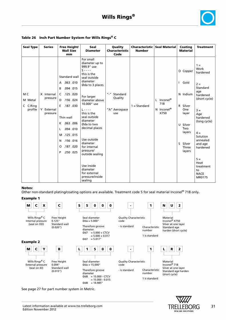
Table 26 Inch Part Number System for Wills Rings® C
Seal Type Series Free Height/ Wall Size
mm
Seal Diameter
Quality Characteristic
Code
Characteristic Number
Seal Material Coating Material
Treatment
M C
M Metal
C C-Ring profile
X Internal pressure
Y External pressure
Standard wall
A .063 .010
B .094 .015
C .125 .020
D .156 .024
E .187 .030
Thin wall
K .063 .006
L .094 .010
M .125 .015
N .156 .016
O .187 .020
P .250 .025
For small diameter up to 999.9" use S - - - - this is the seal outside diameter Øda to 3 places
For larger diameter above 10.000" use
L - - - - this is the seal outside diameter Øda to two decimal places
Use outside diameter for internal pressure/outside sealing
Use inside diameter for external pressure/inside sealing
”-” Standard Quality
”A” Aerospace use
1 = Standard
L Inconel® 718
N Inconel®
X750
O Copper
I Gold
N Indium
R Silver One layer
U Silver Two layers
S Silver Three layers
1 = Work hardened
2 = Standard age hardened (short cycle)
3 = Age hardened (long cycle)
4 = Solution annealed and age hardened
5 = Heat treatment to NACE MR0175
Notes: Other non-standard plating/coating options are available. Treatment code 5 for seal material Inconel® 718 only.
Example 1
M C X C S 5 0 0 0 - 1 N U
Wills Rings® C Internal pressure
(seal on OD)
Free Height 0.125" Standard wall (0.020")
Seal diameter Øda = 5.000"
Therefore groove diameter. Ød7 = 5.000 + CTCV = 5.000 + 0.017 Ød7 = 5.017"
Quality Characteristic code
- is standard Characteristic number
1 is standard
Material Inconel® X750 Silver at one layer Standard age harden (short cycle)
2
Example 2
M C Y B L 1 5 0 0 - 1 L R
Wills Rings® C External pressure
(seal on ID)
Free Height 0.094" Standard wall (0.015")
Seal diameter Øda = 15.000"
Therefore groove diameter Ød8 = 15.000 - CTCV = 15.000 - 0.015 Ød8 = 14.985"
Quality Characteristic code
- is standard Characteristic number
1 is standard
Material Inconel® 718 Silver at one layer Standard age harden (short cycle)
2
See page 27 for part number system in Metric.

32 Latest information available at www.tss.trelleborg.comEdition November 2012
Wills Rings®
� Quality Criteria
The cost-effective use of seals and bearings is highly influenced by the quality criteria set for production. Seals and bearings manufactured by Trelleborg Sealing Solutions are continuously monitored according to strict quality standards from material acquisition through to delivery.
Our quality policy is consistently controlled by strict procedures and guidelines which are implemented within all strategic areas of the company.
Certification of production facilities is in accordance with international standard EN ISO 9000. Facilities meet the specific requirements for quality control and management of purchasing, production and marketing functions.
All testing of materials and products is performed in accordance with accepted test standards and specifications. Inspection specifications correspond to standards applicable to individual product groups. The tenth digit of our part number defines the quality characteristics of the part. A hyphen indicates compliance with standard quality criteria outlined in this catalog.
Customer-specific requirements are indicated by a different symbol in this position. Customers who require special quality criteria should contact their local Trelleborg Sealing Solutions Marketing Company for assistance. We have experience in meeting all types of customer quality requirements.
� Storage
Seals and bearings are often stored as spare parts for prolonged periods. With a few simple precautions, the shelf life of these products can be considerably lengthened.
Seals and bearings should be stored where they are safe from damage by external influences. Deformation, in particular, should be avoided.
The properties of certain materials may change under the influence of various external factors e.g. heat, moisture, light, oxygen, ozone and as a result of contact with liquid media.
The following guidelines should be observed to maintain the optimum physical and chemical properties of the parts:
Heat
The ideal temperature for storage is between +5° C / +41° F and +25° C / +77° F. Direct contact with heaters should be avoided.
Moisture
Parts may be stored dry under normal atmospheric conditions (65 percent rel. moisture ±10).
Weathering
To protect them against damage, seals and bearings should be kept in the original sealed packaging.

33Latest information available at www.tss.trelleborg.comEdition November 2012
Wills Rings®

34 Latest information available at www.tss.trelleborg.comEdition November 2012
Length inch foot yard mm meter
1 inch = 0.0833 0.0278 25.4 0.0254
1 foot = 12 0.333 304.8 0.3048
1 yard = 36 3 914.4 0.9144
1 mm = 0.03937 0.0033 0.00109 0.001
1 meter = 39.37 3.2808 1.0936 1.000
Torque inch-
ounceinch-
poundfoot-
poundkg-
meterNewton-
meter
1 inch-ounce = 0.0625 0.0052 7.2x10⁻⁴ 7.06x10⁻³
1 inch-pound = 16 0.0833 1.152x10⁻² 0.1130
1 foot-pound = 192 12 0.1383 1.356
1 kg-metre = 1,388.7 86.796 7.233 9.80665
1 Newton-meter = 141.6 8.850 0.7375 0.1020
Area inch2 foot2 yard2 mm2 m2
1 inch2 = 0.0069 0.00077 645.16 6.45x10⁻⁴
1 foot2 = 144 0.111 92,903 0.0929
1 yard2 = 1,296 9 836,100 0.8361
1 mm2 = 0.0016 1.0764x10⁻⁵ 1.196x10⁻⁶ 10-6
1 m2 = 1,550 10.764 1.196 106
Volume inch3 US
quartimperial gallon
foot3 US gallon
liter
1 inch Superscript 3 =
0.0173 0.0036 0.00058 0.0043 0.0164
1 US quart = 57.75 0.2082 0.0334 0.25 0.9464
1 imp. gallon = 277 4.8 0.1604 1.2 4.546
1 foot3 = 1,728 29.922 6.23 7.48 28.317
1 US gallon = 231 4 0.8327 0.1337 3.785
1 liter = 61.024 1.0567 0.220 0.0353 0.264
Temperature °K (Kelvin) °C °F
1 °K = °C + 273.15 (°F - 459.67) 5/9
1 °C = °K - 273.15 (°F - 32) 5/9
1 °F = °K 9/5 - 459.67 °C 9/5 + 32
Density ounce/inch3 pound/
foot3g/cm3
1 ounce/inch3 = 108 1.73
1 pound/foot3 = 0.0092 0.016
1 g/cm3 = 0.578 62.43
Force
Newton (N) kilopond (kp)pound force
1 Newton (N) = 0.10197 0.22481
1 kilopond (kp) = 9.80665 2.20463
1 pound force = 4.4482 0.45359
Velocity (Speed)
foot/sfoot/min
mile/hour
meter/skm/hour
1 foot/s = 60 0.6818 0.3048 1.097
1 ft/min = 0.017 0.0114 0.00508 0.01829
1 mile/hour = 1.4667 88 0.447 1.609
1 meter/s = 3.280 196.848 2.237 3.6
1 km/h = 0.9113 54.68 0.6214 0.278
Mass ounce pound kg
1 ounce = 0.0625 0.0283
1 pound = 16 0.4536
1 kg = 35.274 2.2046
Conversion Tables
Pressure inch Hg psi atmosphere torr mm Hg bar MPa kg/cm2
1 inch Hg = 0.491 0.0334 25.4 25.4 0.0339 0.00339 0.0345
1 psi = 2.036 0.0680 51.715 51.715 0.0689 0.00689 0.0703
1 atmosphere = 29.921 14.696 760 760 1.0133 0.10133 1.0332
1 torr = 0.0394 0.0193 0.0013 1 0.0013 0.00013 0.00136
1 mm Hg = 0.0394 0.0193 0.0013 1 0.0013 0.00013 0.00136
1 bar = 29.53 14.504 0.987 749.87 749.87 0.1 1.020
1 MPa = 295.3 145.04 9.869 7498.7 7498.7 10 10.2
1 kg/cm2 = 28.950 14.22 0.968 735.35 735.35 0.980 0.098
SI - Basic UnitsMeasures Units Symbol
Length Meter m
Mass Kilogram kg
Time Second s
Electric current Ampere A
Temperature Kelvin K
Luminous intensity Candela cd
Amount of substance Mol mol
Surface Finish Ra
µm µin
0.1 4
0.2 8
0.4 16
0.8 32
1.6 64
35Latest information available at www.tss.trelleborg.comEdition November 2012
Technical QuestionnaireTechnical Questionnaire
35
Technical Questionnaire
Name: Date:
Division:
Company: Technical proposal:
Type of industry:
- Quotation for pieces
Address:
- p
Annual usage:
Postal / Zip Code:
g
Telephone: Others:
Fax:
Service Conditions and Hardware:
Type of component: Short description of your application orbj iPressure range:
p y ppobjectives:
Operating pressure:
Temperature range:
Operating temperature:
Maximum speed: Operating speed:
Media:
Movement:
oscillating reciprocating
rotational static
Number of cycles/frequencies:
Maximum stroke:
Material (housing/countersurface):
Surface finish:
Service life required:
Latest information available at www.tss.trelleborg.com
Edition 2008June
We would be pleased to send you a technical proposal/quotation for your sealing or bearing application upon receipt of this questionnaire. See the back of this catalog or contacts on www.tss.trelleborg.com for your local Trelleborg Sealing Solutions Marketing Company. Alternatively submit your request for quotation through our website.
Please draw the relevant components here, providing dimensions and machining tolerances, or send a copy ofyour hardware drawing. Also indicate any dimensions that can be changed.

36 Latest information available at www.tss.trelleborg.comEdition November 2012
Complex sealing configurations can feature a large number of sealing elements. Trying to illustrate these on a 2D page is difficult and can never properly show their function or characteristics. Trelleborg Sealing Solutions therefore turned to the latest graphic technologies to produce 3D animations of applications and typical sealing solutions for them.
A range of films specific to different industries or products are available to view on the Trelleborg Sealing Solutions website or via YouTube.
You can now link to our films and animations from
tss.trelleborg.com/films
or view them on You Tube at
YouTube.com/trelleborgseals
Digital Services
You can now link to our films and animations from
tss.trelleborg.com/films
or view them on You Tube at
YouTube.com/trelleborgseals

You can now link to our films and animations from
tss.trelleborg.com/films
37Latest information available at www.tss.trelleborg.comEdition November 2012
Digital Services
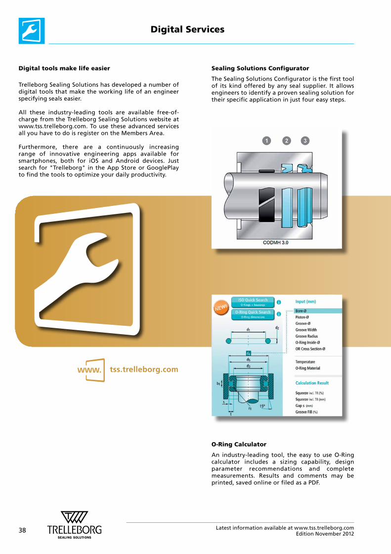
38 Latest information available at www.tss.trelleborg.comEdition November 2012
Digital tools make life easier
Trelleborg Sealing Solutions has developed a number of digital tools that make the working life of an engineer specifying seals easier.
All these industry-leading tools are available free-of-charge from the Trelleborg Sealing Solutions website at www.tss.trelleborg.com. To use these advanced services all you have to do is register on the Members Area.
Furthermore, there are a continuously increasing range of innovative engineering apps available for smartphones, both for iOS and Android devices. Just search for "Trelleborg" in the App Store or GooglePlay to find the tools to optimize your daily productivity.
Sealing Solutions Configurator
The Sealing Solutions Configurator is the first tool of its kind offered by any seal supplier. It allows engineers to identify a proven sealing solution for their specific application in just four easy steps.
O-Ring Calculator
An industry-leading tool, the easy to use O-Ring calculator includes a sizing capability, design parameter recommendations and complete measurements. Results and comments may be printed, saved online or filed as a PDF.
Digital Services
tss.trelleborg.com

39Latest information available at www.tss.trelleborg.comEdition November 2012
Very good suitability+Good suitability
– Limited suitability
+ Unsuitable
? Insufficiant Information
Powerful electronic Catalog
With the powerful electronic catalog you can search through over 100,000 seals by item number or by their properties. Comprehensive and detailed information can be accessed along with an interactive quote facility.
Materials search and chemical compatibility check
These two programs allow you to find out the compatibility of sealing materials with hundreds of different media and help identify the most suitable material for your application.
Versatile CAD service
The CAD download facility provides thousands of drawings from a wide seal range. It gives the option of 2 or 3 dimensional files, in a range of formats to suit most commonly used CAD systems.
Digital Services
Mobile tools and apps
We understand the needs of engineers on the go. Check out our latest mobile tools and apps, ranging from an O-Ring calculator to unit and hardness converters. Just search for "Trelleborg" in the App Store or Google Play to find the tools to optimize your daily productivity.
WWW.TSS.TRELLEBORG.COM
LOCAL CONTACTS
EUROPE
Austria – Vienna (Slovenia) +43 (0) 1 406 47 33 Belgium - Dion-Valmont (Luxembourg)+32 (0) 10 22 57 50 Bulgaria – Sofia (Azerbaijan, Belarus, Greece, Romania, Ukraine)+359 (0) 2 969 95 99 Croatia – Zagreb (Albania, Bosnia and Herzegovina, Macedonia, Serbia, Montenegro)+385 (0) 1 24 56 387 Czech Republic - Rakovnik (Slovakia)+420 313 529 111Denmark – Copenhagen +45 48 22 80 80 Finland – Vantaa (Estonia, Latvia)+358 (0) 207 12 13 50 France - Maisons-Laffitte +33 (0) 1 30 86 56 00
Germany - Stuttgart+49 (0) 711 7864 0 Hungary – Budaörs +36 (06) 23 50 21 21 Italy – Livorno +39 0586 22 6111 The Netherlands - Rotterdam +31 (0) 10 29 22 111 Norway – Oslo+47 22 64 60 80 Poland – Warsaw (Lithuania)+48 (0) 22 863 30 11Russia – Moscow +7 495 627 57 22 Spain – Madrid (Portugal)+34 (0) 91 71057 30Sweden – Jönköping +46 (0) 36 34 15 00
Switzerland – Crissier +41 (0) 21 631 41 11Turkey – Istanbul+90 216 569 73 00 United Kingdom - Solihull (Eire, South Africa)+44 (0) 121 744 1221
Aerospace Hub Europe, North (UK and Nordic Countries) +44 (0) 121 744 1221Aerospace Hub Europe, South & West (Continental Europe and Middle East) +33 (0) 1 30 86 56 00Automotive Hub Europe +49 (0) 711 7864 0
AMERICAS
Americas Regional +1 260 749 9631Brazil – São José dos Campos+55 12 3932 7600Canada Central – Etobicoke, ON+1 416 213 9444Canada East – Montreal, QC+1 514 284 1114Canada West – Langley, BC+1 604 539 0098Mexico - Mexico City+52 55 57 19 50 05
ASIA PACIFIC
Asia Pacific Regional+65 6 577 1778China – Hong Kong+852 2366 9165China – Shanghai+86 (0) 21 6145 1830India – Bangalore+91 (0) 80 3372 9000Japan – Tokyo+81 (0) 3 5633 8008Korea – Seoul+82 (0) 2 761 3471
USA, Great Lakes - Fort Wayne, IN+1 260 482 4050USA, East - Mt. Juliet, TN+1 615 800 8340USA, Midwest - Schaumburg, IL+1 630 539 5500USA, Northern California - Fresno, CA+1 559 449 6070USA, Northwest - Portland, OR+1 503 595 6565USA, Southwest - Houston, TX+1 713 461 3495
Aerospace Hub Airframe+1 303 469 1357Aerospace Hub Distribution & Engineering+1 260 749 9631Aerospace Hub East +1 610 828 3209Aerospace Hub West +1 310 371 1025Automotive Hub North America+1 734 354 1250Automotive Hub South America +55 12 3932 7600
Malaysia - Kuala Lumpur+60 (0) 3 90549266Taiwan – Taichung+886 4 2382 8886Vietnam – Ho Chi Minh City+84 8 6288 6407Singapore and all other countries in South and East Asia, Australasia+65 6 577 1778
Aerospace Hub China +86 (0) 21 6145 1830Aerospace Hub Singapore +65 6 577 1778Automotive Hub China +86 (0) 21 6145 1830Automotive Hub India +91 (0) 80 3372 9200
AFRICA, CENTRAL ASIA AND MIDDLE EAST
Africa & Iran (excluding South Africa (see UK))+41 (0) 21 631 41 11
Central Asia (Armenia, Georgia, Kazakhstan, Kyrgyzstan, Tajikistan, Uzbekistan)+7 495 627 57 22
Middle East and Gulf Region +359 (0) 2 969 95 99

© 2
01
2 T
relle
borg
Gro
up.
At t
ime
of p
ublic
atio
n th
e in
form
atio
n co
ntai
ned
in t
his
liter
atur
e is
bel
ieve
d to
be
corr
ect
and
accu
rate
.99G
BM
OC
ATAE
0812
WWW.TSS.TRELLEBORG.COM
facebook.com/TrelleborgSealingSolutions
twitter.com/TrelleborgSeals
youtube.com/TrelleborgSeals
flickr.com/TrelleborgSealingSolutions
Trelleborg is a world leader in engineered polymer solutions that seal, damp and protect critical applications in demanding environments. Its innovative engineered solutions accelerate performance for customers in a sustainable way. The Trelleborg Group has local presence in over 40 countries around the world.