william stallings data and computer...
TRANSCRIPT
1
William Stallings
Data and Computer
Communications
Chapter 8
Multiplexing

Dr. Mohammed Arafah William Stallings “Data and Computer Communications” 2
Multiplexing
multiple channels on 1 physical line
common on long-haul, high capacity, links
have FDM, TDM, STDM alternatives

Dr. Mohammed Arafah William Stallings “Data and Computer Communications” 3
Frequency Division Multiplexing
Possible with large bandwidth
Multiple signals carried simultaneously
Each signal modulated onto different carrier frequency
Carrier frequencies must be sufficiently separated
Bandwidths should not overlap

Dr. Mohammed Arafah William Stallings “Data and Computer Communications” 4
Frequency Division Multiplexing

Dr. Mohammed Arafah William Stallings “Data and Computer Communications” 5
Frequency Division Multiplexing
MUX
Signal 2
Signal 3
Signal 1
Signal n
DMUX
Signal n
Signal 2
Signal 3
Signal 1Channel 1 (Frequency 1)
Channel 2 (Frequency 2)
Channel 3 (Frequency 3)
Channel n (Frequency N)
Time
Freq
uen
cy

Dr. Mohammed Arafah William Stallings “Data and Computer Communications” 6
Channel
Frequency Modulator
(Carrier 2)
Frequency Modulator
(Carrier 1)Signal 1
Frequency Modulator
(Carrier n)
Signal 2
Signal n
Transmitter
Frequency Demodulator
(Carrier 2)
Frequency Demodulator
(Carrier 1)Signal 1
Frequency Demodulator
(Carrier n)
Signal 2
Signal n
Receiver
Frequency Division Multiplexing

Dr. Mohammed Arafah William Stallings “Data and Computer Communications” 7
Frequency Division Multiplexing

Dr. Mohammed Arafah William Stallings “Data and Computer Communications” 8
Frequency Division Multiplexing

Dr. Mohammed Arafah William Stallings “Data and Computer Communications” 9
Bandwidth of voice signal (300-3400 Hz)
Generally taken as 4 kHz
Using AM with carrier frequency 64 kHz
Spectrum of modulated signal is 8 kHz
60 kHz – 68 kHz
To make efficient use of bandwidth
transmit only lower sideband
Frequency Division Multiplexing:
Voice Signal

Dr. Mohammed Arafah William Stallings “Data and Computer Communications” 10
Frequency Division Multiplexing:
Voice Signal

Dr. Mohammed Arafah William Stallings “Data and Computer Communications” 11
Frequency Division Multiplexing
B = total channel bandwidth where
Bi = bandwidth of a signal
n
i
iBB1
Signal 2(Lower Band)
Signal n(Lower Band)
Signal 1(Lower Band)
Total Channel Bandwidth (B)
Power
Frequency
B1 B2Bn
Subcarrier
f1
Subcarrier
f2
Subcarrier
fn

Dr. Mohammed Arafah William Stallings “Data and Computer Communications” 12
FDM Problems
Crosstalk
spectra of adjacent component signals overlap
guard band should be added
e.g. voice 4 kHz instead of 3400 Hz
Intermodulation noise
nonlinear effects of amplifiers on a signal in one channel could produce frequency components of other channels

Dr. Mohammed Arafah William Stallings “Data and Computer Communications” 13
Analog Carrier Systems
long-distance links use an FDM hierarchy
AT&T (USA) and ITU-T (International) variants
Group12 voice channels (4kHz each) = 48kHz
in range 60kHz to 108kHz
SupergroupFDM of 5 group signals supports 60 channels
on carriers between 420kHz and 612 kHz
MastergroupFDM of 10 supergroups supports 600 channels
so original signal can be modulated many times

Dr. Mohammed Arafah William Stallings “Data and Computer Communications” 14
North America and International carrier standards:
CCITAT&TSpectrumBandwidthNumber of
Voice Channels
GroupGroup60-108 KHz48 KHz12
SupergroupSupergroup312-552 KHz240 KHz60
Mastergroup812-2044 KHz1.232 MHz300
Mastergroup564-3084 KHz2.52 MHz600
Supermaster Group8.516-12.388 MHz3.872 MHz900
Mastergroup MultiplexN × 600
Jumpogroup0.564-17.548 MHz16.984 MHz3,600
Jumpogroup Multiplex3.124-60.566 MHz57.442 MHz10,800
Frequency Division Multiplexing

Dr. Mohammed Arafah William Stallings “Data and Computer Communications” 15
Frequency Division Multiplexing

Dr. Mohammed Arafah William Stallings “Data and Computer Communications” 16
Frequency Division Multiplexing

Dr. Mohammed Arafah William Stallings “Data and Computer Communications” 17
Wavelength Division Multiplexing
FDM with multiple beams of light at different frequencies are transmitted on the same optical fibercommercial systems with 160 channels of 10 Gbps
Alcatel has carried 256 channels at 39.8 Gbps each, a total of 10.1 Tbps, over a 100-km
architecture similar to other FDM systemsmultiplexer consolidates laser sources (1550nm) for transmission
over single fiber
optical amplifiers amplify all wavelengths
demultiplexer separates channels at the destination
1
2
n
1
2
n
Optical Fiber
Multiplexer Demultiplexer
i: wavelengthi

Dr. Mohammed Arafah William Stallings “Data and Computer Communications” 18
Dense Wavelength Division Multiplexing
Dense wavelength division multiplexing (DWDM) refers originally to optical signals multiplexed within the 1550 nm band so as to utilize the capabilities of optical amplifiers which are effective for wavelengths between approximately 1525-1565 nm (C band), or 1570-1610 nm (L band)
DWDM combines up to several wavelengths onto a single fiber and uses an ITU standard that specifies 100GHz or 200GHz spacing between the wavelengths, arranged in several bands around 1500-1600nm.
use of more channels, more closely spaced, than ordinary FDM, resulting in the multiplexing equipment being more complex and expensive

Dr. Mohammed Arafah William Stallings “Data and Computer Communications” 19
Dense Wavelength Division Multiplexing
channel spacing of 200GHz or less could be considered dense
typical system would use 40 channels at 100 GHz spacing or 80 channels with 50 GHz spacing
Some technologies are capable of 25 GHz spacing (sometimes called ultra dense WDM)
40 channels DWDM

Dr. Mohammed Arafah William Stallings “Data and Computer Communications” 20
Dense Wavelength Division Multiplexing
Connecting locations redundantly with a Multiple-10Gbit/s Fiber Optic Ring

Dr. Mohammed Arafah William Stallings “Data and Computer Communications” 21
multiple digital signals carried on single path
portions of each signal interleaved in time
byte Interleaving, each time slot contains one character of data
time slots pre-assigned to sources
Synchronous TDM is called synchronous not because synchronous transmission is used, but because the time slots are pre-assigned to sources and fixed.
slot transmitted even if source has no data
may waste capacity but simple to implement
different data rates are possible
fast source can be assigned multiple slots
slots dedicated to source called channel
Synchronous Time Division Multiplexing

Dr. Mohammed Arafah William Stallings “Data and Computer Communications” 22
At the transmitter:
data from each source is buffered
buffers scanned sequentially to form a composite digital signal mc(t)
scanning operation is sufficiently rapid so that each buffer is emptied before more data can arrive
The data rate of the composite signal mc(t) must be at least equal the sum of data rates of input signals mi(t)
data organized into frames, each frame contains a cycle of time slots
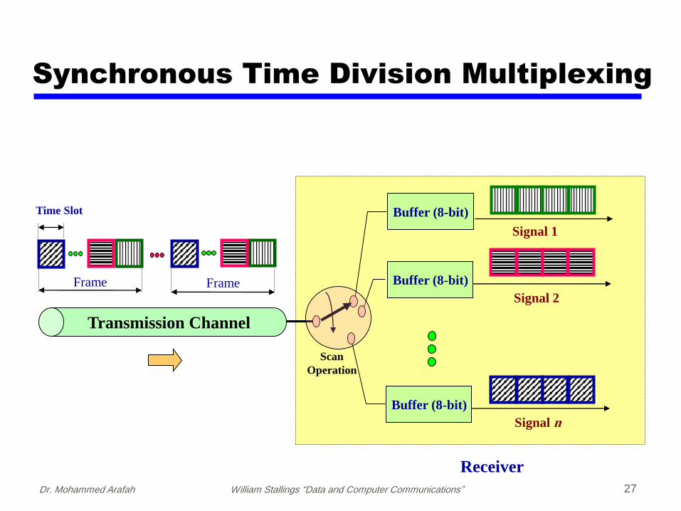
At the receiver:
the interleaved data are demultiplexed and routed to the appropriate destination buffer.
Synchronous Time Division Multiplexing

Dr. Mohammed Arafah William Stallings “Data and Computer Communications” 23
Synchronous Time Division Multiplexing

Dr. Mohammed Arafah William Stallings “Data and Computer Communications” 24
Frame
Tim
e S
lot
3 (
Sig
na
l 3
)
Tim
e S
lot
2 (
Sig
na
l 2
)
Tim
e S
lot
1 (
Sig
na
l 1
)
Tim
e S
lot
n(S
ign
al
n)
Frame
Tim
e S
lot
3 (
Sig
na
l 3
)
Tim
e S
lot
2 (
Sig
na
l 2
)
Tim
e S
lot
1 (
Sig
na
l 1
)
Tim
e S
lot
n(S
ign
al
n)
Time Slot
MUX
Signal 2
Signal 3
Signal 1
Signal n Signal n
Signal 2
Signal 3
Signal 1
DMUX
Time
Freq
uen
cy
Synchronous Time Division Multiplexing

Dr. Mohammed Arafah William Stallings “Data and Computer Communications” 25
Frame 3
D C B A
Frame 2
D C B A
Frame 1
Time Slot
D C B A
Frame x
D C B A
Transmission Channel
Synchronous Time Division Multiplexing
1 link, 4 channelsMUX
4 Inputs
DMUX
4 Outputs
Transmitters Receivers
C
A
B
D

Dr. Mohammed Arafah William Stallings “Data and Computer Communications” 26
Frame
Time Slot
Frame
Synchronous Time Division Multiplexing
Buffer (8-bit)
Signal 1
Transmitters
Sampling Clock
Buffer (8-bit)
Buffer (8-bit)
Signal 2
Signal n
قناة اإلرسال
Scan
Operation
Dr. Mohammed Arafah William Stallings “Data and Computer Communications” 27
Transmission Channel
Frame
Time Slot
Frame
Synchronous Time Division Multiplexing
Receiver
Signal 1
Signal 2
Signal n
Buffer (8-bit)
Buffer (8-bit)
Buffer (8-bit)
Scan
Operation

Dr. Mohammed Arafah William Stallings “Data and Computer Communications” 28
Frame1
Time Slot
D C B A
Transmission Channel
Frame 2
D C
Empty
Frame 3
C B
EmptyEmpty
Frame x
D A
Empty
Synchronous Time Division Multiplexing
1 link, 4 channelsMUX
4 Inputs
DMUX
4 Outputs
Transmitters Receivers
C
A
B
D
Bursty traffic Waste of resources

Dr. Mohammed Arafah William Stallings “Data and Computer Communications” 29
Synchronous Time Division Multiplexing
Rate of mc(t) must be ≥ Σni mi(t)

Dr. Mohammed Arafah William Stallings “Data and Computer Communications” 30
Time Division Multiplexing

Dr. Mohammed Arafah William Stallings “Data and Computer Communications” 31
TDM Link Control
no headers and trailers
data link control protocols (flow control and error control) not needed
flow controlAs far as multiplexers and demultiplexers are concerned, flow
control is not needed.
data rate of multiplexed line is fixed
if one channel is temporarily unable to accept data, the other channels are expecting to receive data at predetermined time
corresponding source must be quenched
the channel will carry empty slots
flow control can be provided on per channel basis
error controlerror control can be provided on per channel basis by using HDLC

Dr. Mohammed Arafah William Stallings “Data and Computer Communications” 32
Data Link Control on TDM

Dr. Mohammed Arafah William Stallings “Data and Computer Communications” 33
Framing
It is important to maintain framing synchronization because, if the source and destination are out of step, data on all channels are lost
added digit framing:
one control bit added to each TDM frame T1 Link
identifiable bit pattern used on control channele.g., alternating 01010101…unlikely on a data channel
E1 Link

Dr. Mohammed Arafah William Stallings “Data and Computer Communications” 34
Synchronizing Multiple Sources
Pulse Stuffing
Most difficult problem in TDM design
If each source has separate clock
any variation among clocks loss of sync
Input data rates not related by simple rational number
Pulse stuffing is a common solution
have outgoing data rate (excluding framing bits) higher than sum of incoming rates
stuff extra dummy bits or pulses into each incoming signal until it matches local clock
stuffed pulses inserted at fixed locations in frame and removed at demultiplexer

Dr. Mohammed Arafah William Stallings “Data and Computer Communications” 35
Pulse Stuffing - Example
Inputs:
Source 1: Analog, 2 kHz
Source 2: Analog, 4 kHz
Source 3: Analog, 2 kHz
Sources 4-11: Digital, 7200 bps

Dr. Mohammed Arafah William Stallings “Data and Computer Communications” 36
Pulse Stuffing - Example
For analog sources:Sources 1, 3 sampled at 4000 samples/secSource 2 at 8000 samples/secPAM samples are then quantized using 4 bits/sample PCM
At scan rate of 4000 times per second , one PAM sample (4 bits) is taken from sources 1, 3 and two PAM samples (8 bits) are taken from source 2 per scan
These four samples are interleaved and converted to 4-bit PCM samples
Total of 16 bits are generated at rate of 4000 times per second 64 kbps
For digital sources:Pulse stuffing raise each source to a rate of 8 kbpsaggregate data rate = 64 kbps
For example, frame can consist of 32 bits Each frame containing 16 PCM bits (64kbps/128kps*32) and 2 bits
(8kbps/128kbps*32) from each of the eight digital sources.

Dr. Mohammed Arafah William Stallings “Data and Computer Communications” 37
Pulse Stuffing - Example4 ksamples/sec
8 ksamples/sec
4 ksamples/sec
64 kbps64 kbps
16 ksamples/sec
8 kbps800 bps

Dr. Mohammed Arafah William Stallings “Data and Computer Communications” 38
Pulse Stuffing - Example4 ksamples/sec
8 ksamples/sec
4 ksamples/sec
16 ksamples/sec
32-bit Frame
64 kbps 16 bits
64 kbps
16 bits

Dr. Mohammed Arafah William Stallings “Data and Computer Communications” 39
Digital Carrier Systems
Synchronous TDM transmission structure
TDM performed at multiple levels
Hierarchy of TDM structures
US, Canada, Japan use AT&T system
Other countries use ITU-T system

Dr. Mohammed Arafah William Stallings “Data and Computer Communications” 40
long-distance links use an TDM hierarchy
AT&T (USA) and ITU-T (International) variants
The basis of the TDM hierarchy used in North America and Japan is the Digital signal-1 (DS-1), also known as T1
DS-1 can carry mixed voice and data signals
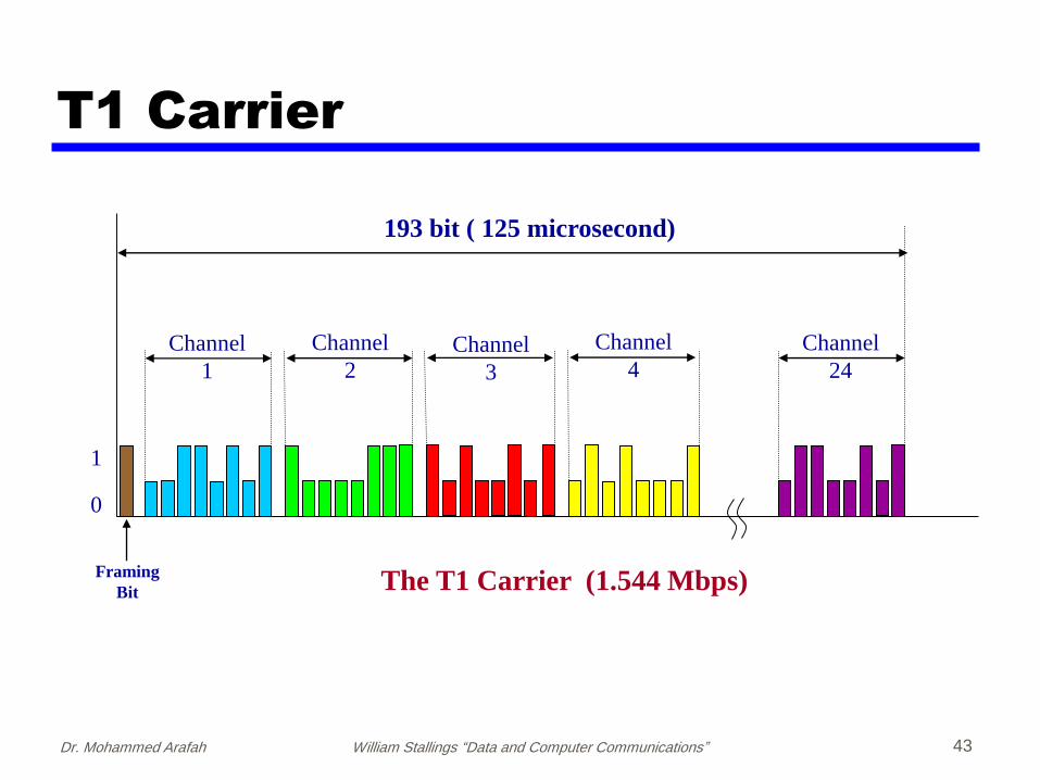
DS-1 frame consists of 24 × 8 = 192 data bits, plus one extra bitfor framing, yielding 193 bits every 125 msec
aggregate data rate of 8000 × 193 = 1.544 Mbps
frame synchronization in DS-1 link uses an extra bit at the start ofeach frame which alternates between 1 and 0 for consecutiveframes.
higher-level multiplexing is achieved by interleaving DS-1 inputsDS-2 is four DS-1 at 6.312Mbps
T1 Carrier

Dr. Mohammed Arafah William Stallings “Data and Computer Communications” 41
T1 Carrier

Dr. Mohammed Arafah William Stallings “Data and Computer Communications” 42
1 DS-1 Frame (125 sec) = 24 Time Slot + 1 Framing Bit
23 24 1 2 3 4 5 6 7 8 9 10 11 12 13 14 15 16 17 18 19 20 21 22 23 24 1 2
Framing Bit
… …
Aggregate data rate of 1.544 Mbps
Time Slot
8 bits
T1 Carrier
Dr. Mohammed Arafah William Stallings “Data and Computer Communications” 43
Channel
1
Channel
2Channel
3
Channel
4
Framing
Bit
1
0
Channel
24
The T1 Carrier (1.544 Mbps)
193 bit ( 125 microsecond)
T1 Carrier

Dr. Mohammed Arafah William Stallings “Data and Computer Communications” 44
Digital Bit Stream
Buffer (8-bit)Signal 1
Signal 2
Signal
24
Buffer (8-bit)
Buffer (8-bit)
Sampling Clock
Analog Voice
Input Circuits
Scan
Operation
T1 Carrier

Dr. Mohammed Arafah William Stallings “Data and Computer Communications” 45
ANSI PDH Transmission Hierarchies

Dr. Mohammed Arafah William Stallings “Data and Computer Communications” 46
1
4
3
2
7
6
5
T3
44.736 Mbps
123412
T2
6.312 Mbps
44
T1
T1
T1
1
4
3
2
33
22
T1
11
1.544 Mbps
139.264 Mbps
1
3
2
T4
ANSI PDH Transmission Hierarchies

Dr. Mohammed Arafah William Stallings “Data and Computer Communications” 47
E1 Carrier
ITU-T recommends for a PCM carrier at 2.048 Mbpscalled E1 Carrier.
This carrier has 32 of 8-bit data samples, yielding 256bits every 125 sec.
This gives the gross data rate of 2.048 Mbps.
Thirty of the channels are used for information and twoare used for signaling.
Outside North America and Japan, the E1 carrier iswidely used.

Dr. Mohammed Arafah William Stallings “Data and Computer Communications” 48
1 E1 Frame = 125 sec = 32 Time Slot = 2.048 Mbps
0 1 2 3 4 5 6 7 8 9 10 11 12 13 14 15 16 17 18 19 20 21 22 23 24 25 26…
27 28 29 30 31
Frame
SynchronizationSignaling
Control
E1 Carrier

Dr. Mohammed Arafah William Stallings “Data and Computer Communications” 49
ITU-T PDH Transmission Hierarchies

Dr. Mohammed Arafah William Stallings “Data and Computer Communications” 50
ITU-T PDH Transmission Hierarchies

Dr. Mohammed Arafah William Stallings “Data and Computer Communications” 51
ITU-T PDH Transmission Hierarchies

Dr. Mohammed Arafah William Stallings “Data and Computer Communications” 52
SONET/SDH
SONET (Synchronous Optical Network)
optical transmission interface
proposed by BellCore, standardize by ANSI
SDH (Synchronous Digital Hierarchy)
compatible version published by ITU-T
few differences from SONET

Dr. Mohammed Arafah William Stallings “Data and Computer Communications” 53
Synchronous Optical Network (SONET) is a digital transportsystem.
In SONET, the base transfer rate is 51.84 Mbps, a 125 secsignal, and a frame format of 9 rows by 90 columns (90columns * 9 rows * 8 bit/byte * 8000 = 51.84 Mbps.
The basic rate of SONET, known as SynchronousTransport Signal 1 (STS-1), is 51.84 Mbps.
SONET is the standard in North America, which ispermitted to be multiplexed by an integer of three to theEuropean preference of 155.520 Mbps.
Synchronous Optical Network (SONET)

Dr. Mohammed Arafah William Stallings “Data and Computer Communications” 54
Payload
1
2
3
4
5
6
7
8
9
Section
Overhead
Line
Overhead
P
A
T
H
O
V
E
R
H
E
A
D
87 Octets3 Octets
90 Octets9 Rows
STS-1 Envelope
STS-1 Frame

Dr. Mohammed Arafah William Stallings “Data and Computer Communications” 55
Fiber Channel
Flag… Flag Flag
STS-1 Frame
STS-1 Envelope
Flag

Dr. Mohammed Arafah William Stallings “Data and Computer Communications” 56
Destination
MultiplexerMultiplexer
Section Section Section Section
Line Line
Path
Path
Header
Line
Header
Section
Header
Section
Header
Source
Multiplexer
Line
Header
Section
Header
Section
Header
SONET Overheads

Dr. Mohammed Arafah William Stallings “Data and Computer Communications” 57
SONET Overheads

Dr. Mohammed Arafah William Stallings “Data and Computer Communications” 58
SONET Overheads

Dr. Mohammed Arafah William Stallings “Data and Computer Communications” 59
SONET - Section Overhead

Dr. Mohammed Arafah William Stallings “Data and Computer Communications” 60
SONET - Line Overhead

Dr. Mohammed Arafah William Stallings “Data and Computer Communications” 61
SONET - Path Overhead

Dr. Mohammed Arafah William Stallings “Data and Computer Communications” 62
In SDH, the base transfer rate is 155.52 Mbps, a 125 secsignal, and a frame format of 9 rows by 270 columns (270columns * 9 rows * 8 bit/byte * 8000 = 155520000 bps.
The basic rate of SDH, known as SynchronousTransport Module 1 (STM-1), is 155.52 Mbps.
SDH is a European Standard and was developed by ITU-T.
Synchronous Digital Hierarchy (SDH)

Dr. Mohammed Arafah William Stallings “Data and Computer Communications” 63
Payload
1
2
3
4
5
6
7
8
9
Overhead
261 Octets9 Octets
270 Octets9 Rows
SDH Envelope
Synchronous Digital Hierarchy (SDH)

Dr. Mohammed Arafah William Stallings “Data and Computer Communications” 64
SONET/SDH Multiplexing

Dr. Mohammed Arafah William Stallings “Data and Computer Communications” 65
SONET/SDH Multiplexing

Dr. Mohammed Arafah William Stallings “Data and Computer Communications” 66
SONET/SDH Multiplexing
Dr. Mohammed Arafah William Stallings “Data and Computer Communications” 67
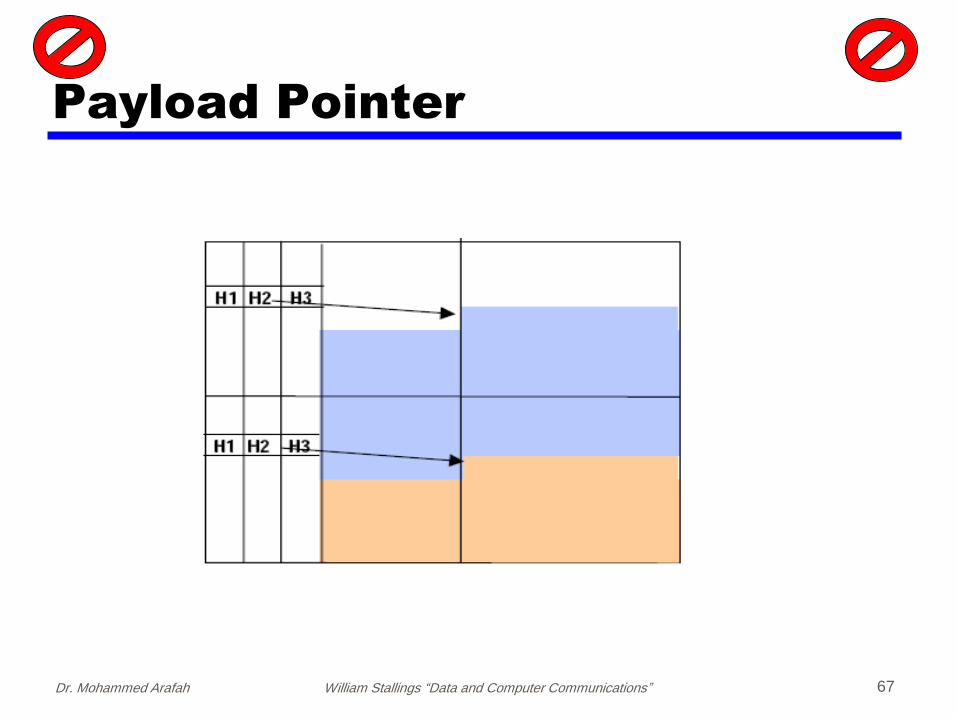
Payload Pointer

Dr. Mohammed Arafah William Stallings “Data and Computer Communications” 68
Payload Pointer

Dr. Mohammed Arafah William Stallings “Data and Computer Communications” 69
STS-1 Frame 9 bytes
87 bytes
J1
B3
C2
G1
F2
H4
Z3
Z4
Z5
VT
1.5
# 1
VT
1.5
# 2
VT
1.5
# 3
…
VT
1.5
# 28
R
R
R
R
R
R
R
R
R
VT
1.5
# 1
VT
1.5
# 2
VT
1.5
# 3
…
VT
1.5
# 28
R
R
R
R
R
R
R
R
R
VT
1.5
# 1
VT
1.5
# 2
VT
1.5
# 2
…
VT
1.5
# 28
1 2 ………. 29 30 31 ……… 58 59 60 ………
87
Fixed Stuff byteSTS-1 Path
Overhead
STS-1 SPE for all VT1.5 (T1 Container)
Dr. Mohammed Arafah William Stallings “Data and Computer Communications” 70
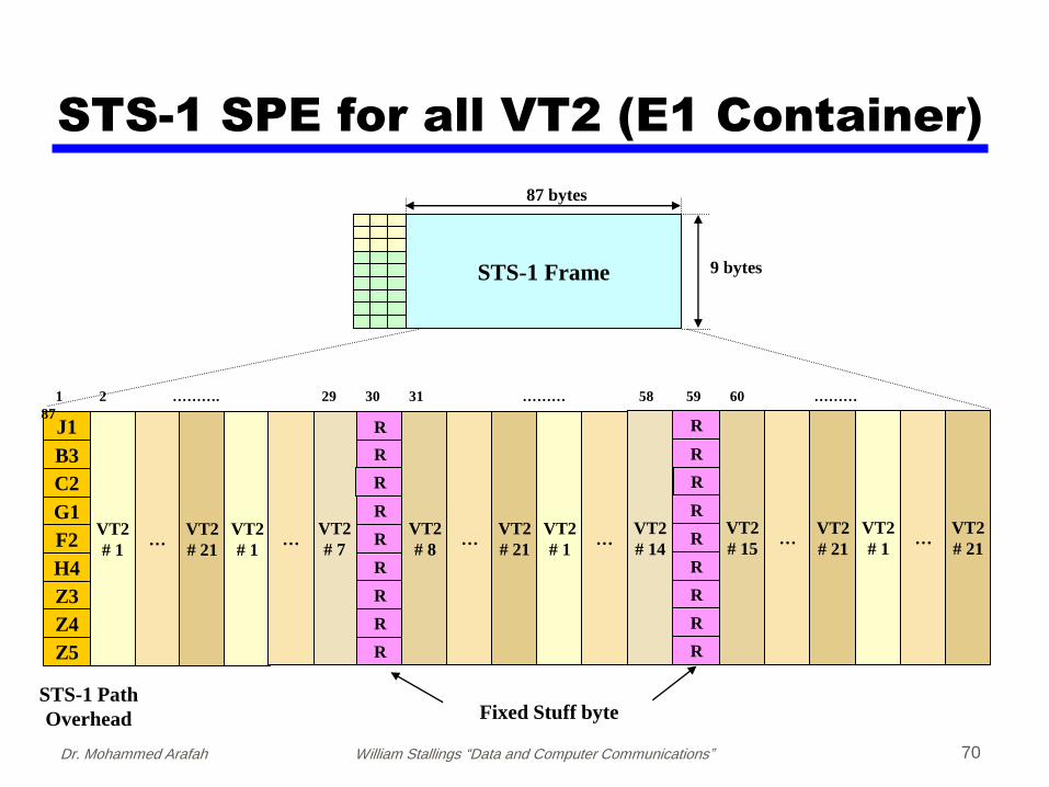
STS-1 Frame 9 bytes
87 bytes
STS-1 Path
Overhead
J1
B3
C2
G1
F2
H4
Z3
Z4
Z5
VT2
# 1…
VT2
# 21
VT2
# 1
VT2
# 7
R
R
R
R
R
R
R
R
R
VT2
# 8…
VT2
# 21
VT2
# 1…
R
R
R
R
R
R
R
R
R
VT2
# 15…
VT2
# 1…
VT2
# 21
1 2 ………. 29 30 31 ……… 58 59 60 ………
87
Fixed Stuff byte
…VT2
# 14
VT2
# 21
STS-1 SPE for all VT2 (E1 Container)

Dr. Mohammed Arafah William Stallings “Data and Computer Communications” 71
SONET/SDH
STS-1 28 T1 Links
21 E1 Links
STS-N N*28 T1 Links
N*21 E1 Links
STM-1 3 STS-1
3*28 T1 Links
3*21 E1 Links
STM-N N*3 STS-1
N*3*28 T1 Links
N*3*21 E1 Links

Dr. Mohammed Arafah William Stallings “Data and Computer Communications” 72
SONET/SDH
Synchronous Optical Network (ANSI)
Synchronous Digital Hierarchy (ITU-T)
have hierarchy of signal rates
Synchronous Transport Signal level 1 (STS-1) or Optical Carrier level 1 (OC-1) is 51.84Mbps
carries one DS-3 or multiple (DS1 DS1C DS2) plus ITU-T rates (eg. 2.048Mbps)
multiple STS-1 combine into STS-N signal
ITU-T lowest rate is 155.52Mbps (STM-1)

Dr. Mohammed Arafah William Stallings “Data and Computer Communications” 73
DS-0
Equiv. #
DS-1
Equiv. #
DS-3
Equiv. #
Transmission rate (Mbps)
SDH
Optical
SONET
OpticalElectrical
67228151.840OC-1STS-1
2016843155.520STM-1OC-3STS-3
60482529466.560STM-3OC-9STS-9
806433612622.080STM-4OC-12STS-12
1209650418933.120STM-6OC-18STS-18
16128672241244.160STM-8OC-24STS-24
241921008361866.240STM-12OC-36STS-36
322561344482488.320STM-16OC-48STS-48
12902453761929953.280STM-64OC-192STS-192
SONET/SDH

Dr. Mohammed Arafah William Stallings “Data and Computer Communications” 74
Statistical TDM
in Synchronous TDM many slots are wasted
Statistical TDM allocates time slots dynamically based on demand
multiplexer scans input lines and collects data until frame full
There are n I/O lines and k time slots available on the TDM frame, where k < n
line data rate lower than aggregate input line rates
may have problems during peak periods
must buffer inputs

Dr. Mohammed Arafah William Stallings “Data and Computer Communications” 75
Statistical TDM
Output data rate is less than the sum input rates
Can take more sources than synchronous TDM at same output rate or less output rate for same sources as synchronous TDM
Statistical Multiplexer does not send empty slots if there are data to send
More overhead than TDM
slot positions must be identified address information must
be included with data

Dr. Mohammed Arafah William Stallings “Data and Computer Communications” 76
Statistical TDM

Dr. Mohammed Arafah William Stallings “Data and Computer Communications” 77
Frame Structure
Control information is needed
Two possible formats:
One data source per frame
need to identify address of source
work well under light load
inefficient under heavy load
Multiple sources per frame
need to identify length of data of each source

Dr. Mohammed Arafah William Stallings “Data and Computer Communications” 78
Statistical TDM Frame Format

Dr. Mohammed Arafah William Stallings “Data and Computer Communications” 79
Statistical TDM - Performance
Parameters for statistical TDM:
I = number of Input sources
R = data rate of each source, bps
= effective capacity of multiplexed line, bps
= mean fraction of time each source is transmitting, 0<<1
= ratio of multiplexed line capacity to total maximum input
If K=0.25 four times as many devices using the same link capacity
K can be bounded: <K <1
If K = 1 Synchronous TDM
if K < , then a single input will exceed the multiplexer capacity
IRK

Dr. Mohammed Arafah William Stallings “Data and Computer Communications” 80
Statistical TDM - Performance

Dr. Mohammed Arafah William Stallings “Data and Computer Communications” 81
Statistical TDM - Performance
Viewing the multiplexer as a single-server queue, and assuming Poisson arrivals and constant service time
Parameters:
= arrival rate (mean number of arrivals per second)
= mean service rate
Ts = service time for each arrival
= utilization, fraction of time server is busy
Nw = mean number of waiting items in the system
N = mean number of items in the system (waiting + being served)
Tr = residence time, mean time an item spends in the system (waiting + being served)
r = standard deviation of Tr
1sT
wNN

Dr. Mohammed Arafah William Stallings “Data and Computer Communications” 82
Statistical TDM - Performance Formulas:
IR
1sT
sT
)1(2
2
N
)1(2
)2()
)1(2
2()
)1(2
22()
)1(2(
/
2222
ssss
s
r
TTTT
T
NNT
126
5
2
3
)1(
1 432
r
)1(2
2
wN
Little's Law tells us that the average number of customers in the system N, is the effective arrival rate λ, times the average
time that a customer spends in the system Tr, or simply:
NTTN rr
= Utilization, fraction of time server is busy
Ts = service time for each arrival
= Mean number of arrivals per second
N = mean number of items in the system
Nw = mean number of waiting items in the system
N = mean number of items in the system
Tr = Mean time an item spends in the system
r = standard deviation of Tr
K
IR

Dr. Mohammed Arafah William Stallings “Data and Computer Communications” 83
Statistical TDM - Performance
Line utilization
Bu
ffer
siz
e (f
ram
es)
Mean buffer size versus utilization
)1(2
2
wN
Line utilization
Del
ay (
ms)
Mean delay versus utilization
=25 Kbps =50 Kbps
=100 Kbps
)1(2
)2(
s
r
TT
1sT

Dr. Mohammed Arafah William Stallings “Data and Computer Communications” 84
Statistical TDM - Performance
Buffer size
Pro
bab
ilit
y o
f over
flow
Probability of overflow as a function of buffer size

Dr. Mohammed Arafah William Stallings “Data and Computer Communications” 85
Cable Modems
dedicate two cable TV channels to data transfer
each channel shared by number of subscribers, using statistical TDM
Downstreamcable scheduler delivers data in small packets
active subscribers share downstream capacity
grant requests to allocate upstream time slots to subscribers
Upstreamuser requests timeslots on shared upstream channel
Headend scheduler notifies subscriber of slots to use

Dr. Mohammed Arafah William Stallings “Data and Computer Communications” 86
Upstream
Downstream
…
Cable Modem Scheme
…

Asymmetrical Digital Subscriber
Line (ADSL)
Telephone Network
DSL Modem Router
Home Phone Internet
DS
LA
M
Splitter
Central Office
Home PC
Phone Line
Router
Mobilehosts
87Dr. Mohammed Arafah
Dr. Mohammed Arafah William Stallings “Data and Computer Communications” 88
Asymmetrical Digital Subscriber
Line (ADSL)
Customers Premises
DSL Router Modem

Dr. Mohammed Arafah William Stallings “Data and Computer Communications” 89
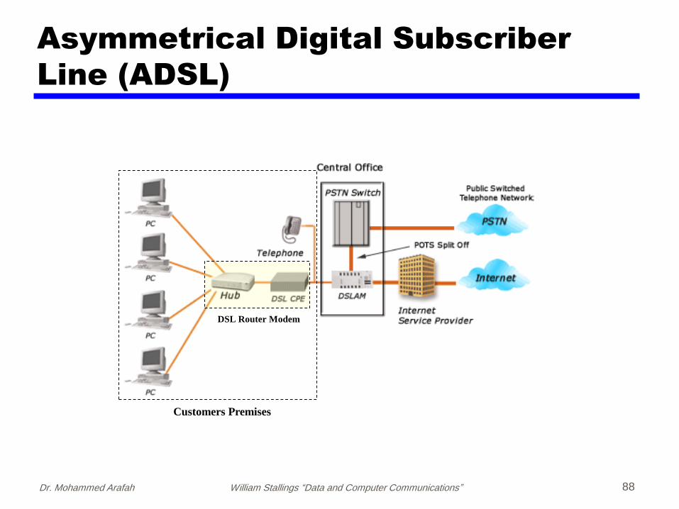
Asymmetrical Digital Subscriber
Line (ADSL)
subscriber line: link between subscriber and network
carry voice grade signal: 0 – 4 kHz
uses currently installed twisted pair cablesupport 1 MHz or more
Provide high speed data over phone line
Asymmetric DSL (ADSL)more downstream rate than upstream
most home user traffic is downstream
uses Frequency division multiplexingreserve lowest 25kHz for voice (POTS)
more than 4 kHz to prevent interference
has a range of up to 5.5km

Dr. Mohammed Arafah William Stallings “Data and Computer Communications” 90
Asymmetrical Digital Subscriber
Line (ADSL)
Frequency plan for ADSL. Red area is the frequency range used by
normal voice telephony (PSTN), the green (upstream) and blue
(downstream) areas are used for ADSL

Dr. Mohammed Arafah William Stallings “Data and Computer Communications” 91
Discrete Multitone (DMT)
DMT separates the ADSL signal into 256 subchannels (bins)
Transmission band divided to 4.3125 kHz subchannels
Each subchannel can carry a data rate up to 60 kbps
DMT has 224 downstream frequency bins and up to 26upstream bins.
The frequency layout can be summarized as: 30Hz-4 kHz, voice. 4-25 kHz, unused guard band. 25-138 kHz, 26 upstream bins (7-32). 138-1104 kHz, 224 downstream bins (33-256).
Typically, a few bins around 32-33 are not used in order to prevent interference between upstream and downstream bins either side of 138 kHz.
http://en.wikipedia.org/wiki/ITU_G.992.1
Dr. Mohammed Arafah William Stallings “Data and Computer Communications” 92
Discrete Multitone (DMT)
DMT modem sends out test signals on each subchannel to determine signal-to-noise ratio
DMT modem then assigns more bits to channels with better signal transmission qualities and less bits to channels with poorer signal transmission qualities
typical situation in which there is increasing attenuation and hence decreasing signal-to-noise ratio at higher frequencies
As the higher-frequency subchannels carry less of the load

Dr. Mohammed Arafah William Stallings “Data and Computer Communications” 93
Discrete Multitone (DMT)

Dr. Mohammed Arafah William Stallings “Data and Computer Communications” 94
Discrete Multitone (DMT)
Bit stream to be transmitted is divided into a number of parallel bit streams (substreams)
Each substream is carried in separate frequency band using FDM
Sum of the data rates of the substreams is equal to the total data rate
Each substream is then converted to an analog signal using QAM
This scheme works easily because of QAM’s ability to assign different numbers of bits per transmitted signal
Each QAM signal occupies a distinct frequency band, so these signals can be combined by simple addition to produce the composite signal for transmission

Dr. Mohammed Arafah William Stallings “Data and Computer Communications” 95
DMT Transmitter

Dr. Mohammed Arafah William Stallings “Data and Computer Communications” 96
ADSL Standards

Dr. Mohammed Arafah William Stallings “Data and Computer Communications” 97
Saudi Arabia
STC offers ADSL2+ service at maximum of 20 Mbit/s downstream data rate. The service is called Xband Jood and as of 2010 costs SAR 296 per month.
The maximum attainable data rate however depends on the location and is usually less than stated maximum of 20 Mbit/s at most locations.
http://en.wikipedia.org/wiki/ITU_G.992.5

Dr. Mohammed Arafah William Stallings “Data and Computer Communications” 98
ADSL2+
ADSL2+ extends the capability of basic ADSL by doubling the number of downstream bits. The data rates can be as high as 24 Mbps downstream andup to 1.4 Mbps upstream depending on the distance from the DSLAM to the customer's premises.
ADSL2+ is capable of doubling the frequency band of typical ADSL connections from 1.1 MHz to 2.2 MHz. This doubles the downstream data rates of the previous ADSL2 standard (which was up to 12 Mbit/s), but like the previous standards will degrade from its peak bit rate after a certain distance.

Dr. Mohammed Arafah William Stallings “Data and Computer Communications” 99
ADSL2
http://www.billion.com/edu/AnnexM_Whitepaper.pdf

Dr. Mohammed Arafah William Stallings “Data and Computer Communications” 100
xDSL
High data rate DSL (HDSL)two-binary, one-quaternary (2B1Q)
coding on dual twisted pairs
up to 2Mbps over 3.7km
Single line DSL2B1Q coding on single twisted pair (residential) with
echo cancelling
up to 2Mbps over 3.7km
Very high data rate DSLDMT/QAM for very high data rates
over separate bands for separate services

Dr. Mohammed Arafah William Stallings “Data and Computer Communications” 101
xDSL
ADSL = Asymmetric DSLHDSL = High data rate DSLSDSL = Single line DSLVDSL = Very high data rate DSL

Dr. Mohammed Arafah William Stallings “Data and Computer Communications” 102
Summary
looked at multiplexing multiple channels on a single link
FDM
TDM
Statistical TDM
ADSL and xDSL