widely separated clocks with microsecond synchronization ... · t. l. davist, member, ire andr. h....
TRANSCRIPT

138 IRE TRANSACTIONS ON SPACE ELECTRONICS AND TELEMIETRY September-December
Therefore, theii
k = _k lim - f(t)12 dt = 1
andAAk| = [ A*. l =]_k= A |. = Lim'1 T ( cE A ei27rkT/o\(7kt Aei2ormt/T) dt
IAkI=JAk = k = A-kf.- T-coo. Ti k~Zo /C
Since all the pulse shapes discussed here have the con- = Lim 1 To AkAme ' 'm' dtstraints given above, this relation can be applied generally. T--co T 0 k,m=-
co co
B. E Ak!2 1 ZE !Akl.
GivenC0 ACKNOWLEDGMENT
f(t) = e' wc`t(` = e'w't Z A i2rke/Tk=- The author is indebted to Dr. A. V. Balakrishnan for
with ](t) = 4'(t + T), his suggestions and criticism.
Widely Separated Clocks with MicrosecondSynchronization and Independent Distribution Systems*
T. L. DAVISt, MEMBER, IRE AND R. H. DOHERTYt, SENIOR MEMBER, IRE
Summary-In a majority of timing applications, a problem exists 1) Transportation of a master clock to each locati6nin setting two or more clocks to agree with one another. Present where synchronization is desired.techniques using WWV or other HF broadcasts allow clocks to besynchronized within 1 msec. This paper describes a method which 2) Two-way transmission of radio signals between aoffers an improvement in synchronization of three orders of magni- master clock and the slave clock.tude.
Microsecond synchronization is obtained by use of the Loran-C 3) One-way transmission of radio signals from a masternavigation system as the link between a master clock at Boulder, clock to a slave clock.Colorado and any slaved clock anywhere in the Loran-C servicearea.The timing system also includes a unique method for distribution The timing system which is described here uses one-way
of several time code formats on a single UHF channel. transmission of LF radio signals [method 3] to synchro-nize a slave clock to a master clock and one-way trans-
INTRODUCTION mission of UHF radio signals to distribute time to the
Cl HREE solutions to the problem of time synchro- user from the slave clock.nization of widely separated clocks have been The WWV transmissions are perhaps the most widelyproposed by Morgan! These methods are: known and for many applications the most useful broad-
casts. The equipment required is both inexpensive and* Received by the PGSET, August 3, 1960. The work described readily available. Their major disadvantage is in the
in this paper is sponsored by the USAF, Ground Electronics Engrg. accuracy of time synchronization available. While milli-Installation Agency (GEEJA), Eastern GEEJA Region, Brookley seon tiei cuaeeog frmn plctosAFB, Mobile, Ala.seodtm 1Sacrtenuhfrmn aplain,
t NationaliBureau of Standards, Boulder, Colo, modern scienti:fic measurements require at least one or' A. H. Morgen, "Precise Time Synchronization of Widelytw an ofe theorrsfmgiud bterhn
Separated Clocks,"t Natl. Bur. of Standards, Boulder, Colo., Tech.toadotntreodrso antd etrtaNote No. 22; July, 1959. this. For this reason, several studies have been made on
Authorized licensed use limited to: NIST Research Library. Downloaded on July 17, 2009 at 13:49 from IEEE Xplore. Restrictions apply.

1960 Davis and Doherty: Widely Separated Clocks with Mllicrosecond Synchronization 139
the stability of signals at LF and VLF.2'- As a result ofthese and other studies, several systems have been pro-posed which would supply standard frequenicy and timeoi a world-wide basis. One of these, Loran-C, is already inoperat-ion as a precise 100-kc navigation systeln.' Theoperation of Loran-C is such that when synchronized toa time and frequency standard, microsecond synchro-nization is available anywvhere within the service areaof the system.'Once a clock has been synchronized with the master
clock, the time information must be distributed to theuser. In order to cover the wide range of recorder appli-cations, serial time codes are generated at rates from 1 Fig. 1-Ground wave resolutionppm to 1000 pps. All these codes are time-division multi-plexed on a single UHF channel for distribution to theuser. This equipment will be described after the clock The National Bureau of Standards is proposing toand its synchronization have been discussed. synchronize the Loran-C system, which is operated by
the U. S. Coast Guard, with the United States FrequencyMICROSECOND SYNCHRONIZATION Stanidard (USFS) at Boulder, Colo. Signals from the
Loran-C station at Cape Fear will be monitored andThle l,oran-C Navigation System compared against the USFS. Corrections will be made toThe Loraii-C navigation system is a precise 100-ke the master oscillator at Cape Fear to keep the synchro-
pulse systemii which obtains its accuracy by means of nization ivell within a microsecond of the USFS. Anotherpulse sampling. Fig. 1 shows the manner in which this more refined and more expensive plan proposes thesampling is accomplished. A signal reflected from the establishmeiit of a Loran-C station betweeii Cape Fearionosphere will arrive at the receiver with a random and Boulder. This plan has two very definite advanitages.phase relationship some time after the direct or ground First, the East Coast Chain would be expended to a star,wave signal. A gate samples the signal ahead of the providing navigationi coverage of the Great Lakes andarrival of the sky wave so that only the ground wave is the Gulf of Mlexico. Second, very good ground wave signalsused to synchronize the system. The propagation time would be available at Boulder. This star chain plus aof the ground wave cani be calculated to 1 usec over a station located in the southwestern United States wouldland path and to 1/10 Asec over a sea-water path. provide Loran-C coverage for the entire continentalThe system consists of at least three stations, a master United States. The entire system could be easily monitored
and two or more slaves. On the East Coast Chain, the at Boulder.slave stations are located at Jupiter Inlet, Fla., andMartha's Vineyard, Mass. The master station is located A Loran-C Clockat Cape Fear, NT. C. When used as a navigation system, In order to fully utilize the capabilities of the Loran-Ca hyperbolic line-of-position is determined by the master system for timiuing,a clock of some type is required. Thisstation and each of the slaves. The intersection of these clock must be capable of resolviiig time to 1 Asec, it mustnies-of-position (LOP's) gives the location of the receiver be capable of being easily synchronized by the Loran-C
to better tian 1000 feet at ra.ges of 1000 miles over sea signals, and the timle in the clock must be in a formatthat can be used external to the clock. Such a clock hasbeen constructed at the Boulder Laboratories of the
2 A. D. Watt and R. W. Plush, "Power requirements and choice National Bureau of Standards. Fig. 2 shows the mannerof an optimum frequentcy for a worldwide standard frequencybroadcasting station," J. Res. NBS, vol. 63D, pp. 35-44; July- in which this clock is constructed. The Loran-C receiverAuigust, 1959.fisithspcontergtThspcoitelfts3J. it. Johler, W. J. Keller, and L. C. WValters, "Phase of the fits in the space on the right. The space oi the left isLow Frequency Ground Wave," Natl. Bur. of Standards, Boulder, occupied by the clock. A visual readout is visible directlyColo., NBS Circular No. 573; June, 1956. L
I J. R. Johler and L. C. Walters, "On the theory of reflection of above te monitor oscilloscope in the ceiter sectionlow and very low-radiofrequenev waves from the ionosphere," Clock Divider: The c]ock divider coiisists of 13 tro-J. Res. NBS, vol. 64D, pp. 269-285; MNay-June, 1960. codlba-wthigtbsoeaiga eiaJ.- R. Wait. "Diurnal change of ionospheric heights deduced choidal beam-switching tubes operating as decimalfrom phase velocity measurements at VLF," PRoc. IRE (Corre- counters. These tubes are arranged so that the firstspondence), vol. 47, p. 998; May, 1959. . L operates at 1 Mc, the second at 100 kc, and so on to the
6 W. P. Firantz, W. N. D)ean, and R. L. Frank, "A precisomulti-purpose radio navigation system," 1957 IRE NATIONAL 15th, which operates every 100 days.CONVENTION RECORD, pt. 8, pp. 79-98.
' R. H. D)oherty, G. Hefley, and I. F. Linfield, "Timing Po-tentials of Loran-C," presented at the 14th Annual Frequency 8 Staff, Natl. Bur. of Standards, Boulder Labs., "National stan-Control Symp., Ft. Monmouth, N. J. (sponsored by USASRDL), dards of time and frequency in the LUnited States," PRoc. IREMay 31-June 2, 1960. (Correspondence), vol. 48, pp. 105-106; January, 1960.
Authorized licensed use limited to: NIST Research Library. Downloaded on July 17, 2009 at 13:49 from IEEE Xplore. Restrictions apply.

140 IRE TRANSACTIONS ON SPA CE ELECTRONICS AND TELEMETRY Septenmber-December
PULSE RAI E
_11 | _ ~~~~~~~~~~~~~FROMPREVIOUS CARK XPULSE RATE_~~~~~~~~~~~~~~~~DCD TONX DECADE-| * | i ~~~~~~~~~~~~~OUTPUT FROM
PREVIOUS DECADE
l | | _ l l / - J 0^ | ~~~~~~~~~~~~~~~OUTPUTTO0||_l _O1 2 3 4 5 6 78S 9 ) NEXT DECADEl * [ l _~~~~~~~~~~~~~~~~ BURROUGHS
MAGNETRONBEAM-SWITCHINGFig. 2--A Loran-C clock. TUBE, BD-309
Fig. 3-Typical divider decade.
Fig. 3 shows a typical divider stage. Thle carry outputfor the previous stage is produced by gating the inputpulse rate with the numiitiber ninle output fromii the previous TARGET S DMV G TO PHOTObeam-switching tube. This method reduces the carry OUTPU200 . READOUT
propagation time through the divider to less than 1 Asec.READThe carry output is used to trigger a bistable multi- COMMAND
vibrator which drives the beam-switching tube. An RFF
additional input to the bistable multivibrator allowscounts to be added to each decade as an aid to synehro- REAOUAL
READOUTnizing the clock.The first counter is (idivenldirectly by the megacycle Fig. 4-11eadout logic diagrami.
pulses from the pulse generator and no gating is involved.The seconds and minutes counters are arranged to resetto zero by themselves on their 60th count. The hours recoridinig the time of a discrete evenit to the nearestcounters are reset automatically to zero on their 24th microsecond.count. The days counters are allowed to count to 399 The time between successive read commands must b(before they reset. This requires a manual clock reset sufficient to allowv the monostable multivibrators toonce a year. recover. The prototype requires 200 jusec to recover.Readout Register an(d Display: The readout register This means the read commands cannot occur closer
must, uponi command, store and display the time of the together than 400 usec.command. The manlier in which this is accomplished is Synchronization of the Clock: The Loran-C receiverdemonstrated in Fig. 4. Since the read command can provides two types of information to the clock, both ofoccur randomly, it is used to select one of the micro- which must be used to obtain the desired microsecondsecond pulses. This pulse is then delayed less than 1 synchronization. This information is derived from theMusec to insure that all the beam-switching tubes are in a 100-ke carrier and from the pulse rate which is trans-stable state. Each output from the beam-switching tubes mitted.is conniected to one inpuit of an A.N) gate. The delayed Frequency synchronization: Before any thought can beread command is connlected to the other gate input and given to synchronizinig a clock in time, a stable and(to the reset inlput of a bistable multivibrator. The gate accurate frequency source must be available. Fig. 5output triggers a monostable multivibrator. The pulse shows the manner in which this frequency is derivedfrom the monostable multivibrator trailing edge is fed from the Loran-C receiver. The local oscillator suppliesto the set input of the bistable. Thus, 10 bistable multi- 500 kc to two phase shifters. The number one shifter isvibrators will store the nuimber in the decade until the driven directly from a servo motor and number two isnext read command. driven by the same motor through a clutch. The outputTwo types of display are available. The output from from the first phase shifter is divided by five to supply
the 1>istable is permanently connected to an incandescent the local 100-ke signal for the Loran-C receiver. The out-display. This readout is always visible to the operator put from the second phase shifter is used to generateand is requiired to synchronize the clock. Also available pulses at a megacycle rate for the clock. The clutch outputis a high-speed photographic readout. The output from also drives an integral control unit which adjusts thethe monostable multivibrator flashes a "cnixie" indicator frequency of the oscillator. If the Loran-C receiver losestube for 200 Asec. This readout is useful for rapidly synchronization with the transmitter, the clutch is dis-
Authorized licensed use limited to: NIST Research Library. Downloaded on July 17, 2009 at 13:49 from IEEE Xplore. Restrictions apply.

1960 Davis and Doherty: TWidely Separated Clocks with Microsecond Synchronization 141
ERROR < OcSPULSE fIV{ISERVO ~~~~~~~TORECEIVER PLEUULSIGNAL MOTOR MASTER IIII
GROUP
LORAN-
LUTCH 500 KC/S MASTER 1111LOSS N- 1 OF ARRIVAL IAT SLAVE 2711.8ELsec
IL-27100.8secSLAVE L I2 5secl IGROUP 1
SLAVE 5373. usec.106 PPS ARRIVAL IL8.i* 1i11 11112 TO CLOCK ~~~~~~ATE ENERATOR DIVIDER RECEIVER
RECEIVER 25 sec-.-GRR* F
INTEGRAL OUTPUT
CLOCKSECOND
Fig. 5-Frequency control. PULSE
CLOCK 49.5 msec .GATE
engaged and the oscillator is allowed to free run. The CLOCK K-20109.9 5sec-engaged and the oscillator is a ~~READclock accuracy, until synchronization is re-established, COMMAND CLOCK WILL READ XX.020110 SECONDS
) I Ithen depends upon the stability of the local oscillator. o 5 10 15 20 25(C 50 55 60 65 70 75
Time synchronization: Loran-C is not presently in- t (msaestrumented to resolve time increments larger than 50 Fig. 6-Example of the time relationship for WWV and Loran-Cmsec. However, identification of one-second increments pulses.could be instrumented without affecting the navigationaccuracy. Increments of time not resolved by Loran-Ccan easily be resolved by WWV. At any time after the second, the first six counters willLoran-C pulses are broadcast in groups of eight with have advanced some number of microseconds. This
a group repetition rate (GRR) of 20 per second.9 The number may be read out and displayed by commandingfirst pulse in one of these groups of eight occurs exactly the readout storage register. When this read command ison the second at the master transmitter. Fig. 6 shows derived from the Loran-C receiver as shown in Fig. 6, thesome of these pulse groups and their relation to the pulse number of microseconds will be 20,110. This is the sumtransmitted by WWV for a hypothetical site. of all propagation and instrumentation delays from theWWV must be used to set the correct time into the master transmitter to the receiver output.
clock down to 50 msec. It may be used below this, but is If the readout register does not display this number ofnot necessary. Loran-C is now used to set the clock correct microseconds, that is, if the second pulse in the clock doesto the nearest microsecond. In order to demonstrate the not coincide with the second pulse at the master trans-technique used, the following example is given: mitter, then the counters are adjusted until this number is
Assume first a location 1000 miles from a slave trans- displayed. Once the microsecond counters have been set* l and the counters from seconds to days have been set
mitter with an all sea-water propagation path; anda WWV, no further adjustments need be made.'. usingWW,n fute dutetnedb ma.second, a Loran-C receiver with an instrumentation Since the oscillator is phase-locked to the one at thedelay of 25 ,.sec. master transmitter, any tendency to drift is immediately
This information is now used to calculate the total delay corrected.from the master transmitter to the GRR output of the This completes the discussion of the clock and thereceiver. methods for microsecond synchronization. Since micro-
second time alone is not sufficient for this application,serial time codes are generated for recorders. The genera-
2711.8 Asec tion and distribution of these codes will now be discussed.Slave coding delay: 12,000. 0 4sec
Propagation time-1000 miles of sea water:5373. 1 jisec DISTRIBUTION OF MICROSECOND TIME
R.ece,iver delay:.v 215.-0 asecReceiver delay: 25.0 ~~isec Generation and Distribution obf Time Codes
Total delay: 20,109.9 ,usec. Most timing distribution systems in current usagegenerate all required codes at a central location and then
Fig. 6 shows the manner in wvhich these delays are related. distribute each code separately to the user. Therefore, a
terminal site may have several channels carrying time
9Based on the East Coast Chain. Fractional repetition ratesinomtntot.Ithsyem obedcre,tecan be handled by modified instrumentation techniques. single channel is an integral portion of the time code
Authorized licensed use limited to: NIST Research Library. Downloaded on July 17, 2009 at 13:49 from IEEE Xplore. Restrictions apply.
142 IRE TRANSACTIONS ON SPACE ELECTRONICS AND TELEMETRY September-Decembergenerator. That is, the code is not generated on time untilthe required information reaches the terminal site. The li,.system can be described in three sections: Q) a <E ° F
1) The encoder, which receives time information from UOU)aL ' m c cn r cr u _ <the clock and supplies code information to the link. ao o Oo o mm a_. am L L
2) The link, a UHF transmitter and receiver. 0° _ o o _ tocu NC N __3) The decoder, which takes the coded information
from the link and generates the necessary time 0 10 20 30 40 50 60 70 80 90 IC&codes. SYNC INDEX (5sec x 10)-'
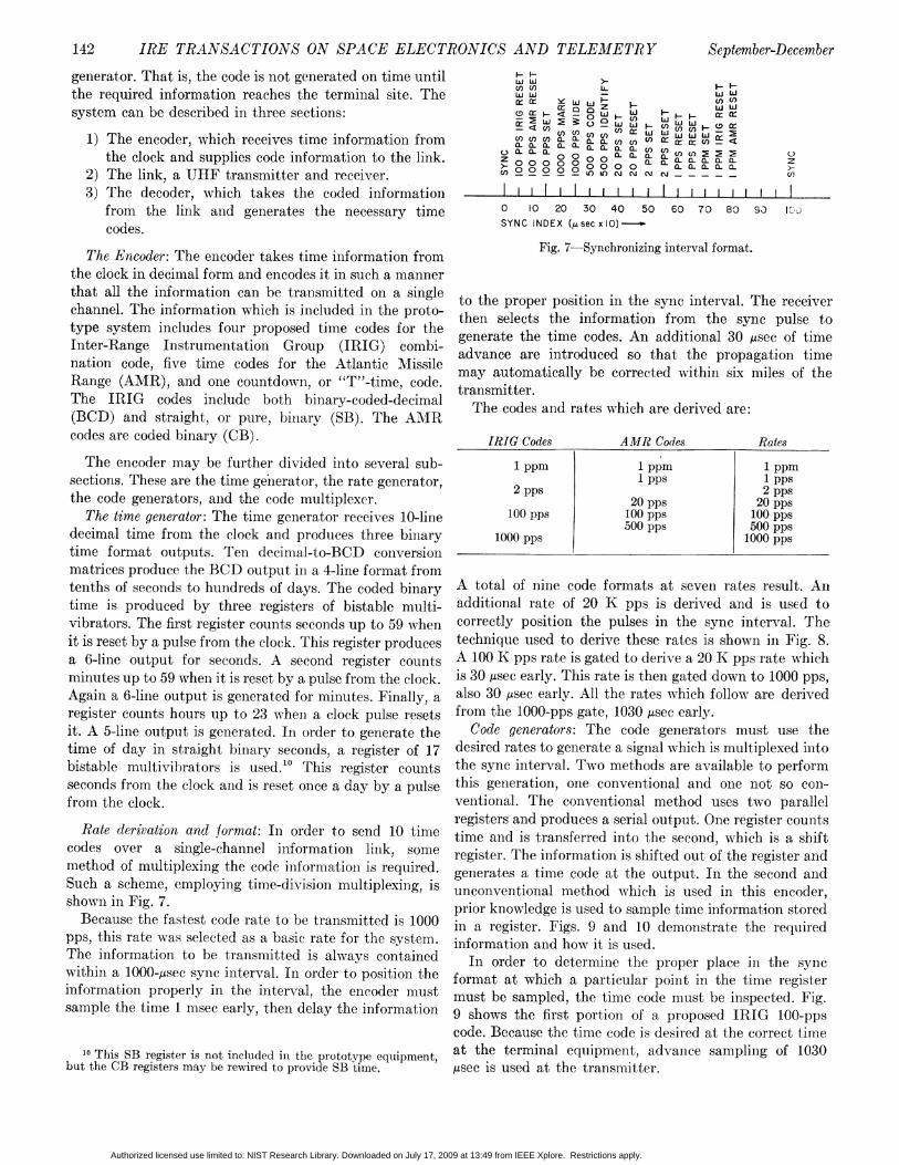
The Encoder: The encoder takes time information from Fig. 7-Synchronizing interval format.the clock in decimal form and encodes it in such a mannerthat all the information can be transmitted on a single to the proper position in the sync interval. The receiverchannel. The information which is included in the proto- then selects the information from the sync pulse totype system includes four proposed time codes for the generate the time codes. An additional 30 /Isec of timeInter-Range Instrumentation Group (IRIG) combi- advance are introduced so that the propagation timenation code, five time codes for the Atlantic Missile . . .Range (AMR), and one countdown, or "T"-time, code. transmitteriThe IRIG codes include both binary-coded-decimal The codes and rates which are derived are:(BCD) and straight, or pure, binarv (SB). The AMRcodes are coded binary (CB). IRIG Codes AMR Codes Rates
The encoder may be further divided into several sub- 1 ppm 1 ppm 1 ppmsections. These are the time ge'nerator, the rate generator, Ip pps pps2 pps 2 ~~~~~ppsthe code generators, and the code multiplexer. 20 pps 20 pps
The time generator: The time generator receives 10-line 100 pps 100 pps 100 ppsdeeimal time from the clock and produces three binary 1000 pps 0 5000 ppstime format outputs. Ten decimal-to-BCD conversionmatrices produce the BCD output in a 4-line format fromtenths of seconds to hundreds of days. The coded binary A total of nine code formats at seven rates result. Anitime is produced by three registers of bistable multi- additional rate of 20 K pps is derived and is used tovibrators. The first register counts seconds up to 59 when correctly position the pulses in the sync interval. Theit is reset by a pulse from the elock. This register produces technique used to derive these rates is shown in Fig. 8.a 6-line output for seconds. A second register counts A 100 K pps rate is gated to derive a 20 K pps rate whichminutes up to 59 -when it is reset by a pulse from the clock. is 30 /see early. This rate is then gated down to 1000 pps,Again a 6-line output is generated for minutes. Finally, a also 30 /sec early. All the rates which follow are derivedregister counts hours up to 23 when a clock pulse resets from the 1000-pps gate, 1030 ,usec early.it. A 5-line output is generated. In order to generate the Code generators: The code generators must use thetime of day in straight binary seconds, a register of 17 desired rates to generate a signal which is multiplexed intobistable multivibrators is used.'0 This register counts the sync interval. Two methods are available to performseconds from the clock and is reset once a day by a pulse this generation, one conventional and one not so con-from the clock. ventional. The conventional method uses two parallel
registers and produces a serial output. One register countsRate derivation and format: In order to send 10 time time and is transferred into the second, which is a shiftcodes over a single-channel information link, some register. The information is shifted out of the register andmethod of multiplexing the code information is required. generates a time code at the output. In the second andSuch a scheme, employing time-division multiplexing, is unconventional method which is used in this encoder,shown in Fig. 7. prior knowledge is used to sample time information storedBecause the fastesteode rate to be transmitted is 1000 in a register. Figs. 9 and 10 demonstrate the required
pps, this rate was selected as a basic rate for the system. information and how it is used.The information to be transmitted is always contained In order to determine the proper place in the syncwithin a 1000-gsee sync interval. In order to position the format at whieh a particular point in the time registerinformation properly in the interv7al, the enlcoder must must be sampled, the time code m1ust be inspected. Fig.sample the time 1 msec early, then delay the information 9 showvs the first portion of a proposed IRIG lOO-pps
code. Because the time code is desired at the correct time10 This SB register iS not included in the prototype equipment,atheerileqpmn,dvcespigof13
but the CB registers may be rewired to provide SB time. ,usec iS used at the transmiltter.
Authorized licensed use limited to: NIST Research Library. Downloaded on July 17, 2009 at 13:49 from IEEE Xplore. Restrictions apply.

1960 Davis and Doherty: WVidely Separated Clocks with Microsecond Synchronization 143DECADE DECADE DECADE 5 CODE INDEX COUNT 6NO TWO NO THREE NO FOUR O "I
IOOK PPS IOK PPS K PPS 4-TO2 msec. E )) b ) 4 _ ~~~~REMAININGII9 357,_0_/\S_ g DECADES jI 100 PPS (1030 j±sec EARLY)
*SILTC LA X10
SECOND BCD MATRIX OUTPUT -
TOCC
_-OTHEROv Lr|ATHER 000t°°° MILLISECOND (0.1 SECOND) DECADE OUTPUT1 . -
- ; 50 MILLISECOND (0.05 SECOND) DECADE OU20K 1000 500 100 SAMPLING GATE OUTPUTPPS PPS PPS PpS -
(30Msec EARLY) (30usec EARLY) (IO30/sec EARLY) 5 MILLISECOND RESET
CODE GENERATOR BISTABLE MULTIVIBRATORF;;negFig. 8-Rate generator. -OUTPUT TO CODE MULTIPLEXER
X
INDEX 50 51 52 53 54 55 56 57 58 59 60664 C_COUNT Fig. 11-Code generator timing diagram.0 2 3 4 5 6 7 8 9 10
This method will obviously only generate a ONE forthe time bits. Some simple method must be devised to
sec 2 4 8 l0 sec 20 40 generate ZEROS for the time bits and for all other indexCODE DIGIT counts except the reference marks as well as to generateWEIGHT the reference marks. Fig. 10 also shows the method used
Fig. 9-Example of a 100-pps time code. to generate a ZERO unless a ONE or a MARK is to begenerated. The rate, in this case 100 pps, is used to set abistable multivibrator whose output feeds a 3-input AND
MILLISECOND DECADE {°° 900 \ gate. This bistable multivibrator is reset after 2 msec.OUTPUTS 150 I 90 )M The other two inputs to the gate are inhibited by other10 sec ipt aeb
100 PPS 100 PPS bistable multivibrators, one for the ONE code and onefor the MARK. If neither bistable multivibrator is set
loo PPS S o by a ONE or a MARK pulse, then the output of the2 msec RESET R ZERO bistable multivibrator appears at the code output.
If either the ONE or MARK bistable multivibrator isI -S FF o >set,the ZERO output is inhibited. The ONE and MARK
5 msec RESET R I- are mutually exclusive, as is seen from the code format.TR GGER The reset pulses for the bistable multivibrators are
FF msec REET A R |MULTIPTOCODE derived from the clock divider. The "mark" set pulses are8 msec RESET -R MULTIPLEXER
derived in the same manner as the "one" pulses, exceptFig. 10-Example of a 100-pps time code generator. a 3-input AND gate is used."1
Code multiplexer: The code multiplexer takes theinformation from the nine code generators (four IRIG,
For example, in order for the 10-second bit to occur at five AMR) and multiplexes it onto a single channel forthe terminal equipment exactly on index count number broadcast over the UHF link. Fig. 12 shows a portion ofsix, the 10-second BCD output must be sampled during the multiplexer which demonstrates how this is acconmp-the index interval beginning on count five. Since, for this lished.code, index count five always corresponds to a time 50 The i000-pps rate, which synchronizes the receiver, ismsec after the second, outputs from the beam-switching fed directly to the code multiplexer output. The inputstubes in the divider are used to select this interval for from the code generators must each be delayed to itssampling. Fig. 10 shows the logical AND gate used to unique position in the sync interval. The informationsample this time, while Fig. 11 shows a timing diagram which is actually broadcast consists of set and resetof the sampling operation. In order to avoid ambiguity pulses. This information is derived from the rate and lengthbetween 50 msec and 150 or 250 msec, the zero output of the code generator output pulse. Since all codes of thefrom the tenth-second counter (marked as 000 msee) is same rate, regardless of format, turn on at the same timerused along with the number five output of the 10-mseccounter (marked as 50 msec). This sampling techniqueis used for each information bit in this code. "lSpecial techniques are used on the 500- and 1000-pps codes.
Authorized licensed use limited to: NIST Research Library. Downloaded on July 17, 2009 at 13:49 from IEEE Xplore. Restrictions apply.

144 IRE TRANSACTIONS ON SPACE ELECTRONICS AND TELEMETRY September-December
1000 PPS from the rest of the information and generates a rampoutput, and a time code demodulator, which uses theramp and sync pulses to examine the sync interval for
20K PPS I Ll information to generate a time code and rate output.The sync intertcal demodulator: The sync interval de-
TO UHFmodulator is required at. every site in order to separate
IDITRANSMI;TER the 1000-pps synlc pulses anid to generate the ramp which islooPPS s130,usec DT required for code demodulator.
s o _ > The broadcast code format is such that the last 100R8 FFyIsec of the sync interval are always vacant and alternate
sync intervals are usually vacant (Figs. 7 and 14). TheseFROM 100 PPS DMV empty spaces are used to simplify the synchronization ofCODE 3OseDTc
GENERATOR 30, 1sIcthe demodulator. The manner in which the sync demodu-lator operates is shown in Figs. 13 and 14. The first pulse,no matter when it occurs, passes through an AND gateand triggers a bootstrap ramp generator. The bootstrap
each rate is delayed to its correct position in the sync inhibits the gate for the length of the ramp, 900 tsec.interval and transmitted. The 20-K pps rate is used as a After the bootstrap has removed the gate inhibition, the
reference to correctly position the pulse exactly on a 50- next pulse is allowed through to repeat the cycle. If the
gsec mark in the interval. This is demonstrated for the first. pulse occurred in the middle of some particular sync
100-pps rate in Fig. 12. In order to generate the reset interval, then the ramp will turn off in the middle of the
pulse for the code, the output of the code generator is following interval, which will probably be empty. Fig. 14
differentiated to initiate its delay. Again, the 20-K pps shows how the unsynchronized ramp would be synchro-
rate is used to re-establish the system accuracy. This nized by the IF output using the sync pulses and empty
procedure is repeated for each rate and code. intervals.It should be noted that the relative position of the pulses The outputs which are produced by the sync interval
within the sync interval is immaterial. Bc cause of the demodulator are: first, the ramp, which is used to generatesystem logic, the set pulse will always occur in an interval the delays required for the code demodulator; second, the
which precedes the reset pulse. However, because of some sync pulses, which are used to synchronize the various
symplifications made in the demodulator, the 100-pps time codes within a microsecond; and third, a test pulse,reset pulses should appear as shown in Fig. 7. This will be which would be used as an aid for tests and alignment.
rdiscussed shortly. This test pulse is derived in exactly the same manner
The Insformation Link: The link must transmit the as the rate, or synchronized set, pulses in the code de-
information from the output of the encoder to the input modulator and is usually adjusted for a 1-pps output.of the decoder. A UHF distribution system is employed Time code and rate demodulator: The code demodulator
in the prototype system. This includes a single transmitter must take the outputs from the sync demodulator andat a central location and a receiver at each recording site. use them, along with the IF output, to generate the desired
The transmitter: The transmitter which is used in this time code. One such demodulator is required for each code
system is a simple pulsed cavity oscillator. A blocking output desired. Figs. 15 and 16 described the operationoscillator is used to pulse the cavity which operates at a ofa typical demodulator.'3frequency of 1.75 Ge.'2 A coaxial transmitting anten-na is The ramp output from the sync demodulator is used
mounted at a height above nearby obstacles. with a delay pickoff to select a portion of the sync interval
The receiver: The receiving antenna is a dipole mounted to be examined. The portion of the interval which is
in a corner reflector or horn. The antenna feeds a crystal examined is different for each code. Because of the manner
mixer. The local oscillator is another cavity oscillator in wvhich the codes are generated in the encoder, the set
which operates continuously. A 60-Mc IF strip provides pulse will occur in an interval which is several milliseconds
the required gain. The detected output from the IF strip ahead of the interval containing the reset pulse. Therefore,is fed directly to the input of the decoder. the relative position of the set and reset pulses in the sync
Using this relatively simple system, signals were interval is arbitrary. When a set pulse occurs in the interval
received at a range of 40 miles with a SNR of 20 db. at the point where the delay pickoff is sampling, a gate is
The Decoder: The decoder must take the output from opened which allows the next sync pulse to set a bistable
the receiver, separa.te the sync pulses, examine the synce multivibrator. This is the bistable multivibrator which
interval for information, and generate the time codes. produces t.he code output. This synchronized pulse occurs
Two units are used to perform these functions, a syncinterval demodulator, which separat.es the synlc pulses
'3 All the demodulators are identical except for the 500- and12 Gc = Gigacycles = 109 cps. i000-pps codes.
Authorized licensed use limited to: NIST Research Library. Downloaded on July 17, 2009 at 13:49 from IEEE Xplore. Restrictions apply.
1960 Davis and Doherty: Widely Separated Clocks with Mlicrosecond Synchronization 145
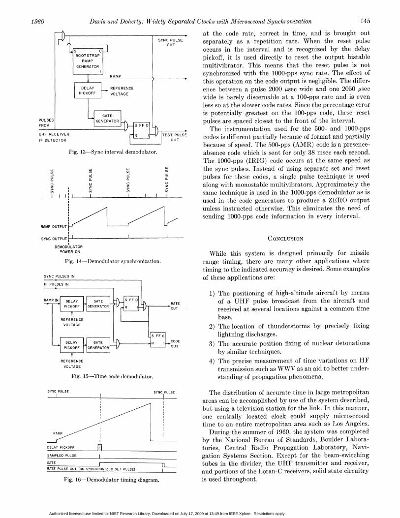
___________ at the code rate, correct in time, and is brought outSYNC PULSE separately as a repetition rate. When the reset pulseOUT a us
s o occurs in the interval and is recognized by the delayBOOTSTRAP pickoff, it is used directly to reset the output bistableGENERATOR multivibrator. This means that the reset pulse is not
RAMP synchronized with the 1000-pps sync rate. The effect ofthis operation on the code output is negligible. The differ-
DELAY _ REFERENCE ence between a pulse 2000 ,usec wide and one 2050 ysecPICKOFF VOLTAGE wide is barely discernable at a 100-pps rate and is even
less so at the slower code rates. Since the percentage errorXGATE I is potentially greatest on the 100-pps code, these reset
PULSES L GENERATOR pulses are spaced closest to the front of the interval.FROM SF
The instrumentation used for the 500- and 1000-ppsUHF RECEIVER R TEST PULSE codes is different partially because of format and partiallyIF DETECTOROU because of speed. The 500-pps (AMR) code is a presence-
Fig. 13-Sync interval demodulator. absence code which is sent for only 38 msec each second.The 1000-pps (IRIG) code occurs at the same speed as
U)the sync pulses. Instead of using separate set and reset
D D D D pulses for these codes, a single pulse technique is usedz 'J O O along with monostable multivibrators. Approximately the> cn I En same technique is used in the 1000-pps demodulator as is
used in the code generators to produce a ZERO outputunless instructed otherwise. This eliminates the need ofsending 1000-pps code information in every interval.
RAMP OUTPUT
SYNC OUTPUT CONCLUSION
DEMODULATORDOWER ON While this system is designed primarily for missile
Fig. 14-Demodulator synchronization. range timing, there are many other applications wheretiming to the indicated accuracy is desired. Some examplesSYNC PULSES IN of these applications are:
IF PULSES IN
1) The positioning of high-altitude aircraft by meansRAMPIN DELAY GATE S FF 0 RATE of a UHF pulse broadcast from the aircraft and
PICKOFF GENERATOR R OUT received at several locations against a common time
REFERENCE base.VOLTAGE 2) The location of thunderstorms by precisely fixing
S FF O lightning discharges.DELAY GATE R CODE 3) The accurate position fixing of nuclear detonationsPICKOFF GENERATOR OUT
S by similar techniques.REFERENCE 4) The precise measurement of time variations on HFVOLTAGE transmission such as WWV as an aid to better under-
Fig. 15-Time code demodulator. standing of propagation phenomena.
SYNC PULSE SYNC PULSE The distribution of accurate time in large metropolitanareas can be accomplished by use of the system described,
/', but using a television station for the link. In this manner,j one centrally located clock could supply microsecond
time to an entire metropolitan area such as Los Angeles.RAMP During the summer of 1960, the system was completed
'~~~~~~~~~~by the Ntational Bureau of Standards, Boulder Labora-DELAY PICKOFF mtories, Central Radio Propagation Laboratory, Navi-_______________PULSE_______I gation Systems Section. Except for the beam-switching
sArE ,l ~~~~~~~~tubesin the divider, the UHF transmitter and receivrer,RATE PLSEOU(OR SNCHRONZED SE PULSE and portions of the Loran-C receivers, solid state circuitry
Fig. 16-Demodullator timing diagram. is used throughout.
Authorized licensed use limited to: NIST Research Library. Downloaded on July 17, 2009 at 13:49 from IEEE Xplore. Restrictions apply.

146 IRE TRANSACTIONS ON SPACE ELECTRONICS AND TELEMETRY September-December
GLOSSARYJ FF O Bistable Multivibrator (flip-flop)J = set input can be used together
Logical OR Circuit K =K reset inputcE~~~~~~~~~~~~~~~~~~~~ T I
Monostable Multivibrator (one-shot or delay multi-Logical AXND Circuit G vibrator)
DMV S = set inputr sec G = gate outputS TDT = delayed trigger output
r = duration of delay
A Amplifier (no inversion)ACKNOWLEDGMENT
The authors wish to acknowledge the contributions ofEF Emitter Follower G. Hefley, R. F. Linfield, and E. L. Berger, all of NBS
Boulder Laboratories, and P. J. Kiser of Eastern GEEIARegion for their aid in the design and construction of the
Bistable Multivibrator(. f p-flop) equipment described. We also wish to thank E. KomarekS FF o S = set input I cannot be used together and W. Mansfield for their comments and suggestions on
R = reset inputf the manuscript. The figures were prepared under theR T T = toggle input (for svmmetrical triggering)
0 = output after reset' direetion of V. Brackett and the typing was done by Jane1 = output after set L. Rhomberg.
Geometric Aspects of Satellite Communication*F. W. SINDENt AND W. L. M\IAMMELt
Summary-If a system of communications satellites is uncon- movable antennas and switching from one satellite totrolled after launching, service interruptions are inevitable. The another as they appeared and disappeared over theamount of interruption depends on the number of satellites, their horizon. Bothsyseave lng listsofadv es andaltitude, the orbit inclinations, the distance between ground stations, horizon Both systems have long lists of advantages andthe acceptable signal-to-noise ratio, and other parameters. Various disadvantages. In the present paper we consider onlyrelations between these quantities are presented in tables and lowv-altitude systems.graphs, and are illustrated by examples. It is not necessary for low-altitude satellites to carry
electronic equipment. Simple reflectors, though theyrequire large transmitter power, do not appear infeasible,
I. INTRODUCTION and have the tremendous advantage of simplicity. Ex-
Tr HE IDEA of using artificial earth satellites to periments oni 100-foot metal-coated mylar balloonis arelrelay radio messages of various kinds is being currently being conducted. Many questions on meteorseriously studied. Either of two systems appears pun-cturinig, drag, etc., remain to be answered, but at the
feasible. One would consist of two or three satellites at present time, balloon satellites appear promising. In the22,000 miles, and the other would consist of a great many present paper we consider mainly satellites of this type,satellites at one or two thousand miles. A satellite at just though some of the results apply also to satellites bearingthe right altitude (- 22,000 miles) would make one electronic equipmeent.revolution in 24 hours, and if its orbit were in the plane Plane waves impinging on a sphere are reflected veryof the equator, it wvould appear to remain stationary. nearly isotropically if the wavelength is small comparedFixed antennas pointed at the satellite could be used to to the diameter of the sphere. Hence signals reflected fromommunicate between distant points on earth. The an orbiting mylar balloon will be available to the receiver
other system wvould require tracking the satellites wvith as long as the balloon is in sight. When it disappears toeither the transmitter or the receiver, both will have toszritch simultaneously to a new satellite. If no other
* ReceivdbythPGSET, ugust 1, 1960.satellite is available, service will necessarily be interruptedt Bell Telephone Labs., Inc., Murray Hill, N. J. until one appears.
Authorized licensed use limited to: NIST Research Library. Downloaded on July 17, 2009 at 13:49 from IEEE Xplore. Restrictions apply.