wheel move carriage-style - ag growth
TRANSCRIPT

Read this manual before using product. Failure to follow instructions and safety precautions can result in serious injury, death, or property damage. Keep manual for future reference.
CARRIAGE-STYLE WHEEL MOVE1330, 1335, 1340, 1345, 1535, 1540 & 1545 SERIESASSEMBLY & OPERATION MANUAL
Part Number: P1512103 R1Revised: Jun/13

ORIGINAL INSTRUCTIONS
This product has been designed and constructed according to general engineering standardsa. Other local regulations may apply and must be followed by the operator. We strongly recommend that all personnel associated with this equipment be trained in the correct operational and safety procedures required for this product. Periodic reviews of this manual with all employees should be standard practice. For your convenience, we include this sign-off sheet so you can record your periodic reviews.
Date Employee Signature Employer Signature

a. Standards include organizations such as the American Society of Agricultural and Biological Engineers, American National Standards Institute, Canadian Standards Association, International Organization for Standardization, and/or others.
This product has been designed and constructed according to general engineering standardsa. Other local regulations may apply and must be followed by the operator. We strongly recommend that all personnel associated with this equipment be trained in the correct operational and safety procedures required for this product. Periodic reviews of this manual with all employees should be standard practice. For your convenience, we include this sign-off sheet so you can record your periodic reviews.


TABLE OF CONTENTS
BATCO - CARRIAGE-STYLE WHEEL MOVE 1330, 1335, 1340, 1345, 1535, 1540 & 1545 SERIES
1. Introduction .......................................................................................................................... 9
2. Safety .................................................................................................................................. 112.1. General Safety Information .................................................................................... 112.2. Assembly Safety..................................................................................................... 122.3. Operation Safety .................................................................................................... 122.4. Placement Safety ................................................................................................... 132.5. Maintenance Safety................................................................................................ 142.6. Hydraulic Safety ..................................................................................................... 152.7. Transport Safety..................................................................................................... 162.8. Storage Safety........................................................................................................ 182.9. Engine Safety ......................................................................................................... 182.10. Tire Safety ............................................................................................................ 182.11. Safety Decals ....................................................................................................... 18
2.11.1. Decal Installation .................................................................................... 182.11.2. Safety Decal Locations........................................................................... 19
P1512103 R1 5

TABLE OF CONTENTS
BATCO - CARRIAGE-STYLE WHEEL MOVE 1330, 1335, 1340, 1345, 1535, 1540 & 1545 SERIES
3. Assembly ............................................................................................................................ 213.1. Pre-Assembly ......................................................................................................... 21
3.1.1. General ..................................................................................................... 213.1.2. Crimping Tubes ........................................................................................ 22
3.2. Frame Assembly..................................................................................................... 223.2.1. Axle Preparation ....................................................................................... 243.2.2. Undercarriage Assembly .......................................................................... 253.2.3. Hydraulic Cylinder Assembly .................................................................... 283.2.4. Steering Sub-Assembly ............................................................................ 29
3.3. Pump and Tank Assembly...................................................................................... 313.3.1. Hanging Gas............................................................................................. 313.3.2. Axle Gas ................................................................................................... 333.3.3. Direct Drive ............................................................................................... 35
3.4. Gear Pump Mount & Guard.................................................................................... 373.4.1. Gear Pump Installation ............................................................................. 373.4.2. Pump Guard Installation ........................................................................... 38
3.5. Valve....................................................................................................................... 383.5.1. Ram Speed Adjustment............................................................................ 38
3.6. Winch...................................................................................................................... 403.6.1. Winch Assembly ....................................................................................... 403.6.2. Winch Alignment....................................................................................... 403.6.3. Operation and Adjustment of Winch Valve ............................................... 41
3.7. Wheel Move Drive System ..................................................................................... 423.8. Gear Drive .............................................................................................................. 44
3.8.1. Gear Drive Installation .............................................................................. 443.8.2. Over-Center Drive Installation .................................................................. 453.8.3. Pinion Gear Adjustment............................................................................ 463.8.4. Cushion Valve Assembly & Operation...................................................... 47
3.9. Hydraulic Hose Assembly....................................................................................... 483.10. Wiring - Direct Drive Wheel Moves....................................................................... 51
3.10.1. Onan/Linamar Engine............................................................................. 523.10.2. Honda Engine ......................................................................................... 54
4. Transport & Placement ..................................................................................................... 554.1. Transport Procedure............................................................................................... 554.2. Placement Procedure ............................................................................................. 56
5. Operation ............................................................................................................................ 595.1. Pre-Operation Checklist ......................................................................................... 595.2. Start-Up & Break-In ................................................................................................ 595.3. Operating Procedure .............................................................................................. 605.4. Weather .................................................................................................................. 61
6. Maintenance and Storage ................................................................................................. 636.1. Maintenance Procedure ......................................................................................... 636.2. Storage Procedures................................................................................................ 63
6 P1512103 R1

BATCO - CARRIAGE-STYLE WHEEL MOVE 1330, 1335, 1340, 1345, 1535, 1540 & 1545 SERIES
7. Troubleshooting ................................................................................................................. 65
8. Appendix............................................................................................................................. 678.1. Bracket Locations................................................................................................... 678.2. Bolt Torque............................................................................................................. 68
New Equipment Warranty ....................................................................................................... 69
P1512103 R1 7

BATCO - CARRIAGE-STYLE WHEEL MOVE 1330, 1335, 1340, 1345, 1535, 1540 & 1545 SERIES
8 P1512103 R1

BATCO - CARRIAGE-STYLE WHEEL MOVE 1. INTRODUCTION1330, 1335, 1340, 1345, 1535, 1540 & 1545 SERIES
1. IntroductionCongratulations on your choice of a Batco wheel move to complement your agricultural operation. This equipment has been designed and manufactured to meet the needs of the discriminating buyer for the efficient movement of the 13 and 15 Series Grain Conveyors.
Safe, efficient, and trouble-free operation of your wheel move requires that you, and anyone else who will be involved with assembling the wheel move; read and understand the safety, assembly, and operation procedures contained within the manual.
Keep this manual handy for frequent reference and to pass on to new operators or owners. Call your Batco distributor or dealer if you need assistance, infor-mation, or additional copies of the manual.
Operator Orientations: directions left, right, front, and rear, as mentioned throughout this manual, are as seen from the tractor driver seat facing in the direction of travel when the unit is being transported.
This manual is a supplement to the Batco Conveyor Assembly Manual. Please refer to that manual for safety precautions before assembling the wheel move kit.
P1512103 R1 9

1. INTRODUCTION BATCO - CARRIAGE-STYLE WHEEL MOVE 1330, 1335, 1340, 1345, 1535, 1540 & 1545 SERIES
10 P1512103 R1

BATCO - CARRIAGE-STYLE WHEEL MOVE 2. SAFETY1330, 1335, 1340, 1345, 1535, 1540 & 1545 SERIES 2.1. GENERAL SAFETY INFORMATION
2. Safety2.1. GENERAL SAFETY INFORMATION
The Safety Alert symbol identifies important safety messages on the product and in the manual. When you see this symbol, be alert to the possibility of personal injury or death. Follow the instructions in the safety messages.
Why is SAFETY important?
• Accidents disable and kill.• Accidents cost.• Accidents can be avoided.
SIGNAL WORDS: Note the use of the signal words DANGER, WARNING, CAUTION, and NOTICE with the safety messages. The appropriate signal word for each message has been selected using the definitions below as a guideline.
DANGER
Indicates an imminently hazardous situation that, if not avoided, will result in serious injury or death.
WARNING
Indicates a hazardous situation that, if not avoided, could result in serious injury or death.
CAUTION
Indicates a hazardous situation that, if not avoided, may result in minor or moderate injury.
NOTICE
Indicates a potentially hazardous situation that, if not avoided, may result in property damage.
P1512103 R1 11

2. SAFETY BATCO - CARRIAGE-STYLE WHEEL MOVE2.2. ASSEMBLY SAFETY 1330, 1335, 1340, 1345, 1535, 1540 & 1545 SERIES
YOU are responsible for the SAFE use and maintenance of your equipment. YOU must ensure that you and anyone else who is going to work around the equipment understands all procedures and related SAFETY information contained in this manual.
Remember, YOU are the key to safety. Good safety practices not only protect you, but also the people around you. Make these practices a working part of your safety program.
Important: Below are general instructions that apply to all safety practices. Any instructions specific to a certain safety practice (e.g., Operational Safety), can be found in the appropriate section. Always read the complete instructional sections and not just these safety summaries before doing anything with the equipment.
• It is the equipment owner, operator, and maintenance personnel's responsi-bility to read and understand ALL safety instructions, safety decals, and man-uals and follow them when assembling, operating, or maintaining the equipment. All accidents can be avoided.
• Equipment owners must give instructions and review the information initially and annually with all personnel before allowing them to operate this product. Untrained users/operators expose themselves and bystanders to possible serious injury or death.
• Use this equipment for its intended purposes only.• Do not modify the equipment in any way without written permission from the
manufacturer. Unauthorized modification may impair the function and/or safety, and could affect the life of the equipment. Any unauthorized modifica-tion of the equipment voids the warranty.
• Do not allow any unauthorized person in the work area.
2.2. ASSEMBLY SAFETY
• Read and understand the instructions to get to know the sub-assemblies and hardware that make up the equipment before preceding to assemble the product.
• Do not take chances with safety. The components are large, heavy, and can be hard to handle. Always use the proper tools, stands, jacks, and hoists for the job.
• Always have two or more people assembling the equipment. Because of the weight, do not attempt assembly alone.
2.3. OPERATION SAFETY
• Have another person nearby who can shutdown the equipment in case of accident.
• For powered products: before servicing, adjusting, or repairing, unplug and place in neutral or off position, stop the engine or motor, remove ignition key, or lock out power source and wait for all moving parts to stop.
• Be familiar with machine hazard area. If anyone enters hazard areas, shut down machines immediately. Clear the area before restarting.
12 P1512103 R1

BATCO - CARRIAGE-STYLE WHEEL MOVE 2. SAFETY1330, 1335, 1340, 1345, 1535, 1540 & 1545 SERIES 2.4. PLACEMENT SAFETY
• Keep hands, feet, hair, and clothing away from all moving and/or rotating parts.
• Do not allow riders on the conveyor, tractor, or towing vehicle when transport-ing.
• Stay away from overhead obstructions and power lines during operation and transporting. Electrocution may occur without direct contact.
• Do not operate machine when any guards are removed.• Set park brake on tractor before starting.• Lower conveyor to its lowest position before moving or transporting or when
not in use.• Inspect lift cable (if equipped) before using conveyor. Replace if frayed or
damaged.• Be sure that conveyor is empty before raising or lowering.
2.4. PLACEMENT SAFETY
• Move conveyor only with a tractor/towing vehicle. The only exception is mov-ing a Top Drive conveyor, since these units are balanced differently.
• Stay away from overhead power lines when moving conveyor. Electrocution can occur without direct contact.
• Chock conveyor and tractor wheels front and rear before operating.• Keep conveyor as low as possible when moving. Raise only when it is next to
storage facility.• Be familiar with the machine hazard area. If anyone enters hazard area, shut
down machine immediately. Clear the area before restarting.• Operate the conveyor on level ground free of debris. If ground is uneven,
anchor the conveyor to prevent tipping or upending.
WARNING
When releasing conveyor from the towing vehi-cle, test the intake end for downward weight.
Do not raise the intake end above drawbar height. Conveyor upending may occur.
P1512103 R1 13

2. SAFETY BATCO - CARRIAGE-STYLE WHEEL MOVE2.5. MAINTENANCE SAFETY 1330, 1335, 1340, 1345, 1535, 1540 & 1545 SERIES
Figure 2.1 Workplace Hazard Area (Electric/Gas Drive)
2.5. MAINTENANCE SAFETY
• Place all controls in neutral or off, stop engine or motor, remove ignition key or disable power source and wait for all moving parts to stop before servicing, adjusting, or repairing.
• Before applying pressure to a hydraulic system, make sure all components are tight and that hoses and couplings are in good condition.
• Relieve pressure from hydraulic circuit before servicing or disconnecting from tractor.
• Place stands or blocks under the frame before working beneath the machine.
14 P1512103 R1

BATCO - CARRIAGE-STYLE WHEEL MOVE 2. SAFETY1330, 1335, 1340, 1345, 1535, 1540 & 1545 SERIES 2.6. HYDRAULIC SAFETY
• Support conveyor tube before attempting maintenance on the undercarriage assembly. Where possible, conveyor should be in the full down position.
• After maintenance is complete, replace and secure all safety guards and safety devices.
• Remove all tools and unused parts from machine before operation.• Remove buildup of grease, oil, and debris.• Inspect all parts. Ensure parts are in good condition and installed properly.• New safety decals must be applied if old decals have been damaged,
removed, become illegible, or if any parts with decals have been replaced. New safety decals are available from your distributor, dealer, or factory.
Use only genuine Batco replacement parts or equivalent. Replacement parts must meet ASAE standards or serious injury may result. Use of unauthorized parts will void the warranty. If in doubt, contact Batco or your Batco dealer.
Do not modify the equipment. Unauthorized modification may impart the function or safety of the equipment, could affect the life of the equipment, and will void your warranty.
2.6. HYDRAULIC SAFETY
• Always place all hydraulic controls in neutral and relieve system pressure before disconnecting from tractor or working on hydraulic system.
• Keep all components in the hydraulic system tightly secured, clean and in good condition.
• Replace any worn, cut, abraded, flattened or crimped hoses.• Do not attempt any makeshift repairs to the hydraulic fittings or hoses by
using tape, clamps or adhesive. The hydraulic system operates under extremely high-pressure; such repairs will fail suddenly and create a hazard-ous and unsafe condition.
• Wear proper hand and eye protection when searching for a high-pressure hydraulic leak. Use a piece of wood or cardboard as a backstop instead of hands to isolate and identify a leak.
• Before moving a hydraulic cylinder, ensure that the attached component is safely secured.
WARNING
Hydraulic fluid can cause serious injury if it penetrates the skin. If it does, see a doctor immediately. • Relieve pressure before disconnecting
hydraulic line.• Wear proper hand and eye protection and
use wood or cardboard, not hands, when searching for leaks.
P1512103 R1 15

2. SAFETY BATCO - CARRIAGE-STYLE WHEEL MOVE2.7. TRANSPORT SAFETY 1330, 1335, 1340, 1345, 1535, 1540 & 1545 SERIES
2.7. TRANSPORT SAFETY
• Read and understand all the information in the operation manual regarding procedures and safety when moving or transporting the conveyor.
• Check with local authorities regarding transport on public roads. Obey all applicable laws and regulations.
• Before raising/lowering/moving the conveyor, make sure the area around the conveyor is clear of obstructions and/or unauthorized personnel. Never allow anyone to stand on or beneath conveyor while transporting or placing con-veyor.
• Wheels must be free to move when raising or lowering conveyor.• Do not stand between towing vehicle and conveyor when hitching. • Make certain that the hitch pin is in place and the safety chain is properly
attached. Use a type of hitch pin that will not permit conveyor to separate from towing vehicle.
• Attach conveyor to towing vehicle with a pin and retainer. Always attach safety chain(s).
• Fully lower conveyor before transporting. • Always travel at a safe speed. Do not exceed 20 mph (32 km/h). Reduce
speed on rough roads and surfaces. Use caution when making corners or meeting traffic. Discharge end can swing dramatically on sharp corners. Ensure you are clear of obstructions and oncoming traffic.
• Use extreme care and minimum ground speed when operating or transport-ing on hillsides, over rough ground, or near ditches or fences.
• Always attach an SMV (slow moving vehicle) sign before transporting con-veyor, and equip the conveyor with the necessary lights for transportation where required by law. Always use hazard warning flashers on the tractor/towing vehicle when transporting unless prohibited by law.
• Do not allow riders on the conveyor, the tractor/towing vehicle or skid steer during transport.
• Stay away from overhead obstructions and power lines when operating and transporting. Electrocution can occur without direct contact.
• Long conveyors have a large turning radius. Allow ample room for turning, as discharge end may swing dramatically.
• Review the work safety area diagram before starting work.
16 P1512103 R1

BATCO - CARRIAGE-STYLE WHEEL MOVE 2. SAFETY1330, 1335, 1340, 1345, 1535, 1540 & 1545 SERIES 2.7. TRANSPORT SAFETY
Figure 2.2 Transport Hazard Area
P1512103 R1 17

2. SAFETY BATCO - CARRIAGE-STYLE WHEEL MOVE2.8. STORAGE SAFETY 1330, 1335, 1340, 1345, 1535, 1540 & 1545 SERIES
2.8. STORAGE SAFETY
• Store the unit in an area away from human activity.• Do not permit children to play on or around the stored machine.• Fully lower conveyor before storing.
2.9. ENGINE SAFETY
• Be sure to stop engine and remove key or lock out power before inspecting or servicing engine
• Refer to engine operation manual for further details.
2.10. TIRE SAFETY
1. Failure to follow proper procedures when mounting a tire on a wheel or rim can produce an explosion that may result in serious injury or death.
2. Do not attempt to mount a tire unless you have the proper equipment and experience to do the job.
3. Have a qualified tire dealer or repair service perform required tire maintenance.
4. When replacing worn tires, make sure they meet the original tire specifi-cations. Never under size the replacement tire.
5. Do not weld to tire rim with the tire mounted on rim. This action may cause an explosion which could result in serious injury or death.
6. Inflate tires to the manufacturer's recommended pressure.
2.11. SAFETY DECALS
• Keep safety decals clean and legible at all times.• Replace safety decals that are missing or have become illegible. See decal
location figures that follow.• Replaced parts must display the same decal(s) as the original part.• Safety decals are available from your distributor, dealer, or factory.
2.11.1. DECAL INSTALLATION
1. Decal area must be clean and dry, with a temperature above 50°F (10°C).2. Decide on the exact position before you remove the backing paper.3. Align the decal over the specified area and carefully press the small portion
with the exposed sticky backing in place.4. Slowly peel back the remaining paper and carefully smooth the remaining
portion of the decal in place.5. Small air pockets can be pierced with a pin and smoothed out using the sign
backing paper.
18 P1512103 R1

BATCO - CARRIAGE-STYLE WHEEL MOVE 2. SAFETY1330, 1335, 1340, 1345, 1535, 1540 & 1545 SERIES 2.11. SAFETY DECALS
2.11.2. SAFETY DECAL LOCATIONS
Replicas of the safety decals that are attached to the equipment are shown in the figure(s) that follow. Proper safety procedures require that you familiarize yourself with the various safety decals and the areas or particular functions that the decals apply to, as well as the safety precautions that must be taken to avoid serious injury, death, or damage.
Batco reserves the right to update safety decals without notice. Safety decals may not be exactly as shown.
P1512103 R1 19

2. SAFETY BATCO - CARRIAGE-STYLE WHEEL MOVE2.11. SAFETY DECALS 1330, 1335, 1340, 1345, 1535, 1540 & 1545 SERIES
DECAL # P1513022
DECAL # P1513028
DECAL # P1513008 DECAL # P1513002
DECAL # P1513008
20 P1512103 R1

BATCO - CARRIAGE-STYLE WHEEL MOVE 3. ASSEMBLY1330, 1335, 1340, 1345, 1535, 1540 & 1545 SERIES 3.1. PRE-ASSEMBLY
3. Assembly
Before starting the assembly of your wheel move, please read the following instructions carefully, and familiarize yourself with all the sub-assemblies and hardware making up the wheel move.
When tightening all fasteners, See Section 8.2. for proper torque specifications.
3.1. PRE-ASSEMBLY
3.1.1. GENERAL
1. Select an assembly area that is level, has a firm or hard surface, and is free of debris. Be sure it is large enough to allow access from all sides when the components are being assembled.
2. Bring all the tools, blocks, stands, jacks and hoists to the assembly area before starting.
3. The following tools and equipment are required to assemble the machine:
WARNING Before continuing, ensure you have read and understand the relevant information in the safety section. Safety information is provided to help prevent serious injury, death, or property damage.
3 standard socket set and wrench set 1 torque wrench1 standard 25’ (7.62 m) tape measure1 2’ (0.61 m) level1 tire gauge1 tire chuck
CAUTION
Ensure conveyor is in fully lowered position with hopper end on the ground before proceeding with the assembly of the wheel move.
P1512103 R1 21

3. ASSEMBLY BATCO - CARRIAGE-STYLE WHEEL MOVE3.2. FRAME ASSEMBLY 1330, 1335, 1340, 1345, 1535, 1540 & 1545 SERIES
3.1.2. CRIMPING TUBES
Note: During the installation of all u-clamps (3) on the grain conveyor tubes, they will need to be tightened until the tube begins to deform or crimp. This locks the u-clamps into place to prevent loosening during operation. The term “crimp” will be used to describe this technique throughout this manual. (See Figure 3.1).
3.2. FRAME ASSEMBLY
Figure 3.1 U-Clamp
Table 3.1 Carriage-Style Wheel Move FrameITEM DESCRIPTION PART NUMBER P/P STR
1 AXLE 30-45 13030100 1 12 AXLE TAB RIGHT 13120012 1 12 AXLE TAB LEFT 13120013 1 13 BOLT HEX 1/2” X 1-1/2” P0115013 2 24 NUT NYLOCK 1/2” P0134008 2 25 CROSSBRACE CLAMP BAND P020200321 2 26 V-FRAME P020202038 1 17 TRANSPORT PIPE (35 STD, FL) P020200319-76 2 27 TRANSPORT PIPE (45 STD, FL) P020200319-101 2 28 TIRE AND RIM P029900316A 2 69 BOLT HEX 3/8” X 1-1/2” P0115047 2 2
10 BOLT HEX 3/8” X 1” P0115046 6 611 NUT NYLOCK 3/8” P0134006 8 812 BOLT HEX 1/2” X 1-1/2” P0115013 2 213 CROSSBRACE P020200320 2 214 BOLT HEX 3/8” X 2” GR8 P0118050 2 215 NUT NYLOCK 3/8” P0134006 2 216 WHEEL MOVE SUSPENSION BRACKET 15010067 1 117 2” U-CLAMP 13012002 2 218 BOLT 1/2” X 2-1/2” GR8 P0118017 4 419 LOCKNUT 1/2” P0134008 4 420 HYDRAULIC CYLINDER P020200308 2 221 BOLT HEX 1/2” X 2-1/2” P0118017 2 222 NUT NYLOCK 1/2” P0134008 2 223 BOLT HEX 3/8” X 2” P0118050 2 224 NUT NYLOCK 3/8” P0134006 2 225 BAR HANDLE P020200305 1 -26 VALVE 3 SPOOL - TWO HANDLE P0861009 1 -
22 P1512103 R1

BATCO - CARRIAGE-STYLE WHEEL MOVE 3. ASSEMBLY1330, 1335, 1340, 1345, 1535, 1540 & 1545 SERIES 3.2. FRAME ASSEMBLY
27 SWIVEL 8 ORB X 1/2” F 90 P0820012 1 -28 BOLT HEX 5/16” X 3” P0115064 3 -29 CONTROL HANDLE P020200303 1 -30 ELBOW 6 ORB X 3/8” JIC P0820611 6 -31 SWIVEL 8 ORB X 1/2” F 90 P0820012 1 -32 CONTROL PANEL RING P020200301E 11 -33 NUT NYLOCK 5/16” P0134005 3 -34 RAM EXTENSION (35 STD, FL) 13120014 1 134 RAM EXTENSION (45 STD) 13120015 1 134 RAM EXTENSION (45 FL) 13120016 1 135 WHEEL YOKE WELDMENT P020200314A 2 236 1" COLLAR P029900248 2 237 BOLT HEX 3/4” X 6” P0115044 2 238 NUT NYLOCK 3/4” P0134012 2 239 TANDEM AXLE WITH BEARINGS P0202015-2 - 240 DOUBLE WHEEL YOKE P020202020 - 241 BOLT HEX 3/8” X 2” P0115050 - 242 BOLT 1/2” X 1-1/2” P0115013 - 243 STEERING SUB-ASSEMBLY - - 144 BOLT 3/8” X 2” P0115050 - 445 NUT NYLOCK 3/8” P0134006 - 446 AXLE CAP FOR OVERCENTER P11130185 - 247 LOCK WASHER 1/2” P0152008 - 248 BOLT 1/2” X 2” GR8 P0118016 - 249 NUT NYLOCK 3/8” P0134006 - 250 NUT NYLOCK 1/2” P0134008 - 251 NUT NYLOCK 1/2” P0134008 2 252 STEERING BAR P020202023 - 153 STEERING BAR COLUMN WITH BEARINGS P020202021 - 154 STEERING COLUMN PLATE P020202021-1 - 1
55A YOKE LINK ARM P020206004 - 255B STEERING STOP P020202024 - 156 BOLT 1/2” X 2” GR8 P0118016 - 157 NUT NYLOCK 1/2” P0134008 - 158 BOLT HEX 1/2” X 1-1/2” P0115013 - 259 NUT NYLOCK 1/2” P0134008 - 260 BOLT HEX 3/8” X 2” P0118050 - 161 NUT NYLOCK 3/8” P0134006 - 162 TIE ROD END (BALL JOINT) 1/2” P020202063 - 262 1/2” X 8” ROD P020202022-2 - 1
Table 3.1 Carriage-Style Wheel Move Frame
P1512103 R1 23

3. ASSEMBLY BATCO - CARRIAGE-STYLE WHEEL MOVE3.2. FRAME ASSEMBLY 1330, 1335, 1340, 1345, 1535, 1540 & 1545 SERIES
Figure 3.2 Carriage-Style Wheel Move Frame
3.2.1. AXLE PREPARATION
RETROFIT ASSEMBLY (Figure 3.3)
1. Prepare axle (1) for axle tabs (2) by removing paint from surface where the tabs are to be welded.
2. Install ring gear. See “Gear Drive Installation” on page 44 for details.3. Weld the axle tabs to the axle at the dimensions A and B shown in Figure 3.3.
Touch up paint.
24 P1512103 R1
BATCO - CARRIAGE-STYLE WHEEL MOVE 3. ASSEMBLY1330, 1335, 1340, 1345, 1535, 1540 & 1545 SERIES 3.2. FRAME ASSEMBLY
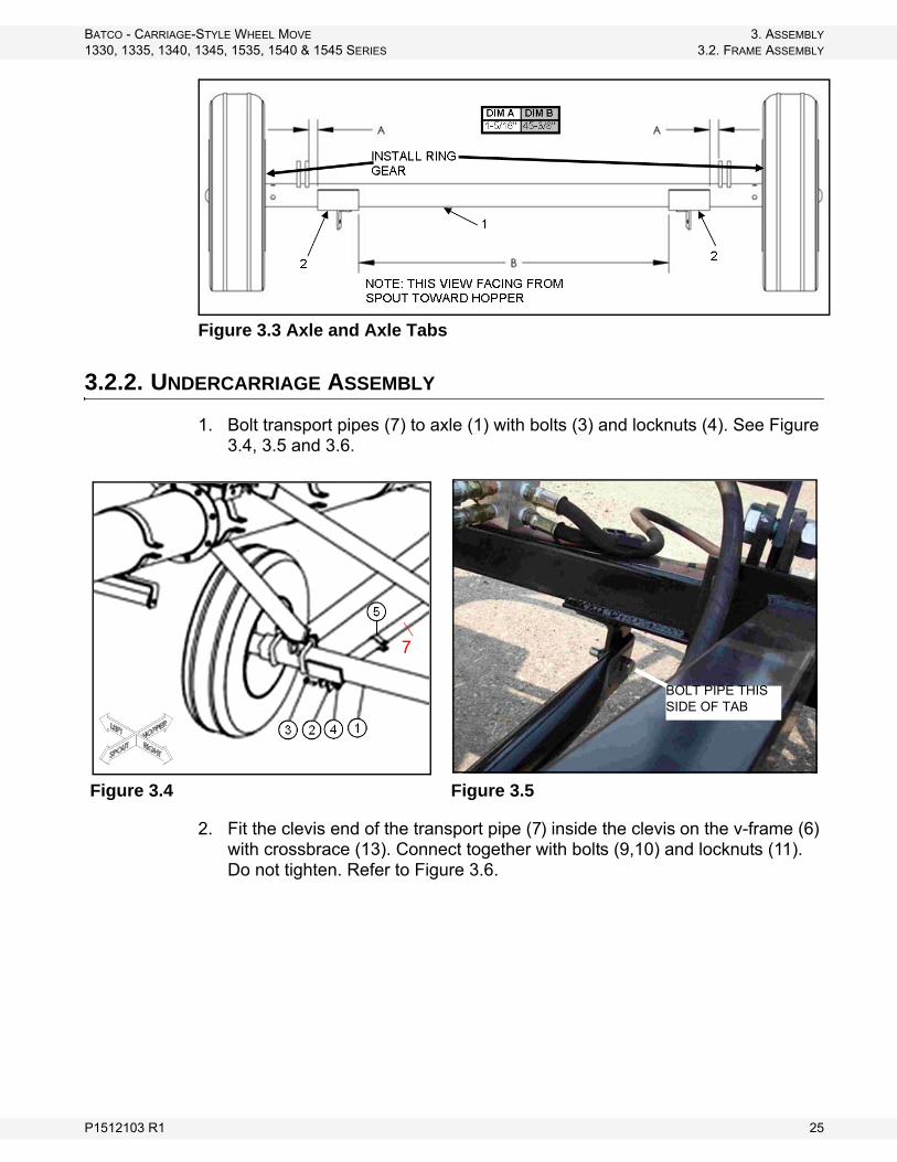
Figure 3.3 Axle and Axle Tabs
3.2.2. UNDERCARRIAGE ASSEMBLY
1. Bolt transport pipes (7) to axle (1) with bolts (3) and locknuts (4). See Figure 3.4, 3.5 and 3.6.
2. Fit the clevis end of the transport pipe (7) inside the clevis on the v-frame (6) with crossbrace (13). Connect together with bolts (9,10) and locknuts (11). Do not tighten. Refer to Figure 3.6.
Figure 3.4 Figure 3.5
7
BOLT PIPE THIS SIDE OF TAB
P1512103 R1 25

3. ASSEMBLY BATCO - CARRIAGE-STYLE WHEEL MOVE3.2. FRAME ASSEMBLY 1330, 1335, 1340, 1345, 1535, 1540 & 1545 SERIES
Figure 3.6
3. Attach the opposite end of the crossbrace (13) to the transport tube using clamp bands (5), bolts (14), and locknuts (15). Refer to Figure 3.7.
Figure 3.7
4. Attach the cross brace (13) to the v-frame (6) and mount one to the top side of the v-frame clevis and the other to the bottom. See Figure 3.6.
5. Connect the ram extension (34) to v-frame pipe (6) with bolts (12) and locknuts (51). See Figure 3.8.
Figure 3.8
13
12, 5134
26 P1512103 R1

BATCO - CARRIAGE-STYLE WHEEL MOVE 3. ASSEMBLY1330, 1335, 1340, 1345, 1535, 1540 & 1545 SERIES 3.2. FRAME ASSEMBLY
6. Loosely attach the wheel move suspension bracket (16) to the tube with u-clamps (17), bolts (18), and locknuts (19) at the dimension described in “Bracket Locations” on page 67. See Figure 3.9.
Figure 3.9
7. Push/Pull Systems: Bolt the control panel ring (32) to the tube. Do not tighten the bolts yet. Attach parts (25-33) to control panel ring (32). See Figure 3.10. See “Valve” on page 38 for details.
Figure 3.10
P1512103 R1 27

3. ASSEMBLY BATCO - CARRIAGE-STYLE WHEEL MOVE3.2. FRAME ASSEMBLY 1330, 1335, 1340, 1345, 1535, 1540 & 1545 SERIES
8. Push/Pull Systems: Install wheel yoke weldment (35) on v-frame, see Figure 3.6. Secure collar (36). Install tire (8) with bolt (37) and locknut (38). Repeat for opposite side.
3.2.3. HYDRAULIC CYLINDER ASSEMBLY
Figure 3.11
1. Connect the fully retracted cylinders (20) to the wheel move suspension bracket (16) and to the ram extension (34) with hardware supplied (21-24). See Figure 3.11.
2. Elevate the V-frame, undercarriage pipes, and ram assembly to form a straight line (transport position) as shown in Figure 3.12. Tighten the wheel move suspension bracket bolts.
Figure 3.12
16
34
28 P1512103 R1

BATCO - CARRIAGE-STYLE WHEEL MOVE 3. ASSEMBLY1330, 1335, 1340, 1345, 1535, 1540 & 1545 SERIES 3.2. FRAME ASSEMBLY
3.2.4. STEERING SUB-ASSEMBLY
Refer to Table 3.2 for the quantity of each component used and Figures 3.13 and 3.14 for the installation of the steering sub-assembly.
1. Connect the steering link arm and tie rod linkage to the assembly with a 1/2” x 1-1/2” bolt and locknut, and 1/2” x 2” bolts and locknuts, respectively.
2. Build the steering assembly as follows (Figure 3.13):a. Attach the three spool valve (4) to the wheel move handle (1) with 5/16” x
2-1/2” bolts and locknuts (5,6).b. Place 45° elbows (8) in three-spool valve (4).c. Install swivels (7) on three spool valve.d. Slide steering stop (3) on wheel move handle, do not secure set screw.
Figure 3.13
3. Install the steering assembly to the yoke link arm with a 1/4” x 2” bolt and locknut. Adjust until the tie rod is level.
4. Tighten the set screw on the steering stop once adjusted.
Table 3.2 Item Description Part No. Qty
1 7/8” HANDLE GRIP P020200344 22 STEERING ASSY W/ VALVE MOUNT P020206032 13 STEERING STOP P020206032-7 14 3-SPOOL VALVE P021600006 15 BOLT HEX 5/16” X 2-1/2” P0115063 26 NUT NYLOCK 5/16” P0134005 27 SWIVEL 90 - #10 ORB X 1/2” FPT P0820003 28 ELBOW #6 MORB X 3/8” MJIC 45 DEG P0820611 6
P1512103 R1 29

3. ASSEMBLY BATCO - CARRIAGE-STYLE WHEEL MOVE3.2. FRAME ASSEMBLY 1330, 1335, 1340, 1345, 1535, 1540 & 1545 SERIES
5. Ensure the steering assembly moves easily in both directions without obstruction.
6. Secure tandem axle (39) to v-frame (6) with axle cap (46), bolt (48) and lock washer (47).
7. Connect double wheel yoke (40) to tandem axle with yoke link arm (55A), bolt (41) and locknut (49).
8. Install tires (8) on double wheel yoke (40) with locknut (61).9. Mount steering bar column (53) and plate (54) on tandem axle (39) with bolts
(44) and locknuts (45). See Figure 3.14.
Figure 3.14
10. Install steering sub-assembly (43).11. Attach steering stop (55B) and tie rod end (62) to sub-assembly with bolts
(58,60) and locknuts (59,61).12. Screw 1/2” x 8” rod (62) into remaining tie rod end.13. Install tie rod end (62) and one end of steering bar (52) to yoke link arm (55A)
with bolt (42) and locknut (50).14. Affix opposite end of steering bar (52) to other yoke link arm with bolt (42)
and locknut (50).15. The opposite side tandem axle is assembled similarly, secure tandem axle
(39) to v-frame (6) with axle cap (46), bolt (48) and lock washer (47).16. Connect double wheel yoke (40) to tandem axle with yoke link arm (55A),
bolt (41) and locknut (49).17. Attach wheel yoke weldment (35) to tandem axle (39) and secure with 1”
collar (36).18. Install tires (8) with bolt (37) and locknut (38).
30 P1512103 R1

BATCO - CARRIAGE-STYLE WHEEL MOVE 3. ASSEMBLY1330, 1335, 1340, 1345, 1535, 1540 & 1545 SERIES 3.3. PUMP AND TANK ASSEMBLY
3.3. PUMP AND TANK ASSEMBLY
3.3.1. HANGING GAS
Refer to 13/15 Standard Assembly Manual for additional instructions on installing the Hanging Gas Mount. See for the quantity of each component used.
Note: Engine not mounted.
Figure 3.15
Table 3.3 Item Description Part No. Qty
1 1” SPACER P021200013 22 TANK 22 L, BLACK P029900052-3 13 SMALL PUMP MOUNT P029900190 14 HANGING GAS MOUNT - 15 PLASTIC TANK MOUNT 13060063 26 2” U-CLAMP 13012002 27 24 HP HONDA - 18 BOLT 1/2” X 2” GR8 P0118016 29 BOLT HEX 1/2” X 2-1/2” P0118017 4
10 NUT NYLOCK 1/2” P0134008 411 FLAT WASHER 1/2” USS P0151029 212 CLAMP HOSE 3/4” P0184006 113 CLAMP HOSE 10” P029900216 214 BELT B37 P0321037 1
15A PULLEY 4-1/2” X 1-1/8” SINGLE P0328905 115B PULLEY 4-1/2” X 1/2” P0328905 116 HOSE BARB, 10 ORB X 3/4” P0820702 117 SWIVEL, 1/2” STRAIGHT P0821130 118 PUMP SMALL P0841033 119 PUMP GUARD ASSEMBLY KIT P020200019 1
P1512103 R1 31

3. ASSEMBLY BATCO - CARRIAGE-STYLE WHEEL MOVE3.3. PUMP AND TANK ASSEMBLY 1330, 1335, 1340, 1345, 1535, 1540 & 1545 SERIES
1. Mount small pump mount (3) on gas motor (7) with spacers (1), bolts (8), and flat washers (11), as shown in Figure 3.15. Do not tighten. See “Gear Pump Mount & Guard” on page 37 for details.
2. Att ach pump (18) to mount (3).3. Install fittings (16,17,12) on pump.4. Inst all pulley (15) and belt (14) on drive motor shaft. Install motor on mount
and connect to gearbox.5. Install second pulley (15) on pump and connect belt.6. With over-center handle disengaged, set position of pump mount so that belt
is partially loose. Engage over-center handle, belt should be tight. Secure bolts (8). See Figure 3.16.
Figure 3.16
7. Install pump guard (19), note that guard may have to be notched. See “Pump Guard Installation” on page 38 for details.
8. Install tank mounts (5) with u-clamps (6), bolts (9), and locknuts (10), and secure with hose clamps (13). The reservoir must be mounted so that the oil level remains above the gear pump. To reduce weight at the intake end, mount the tanks as close as possible to the axle of the auger.
9. Secure engine as per assembly manual.
8
32 P1512103 R1

BATCO - CARRIAGE-STYLE WHEEL MOVE 3. ASSEMBLY1330, 1335, 1340, 1345, 1535, 1540 & 1545 SERIES 3.3. PUMP AND TANK ASSEMBLY
3.3.2. AXLE GAS
Refer to Table 3.4 for the quantity of each component used and Figure 3.17 and 3.18 for the assembly procedure.
Note: This is most commonly used on electric/hydraulic top drive conveyors equipped with a mover.
Figure 3.17
Table 3.4 Item Description Part No. Qty
1 RESERVOIR BRACKET P020102012 22 1” SPACER P021200013 23 OIL RESERVOIR,18 L P029900065B 14 SMALL PUMP MOUNT P029900190 15 1345 FIELD LOADER FRAME 13000046 16 AXLE ENGINE MOUNT (GAS/ELEC) 13060071 17 GAS MOTOR - 18 BOLT 1/2” X 2” GR8 P0118016 29 NUT NYLOCK 3/4” P0134012 4
10 FLAT WASHER 1/2” USS BARE P0151004 211 U BOLT 3” X 3”, PLATED (101) P0183004 212 CLAMP HOSE 3/4” P0184006 113 CLAMP HOSE 10” P0184009 214 BELT B37 P0321037 115 PULLEY BK40H P0328055 216 HOSE BARB,10 ORB X 3/4” (9900203) P0820702 117 SWIVEL, 1/2” STRAIGHT (S1120-DD) P0821112 118 PUMP SMALL P0841033 1
P1512103 R1 33

3. ASSEMBLY BATCO - CARRIAGE-STYLE WHEEL MOVE3.3. PUMP AND TANK ASSEMBLY 1330, 1335, 1340, 1345, 1535, 1540 & 1545 SERIES
1. Prepare mount (6) for reservoir brackets and flat bar (2) by removing paint from surface. Weld the brackets to the axle approximately as shown in Figure 3.18. Touch up paint.
Figure 3.18
2. Install axle mount (6) on axle with u-bolts (11) and locknuts (9).3. Install motor (7) on mount (6).4. Affix pump mount (4) to motor (7) using spacers (2), bolts (8), and flat
washers (10). Do not tighten. See Section 3.6 for details.5. Mount pump (18) on pump mount (4) and insert fittings (9,16,17).6. Attach pulleys (15) to gas motor (7) and pump (18). Connect with belt (14).7. With over-center handle disengaged, set position of pump mount (4) so belt is
partially loose. Engage over-center handle, belt should be tight. Secure bolts (8).
8. Place tank on brackets as shown in Figure 3.18 and secure with hose clamps (13).
34 P1512103 R1

BATCO - CARRIAGE-STYLE WHEEL MOVE 3. ASSEMBLY1330, 1335, 1340, 1345, 1535, 1540 & 1545 SERIES 3.3. PUMP AND TANK ASSEMBLY
3.3.3. DIRECT DRIVE
Refer to Table 3.5 for the quantity of each component used and Figures 3.19, 3.20, and 3.21 for the assembly of the gas wet kit.
Table 3.5 Item Description Part No. Qty
1 3/4” HOSE, TANK TO PUMP SEE HOSE ASSY 12 1/2” HOSE, PUMP TO VALVE SEE HOSE ASSY 13 1/2” HOSE, VALVE TO TANK SEE HOSE ASSY 14 1” SPACER P021200013 25 OIL RESERVOIR - 18 L P029900052-3 16 SMALL PUMP MOUNT P029900190 17 DIRECT DRIVE - 18 PLASTIC TANK MOUNT 13060063 29 2” U-CLAMP 13012002 2
10 CONVEYOR ASSEMBLY - 111 CLUTCH STOP BRACKET 13060049 112 BOLT HEX 3/8” X 1-1/2” P0115047 113 BOLT HEX 3/8” X 2-1/2” P0115051 214 BOLT HEX 3/8” X 3” P0115053 115 BOLT HEX 7/16” X 1-1/2” P0115077 116 BOLT HEX GR8 1/2” X 2-1/2” P0118017 417 NUT NYLOCK 3/8” P0134006 118 NUT NYLOCK 1/2” P0134008 419 FLAT WASHER 3/8” USS PLATED P0151009 320 WASHER LOCK 3/8” P0152006 221 CLAMP HOSE 3/4” P0184006 222 CLAMP HOSE 10” P029900216 223 BELT B37 P0321037 124 MOTOR PULLEY 1-1/8” X 4-1/2” SINGLE P0328905 125 PUMP PULLEY 1/2” X 4-1/2” SINGLE P0328906 126 SWIVEL #8 ORB X 1/2” FPT P0821130 127 HOSE BARB,10 ORB X 3/4” (9900203) P0820702 128 SWIVEL, 1/2” STRAIGHT (S1120-DD) P0821112 129 PUMP SMALL P0841033 130 ELECTRIC CLUTCH ASSY (N/S 1999) P02063000A 1
P1512103 R1 35

3. ASSEMBLY BATCO - CARRIAGE-STYLE WHEEL MOVE3.3. PUMP AND TANK ASSEMBLY 1330, 1335, 1340, 1345, 1535, 1540 & 1545 SERIES
Figure 3.19
1. Attach spacers (4) and small pump mount (6), to motor using 3/8” x 2-1/2” bolts (13), lock washers (20), and flat washers (19).
2. Connect clutch stop bracket (11) with 3/8” x 1-1/2” bolt (12) and locknut (17).3. Install electric clutch (30) and motor pulley with 3/8” x 3” bolt (14). Secure top
with clutch stop bracket (11). See Figure 3.20.
Figure 3.20
4. Fix the pump (29) to the small pump mount (6) with bolts and locknuts provided with the mount. See “Gear Pump Mount & Guard” on page 37 for details.
5. Inst all pump pulley (25) on pump (29).
36 P1512103 R1
BATCO - CARRIAGE-STYLE WHEEL MOVE 3. ASSEMBLY1330, 1335, 1340, 1345, 1535, 1540 & 1545 SERIES 3.4. GEAR PUMP MOUNT & GUARD
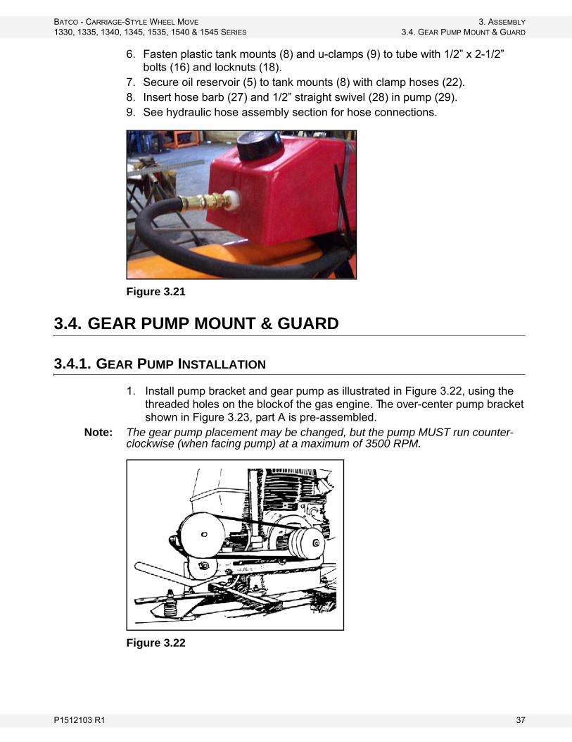
6. Fasten plastic tank mounts (8) and u-clamps (9) to tube with 1/2” x 2-1/2” bolts (16) and locknuts (18).
7. Secure oil reservoir (5) to tank mounts (8) with clamp hoses (22).8. Insert hose barb (27) and 1/2” straight swivel (28) in pump (29).9. See hydraulic hose assembly section for hose connections.
Figure 3.21
3.4. GEAR PUMP MOUNT & GUARD
3.4.1. GEAR PUMP INSTALLATION
1. Install pump bracket and gear pump as illustrated in Figure 3.22, using the threaded holes on the block of the gas engine. The over-center pump bracket shown in Figure 3.23, part A is pre-assembled.
Note: The gear pump placement may be changed, but the pump MUST run counter-clockwise (when facing pump) at a maximum of 3500 RPM.
Figure 3.22
P1512103 R1 37

3. ASSEMBLY BATCO - CARRIAGE-STYLE WHEEL MOVE3.5. VALVE 1330, 1335, 1340, 1345, 1535, 1540 & 1545 SERIES
Figure 3.23
3.4.2. PUMP GUARD INSTALLATION
1. Bolt the pump guard bracket to the over-center pump bracket as shown in Figure 3.23, part B. The bracket should be installed at the pump end of the long, adjustable slot, through the middle of the over-center bracket (Figure 3.23, part A).
2. Place two washers between the pump guard bracket and the over-center bracket, so that the angle of the bracket may be adjusted to the belt.
3. Attach the pump guard to the pump guard bracket (Figure 3.23, part B). Align the pump guard with the belt that runs between the pump and the engine. The pump guard bracket may need to be adjusted to achieve the appropriate angle. Ensure that there is adequate clearance between the belt and the pump guard, with belt engaged and disengaged.
3.5. VALVE
3.5.1. RAM SPEED ADJUSTMENT
1. Adjust ram speed is regulated at the control panel. The adjustable stroke limiter screws and lock nuts set the speed of the ram travel individually in each direction.
2. Adjust the stroke limiter screws and lock nuts until the desired rate of travel is achieved.
3. T urning the screws inward results in a slower speed
4. Turning the screws outward results in a faster speed
Figure 3.24
38 P1512103 R1

BATCO - CARRIAGE-STYLE WHEEL MOVE 3. ASSEMBLY1330, 1335, 1340, 1345, 1535, 1540 & 1545 SERIES 3.5. VALVE
Note: All spools are of a special metering design which allows more precision in maneuverability.
Figure 3.25
Figure 3.26
Table 3.6 Item Description Part No. Qty
A 2503 WINCH P020707001 1B SAFETY BRACKET P020707003 1C MOTOR COUPLER P020700001 1
D ORBIT MOTOR P021011312/P029901001PRP 1
E MOTOR BRACKET P020707002 1F WINCH VALVE P020700008 1G END CAP P021600023 2H END CAP W/ BOLT P021600024 1J CAP W/ SPRING P021600008 3K THREE-SPOOL VALVE, COMPLETE (NO FITTINGS) P021600006 1
L LEVER PIVOT BOX W/ LEVER ARM, LEVER PIN, AND RUBBER BOOT P021600026 1
M CONTROL LEVERS FOR SPOOL VALVE P021600007 2N BOOT, 3-SPOOL LEVER P021600026B 3
P1512103 R1 39

3. ASSEMBLY BATCO - CARRIAGE-STYLE WHEEL MOVE3.6. WINCH 1330, 1335, 1340, 1345, 1535, 1540 & 1545 SERIES
3.6. WINCH
3.6.1. WINCH ASSEMBLY
1. Remove the hand winch and bolt on the hydraulic winch.
2. Angle the winch so it lines up with the cable wrapping around the track roller.
3. T ighten all nuts.4. Position so that the cable pulls away
from the drum and away from the winch body.
3.6.2. WINCH ALIGNMENT
1. Check the alignment of the winch by watching the cable wrapping on the drum as the conveyor is raised. Proper alignment is achieved when the cable indexes, filling each row on the drum evenly and not piling up against one side.
2. Lower the conveyor fully if the cable does not index properly until there is slack in the cable.
3. Loosen the nuts on the u-clamps, adjust the winch, retighten nuts and retest. For example, if the cable is piling up to the right hand side of the drum, move the U-bolt end of the winch to the left.
WARNING
The winch must ratchet when drawing the cable and raising the conveyor. Serious damage to equipment or injury to the operator could occur if the winch does not ratchet.
Figure 3.27
40 P1512103 R1

BATCO - CARRIAGE-STYLE WHEEL MOVE 3. ASSEMBLY1330, 1335, 1340, 1345, 1535, 1540 & 1545 SERIES 3.6. WINCH
3.6.3. OPERATION AND ADJUSTMENT OF WINCH VALVE
Important: The winch valve has a pressure kickout built into it. This kickout is designed to protect the operator and equipment in cases where the roller comes to the end stop of the track and the operator tries to go higher. In these instances the kickout will automatically internally bypass and will not reset until the valve is released. Without this protection, the hydraulic motor has the power to twist off winch shaft, allowing the cable to unwind and causing the conveyor to drop.
1. Adjust the kick-out valve to obtain a higher or lower pressure setting.2. Loosen the locknut on the outside body of the kickout (Figure 3.28). The
kickout is screwed into the side of the winch valve block. After loosening the lock nut, decrease the pressure by turning out the stud. Increase the pressure by turning in the stud.
3. If the valve repeatedly kicks out when operating the winch, loosen the lock nut and turn in the stud – NO MORE THAN 1/8 OF A TURN!
Note: Initial winch speed adjusted in shop. Cold temperatures may slow winch down.
Figure 3.28 Hydraulic MotorTable 3.7
Item Description Part No. Qty1 HYDRAULIC WINCH KIT W/ VALVE P020707000 12 SWIVEL, 1/2” M X 3/8” F, STRAIGHT P0821124 6
CAUTION
Do not adjust more than 1/8 of a turn at a time. Serious damage could result.
P1512103 R1 41

3. ASSEMBLY BATCO - CARRIAGE-STYLE WHEEL MOVE3.7. WHEEL MOVE DRIVE SYSTEM 1330, 1335, 1340, 1345, 1535, 1540 & 1545 SERIES
3.7. WHEEL MOVE DRIVE SYSTEM
Note: Refer to Tables 3.8 and 3.9 for the quantity of each component used, and Figures 3.29 to 3.31 for the assembly of the wheel move drive system.
Note: Repeat the following section for each of the right and left side wheel move motor assemblies. The right and left sides are mirror images.
1. Fasten motor arm to wheel move axle tab (on the axle) using a 1/2” x 2” bolt and locknut.
2. Connect 1/2 swivels to the hydraulic motor.3. Insert pinion gear on hydraulic motor and lock with set screw.4. Mount the hydraulic motor on the motor arm with 3/8” x 2” bolts and 3/8” lock
washers (not shown).5. Noting the orientation in Figures 3.30 and 3.31, install the wheel move spring
and overcenter handle to the axle tab with 1/2” x 2” bolts, locknuts, and flat washers.
6. Fix the overcenter link to the wheel move handle with a 1/2” locknut, then attach to the spring.
7. Connect the overcenter link to the motor arm with a 1-1/2” locknut.8. The cushion block installation is covered in the hydraulic hose assembly
section. See “Hydraulic Hose Assembly” on page 48 for details.
Figure 3.29 Table 3.8
Item Description Part No. Qty1 CUSHION BLOCK P020200350 12 WHEEL MOVE MOTOR ASSY - 13 WHEEL MOVE MOTOR ASSY - 1
42 P1512103 R1

BATCO - CARRIAGE-STYLE WHEEL MOVE 3. ASSEMBLY1330, 1335, 1340, 1345, 1535, 1540 & 1545 SERIES 3.7. WHEEL MOVE DRIVE SYSTEM
GEAR ALIGNMENT - DEPTH
The pinion gear should sit in the ring gear to ensure maximum contact between teeth. If the pinion gear does not mesh properly, adjust the overcenter handle.
• If the handle will not lock in the overcenter position, loosen the flange nuts and slide the slotted handle away from the tire.
• If the pinion gear does not mesh fully with the ring gear, loosen the flange nuts and slide the slotted handle toward the tire.
Figure 3.30
Table 3.9 Item Description Part No. Qty
1 WHEEL-MOVE OVERCENTER HANDLE P020200007 12 OVER-CENTER LINK SP WHEEL MOTOR P020200008 13 WHEEL MOVE SPRING P020200009 14 PINION GEAR P020200333 15 RING GEAR P020200334 16 MOTOR ARM P020200338A 17 BOLT 1/2” X 2” GR8 P0118016 18 BOLT 1/2” X 2” GR8 P0118016 19 BOLT HEX 3/8” X 2” P0115050 4
10 NUT NYLOCK 1/2” P0134008 311 NUT FLANGE 1/2” P0134108 212 FLAT WASHER 1/2 PLATED USS P0151029 313 SWIVEL 90 1/2” M X 3/8” F P0820013 214 HYD MOTOR, 5.9 H-C/HOLE P0841012 115 WHEEL-MOVE AXLE TAB 3” P020200340A 1
P1512103 R1 43

3. ASSEMBLY BATCO - CARRIAGE-STYLE WHEEL MOVE3.8. GEAR DRIVE 1330, 1335, 1340, 1345, 1535, 1540 & 1545 SERIES
Figure 3.31
3.8. GEAR DRIVE
3.8.1. GEAR DRIVE INSTALLATION
1. Press ring gear into rim. Use a hammer to be sure the ring gear seats evenly into the rim. Tighten the 4 set screws in rotation to lock gear evenly into place.
2. Hit the ring gear with a hammer again at each set screw and retighten in rotation.
3. Use a hammer after tightening and punch to deep set the screws by giving a blow beside each screw. Then, retighten set screws.
4. W eld ring into position.Figure 3.32
44 P1512103 R1

BATCO - CARRIAGE-STYLE WHEEL MOVE 3. ASSEMBLY1330, 1335, 1340, 1345, 1535, 1540 & 1545 SERIES 3.8. GEAR DRIVE
Figure 3.33
3.8.2. OVER-CENTER DRIVE INSTALLATION
Once the wheel is bolted to the hub the over-center drive assembly can be installed as follows:
1. Position the axle cap of the over-center drive assembly squarely on the axle tube as shown in Figure 3.32.
2. With the pinion gear flush with the ring gear, as shown in Figure 3.34, weld the axle cap to the axle tube.
Figure 3.34
P1512103 R1 45

3. ASSEMBLY BATCO - CARRIAGE-STYLE WHEEL MOVE3.8. GEAR DRIVE 1330, 1335, 1340, 1345, 1535, 1540 & 1545 SERIES
3.8.3. PINION GEAR ADJUSTMENT
Figure 3.35
GEAR DEPTH ALIGNMENT
Refer to Figure 3.35. The pinion gear should mesh with the ring gear to provide maximum tooth contact. If the pinion gear meshes incorrectly, adjust the handle slot bolt (which bolts to the drive mount clamp) so full meshing of pinion gear is achieved when handle is in over-center position.
GEAR TEETH BINDING
The handle will not “lock” into the over-center position. Loosen the slot bolt nuts and slide the handle away from the tire.
INSUFFICIENT MESHING
The pinion gear will barely mesh with the ring gear. Loosen the slot bolt jam nuts and slide the handle towards the tire until the pinion gear teeth mesh with the ring gear teeth without binding.
46 P1512103 R1

BATCO - CARRIAGE-STYLE WHEEL MOVE 3. ASSEMBLY1330, 1335, 1340, 1345, 1535, 1540 & 1545 SERIES 3.8. GEAR DRIVE
3.8.4. CUSHION VALVE ASSEMBLY & OPERATION
ASSEMBLY
1. Connect hoses as shown in Figure 3.36.
Important: Before disassembling the hoses, relieve oil pressure as the oil may be hot enough to cause serious burns.
Figure 3.36
OPERATION
To control the speed of the wheel move, the adjustable needle valve can be:
• screwed in for full speed• screwed out for a slower speed
CAUTION
Do not overtighten hoses. Over tightening hoses can crack the motor body or cause the fittings to leak and will void the motor warranty.
CAUTION
The conveyor must move in the direction that the handle is moved.
Serious operator injury could occur if the transport unit and hydraulic hoses are not assembled correctly.
If necessary, disconnect the hoses, and re-assemble.
P1512103 R1 47

3. ASSEMBLY BATCO - CARRIAGE-STYLE WHEEL MOVE3.9. HYDRAULIC HOSE ASSEMBLY 1330, 1335, 1340, 1345, 1535, 1540 & 1545 SERIES
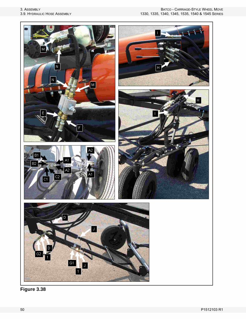
3.9. HYDRAULIC HOSE ASSEMBLY
Note: Refer to Table 3.10 for the quantity of each component used and Figures 3.37 and 3.38 for hydraulic hose assembly.
Figure 3.37
1. Place cushion block approximately as shown in Figure 3.38 and attach two 3/8” swivels to the front.
2. Att ach hydraulic fittings (1) to the wheel move hydraulic cylinders.3. Connect each hose as labeled in Figure 3.37 and Table 3.10. For example,
connect hydraulic hose A1 in the table to each of the locations marked A1 in Figures 3.37 and 3.38.
4. Install hose clamps as required along axle, axle arms, etc. Use Figure 3.38 as a guide.
Note: The 3/4” hose (L) installs from tank to pump with two hose clamps listed in the gas wet kit assembly.
48 P1512103 R1

BATCO - CARRIAGE-STYLE WHEEL MOVE 3. ASSEMBLY1330, 1335, 1340, 1345, 1535, 1540 & 1545 SERIES 3.9. HYDRAULIC HOSE ASSEMBLY
Tab
le 3
.10
Item
Des
crip
tio
nF
itti
ng
Fit
tin
g
Hyd
rau
lic H
ose
Len
gth
s b
y C
on
veyo
r Ty
pe
and
Siz
e
Qty
1300
0164
35 S
TD
/FL
HG
M P
/P
1600
0163
145
FL
ST
R D
D
1300
0166
45 F
LS
TR
HG
M
1300
0166
45 S
TD
ST
R H
GM
1300
0166
145
FL
ST
R P
/P
1300
0167
45 S
TD
ST
R H
GM
A1,
A2
3/8”
HO
SE
3/8
MP
T3/
8 M
PT
1’9”
1’8”
1’8”
1’9”
1’9”
1’8”
2B
1, B
23/
8” H
OS
E3/
8 M
PT
3/8
MP
T5’
6”5’
5’5’
6”5’
6”5’
2C
1, C
23/
8” H
OS
E3/
8 JI
C3/
8 M
PT
9’6”
12’6
”12
’6”
9’6”
9’6”
12’6
”2
D3/
8” H
OS
E1/
2 M
PT
1/2
MP
T2’
6”2’
6”2’
6”2’
6”2’
6”2’
6”1
E3/
8” H
OS
E1/
2 M
PT
3/8
JIC
7’6”
30’
30’
7’6”
7’6”
30’
1F
3/8”
HO
SE
1/2
MP
T3/
8 JI
C7’
6”30
’30
’7’
6”7’
6”30
’1
G1
3/8”
HO
SE
3/8
MP
T3/
8 JI
C4’
25’6
”25
’6”
4’4’
25’6
”1
G2
3/8”
HO
SE
3/8
MP
T3/
8 JI
C3’
6”25
’6”
25’6
”3’
6”3’
6”25
’6”
1H
1/2”
HO
SE
1/2
MP
T1/
2 M
PT
12’
30’6
”30
’6”
12’
12’
30’6
”1
I1/
2” H
OS
E1/
2 M
PT
1/2
MP
T9’
6”33
’6”
33’6
”9’
6”9’
6”33
’6”
1J
3/8”
HO
SE
3/8
MP
T3/
8 M
PT
2’6”
2’6”
2’6”
2’6”
2’6”
2’6”
1L
3/4”
HO
SE
--
10’
2’10
’10
’10
’10
’1
M3/
8” H
OS
E1/
2 M
PT
1/2
MP
T1’
6”1’
6”1’
6”1’
6”1’
6”1’
6”1
N3/
8” H
OS
E1/
2 M
PT
1/2
MP
T1’
6”1’
6”1’
6”1’
6”1’
6”1’
6”1
1TE
E 3
/8” (
P02
9900
791)
- -
- -
- -
--
22
SW
IVE
L 3/
8” S
TRA
IGH
T-
--
--
--
-2
P1512103 R1 49
3. ASSEMBLY BATCO - CARRIAGE-STYLE WHEEL MOVE3.9. HYDRAULIC HOSE ASSEMBLY 1330, 1335, 1340, 1345, 1535, 1540 & 1545 SERIES
Figure 3.38
50 P1512103 R1

BATCO - CARRIAGE-STYLE WHEEL MOVE 3. ASSEMBLY1330, 1335, 1340, 1345, 1535, 1540 & 1545 SERIES 3.10. WIRING - DIRECT DRIVE WHEEL MOVES
3.10. WIRING - DIRECT DRIVE WHEEL MOVES
Refer to Table 3.11 for the quantity of each component used and Figures 3.39 to 3.46 for the wiring assembly.
Note: Cover wire with shrinkable tube.
Figure 3.39 Onan/Linamar Figure 3.40 Honda
Figure 3.41
Table 3.11 Item Description Qty Item Description Qty
1 STARTER PALTE CLAMP 1 14 14 GA WIRE 12 BRACKET 1 15 14 GA WIRE 13 WHEATHEART SWITCH 1 16 14 GA WIRE 14 FUSE 20A 1 17 14 GA WIRE 15 SHRINKABLE TUBE 1 18 14 GA WIRE 16 PLASTIC TIE STRAPS 10 19 14 GA WIRE 17 BATTERY 1 20 14 GA WIRE 18 BATTERY CABLE (POS) 1 21 14 GA WIRE 19 BATTERY CABLE (NEG) 1 A, B 14 GA WIRE 1
10 BATTERY CABLE (POS) 1 C, D 14 GA WIRE 111 BATTERY CABLE (NEG) 1 23 WHEATHEART SWITCH BRACKET 112 14 GA WIRE 1 24 BOLT HEX 5/16” X 1” 113 14 GA WIRE 1 25 NUT NYLOCK 5/16” 1
P1512103 R1 51

3. ASSEMBLY BATCO - CARRIAGE-STYLE WHEEL MOVE3.10. WIRING - DIRECT DRIVE WHEEL MOVES 1330, 1335, 1340, 1345, 1535, 1540 & 1545 SERIES
3.10.1. ONAN/LINAMAR ENGINE
Refer to Figure 3.39 for the appropriate wiring diagram.
1. Remove starter plate from engine and construct a starter plate clamp similar to one shown in Figure 3.42 using one supplied 2” u-clamp. Moving the starter plate allows easy access to controls when conveyor is elevated.
Figure 3.42
2. Attach starter plate clamp to tube with a 2” u-clamp and 1/2” x 2-1/2” grade 8 bolts and locknuts.
3. Wire a 20A fuse and connector (Figure 3.43) to switch middle port and extra port at key (Figure 3.39).
Figure 3.43
4. Connect wire from one of the two remaining ports on switch to the electric clutch.
PLUG IN
3
52 P1512103 R1

BATCO - CARRIAGE-STYLE WHEEL MOVE 3. ASSEMBLY1330, 1335, 1340, 1345, 1535, 1540 & 1545 SERIES 3.10. WIRING - DIRECT DRIVE WHEEL MOVES
5. Attach a wire from the electric clutch to the motor ground (Figure 3.44).
Figure 3.44
6. Add 6-1/2 feet wire to the wire connecting the motor to the key (Figure 3.41). Mark each wire A,B,C,D in two spots, cut, and connect appropriate gauge of extension wire with butt connectors. For example, connect A to A with 6-1/2 feet of extension wire.
Note: Two wires are 12 ga and two are 14 ga. Ensure extra wire used is the same gauge as its mate.
7. Plug extended wire into connectors on key and motor as illustrated in Figures 3.45 and 3.42.
Figure 3.45
8. Install wires in switch as noted in Figure 3.39.9. Connect switch and bracket to starter plates with 5/16” x 1” size bolt and
locknut.10. Connect battery cables from motor to battery, noting the orientation in Figure
3.44.
8 7 9GROUND
PLUG IN
P1512103 R1 53

3. ASSEMBLY BATCO - CARRIAGE-STYLE WHEEL MOVE3.10. WIRING - DIRECT DRIVE WHEEL MOVES 1330, 1335, 1340, 1345, 1535, 1540 & 1545 SERIES
11. Secure wires with tie straps; see Figure 3.46.
Figure 3.46
12. If unit does not start check/try:a. all wires are securely connected.b. reversing connections on electric clutch.c. battery terminals caps are removed.
3.10.2. HONDA ENGINE
Refer to Figure 3.40 for the appropriate wiring diagram.
1. Remove starter plate from engine and construct starter plate clamp similar to one shown in Figure 3.42 using one supplied 2” u-clamp. Moving the starter plate allows easy access to controls when conveyor is elevated.
2. Attach starter plate clamp to tube with a 2” u-clamp and 1/2” x 2-1/2” grade 8 bolts and locknuts.
3. Wire a 20A fuse and connector to battery positive terminal, and other end to switch (Figure 3.40).
4. Connect wire from one of the two remaining ports on switch to the electric clutch.
5. Attach a wire from the electric clutch to the battery negative terminal.6. Add 6-1/2 feet wire to the wire connecting the motor to the key (Figure 3.41).
Mark each wire A,B,C,D in two spots, cut, and connect appropriate gauge of extension wire with butt connectors. For example, connect A to A with 6-1/2 feet of extension wire.
Note: Two wires are 12 ga and two are 14 ga. Ensure extra wire used is the same gauge as its mate.
7. Plug extended wire into connectors on key and motor as illustrated in Figure 3.40.
8. Install wires in switch as noted in Figure 3.40.9. Connect switch and bracket to starter plates with 5/16” x 1 “bolt and locknut.10. Connect battery cables from motor to battery, noting the orientation in Figure
3.44.11. Secure wires with tie straps; see Figure 3.46.
54 P1512103 R1

BATCO - CARRIAGE-STYLE WHEEL MOVE 4. TRANSPORT & PLACEMENT1330, 1335, 1340, 1345, 1535, 1540 & 1545 SERIES 4.1. TRANSPORT PROCEDURE
tion r
4. Transport & Placement
4.1. TRANSPORT PROCEDURE
Note: Use only a tractor or towing vehicle of adequate power and capacity to transport the machine.
Follow all safety precautions when transporting the conveyor and follow this procedure when placing the unit into its transport position:
1. Clear the area of bystanders, especially children, before starting.2. Be sure there is enough clearance from overhead obstructions, power lines,
and other equipment to move the machine into its transport position.3. Attach the conveyor intake to the towing vehicle with a minimum 3/4”
diameter pin with retainer clip and safety chain.4. Fully raise the wheel move assembly by retracting the hydraulic cylinder.5. Before transporting, disengage the over-center handle at each wheel by
pulling up on the handle (Figure 4.1).
Figure 4.1
6. For transportation on public roadways, secure the wheel move frame to the conveyor tube to prevent it from accidentally dropping. This can be done by attaching a strap/chain/cable from one side of the mover frame up over the top of the conveyor tube and back onto the other side of the conveyor frame.
WARNING Before continuing, ensure you have read and understand the relevant informain the safety section. Safety information is provided to help prevent serious injury, death, oproperty damage.
NOTICE
Ensure that the over-center bolts are tight enough to prevent the handle from engaging. If they are not tight enough, damage to the gears and motor will result.
Handle down = engaged Handle up
= disengaged
P1512103 R1 55

4. TRANSPORT & PLACEMENT BATCO - CARRIAGE-STYLE WHEEL MOVE4.2. PLACEMENT PROCEDURE 1330, 1335, 1340, 1345, 1535, 1540 & 1545 SERIES
7. Make sure the SMV (Slow Moving Vehicle) emblem and all the lights and reflectors that are required by the local highway and transport authorities are in place, are clean, and can be seen clearly by all overtaking and oncoming traffic.
8. Consult with local authorities regarding transport on public roads. Obey all applicable laws and regulations.
9. Pin castors into lock position so that walking beams do not tip.
4.2. PLACEMENT PROCEDURE
Follow this procedure when placing the machine into its working position:
1. Be sure there is enough clearance from overhead obstructions, power lines, or other equipment to move the machine into its working position.
2. Position the machine in the desired area. For operation instruction, see Section 5.3.
WHEN PLACING UNDER HOPPER BOTTOM BINS:
1. The conveyor hopper is centered between the hopper bin vertical legs.2. Conveyor’s engine will not make contact with the hopper cone when in its
final position.3. Collapse the cloth hopper until it is positioned under the bin.4. Raise conveyor spout to desired height and close ball valve.
WARNING
Use extreme care and use minimum ground speed when operating or transporting on hillsides, over rough ground, or near ditches or fences.
DANGER
Stay away from overhead power lines. Arcing and possible electrocution can occur without direct contact.Consult local utility companies before operating machine near power lines.
NOTICE
Ensure that gravel is not jammed against the belt under the hopper. It is possible that the rocks may cut or tear the belt. It is good practice to remove all foreign material from the belt path to ensure no damage to the belt occurs.
56 P1512103 R1

BATCO - CARRIAGE-STYLE WHEEL MOVE 4. TRANSPORT & PLACEMENT1330, 1335, 1340, 1345, 1535, 1540 & 1545 SERIES 4.2. PLACEMENT PROCEDURE
BEFORE FILLING THE BINS:
1. Ensure that the bin lid is open.3. Ensure that the engine is at idle. A slower mover speed allows for easier
positioning.4. Position the conveyor spout over bin and it is in the bin’s fill hole.5. Lower the wheel move frame until hopper is on the ground.6. Check spout and lower further into the bin’s fill hole if necessary. 7. Ensure that the plastic hood is not resting on the bin’s fill hole and ensure
that the conveyor is not making contact with the bin roof. Raise the spout if necessary or reposition the conveyor.
8. Ensure the ball valve is closed.9. Start up the conveyor and engage the belt drive to ensure everything is
positioned correctly before unloading grain.
P1512103 R1 57

4. TRANSPORT & PLACEMENT BATCO - CARRIAGE-STYLE WHEEL MOVE4.2. PLACEMENT PROCEDURE 1330, 1335, 1340, 1345, 1535, 1540 & 1545 SERIES
58 P1512103 R1

BATCO - CARRIAGE-STYLE WHEEL MOVE 5. OPERATION1330, 1335, 1340, 1345, 1535, 1540 & 1545 SERIES 5.1. PRE-OPERATION CHECKLIST
tion r
5. Operation
5.1. PRE-OPERATION CHECKLIST
Efficient and safe operation of the equipment requires that each operator read and understand the operating procedures and all related safety precautions outlined in this manual. A pre-operation checklist is provided for the operator. It is important that this checklist is followed for both personal safety, and maintaining the mechanical condition of the conveyor.
Before initially operating the conveyor, and each time thereafter, the following areas should be checked:
• Service the machine as outlined in the schedule in the Maintenance sec-tion.
• Check that all guards are installed, secured, and functioning as intended. Do not operate with missing or damaged guards.
• Inspect all hydraulic lines, hoses, fittings, and couplers for tightness. Use a clean cloth to wipe any accumulated dirt from the couplers before con-necting to the hydraulic system of the tractor.
• Visually inspect the unit for damage to components. Replace or repair any damaged or questionable parts.
• Check hydraulic system oil level.• Consult local utility companies to identify the location of overhead power
lines. • Check work site. Clean up working area to prevent slipping or tripping.• Machine must be securely attached to the towing vehicle or tractor.
5.2. START-UP & BREAK-IN
Although there are no operational restrictions on the conveyor when used for the first time, it is recommended that the following mechanical items be checked.
BEFORE STARTING:
1. Read the conveyor operation manual.
WARNING Before continuing, ensure you have read and understand the relevant informain the safety section. Safety information is provided to help prevent serious injury, death, oproperty damage.
WARNING
Shut off and remove key or lock out power source before inspecting or servicing the machine.
P1512103 R1 59

5. OPERATION BATCO - CARRIAGE-STYLE WHEEL MOVE5.3. OPERATING PROCEDURE 1330, 1335, 1340, 1345, 1535, 1540 & 1545 SERIES
DURING THE FIRST FEW MINUTES:
1. Check belt alignment to ensure preset alignment does not vary under loaded conditions. See conveyor operation manual for correct alignment conditions.
2. Some air may still be trapped in the hydraulic system; slowly activate all hydraulic control valves to ensure that all the air is out of the system.
AFTER TRANSPORTING OR OPERATING FOR 1/2 HOUR:
1. Retorque all wheel bolts, fasteners, and hardware. 2. Check that all safety decals are installed and legible. Apply new decals if
required.3. Check that all guards are installed and are working as intended.
AFTER OPERATING FOR 3 HOURS:
1. Change oil in the system for best results.
AFTER OPERATING FOR 5 AND 10 HOURS:
1. Retorque all wheel bolts, fasteners, and hardware.2. Check that safety decals are intact and legible. Install new ones if required.3. Check that all guards are installed and working properly.
4. Check all hydraulic hoses and fittings for leaks. Tighten fittings where required. Replace worn or damaged hoses.
Continue with normal servicing and maintenance schedule as defined in the Grain Conveyor Operation manual.
5.3. OPERATING PROCEDURE
Important: Ensure the over-center handle at each wheel is fully engaged by pushing down on the handle at each wheel and checking that the gears fully mesh. See Section “Over-Center Drive Installation” on page 45 for adjustment (if necessary).
1. With the engine at idle, use the hydraulic controls to fully lower the conveyor with the scissor lift lever on the valve before moving the conveyor into position.
2. Raise the conveyor intake end off the ground using the hydraulic ram control lever on the valve.
3. Move the conveyor into place by moving the wheel move control forward or backward to control the direction of travel. Steering is accomplished by grasping the handle bar and turning it. Steering is easier if the conveyor is in motion.
4. When unloading a bin, aim the conveyor intake into the bottom of the center of the bin. Use the scissor lift lever and hydraulic ram control lever to help position the conveyor.
5. When loading a bin, use the scissor lift to raise the conveyor to the desired height. Use the hydraulic ram control to raise the intake of the conveyor off the ground as the conveyor is winched up. Turn the wheel move control to change the direction of travel. Leave extra clearance for making wide turns.
60 P1512103 R1

BATCO - CARRIAGE-STYLE WHEEL MOVE 5. OPERATION1330, 1335, 1340, 1345, 1535, 1540 & 1545 SERIES 5.4. WEATHER
Note: Refer to “Cushion Valve Assembly & Operation” on page 47 for cushion valve adjustment and “Ram Speed Adjustment” on page 38 for adjustment of the ram speed.
5.4. WEATHER
Important: When running the conveyor in colder temperatures, you should always disengage the pump when starting the motor cold. This will put less pressure on the starter and allow the motor to turn over easier, helping it to start..
CAUTION
Do not attempt to move the conveyor on uneven or hilly terrain. The mover will not perform well under these conditions and could damage the machine or injure the operator.
NOTICE
The hydraulic oil should be checked periodically to ensure that the levels are correct. Running the machine on low oil will overheat the system causing components to break down and eventually fail.
CAUTION
Do not attempt to move the conveyor on uneven or hilly terrain. The mover will not perform well under these conditions and could damage the machine or injure the operator.
CAUTION
The pump should be disengaged to take the strain off the belt, and the wheel move motors should also be disengaged to take the strain off of the springs.
P1512103 R1 61

5. OPERATION BATCO - CARRIAGE-STYLE WHEEL MOVE5.4. WEATHER 1330, 1335, 1340, 1345, 1535, 1540 & 1545 SERIES
62 P1512103 R1

BATCO - CARRIAGE-STYLE WHEEL MOVE 6. MAINTENANCE AND STORAGE1330, 1335, 1340, 1345, 1535, 1540 & 1545 SERIES 6.1. MAINTENANCE PROCEDURE
tion r
6. Maintenance and Storage
6.1. MAINTENANCE PROCEDURE
Before performing any maintenance on this unit, shut off and remove key or lock out the power source.
1. Periodically check for wear and proper meshing of the ring gear and pinion.2. Change oil annually to remove any accumulation of dirt or condensation in
the system. Replace with Type A automatic Transmission oil. Do not over-fill reservoir. Leave 1/2 quart (0.47 L) space to allow for level fluctuation.
3. Inspect hoses and fittings. Replace as required.4. Inspect ring and pinion gears. Replace if worn.
6.2. STORAGE PROCEDURES
For long, trouble-free life, prepare unit for storage after the season’s use.
• Lock out all power.• Store the machine on a level surface, free of debris, and in an area away
from human activity. Store in a dry place, or use a tightly secured tarp to protect the equipment from the weather.
• Place unit in transport position.• Remove all residual material and clean the machine thoroughly. • Inspect the unit at stress points for cracks.• Repair or replace any worn or damaged components to prevent any
unnecessary downtime at the start of the next season.• Touch up paint nicks and scratches to prevent rusting. • Check hydraulic fittings, hoses, lines, couplers, and valves. Tighten any
loose fittings. Replace any hose that is badly cut, nicked, abraded, or is separating from the crimped end of the fitting. Secure the hoses to the machine.
• Inspect and tighten all fasteners; replace fasteners if required. • Check tire inflation.
• Retract all cylinders or grease exposed shafts.• Inspect hydraulic cylinders for leaks; replace seals if necessary.
WARNING Before continuing, ensure you have read and understand the relevant informain the safety section. Safety information is provided to help prevent serious injury, death, oproperty damage.
P1512103 R1 63

6. MAINTENANCE AND STORAGE BATCO - CARRIAGE-STYLE WHEEL MOVE6.2. STORAGE PROCEDURES 1330, 1335, 1340, 1345, 1535, 1540 & 1545 SERIES
64 P1512103 R1

BATCO - CARRIAGE-STYLE WHEEL MOVE 7. TROUBLESHOOTING1330, 1335, 1340, 1345, 1535, 1540 & 1545 SERIES
7. TroubleshootingThe Batco Carriage-Style Wheel Move is a simple and reliable system that requires minimal maintenance. In the following section, we have listed many of the problems, causes, and solutions to the problems that you may encounter.
If you encounter a problem that is difficult to solve even after reading through this troubleshooting section, please call your local Batco dealer or distributor. Before you call, please have this manual and the serial number from your machine ready.
Table 7.1
Problem Cause Solution
Intake does not lift.
• blockage in pressure line • locate blockage and remove• valve malfunctioning • adjust stroke limiter screws
or replace/repair valve.• cylinder (s) bypassing inter-
nally• replace cylinder seals
Conveyor lifts but drops slightly before lifting.
• worn valve due to oil contam-ination
• replace valve, check and replace oil if dirty
Discharge does not lift.
• cable broken • replace cable• blockage in pressure line • locate blockage and remove• relief valve malfunctioning • fine tune adjustment stud
(see “Winch” on page 40)• coupler stripped/broken • replace coupler• worn valve due to oil contam-
ination• replace valve• check and replace oil if dirty
Intake lift cylinders over-center and carriage can-not come down.
• bracket has slid up tube • loosen bracket and reposi-tion (see Appendix for bracket locations)
• conveyor parked on steep slope
• move to level ground, undo pins at hydraulic lift cylin-ders, lower cylinders, and re-attach cylinders with pins
Conveyor will not move.
• block in front of tire • remove block• blockage in pressure line • locate and remove• relief valve (cushion block)
malfunctioning• adjust or replace if required
(see “Gear Drive” on page 44)
• motor worn/damaged • check and replace oil if dirty• replace hydraulic motor
• pinion gear not making con-tact
• adjust positioning (see “Gear Drive” on page 44)
• pinion gear stripped • replace gear (“Gear Drive” on page 44)
P1512103 R1 65

7. TROUBLESHOOTING BATCO - CARRIAGE-STYLE WHEEL MOVE 1330, 1335, 1340, 1345, 1535, 1540 & 1545 SERIES
No working functions.
• loose belt on pump • tighten belt• key broken • replace key• pump not working • repair/replace pump• engine not working • consult engine operation
manual• call dealer/distributor
Pump makes noise.
• air in hydraulic system • check level, add if required• low on fluid • check level, add if required• loose suction line • tighten suction line at
hydraulic tank
Pump does not run.
• blockage in pressure line • locate blockage and remove• belt loose/broken • tighten/replace belt• pump seized (oil contamina-
tion)• replace hydraulic oil /
replace pump
Table 7.1
Problem Cause Solution
66 P1512103 R1

BATCO - CARRIAGE-STYLE WHEEL MOVE 8. APPENDIX1330, 1335, 1340, 1345, 1535, 1540 & 1545 SERIES 8.1. BRACKET LOCATIONS
8. Appendix8.1. BRACKET LOCATIONS
Bracket locations on the Batco Carriage-Style Wheel Move are shown in Figure 8.1 and Table 8.1 below. The dimensions are measured from the flange of the field loader hopper to the far edge of the bracket.
Figure 8.1 Bracket Location Dimensions
Table 8.1 Bracket Location Dimensions According to Model and Type
Bracket Location1335 FL 1345 FL
HGMa
a. HGM - Hanging Gas Mount
DDb
b. Direct Drive
HGM DD
A WM Suspension Bracket 1’10-1/2” 1’10-1/2” 6’ 6’B Ring Bottom w/ Cylinder Mount 3’6” 3’6” 3’6” 3’6”C Plastic Tank Mount - 4’7” - 10’5”D Plastic Tank Mount - 5’10” - 11’8”E S-Drive 10’2” 10’2” 15’3” 15’3”F Gas/Hydraulic Tank Side Mount 7’4” 10’7” 12’5” 17’9”G Gas/Hydraulic Tank Side Mount 8’9” 11’10” 13’10” 18’H Winch Bracket 13’4” 13’4” 19’ 19’
PUSH/PULL MOVERS ONLY
P1512103 R1 67

8. APPENDIX BATCO - CARRIAGE-STYLE WHEEL MOVE8.2. BOLT TORQUE 1330, 1335, 1340, 1345, 1535, 1540 & 1545 SERIES
ne
8
.8
2
3
5
3
4
4
3
9
0
1
8.2. BOLT TORQUE
Table 8.2 gives correct torque values for various hardware. Tighten all bolts to the torque specified, unless otherwise noted. Check tightness periodically, using Table 8.2 as a guide. Replace hardware with the same strength bolt.
Table 8.2 Recommended Bolt Torque
SizeDry or
Lubricated
Threads per inch (Course/
Fine)
Recommended Torque
Area of Bolt Grade 2 Grade 5 Grade 8 8.8S/S
Coarse Fine Coarse Fine Coarse Fine Coarse Fine Coarse Fi
1/4 Dry 20/28 0.0318 0.0364 5.5 6.3 8 10 12 14 6.3 7.Lubricated 6.3 4.7 6.3 7.2 9 10 - -
5/16 Dry 18/24 0.0524 0.058 11 12 17 19 24 27 11 11Lubricated 8 9 13 14 18 20 - -
3/8 Dry 16/24 0.0775 0.0878 20 23 30 35 45 50 20 2Lubricated 15 17 23 25 35 35 - -
7/16 Dry 14/20 0.1063 0.1187 32 36 50 55 70 80 31 3Lubricated 24 27 35 40 50 80 - -
1/2 Dry 13/20 0.1419 0.1599 50 55 75 85 110 120 43 4Lubricated 35 40 55 65 80 90 - -
9/16 Dry 12/18 0.182 0.203 70 80 110 120 150 170 57 6Lubricated 55 60 80 90 110 130 - -
5/8 Dry 11/18 0.226 0.256 100 110 150 170 210 240 93 10Lubricated 75 85 110 130 160 180 - -
3/4 Dry 10/16 0.334 0.373 175 200 260 300 380 420 128 12Lubricated 130 140 200 220 280 310 - -
7/8 Dry 9/14 0.462 0.508 170 180 430 470 600 670 194 19Lubricated 125 140 320 350 180 180 - -
1 Dry 8/14 0.606 0.679 250 280 640 720 910 1020 287 28Lubricated 190 210 480 540 680 760 - -
1-1/8 Dry 7/12 0.763 0.856 350 400 790 890 1290 1440 288 29Lubricated 270 300 590 670 970 1080 - -
1-1/4 Dry 7/12 0.989 1.073 500 550 1120 1240 1820 2010 289 29Lubricated 380 420 840 930 1360 1510 - -
1-1/2 Dry 6/12 1.405 1.581 870 960 1950 2200 3160 3560 - -Lubricated 650 730 1460 1640 2370 2670 - -
68 P1512103 R1

NEW EQUIPMENT WARRANTYBatco Manufacturing Ltd. will warrant each new conveyor to be free from factory defects in material and workmanship under normal use and service when set up and operated in accordance with factory instructions.
Commercial applications will reduce the warranty period to 90 days from the original date of delivery.
This warranty will apply under the following conditions:
• The warranty will be limited to one year from the date of purchase.• A “Warranty Registration Form” and “Inspection Report” must be filled out and returned to Batco
Manufacturing Ltd. at the time of sale in order to qualify for replacement of defective parts.• The warranty is void on any unit that has been tampered with or has been subject to misuse,
negligence, or accident.• The warranty is limited to the supplying of replacement parts in exchange for parts defective
due to material or factory workmanship.• The warranty covers material only, unless expenditures are pre-authorized by Batco Manufac-
turing Ltd. in writing.• A reasonable allowance may be charged to cover labor for replacement of damaged parts at the
discretion of the Batco Warranty Department.• Normal wear and service items such as belts, hoses, flashing, etc., will only be considered war-
ranty at the discretion of the Batco Warranty Department.
All warranty repairs must be performed at an authorized Batco dealership in order to receive credit.
Returned parts must be sent to the factory freight prepaid in order to qualify for warranty replacement, and will be returned freight collect.
Please direct all claims to the attention of the Warranty Department at Batco Manufacturing Ltd. (306-773-7779)

part of the Ag Growth International Inc. group
Box 1750
Swift Current, Saskatchewan, Canada S9H 0L0
Phone: (306) 773-7779
Fax: (306) 778-2524
email: [email protected]
website: www.batcomfg.com
© Ag Growth International Inc. 2013
Batco Manufacturing
Printed in Canada