well-site biostratigraphy of danish horizontal
TRANSCRIPT
Geological Society, London, Special Publications
doi: 10.1144/GSL.SP.1999.152.01.05p75-84.
1999, v.152;Geological Society, London, Special Publications D. J. Shipp Well-site biostratigraphy of Danish horizontal wells
serviceEmail alerting
new articles cite this article to receive free e-mail alerts whenhereclick
requestPermission
part of this article to seek permission to re-use all orhereclick
Subscribe
Collection London, Special Publications or the Lyell
to subscribe to Geological Society,hereclick
Notes
© The Geological Society of London 2012
at Simon Fraser University on April 20, 2012http://sp.lyellcollection.org/Downloaded from

Well-site biostratigraphy of Danish horizontal wells
D. J. S H I P P
Robertson Research International Limited, Llanrhos, Llandudno, Gwynedd LL30 1SA, UK
Abstract: The number of horizontal and subhorizontal wells drilled has significantly increased over the last decade, especially during the last five years, and the use of horizontal wells in oil-field production and development is now routine. In 1987 Maersk Olie and Gas AS drilled the first horizontal well on the Dan Field. Since that time biostratigraphers at Robertson Research International Limited have been involved in Maersk's pioneering work on the development of steering techniques for horizontal wells in the Danish sector of the North Sea. Well-site biostratigraphy has been successfully used to aid in the steering of these horizontal wells.
The background studies leading to the erection of highly detailed local biozonal schemes capable of detecting changes over vertical distances as little as 1 foot are described. The logistics of how well-site biostratigraphy is carried out at the well site is explained. In addition to Dan, well-site biostratigraphy has been successfully applied to development wells from several other Danish North Sea carbonate fields operated by Maersk Olie og Gas AS on behalf of the Danish Underground Consortium (a joint venture between Shell, Texaco and AP Moiler). These fields include Harald, Kraka, Gorm, Roar, Skjold, Svend, Tyra and Valdemar. Over 100 wells from Danish fields have to date been effectively steered using high-resolution biostratigraphy. Vertical targets of 10-20 feet or less have been successfully followed over distances of several thousand feet.
The author and his colleagues have been fortunate to have been associated with the Danish-based company Maersk Olie og Gas AS which has drilled over 100 horizontal wells to date, and has been in the forefront of the application of this new technology in the North Sea. As a result of this association it has been possible to develop the required techniques for well-site biostratigraphy to assist in the steering of the horizontal wells.
Geological setting
The Danish sector of the North Sea contains a number of carbonate fields (Fig. 1). Most of these, namely Dan, Gorm, Harald East, Kraka, Roar, Skjold, Svend and Tyra, have reservoirs in Danian or Maastrichtian chalks (Anderson & Doyle 1990). The exception is the large Valdemar Field where the reservoir occurs in Aptian and Barremian limestones or marls of the Sola and Tuxen Formations (Ineson 1993) (Figs 2 and 3).
Origin of horizontal well-site biostratigraphy in Denmark
The use of biostratigraphy as a tool to aid in the geosteering of horizontal wells in Denmark was developed by Maersk Olie og Gas AS on the Dan Field (Fig. 4) where the target is within the upper Maastrichtian. On the early Dan Field horizon- tal development wells, well-site biostratigraphy was originally used only to identify the top of the Maastrichtian. It was quickly realized, however, that without well-site biostratigraphy it was pos- sible to re-enter the Danian, which overlies the reservoir, while drilling the horizontal part of the well. A need for well-site biostratigraphy to monitor the drilling of the horizontal section was thus identified.
This was first undertaken on MFA-13 where the end of the build-section is stratigraphically the deepest part of the well. Biostratigraphic events identified on the build-section could then be recognized again as the horizontal section moved slowly back up stratigraphy due to the gentle dip of the beds away from the centre of
SHIPP, D. J. 1999. Well-site biostratigraphy of Danish horizontal wells. In." JONES, R. W. & SIMMONS, M. D. (eds) Biostratigraphy in Production and Development Geology. Geological Society, London, Special Publications, 152, 75-84.
at Simon Fraser University on April 20, 2012http://sp.lyellcollection.org/Downloaded from

76 D . J . SHIPP
H" ............. =. 4
...................................................... l ' °0 ' " 0 ' '. I ~ s o 3 i I i l sso4 ~os ' ~ [ [ i 1 IVALD~MAR i
o ... . . . . . . . . . . . . . . . . . . . . . . , ,
Tyra ............ 19 Harald E .....,1 N _ _ "'4R~ IGOR G .............. 16 R ................ 2 ( 3 GORM
Kraka .......... 6 "-~DAGMA SKJOLD~ 1.... ('~ ALMA Valdemar ....4
Skjold .......... 11
Numbers indicate horizontal wells which have been monitored using wellsite biostratigraphy up to end 1996
' i T
'< ~\ l ' " ' ~ . _ i _ . J ;
t~ ¸
/ "+" \ ~ i, " ' \ .
A
1 k
I
,/i'
i ' i
i\ , i " . i ! \..~
iX.,
l l
!
Fig. 1. Location map showing position of Danish Central Graben relative to North Sea and (inset) position of Dansk Undergrounds Consortium Danish Fields together with a list of horizontal wells monitored by biostratigraphy on each field up to the end of 1996 (modified from Shipp & Marshall 1994).
the field (Fig. 5). The crude biostratigraphic zonation of MK1A and MK1B was established while drilling MFA-13 and, although poor, the four data points noted on Fig. 6 were sufficient to monitor progress towards the base of the Danian and permit adjustments to be made to the well path to stay within the Maastrichtian.
H i g h - r e s o l u t i o n b i o s t r a t i g r a p h y
In order to develop a zonal scheme with the degree of refinement required to aid in the steer- ing of a horizontal well, a re-thinking of the way
zonations are established was required. Tradi- tionally donations for the Upper Cretaceous were based on ditch cuttings analyses from routine exploration wells, where a distance of 30 feet between samples was the rule. Thus, the upper- most Maastrichtian zone on the existing zonation scheme was 50-60 feet thick (MK1 on Fig. 6).
Traditional zonal schemes based mainly on first and last downhole appearances, and relying primarily on evolutionary changes, do not pro- vide sufficiently close-spaced data for biosteer- ing. A new method that provided a greater number of recognizable events over a given verti- cal distance was required. Thus, high-resolution
at Simon Fraser University on April 20, 2012http://sp.lyellcollection.org/Downloaded from

BIOSTEERING DANISH HORIZONTAL WELLS 77
" o
i-i-1
8 . < m
Z I"I'1
c "o "o r'rl
i-1-1
~>- O
5 m p o
-o --o c,q m
AGE
DANIAN
MAASTRICHTIAN
APTIAN AND BARREMIAN
LITHOSTRAT- FIELDS
IGRAPHIC UNITS
DAN, GORM, TYRA, KRAKA, SKJOLD,
HARALD SVEND ROAR
go o F
3> --aZ C~
EKOFISK FORMATION
TOR FORMATION
¢ ' )
xJ SOLA AND TUXEN VALDEMAR © © ~ FORMATIONS ;x:~ r n O N C ~ --e z
O i - - i - -
L I T H O L O G Y
I I I I I
I i i i i I I I
I I I I I
i i
I I I I I
I I I I I
, - t . - - - w ~ . .._.,..,.~ ~ _ _ • - ~ , - - . . -o . - ~ l
* i o * ; i ~ , i%-II°li
Fig. 2. Simplified stratigraphy for the Danish Central Graben carbonate fields showing age, lithostratigraphic units and lithology for the various fields (modified from Fine et al. 1992).
BARREMIAN FRACTURED DOMAL INTRA LIMESTONE CHALK CHALK CHALK
~ ~ Shale Upper Cretaceous
--"~rll~i--ll---ll.4[ll.._,~ _ ]" . I'~----t--7-t--~S~_ ,,~ " i . ._ " ~ - & : : 3 E Z T _ . p ~ ~ Chalk
. . . . "" " e l " Upper Jurassic W ' ' i ' " '::~! ~ " : ~ ~
7 +.+.+,-,+,+_ " . ~ . - . . • RINGKOBING-FYN
. ~ ~ I4- + + +~-+~+~ - - - ~ ~ ~ /%+ :+++++++++++: .+++++++++++ \ +++++++++++
,,
" C ~. ." -2" L \ . - , # -- "-,1--',,:
Fig. 3. Schematic E-W section through the Danish Central Graben showing geological setting and trap types of carbonate fields discussed (modified from Anderson & Doyle 1990).
at Simon Fraser University on April 20, 2012http://sp.lyellcollection.org/Downloaded from

78 D . J . SHIPP
Fig. 4. Contour map of the Dan Field showing horizontal wells drilled up to January 1992. Note wells MFA-13 and MFA-18. Contours are top Maastrichtian, Tor Formation (after Fine et al. 1992).
biostratigraphy was developed where counts are made of all the fossils recorded to establish a refined local event stratigraphy. A high-resolu- tion approach reveals changes in the overall composition of the microfossil assemblages which can produce much more refined zonations than presence or absence criteria and total ranges. The zonal schemes are based on local assemblage, partial range and acme biozones, and principally reflect changes in the environ- ment rather than evolution. It might be thought that relying on environmental changes could cause problems with diachronous events. Within
the confines of a single field, however, this gener- ally presents no problem, and events can be readily correlated across the field while some can also be correlated between fields.
The first stage in the development of a zonal scheme for a particular field is the analysis of samples from offset wells. These are normally straight holes. Cores and sidewall cores provide the best database as ditch cuttings are often contaminated with cavings. Sample spacing is ideally at 10-5 feet across the target horizon, but studies on samples as close as 1 foot have been undertaken.
at Simon Fraser University on April 20, 2012http://sp.lyellcollection.org/Downloaded from
BIOSTEERING DANISH HORIZONTAL WELLS 79
• . i..~: ii i~ ~. ! :i~.~: !)i~. ~. ! :i~i-i: iii"..:. ! :i~i-i: i-i ii. ! :i~i.-~: !.i i~ ~. !:iii. i ~ ii i"/. !:iii . i: ii i"/. ! :i~i.-~ I iii"-/. ! :i".i. i I i-i i"/. ! :i".i. i: i-i i~ ~. ! (".i.~ I i-i i~ :. ! :i".i-~ii.i " :". :. ! :i~i.~: !-i i~/. ! :i~i '
i;i!ii!i : !i i i: ii!il ii !i:!i iil;ill - ~ . . . . . . . . . . . . or horizo, ntal section
- *
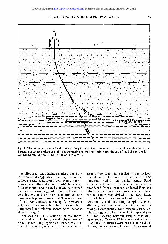
Fig. 5. Diagram of a horizontal well showing the pilot hole, build-section and horizontal or drainhole section. Structure of target horizon is as the Tor Formation on the Dan Field where the end of the build-section is stratigraphically the oldest part of the horizontal well.
A pilot study may include analyses for both micropalaeontology (foraminifera, ostracods, radiolaria and macrofossil debris) and nanno- fossils (coccoliths and nannoconids). In general, Maastr icht ian targets can be adequately zoned by micropalaeontology while in the Danian a combinat ion of both micropalaeontology and nannofossils proves most useful. This is also true of the Lower Cretaceous. A simplified version of a typical biostratigraphic chart showing both nannofossil and micropalaeontological zones is shown in Fig. 7.
Analyses are usually carried out in the labora- tory, and a prel iminary zonal scheme erected before undertaking any work at the well site. It is possible, however, to erect a zonal scheme on
samples from a pilot hole drilled prior to the hor- izontal well. This was the case on the first horizontal well on the Danian Kraka Field where a prel iminary zonal scheme was initially established from core pieces collected from the pilot hole and immediately used when the hori- zontal section was drilled a few days later. It should be noted that microfossil recovery from horizontal well ditch cuttings samples is gener- ally very good with little contaminat ion by cavings. Consequently, zonal schemes can be sig- nificantly improved at the well site especially as a 30-foot spacing between samples may only represent a difference of 1 foot in a vertical sense.
As a result of further work on the Dan Field, in- cluding the monitoring of close to 50 horizontal
at Simon Fraser University on April 20, 2012http://sp.lyellcollection.org/Downloaded from

STA
ND
AR
D
UP
PE
R
CR
ETA
CE
OU
S
ZON
E
MK
1
TEN
TATI
VE
ZO
NE
S
DA
N F
IELD
MK
IA
MK
IB
PO
TEN
TIA
L C
OR
RE
LATI
VE
E
VE
NTS
"~"1
P
seud
otex
tufa
ria
spp.
•
~---
-q
Cal
care
ous
bent
honi
c fo
ram
s.
Cal
care
ous
bent
honi
c fo
ram
s. O
?1
Ru~
locJ
Iobi
[lerin
a sp
p.O
OR
IGIN
AL
DA
N Z
ON
AT
ION
BA
SE
D O
N M
FA
-13
(UP
PE
R P
AR
T)
ii I
/ /
/
ZON
ES
DM
1
C.5
0'
kk
I D
M2C
DM
3
\ \ \
\ D
M4
PRIN
CIP
AL E
VE
NTS
LE
GEN
D I
Com
mon
Si
ngle
eve
nt
~ "lo
p O
Rar
e •
Abun
dant
To
tal r
ange
~
Base
•
Occ
asio
nal
••
Supe
rabu
ndan
t ...
..
" "~
-'q
P.
bra
zoen
sis/
acer
vulin
oide
sOfl
> P.
e/e
gans
•t~
, R
. fru
ctic
osa
G. c
lem
entia
na s
ubsp
. (?
loca
l)
~_
~
Pla
nogl
obul
ina
spp.
II,
P. el
egan
s> P
. bra
zoen
sis/
acer
vulin
oide
s R
. con
tusa
O,
P. la
evis
O,
B. d
raco
dra
co,
Pra
ebul
irni
na l
aevi
s H
. glo
bulo
sa O
, G. a
sper
0,
S. b
ecca
riifo
rmis
D
M2A
,~
--J
G. c
lem
entia
na s
ubsp
. (?
loca
l)
Pla
nogl
obul
ina
spp.
e/!
Cal
cisp
here
s I,
__
~j
P.e
lega
ns e
lega
ns I
/m,
R,
fruc
ticos
a "~
--
G, v
oltz
iana
(Ioc
al)
I R
.con
tusa
I,
S.p
omm
eran
a: G
lobo
trun
cana
arc
a ~ )
/0,
~-
C.
vela
scoe
nsis
•,
R. r
ugos
a ~:
)/0, O
. vat
iabi
lis,
)/0,
D
M2B
I
G. b
embi
x, I
noce
ram
us
(loca
l) ~-
?~F
~---
q C
alci
sphe
res
(loca
l) rn
crea
se H
. gl
obul
osa,
G. a
sper
, B.
mul
tispi
na,
Pith
onel
la s
p.,
S. p
omm
eran
a 0,
B.
drac
o cl
raco
•
~R
In
flux
radi
olar
ia (
Cen
osph
aera
spp
./C
enod
/scu
s sp
p., g
lass
y),
loca
l • r
ugos
a O
/Q,
Pith
onel
la 0
, Sp
icul
e X
~-_-
--I
R. c
ontu
sa B
, P.
e/e
gans
O,
S. p
omm
eran
a O
, P.
laev
is •
I G
. arc
a {-
.)/•,
R.c
ontu
sa,
Cen
osph
aera
spp
. (ch
alky
, loc
al)
Bryo
zoa,
Ino
cera
mus
(lo
cal)
R. r
ugos
a II,
incr
ease
agg
lutin
ated
for
amin
ifera
PR
ES
EN
T D
AN
ZO
NA
TIO
N
(UPP
ER
PA
RT
)
Fig.
6.
Dan
Fie
ld m
icro
pala
eont
olog
ical
zon
al s
chem
es s
hovi
ng (
left
) th
e ea
rly
sche
me
base
d on
MF
A-1
3 to
geth
er w
ith
stan
dard
Upp
er C
reta
ceou
s zo
ne a
t th
at t
ime
and
(rig
ht)
the
pres
ent-
day
sche
me
for
the
equi
vale
nt s
ecti
on (
repr
oduc
ed w
ith
perm
issi
on f
rom
Mae
rsk
Oli
e og
Gas
AS)
.
at S
imon
Fra
ser
Uni
vers
ity o
n A
pril
20, 2
012
http
://sp
.lyel
lcol
lect
ion.
org/
Dow
nloa
ded
from

BIOSTEERING DANISH HORIZONTAL WELLS 81
I-!.l M5B I M5A I N3A
M2 I M1 N2-N1 I
I i i ] \ - 4 ' ' '
/
v
I
MICRO-FOSSIL NANNO-FOSSIL Depth Scale 1 : 500 (feet)
Abundance Scale l cm = 2 5 %
Anornalinoides velascoensis Anomalinoides hyphalus Anomalinoides/Gavelinella spp. Cibicides/Heterolepa spp.
Gavelinella beccariiformis
Gyroidinoides subangulata Lenticulina spp.
Nodosariidae Osangularia lens Polymorphindae Quadrimorphina halli Cibicides succedens Pullenia amercana
Dentalina/Nodosaria spp.
Gavelinella bembix
Gyroidinoides nitida
Gyroidinoides quadrata
Lagena spp.
Osangularia cordierana
Pleurostomella spp.
Praebulimina laevis. Gavelinella cornplanata
Anomalinoides spp.
Anomalinoides welleri
Ramulina spp.
Fig. 7. Simplified biostratigraphic chart from the upper part of the Maastrichtian of Gorm Field. Micropalaeontological and nannofossils zones are shown on the left of the chart, while occurrences and abundances of foraminifera are shown to the right. A similar chart would also be produced for the nannofossils (after Shipp & Marshall 1994).
wells, the present-day Dan zonation (as shown in Fig. 6) with a significantly increased number of micropalaeontological data points has been developed. Individual zones are approximately 10 feet thick and can often be subdivided. Approximately 20 data points are now recog- nized in place of the four used on MFA-13 and the original single uppermost Maastrichtian zone of the traditional zonal scheme (Fig. 6). As a result of such developments it soon proved possible to monitor wells through the Maas- trichtian target zone over a distance of some
6000 feet (Fig. 8). The more recent MFB-2E well, drilled in 1996, was monitored over a horizontal distance of 11 420 feet, at the time a North Sea record.
Even greater refinement has been achieved over part of the Valdemar section, as shown in Fig. 9 which represents part of the zonation covering a 50-foot vertical section. A pilot study to establish the zonation was originally carried out on samples at 5-foot spacings through a core from a nearby well. This resulted in the micro- palaeontology and nannofossil zones shown as
at Simon Fraser University on April 20, 2012http://sp.lyellcollection.org/Downloaded from

82 D . J . SHIPP
rrl
-r
Z
rm
m
+ooI
I000 l
J !i!i!!:
1500 i
l i e •
2000 : i J i
0 500 1000 1500 2000 2500 3000 3500 4000m
VERTICAL SECTION
Fig. 8. Dan MFA-I 8 well showing the trajectory of a horizontal section maintained within the target zone (after Shipp & Marshall 1994).
M zones and N zones. During the drilling of the Valdemar-2 horizontal well, additional events were identified over this part of the section. As a result additional analyses were carried out at 1-foot spacings with the improvement in the zonation indicated by the MV zones and NV zones, where 16 micropalaeontological zones or subzones and 14 nannofossil zones and subzones are recognized over the 50-foot section studied. Some of these zones are only 1 foot in thickness.
A t the w e l l s i te
Mobilization for a well-site assignment can be very rapid as all the equipment required by the micropalaeontologist or nannofossil worker can be hand-carried to the rig.
Foraminiferal microscope work is usually carried out in the logging unit where facilities for washing and drying samples are readily avail- able. Nannofossil work is also ideally under- taken in the logging unit, although occasionally, because of the higher magnification used, excess vibration from the drill floor and shakers may necessitate setting up the microscope elsewhere.
The lag time from the cutting of a sample to its arrival at the shakers can be 1 h or more, and this reinforces the need for a rapid response to any changes. Preparation time takes approxi- mately 5rain with a further 5-10min required
for analysis in the case of both nannofossils and micropalaeontology. The lag time from the cutting of the sample to completion of analysis can therefore be upwards of 1 h, and results are often 100 feet behind the bit depth. However, this is generally within acceptable working, limits, bearing in mind that it is possible to slow down the rate of penetration or to circulate bottom-up samples when necessary.
The biostratigrapher usually tries to analyse every sample collected on the build-section, which can be as close as every 10 feet, to re- affirm the zonal scheme and to identify the correct zonal position at the start of the hori- zontal section. Once the trajectory is horizontal the sample spacing is usually opened out to 20, 40 or 60 feet depending on the rate of penetration.
It is important for the biostratigrapher to be aware of the angle at which the well is being drilled, and to establish the relationship to the dip of the beds as this can affect the number of fossils recovered. In Fig. 10 a thin bed contain- ing large numbers of a planktonic marker is illustrated. If the well is being drilled along this bed then the marker fossil will appear in abun- dant numbers as in the first case (A). If the well path cuts the bed at an angle then fewer specimens of the marker will appear in the sample (B), and if it cuts the bed at right angles only rare specimens will be recovered (C). It is also important to be aware whether a zone
at Simon Fraser University on April 20, 2012http://sp.lyellcollection.org/Downloaded from

BIOSTEERING DANISH HORIZONTAL WELLS 83
MV ZONE M ZONE NV ZONE N ZONE
MV11
Ml l NV 20a
N20
z (=3
I.-- c.~ LJ,.J
C./b
(:3 CD I_I_
O L..¢')
MV12a NV 20b
NV 21a MV12b
M12 NV 21b MV12c
MVl2d
MV13a
MV13b
MV14
MV15a
MV15b
MV16
MV17a
MV17b
MV17c
MVlTd
MV18
M13
NV 22a
NV 22b
NV 23a
N21
N22
M14 N23
NV23b
NV 24a M15 N24
M16
NV 24b
NV 25a
NV 25b
NV 26a
NV 26b
M17
M18
N25
N26
Fig. 9. Part of the Valdemar Field zonation over 50 feet of section showing an increased refinement from M (micropalaeontological) and N (nannofossil) zones, where core samples had been analysed at 5-foot spacings, to MV and NV zones, where core samples were subsequently analysed at 1-foot spacings (after Shipp & Marshall 1994).
is being entered from above or below, as the criteria for identifying the zone are likely to be different in each case. For such reasons experi- ence is vital for the successful interpretation of the zonal schemes.
It must be stressed that high-resolution bio- stratigraphy is only one of several tools available that together make it possible to geosteer a horizontal well. These other tools include 'log- ging while drilling' (LWD) or 'measurement while drilling' (MWD), hydrocarbon show eva- luation and three-dimensional (3D) seismic (Jeppesen 1994). The well-site geologist, biostra- tigrapher, MWD or LWD operator, directional driller and company man all form essential ele- ments of the well-site team, which is necessary for the success of any well.
On earlier horizontal wells in the Danish sector a single biostratigrapher carried out the work, but as knowledge of the fields improved so the degree of accuracy required increased. On the Dan Field, for example, the original requirement to stay within the Maastrichtian has changed to more specific requirements such as to follow a particular subzone that correlates to the best reservoir characteristics. In addi- tion, improvements in bit performance has meant that bit trips, which give the palaeontol- ogist an opportunity to rest, are not required so often. Consequently, it was recognized that two biostratigraphers, working 12-h shifts, were required for full 24-h monitoring. Water- injection wells drilled deeper in the reservoir may still only have one biostratigrapher on board, however, as continuous monitoring is less vital.
Case histories
Examples illustrating the contribution made by wellsite biostratigraphy to the drilling of hor- izontal wells in the Danish sector can be found in the following publications: Anderson et al. (1990), Kruse (1991), Fine et al. (1992), Jeppesen (1994) and Shipp & Marshall (1994).
The authors wish to thank the management of Robertson Research International Limited, the com- panies in the Dansk Undergrounds Consortium (Shell Olie og Gasudvinding Danmark BV, Texaco Denmark Inc. and A. P. Moller) and operator Maersk Olie og Gas AS for their consent to publish this paper and for permission to include some of their data and figures. Some parts of this paper were initially presented at GEO '94 and appeared in Selected Middle East Papers from GEO '94 and we are grateful to the organizers of that conference for permission to include such details in the present updated paper.
at Simon Fraser University on April 20, 2012http://sp.lyellcollection.org/Downloaded from

84 D . J . SHIPP
Fig. 10. Diagram to illustrate the different number of microfossils, such as planktonic foraminifera, recovered from a thin bed depending on the angular relationship of the bed to the well path. (A) When the well path parallels the bed microfossils are common. (B) When the well path cuts the beds at 45 ° microfossils are occasional. (C) When the well path cuts the beds at a right angle microfossils are rare.
References
ANDERSON, C. & DOYLE, C. 1990. Review of hydro- carbon exploration and production in Denmark. First Break, 8(5), 15 165.
ANDERSON, S. A., CONLIN, J. M., FJELDGAARD, K. & HANSEN, S. A. 1990. Exploiting reservoirs and horizontal wells: the Maersk experience. Schlum- berger Oilfield Review, 2(3), 11-21.
FINE, S., YUSAS, M. R. & JORGENSEN, L. N. 1992. Geological aspects of horizontal drilling in chalks from the Danish Sector of the North Sea. In: PARKER, J. (ed.) Petroleum Geology of North West Europe: Proceedings of the 4th Conference. Geo- logical Society, London, 1483-1490.
INESON, J. R. 1993. The Lower Cretaceous Chalk Play in the Danish Central Trough. In: PARKER, J. (ed.)
Petroleum Geology of North West Europe: Pro- ceedings of the 4th Conference. Geological Society, London, 175-183.
JEPPESEN, M. W. 1994. Geological steering of horizon- tal wells in chalk reservoirs: examples from the Danish North Sea. Bulletin of the Geological SocieO, of Denmark, 41, 138-144.
KRUSE, I. 1991. Petroleum geoscience - Danish view. First Break, 9(3), 95 106.
SHIPP, D. J. & MARSHALL, P. R. 1994. Biostratigraphic steering of horizontal wells. In: HUSSEINI, M. I. (ed.) The Middle East Petroleum Geosciences. Selected Middle East Papers from the Middle East Geoscience Conference, Bahrain, Volume 2, 849-860.
at Simon Fraser University on April 20, 2012http://sp.lyellcollection.org/Downloaded from