welcome to the world of barbeques galore outdoor …
TRANSCRIPT

Page 1
WELCOME TO THE WORLD OF BARBEQUES GALORE OUTDOOR COOKING
INSTRUCTIONS FOR ASSEMBLY AND USE OF BEEFMASTER V-SERIES BARBEQUES
For the safe use and enjoyment of your new barbeque
These instructions contain important information that needs to be followed for the safe assembly and use of your new barbeque. Please read through carefully and completely prior to assembly. Take care to remove all packaging materials & protective coatings from the bbq before first use. When unpacking the barbeque, keep it resting on its polystyrene foam base until ready to install onto the cart or build-in or island. This will avoid any damage to parts while the unit is not fixed into place. For Barbeque Head Models: G2BV, G2PBV, G2PDXB, G4BV, G4PBV, G4DXBV, G6BV, G6PBV, G6DXBV Tools required:Two adjustable spanners; One Phillips head screwdriver; One Regular screwdriver. Special tools required as well for NG conversion. See inside for details. See also instruction manuals provided separately with associated carts, side shelves, side burners and build-in kits.

Page 2
Australia has an excellent safety record when it comes to gas appliances. This reflects both the high quality of appliances sold, as well as growing consumer awareness about safety. We urge you to follow the guidelines below together with these instructions for safe use, to prevent overheating and to produce great cooking results. • This barbeque is an outdoor appliance only. Under no circumstances should it be
used indoors. This barbeque has not been approved for marine or caravan use.
• DO NOT perform any servicing on the barbeque yourself. This includes internal adjustment of the regulator and gas valves. Servicing can only be carried out by authorised technicians. DO NOT modify this appliance.
• It is important that you install your barbeque exactly as described in these instructions. In particular you should keep the barbeque clear of combustible material, and you should check for leaks whenever a new connection is made.
• DO NOT store chemicals or flammable materials near this appliance.
• DO NOT place articles on or against, or enclose this appliance.
• DO NOT spray aerosols in the vicinity of this appliance while it is in operation.
• The barbeque gets extremely hot while in use. Keep pets, children and the infirm away from the appliance until it has cooled to normal temperatures.
• It is a good idea to tie back long hair and loose clothing while cooking in case of unexpected flare ups.
• Fat fires are the most common cause of problems in barbeques. They are caused by a build-up of grease in the grease channeling tray and / or the inside of the barbeque firebox. A fat fire can be difficult to put out, and will be very dangerous if it spreads to the gas hose. You should keep your barbeque clean to avoid this occurrence. Fat fires will void the warranty. If a fat fire occurs, DO NOT try and extinguish with water, shut down the gas supply if safe to do so, close the hood if safe to do so, call the Fire Brigade on 000 if necessary.
• DO NOT transport or move the barbeque whilst it is in use or still hot because there is a risk that the contents of the grease cup will fall out.
• NEVER leave a barbeque unattended with any burners switched on. Always switch off all burners and gas supply when the barbeque is not in use.

Page 3
• USE CAUTION when touching a hot barbeque, especially on surfaces close to the
firebox or roasting hood.
• It is fine to pre-heat with all burners on HI and the hood closed, but NEVER let the temperature on the hood thermometer exceed 250°C on the hood thermometer.
• When cooking with the hood closed, turn one or more burners to LO or OFF as required to keep the barbeque from getting too hot. NEVER let the temperature on the hood thermometer exceed 250°C on the hood thermometer.
• The hood and side burner lid where used must be in the OPEN position before lighting.
• For 2 burner barbeques, when cooking with the hood closed for more than 20 minutes: NEVER exceed maximum temperature of 250°C and use the main burners on LO only.
• For 4 burner barbeques, when cooking with the hood closed for more than 20 minutes: NEVER exceed maximum temperature of 250°C and use no more than 3 main burners on LO only.
• For 6 burner barbeques, when cooking with the hood closed for more than 20 minutes: NEVER exceed maximum temperature of 250°C and use no more than 4 main burners on LO only.
• NEVER leave all burners on HI for more than 10 minutes, always stay in control by
adjusting burners to LO and OFF as required to maintain suitable cooking temperatures.
• Periodically check for gas leaks. Check for gas leaks whenever a new gas connection is made. See “Safety Leak Testing” section.

Page 4
This appliance must only be used in an above ground, open air situation with natural ventilation, without stagnant areas, where gas leakage and products of combustion are rapidly dispersed by wind and natural convection. Any enclosure in which the appliance is used must comply with one of the following:
(1) Any enclosure with walls on all sides, but at least one permanent opening at ground level, and no overhead cover. See Figure 1.
(2) Within a partial enclosure that includes an overhead cover and no more than two walls. See Figure 2 and Figure 3.
(3) Within a partial enclosure that includes an overhead cover and more than two walls (see Figure 4 and Figure 5), the following shall apply:
(i) At least 25% of the total wall area is completely open; and
(ii) At least 30% of the remaining wall area is open and unrestricted.
(iii) In the case of balconies, at least 20% of the total of the side, back and front wall areas shall be and remain open and unrestricted.
FIGURE F1—OUTDOOR AREA–EXAMPLE 1
FIGURE F2—OUTDOOR AREA–EXAMPLE 2
FIGURE F3—OUTDOOR AREA–EXAMPLE 3
Both ends open
FIGURE F4—OUTDOOR AREA–EXAMPLE 4
Open side at least 25% of total wall
30 percent or more in total of the remaining wall area is open and unrestricted
FIGURE F5—OUTDOOR AREA–EXAMPLE 5
Open side at least 25% of total wall
30 percent or more in total of the remaining wall area is open and unrestricted

Page 5
• The support structure must be only non-combustible material. Clearances of the barbeque from
combustible materials (e.g. wooden fences and gyprock walls and painted surfaces): 300mm from sides and rear; 1000mm vertically above; 10mm below. If part of the structure is composed of combustible materials, ensure that the combustible material is separated from the sides and rear of the barbeque by at least 300 mm.
• Adequate clearance around the barbeque must be provided for safe and efficient operation. The
clearances shown in the diagram below ensure that the burners have a supply of fresh air to operate correctly. Failure to provide enough fresh air to the burners can cause the production of potentially deadly noxious gases
• At least 72mm clearance is required from the rear of the build-in barbeque support bracket
body to allow the roasting hood to open freely. Refer to the diagram below for details. • Structure and installation must comply with AS/NZS 5601 including:
(1) Cylinder compartments must have permanent openings ventilating directly to the outside of the appliance consisting of either:
(a) Perforations uniformly distributed over the height of the enclosure and with a total free area of not less than 25% of the wall area; or
(b) Separate openings at high and low level such that (i) The total free area at the high level is not less than 20,000 square mm and is all within
125 mm of the top of the cylinder compartment; and (ii) The total free area at the low level is not less than 20,000 square mm and
(A) At least 25% of the required total area is within 15mm of the base of the cylinder compartment; and
(B) The total required area is within 125 mm of the base of the cylinder compartment; and (C) The openings cannot be obstructed by the gas cylinder.
Note that if a range hood is installed, it must be a minimum of 1200mm above the primary cooking surface.
(2) Where the cylinder is kept in an enclosed space underneath or near the build-in barbeque,
the following must be observed: (a) The cylinder must rest on a firm base to ensure that water will not accumulate, and that the
cylinder is clear of the surrounding soil. (b) There must be a separation panel between the gas cylinder and the barbeque so that if a
high pressure gas leak occurs, there is no direct path between the cylinder compartment and the bbq firebox.

Page 6
BBQ DIMENSIONS AND REQUIRED HEIGHT
≥345
mm
≥520
mm
≥920
mm
(fo
r P
ropa
ne o
nly)
620.3mm
WALL
9kgcylinder
Cylinder compartment ventilation
587m
m
≥ 72mm (for hood to open)
192.
5mm
177.
9mm
177.
9mm
620.
3mm
72m
m54
8.3m
m
548.3mm
Min 895 mm, Max 900 mm (4B)
Min 1215 mm, Max 1220 mm (6B)
Min 575 mm, Max 580 mm (2B)
98.8
mm
Min 50 mm gap behind the bbq for ventilation!
2B 558 mm
4B 878 mm
6B 1198 mm
CAVITY REQUIRED WIDTH AND DEPTH
100mm2-100mm
Min 50mm gap behind the bbq for ventilation!
284
mm

Page 7
Before assembling your barbeque, you must ensure your barbeque is correctly suited to the type of gas which you are going to use: LPG (Liquefied Petroleum Gas), also known as Propane or Universal LPG: Beefmaster V-Series barbeques are configured when manufactured for LPG and should have a red printed sticker near the data plate stating “UNIVERSAL LPG”. This is most commonly supplied as a portable 4 kg or 9 kg gas cylinder, which can be refilled or swapped at petrol stations or your place of purchase when empty. Follow the assembly instruction steps for how to fit and connect your portable cylinder. Some homes have twin 45 kg LPG cylinders permanently installed near an outside wall. These cylinders supply LPG gas to multiple appliances in the home via copper pipes (reticulated), and are filled as required by the gas supply company. Barbeques which are connected to twin 45 kg LPG cylinders must be installed by a licensed gasfitter, in accordance with the requirement of AS/NZS 5601,and local gas authority requirements. To change the gas type of your barbeque: Your Beefmaster barbeque was manufactured to use LPG. It can be connected to LPG without any alteration. If you wish to connect your barbeque to natural gas, it will need to be converted beforehand. This must be done only by a licensed gas fitter or an authorised gas appliance technician using the correct injectors supplied with this instruction manual and following the instructions detailed later in this manual. Connection to the natural gas supply must only be done by a licensed gasfitter. The gasfitter must issue a compliance certificate including their license details and the date of installation. Keep that certificate in a safe place in case any warranty or servicing of the barbeque is required Natural Gas: Barbeques suited to natural gas should have a black printed sticker near the data plate stating “NATURAL GAS”.This is reticulated (piped) to your home in a similar fashion to water, so there are no cylinders to refill. You will need to contact your local gas company to determine if Natural Gas is available in your area. Barbeques to be connected to Natural Gas must be installed by a licensed gasfitter, in accordance with the requirement of AS/NZS 5601 and local gas authority requirements. This Beefmaster V-Series barbeque was manufactured for use with LPG so would need to be altered by an authorised person for use with Natural Gas following the conversion instructions in this manual. If connecting to a standard Natural Gas bayonet outlet, the correct hose and governor assembly must be used (code: NGCK250VJQ) available at your nearest Barbeques Galore store. If connecting direct to the Natural Gas supply, the gasfitter will need to use a Natural Gas governor (code: RCV250Q) and appropriate pipes and fittings for your particular installation. It is extremely dangerous to use the barbeque with the wrong type of gas. Fire or explosion may result. Always conduct a leak test before use. Refer details later in this manual under “Safety leak testing”.

Page 8
There are two approaches to permanent piped installations: (1) Direct Permanent Piped Connection: Your barbeque may be permanently connected to the
Natural Gas main gas lines or LPG cylinder via copper pipe. This must be done entirely by the gasfitter, in accordance with requirements of AS/NZS 5601, and local gas authority requirements. Your gasfitter will ensure that your barbeque is permanently connected to the supply via copper pipe, the gas pressure in the line is adequate for the complete system, pipe sizes are correct, all connections are secure, and that all necessary components (such as secondary regulators and manual shutoffs) are included where regulations require them. Once this is done, the barbeque cannot be moved. It is a permanent fixture of the property. Build-in barbeques most often are connected this way.
(2) Bayonet Point: Alternatively, you can have the gas fitter terminate the gas line using a
“bayonet point”. This allows you to connect and disconnect the barbeque using a special hose and bayonet termination. Such a hose is provided in the Natural Gas conversion kit NGCK250VJQ. Follow the instructions supplied with the kit to complete the connection. For LPG bayonet installations, an appropriate hose is available from most barbeque retailers.
Even if your barbeque area already has a bayonet point, you will still need to call upon a gas fitter to ensure that gas pressure is appropriate for your barbeque and associated appliances on the same supply, and to ensure your barbeque is adjusted and functions correctly before leaving. Where a gas fitter is required, the gasfitter must test the safety and operation of the appliance before leaving, including gas pressure, ignition and burner operation. The gasfitter must issue a compliance certificate for the installation showing their licence number and the date of the installation. Keep that certificate in a safe place in case any warranty or servicing of the barbeque is required. To the installer: You must instruct the consumer on safe operation, and ensure these instructions are left with the consumer before leaving the site.
Page 9
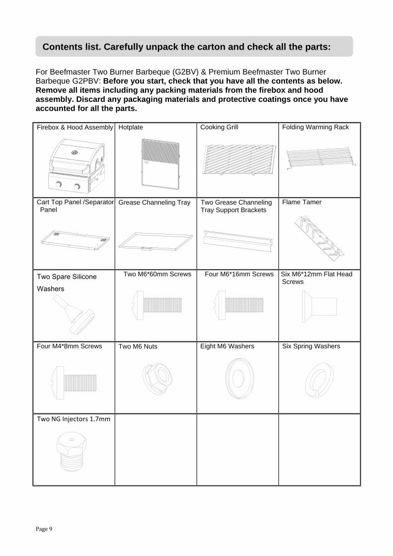
For Beefmaster Two Burner Barbeque (G2BV) & Premium Beefmaster Two Burner Barbeque G2PBV: Before you start, check that you have all the contents as below. Remove all items including any packing materials from the firebox and hood assembly. Discard any packaging materials and protective coatings once you have accounted for all the parts.
Firebox & Hood Assembly
Hotplate
Cooking Grill Folding Warming Rack
Cart Top Panel /Separator Panel
Grease Channeling Tray
Two Grease Channeling Tray Support Brackets
Flame Tamer
Two Spare Silicone Washers
Two M6*60mm Screws
Four M6*16mm Screws
Six M6*12mm Flat Head Screws
Four M4*8mm Screws
Two M6 Nuts
Eight M6 Washers
Six Spring Washers
Two NG Injectors 1.7mm
Contents list. Carefully unpack the carton and check all the parts:

Page 10
For Beefmaster Deluxe Two Burner Barbeque (G2DXBV): Before you start, check that you have all the contents as below. Remove all items including any packing materials from the firebox and hood assembly. Discard any packaging materials and protective coatings once you have accounted for all the parts.
Firebox & Hood Assembly
Hotplate
Cooking Grill
Folding Warming Rack
Cart Top Panel / Separator Panel
Two Grease Channeling Tray Support Brackets
Grease Channeling Tray
AC Transformer
Ceramic Tile Bracket
Two Ceramic Tiles
Two M6*60mm Screws
Four M6*16mm Screws
Four M4*8mm Screws
Six M6*12mm Flat Head Screws
Eight M6 Washers
Six Spring Washers
Two M6 Nuts
Two Spare Silicone Washers
Two NG Injectors 1.7mm
Contents list. Carefully unpack the carton and check all the parts:

Page 11
For Beefmaster Four Burner Barbeque (G4BV), Premium Beefmaster Four Burner Barbeque (G4PBV) , Beefmaster Six Burner Barbeque (G6BV), & Premium Beefmaster Six Burner Barbeque (G6PBV): Before you start, check that you have all the contents as below. Remove all items including any packing materials from the firebox and hood assembly. Discard any packaging materials and protective coatings once you have accounted for all the parts. Firebox & Hood Assembly
Hotplate Two Cooking Grills
Folding Warming Rack
Cart Top Panel / Separator Panel
Two Grease Channeling Tray Support Brackets
Two x Flame Tamer (4B)Four x Flame Tamer (6B)
Grease Channeling Tray
Grease Cup
Foil Dish
Two M6*60mm Screws
Four M6*16mm Screw
Seven M6*12mm Flat Head Screws
Four M4*8mm Screws
Two M6 Nuts
Eight M6 Washers
Six Spring Washers
Two Spare Silicone Washers
NG Injectors 1.7mm Four for 4B; Six for 6B
Contents list. Carefully unpack the carton and check all the parts:

Page 12
For Beefmaster Deluxe Four Burner Barbeque (G4DXBV) & Beefmaster Deluxe Six Burner Barbeque (G6DXBV): Before you start, check that you have all the contents as below. Remove all items including any packing materials from the firebox and hood assembly. Discard any packaging materials and protective coatings once you have accounted for all the parts. Firebox & Hood Assembly
Rotisserie Set Motor Bracket
Hotplate
Two Cooking Grills
Folding Warming Rack DC Motor
AAA 1.5V Battery
AC Transformer
Ignition Module
Motor 240V Adaptor
Cart Top Panel / Separator Panel
Two Grease Channeling Tray Support Brackets
Grease Channeling Tray
Grease Cup
Foil Dish
Four x Ceramic Tiles (4B) Eight x Ceramic Tiles (6B)
One Ceramic Tile Rack (4B) Two Ceramic Tile Racks (6B)
Two M6*60mm Screws
Four M6*16mm Screws
Seven M6*12mm Flat Head Screws
Eight M4*8mm Screws
Two M6 Nuts
Eight M6 Washers
Six Spring Washers
Two Spare Silicone Washers
NG Injectors 1.7mm Four for 4B; Six for 6B
NG Injector Cap 1.54mm
Contents list. Carefully unpack the carton and check all the parts:

Page 13
If you are assembling a cart model or steel island, make sure you have the separately supplied steel cart (code MC2BV or MC2DXB for 2 burner, code MC4BV or MC4DXB for 4 burner, code MC6BV or MC6DXB for 6 burner). Assemble the cart(s) before you start on the barbeque head assembly using the instruction manual supplied separately with the cart. If you are assembling multiple units together (e.g. 2 burner and a 4 burner and a Range unit to make one bbq island), assemble each of the bbqs / heads to their respective carts before joining the carts. If you are fitting side shelves and / or side burners, make sure you have the separately supplied pack of two folding shelves (code MCBFOLDV) or pack of one Premium shelf + one stainless steel side burner (code MCBSBSHELFV) or pack of one Deluxe shelf + one cast iron side burner (code MCDXBSBSHELFV). If you are assembling a build-in or an island, make sure you have the separately supplied build-in kit (code BRBIKV). Double check all dimensions and clearances before committing to any design or construction expense. If you purchased a pre-fabricated island, verify that you have matching size island and barbeque head, and assemble the island before you start on the barbeque head assembly. If you want to run up to two adjacent gas modules (e.g. 2 burner and 4 burner) from a single gas supply, you will need separately supplied corrugated gas extension pipe (code: CBGASEXT). Check with a gasfitter before connecting multiple items from the one gas supply to ensure it can be done safely.
Assembly instructions

Page 14
STEP 1 (ALL MODELS): Position the Grease Channeling Tray Support Brackets. WHAT YOU NEED
Two Grease Channeling Tray Support Brackets Four M4*8mm Screws Screw the left and rights Grease Channeling Tray Support Brackets to the Separator Panel. Make sure the pre-fitted stopper nuts are at the top back inner positions as shown below. Tighten the screws firmly.
STEP 2 (DELUXE MODELS ONLY): Fit the transformer WHAT YOU NEED One Transformer with Integral Bracket. Four M4*8mm Screws
Locate the Transformer into place on the underside of the top panel as shown below and lock into place with four M4*8mm screws.
Note the stopper nuts inwards upper positions
Grease Channeling Tray Bracket Four M4*8mm Screws
Back
Front
Assembly instructions (continued)

Page 15
STEP 3 (FOR DELUXE MODELS 4B AND 6B ONLY): Attach the rear burner ignitor
WHAT YOU NEED One ignition module and cover box One AAA 1.5V battery
(a) Open the cap of the Ignition Module and insert the Battery with the positive terminal
outwards as shown.
(b) The Cover Box has two flat tabs. Slide the tab into the flat bracket on the underside of the separator panel until the cover box is firmly in place.
These next two steps assume that you have already assembled the cart using the instructions included separately with the cart. (For build-in or island models, skip now to STEP 7.) STEP 4 (CART MODELS ONLY): Fix the cart/ cabinet separator panel into place. WHAT YOU NEED Six M6*12mm Flat Head Screws (2B) Seven M6*12mm Flat Head Screws (4B,6B)
Assembly instructions (continued)

Page 16
(a) If the cart Door Beam is already attached, detach it by removing the four screws as shown.
门横梁
(b) Locate the Cart Top Panel in place and fix it to the cart, using two M6*12mm
screws each side and three screws at the back as shown. (Note that 2B has only two screws at the back). Don’t fully tighten the screws yet.
(c) Refit the Door Beam into place using the four screws aside from part (a). Once the
Door Beam is in place, fully tighten all the screws holding the cart Top Panel and the Door Beam.
门横梁
Door Beam
Door Beam
Assembly instructions (continued)

Page 17
STEP 5 (CART MODELS ONLY): Fix the firebox and hood assembly onto the cart.
WHAT YOU NEED Four M6*16mm Screws Four Spring Washers Four M6 Washers
(a) With help, carefully position the firebox and hood assembly onto the cart. As it is
lowered into place, the gas hose and regulator (and the electrical leads for deluxe models) will need to be carefully threaded through the rubber grommet access hole in the cart top panel.
(b) Remove the firebox side panels as shown, and keep aside the twelve removed screws and the side panels for use in part (d).
(c) Fit and firmly tighten the four M6*16mm Screws, Spring Washers and Washers as shown below, so that the head is fixed to the cart. The spring washer fits against the screw head. The M6 washer fits against the firebox.
(d) Replace the firebox side panels, fit and firmly tighten the twelve screws from part (a).
STEP 3a STEP 3b
STEP 3c STEP 3d
Four M6*16mm Screws Four M6 Washers Four Spring Washers
Assembly instructions (continued)

Page 18
STEP 6 (ONLY IF JOINING ADJACENT BARBEQUES): Join the carts and fireboxes.
If you are joining two carts and barbeques together, e.g. a 2B and 4B to make a 6B, then first assemble each head onto its respective cart as above. Adjust the cart heights to match each other as outlined in the cart assembly manual, and then join the adjacent carts and fireboxes as detailed below.
(a) Bolt the adjacent carts together
WHAT YOU NEED Four M6*16mm Screws Four M6 Nuts Join the two carts using Four M6*16mm Screws, and Four M6 Nuts as shown below:
Follow the instructions that came with the cart to properly level the carts and if necessary, adjust the castors, so that all castors are simultaneously in contact with the ground once the carts are level. Note that unless the ground is perfectly level, the castor heights may need adjustment each time the cart is moved to a different position in order to level the doors.
Note that doors, cart top panels and barbeque heads are not shown here for clarity, but should already be in place.
Assembly instructions (continued)
Note that doors, cart top panels and barbeque heads are not shown here for clarity, but should already be in place.
Page 19
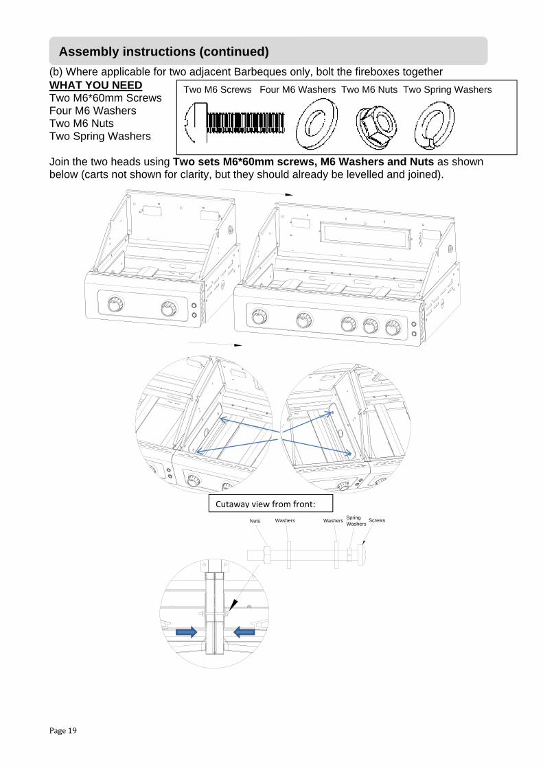
(b) Where applicable for two adjacent Barbeques only, bolt the fireboxes together WHAT YOU NEED Two M6*60mm Screws Four M6 Washers Two M6 Nuts Two Spring Washers Join the two heads using Two sets M6*60mm screws, M6 Washers and Nuts as shown below (carts not shown for clarity, but they should already be levelled and joined).
Washers ScrewsSpringWashers
WashersNuts
Two M6 Screws Four M6 Washers Two M6 Nuts Two Spring Washers
Cutaway view from front:
Assembly instructions (continued)

Page 20
STEP 7 (ONLY IF ATTACHING SIDE SHELVES, SIDE BURNER or BUILD-IN BRACKET): Refer now to the instructions separately supplied with the Side Shelves, Side Burner and Build-in Brackets. Follow those instructions to fit the side shelves and side burner or build-in brackets.
Assembly instructions (continued)

Page 21
STEP 8 (FOR 4B and 6B BARBEQUES ONLY): Fit the Grease Cup and Foil Dish. Grease Cup Foil Dish Put the Foil Dish into the Grease Cup, then fit the Grease Cup into the Cart Top Panel as shown.
STEP 9 (FOR ALL MODELS): Locate the grease channeling tray into position. Slide the Grease Channeling Tray into the support brackets on the separator panel, so that it is under the bbq, all the way back to the stoppers. If you have a cart, you need to open the doors to access the grease channeling tray. Only remove the Grease Channeling Tray and/or the Grease Cup for cleaning when the bbq is OFF and has cooled down.
Assembly instructions (continued)

Page 22
STEP 10 (FOR STANDARD AND PREMIUM ONLY): Fit the flame tamer(s) 2B One Flame Tamer 4B Two Flame Tamers 6B Four Flame Tamers The Flame Tamers fit above each burner in the cooking grill portion of the barbeque only. Flame tamers are not required underneath the hotplate. The correct position for each flame tamer is on the lower support shoulder in the firebox held in place by the locating dimples on the support shoulder. The cooking grill and hotplate positions can be switched in your barbeque, make sure the flame tamers are always positioned under the cooking grill. If you purchase optional extra grills, you will also need extra flame tamer(s) so that each burner under the grill section is covered by a flame tamer.
STEP 11 (FOR DELUXE MODELS ONLY): Position the Ceramic Tiles and Bracket 2B Two Ceramic Tiles & One Ceramic Tile Bracket 4B Four Ceramic Tiles & One Ceramic Tile Bracket 6B Eight Ceramic Tiles & Two Ceramic Tile Brackets Place the Ceramic Tiles onto the Ceramic Tile Bracket, and then fit the Bracket (with tiles) onto the lower support shoulder of the firebox. The Bracket should be positioned centrally over the burner(s) that are under the cooking grill. Each bracket should be located in place by the dimples in the support shoulder. If the hotplate and the cooking grill positions are swapped, make sure that the Ceramic Tiles / Bracket(s) are re-adjusted to be under the cooking grill. If you purchase extra cooking grill(s) for 2B / 4B to replace the hotplate, you will also need an extra set of Ceramic Tiles / Bracket to fit under the extra cooking grill. Note for 6B that maximum ceramic tiles that can fit is for 2/3 cooking grill.
Assembly instructions (continued)

Page 23
STEP 12 (FOR ALL MODELS: Position the cooking grill and hotplate WHAT YOU NEED 2B One cooking grill and one hotplate 4B Two cooking grills and one hotplate 6B Two cooking grills and one hotplate Place the Cooking Grill(s) on the upper support shoulder in the firebox as shown. Position the cooking grill(s) above the flame tamer or ceramic tiles. There is no need to place flame tamers or ceramic tiles underneath the hotplate. Position the Hotplate on the upper support shoulder in the firebox as shown Depending on the configuration you may need to align the tabs on the side of the hotplate with the gaps in the side of the cooking grills. The hotplates are deliberately designed to try and prevent using too much hotplate. Too much hotplate can overheat the bbq, and possibly dangerously damage some components. Using too much hotplate voids the barbeque warranty. NEVER use more hotplate than originally supplied with the barbeque, except for the 6B, it is OK to add one extra piece. Maximum hotplate limits: 2B: half of the primary cooking surface; 4B: half of the primary cooking surface; 6B two thirds of the primary cooking surface.
STEP 13 (FOR ALL MODELS): Position the warming rack The extendable Warming Rack hooks onto the side windshield and into the locating holes in the windshield back panel. If you have a cart, the warming rack can hook onto the back of the cart for storage when not required.
Assembly instructions (continued)

Page 24
STEP 14 (FOR DELUXE MODELS 4B AND 6B ONLY): Attach the rotisserie WHAT YOU NEED One Motor Bracket One Motor 240V Adaptor One DC Motor
(a) Fit the motor bracket Remove the two M6*15mm screws, washers and hex nuts that come pre-assembled with the motor bracket.Use them to assemble the Motor Bracket to the right wind shield by using as shown.
(b) Attach the motor
(c) The DC Motor can be powered with two D-Cell batteries (not included), otherwise,
remove the batteries and connect the Motor 240V Adaptor to the motor. Follow all safety precautions with the adaptor to keep it safe and dry and away from hot surfaces. Use only outdoor power extension cords and safe circuits.
Assembly instructions (continued)

Page 25
(d) If using the rotisserie, first remove the warming rack. For cart models, the warming rack can be stored when not in use, by attaching it to the back of the cart. For cart models, the rotisserie shaft and prongs can be stored when not in use on the back of the cart by hooking the prongs into the cart top vents. When required, assemble the Rotisserie as shown below. The handle should be removed during cooking. The support collar fits into the right windshield as shown and should be tightened to the shaft to prevent the shaft from dislodging from the motor. If the shaft has multiple sections, they should be very firmly tightened to each other using two spanners to prevent the two parts accidentally separating during use. Note that the thread may be left hand thread to minimise accidental loosening! Ensure that items on the rotisserie are properly balanced and rebalanced if necessary during cooking. An optional counterbalance is available if required. It is not recommended to exceed 4kg total load on the rotisserie shaft.
STEP 15 (FOR DELUXE MODELS ONLY): Joining the ignition and lighting connection points.
(a) Connect the rear ignition wires to the ignition module as shown. The ignition module can slide out for easier access and to change the battery.
The two rear ignition two yellow wires connection point is this side.
The rear ignition single black wire connection point is this side.
Assembly instructions (continued)

Page 26
(b) Connect the lighting cable to the transformer. Screw the dust cover in place firmly.
I/PO/
P
12
12
DO NOT CONNECT TO GAS SUPPLY YET! The rear burner ignition should make a continuous clicking noise when the rear burner control knob is pressed IN. If there is any problem, check the battery charge, check the battery orientation, check the connections, check the spark point gap, check the bulbs. The Control panel push buttons should switch the Halogen hood lights and the control panel LED lights on and off. The push buttons should be lit whenever there is power coming from the transformer. If there are any problems, check the power supply, check the connections, try the push button switches again. Troubleshooting guide at the back of this manual has details on replacing bulbs and LEDs.
Assembly instructions (continued)
Halogen Hood Light Terminals (pre –assembled)
Rear Ignition Two Yellow Wires Connection Point
Rear Ignition Single Black Wire Connection Point
Lighting Cable Connection Point
Halogen Hood Light Terminal (pre –assembled)
Control Panel Terminal (pre –assembled)
LED Control Panel Connection Point with Control Panel Switch Connection Point (pre –assembled)
Transformer

Page 27
STEP 16: SHARING GAS SUPPLY BETWEEN ADJACENT MODULES: ALL Beefmaster V-Series gas modules have independent gas supply, but it is possible if required for only these combinations of maximum two adjacent joined modules from the same gas supply: 2B and adjacent 2B can run from the same gas supply. 2B and adjacent 4B can run from the same gas supply. 2B and adjacent Range can run from the same gas supply. One side burner attached to any of these combinations is allowable. WARNING: ANY OTHER COMBINATIONS OR EXTENDED COMBINATIONS MAY NOT BE SAFE. CHECK WITH YOUR GASFITTER FOR DETAILS. ONE GAS SUPPLY, HOSE AND REGULATOR ASSEMBLY MUST STILL BE USED FOR INDIVIDUAL MODULES. Adjacent (e.g. 2B + 4B) shared gas supply assembly: WHAT YOU NEED: One separately supplied corrugated gas pipe (code CBGASEXT). Take out the grease channeling trays. Using two spanners (one to hold the manifold, one to turn the cap), disconnect the gas tube cap from the left manifold side of the right side bbq. Using two spanners, (one to hold the manifold, one to turn the nut), disconnect the hose and regulator from the right manifold side of the left side bbq.
(a) Remove the grease channeling tray and use two spanners to disconnect the cap from the manifold outlet (use one spanner to hold the manifold the other to loosen the cap).
(b) Thread the corrugated gas pipe between the two bbqs as shown. Tighten the pipe connections to each barbeque using two spanners. Perform a leak test as outlined in following section under “Safety leak testing”. You will need to bend the pipe a little to help guide it into place.
Assembly instructions (continued)

Page 28
If you are using Natural Gas or connecting to a reticulated supply, refer to details at the start of this manual under “Checking the gas type and supply”. If you are using a portable LPG gas cylinder, place the filled LPG cylinder into the right side of the cabinet, so that it sits inside the round cut out in the base shelf (or if your model has a slide out cylinder drawer, sit the cylinder into the round cut out in the cylinder drawer). Take the hose that came with the barbeque, check that it has a rubber seal on the regulator end of it, and connect this end of the hose to the gas cylinder. You won't need a spanner here. Just turn the fitting in an anticlockwise direction and hand tighten as much as you can. This should seal it sufficiently. Ensure the gas cylinder is secure. Conduct a leak test as follows before use.
Connecting the gas cylinder
Page 29
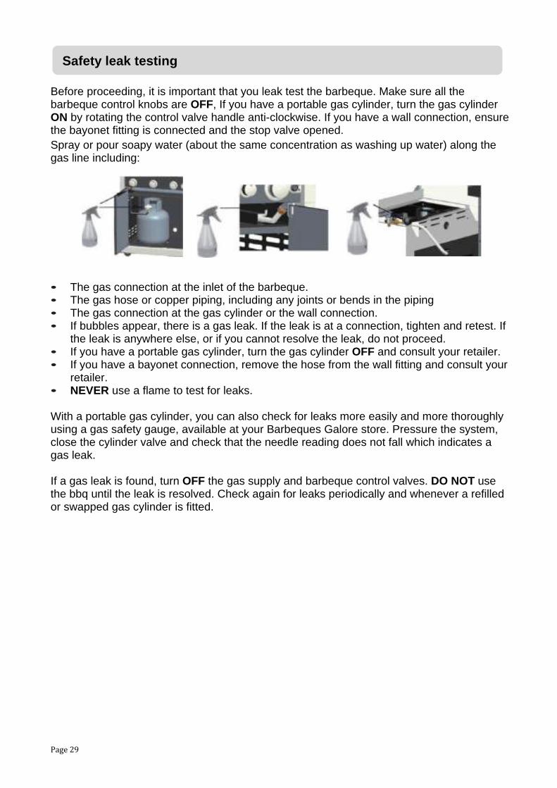
Before proceeding, it is important that you leak test the barbeque. Make sure all the barbeque control knobs are OFF, If you have a portable gas cylinder, turn the gas cylinder ON by rotating the control valve handle anti-clockwise. If you have a wall connection, ensure the bayonet fitting is connected and the stop valve opened. Spray or pour soapy water (about the same concentration as washing up water) along the gas line including: • The gas connection at the inlet of the barbeque. • The gas hose or copper piping, including any joints or bends in the piping • The gas connection at the gas cylinder or the wall connection. • If bubbles appear, there is a gas leak. If the leak is at a connection, tighten and retest. If
the leak is anywhere else, or if you cannot resolve the leak, do not proceed. • If you have a portable gas cylinder, turn the gas cylinder OFF and consult your retailer. • If you have a bayonet connection, remove the hose from the wall fitting and consult your
retailer. • NEVER use a flame to test for leaks. With a portable gas cylinder, you can also check for leaks more easily and more thoroughly using a gas safety gauge, available at your Barbeques Galore store. Pressure the system, close the cylinder valve and check that the needle reading does not fall which indicates a gas leak. If a gas leak is found, turn OFF the gas supply and barbeque control valves. DO NOT use the bbq until the leak is resolved. Check again for leaks periodically and whenever a refilled or swapped gas cylinder is fitted.
Safety leak testing

Page 30
Lighting the barbeque is easy, but must be done with due care. Ensure to start with all the control knobs in the OFF position. Make sure that the gas is turned on at the supply. Also, if your barbeque has a roasting hood or side burner, ensure that the hoods and lids are open and up. Note carefully that failure to follow the lighting procedures correctly can lead to a hazardous condition.
Main burners and optional side burners flame thrower ignition: This ignition system works by throwing a flame to the side of the burner to light it. Push the knob IN and turn it anticlockwise to the HI position. There should be a click as the ignition fires. Keep holding the knob pushed IN until the burner ignites. You may need to push IN and turn the knob anticlockwise again several times before ignition, especially after a new gas connection or if the bbq has had the gas line purged last shutdown.
Main burners and optional side burners manual ignition: You can light individual burners manually by holding a lighted match next to a burner, then pushing IN and turning that burner control knob anticlockwise to HI. You can access the main burners from underneath the barbeque or from a hole in the side of the barbeque body.
Deluxe 4B & 6B models rear burner: Light this burner in the same way as the main burners. This burner uses the electronic ignitor, so make sure the battery is in place and has charge. Once lit, the burner knob needs to be held pushed IN on HI for around 20 to 40 seconds until the rear burner glows red. If you release the knob too soon, before the burner has preheated, then the flame failure override system will shut down the rear burner.
If you have difficulty lighting:If the burner doesn’t light first go, return the knob to the OFF position, then try to light the burner a couple more times. If the burner still does not light, wait a few minutes to allow the gas to disperse before trying again. If satisfactory operation cannot be achieved, consult your retailer before proceeding.
Controlling the flames:The main burners and side burners have three basic positions: OFF, HI and LO. You can achieve any flame height between LO and HI by rotating the barbeque control knob between these positions.
Note that the rear burner where fitted, does not have a low setting, only HI and OFF.
Special note: “Blowback” is a situation where the flame burns inside the burner, towards the front. It can be recognised by a sharp roaring sound coming from the burner. It is not dangerous unless it is allowed to persist. If this occurs, simply turn the burner off, wait a few seconds, then relight.
Lighting the bbq

Page 31
Look underneath the barbeque so that you can see the flames. They should be a soft blue color with yellow tips. If the flames are too yellow, there is too much gas and not enough air. The flame will be inefficient and will give off too much smoke.
If the flame is too pale, there is too much air and not enough gas. If either of these situations occurs, then you will need to adjust the burners. Wait for the burners to cool down, and then remove them from the barbeque (details in Care & Maintenance section). You will see a screw on the right side of each burner. Screw it in to increase the yellow tipping, and screw it out to reduce the yellowness of the flame. You may need to loosen the lock nut that keeps the screw in position. Be sure to retighten the lock nut when you have finished. If you are unable to set the flame correctly, you should consult your retailer before further use.
Turning OFF When you’ve finished cooking, leave the burner controls on HI for a maximum of 5 minutes to burn off excess grease from the burner and other surfaces. To turn the barbeque off, it is best to turn OFF the cylinder first, and allow all the gas left in the hose to burn off. This will only take a few seconds. Then go back and turn OFF all burner controls. It is okay to leave the cylinder connected to your barbeque while it’s not in use, but it is much safer to turn the gas cylinder OFF when it is not in use. If your barbeque is connected to Natural Gas or piped LPG, you can simply turn the burner controls OFF. If you have a hose connection with a shut off valve, it is much safer to turn the gas supply OFF when the barbeque is not in use. Note carefully: Failure to follow these shutdown procedures correctly can lead to a hazardous condition.
The primary cooking surfaces: (hotplates and grills) are cast iron with a fused on matt vitreous enamel finish. No “curing “is required, but you should give these and the warming rack a thorough wash and rinse with regular dish washing detergent and fresh water before first use. For ongoing protection of the cooking surfaces, follow the procedures in the Cleaning, Storage and Maintenance sections.
Checking and adjusting the flames (for Cast Iron main burners only):
First time use

Page 32
The 4 and 6 Burner barbeques are equipped with a two-stage grease drainage system. Food residue drops down to the grease channeling tray, then falls through the centre hole into the grease cup. It is a good idea to line the main grease channeling tray with aluminium foil to assist with cleaning. Ensure there is a hole in the foil to allow fats and oils to drip through into the grease cup below. Also, placing fat absorbent material into the grease cup will avoid splashing and overflowing when the container starts to fill. Suitable fat absorbent material is available from your Barbeques Galore store. Avoid using fat absorbent material in the 4B and 6B main grease channeling tray, keep that tray clean and clear so grease can flow to the grease cup.
The 2 Burner barbeque is equipped with a single stage grease drainage system. Food residue drops directly into the grease channeling tray. It is a good idea to line the grease channeling tray with aluminium foil to assist with cleaning. Placing fat absorbent material into the 2B grease channeling tray will assist greatly with cleaning. Suitable fat absorbent material is available from your Barbeques Galore store.
The grease channeling trays and grease cup should be emptied, cleaned and refitted regularly. It is strongly recommended to do so every use, especially if cooking very fatty or oily foods like chops and sausages. If not emptied, eventually an uncontrolled fat fire is very likely to occur. Fat fires are very dangerous and not covered under warranty. If a fat fire occurs, do not try and extinguish with water as that will usually spread and accelerate the fire and make the situation worse. If safe to do so, shut the gas supply OFF. If safe to do so, close the roasting hood. Use only dry powder fire extinguisher. If necessary call the fire brigade, In Australia, dial 000.
Preparing to cook
Once the cooking surfaces have been cleaned, rinsed and dried, lightly coat them with cooking oil. This will reduce issues with food sticking. Light the burners and leave on HI with the roasting hood closed for about 3-5 minutes to warm the barbeque up. Once the barbeque is warmed up, you should set the burners to your desired cooking temperature. You're now ready to start cooking up a feast.
Flare-ups are caused by fats, juices and oils from the food igniting in sudden burst of flame that come up over the grill. A little bit of flare up as well as the resulting smoke is a good thing. It's what gives barbequed food that unique outdoor flavour. But if it happens too often, or if the flame lasts more than a couple of seconds, your food will char, so you need to control it.
The Beefmaster is equipped with either flame tamers or ceramic tiles that minimise direct contact between the burner flames and the food. These greatly reduces flare in most circumstances, however for very high fat content foods, some further measures may be necessary:
• Trim excess fat off your meat.
Grease Management and preparing to cook
Controlling flare up

Page 33
• The burner controls may be up too high, turning them down before flare ups occur will
usually prevent it happening in the first place. Adjust the burners to lower temperatures or even turn some burners OFF and keeping the roasting hood closed will reduce flare and usually produce significantly better tasting and healthier food.
• Moving the meat away from the flare up will also reduce the problem. Note that when all burners are on, the area of grill closest to the hotplate can be the hottest part of the grill.
• Try cooking on the warming rack with the hood closed. It is further from the flames and has more even temperature levels than the hotplate. Though it cooks slower, it gives superb results with much less attention for foods that are easy to burn on the grill like sausages, vegetables and fatty chops.
• Some very fatty foods can only be cooked on the hotplate or indirectly with the hood closed (see later information on indirect cooking).
• NEVER add more hotplates to the barbeque than originally supplied (except 6B can have up to two thirds hotplate).
It’s easy to keep your food moist and succulent on a barbeque by following these guidelines: • Use tongs instead of a fork when turning meat and poultry. A fork pierces the flesh and
causes the juice to seep out. • Resist the temptation to keep turning meat over. Juices tend to rise to the top of a piece
of meat and then settle. Each time you turn the meat over, the juices are lost. It's better to quickly sear the meat on HI each side (about half a minute) then with the burner controls down near LO, leave the meat cook on one side at a time, turning once only before serving. Alternately, turning the meat almost continually is another way to retain juiciness, but it is much more work.
• If you like salt with your food, try adding it at the end instead of before or during cooking. Salt draws the natural moisture out of the food and dries it out.
• Baste food with light marinade or canola oil a couple of times while cooking, though watch out for excessive flare-up if too much oil is used.
• Using a roasting hood as outlined later in these instructions is an excellent way to preserve moisture and succulence and takes the hard work out of barbeque cooking.
• Although cooking on the hotplate looks easier, cooking on the grill gives you a more authentic barbeque flavour. Natural juices drip onto the flame tamer or ceramic tiles and then vapourise, with the vapours penetrating flavour back into the food.
• As an alternative to simply grilling, try marinating your meat, fish, poultry or vegetables first. The longer you leave the food to stand in the marinade, the more thoroughly the flavour will soak through. Several pre-made marinades are available and good recipes are easy to come by. It is best to leave food standing in the refrigerator.
• If you use a tomato or sugar-based sauce for basting, apply it in the last 5-10 minutes of cooking. Using these sauces over a longer period of time will result in over-browning.
• To prevent meat from curling, slash the remaining fat at roughly 5cm intervals, taking care not to cut into the meat.
• Avoid burning or charring food as this has been shown to be unhealthy. NEVER leave cooked food standing for too long before eating.
Controlling flare up (continued)
Cooking tips

Page 34
Cooking with the Hood Closed:
Using the roasting hood traps heat, moisture and flavour that is normally Iost on an open top barbeque. Your Beefmaster barbeque is designed with plenty of power to heat up quickly with the hood open or closed. With the hood closed and the barbeque pre-heated, it is important to then switch some burners to LO and others to OFF in order to not overheat the barbeque which could result in increased temperature hazards and burning your food. For covered cooking, there are two basic ways to cook: (A) Direct Cooking and (B) Indirect Cooking. (A) Direct Cooking Method: This is when you place food directly over the lit burners, either on the cooking grill or the hotplate. This method is great for frying, searing and grilling, especially with thinner cuts and foods that require shorter cooking time. Cooking takes less time than with the hood open, and the results are more tender and more juicy. Preheat the barbeque with all burners on HI and the hood closed for 5 minutes. lmportantly, once the barbeque is pre-heated and the hood is closed, heat is trapped around the food, so the burners will only need to be on LO and in many cases, some of the burners OFF. Heat from the lit burners will circulate all through the hood cooking quite evenly. Quite close attention needs to be paid to the food, and the burners frequently reset to LO or OFF as required to prevent overheating. Don’t be afraid to open the hood often to check progress. You are in full control of the temperature by turning burners higher, lower or OFF as required. The gas burners will respond instantly and powerfully to your control. Most importantly, use the hood thermometer as a warning guide that the barbeque is too hot. For grilling most foods, aim to keep the thermometer below 200°C to avoid burning. NEVER let the temperature exceed 250°C or the barbeque can dangerously overheat and burn your food. A separate probe thermometer is available as an accessory from all Barbeques Galore stores. This takes the guesswork out of knowing when your food is cooked.
Covered cooking

Page 35
(B) Indirect Cooking Method: This is when you place the food only above burners that are OFF. The other burners are adjusted in combinations of LO and OFF to maintain constant lower roasting temperatures.
This method is ideal for thicker cuts of meat, legs of lamb, pork, shoulders of beef, whole chickens and whole fish. Moist, hot air rises from the lit burners and circulates around the food, trapping juices and flavour. Even cakes and breads can be cooked in your barbeque this way. Cooking low and slow allows the food to cook completely through without burning on the outside, yet remaining juicy and tender on the inside. Best results are achieved by placing your roast in a rack and that rack in the drip pan. The roast is elevated to allow heat to circulate all the way around, and water, wine, juices, herbs can be added to the drip pan to help flavour the roast and make a baste or gravy. The side of the warming rack away from the flames is also great for indirect cooking. Preheat the barbeque with all burners on HI and the hood closed for 5 minutes. lmportantly, once the barbeque is pre-heated and the hood is closed, heat is trapped around the food, so normally half of the burners need to be turned OFF. The other burner(s) may need to be turned to LO. Heat from the lit burners will circulate all through the hood cooking quite evenly. On a 2 burner barbeque, the burner under the grill on LO or HI and the burner under the hotplate OFF is usually the best setting for roasting. The roast may need to have a half turn during cooking for even browning. Place the roast rack in the drip pan onto the hotplate. On a 4 burner barbeque, two burners under the grills on LO and two burners under the hotplate OFF is usually the best setting for roasting. The hotplate can be positioned left or right in the barbeque. The roast may need to have a half turn during cooking for even browning. Place the roast rack in the drip pan onto the hotplate.
Covered cooking (continued)
Page 36
On a 6 burner barbeque, three or four burners under the grills on HI and the other burners all OFF is usually the best setting for roasting. The hotplate can be positioned left or right or in the middle of the barbeque. The roast may need to have a half turn during cooking for even browning. Place the roast rack in the drip pan onto the hotplate. Contrary to some beliefs, the slower and lower (temperature) the food is cooked, the more even, tender and juicier the results will be. Importantly, use the hood thermometer as a warning guide that the barbeque is too hot.
For roasting most foods, aim to keep the thermometer around 180°C to avoid burning. Note that the temperature at the roasting rack maybe higher than the temperature measured at the hood thermometer. For short periods of browning only, or for 10 minutes to make pork crackling, aim for around 230°C. Note that the temperature at the roasting rack may be higher than the temperature measured at the hood thermometer and most foods will quickly burn at this setting. For smoking, lower temperatures and longer cooking times will result in more intense smoke flavour and more tender meats. Aim for around 125°C. Note that temperature at the roasting rack may be higher than the temperature measured at the hood thermometer. Always use a probe thermometer to ensure that the meat has cooked all the way through to the right temperature. Great chefs will tell you that most meats need to “rest” away from the heat of the barbeque before carving or serving for a several minutes to allow the moisture pushed to the surface to redistribute. If you don’t rest the meat, moisture that has pooled near the surface will run out and the rest of the roast will be quite dry. Use the few minutes while resting the meat to open the barbeque hood, turn all burners to HI for 2 or 3 minutes to burn off food residue. After 3 minutes, turn the barbeque OFF at the gas supply and then OFF at the control knobs. While the cooking surfaces are still hot, take a long-handled brush or scraper and remove remaining oil and food residue. You should use an oven mitt to avoid burns. 3 minutes now will save 30 minutes next barbeque. NEVER let the temperature exceed 250°C or the barbeque can dangerously overheat and burn your food. A separate probe thermometer is available as an accessory from all Barbeques Galore stores. This takes the guesswork out of knowing when your food is cooked. Always remember to switch the barbeque OFF once you are finished cooking.
Covered cooking (continued)

Page 37
• It is fine to pre-heat with all burners on HI and the hood closed, but NEVER let the temperature on the hood thermometer exceed 250°C on the hood thermometer.
• When cooking with the hood closed, turn one or more burners to LO or OFF as required to keep the barbeque from getting too hot. NEVER let the temperature on the hood thermometer exceed 250°C on the hood thermometer.
• The hood and side burner lid where used must be in the OPEN position before lighting.
• For 2 burner barbeques, when cooking with the hood closed for more than 20 minutes: NEVER exceed maximum temperature of 250°C and use the main burners on LO only.
• For 4 burner barbeques, when cooking with the hood closed for more than 20 minutes: NEVER exceed maximum temperature of 250°C and use no more than 3 main burners on LO only.
• For 6 burner barbeques, when cooking with the hood closed for more than 20 minutes: NEVER exceed maximum temperature of 250°C and use no more than 4 main burners on LO only.
• NEVER leave all burners on HI for more than 10 minutes, always stay in control by
adjusting burners to LO and OFF as required to maintain suitable cooking temperatures.
Covered cooking (continued)

Page 38
You will be amazed by the wonderful flavours you can achieve using infra-red heat in combination with the self-basting effect of the rotisserie. The motor supplied with the deluxe model can be powered with the included 240V adaptor or using Two D-Cell batteries. Take precautions with any electrical appliance to keep it away from direct heat, clean and dry at all times. It is important when cooking with hood closed to NEVER let the temperature on the hood thermometer exceed 250°C or the barbeque can dangerously overheat and burn your food. The infra-red rear burner / rotisserie combination works best with the hood closed. To keep the barbeque at a safe temperature, do not to use the other main burners when the infra-red rear burner is in use. Use a drip tray under the roast to catch any falling oils and juices. This makes the bbq much easier to clean. Use the following tips for great cooking results: • Maximum recommended load for the rotisserie shaft is 4kg.
• Before you switch the bbq on, assemble the rotisserie. For two-piece shafts, ensure
that the two pieces are spanner tightened very firmly against each other, noting that some threads are left hand to minimise accidental unscrewing by the motor. Using the prongs, fit your food onto the shaft, keeping the food balanced and centered on the shaft as best you can. Attach the support collar and then the handle to the shaft. Remove the handle during cooking.
• With the bbq still OFF, place the rotisserie with food into the bbq, engage the shaft into
the motor, and rest the support collar onto the barbeque windshield. Align the food with the rear burner, then use pliers and a screwdriver to firmly Iock the prongs and support collar. Butcher’s string is helpful to tie up any loose edges like chicken wings or legs.
• Switch the motor on (not the burner yet). If the shaft does not turn smoothly, or the motor makes a struggling noise, then most likely the food is not balanced properly. If this happens, adjust the meat position on the prongs until it is balanced. If you are cooking more than 2 kg at once, it may be easier to use an optional counterbalance available separately from your local Barbeques Galore store.
• Once the shaft is properly balanced, Iock it into place into the motor by adjusting the
locking screw on the support collar so that the shaft cannot slip back out of the motor. Remove the handle during cooking.
• Position a drip pan under the roast, check the alignment, balance and tightness of all
the screws. Secure any loose food by tucking into the prongs or tie back with butcher’s string, then you are ready to cook!
• Light the rear burner as instructed above, once it is lit, switch on the motor and close
the hood, make a quick check that nothing is getting caught or fouling when the hood is closed. Avoid opening the hood too often. Use a meat thermometer to check when the food is done. Don’t leave the meat thermometer in place when cooking. Don’t leave the food unattended while it is cooking.
Using the Deluxe 4B & 6B model infra-red rear burner and rotisserie

Page 39
Cooking times

Page 40
To obtain correct temperature use an instant-read meat thermometer in the thickest part of the flesh, being careful not to touch any bone.
Internal meat temperatures
Page 41
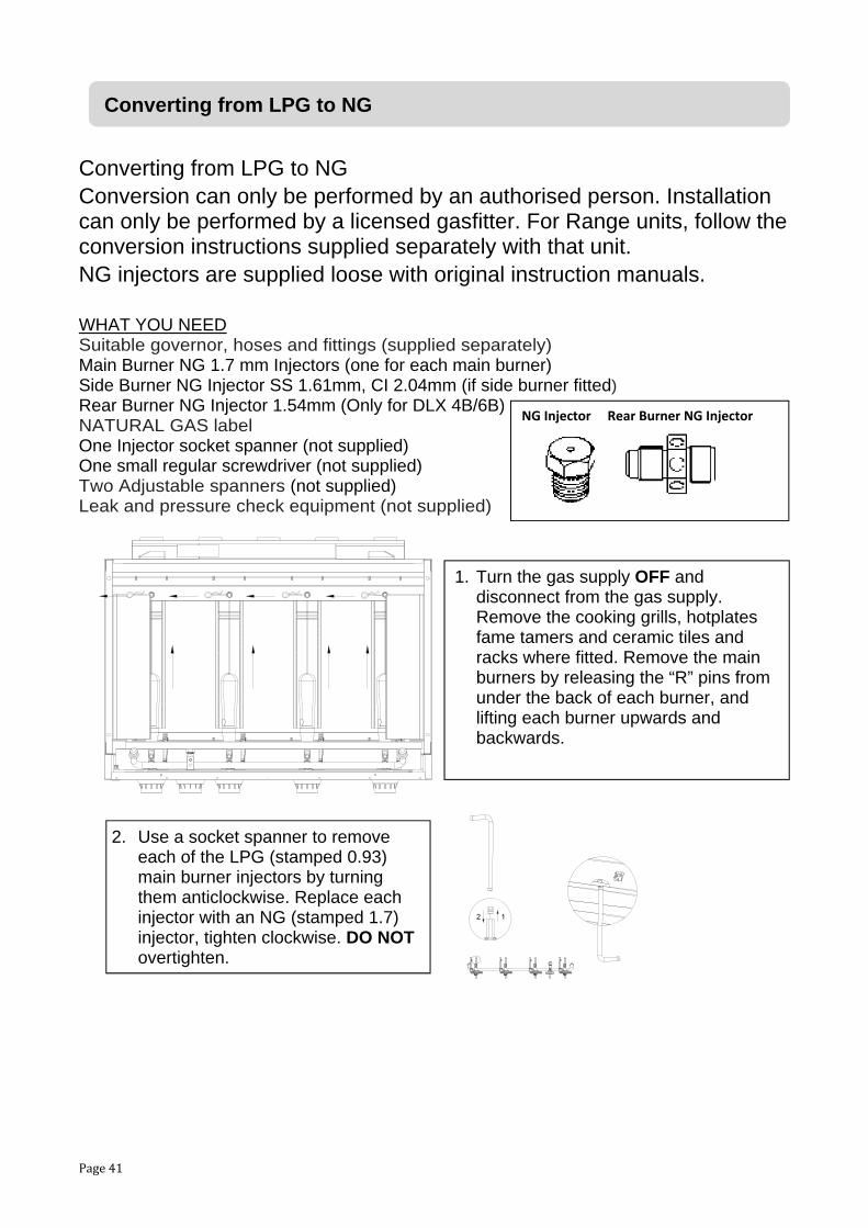
Converting from LPG to NG Conversion can only be performed by an authorised person. Installation can only be performed by a licensed gasfitter. For Range units, follow the conversion instructions supplied separately with that unit. NG injectors are supplied loose with original instruction manuals. WHAT YOU NEED Suitable governor, hoses and fittings (supplied separately) Main Burner NG 1.7 mm Injectors (one for each main burner) Side Burner NG Injector SS 1.61mm, CI 2.04mm (if side burner fitted) Rear Burner NG Injector 1.54mm (Only for DLX 4B/6B) NATURAL GAS label One Injector socket spanner (not supplied) One small regular screwdriver (not supplied) Two Adjustable spanners (not supplied) Leak and pressure check equipment (not supplied)
12
Converting from LPG to NG
NG Injector Rear Burner NG Injector
1. Turn the gas supply OFF and disconnect from the gas supply. Remove the cooking grills, hotplates fame tamers and ceramic tiles and racks where fitted. Remove the main burners by releasing the “R” pins from under the back of each burner, and lifting each burner upwards and backwards.
2. Use a socket spanner to remove each of the LPG (stamped 0.93) main burner injectors by turning them anticlockwise. Replace each injector with an NG (stamped 1.7) injector, tighten clockwise. DO NOT overtighten.

Page 42
a
cb
3. Reinstall the main burners making sure that each burner is properly engaged onto the valve as shown.
4. a. Take off the main burner control knobs (leave the rear burner control knob as is). b. Locate each main burner low flame screw and adjust for NG by turning it anticlockwise two full turns (720°). (For reference, the LPG low flame position is 720° anticlockwise from the clockwise full stop position. The NG low flame position is 1440° anticlockwise from the clockwise full stop position). c. Replace the main burner control knobs.
5. Where a rear burner is fitted, detach the rear burner cover by removing the fixing screws from inside the hood as shown.
Converting from LPG to NG (continued)

Page 43
6. Using two spanners, one to hold the fitting, the other to turn the nut, loosen and disconnect the locking nut that fixes the rear burner injector in place. Unscrew the LPG injector (stamped 0.93) anticlockwise and replace with the NG injector (stamped 1.54). Using two spanners, replace and tighten the locknut.
7. Leak test the rear burner connections before replacing the rear burner cover. Refer to the Safety Leak Testing guide in this manual.
8. Where a side burner is fitted, open the lid and remove the trivet. Undo the screws holding the burner in place. Take care for the CI burner not to drop it once the support bracket is loosened.
9. Use a socket spanner to remove the LPG (stamped 0.96 for SS; stamped 1.24 for CI) side burner injector by turning it anticlockwise. Replace the LPG injector with an NG injector (stamped1.61 for SS; stamped 2.04 for CI) tighten clockwise with the socket spanner, DO NOT overtighten.
12
Converting from LPG to NG (continued)

Page 44
10.Replace the side burner. Make sure that the side burner is properly engaged onto the valve as shown.
11.a. Take off the side burner control knob. b. Locate the side burner low flame screw and adjust for NG by turning it: SS side burner: anticlockwise two full turns (720°). (For reference, the LPG low flame position is 120° anticlockwise from the clockwise full stop position. The NG low flame position is 840° anticlockwise from the clockwise full stop position.) CI side burner: anticlockwise two full turns (720°). (For reference, the LPG low flame position is 210° anticlockwise from the clockwise full stop position. The NG low flame position is 930° anticlockwise from the clockwise full stop position.) c. Replace the side burner control knob.
MCDXBSBSHELFV CI Side Burner MCBSBSHELFV SS Side Burner
a
cb
Converting from LPG to NG (continued)

Page 45
Conversion can only be performed by an authorised person. Installation can only be performed by a licensed gas fitter, a compliance certificate must be issued. For Range units, follow the conversion instructions supplied separately with that unit.
12.Using two spanners, remove the LPG hose and regulator assembly, and attach the NG gas connection. Note that the manifold connections are ½” BSP fittings. If your gasfitter is connecting direct to the gas supply with appropriate fittings not using a bayonet, then a NG Regulator (RCV250Q) must be fitted to each appliance. For bayonet connections, use separately supplied NGCK250VJQ which includes NG governor.
13.Affix the NATURAL GAS label to the Barbeque and any side burners in place of the previous UNIVERSAL LPG label. Check that all new injectors match the compliance plate data. Conduct a full leak test. Conduct a pressure check test with half the burners in use. Conduct a performance test in particular to check the low flame settings on the main burners and adjust where necessary so that the flames do not blow out too easily on low settings. Ensure the owner / users are aware of the new gas type and how to operate the appliance. Check the installation meets AS5601 and issue a compliance certificate to the owner.
14.Reinstall the flame tamers, ceramic tiles and racks, cooking grills and hotplates.
Converting from LPG to NG (continued)
BROMIC MF15 (1/2”) Female x Male BSP Connections AGA certificate 7425
BROMIC SS hose assembly 13mm ID 1500 mm AGA certificate 5497
BROMIC, Model No. 980L NG Governor AGA certificate 5862
Type 1 connector (Bayonet connector)
BROMIC SS hose assembly 13mm ID 300 mm AGA certificate 5497

Page 46
Cleaning your barbeque Your barbeque will look better and last longer if you keep it clean. Follow these simple steps. Take care to keep any electrical connections clean and dry. Switch OFF and disconnect from the power while cleaning. The cooking surfaces While the cooking surfaces are still hot, take a long-handled brush and a scraper brush and remove remaining oil and food scraps. Use an oven mitt to avoid burning yourself. Remove the cooking surfaces as required for a more thorough clean. The cast iron has a very tough vitreous enamel finish to protect from rust. It is OK to use rough brushes on this, but avoid sharp objects and harsh impacts. Avoid caustic cleansers. Rinse and dry thoroughly after cleaning or before use. The burners Occasionally the burner holes may get clogged with grease and food particles. Leaving the burners on for a maximum of 5 minutes with the hood open after you’ve finished cooking will burn off most of this. However, you should check the burners periodically for any sort of blockage. In particular, you should ensure that the aeration vents are free of insect nests and spider webs. To clean the burners, let them cool down, then remove and inspect them. If any of the holes are clogged, gently tap the burner onto a hard surface to remove residue. Use a wire brush to unclog the holes. Then lightly coat the burners with canola oil for ongoing protection. The flame thrower ignitions Occasionally these can be blocked by grease or insect webs. Clean with a cotton bud or similar. If the flame thrower injector hole itself is blocked, clean with a fine wire. Check the flame thrower arm is properly aligned and the support claw is not blocking the gas flow. The barbeque firebox and hood Grease can build up on the body of the barbeque firebox and hood. Simply clean it off with hot water and detergent. Do not use harsh oven cleaners as these will damage the surface coating. Stainless steel requires extra care. See the notes below. The grease channeling tray You must keep the fat channeling tray clean to prevent a build-up of grease. If you don’t do this, a fat fire can result. A fat fire can be quite dangerous, and will void the warranty on your barbeque. If your barbeque has a grease cup, change the fat absorbent material and clean or replace the disposable tray regularly. Other exterior surfaces Wash as necessary with hot water and detergent, rinse and dry. As surfaces age, a light coating of oil will restore lustre and help to slow deterioration from the elements. Use a cover to extend the life of the finish. Check suitability with the supplier before using any harsh cleansers. Try unknown cleansers or detergents on a small unexposed section before using everywhere.
Care and maintenance

Page 47
How to care for stainless steel Even though stainless steel is remarkably resistant to tarnish and rust relative to ordinary steels, it still needs proper care to avoid corrosion. Corrosion of stainless steel is not warranted as it is dependent on the care and maintenance of the product. If your barbeque is positioned in a more corrosive environment (e.g. near sea air), it will need more attention to care and maintenance to avoid corrosion. We recommend the following: • After use, clean the stainless steel surfaces with fresh water and a soft cloth. This quick
and simple task will make a big difference.
• Where light cleaning is needed, a commercially available stainless steel cleaner with a soft cloth should be used.
• To repair minor tea staining or pitting, you can use a light, non-metallic scour pad. It is important that you rub gently in line with the natural grain of the stainless steel surface to avoid leaving visible scratch marks.
• Use 3M stainless steel cleaner available for your local Barbeques Galore store to polish and protect all stainless steel surfaces. Follow the manufacturer's instructions on the can. Do not use while the barbeque is on or still hot! This will provide a temporary protective film on the stainless steel.
• Between uses, it is a good idea to leave the barbeque covered to prevent dust and air borne salts settling on the stainless steel surfaces. If left for too long, these particles can act as rust centres. Use a ventilated cover, or add a couple of sponges between the cover and the barbeque to promote ventilation and reduce condensation.
With a small amount of care, your investment in quality stainless steel will keep its beautiful finish as well as its value for a long time to come.
Storing Your Barbeque Your barbeque is designed to be used outdoors. However, just like a car, you will prolong the life of the appliance if you store it out of direct exposure to the elements when not in use. This can be done in many ways as below. Always shut OFF the gas supply and turn the Barbeque control valves to OFF when the unit is not in use. • Place a waterproof cover over it. These are available from most barbeque retailers. Use
a ventilated cover, or add a couple of sponges between the cover and the barbeque to promote ventilation and reduce condensation.
• Move the barbeque to a covered location. If you are storing it in a closed room (e.g. a shed or a garage) then disconnect and keep the cylinder outdoors and away from any other cylinders or any cars, boats, motorcycles or any other petrol engines.
• If you don’t intend to use it for a few months, lightly spray all surfaces with canola oil. This will help protect against corrosion.
Care and maintenance (continued)

Page 48
Servicing Your Barbeque • Apart from cleaning, your barbeque is a fairly low maintenance item. A couple of things
are worth looking at though. Remember to turn off and disconnect the gas before any maintenance is carried out.
• If your barbeque uses a flexible hose to connect to the gas, check the rubber O-ring on the regulator end of the hose assembly at least once a year. If it appears worn or cracked, have it replaced.
• We recommend having your barbeque checked by an authorised service agent every 5 years. This is to ensure there are no leaks and that all components are still functioning correctly.
• If you use a portable LPG gas cylinder, you will need to have the cylinder serviced or replaced every ten years. The date of the last service should be stamped on the neck of the bottle.
• As you can see, it’s easy to keep your barbeque in great shape so it can give you years of trouble free enjoyment.
Replacing the hose If there are any signs of wear or cracking in the barbeque hose(s), you need to replace them immediately. Ensure you replace only with the correct hose and regulator purchased from Barbeque Galore to ensure proper gas connection compatibility. We recommend replacing the hose and regulator every 5 years. Connect the nut of the hose to the same gas inlet of the barbeque that the old one was connected. Use two spanners to tighten it properly, one to hold the inlet, one to turn the hose nut. Do not use sealing tape. The connection is designed to seal properly without it. Perform a leak test as explained in “Safety Leak Testing” section before use. Replace the hose and regulator at least every 5 years. Replacing the main burners Occasionally you will need to remove your main burners for cleaning, adjustment or replacement. Only use correct replacement parts available from your local Barbeques Galore store. To replace the burner, place the open end of the burner over the gas jet at the front of the barbeque. Then, lower the lug on the other end of the barbeque into the locating hole. Lock the burner in place at the back base with a “R” split pin through the lug at the back base of the burner.
Extending the life of the lights Bulbs and LEDs have limited life. Avoid unnecessary use to maximise lifespan. Keep connections dry and clean. Cover the bbq when it is not in use. Remove the batteries when the unit will not be used for extended periods.
Care and maintenance (continued)

Page 49
Problem Possible Cause Prevention/ Solution
Burner will not light No gas flow Obstructed gas flow Burner not over the valve Spider webs in the burner Burner ports blocked Flame ignition port blocked Flame ignition dirty / blocked
Check cylinder contents – refill Check burners and hose Engage burner over the valve Clean the burners Clean the burner ports Clean with a pin. Check claw bracket. Clean with a cotton bud.
Sudden drop in gas flow or reduced flame height
Out of gas Check supply / cylinder
Irregular flame pattern or flame does not run full length of burner
Burner ports blocked Burner old and deteriorated Burner not over the valve
Clean burner ports Replace burner Engage the burner onto the valve
Flame yellow or orange Residue on burner Spider webs in burner Burner not over the valve
Burn clean for 10 minutes on HI Clean burner ports and interior Engage the burner onto the valve
Flame blows out in wind gusts
Too windy Low on gas Excess grease build-up
Shelter or move the bbq Replace or refill the cylinder Clean the bbq, especially the burners
Persistent grease fire Grease trapped by food build-up around the burner and grease channeling system
Turn burners OFF. Turn gas OFF. Leave hood closed and let the fire burn out. Once cooled, remove and clean all parts. Keep bbq clean to avoid issue.
Blowback (fire burning inside the burner)
Burner and or burner tubes may be blocked
Switch OFF and re-light. If problem persists, remove and clean the burners.
Inside of hood peeling like paint
Baked on smoky grease build up has carbonised and is flaking
Clean inside of hood thoroughly to resolve. Clean inside of bbq regularly to avoid.
Knob lights not working Control panels lights out Halogen lights out Light failures
Flat battery Power off Power off Bulbs / LEDs worn out
Check and change batteries Check power supply and connections Check power supply and connections Replace bulbs / LEDs
If a service is required for your barbeque, contact your local Barbeque Galore store Phone 1 800 978 555 For customer care call 1 300 301 392. Or visit us online at www.barbequesgalore.com.au
Troubleshooting guide

Page 50
G2BV
23
568
11
4 101213
14
15
16
17
181920
2122
24
2526
28
29
3035
31
3233
34
36
37
2723
1
79
No. Code Description No. Code Description 1 CP9156451 Hood 20 CP9156464 Grease Channeling Tray 2 CP9156452 Thermometer Bezel 21 CP9156465 Knob 3 CP9156453 Thermometer 22 CP9156428 Knob Bezel 4 CP9156454 Left handle Bezel 23 CP9156466 Burner 5 CP9156455 Right handle Bezel 24 CP9156467 Rear Panel 6 CP9156456 Handle 25 CP9156468 CI Grill 7 CP9156457 Hood Rotary Shaft 26 CP9095274 CI Hotplate 8 CP9156548 Washer 27 CP9156469 Flame Tamer 9 CP9156466 R Pin 28 CP9156470 Left Side Panel 10 CP9156458 Warming Rack 29 CP9156471 Right Side Panel 11 CP9094149 R Pin 30 CP9095304 Regulator 12 CP9156459 Hood Back Support 31 CP9156472 Roof Panel 13 CP9156460 Hood Left Support 32 CP9156432 Grease Channeling Tray Bracket 14 CP9156461 Hood Right Support 33 CP9156473 Grease Tray 15 CP9156462 Furnace 34 CP9156473 Grease Channeling Tray Handle 16 CP9094260 Washer 35 CP9156474 Valve Assembly 17 CP9156463 Control Panel 36 CP9095756 Roof Panel Silicone Sleeve 18 CP9095519 Connector 37 CP9156475 Bolt Pack 19 CP9156462 Heat insulation
Spare Parts

Page 51
G2PBV
1
23
45 6
89
10
11
13
7
141516
17
18
19
20
212223
2425
26
27
2829
31
32
33
12
40
34
3536
37
38
39
41
30
No. Code Description No. Code Description 1 CP9156476 Hood 23 CP9156464 Grease Channeling Tray 2 CP9156452 Thermometer Bezel 24 CP9156429 LED Knob 3 CP9156477 Thermometer Fixed 25 CP9156428 Knob Bezel 4 CP9156453 Thermometer 26 CP9095512 CI Burner 5 CP9156478 Glass 27 CP9156467 Rear Panel 6 CP9156479 Glass Bracket 28 CP9156481 CI Grill 7 CP9156454 Left handle Bezel 29 CP9095274 CI Hotplate 8 CP9156455 Right handle Bezel 30 CP9156469 Flame Tamer 9 CP9156456 Handle 31 CP9095514 Left Side Panel 10 CP9156457 Hood Rotary Shaft 32 CP9095554 Right Side Panel 11 CP9156548 Washer 33 CP9095304 Regulator 12 CP9156466 R Pin 34 CP9156472 Roof Panel 13 CP9094149 R Pin 35 CP9156432 Grease Channeling Tray Bracket 14 CP9156458 Warming Rack 36 CP9156473 Grease Tray 15 CP9156459 Hood Back Support 37 CP9156473 Grease Channeling Tray Handle 16 CP9156460 Hood Left Support 38 CP9095756 Roof Panel Silicone Sleeve 17 CP9156461 Hood Right Support 39 CP9156490 Hood Cushion Rubber 18 CP9156462 Furnace 40 CP9156474 Valve Assembly 19 CP9094260 Washer 41 CP9156475 Bolt Pack 20 CP9156480 Control Panel 21 CP9095519 Connector 22 CP9156462 Heat insulation
Spare parts (continued)

Page 52
G2DXBV
1
23
45 6
89
10
11
13
7
141516
1718
19
20
2122
2324
2526
272829
3031
32
33
3435
3736
38
39
40
12
41
42
4344
45
464847+
12
49
50
51
52
5354
Spare parts (continued)

Page 53
G2DXBV
No. Code Description No. Code Description 1 CP9156482 Hood 28 CP9156462 Heat insulation 2 CP9156452 Thermometer Bezel 29 CP9156464 Grease Channeling Tray 3 CP9156477 Thermometer Fixed 30 CP9156429 LED Knob 4 CP9156453 Thermometer 31 CP9156428 Knob Bezel 5 CP9156478 Glass 32 CP9095512 CI Burner 6 CP9156479 Glass Bracket 33 CP9156467 Rear Panel 7 CP9156454 Left handle Bezel 34 CP9156481 CI Grill 8 CP9156455 Right handle Bezel 35 CP9095274 CI Hotplate 9 CP9156456 Handle 36 CP9156491 Ceramic Flame Tamer Bracket 10 CP9156457 Hood Rotary Shaft 37 CP9152832 Ceramic Flame Tamer 11 CP9156548 Washer 38 CP9095514 Left Side Panel 12 CP9156466 R Pin 39 CP9095554 Right Side Panel 13 CP9094149 R Pin 40 CP9095304 Regulator 14 CP9156458 Warming Rack 41 CP9156474 Valve Assembly 15 CP9156483 Hood Back Support 42 CP9156472 Roof Panel 16 CP9156460 Hood Left Support 43 CP9156432 Grease Channeling Tray Bracket 17 CP9156461 Hood Right Support 44 CP9156473 Grease Tray 18 CP9156484 Rear cover hood 45 CP9156473 Grease Channeling Tray Handle 19 CP9156462 Furnace 46 CP9095756 Roof Panel Silicone Sleeve 20 CP9094260 Washer 47 CP9156492 AC / DC Transformer 21 CP9156485 Control Panel 48 CP9156492 Transformer Bracket 22 CP9156486 Tempered glass 49 CP9156493 Output Wire 23 CP9156487 Control Panel Fixed Panel 50 CP9095303 Rear Panel Light 24 CP9156488 switch 51 CP9156462 Fixed Ring 25 CP9156489 PCB Panel 52 CP9156490 Hood Cushion Rubber 26 CP9156489 PCB Fixed Plate 53 CP9156474 Glass Drill Pipe 27 CP9095519 Connector 54 CP9156494 Bolt Pack
Spare parts (continued)

Page 54
G4BV
1 9 7 3 2 5
46812
13
10
1519
17
1125
26
14
2221
292016
1823
24
28
30
32 33
343536
37
39 38 31
27
No. Code Description No. Code Description 1 CP9156495 Hood 21 CP9156465 Knob 2 CP9156452 Thermometer Bezel 22 CP9156428 Knob Bezel 3 CP9156453 Thermometer 23 CP9156466 Burner 4 CP9156454 Left handle Bezel 24 CP9095567 Rear Panel 5 CP9156455 Right handle Bezel 25 CP9156501 CI Grill 6 CP9156456 Handle 26 CP9095755 CI Hotplate 7 CP9156457 Hood Rotary Shaft 27 CP9156469 Flame Tamer 8 CP9156548 Washer 28 CP9156470 Left Side Panel 9 CP9156466 R Pin 29 CP9156471 Right Side Panel 10 CP9094149 R Pin 30 CP9095304 Regulator 11 CP9156497 Warming Rack 31 CP9156431 Roof Panel 12 CP9156498 Hood Back Support 32 CP9156502 Grease Channeling Tray 13 CP9156460 Hood Left Support 33 CP9094785 Foil Tray 14 CP9156461 Hood Right Support 34 CP9156432 Grease Channeling Tray Bracket 15 CP9156499 Furnace 35 CP9156433 Grease Tray 16 CP9094260 Washer 36 CP9156433 Grease Channeling Tray Handle 17 CP9156500 Control Panel 37 CP9156503 Valve Assembly 18 CP9095519 Connector 38 CP9095756 Roof Panel Silicone Sleeve 19 CP9156499 Heat insulation 39 CP9156504 Bolt Pack 20 CP9156464 Grease Channeling Tray
Spare parts (continued)
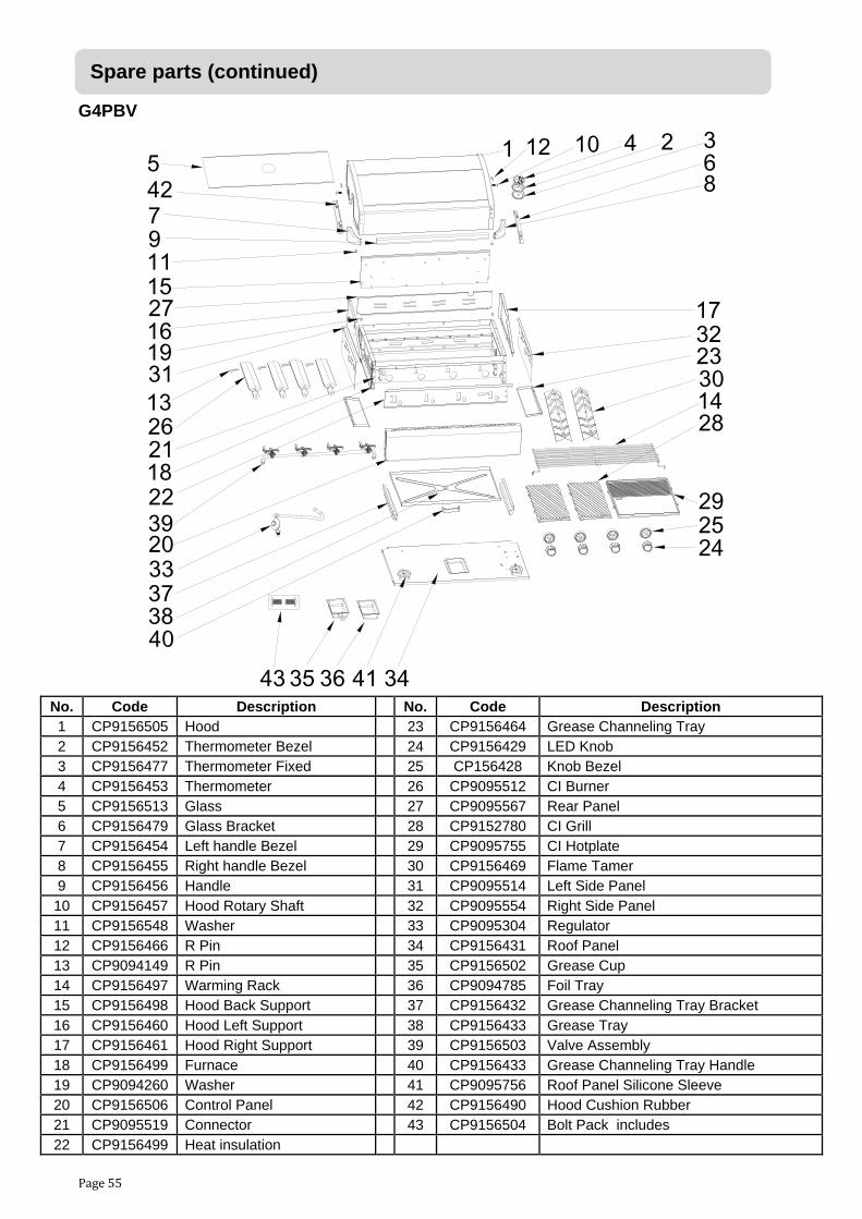
Page 55
G4PBV
1 12 10 4 2 365
78
91115
16
13
1822
20
1428
29
17
2524
322319
2126
27
31
33
35 36
373840
39
43
42
41 34
30
No. Code Description No. Code Description 1 CP9156505 Hood 23 CP9156464 Grease Channeling Tray 2 CP9156452 Thermometer Bezel 24 CP9156429 LED Knob 3 CP9156477 Thermometer Fixed 25 CP156428 Knob Bezel 4 CP9156453 Thermometer 26 CP9095512 CI Burner 5 CP9156513 Glass 27 CP9095567 Rear Panel 6 CP9156479 Glass Bracket 28 CP9152780 CI Grill 7 CP9156454 Left handle Bezel 29 CP9095755 CI Hotplate 8 CP9156455 Right handle Bezel 30 CP9156469 Flame Tamer 9 CP9156456 Handle 31 CP9095514 Left Side Panel 10 CP9156457 Hood Rotary Shaft 32 CP9095554 Right Side Panel 11 CP9156548 Washer 33 CP9095304 Regulator 12 CP9156466 R Pin 34 CP9156431 Roof Panel 13 CP9094149 R Pin 35 CP9156502 Grease Cup 14 CP9156497 Warming Rack 36 CP9094785 Foil Tray 15 CP9156498 Hood Back Support 37 CP9156432 Grease Channeling Tray Bracket 16 CP9156460 Hood Left Support 38 CP9156433 Grease Tray 17 CP9156461 Hood Right Support 39 CP9156503 Valve Assembly 18 CP9156499 Furnace 40 CP9156433 Grease Channeling Tray Handle 19 CP9094260 Washer 41 CP9095756 Roof Panel Silicone Sleeve 20 CP9156506 Control Panel 42 CP9156490 Hood Cushion Rubber 21 CP9095519 Connector 43 CP9156504 Bolt Pack includes 22 CP9156499 Heat insulation
Spare parts (continued)

Page 56
G4DXBV
+
12
1 12 10 4238
57
691118
15
16
13
19
28232122252650
143435
17
3130
392924
41
20
2732
33
3637
38
40
42 43 5847 47 48
51
52
5354
55
56
57
59 60 61
62
444546 636566
64
7071
69
736867
72
Spare parts (continued)

Page 57
G4DXBV
No. Code Description No. Code Description 1 CP9156507 Hood 39 CP9095554 Right Side Panel 2 CP9156452 Thermometer Bezel 40 CP9095304 Regulator 3 CP9156477 Thermometer Fixed 41 CP9156431 Roof Panel 4 CP9156453 Thermometer 42 CP9156502 Grease Channeling Tray Bracket 5 CP9156513 Glass 43 CP9094785 Foil Tray 6 CP9156479 Glass Bracket 44 CP9156432 Grease Channeling Tray Bracket 7 CP9156454 Left handle Bezel 45 CP9156433 Grease Tray 8 CP9156455 Right handle Bezel 46 CP9156433 Grease Channeling Tray Handle 9 CP9156496 Handle 47 CP9095756 Roof Panel Silicone Sleeve 10 CP9156457 Hood Rotary Shaft 48 CP9156492 AC / DC Transformer 11 CP9156548 Washer 49 CP9156492 Transformer Bracket 12 CP9156466 R Pin 50 CP9156515 Output Wire 13 CP9094149 R Pin 51 CP9095303 Rear Panel Light 14 CP9156497 Warming Rack 52 CP9156516 Injector 15 CP9156508 Hood Back Support 53 CP9156517 Thermocouple 16 CP9156460 Hood Left Support 54 CP9156518 Rear burner ignition 17 CP9156461 Hood Right Support 55 CP9155202 Infrared rear burner assembly 18 CP9095563 Rear cover hood 56 CP9156519 Rear furnace bellows 19 CP9156499 Furnace 57 CP9156518 ignition pin box 20 CP9094260 Washer 58 CP9156520 Pulse igniter assembly 21 CP9156509 Control Panel 59 CP9156520 Left rail of pulse rail 22 CP9156510 Tempered glass 60 CP9156520 Right rail of pulse rail 23 CP9156511 Control Panel Fixed Panel 61 CP9156520 Firearm Line Group 24 CP9156488 switch 62 CP9156520 Back burner ignition line 25 CP9156512 PCB Panel 63 CP9156521 Motor Bracket 26 CP9156512 PCB Fixed Plate 64 CP9156521 Rotisserie Kit 27 CP9095519 Connector 65 CP9156521 Pulse Unit 28 CP9156499 Heat insulation 66 CP9156521 AC / DC Transformer 29 CP9156464 Grease Channelling Tray 67 CP9156515 Fiberglass tubeφ8 30 CP9156429 LED Knob 68 CP9156515 Fiberglass tubeφ22 31 CP9156428 Knob Bezel 69 CP9156519 Rear burner hose retainer 32 CP9095512 CI Burner 70 CP9156499 Fixed Ring 33 CP9095567 Rear Panel 71 CP9156522 Valve Assembly 34 CP9152780 CI Grill 72 CP9156490 Hood Cushion Rubber 35 CP9095755 CI Hotplate 73 CP9156523 Bolt Pack 36 CP9156514 Ceramic Flame Tamer Bracket 37 CP9152832 Ceramic Flame Tamer 38 CP9095514 Left Side Panel
Spare parts (continued)

Page 58
G6BV
1 9 7 3 2 5
46812
13
10
1519
17
1125
26
14
2221
2920
16
18
23
24
28
30
32 33
343536
37
39 38 31
27
No. Code Description No. Code Description 1 CP9156524 Hood 21 CP9156465 Knob 2 CP9156452 Thermometer Bezel 22 CP9156428 Knob Bezel 3 CP9156453 Thermometer 23 CP9156466 Burner 4 CP9156454 Left handle Bezel 24 CP9156530 Rear Panel 5 CP9156455 Right handle Bezel 25 CP9156531 CI Grill 6 CP9156525 Handle 26 CP9156532 CI Hotplate 7 CP9156457 Hood Rotary Shaft 27 CP9156469 Flame Tamer 8 CP9156548 Washer 28 CP9156470 Left Side Panel 9 CP9156466 R Pin 29 CP9156471 Right Side Panel 10 CP9094149 R Pin 30 CP9095304 Regulator 11 CP9156526 Warming Rack 31 CP9156533 Roof Panel 12 CP9156527 Hood Back Support 32 CP9156502 Grease Channeling Tray 13 CP9156460 Hood Left Support 33 CP9094785 Foil Tray 14 CP9156461 Hood Right Support 34 CP9156432 Grease Channeling Tray Bracket 15 CP9156528 Furnace 35 CP9156534 Grease Tray 16 CP9094260 Washer 36 CP9156534 Grease Channeling Tray Handle 17 CP9156529 Control Panel 37 CP9156535 Valve Assembly 18 CP9095519 Connector 38 CP9095756 Roof Panel Silicone Sleeve 19 CP9156528 Heat insulation 39 CP9156536 Bolt Pack 20 CP9156464 Grease Channelling Tray
Spare parts (continued)

Page 59
G6PBV
1 12 10 42385
76
91115
16
1828
20
142829
17
2524
3223
19
22
27
31
33
35 36
373840
39
43
42
41 34
1326
30
No. Code Description No. Code Description 1 CP9156537 Hood 23 CP9156464 Grease Channeling Tray 2 CP9156452 Thermometer Bezel 24 CP9156429 LED Knob 3 CP9156477 Thermometer Fixed 25 CP9156428 Knob Bezel 4 CP9156453 Thermometer 26 CP9095512 CI Burner 5 CP9156538 Glass 27 CP9156530 Rear Panel 6 CP9156479 Glass Bracket 28 CP9156540 CI Grill 7 CP9156454 Left handle Bezel 29 CP9156532 CI Hotplate 8 CP9156455 Right handle Bezel 30 CP9156469 Flame Tamer 9 CP9156525 Handle 31 CP9095514 Left Side Panel 10 CP9156457 Hood Rotary Shaft 32 CP9095554 Right Side Panel 11 CP9156548 Washer 33 CP9095304 Regulator 12 CP9156466 R Pin 34 CP9156533 Roof Panel 13 CP9094149 R Pin 35 CP9156502 Grease Cup 14 CP9156526 Warming Rack 36 CP9094785 Foil Tray 15 CP9156527 Hood Back Support 37 CP9156432 Grease Channeling Tray Bracket 16 CP9156460 Hood Left Support 38 CP9156534 Grease Tray 17 CP9156461 Hood Right Support 39 CP9156535 Valve Assembly 18 CP9156528 Furnace 40 CP9156534 Grease Channeling Tray Handle 19 CP9094260 Washer 41 CP9095756 Roof Panel Silicone Sleeve 20 CP9156539 Control Panel 42 CP9156490 Hood Cushion Rubber 21 CP9095519 Connector 43 CP9156536 Bolt Pack 22 CP9156528 Heat insulation
Spare parts (continued)

Page 60
G6DXBV
+
12
1 12 10 4238
57
691118
15
16
13
19
28232122252650
143435
17
3130
392924
41
20
2732
3336
37
38
40
42 43 5847 47 48
51
52
5354
55
56
57
59 60 61
62
444546 636566
64
7071
69
736867
72
Spare parts (continued)

Page 61
G6DXBV
No. Code Description No. Code Description 1 CP9156542 Hood 39 CP9095554 Right Side Panel 2 CP9156452 Thermometer Bezel 40 CP9095304 Regulator 3 CP9156477 Thermometer Fixed 41 CP9156533 Roof Panel 4 CP9156453 Thermometer 42 CP9156502 Grease Channeling Tray Bracket 5 CP9156538 Glass 43 CP9094785 Foil Tray 6 CP9156479 Glass Bracket 44 CP9156432 Grease Channeling Tray Bracket 7 CP9156454 Left handle Bezel 45 CP9156534 Grease Tray 8 CP9156455 Right handle Bezel 46 CP9156534 Grease Channeling Tray Handle 9 CP9156525 Handle 47 CP9095756 Roof Panel Silicone Sleeve 10 CP9156457 Hood Rotary Shaft 48 CP9156492 AC / DC Transformer 11 CP9156548 Washer 49 CP9156492 Transformer Bracket 12 CP9156466 R Pin 50 CP9156550 Output Wire 13 CP9094149 R Pin 51 CP9095303 Rear Panel Light 14 CP9156526 Warming Rack 52 CP9156516 Injector 15 CP9156543 Hood Back Support 53 CP9156517 Thermocouple 16 CP9156460 Hood Left Support 54 CP9156518 Rear burner ignition 17 CP9156461 Hood Right Support 55 CP9155202 Infrared rear burner assembly 18 CP9095563 Rear cover hood 56 CP9156551 Rear furnace bellows 19 CP9156528 Furnace 57 CP9156518 ignition pin box 20 CP9094260 Washer 58 CP9156552 Pulse igniter assembly 21 CP9156544 Control Panel 59 CP9156552 Left rail of pulse rail 22 CP9156545 Tempered glass 60 CP9156552 Right rail of pulse rail 23 CP9156546 Control Panel Fixed Panel 61 CP9156552 Firearm Line Group 24 CP9156488 switch 62 CP9156552 Back burner ignition line 25 CP9156547 PCB Panel 63 CP9156553 Motor Bracket 26 CP9156547 PCB Fixed Plate 64 CP9156553 Rotisserie Kit 27 CP9095519 Connector 65 CP9156553 Pulse Unit 28 CP9156528 Heat insulation 66 CP9156553 AC / DC Transformer 29 CP9156464 Grease Channeling Tray 67 CP9156550 Fiberglass tubeφ8 30 CP916429 LED Knob 68 CP9156550 Fiberglass tubeφ22 31 CP9156428 Knob Bezel 69 CP9156551 Rear burner hose retainer 32 CP9095512 CI Burner 70 CP9156528 Fixed Ring 33 CP9156530 Rear Panel 71 CP9156554 Valve Assembly 34 CP9156540 CI Grill 72 CP9156490 Hood Cushion Rubber 35 CP9156532 CI Hotplate 73 CP9156555 Bolt Pack 36 CP9156549 Ceramic Flame Tamer Bracket 37 CP9152832 Ceramic Flame Tamer 38 CP9095514 Left Side Panel
Spare parts (continued)

Page 62
All dimensions in mm:
625
519
284
303
605
607
618
647 548
558
599
Technical details

Page 63
839
945
284
303605
634646
548647
878
919
1265
1159
284
303 605
634
646
548
647
1198
1239
Technical details (continued)

Page 64
519
1163
570
619
607
284
1177519
284
1163
607720
570
Technical details (continued)

Page 65
83928
4
1163
634646
839
1546
284
1163
720
634
Technical details (continued)

Page 66
1159
1163
284
634
646
11591865
284
1163
634
720
Technical details (continued)

Page 67
Technical details (continued)

Page 68
The gas connections are all ½” BSP thread.
472
564width
gas connection82mm from front (2B, 4B, 6B )
75mm from side (2B, 4B, 6B ) gas connection82mm from front (2B, 4B, 6B )
75mm from side (2B, 4B, 6B )
Technical details (continued)

Page 69
Anything you can cook in the kitchen and more, you can cook on a barbeque: soups, roasts, breads, casseroles, stir fries, pizza, chips, smoked foods, lasagna… are just a few of the possibilities. Optional accessories include: Gas Safety Gauge: Must have safety device. Shuts off gas quickly and completely in case of a sudden major leak. Use it to detect minor leaks quickly and thoroughly without fussing with soapy water. Weather Cover: Protect your investment with a cover that fits neatly over your barbeque to combat not only the sun and the rain but also tree sap, bird droppings and various backyard pests. Slide Out Drawer: Suits cart models as a drawer for your gas cylinder for much easier access to turn the cylinder on or off and when replacing the cylinder. Also can accept one or two storage racks as a utility drawer. Adjustable Storage Rack: Fits into the base panel of the cart or into the slide out drawer for easy access to all your bbq gadgets. Also can be used as an adjustable multi-level roast rack.
Need More Information? You can call your local Barbeques Galore store where barbeque experts will be happy to help you.
Phone 1 800 978 555 Or visit us online at: www.barbequesgalore.com.au
For customer care call 1300 301 392
Barbeques Galore G.L.G. Australia Pty Ltd (ABN 70 001 185 002)
Building A2, Campus Business Park, 350-374 Parramatta Road, Homebush, NSW 2140 AUSTRALIA
Phone 02 9735 4111 BeefmasterV-head-instruction-manual-july-2020
The next step