welcome to msc.visualnastran 4dbme2.aut.ac.ir/~towhidkhah/motorcontrol/resources/seminar...
TRANSCRIPT
MSC.Software Tel. 800.766.6615 Fax. 650.574.7541 http://www.vndesktop.com Created & last updated 2/17/2004 by Paul Mitiguy and Michael Woo
1
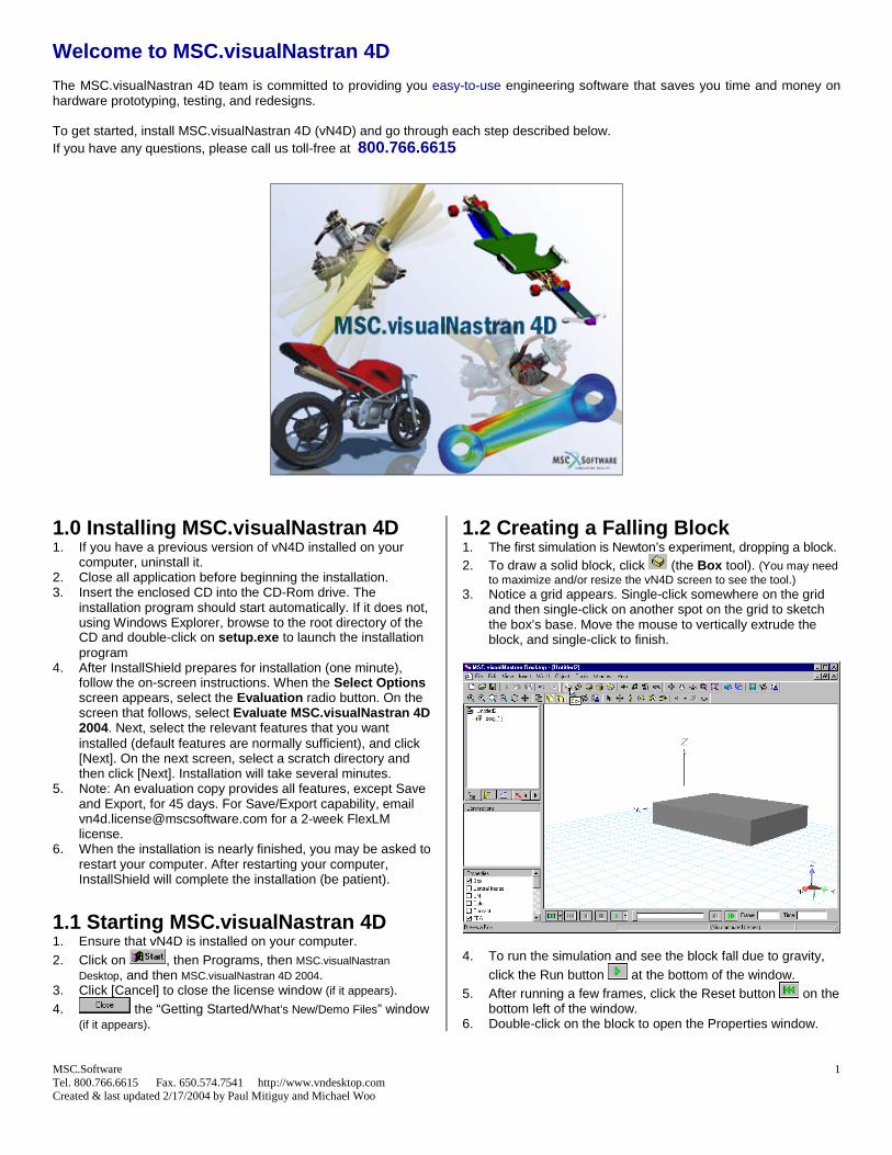
Welcome to MSC.visualNastran 4D The MSC.visualNastran 4D team is committed to providing you easy-to-use engineering software that saves you time and money on hardware prototyping, testing, and redesigns. To get started, install MSC.visualNastran 4D (vN4D) and go through each step described below. If you have any questions, please call us toll-free at 800.766.6615
1.0 Installing MSC.visualNastran 4D 1. If you have a previous version of vN4D installed on your
computer, uninstall it. 2. Close all application before beginning the installation. 3. Insert the enclosed CD into the CD-Rom drive. The
installation program should start automatically. If it does not, using Windows Explorer, browse to the root directory of the CD and double-click on setup.exe to launch the installation program
4. After InstallShield prepares for installation (one minute), follow the on-screen instructions. When the Select Options screen appears, select the Evaluation radio button. On the screen that follows, select Evaluate MSC.visualNastran 4D 2004. Next, select the relevant features that you want installed (default features are normally sufficient), and click [Next]. On the next screen, select a scratch directory and then click [Next]. Installation will take several minutes.
5. Note: An evaluation copy provides all features, except Save and Export, for 45 days. For Save/Export capability, email [email protected] for a 2-week FlexLM license.
6. When the installation is nearly finished, you may be asked to restart your computer. After restarting your computer, InstallShield will complete the installation (be patient).
1.1 Starting MSC.visualNastran 4D 1. Ensure that vN4D is installed on your computer. 2. Click on , then Programs, then MSC.visualNastran
Desktop, and then MSC.visualNastran 4D 2004. 3. Click [Cancel] to close the license window (if it appears). 4. the “Getting Started/What’s New/Demo Files” window
(if it appears).
1.2 Creating a Falling Block 1. The first simulation is Newton’s experiment, dropping a block. 2. To draw a solid block, click (the Box tool). (You may need
to maximize and/or resize the vN4D screen to see the tool.) 3. Notice a grid appears. Single-click somewhere on the grid
and then single-click on another spot on the grid to sketch the box’s base. Move the mouse to vertically extrude the block, and single-click to finish.
4. To run the simulation and see the block fall due to gravity,
click the Run button at the bottom of the window. 5. After running a few frames, click the Reset button on the
bottom left of the window. 6. Double-click on the block to open the Properties window.

2
7. In the Properties window, click on the Appearance tab and check the boxes for “Center of mass shown” and “Translucent”. Click on the color box to pick a color.
8. In the Properties window, click on the Pos tab and enter the
values indicated below.
9. In the Properties window, click on the Material tab and enter
the values indicated below
10. In the Properties window, click on the Box tab and enter the first three values indicated below
11. Click [Close] to close the Properties window. 12. To re-run the simulation, click the Run button . 13. After running a few frames, click to reset the simulation.
1.3 Making a Pendulum 1. Press “ f ” to look at the front view of the block. 2. Click on the workspace (the white background in the
window with the solid block) to de-select the block.
3. On the Create Constraint tool , click the down arrow , and select Revolute Joint (as shown in the next figure).
4. Click on the front surface of the block slightly below the
upper left hand corner and press [Enter].
5. To run the pendulum simulation, click the Run button . 6. Click to reset the simulation. 1.4 Graphing the Pendulum’s Motion 1. To graph the pendulum’s motion, click on the block. Choose
the Insert menu, select Meter, and then Orientation. 2. Click to run and then click to reset. 3. Optional: If you prefer to view numbers rather than graphs,
right-click on the graph and select Digital. Return to viewing graphs by right-clicking on the meter and select Graph.

3
1.5 Adding a Spring-Damper 1. Click on the workspace (not on the pendulum).
2. On the Create Constraint tool , click the down arrow , and select Linear Spring/Damper (as shown below).
3. Click on the upper right-hand corner of the block and then
click on the workspace above the first point, as shown below. 4. Click to run the simulation and then click to reset. 5. Notice the graph of the decaying oscillation.
1.6 Controlling the Spring Constant 1. With the spring selected, select the Insert menu, select
Control, and then select Spring Constant. Click [OK] to select the slider.
2. Click and observe that the motion of the pendulum is a function of the spring constant (slide the slider from left to right while the simulation is running).
3. Click to reset the simulation.
1.7 Importing a Cam vN4D can import CAD geometry from all major neutral formats, including ACIS, CATIA, Parasolids, STEP, IGES, and STL. 1. To import a cam into the simulation, choose the Insert
menu, select Body, and then Geometry… Click the vN Shortcuts button on the bottom left, double-click on the EvaluationKit folder and then open SampleCam.sat.
2. Enter the value of 1000 in the spring constant slider.
Optional: Click to hide the spring constant slider. 3. Click and observe the cam falling through the block. 4. Click to reset the simulation.
1.8 Collisions with Cam 1. To make the cam collide with the block, select the cam, then
hold down the [Ctrl] key while you click and select the block. Choose the Object menu, select Collide.
2. Click to run. Notice that vN4D does automatic contact detection and response, and the cam bounces and rolls off the block. Click to reset.
4
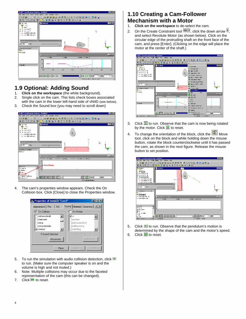
1.9 Optional: Adding Sound 1. Click on the workspace (the white background). 2. Single click on the cam. This lists check boxes associated
with the cam in the lower left-hand side of vN4D (see below). 3. Check the Sound box (you may need to scroll down)
4. The cam’s properties window appears. Check the On
Collision box. Click [Close] to close the Properties window.
5. To run the simulation with audio collision detection, click to run. (Make sure the computer speaker is on and the volume is high and not muted.)
6. Note: Multiple collisions may occur due to the faceted representation of the cam (this can be changed).
7. Click to reset.
1.10 Creating a Cam-Follower Mechanism with a Motor 1. Click on the workspace to de-select the cam.
2. On the Create Constraint tool , click the down arrow , and select Revolute Motor (as shown below). Click on the circular edge of the protruding shaft on the front face of the cam, and press [Enter]. (Clicking on the edge will place the motor at the center of the shaft.)
3. Click to run. Observe that the cam is now being rotated
by the motor. Click to reset.
4. To change the orientation of the block, click the Move tool, click on the block and while holding down the mouse button, rotate the block counterclockwise until it has passed the cam, as shown in the next figure. Release the mouse button to set position.
5. Click to run. Observe that the pendulum’s motion is
determined by the shape of the cam and the motor’s speed. 6. Click to reset.

5
7. To close the file, select the File menu and click Close. Do
not save changes. 8. Optional: To check that you constructed the simulation
properly, choose the File menu, select Open. Then click on the vN Shortcuts button on the left. Double-click on the EvaluationKit folder and double-click EvaluationKit.wm3. When you finish, select the File menu and click Close.
2.1 CAD Integration vN4D has associative integration with major CAD systems and performs motion and FEA analysis on parts and assemblies. To try CAD integration on a compressor, choose the File menu, select Open, and click on the vN Shortcuts button on the left. Double-click on the EvaluationKit folder and open the file PistonBegin.wm3, which contains a piston assembly imported from SolidWorks.
1. Press “ i ” to look at the isometric view of the assembly. 2. Click to run. Observe that after several seconds, the
piston assembly tumbles due to gravity. 3. Click to reset. Note: If you have a licensed version of vN4D and a CAD package, you may import the piston geometry as follows:
a. Inventor: Double-click on the InventorPiston folder and open the file PistonAssy.iam
b. Solid Edge: Double-click on the SolidEdgePiston folder and open the file PistonAssy.asm
c. SolidWorks: Double-click on the SolidWorksPiston folder and open the file PistonAssy.sldasm
2.2 Defining Part-to-Part Contact 1. To create contact between the piston head and the
connecting rod, select the PistonHead, and while holding down [Ctrl], select the ConnectingRod.
2. Choose the Object menu, select Collide.
3. Click to run. Notice that the motion is affected by the
contact between the parts. 4. Click to reset.
2.3 Motor-driven Crankshaft 1. At this point, the crankshaft rotates freely because it is
constrained by a revolute joint. To drive the piston, we will convert this revolute joint to a revolute motor. This revolute joint connects the crankshaft to the fixed part called Anchor-1 (see picture below).
2. Click on the word Anchor-1 to see the revolute joint appear in the Connections window (see picture). The revolute joint is identified by a green circular symbol .
3. Right-click on this revolute joint in the Connections window and select Properties. Choose the Constraint tab, scroll down to Revolute Motor and select it.
4. Choose the Appearance tab and rename the constraint Crank1Constraint (if necessary). Press [Close].

6
5. Click to run. Notice the crankshaft is moving at a
constant angular velocity. 6. Click to reset.
2.4 Creating a Vertical Slot Joint 1. To complete the model, the piston head’s motion needs to
be confined to a vertical slot (cylinder). 2. Click on the workspace to de-select all components.
3. On the Create Constraint tool , click the down arrow , and select Revolute Joint on Slot, as shown below.
4. Click on the top face of the piston head, and press [Enter].
5. Click and observe the motion of the piston assembly. 6. Click to reset.
2.5 Measuring Motor Angular Velocity 1. To measure the angular velocity of the motor, click on
Crank1Constraint in the Components list. From the Insert menu, select Meter, and then Angular Velocity.
2. Click and observe the angular velocity of the motor. 3. Click to reset.
2.6 Changing Units 1. You can change various settings in vN4D, e.g., units,
number of digits, colors, etc. To change units, from the World menu, select Display Settings…
2. In the Settings dialog box, click on Units (under Display Settings) in the left pane.
3. Change the Unit System to “SI (degrees)” 4. Change the Rot. Vel. unit to “rpm” and click [Close].
2.7 Changing an Angular Velocity Motor to a Torque Motor 1. To change the default motor (an angular velocity motor) to a
torque motor, right-click on Crank1Constraint in the Component List and select Properties.
2. In the Properties window, navigate to the Motor tab, select the Torque radio button, set the value to 50, and click [Close].

7
3. Click and observe the choppy motion. 4. Click to reset.
2.8 Changing Display Rate 1. Notice that in the previous step, the piston rotates too
quickly and looks choppy. To smooth the simulation, select the World menu, select Simulation Settings…, click on Integration (in the left pane), change the Animation Frame Rate to 2000 /s, and click [Close].
2. Click and run the simulation until the Angular Velocity is
approximately 20,000 RPM. Click . 2.9 FEA and Factor of Safety 1. To perform FEA (Finite Element Analysis) on the connecting
rod, right-click on it, and select “Include in FEA” and make sure the simulation is at Frame 0 by clicking .
2. Click (Solve FEA button) on the bottom left of the vN4D
window. 3. Click [OK] to close the Redundant constraint warning. 4. Note the FEA results shown on the connecting rod and the
associated color legend on the left-hand side.
5. To see the factor of safety, right-click on the color legend,
and select Factor of Safety. The entire connecting rod and color legend are blue, signifying that it has a factor of safety higher than 1. At this speed, the rod is structurally sound.
6. Drag the Run Control Slider all the way to the right, click on
(Step Backward) and/or (Step Forward) to move the connecting rod to an approximately upright position.

8
7. Click (Solve FEA button) and notice that at the higher speed, the connecting rod no longer passes the factor of safety test and warnings are issued.
8. Click to close the warnings window.
2.10 Adding Shadows and Rendering In vN4D, it is simple to create photorealistic rendering. Exporting fully rendered images and movies (with shadows, reflection, spotlight, material, texture map, etc.) are just a few clicks away. 1. To create a photorealistic rendering of the piston, choose
the Tools menu and select Render…
2. In the Photorealistic Rendering window, click on the Preview Window button on the right-hand side.
3. Click [Close] to close the Photorealistic Rendering window. 4. Click to close the Rendering Preview window.
5. Select the File menu, click Close, do not save changes. 6. Optional: To check that you constructed this simulation
properly, choose the File menu, select Open. Then click on the vN Shortcuts button on the left. Double-click on the EvaluationKit folder and double-click PistonFinished.wm3.
3.1 Running Other Demo Files To try another vN4D simulation, click on the vN4D Help menu, click on Welcome, click on Demo Files, and select a .wm3 file.
To take a demo tour, go to the File menu, click New. Select the Tools menu and click on Demo Tour.
3.2 Creating a Movie You can create a movie from any vN4D simulation. Note: Movie-exports are disabled in evaluation versions. To purchase a licensed version, call 800.766.6615 To see a presentation-quality movie of a simulation, click on , then Programs, then MSC.visualNastran Desktop, and then click on the EvaluationKit folder. Double-click on vN4DPropellor.mpg
3.3 MATLAB/SimuLink Integration vN4D merges CAD, motion, FEA, and controls technologies in a single functional modeling system. The vN4D paradigm is:
Draw it. Move it. Break it. Control it. The vN4D MATLAB/SimuLink feature allows you to test integrated comprehensive control systems on detailed mechanical models with:
Accurate representations of physical parts, contact, collision, friction, and forces
Detailed representations of sensors, actuators, filters, etc., from the powerful MATLAB/SimuLink language
Create presentation-quality photorealistic movie To view a movie of a piston whose thermodynamics are
controlled by SimuLink, choose the File menu, select Open and click on the vN Shortcuts button on the left. Open the EvaluationKit folder, then the MatlabIntegration folder. Double-click on PistonMatlabIntegration.avi.
MSC.Software Tel. 800.766.6615 Fax. 650.574.7541 http://www.vndesktop.com Created & last updated 2/17/2004 by Paul Mitiguy and Michael Woo