webcontrol 32 programmable logic controller programming guide · programmable logic controller...
TRANSCRIPT
WebControl 32TM Programmable Logic
Controller Programming Guide
Version: 4.02.10
Hardware Version: 5.0.0, 6.0.0, 7.0.0
Firmware Version: 4.02.10
Firmware datastamp: 10/22/2015
Doc last modified: 10/26/2015

WebControl32TM PLC Programming Guide Version 04.02.10
Copyright(C) 2008-2013 CAI Networks, Inc. i
Table of Contents
1 Introduction .......................................................................................................... 2
1.1 Scope ............................................................................................................ 2
1.2 Table of Definitions ....................................................................................... 2
2 WebControlTM PLC Programming ........................................................................ 5
2.1 The Basics of PLC Programming ................................................................. 5
2.2 WebControlTM PLC Instructions .................................................................... 6
2.3 WebControlTM PLC I/O Identifiers .............................................................. 10
2.4 WebControl PLC Examples ........................................................................ 15
2.4.1 Example 1 Set Output based on condition .......................................... 16
2.4.2 Example 2: Flash TTL output ............................................................. 16
2.4.3 Example 3: Push Button Input Control Output ..................................... 17
2.4.4 Example 4: Send EMAIL ..................................................................... 17
2.4.5 Example 5, Parallel I/O ........................................................................ 18
2.4.6 Example 6, Sequential I/O ................................................................... 19
2.4.7 Example 7, Traffic Lights ..................................................................... 20
2.4.8 Example 8, Time based Control .......................................................... 22
2.4.9 Example 9, Battery Charger ................................................................ 24
2.4.10 Example 10, RFID reader and browser Control .................................. 25
2.4.11 Example 11, Bitwise Operation ........................................................... 26
2.4.12 Example 12, Angle Calculation ............................................................ 27
2.4.13 Example 13, Non-Blocking Delay ........................................................ 27
2.4.14 Example 14, WEBSET to get server reply ........................................... 27
2.4.15 Example 15, Server CGI Handles WEBSET ....................................... 28
2.4.16 Example 16, USB key SAVE and LOAD functions .............................. 29
2.4.17 Example 17, USB LCD Display and Push Kay functions .................... 30
2.4.18 Example 18, I2C PLC Programming ADS1115 ................................... 31
2.4.19 Example 19, PING another host in PLC .............................................. 32
3 WebControlTM PLC FAQ .................................................................................. 33
3.1 Login and Configuration .............................................................................. 33
3.2 Temperature Sensor Support ..................................................................... 33
3.3 Turn on/off TTL output from another programming language ..................... 34
3.4 Power Supply Requirement ........................................................................ 35
WebControl32TM PLC Programming Guide Version 04.02.10
Copyright(C) 2008-2013 CAI Networks, Inc. ii
1 Introduction This document provides an overview of the technical aspects of Programming
WebControl32TM PLC. The WebControl 32 PLC Programming Guide is is very smilar
to the WebControl PLC User Guide in chapter 6. Function, usage and syntax as well
as many examples are provided there to help you get started. The PLC version of
firmware provides greater flexibility in I/O control; but in return, expects user to learn
programming concepts and write an assembly like PLC program. A PLC program
has the ability to read write and compare values of the available inputs, outputs,
variables and timers. With a PLC program loaded and running, WebControlTM PLC
can operate on its own, without a network connection. The PLC programming
module and programming guide are provided for a learn-on-your own experience.
Assistance in writing or debugging PLC code is not provided as part of the regular
technical support for WebControlTM PLC configuration.
1.1 Scope
The scope of this document is to be a guide for programming the features provided
by WebControl 32TM. The reader is expected to be technically competent in all the
technical areas within this document, and is strongly advised to play with example
PLC programs and to write small test PLC program to test out each PLC command.
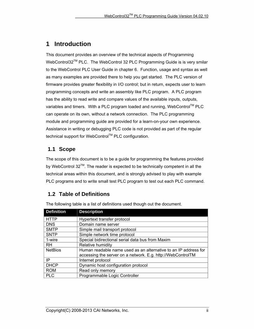
1.2 Table of Definitions
The following table is a list of definitions used though out the document.
Definition Description
HTTP Hypertext transfer protocol DNS Domain name server SMTP Simple mail transport protocol SNTP Simple network time protocol 1-wire Special bidirectional serial data bus from Maxim RH Relative humidity NetBios Human readable name used as an alternative to an IP address for
accessing the server on a network. E.g. http://WebControlTM IP Internet protocol DHCP Dynamic host configuration protocol ROM Read only memory PLC Programmable Logic Controller
WebControl32TM PLC Programming Guide Version 04.02.10
Copyright(c) 2008,-2015 CAI Networks, Inc. 5
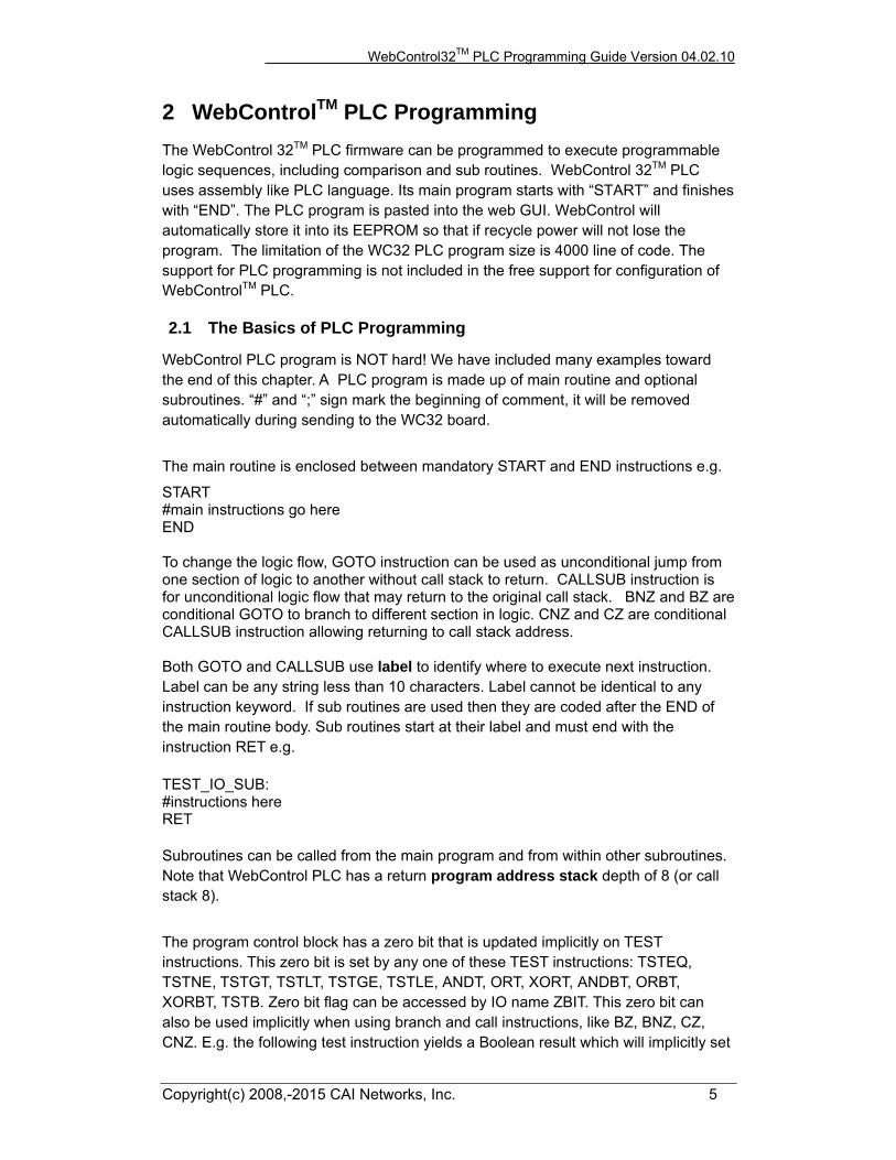
2 WebControlTM PLC Programming The WebControl 32TM PLC firmware can be programmed to execute programmable logic sequences, including comparison and sub routines. WebControl 32TM PLC uses assembly like PLC language. Its main program starts with “START” and finishes with “END”. The PLC program is pasted into the web GUI. WebControl will automatically store it into its EEPROM so that if recycle power will not lose the program. The limitation of the WC32 PLC program size is 4000 line of code. The support for PLC programming is not included in the free support for configuration of WebControlTM PLC.
2.1 The Basics of PLC Programming
WebControl PLC program is NOT hard! We have included many examples toward the end of this chapter. A PLC program is made up of main routine and optional subroutines. “#” and “;” sign mark the beginning of comment, it will be removed automatically during sending to the WC32 board.
The main routine is enclosed between mandatory START and END instructions e.g.
START #main instructions go here END To change the logic flow, GOTO instruction can be used as unconditional jump from one section of logic to another without call stack to return. CALLSUB instruction is for unconditional logic flow that may return to the original call stack. BNZ and BZ are conditional GOTO to branch to different section in logic. CNZ and CZ are conditional CALLSUB instruction allowing returning to call stack address. Both GOTO and CALLSUB use label to identify where to execute next instruction. Label can be any string less than 10 characters. Label cannot be identical to any instruction keyword. If sub routines are used then they are coded after the END of the main routine body. Sub routines start at their label and must end with the instruction RET e.g. TEST_IO_SUB: #instructions here RET Subroutines can be called from the main program and from within other subroutines. Note that WebControl PLC has a return program address stack depth of 8 (or call stack 8).
The program control block has a zero bit that is updated implicitly on TEST instructions. This zero bit is set by any one of these TEST instructions: TSTEQ, TSTNE, TSTGT, TSTLT, TSTGE, TSTLE, ANDT, ORT, XORT, ANDBT, ORBT, XORBT, TSTB. Zero bit flag can be accessed by IO name ZBIT. This zero bit can also be used implicitly when using branch and call instructions, like BZ, BNZ, CZ, CNZ. E.g. the following test instruction yields a Boolean result which will implicitly set
WebControl32TM PLC Programming Guide Version 04.02.10
Copyright(c) 2008,-2015 CAI Networks, Inc. 6
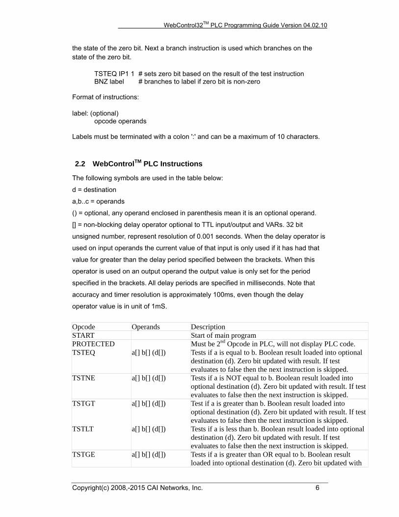
the state of the zero bit. Next a branch instruction is used which branches on the state of the zero bit. TSTEQ IP1 1 # sets zero bit based on the result of the test instruction BNZ label # branches to label if zero bit is non-zero Format of instructions: label: (optional) opcode operands Labels must be terminated with a colon ':' and can be a maximum of 10 characters.
2.2 WebControlTM PLC Instructions
The following symbols are used in the table below:
d = destination
a,b..c = operands
() = optional, any operand enclosed in parenthesis mean it is an optional operand.
[] = non-blocking delay operator optional to TTL input/output and VARs. 32 bit
unsigned number, represent resolution of 0.001 seconds. When the delay operator is
used on input operands the current value of that input is only used if it has had that
value for greater than the delay period specified between the brackets. When this
operator is used on an output operand the output value is only set for the period
specified in the brackets. All delay periods are specified in milliseconds. Note that
accuracy and timer resolution is approximately 100ms, even though the delay
operator value is in unit of 1mS.
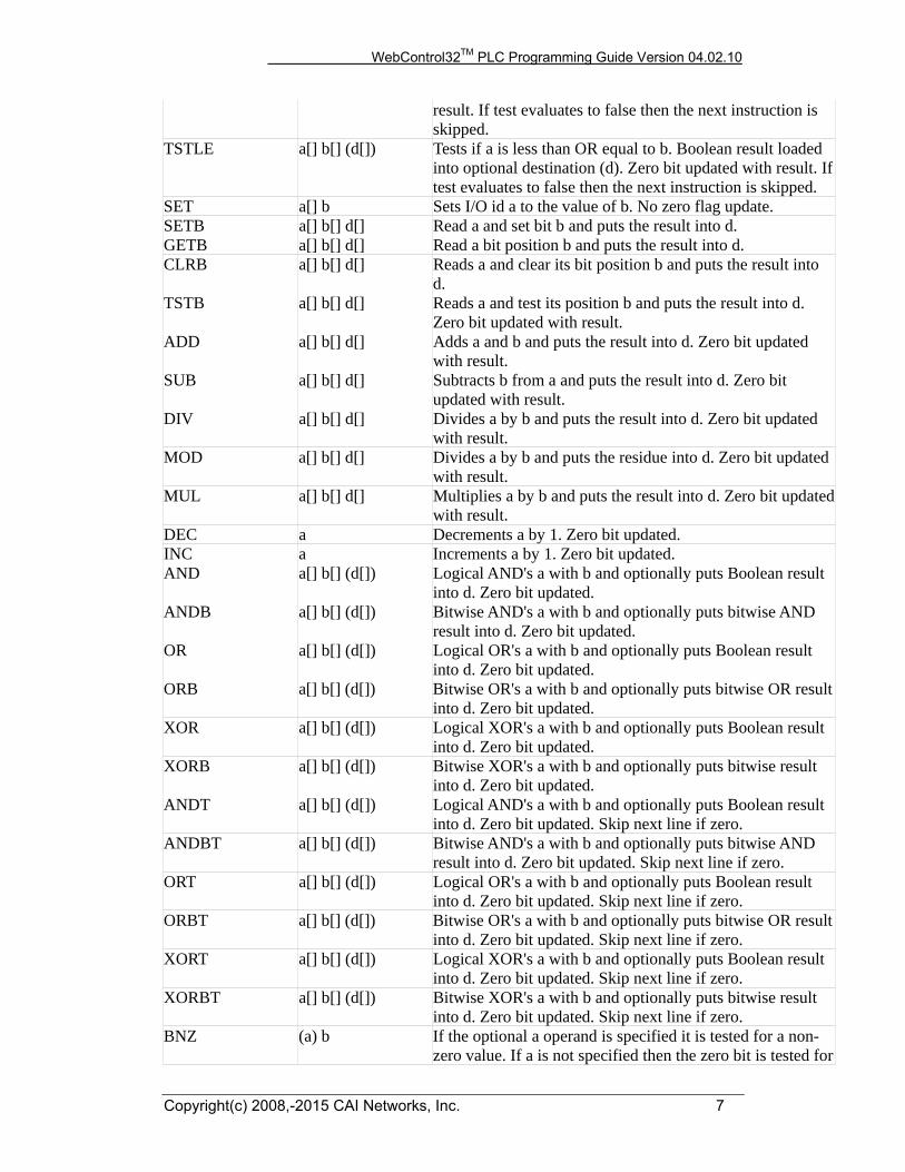
Opcode Operands Description START Start of main program PROTECTED Must be 2nd Opcode in PLC, will not display PLC code. TSTEQ a[] b[] (d[]) Tests if a is equal to b. Boolean result loaded into optional
destination (d). Zero bit updated with result. If test evaluates to false then the next instruction is skipped.
TSTNE a[] b[] (d[]) Tests if a is NOT equal to b. Boolean result loaded into optional destination (d). Zero bit updated with result. If test evaluates to false then the next instruction is skipped.
TSTGT a[] b[] (d[]) Test if a is greater than b. Boolean result loaded into optional destination (d). Zero bit updated with result. If test evaluates to false then the next instruction is skipped.
TSTLT a[] b[] (d[]) Tests if a is less than b. Boolean result loaded into optional destination (d). Zero bit updated with result. If test evaluates to false then the next instruction is skipped.
TSTGE a[] b[] (d[]) Tests if a is greater than OR equal to b. Boolean result loaded into optional destination (d). Zero bit updated with
WebControl32TM PLC Programming Guide Version 04.02.10
Copyright(c) 2008,-2015 CAI Networks, Inc. 7
result. If test evaluates to false then the next instruction is skipped.
TSTLE a[] b[] (d[]) Tests if a is less than OR equal to b. Boolean result loaded into optional destination (d). Zero bit updated with result. If test evaluates to false then the next instruction is skipped.
SET a[] b Sets I/O id a to the value of b. No zero flag update. SETB a[] b[] d[] Read a and set bit b and puts the result into d. GETB a[] b[] d[] Read a bit position b and puts the result into d. CLRB a[] b[] d[] Reads a and clear its bit position b and puts the result into
d. TSTB a[] b[] d[] Reads a and test its position b and puts the result into d.
Zero bit updated with result. ADD a[] b[] d[] Adds a and b and puts the result into d. Zero bit updated
with result. SUB a[] b[] d[] Subtracts b from a and puts the result into d. Zero bit
updated with result. DIV a[] b[] d[] Divides a by b and puts the result into d. Zero bit updated
with result. MOD a[] b[] d[] Divides a by b and puts the residue into d. Zero bit updated
with result. MUL a[] b[] d[] Multiplies a by b and puts the result into d. Zero bit updated
with result. DEC a Decrements a by 1. Zero bit updated. INC a Increments a by 1. Zero bit updated. AND a[] b[] (d[]) Logical AND's a with b and optionally puts Boolean result
into d. Zero bit updated. ANDB a[] b[] (d[]) Bitwise AND's a with b and optionally puts bitwise AND
result into d. Zero bit updated. OR a[] b[] (d[]) Logical OR's a with b and optionally puts Boolean result
into d. Zero bit updated. ORB a[] b[] (d[]) Bitwise OR's a with b and optionally puts bitwise OR result
into d. Zero bit updated. XOR a[] b[] (d[]) Logical XOR's a with b and optionally puts Boolean result
into d. Zero bit updated. XORB a[] b[] (d[]) Bitwise XOR's a with b and optionally puts bitwise result
into d. Zero bit updated. ANDT a[] b[] (d[]) Logical AND's a with b and optionally puts Boolean result
into d. Zero bit updated. Skip next line if zero. ANDBT a[] b[] (d[]) Bitwise AND's a with b and optionally puts bitwise AND
result into d. Zero bit updated. Skip next line if zero. ORT a[] b[] (d[]) Logical OR's a with b and optionally puts Boolean result
into d. Zero bit updated. Skip next line if zero. ORBT a[] b[] (d[]) Bitwise OR's a with b and optionally puts bitwise OR result
into d. Zero bit updated. Skip next line if zero. XORT a[] b[] (d[]) Logical XOR's a with b and optionally puts Boolean result
into d. Zero bit updated. Skip next line if zero. XORBT a[] b[] (d[]) Bitwise XOR's a with b and optionally puts bitwise result
into d. Zero bit updated. Skip next line if zero. BNZ (a) b If the optional a operand is specified it is tested for a non-
zero value. If a is not specified then the zero bit is tested for

WebControl32TM PLC Programming Guide Version 04.02.10
Copyright(c) 2008,-2015 CAI Networks, Inc. 8
non-zero. If true then program jumps to label specified in operand b.
BZ (a) b Same as BNZ but tests for zero value. CNZ (a) b Same as the branch instruction but calls a subroutine
instead of branching. See section on program address stack.CZ (a) b Same as above but tests for zero result. CALLSUB a Calls subroutine with label a. See section on program
address stack. GOTO a Branches to program address specified by label a. DELAY a Delay instruction, delay specified in 1/1000 seconds. This
delay is blocking delay, so that next PLC instruction will not execute until delay is over.
NOP A no operation instruction. RET A return from subroutine instruction. EMAIL a Sends email, a = message ID to send EM1 - EM8. X10 a b c a: house code 0-15, b: device code 0-15, c: ON, OFF,
BRIGHT, DIM WEBSET a b a: URL1-8, b: number or VAR, RAM or any other readableSIND a b a: degree, b: VAR or RAM to store the result COSD a b a: degree, b: VAR or RAM to store the result TAND a b a: degree, b: VAR or RAM to store the result ROTL a b c a: source register, b: number of bits; c: result register
rotate to the left, overflow bits will be feed into right ROTR a b c a: source register, b: number of bits; c: result register
rotate to the right, overflow bits will be feed to the left SETLED 0|1|2 0 to turn off green LED, 1 to turn on green LED, 2 default
blinking. IPTS a b reading TTL input last state change time tick counts. 2nd
paramter b is which TTL inut, first parameter a has the value.
IPEDGE undefined not implemented yet I2CREAD a b c a: send ack, b: send stop, c: byte to read I2CWRITE a b c a: send start, b: send stop, c: byte to write SPIBYTE a b c a: mode, b: send byte, c: byte read from bus PING a b b a: accesslist#, b: timeout 0.5ms, c: return value -1= failed,
others 0.01ms response time from host SAVE a b a is a string variable name for the USB key variable name,
b is data type LOAD a b a is a string variable name for the USB key variable name,
b is data type KEYUP return true or false KEYDOWN return true or false KEYLEFT return true or false KEYRIGHT return true or false KEYENTER return true or false KEYEXIT return true or false PRINT1 a one or more double quoted string PRINT2 a one or more double quoted string END End of main program. This instruction will set the program
counter back to zero and the program will start executing
WebControl32TM PLC Programming Guide Version 04.02.10
Copyright(c) 2008,-2015 CAI Networks, Inc. 9
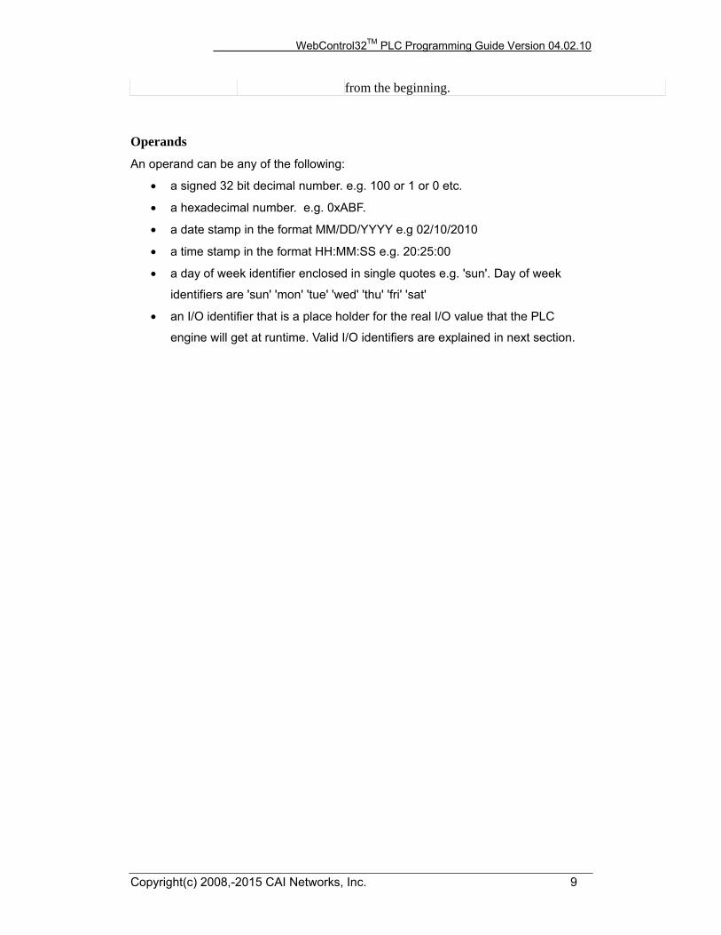
from the beginning.
Operands An operand can be any of the following:
• a signed 32 bit decimal number. e.g. 100 or 1 or 0 etc.
• a hexadecimal number. e.g. 0xABF.
• a date stamp in the format MM/DD/YYYY e.g 02/10/2010
• a time stamp in the format HH:MM:SS e.g. 20:25:00
• a day of week identifier enclosed in single quotes e.g. 'sun'. Day of week
identifiers are 'sun' 'mon' 'tue' 'wed' 'thu' 'fri' 'sat'
• an I/O identifier that is a place holder for the real I/O value that the PLC
engine will get at runtime. Valid I/O identifiers are explained in next section.

WebControl32TM PLC Programming Guide Version 04.02.10
Copyright(c) 2008,-2015 CAI Networks, Inc. 10
2.3 WebControlTM PLC I/O Identifiers The following are the valid I/O identifiers
OP1 TTL Outputs 1...16 Valid range 0 - 1
OP2
OP3
OP4
OP5
OP6
OP7
OP8
OP9
OP10
OP11
OP12
OP13
OP14
OP15
OP16
IP1 TTL Inputs 1...8 Valid range 0 - 1
IP2 When non-blocking delay added to these input,
IP3 its value will return TRUE, if input from 0->1
IP4 longer than the delay value. For example,
IP5 IP1[1000] will return FALSE, if TTL input 1 from 0
IP6 to 1 last state change shorter than 1000ms.
IP7 IP1[1000] return TRUE only when input 1 from 0 to 1
IP8 and stay at logic 1 for longer than 1000ms.
IP9
IP10
IP11
IP12
IP13
IP14
IP15
IP16
IPINV1 TTL Invert Inputs 1...8 Valid range 0 - 1
IPINV2 This is exactly same TTL input as IP1,..IP8
IPINV3 except is inverted for filter short pulse purpose
IPINV4 its usage is like: IPINV1[1000] to filter 1->0
IPINV5 pulse shorter than 1000ms. If 1->0 pulse is shorter than
IPINV6 1000ms, it will return false. Only when input state
IPINV7 changed from 1 to 0 and stay that level for longer than
IPINV8 1000ms, the value will be TRUE.
IPINV9
IPINV10
IPINV11
IPINV12
IPINV13
IPINV14
WebControl32TM PLC Programming Guide Version 04.02.10
Copyright(c) 2008,-2015 CAI Networks, Inc. 11
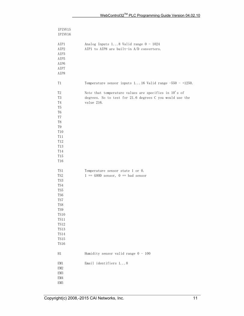
IPINV15
IPINV16
AIP1 Analog Inputs 1...8 Valid range 0 - 1024
AIP2 AIP1 to AIP8 are built-in A/D converters.
AIP3
AIP5
AIP6
AIP7
AIP8
T1 Temperature sensor inputs 1...16 Valid range -550 - +1250.
T2 Note that temperature values are specifies in 10's of
T3 degrees. So to test for 21.6 degrees C you would use the
T4 value 216.
T5
T6
T7
T8
T9
T10
T11
T12
T13
T14
T15
T16
TS1 Temperature sensor state 1 or 0.
TS2 1 == GOOD sensor, 0 == bad sensor
TS3
TS4
TS5
TS6
TS7
TS8
TS9
TS10
TS11
TS12
TS13
TS14
TS15
TS16
H1 Humidity sensor valid range 0 - 100
EM1 Email identifiers 1...8
EM2
EM3
EM4
EM5
WebControl32TM PLC Programming Guide Version 04.02.10
Copyright(c) 2008,-2015 CAI Networks, Inc. 12
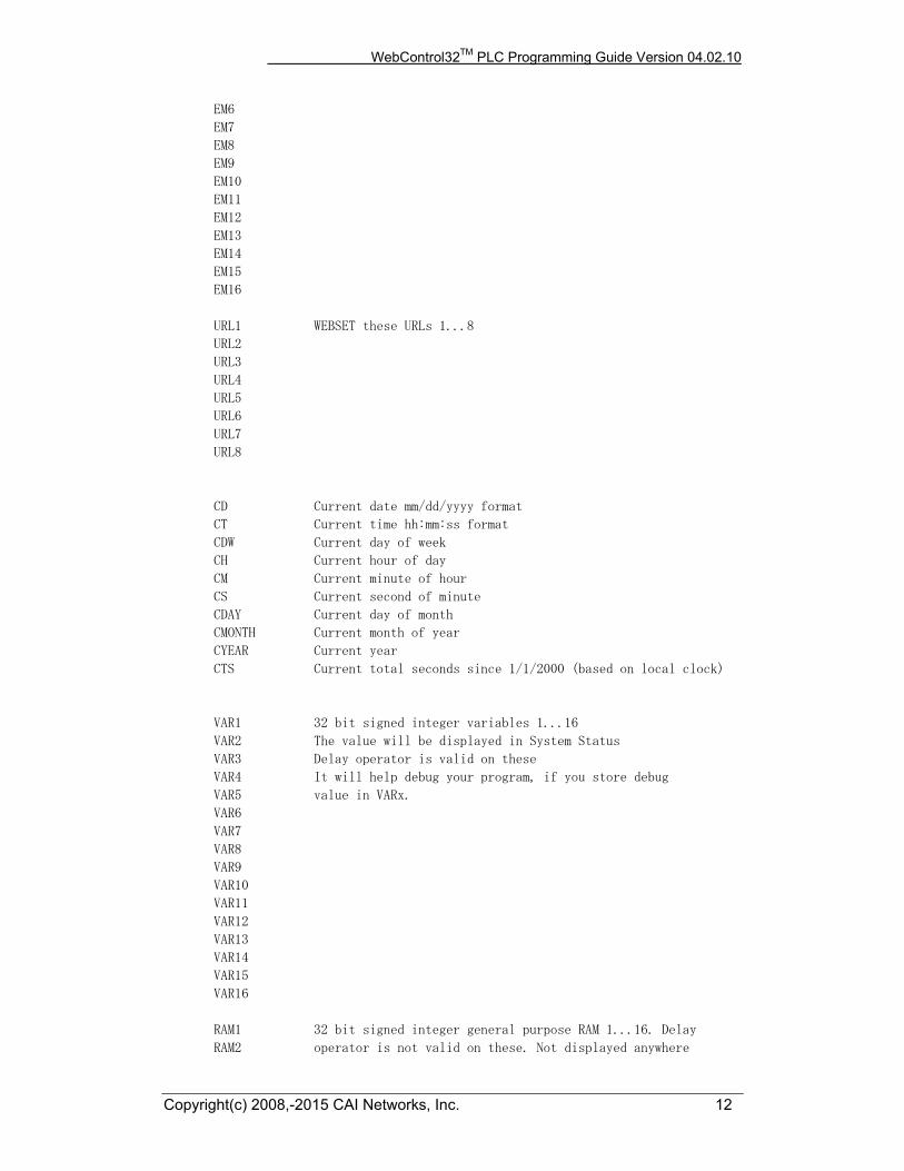
EM6
EM7
EM8
EM9
EM10
EM11
EM12
EM13
EM14
EM15
EM16
URL1 WEBSET these URLs 1...8
URL2
URL3
URL4
URL5
URL6
URL7
URL8
CD Current date mm/dd/yyyy format
CT Current time hh:mm:ss format
CDW Current day of week
CH Current hour of day
CM Current minute of hour
CS Current second of minute
CDAY Current day of month
CMONTH Current month of year
CYEAR Current year
CTS Current total seconds since 1/1/2000 (based on local clock)
VAR1 32 bit signed integer variables 1...16
VAR2 The value will be displayed in System Status
VAR3 Delay operator is valid on these
VAR4 It will help debug your program, if you store debug
VAR5 value in VARx.
VAR6
VAR7
VAR8
VAR9
VAR10
VAR11
VAR12
VAR13
VAR14
VAR15
VAR16
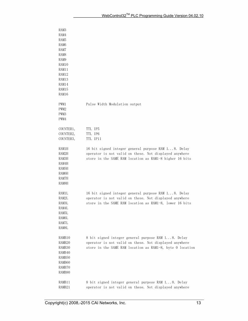
RAM1 32 bit signed integer general purpose RAM 1...16. Delay
RAM2 operator is not valid on these. Not displayed anywhere
WebControl32TM PLC Programming Guide Version 04.02.10
Copyright(c) 2008,-2015 CAI Networks, Inc. 13
RAM3
RAM4
RAM5
RAM6
RAM7
RAM8
RAM9
RAM10
RAM11
RAM12
RAM13
RAM14
RAM15
RAM16
PWM1 Pulse Width Modulation output
PWM2
PWM3
PWM4
COUNTER1, TTL IP5
COUNTER2, TTL IP6
COUNTER3, TTL IP11
RAM1H 16 bit signed integer general purpose RAM 1...8. Delay
RAM2H operator is not valid on these. Not displayed anywhere
RAM3H store in the SAME RAM location as RAM1-8 higher 16 bits
RAM4H
RAM5H
RAM6H
RAM7H
RAM8H
RAM1L 16 bit signed integer general purpose RAM 1...8. Delay
RAM2L operator is not valid on these. Not displayed anywhere
RAM3L store in the SAME RAM location as RAM1-8, lower 16 bits
RAM4L
RAM5L
RAM6L
RAM7L
RAM8L
RAMB10 8 bit signed integer general purpose RAM 1...8. Delay
RAMB20 operator is not valid on these. Not displayed anywhere
RAMB30 store in the SAME RAM location as RAM1-8, byte 0 location
RAMB40
RAMB50
RAMB60
RAMB70
RAMB80
RAMB11 8 bit signed integer general purpose RAM 1...8. Delay
RAMB21 operator is not valid on these. Not displayed anywhere
WebControl32TM PLC Programming Guide Version 04.02.10
Copyright(c) 2008,-2015 CAI Networks, Inc. 14
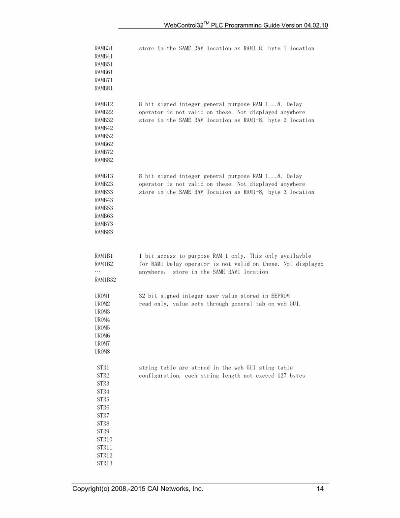
RAMB31 store in the SAME RAM location as RAM1-8, byte 1 location
RAMB41
RAMB51
RAMB61
RAMB71
RAMB81
RAMB12 8 bit signed integer general purpose RAM 1...8. Delay
RAMB22 operator is not valid on these. Not displayed anywhere
RAMB32 store in the SAME RAM location as RAM1-8, byte 2 location
RAMB42
RAMB52
RAMB62
RAMB72
RAMB82
RAMB13 8 bit signed integer general purpose RAM 1...8. Delay
RAMB23 operator is not valid on these. Not displayed anywhere
RAMB33 store in the SAME RAM location as RAM1-8, byte 3 location
RAMB43
RAMB53
RAMB63
RAMB73
RAMB83
RAM1B1 1 bit access to purpose RAM 1 only. This only availavble
RAM1B2 for RAM1 Delay operator is not valid on these. Not displayed
… anywhere, store in the SAME RAM1 location
RAM1B32
UROM1 32 bit signed integer user value stored in EEPROM
UROM2 read only, value sets through general tab on web GUI.
UROM3
UROM4
UROM5
UROM6
UROM7
UROM8
STR1 string table are stored in the web GUI sting table
STR2 configuration, each string length not exceed 127 bytes
STR3
STR4
STR5
STR6
STR7
STR8
STR9
STR10
STR11
STR12
STR13

WebControl32TM PLC Programming Guide Version 04.02.10
Copyright(c) 2008,-2015 CAI Networks, Inc. 15
STR14
STR15
STR16
STR17
STR18
STR19
STR20
STR21
STR22
STR23
STR24
STR25
STR26
STR27
STR28
STR29
STR30
STR31
STR32
KEYUP,
KEYDOWN,
KEYLEFT,
KEYRIGHT,
KEYENTER,
KEYEXIT,
COUNTER 32 bit counter can be read, compare, or set
//FCOUNTER read only, frequency per second up to 2MHz.
WSRPLY read and write, automatically set by web server during WEBSET
call when server specified a value like "SET_WC=12345678".
LED read and write, When read 0 means LED is off, 1 means LED is
on, 2 means LED is heart beat. When write, valie is 0,1,or 2.
ALLINS read only, All 8 TTL as a byte. Only in 3.02.17a firmware
ALLOUTS read write, All 8 TTL output as a byte, only in 3.02.17a
firmware.
2.4 WebControl PLC Examples
For best understanding how PLC logic working, you can try to copy and paste the examples below into your WebControl PLC program screen to check them out. Please note PLC logic will execute from START to END. Then it will continue from START to END, forever repeating. If you last line of PLC code could skip next instruction, like those TST instruction, it might skip your first line when condition met. Please do pay attention to it. If you use CALLSUB to run subroutine, after finishing the subroutine, the logic will return back to where CALLSUB called and continue.
WebControl32TM PLC Programming Guide Version 04.02.10
Copyright(c) 2008,-2015 CAI Networks, Inc. 16
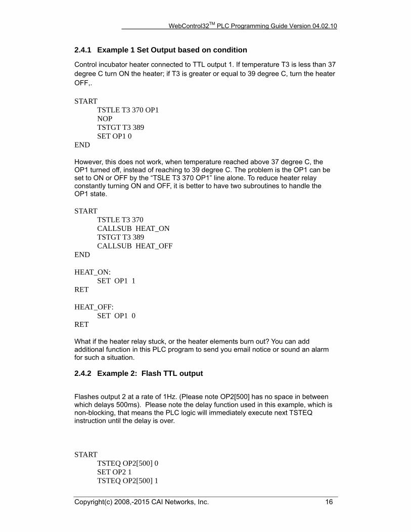
2.4.1 Example 1 Set Output based on condition
Control incubator heater connected to TTL output 1. If temperature T3 is less than 37 degree C turn ON the heater; if T3 is greater or equal to 39 degree C, turn the heater OFF,. START TSTLE T3 370 OP1 NOP TSTGT T3 389 SET OP1 0 END However, this does not work, when temperature reached above 37 degree C, the OP1 turned off, instead of reaching to 39 degree C. The problem is the OP1 can be set to ON or OFF by the “TSLE T3 370 OP1” line alone. To reduce heater relay constantly turning ON and OFF, it is better to have two subroutines to handle the OP1 state. START TSTLE T3 370 CALLSUB HEAT_ON TSTGT T3 389 CALLSUB HEAT_OFF END HEAT_ON: SET OP1 1 RET HEAT_OFF: SET OP1 0 RET What if the heater relay stuck, or the heater elements burn out? You can add additional function in this PLC program to send you email notice or sound an alarm for such a situation.
2.4.2 Example 2: Flash TTL output
Flashes output 2 at a rate of 1Hz. (Please note OP2[500] has no space in between which delays 500ms). Please note the delay function used in this example, which is non-blocking, that means the PLC logic will immediately execute next TSTEQ instruction until the delay is over. START
TSTEQ OP2[500] 0 SET OP2 1 TSTEQ OP2[500] 1
WebControl32TM PLC Programming Guide Version 04.02.10
Copyright(c) 2008,-2015 CAI Networks, Inc. 17
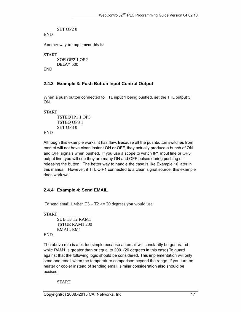
SET OP2 0 END Another way to implement this is: START
XOR OP2 1 OP2 DELAY 500 END
2.4.3 Example 3: Push Button Input Control Output
When a push button connected to TTL input 1 being pushed, set the TTL output 3 ON. START TSTEQ IP1 1 OP3 TSTEQ OP3 1 SET OP3 0 END Although this example works, it has flaw. Because all the pushbutton switches from market will not have clean instant ON or OFF, they actually produce a bunch of ON and OFF signals when pushed. If you use a scope to watch IP1 input line or OP3 output line, you will see they are many ON and OFF pulses during pushing or releasing the button. The better way to handle the case is like Example 10 later in this manual. However, if TTL OIP1 connected to a clean signal source, this example does work well.
2.4.4 Example 4: Send EMAIL
To send email 1 when T3 – T2 >= 20 degrees you would use: START SUB T3 T2 RAM1 TSTGE RAM1 200
EMAIL EM1 END The above rule is a bit too simple because an email will constantly be generated while RAM1 is greater than or equal to 200. (20 degrees in this case) To guard against that the following logic should be considered. This implementation will only send one email when the temperature comparison beyond the range. If you turn on heater or cooler instead of sending email, similar consideration also should be excised: START
WebControl32TM PLC Programming Guide Version 04.02.10
Copyright(c) 2008,-2015 CAI Networks, Inc. 18
SET RAM2 0 LOOP: SUB T3 T2 RAM1 TSTGE RAM1 200 RAM1 GOTO SEND SET RAM2 0 GOTO LOOP END SEND: BNZ RAM2 LOOP SET RAM2 1 EMAIL EM1 GOTO LOOP Please note in SEND portion of the code, RAM2 is being checked, if it is already 1, it will skip sending email. Only when RAM2 == 0, an email will be send. Only when RAM1 < 200, the LOOP will skip SEND logic and reset RAM2 to 0.
2.4.5 Example 5, Parallel I/O
This simple program performs 4 separate I/O checks and sets OP1 to OP4 states. In this example, we use subroutine feature of the PLC logic. Although in this case, GOTO can do same thing as CALLSUB, CALLSUB can help program more readable. In certain logic, you have to use CALLSUB instead of GOTO, depending on the logic flow. We will explain more when we run into those examples. The logic in this example follows:
OP1 is set if T3 > 50
OP1 is cleared if T3 < 50
OP2 is set if IP1 == 1 for more than 300ms
OP2 is cleared if IP1 == 0
OP3 is set if AIP1 + AIP2 > 1024
OP3 is cleared if IP4 == 1
OP4 is set if OP1 == 1
OP4 is cleared if OP1 == 0
The PLC code written for the above scenarios would be as follows:
START CALLSUB checkOP1 CALLSUB checkOP2
WebControl32TM PLC Programming Guide Version 04.02.10
Copyright(c) 2008,-2015 CAI Networks, Inc. 19
CALLSUB checkOP3 CALLSUB checkOP4 END checkOP1: TSTGT T3 500 OP1 RET checkOP2: TSTEQ IP1[300] 1 OP2 RET checkOP3: ADD AIP1 AIP2 RAM1 TSTGT RAM1 1024 BNZ l1 TSTEQ IP4 1 BNZ l2 RET l1:
SET O3 1 RET l2:
SET O3 0 RET checkOP4: TSTEQ OP1 1 OP4 RET Please note in this example, we assume the TTL input, analog input and temperature reading are all perfect, no bouncing up and down. In reality, you have to add consideration to it.
2.4.6 Example 6, Sequential I/O
The following simple program shows how to set-up sequential I/O. OP1 is set when IP1 rises from 0 to 1 OP4 is cleared when IP1 rises from 0 to 1 OP1 is cleared when O4 == 1 OP2 is set when T3 > 25 AND OP1 == 1 OP2 is cleared when OP1 == 0 EMAIL1 is sent when OP2 is set O4 is set when OP2 == 1 for more than 1 second The assembly language written for the above scenario would be as follows:

WebControl32TM PLC Programming Guide Version 04.02.10
Copyright(c) 2008,-2015 CAI Networks, Inc. 20
START BNZ IP1 start l1:
TSTEQ IP1 1 BZ l1 SET OP1 1 SET OP4 0 l2:
TSTGT T3 250 RAM1 AND OP1 RAM1 BZ l2 SET OP2 1 EMAIL EM1 l3:
TSTEQ OP2[1000] 1 BZ l3 SET OP4 1 SET OP1 0 END Please note in this example, we assume the TTL input, analog input and temperature reading are all perfect, no bouncing up and down. In reality, you have to add consideration to it.
2.4.7 Example 7, Traffic Lights
This example will let pedestrian to push a button to change the light on a busy street, so that he can cross the street safely. IP1 hooks up to the pedestrian crossing button. If someone pushed cross button, the street will have amber light on for 10 seconds, then red light to stop all the cars, allowing pedestrian to cross street in next 30 seconds. At the end of 30 seconds, it will flash the amber and red light for 5 seconds. VAR1 in the main program will let the crossing light turn on every 100 seconds, does not matter anybody push the crossing button or not. OP1 Red + Pedestrian crossing light OP2 Amber OP3 Green IP1 Pedestrian Push Button
START CALLSUB LIGHTS_GO loop: SET VAR1[10000] 1 loop1: TSTEQ IP1 1
WebControl32TM PLC Programming Guide Version 04.02.10
Copyright(c) 2008,-2015 CAI Networks, Inc. 21
BNZ sr BZ VAR1 sr GOTO loop1 sr: CALLSUB STOP GOTO loop END LIGHTS_ST: SET OP1 1 SET OP2 0 SET OP3 0 RET LIGHTS_GO: SET OP1 0 SET OP2 0 SET OP3 1 RET LIGHTS_AM: SET OP1 0 SET OP2 1 SET OP3 0 RET STOP: CALLSUB LIGHTS_AM DELAY 5000 CALLSUB LIGHTS_ST DELAY 60000 CALLSUB LIGHTS_AM SET RAM2 5 flash: XOR OP2 1 OP2 DELAY 500 DEC RAM2 BNZ flash CALLSUB LIGHTS_GO RET
WebControl32TM PLC Programming Guide Version 04.02.10
Copyright(c) 2008,-2015 CAI Networks, Inc. 22
2.4.8 Example 8, Time based Control
WARNING: For time critical application, please make sure to check CYEAR correct
before taking action based on system clock. When WebControlTM boot up, it will uses
ROM hard coded time in 2011. If PLC reporting year 2011, the NTP or real time clock
has not sync the local clock yet.
This example will have five subroutines. WebControlTM PLC will continuously loop
through them. The “HOURLY” routing will compare analog input 1 and analog input 2,
if A1 - A2 > 10, send an email notice 1. You can use similar logic to adjust your solar
panel orientation each hour, etc. The “PERIOD” subroutine will turn on night light
hooked up to OP1 after 18:00 hours and turn it off at 5AM. The “DAILY” subroutine
will start the water sprinkler at 6:30AM for four zones. The “MONTHLY” routing will
check the “salt low” sensor AIP3 on the water softener and send email notice 2. The
“YEARLY” routing will ring the New Year’s bell connected to OP6 on each and every
New Year’s Day for the whole day!
START CALLSUB HOURLY CALLSUB PERIOD CALLSUB DAILY CALLSUB MONTHLY CALLSUB YEARLY END HOURLY: TSTNE RAM1 CH GOTO T1 RET T1: SET RAM1 CH SUB AIP1 AIP2 RAM2 TSTGT RAM2 10 EMAIL EM1 RET PERIOD: TSTGE CH 18 RAM2 NOP TSTLE CH 5 RAM3 NOP OR RAM2 RAM3 OP1 RET

WebControl32TM PLC Programming Guide Version 04.02.10
Copyright(c) 2008,-2015 CAI Networks, Inc. 23
DAILY: TSTEQ CH 7 SET RAM5 0 TSTEQ CH 6 BZ NOTYET TSTGT CM 30 CALLSUB WATERING NOTYET: RET MONTHLY: TSTNE RAM4 CMONTH GOTO T2 RET T2: TSTLE CH 8 GOTO 2EARLY SET RAM4 CMONTH TSTLT AIP3 20 EMAIL EM2 2EARLY: RET YEARLY: TSTEQ CMONTH 1 RAM2 NOP TSTEQ CDAY 1 RAM3 NOP AND RAM2 RAM3 OP6 RET WATERING: BNZ RAM5 W_DONE ZONE1: SET OP2 1 TSTLE CM 35 GOTO ZONE1 SET OP2 0 ZONE2: SET OP3 1 TSTLE CM 40 GOTO ZONE2 SET OP3 0 ZONE3: SET OP4 1 TSTLE CM 45 GOTO ZONE3 SET OP4 0 ZONE4:
WebControl32TM PLC Programming Guide Version 04.02.10
Copyright(c) 2008,-2015 CAI Networks, Inc. 24
SET OP5 1 TSTLE CM 50 GOTO ZONE4 SET OP5 0 SET RAM5 1 W_DONE: RET Please note in DAILY subroutine, we call another subroutine “watering”. In this place, we have to use subroutine, since we only want to call this routine after 6:30AM. If current minute is not 30, we will skip. Watering will be done before 7AM, so that we clear the flag RAM5 at 7AM. Also, please notice RAM1, RAM4 and RAM5 are holding static value and RAM2 and RAM3 are temporary storage being used by more than one subroutine. You can decide which RAM is for temporary data, which is for static value. In the PERIOD subroutine, we constantly compare the time and set the OP1 ON or OFF. That is okay for solid state relay or other control relay, since the logic level did not change all the time. However, if you are sending a X10 command to turn on and off different lights, you want to make sure the X10 command only issued once, not repeatedly. You may create another subroutine in which set flag only calls X10 1 15 ON only once to turn ON light at house code 2, unit code 16 (please note WebControl’s X10 house code range 0-F, and device code range also 0-F.) In the MONTHLY routine, we first check the current hour being 8AM then we check the water softener’s salt level. In this way you will not be waked up by email in the midnight. When program WebControl PLC for time based logic, please make sure the time being used in different part of the program having no conflict between all the subroutines. If you want two things to happen at the same time, you should consider combine them into same routine to handle.
2.4.9 Example 9, Battery Charger
This is a PLC program to charge 3 serially connected NiMH batteries. First, it tries to discharge the batteries individually. If any battery discharged to 1V, it will stop the discharge and start charging. When each cell is being charged to 1.25V, it will stop charging. We assume the A1, A2, and A3 being calibrated to 1V=100. The measurement on the battery 2 is the total voltage of battery 1 and battery 2. And the measurement on battery 3 is the total voltage of all three batteries. This example will individually discharge and charge each battery. start
set op1 1 set op2 1 set op3 1 set RAM1 0 set RAM2 0 set RAM3 0
loop:
WebControl32TM PLC Programming Guide Version 04.02.10
Copyright(c) 2008,-2015 CAI Networks, Inc. 25
cnz op1 check_b1 cnz op2 check_b2 cnz op3 check_b3
goto loop end check_b1:
BNZ RAM1 c1 tstle AIP1 100 RAM1 bz e1
c1: tstgt AIP1 125 bnz e1 set op1 0 set op4 1
e1: ret check_b2:
BNZ RAM2 c2 sub AIP2 AIP1 RAM4 tstle RAM4 100 RAM2 bz e2
c2: sub AIP2 AIP1 RAM4 tstgt RAM4 125 bnz e2 set OP2 0 set OP5 1
e2: ret check_b3:
BNZ RAM3 c3 sub AIP3 AIP2 RAM4 sub RAM4 AIP1 RAM4 tstle RAM4 100 RAM3 bz e3
c3: sub AIP3 AIP2 RAM4 sub RAM4 AIP1 RAM4 tstgt RAM4 125 bnz e3 set OP3 0 set OP6 1
e3: ret
2.4.10 Example 10, RFID reader and browser Control
For office door using RFID reader, as well as allowing operator remote browser control, the following program provided the example. RFID reader’s NC (normally connect) output connects to IP1 on WebControl digital input. A 2.2K pull-up resistor
WebControl32TM PLC Programming Guide Version 04.02.10
Copyright(c) 2008,-2015 CAI Networks, Inc. 26
also connected between IP1 and 5V. In this way, each time a valid RFID tag sensed, a TTL “1” feeds to WebControl IP1. Remote operator can also open the door by using browser set OUTPUT TTL1 to on. OP1 connects to the door open switch. TESTEQ logic will make sure the OP1 is an 1 second momentary output. “LIGHTS” subroutine is for light control outside the office door; the light is on at 7PM and off at 5AM.
START CALLSUB LIGHTS TSTEQ RAM1 0 CALLSUB SET_OP1 CALLSUB CHK4LOW TSTEQ OP1[1000] 1 SET OP1 0 END CHK4LOW: TSTEQ IP1 0 SET RAM1 0 RET SET_OP1: TSTEQ IP1 1 RAM1 SET OP1 1 RET LIGHTS: TSTGE CH 19 RAM2 NOP TSTLE CH 5 RAM3 NOP OR RAM2 RAM3 OP3 RET In this logic, SET_OP1 must be subroutine, if “TSTEQ RAM1 0” it will call the subroutine SET_OP1, but if RAM1 != 0, then it will skip that call. In this way, we can guarantee OP1 only being turn on once. In the subroutine SET_OP1, it checks if RFID reader did detected valid RDID card present. If so, it will set the flag RAM1 to true, so that not being set over and over again. For gate opening device, this will make sure the gate will not left open all the time.
2.4.11 Example 11, Bitwise Operation
There are ANDB, ORB, and XORB operator operate on the VAR or RAM on the bit basis. This will allow each RAM or VAR to store up to 31 binary states. When VAR1 stores value 12345, and RAM1 stores value 256, after execute ANDB VAR1 RAM1 VAR1 VAR1 stores the value 0

WebControl32TM PLC Programming Guide Version 04.02.10
Copyright(c) 2008,-2015 CAI Networks, Inc. 27
After execute: ORB VAR1 RAM1 VAR1 VAR1 stores the value 123712 XORB VAR1 RAM1 VAR1 First execution will be 123712, if execute next time, VAR1 will be back to 12345. In another word, XORB can toggle the bit.
2.4.12 Example 12, Angle Calculation
From 3.02.16c firmware, angle calculation is supported. In PLC program, users can: SIND 91 VAR1 Or COSD 185 VAR2 Or TAND 630 VAR3 The result for SIND and COSD is x1000, because we can only have integer on this processor. The result for TAND is x100.
2.4.13 Example 13, Non-Blocking Delay
Non-blocking delay is expressed in PLC code as [] next to the operators. The number inside [] is micro-seconds. The [] operation can be on both operators during TST operations. Each input and output and VAR associated with a non-blocking delay timer value. That value is set when I/O state is changed or VAR value being modified. If later PLC instruction using non-blocking delay, that timer value will be referenced. If current time is less than stored timer time plus the delay period, the specified operation will not be performed. Reading value with non-blocking delay will return false if timer value is not meet For example, TSTGT VAR1[1500] IP1[300] RAM2 If any of those delay not reached, its result will be FALSE. For SET VAR1[15000] IP1 VAR1 will not be set to IP1 value, unless 15000 milliseconds (15seconds) passed.
2.4.14 Example 14, WEBSET to get server reply
From 3.02.16 version firmware, WebControl allows PLC call WEBSET to do HTTP GET call to HTTP servers inside another WebControl or other devices, or Apache or IIS servers. The web server CGI code can process that information. From 3.02.17 version firmware, the web server can also send back to the WebControl a specially formatted string. When WebControl received that string, it will set an internal variable for user PLC code to reference. Following is an example CGI code from apache server that will set the WebControl WSRPLY in the WebControl. PLC program can base on that reply to turn on or off an I/O bit or take any other action. Because PLC code does not execute WEBSET call immediately, rather WEBSET is on a scheduler called from queue, user can not expect to get server reply immediately after WEBSET call. The good practice would to check if the WSRPLY value is zero, if that is zero, the server reply has not fetched back yet. Server must
WebControl32TM PLC Programming Guide Version 04.02.10
Copyright(c) 2008,-2015 CAI Networks, Inc. 28
return a non-zero value back. If WSRPLY is non-zero, user PLC must read it into another variable and set it to zero, so that it can be used for next WEBSET call. In this sense, if PLC logic wants to get multiple values from server reply, it must issue one call at a time to avoid different WEBSET call return value clashing.
2.4.15 Example 15, Server CGI Handles WEBSET
The code below is for demonstration only, it is written in C on apache server. We do not provide support for writing server CGI code. Please note to get the best result, server CGI code should write back the string as early in the reply as possible. In HTTP server reply processing, server mostly after sending reply will close connection. If the “SET_WC=2147483647” string sending out too late, it could get lost because the connection is closed already. Please test and make sure your server is response fast enough for the WEBSET call.
#include <stdio.h>
#include <stdlib.h>
#include <string.h>
int main(void)
{
char *data, *remote_mac, *remote_host;
long m,n;
FILE *fp;
char buffer[18] = "\r\nnew get call\r\n";
printf("%s%c%c\n",
"Content-Type:text/plain;charset=iso-8859-1",13,10);
data = getenv("QUERY_STRING");
remote_mac = getenv("HTTP_USER_AGENT");
remote_host = getenv("REMOTE_ADDR");
fp = fopen("/tmp/webcontrol.txt", "w+");
fwrite(buffer, 1, strlen(buffer), fp);
if(data != NULL) {
fwrite(data, 1, (unsigned int) strlen(data), fp);
fwrite(buffer, 1, strlen(buffer), fp);
}
if(remote_host != NULL) {
fwrite(remote_host, 1, (unsigned int) strlen(remote_host), fp);
fwrite(buffer, 1, strlen(buffer), fp);
}
if(remote_mac != NULL) {
WebControl32TM PLC Programming Guide Version 04.02.10
Copyright(c) 2008,-2015 CAI Networks, Inc. 29
fwrite(remote_mac, 1, (unsigned int) strlen(remote_mac), fp);
fwrite(buffer, 1, strlen(buffer), fp);
} else
fwrite(buffer, 1, strlen(buffer), fp);
/***************************************************
put your logic here if MAC address not match then do what
You can simply return with an error message
****************************************************/
/****************************************************
Now, you can process the data string send in by WebControl
****************************************************/
printf("to push up to 10 bytes to WebControl SET_WC=-2147483647\n");
printf("close connection\n");
fclose(fp);
return 0;
}
2.4.16 Example 16, USB key SAVE and LOAD functions
We now have the load/save user values to the usb pen drive too. Two new PLC
instructions are available LOAD and SAVE that can be used by the user to save the
values of I/O ID’s to the flash drive. They are used like this:
LOAD “myval” RAM1
to read back saved “myval” to RAM1. Or write to USB pen drive:
SAVE “myval” IP2
Or
LOAD “myval” PWM2
to load “myval” to USB drive. The first operand must be a string literal ; this is used
as the name of the value. You will see that all of these name value pairs are stored
on disk as a xxx.dat file where xxx is the name given by the string literal operand. (file
is binary for ease of processing when loading and saving).
WebControl32TM PLC Programming Guide Version 04.02.10
Copyright(c) 2008,-2015 CAI Networks, Inc. 30
Note that these instructions will fail if a USB drive is not attached or the value does
not exist on a LOAD. In which case the next instruction is skipped i.e.
LOAD “value1” RAM2
CALLSUB dowork ; this instruction is skipped if the load fails.
GOTO start
Similarly:
SAVE “value1” RAM2
CALLSUB dowork ; this instruction is skipped if the save fails.
GOTO start
Once again note that the LOAD and SAVE instructions are very slow and will slow
down the execution of the PLC program and hog CPU bandwidth so user should use
them with care and avoid calling these too often.
2.4.17 Example 17, USB LCD Display and Push Kay functions
The following example shows how to read from the UM216 key stoke and display
information to the LCD display through PLC program.
START
PRINT1 "PRESS A KEY"
BEGIN:
TSTEQ KEYUP 1
GOTO KUP
TSTEQ KEYDOWN 1
GOTO KDOWN
TSTEQ KEYLEFT 1
GOTO KLEFT
TSTEQ KEYRIGHT 1
GOTO KRIGHT
TSTEQ KEYENTER 1
GOTO KENTER
TSTEQ KEYEXIT 1
GOTO KEXIT
PRINT2 ""
GOTO BEGIN

WebControl32TM PLC Programming Guide Version 04.02.10
Copyright(c) 2008,-2015 CAI Networks, Inc. 31
KUP:
PRINT2 "UP =" "PRESSED"
GOTO BEGIN
KDOWN:
PRINT2 "DOWN =" "PRESSED"
GOTO BEGIN
KLEFT:
PRINT2 "LEFT =" "PRESSED"
GOTO BEGIN
KRIGHT:
PRINT2 "RIGHT =" "PRESSED"
GOTO BEGIN
KENTER:
PRINT2 "ENTER =" "PRESSED"
GOTO BEGIN
KEXIT:
PRINT2 "EXIT =" "PRESSED"
GOTO BEGIN
END
2.4.18 Example 18, I2C PLC Programming ADS1115
The following example shows how to communicate to a 16 bit ADC chip on I2C bus
through PLC program. START CALLSUB ADS1115 END ADS1115: I2CWRITE 1 0 144 # I2c start, write address for chip # with addr connected to ground I2CWRITE 0 0 1 # configuration register address is 1 I2CWRITE 0 0 193 # single end AINp = A0, full scale # 6.144V, one shot conversion, # see page 18-19 I2CWRITE 0 1 131 # 128 sample/s, disable comparator, DELAY 10 # wait for conversion done, WC8 stop # write to chip I2CWRITE 1 0 144 # I2c starts, write to chip on this # I2c address I2CWRITE 0 1 0 # tell ADS1115 we address register 0, # send STOP
WebControl32TM PLC Programming Guide Version 04.02.10
Copyright(c) 2008,-2015 CAI Networks, Inc. 32
I2CWRITE 1 0 145 # I2c starts, tell chip we will read BNZ NO_DEV # if device exist? not, then do not # read <<---- change I2CREAD 0 0 RAM11 # reads MSB byte, notice ADS1115 # require ACK, which is zero in ACK # bit I2CREAD 0 1 RAM10 # reads lower byte, send stop to tell # ADS1115 no more read MUL RAM1L 1872 VAR1 # 1872 is the scale factor for 6.144 # full scale reading DIV VAR1 10000 VAR5 # divide by 10000 to set value to # 0.001V scale, store in VAR5 RET NO_DEV: I2CWRITE 1 1 144 # release I2C bus by insert STOP bit # to bus <<---- must SET VAR5 0 # ADS1115 not on I2C bus, so set VAR5 # to zero RET
Since firmware 4.02.09, WC32 firmware supports DS1307 I2C RTC in the firmware.
When writing PLC program with I2C support, user need to pay attention to make
sure if the target I2C device is not on the bus, PLC program needs to send stop bit to
release I2C bus for kernel to read and write to RTC chip on the same I2C bus.
2.4.19 Example 19, PING another host in PLC
The following example shows how to communicate to a 16 bit ADC chip on I2C bus
through PLC program.
START
PING 1 100 VAR1 END
where the first parameter 1 refers to the first Access Limit address in Network tab
the second parameter 100 is for waiting 100x 0.5ms
PING result will be set in 3rd parameter, in the above example, that is VAR1. If the return value is -1, ping failed. Otherwise, the number indicated how many 0.01mS WC32 has been waiting till ICMP reply received

WebControl32TM PLC Programming Guide Version 04.02.10
Copyright(c) 2008,-2015 CAI Networks, Inc. 33
3 WebControlTM PLC FAQ We include some users frequently asked questions here:
3.1 Login and Configuration
1-1Q: Can you tell me how to connect with Windows Explore? I cannot communicate? 1-1A: If you have DHCP server on your network, please check with your DHCP server log, WebControl is likely obtained an IP address from your DHCP server. Once your find out the IP address assigned by DHCP server, you can use browser to connect to: http://what-ever-dhcp-assigned-ip/ You will see the login screen. If you don′t have DHCP server on your network, WebControl's default IP address is 192.168.1.15. You must change your computer's IP address temporarily to 192.168.1.1, (make sure no other host using that IP address on your network), then from IE browser enter: http://192.168.1.15/ You will see the login screen. 1-2Q: I have problem to setup the clock, it does not work, even I setup my network and DNS server correctly? 1-2A: Please check with your ISP to make sure the DNS server IP address is valid. If you have Linux computer, you can use dig command to make sure that DNS server IP can resolve the ntp.org. Please note that many ISPs restrict the DNS access from outside its own IP address range. If your DNS server IP is not from your ISP, it may not work. dig ntp.org @your-dns-server-ip 1-3Q: What is the default user ID and password, can I change it? 1-3A: The default user ID and password is admin/password, all lower case. User can change both user ID and password.
3.2 Temperature Sensor Support
2-1Q: The document stated supporting DS1822/DS1820 1 Wire Temperature
Sensors, I assumed the whole DS18xx family of devices would work. I used a
DS18S20+ and get about 3.5 degrees C when powered, 10.6 when parasitic
powered. It should read 23-24 at room temperature. For power I tried pin 3 of the
temperature terminal and pin 3 of the humidity terminal and the result is the same.
2-1A: WebControl™ can simultaneously connect 8 optional
DS18B20/DS1822/DS18S20 based digital temperature sensors. In the past we
require 12bit temperature sensor. Now, we lose the requirement to 12bit and 9 bit
Maxim-IC temp sensors. We still do not support parasite part.
2-2Q: How to read temperature or sensor ROM code from command line in Linux?
WebControl32TM PLC Programming Guide Version 04.02.10
Copyright(c) 2008,-2015 CAI Networks, Inc. 34
2-2A: Use wget http://webcontrol-ip/gett1.cgi to read the temp sensor T1, and use
wget http://webcontrol-ip/gett1rc.cgi to read the sensor T1 ROM code.
2-3Q: What can cause my temperature sensor not display correctly?
2-3A: Use solid copper wire for your 1-wire bus, for example, CAT5 cable. Reduce
any unnecessary length of the wire. Do not hook up unsupported parts to the 1-wire
bus, since they may generate 1-wire signal causing trouble.
2-4Q: I run a long cable between the DS18B20 and WebControl, sensor does not
work?
2-4A: According to Maxim-IC, if using a long cable connecting between the sensor
and host controller, it may require to add a pull-up resistor 4.7k from 1-wire bus (DQ
pin on DS18B20) to the 5V supply near the far end of the 1-wire bus. Please check
out Maxim-IC AppNote148. You do not have to add external power, if you do not
experience any problem.
3.3 Turn on/off TTL output from another programming language
3-1Q: I want to turn on/off TTL output from Visual Basic, can I do it?
3-1A: You can reference how the browser does it and emulate that in your VB or
script. Please make sure to disable login in the "Network Setup" screen. For security
purpose, please specify the IP address in the access list, or your application sending
encrypted user ID/password in the same HTTP call. Depends on the IP address and
which TTL you want to control by programming language, you may refer to these two
browser URL lines:
http://192.168.1.15/api/setttloutput.cgi?output=1&state=1 to turn on,
http://192.168.1.15/api/setttloutput.cgi?output=1&state=0 to turn off.
and to manually set a VAR value from outside, varid from 1 to 8:
http://192.168.1.15/api/setvar.cgi?varid=1&value=23456789
from 3.02.17 firmware, WebControl supports manually set a UROM value from
outside, uromid from 1 to 4:
http://192.168.1.15/api/seturom.cgi?uromid=1&value=23456789
Command line browser wget can be used to do manually control. The above lines
maybe need in double quotes to work.

WebControl32TM PLC Programming Guide Version 04.02.10
Copyright(c) 2008,-2015 CAI Networks, Inc. 35
3.4 Power Supply Requirement
5-1Q: What kind of power required to run WebControl?
5-1A: WebControl 32 hw rev 4/5/6 hardware can operate from 7.5 to 12VDC power
supply. However, when using DC12V, the regulator will be VERY hot. It is
recommended to run on 9VDC1A power supply.
WebControl HW rev 7 changed using a switch IC to regulate the power, it can take
from 4.5V to 20VDC. Its max absolute DC input voltage is 26VDC, beyond that will
cause permanent damage.
Please make sure power supply has good filtering capacitors. Any noise in the
power supply could cause problem during execution of WebControl PLC logic. If a
relay board is also used with WebControl, please make sure the power supply has
enough reverse current to handle the spike during relay switching.