engineeringprojects.comengineeringprojects.com/tender/uploadfiles/1596... · web viewcontents....
TRANSCRIPT

TECHNICAL SPECIFICATIONS FOR ELECTRICAL SYSTEM
CONTENTS
SL.NO.DESCRIPTION
) SOCKETANNEXURE FOR SWITCHGEARS SUMMARY OF LT PANELS
AND BOARDS
2TECHNICAL SPECIFICATIONS
3LIST OF APPROVED MAKE OF MATERIAL
SIGNATURE OF TENDERER WITH SEAL EMPLOYER
Page 1 of 441

ANNEXURE FOR SWITCHGEARS SUMMARY OF LT PANELSNOTE : In case of any discrepancy between the yechnical specifications for electtrical system and associated SLD(Single Line Diagram) , the technical description shall be given precedence . Hence the parties are requested to quote as per Technical Specifications of BOQ. To be read in conjunction with SLD
PANEL NO 2 380 V MAIN LT PANEL
SL.NO.DESCRIPTION UNIT QUANTITY
METERING, INDICATION AND PROTECTION1 32A TP MCB WITH ISOLATOR No 1
2 20A TPN MCB No 3
3 4A SP MCB No 3
4 R,Y,B LED INDICATING LAMPS No 3
5 ON, OFF, TRIP INDICATING LAMP No 3
6 LOAD MANAGER (V,A,F,KW) No 1
7 1600/5A CT CL 1.0, 10VA No 3
8 1600/5A CT CL 1.0, 10VA No 1
9 APFCR RELAY No 1
INCOMING SIDE SWITCHGEAR10 1600 A, 4P, 50 KA, MDO, ACB WITH
O/C, S/C, ST,E/F,UV MICRO PROCESSOR BASED RELEASE
No 1
BUSBAR
11 1600 A, 380 V, 50 HZ, TPN+E , AL BUSBAR (BUS BAR SIZE= 1.1 A/SQ.MM )
OUTGOING SIDE SWITCHGEAR
12 800 A, MDO, ACB , 50 KA No 2
13 1250 A, MDO, ACB , 50 KA No 1
14 630 A,TPN MCCB , 45 KA No 1
15 400 A,TPN MCCB , 45 KA No 3
PANEL NO 3 380 V , 1000 KVA T/F APFCR 300 KVAR PANEL
SL.NO. DESCRIPTION UNIT QUANTITYMETERING, INDICATION AND PROTECTION
1 4A SP MCB No 32 R,Y,B LED INDICATING LAMPS No 33 VOLTMETER SELECTOR SWITCH No 1
4 VOLTMETER(0-500 V) No 1
5 ON, OFF, TRIP INDICATING LAMP No 36 TIMER No 17 AUTO MANUAL SWITCH No 1
SIGNATURE OF TENDERER WITH SEAL EMPLOYER
Page 2 of 441
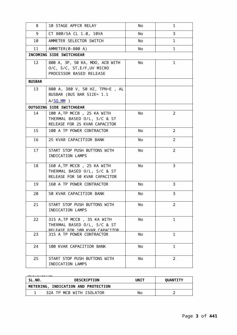
8 10 STAGE APFCR RELAY No 1
9 CT 800/5A CL 1.0, 10VA No 3
10 AMMETER SELECTOR SWITCH No 1
11 AMMETER(0-800 A) No 1INCOMING SIDE SWITCHGEAR
12 800 A, 3P, 50 KA, MDO, ACB WITH O/C, S/C, ST,E/F,UV MICRO PROCESSOR BASED RELEASE
No 1
BUSBAR
13 800 A, 380 V, 50 HZ, TPN+E , ALBUSBAR (BUS BAR SIZE= 1.1 A/SQ.MM )
OUTGOING SIDE SWITCHGEAR14 100 A,TP MCCB , 25 KA WITH
THERMAL BASED O/L, S/C & ST RELEASE FOR 25 KVAR CAPACITOR
No 2
15 100 A TP POWER CONTRACTOR No 2
16 25 KVAR CAPACITIOR BANK No 2
17 START STOP PUSH BUTTONS WITH INDICATION LAMPS
No 2
18 160 A,TP MCCB , 25 KA WITHTHERMAL BASED O/L, S/C & ST RELEASE FOR 50 KVAR CAPACITOR
No 3
19 160 A TP POWER CONTRACTOR No 3
20 50 KVAR CAPACITIOR BANK No 3
21 START STOP PUSH BUTTONS WITH INDICATION LAMPS
No 2
22 315 A,TP MCCB , 35 KA WITHTHERMAL BASED O/L, S/C & ST RELEASE FOR 100 KVAR CAPACITOR
No 1
23 315 A TP POWER CONTRACTOR No 1
24 100 KVAR CAPACITIOR BANK No 1
25 START STOP PUSH BUTTONS WITH INDICATION LAMPS
No 2
PANEL NO 4 415 V MAIN LT PANEL
SL.NO. DESCRIPTION UNIT QUANTITYMETERING, INDICATION AND PROTECTION
1 32A TP MCB WITH ISOLATOR No 2
SIGNATURE OF TENDERER WITH SEAL EMPLOYER
Page 3 of 441

2 20A TPN MCB No 63 4A SP MCB No 64 R,Y,B LED INDICATING LAMPS No 65 ON, OFF, TRIP INDICATING LAMP No 66 LOAD MANAGER (V,A,F,KW) No 27 2000/5A CT CL 1.0, 10VA No 68 2000/5A CT CL 1.0, 10VA No 29 APFCR RELAY No 2
INCOMING SIDE SWITCHGEAR
10 2000 A, 4P, 50 KA, MDO, ACB WITH O/C, S/C, ST,E/F,UV MICRO PROCESSOR BASED RELEASE
No 2
11 2000 A, 4P, 50 KA, MDO, ACB WITHOUT RELEASE ( BUS COUPLER)
No 1
KASCH KEY MECHANICAL INTERLOCKING(3 LOCKS + 2 KEYS)
BUSBAR
12 2000 A, 415 V, 50 HZ, TPN+E , AL BUSBAR (BUS BAR SIZE= 1.1 A/SQ.MM )
OUTGOING SIDE SWITCHGEAR
13 125 A,TPN MCCB , 25 KA No 714 250 A,TPN MCCB , 35 KA No 115 400 A,TPN MCCB , 45 KA No 716 630 A,TPN MCCB , 50 KA No 317 800 A, MDO,TPN, ACB , 50 KA No 118 1250 A, MDO, TPN, ACB , 50 KA No 3
PANEL NO 5 415 V , 1250 KVA T/F APFCR 500 KVAR PANEL 1
SL.NO. DESCRIPTION UNIT QUANTITYMETERING, INDICATION AND PROTECTION
1 4A SP MCB No 32 R,Y,B LED INDICATING LAMPS No 33 VOLTMETER SELECTOR SWITCH No 1
4 VOLTMETER (0-500 V) No 15 ON, OFF, TRIP INDICATING LAMP No 36 TIMER No 17 14 STAGE APFCR RELAY No 18 CT 1250/5A CL 1.0, 10VA No 39 AMMETER SELECTOR SWITCH No 110 AMMETER(0-1250A) No 1
INCOMING SIDE SWITCHGEAR
SIGNATURE OF TENDERER WITH SEAL EMPLOYER
Page 4 of 441

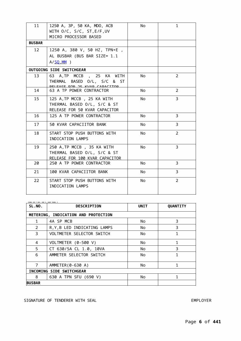
11 1250 A, 3P, 50 KA, MDO, ACB WITH O/C, S/C, ST,E/F,UV MICRO PROCESSOR BASED RELEASE
No 1
BUSBAR12 1250 A, 380 V, 50 HZ, TPN+E , AL
BUSBAR (BUS BAR SIZE= 1.1 A/SQ.MM )
OUTGOING SIDE SWITCHGEAR
13 63 A,TP MCCB , 25 KA WITH THERMAL BASED O/L, S/C & ST RELEASE FOR 25 KVAR CAPACITOR
No 2
14 63 A TP POWER CONTRACTOR No 215 125 A,TP MCCB , 25 KA WITH
THERMAL BASED O/L, S/C & ST RELEASE FOR 50 KVAR CAPACITOR
No 3
16 125 A TP POWER CONTRACTOR No 3
17 50 KVAR CAPACIITOR BANK No 3
18 START STOP PUSH BUTTONS WITH INDICATION LAMPS
No 2
19 250 A,TP MCCB , 35 KA WITHTHERMAL BASED O/L, S/C & ST RELEASE FOR 100 KVAR CAPACITOR
No 3
20 250 A TP POWER CONTRACTOR No 3
21 100 KVAR CAPACIITOR BANK No 3
22 START STOP PUSH BUTTONS WITH INDICATION LAMPS
No 2
PANEL NO 6 415 V , 1250 KVA T/F APFCR 500 KVAR PANEL 2
SL.NO. DESCRIPTION UNIT QUANTITYMETERING, INDICATION AND PROTECTION
1 4A SP MCB No 32 R,Y,B LED INDICATING LAMPS No 33 VOLTMETER SELECTOR SWITCH No 1
4 VOLTMETER (0-500 V) No 15 ON, OFF, TRIP INDICATING LAMP No 3
6 TIMER No 17 14 STAGE APFCR RELAY No 18 CT 1250/5A CL 1.0, 10VA No 39 AMMETER SELECTOR SWITCH No 1
10 AMMETER(0-1250A) No 1
SIGNATURE OF TENDERER WITH SEAL EMPLOYER
INCOMING SIDE SWITCHGEAR
Page 5 of 441
11 1250 A, 3P, 50 KA, MDO, ACB WITH O/C, S/C, ST,E/F,UV MICRO PROCESSOR BASED RELEASE
No 1
BUSBAR12 1250 A, 380 V, 50 HZ, TPN+E , AL
BUSBAR (BUS BAR SIZE= 1.1 A/SQ.MM )
OUTGOING SIDE SWITCHGEAR13 63 A,TP MCCB , 25 KA WITH THERMAL
BASED O/L, S/C & ST RELEASE FOR 25 KVAR CAPACITOR
No 2
14 63 A TP POWER CONTRACTOR No 2
15 125 A,TP MCCB , 25 KA WITHTHERMAL BASED O/L, S/C & ST RELEASE FOR 50 KVAR CAPACITOR
No 3
16 125 A TP POWER CONTRACTOR No 3
17 50 KVAR CAPACIITOR BANK No 3
18 START STOP PUSH BUTTONS WITH INDICATION LAMPS
No 2
19 250 A,TP MCCB , 35 KA WITHTHERMAL BASED O/L, S/C & ST RELEASE FOR 100 KVAR CAPACITOR
No 3
20 250 A TP POWER CONTRACTOR No 3
21 100 KVAR CAPACIITOR BANK No 3
22 START STOP PUSH BUTTONS WITH INDICATION LAMPS
No 2
PANEL NO 7 203, 380 V, SHOP PANEL 1
SL.NO. DESCRIPTION UNIT QUANTITY
METERING, INDICATION AND PROTECTION1 4A SP MCB No 32 R,Y,B LED INDICATING LAMPS No 33 VOLTMETER SELECTOR SWITCH No 1
4 VOLTMETER (0-500 V) No 15 CT 630/5A CL 1.0, 10VA No 36 AMMETER SELECTOR SWITCH No 1
7 AMMETER(0-630 A) No 1INCOMING SIDE SWITCHGEAR
8 630 A TPN SFU (690 V) No 1BUSBAR
SIGNATURE OF TENDERER WITH SEAL EMPLOYER
Page 6 of 441
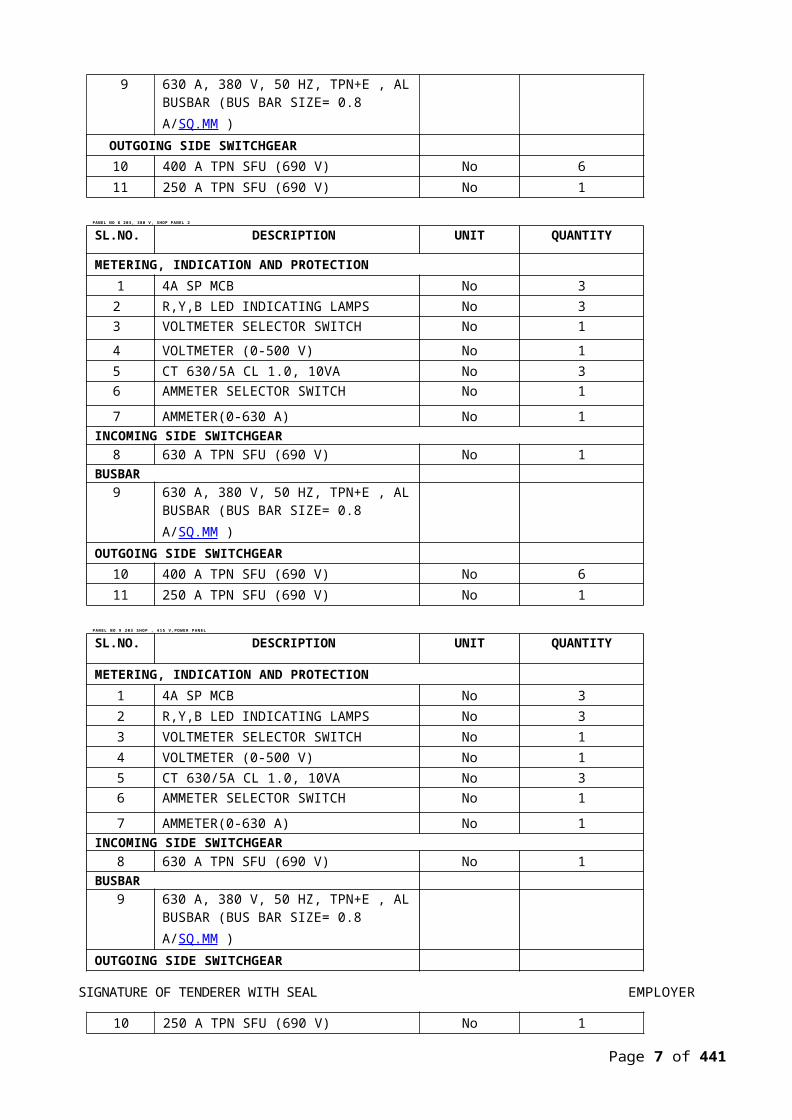
9 630 A, 380 V, 50 HZ, TPN+E , ALBUSBAR (BUS BAR SIZE= 0.8 A/SQ.MM )
OUTGOING SIDE SWITCHGEAR
10 400 A TPN SFU (690 V) No 611 250 A TPN SFU (690 V) No 1
PANEL NO 8 203, 380 V, SHOP PANEL 2
SL.NO. DESCRIPTION UNIT QUANTITY
METERING, INDICATION AND PROTECTION1 4A SP MCB No 3
2 R,Y,B LED INDICATING LAMPS No 33 VOLTMETER SELECTOR SWITCH No 1
4 VOLTMETER (0-500 V) No 15 CT 630/5A CL 1.0, 10VA No 36 AMMETER SELECTOR SWITCH No 1
7 AMMETER(0-630 A) No 1INCOMING SIDE SWITCHGEAR
8 630 A TPN SFU (690 V) No 1BUSBAR
9 630 A, 380 V, 50 HZ, TPN+E , ALBUSBAR (BUS BAR SIZE= 0.8 A/SQ.MM )
OUTGOING SIDE SWITCHGEAR10 400 A TPN SFU (690 V) No 611 250 A TPN SFU (690 V) No 1
PANEL NO 9 203 SHOP , 415 V,POWER PANEL
SL.NO. DESCRIPTION UNIT QUANTITY
METERING, INDICATION AND PROTECTION1 4A SP MCB No 32 R,Y,B LED INDICATING LAMPS No 33 VOLTMETER SELECTOR SWITCH No 14 VOLTMETER (0-500 V) No 15 CT 630/5A CL 1.0, 10VA No 36 AMMETER SELECTOR SWITCH No 1
7 AMMETER(0-630 A) No 1INCOMING SIDE SWITCHGEAR
8 630 A TPN SFU (690 V) No 1BUSBAR
9 630 A, 380 V, 50 HZ, TPN+E , ALBUSBAR (BUS BAR SIZE= 0.8 A/SQ.MM )
OUTGOING SIDE SWITCHGEAR
SIGNATURE OF TENDERER WITH SEAL EMPLOYER
10 250 A TPN SFU (690 V) No 1
Page 7 of 441

11 160 A TPN SFU (690 V) No 212 125 A TPN SFU (690 V) No 513 100 A TPN SFU (690 V) No 314 63 A TPN SFU (690 V) No 215 32 A TPN SFU (690 V) No 3
PANEL NO 10 203 SHOP , 27 V DC, LHS PANEL
SL.NO. DESCRIPTION UNIT QUANTITY
METERING, INDICATION AND PROTECTION1 4A DP MCB No 12 ON, OFF LED INDICATING LAMPS No 23 VOLTMETER (0-50 V) DC ANALOG
TYPENo 1
4 0-630 A DC ANALOH AMMETER WITH SHUNT COIL
No 1
INCOMING SIDE SWITCHGEAR5 630 A ,DP,DC ,SFU No 1
BUSBAR6 630 A, 27 V DC AL BUSBAR
OUTGOING SIDE SWITCHGEAR7 250 A ,DP ,DC, SFU No 7
PANEL NO 11 203 SHOP , 27 V DC, RHS PANEL
SL.NO. DESCRIPTION UNIT QUANTITY
METERING, INDICATION AND PROTECTION1 4A DP MCB No 1
2 ON, OFF LED INDICATING LAMPS No 2
3 VOLTMETER (0-50 V) DC ANALOG TYPE
No 1
4 0-630 A DC ANALOH AMMETER WITH SHUNT COIL
No 1
INCOMING SIDE SWITCHGEAR
5 630 A, DP, DC SFU No 1BUSBAR
6 630 A, 27 V DC AL BUSBAROUTGOING SIDE SWITCHGEAR
7 250 A, DP ,DC SFU No 7
PANEL NO 12 203 SHOP , HIGH FREQ AC , LHS PANEL
SL.NO. DESCRIPTION UNIT QUANTITY
SIGNATURE OF TENDERER WITH SEAL EMPLOYER
METERING, INDICATION AND PROTECTION1 4A SP MCB No 3
Page 8 of 441

2 R,Y,B LED INDICATING LAMPS No 33 VOLTMETER SELECTOR SWITCH No 1
4 VOLTMETER (0-300 V) No 1
5 CT 400/5A CL 1.0, 10VA No 36 AMMETER SELECTOR SWITCH No 1
7 AMMETER(0-400 A) No 1INCOMING SIDE SWITCHGEAR
8 400 A TPN SFU (690 V) No 1BUSBAR
9 400 A, 380 V, 50 HZ, TPN+E , ALBUSBAR (BUS BAR SIZE= 0.8 A/SQ.MM )
OUTGOING SIDE SWITCHGEAR10 200 A TPN SFU (690 V) No 7
PANEL NO 13 203 SHOP , HIGH FREQ AC , RHS PANEL
SL.NO. DESCRIPTION UNIT QUANTITY
METERING, INDICATION AND PROTECTION1 4A SP MCB No 32 R,Y,B LED INDICATING LAMPS No 33 VOLTMETER SELECTOR SWITCH No 1
4 VOLTMETER (0-300 V) No 15 CT 400/5A CL 1.0, 10VA No 36 AMMETER SELECTOR SWITCH No 1
7 AMMETER(0-400 A) No 1INCOMING SIDE SWITCHGEAR
8 400 A TPN SFU (690 V) No 1BUSBAR
9 400 A, 380 V, 50 HZ, TPN+E , ALBUSBAR (BUS BAR SIZE= 0.8 A/SQ.MM )
OUTGOING SIDE SWITCHGEAR10 200 A TPN SFU (690 V) No 7
PANEL NO 14 203 SHOP , 415 V ,LIGHTING PANEL
SL.NO. DESCRIPTION UNIT QUANTITY
METERING, INDICATION AND PROTECTION1 4A SP MCB No 32 R,Y,B LED INDICATING LAMPS No 33 VOLTMETER SELECTOR SWITCH No 1
SIGNATURE OF TENDERER WITH SEAL EMPLOYER
4 VOLTMETER (0-500 V) No 15 CT 400/5A CL 1.0, 10VA No 36 AMMETER SELECTOR SWITCH No 1
Page 9 of 441

7 AMMETER(0-400 A) No 1INCOMING SIDE SWITCHGEAR
8 400 A TPN MCCB (50 KA) No 1BUSBAR
9 400 A, 415 V, 50 HZ, TPN+E , ALBUSBAR (BUS BAR SIZE= 0.8 A/SQ.MM )
OUTGOING SIDE SWITCHGEAR10 100 A TPN SFU (690 V) TYPICAL No 7
11 63 A TPN SFU (690 V) TYPICAL No 4
12 32 A TPN SFU (690 V) TYPICAL No 1
PANEL NO 15 203 SHOP , 415 V , HVAC PANEL
SL.NO. DESCRIPTION UNIT QUANTITY
METERING, INDICATION AND PROTECTION1 4A SP MCB No 32 R,Y,B LED INDICATING LAMPS No 33 VOLTMETER SELECTOR SWITCH No 1
4 VOLTMETER (0-500 V) No 15 CT 1000/5A CL 1.0, 10VA No 36 AMMETER SELECTOR SWITCH No 1
7 AMMETER(0-1000 A) No 1INCOMING SIDE SWITCHGEAR
8 1000 A , MDO, TPN,ACB (50 KA) No 1
BUSBAR9 1000 A, 415 V, 50 HZ, TPN+E , AL
BUSBAR (BUS BAR SIZE= 0.8 A/SQ.MM )
OUTGOING SIDE SWITCHGEAR10 125 A TPN SFU (690 V) TYPICAL No 811 100 A TPN SFU (690 V) TYPICAL No 212 63 A TPN SFU (690 V) TYPICAL No 9
PANEL NO 16 202, 380 V, SHOP PANEL
SL.NO. DESCRIPTION UNIT QUANTITY
METERING, INDICATION AND PROTECTION1 4A SP MCB No 32 R,Y,B LED INDICATING LAMPS No 33 VOLTMETER SELECTOR SWITCH No 1
SIGNATURE OF TENDERER WITH SEAL EMPLOYER
4 VOLTMETER (0-500 V) No 15 CT 630/5A CL 1.0, 10VA No 36 AMMETER SELECTOR SWITCH No 1
7 AMMETER(0-630 A) No 1
Page 10 of 441

INCOMING SIDE SWITCHGEAR8 630 A TPN SFU (690 V) No 1
BUSBAR9 630 A, 380 V, 50 HZ, TPN+E , AL
BUSBAR (BUS BAR SIZE= 0.8 A/SQ.MM )
OUTGOING SIDE SWITCHGEAR10 400 A TPN SFU (690 V) No 611 250 A TPN SFU (690 V) No 2
PANEL NO 17 202 SHOP , 415 V ,POWER PANEL
SL.NO. DESCRIPTION UNIT QUANTITYMETERING, INDICATION AND PROTECTION
1 4A SP MCB No 32 R,Y,B LED INDICATING LAMPS No 33 VOLTMETER SELECTOR SWITCH No 1
4 VOLTMETER (0-500 V) No 15 CT 630/5A CL 1.0, 10VA No 36 AMMETER SELECTOR SWITCH No 1
7 AMMETER(0-630 V) No 1INCOMING SIDE SWITCHGEAR
8 630 A TPN SFU (690V) No 1BUSBAR
9 630 A, 415 V, 50 HZ, TPN+E , ALBUSBAR (BUS BAR SIZE= 0.8 A/SQ.MM )
OUTGOING SIDE SWITCHGEAR10 400 A TPN SFU (690 V) No 111 160 A TPN SFU (690 V) No 212 125 A TPN SFU (690 V) No 413 100 A TPN SFU (690 V) No 514 63 A TPN SFU (690 V) No 215 32 A TPN SFU (690 V) No 1
PANEL NO 18 202 SHOP , 27 V DC PANEL
SL.NO. DESCRIPTION UNIT QUANTITY
METERING, INDICATION AND PROTECTION1 4A DP MCB No 12 ON, OFF LED INDICATING LAMPS No 2
SIGNATURE OF TENDERER WITH SEAL EMPLOYER
3 VOLTMETER (0-50 V) DC ANALOG TYPE
No 1
4 0-630 A DC ANALOG AMMETER WITH SHUNT COIL
No 1
INCOMING SIDE SWITCHGEAR
Page 11 of 441

5 630 A DP DC SFU No 1
BUSBAR6 630 A, 27 V DC AL BUSBAR
OUTGOING SIDE SWITCHGEAR7 250 A DP DC SFU (TYPICAL ) No 78 160 A DP DC SFU (TYPICAL ) No 6
PANEL NO 19 202 SHOP , HIGH FREQ AC PANEL
SL.NO. DESCRIPTION UNIT QUANTITY
METERING, INDICATION AND PROTECTION1 4A SP MCB No 3
2 R,Y,B LED INDICATING LAMPS No 33 VOLTMETER SELECTOR SWITCH No 1
4 VOLTMETER (0-500 V) No 15 CT 400/5A CL 1.0, 10VA No 36 AMMETER SELECTOR SWITCH No 1
7 AMMETER(0-400 A) No 1INCOMING SIDE SWITCHGEAR
8 400 A TPN SFU (690 V) No 1BUSBAR
9 400 A, 380 V, 50 HZ, TPN+E , ALBUSBAR (BUS BAR SIZE= 0.8 A/SQ.MM )
OUTGOING SIDE SWITCHGEAR10 200 A TPN SFU (690 V) No 711 100 A TPN SFU (690 V) No 6
PANEL NO 20 202 SHOP ,415 V SOCKET BOARD PANEL
SL.NO. DESCRIPTION UNIT QUANTITY
METERING, INDICATION AND PROTECTION1 4A SP MCB No 32 R,Y,B LED INDICATING LAMPS No 33 VOLTMETER SELECTOR SWITCH No 1
4 VOLTMETER (0-500 V) No 15 CT 250/5A CL 1.0, 10VA No 36 AMMETER SELECTOR SWITCH No 1
7 AMMETER(0-400 A) No 1
INCOMING SIDE SWITCHGEAR
SIGNATURE OF TENDERER WITH SEAL EMPLOYER
9 400 A TPN SFU(690V) No 1BUSBAR
10 400 A, 415 V, 50 HZ, TPN+E , ALBUSBAR (BUS BAR SIZE= 0.8 A/SQ.MM )
OUTGOING SIDE SWITCHGEARPage 12 of 441

11 250 A TPN SFU (690 V) No 7
PANEL NO 21 202 SHOP , 415 V ,LIGHTING PANEL
SL.NO. DESCRIPTION UNIT QUANTITY
METERING, INDICATION AND PROTECTION1 4A SP MCB No 3
2 R,Y,B LED INDICATING LAMPS No 33 VOLTMETER SELECTOR SWITCH No 1
4 VOLTMETER (0-500 V) No 15 CT 400/5A CL 1.0, 10VA No 36 AMMETER SELECTOR SWITCH No 1
7 AMMETER(0-400 A) No 1INCOMING SIDE SWITCHGEAR
8 400 A TPN MCCB (50 KA) No 1BUSBAR
9 400 A, 415 V, 50 HZ, TPN+E , ALBUSBAR (BUS BAR SIZE= 0.8 A/SQ.MM )
OUTGOING SIDE SWITCHGEAR10 100 A TPN SFU (690 V) TYPICAL No 5
11 63 A TPN SFU (690 V) TYPICAL No 3
PANEL NO 23 201+209 SHOP, 380 V, SHOP PANEL
SL.NO. DESCRIPTION UNIT QUANTITY
METERING, INDICATION AND PROTECTION1 4A SP MCB No 32 R,Y,B LED INDICATING LAMPS No 33 VOLTMETER SELECTOR SWITCH No 1
4 VOLTMETER (0-500 V) No 15 CT 400/5A CL 1.0, 10VA No 36 AMMETER SELECTOR SWITCH No 1
7 AMMETER(0-400 A) No 1INCOMING SIDE SWITCHGEAR
8 400 A TPN SFU (690 V) No 1BUSBAR
SIGNATURE OF TENDERER WITH SEAL EMPLOYER
9 400 A, 380 V, 50 HZ, TPN+E , ALBUSBAR (BUS BAR SIZE= 0.8 A/SQ.MM )
OUTGOING SIDE SWITCHGEAR
10 400 A TPN SFU (690 V) No 311 250 A TPN SFU (690 V) No 112 125 A TPN SFU (690 V) No 113 100 A TPN SFU (690 V) No 1
Page 13 of 441
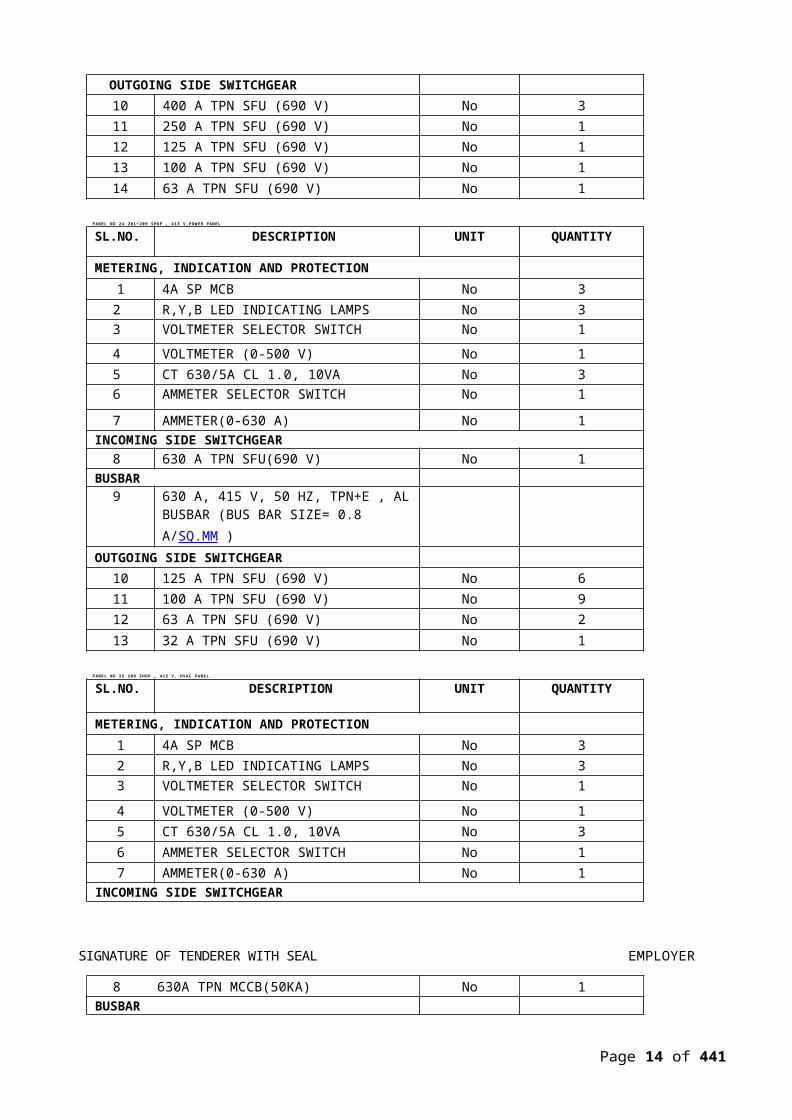
14 63 A TPN SFU (690 V) No 1
PANEL NO 24 201+209 SHOP , 415 V,POWER PANEL
SL.NO. DESCRIPTION UNIT QUANTITY
METERING, INDICATION AND PROTECTION1 4A SP MCB No 3
2 R,Y,B LED INDICATING LAMPS No 33 VOLTMETER SELECTOR SWITCH No 1
4 VOLTMETER (0-500 V) No 15 CT 630/5A CL 1.0, 10VA No 36 AMMETER SELECTOR SWITCH No 1
7 AMMETER(0-630 A) No 1INCOMING SIDE SWITCHGEAR
8 630 A TPN SFU(690 V) No 1BUSBAR
9 630 A, 415 V, 50 HZ, TPN+E , ALBUSBAR (BUS BAR SIZE= 0.8 A/SQ.MM )
OUTGOING SIDE SWITCHGEAR10 125 A TPN SFU (690 V) No 611 100 A TPN SFU (690 V) No 912 63 A TPN SFU (690 V) No 213 32 A TPN SFU (690 V) No 1
PANEL NO 25 209 SHOP , 415 V , HVAC PANEL
SL.NO. DESCRIPTION UNIT QUANTITY
METERING, INDICATION AND PROTECTION1 4A SP MCB No 32 R,Y,B LED INDICATING LAMPS No 33 VOLTMETER SELECTOR SWITCH No 1
4 VOLTMETER (0-500 V) No 15 CT 630/5A CL 1.0, 10VA No 36 AMMETER SELECTOR SWITCH No 17 AMMETER(0-630 A) No 1
INCOMING SIDE SWITCHGEAR
SIGNATURE OF TENDERER WITH SEAL EMPLOYER
8 630A TPN MCCB(50KA) No 1BUSBAR
9 630 A, 415 V, 50 HZ, TPN+E , ALBUSBAR (BUS BAR SIZE= 0.8 A/SQ.MM )
OUTGOING SIDE SWITCHGEAR10 100 A TPN SFU (690 V) TYPICAL No 4
11 63 A TPN SFU (690 V) TYPICAL No 9
Page 14 of 441

12 32 A TPN SFU (690 V) TYPICAL No 1
PANE L NO 27 201+209 SHO P , 415 V , L IG HTING PA NEL
SL.NO. DESCRIPTION UNIT QUANTITY
METERING, INDICATION AND PROTECTION1 4A SP MCB No 3
2 R,Y,B LED INDICATING LAMPS No 33 VOLTMETER SELECTOR SWITCH No 1
4 VOLTMETER (0-500 V) No 15 CT 400/5A CL 1.0, 10VA No 36 AMMETER SELECTOR SWITCH No 1
7 AMMETER(0-400 A) No 1INCOMING SIDE SWITCHGEAR
8 400A TPN MCCB (50 KA) No 1BUSBAR
9 400 A, 415 V, 50 HZ, TPN+E , ALBUSBAR (BUS BAR SIZE= 0.8 A/SQ.MM )
OUTGOING SIDE SWITCHGEAR10 100 A TPN SFU (690 V) TYPICAL No 7
11 63 A TPN SFU (690 V) TYPICAL No 3
12 32 A TPN SFU (690 V) TYPICAL No 1
PANEL NO 28 208(LOOM SECTION) SHOP , 415 V,POWER PANEL
SL.NO. DESCRIPTION UNIT QUANTITY
METERING, INDICATION AND PROTECTION1 4A SP MCB No 32 R,Y,B LED INDICATING LAMPS No 33 VOLTMETER SELECTOR SWITCH No 1
4 VOLTMETER (0-500 V) No 15 CT 630/5A CL 1.0, 10VA No 36 AMMETER SELECTOR SWITCH No 1
SIGNATURE OF TENDERER WITH SEAL EMPLOYER
7 AMMETER(0-400 A) No 1INCOMING SIDE SWITCHGEAR
8 400A TPN SFU (690 V) No 1BUSBAR
9 400 A, 415 V, 50 HZ, TPN+E , ALBUSBAR (BUS BAR SIZE= 0.8 A/SQ.MM )
OUTGOING SIDE SWITCHGEAR10 160 A TPN SFU (690 V) No 511 125 ATPN SFU (690 V) No 3
Page 15 of 441
12 100 A TPN SFU (690 V) No 213 63 A V TPN SFU (690 V) No 214 32 A V TPN SFU (690 V) No 1
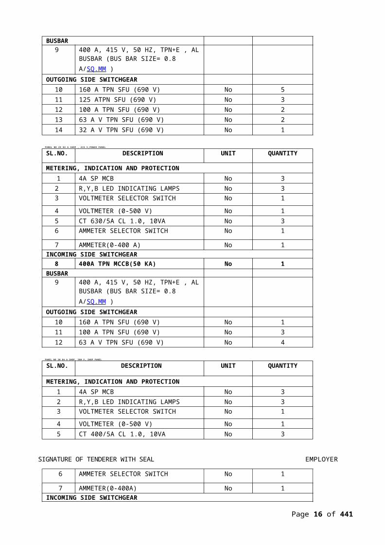
PANE L NO 29 84 A S HOP , 415 V ,POW ER PANEL
SL.NO. DESCRIPTION UNIT QUANTITY
METERING, INDICATION AND PROTECTION1 4A SP MCB No 3
2 R,Y,B LED INDICATING LAMPS No 33 VOLTMETER SELECTOR SWITCH No 1
4 VOLTMETER (0-500 V) No 15 CT 630/5A CL 1.0, 10VA No 36 AMMETER SELECTOR SWITCH No 1
7 AMMETER(0-400 A) No 1INCOMING SIDE SWITCHGEAR
8 400A TPN MCCB(50 KA) No 1BUSBAR
9 400 A, 415 V, 50 HZ, TPN+E , ALBUSBAR (BUS BAR SIZE= 0.8 A/SQ.MM )
OUTGOING SIDE SWITCHGEAR10 160 A TPN SFU (690 V) No 111 100 A TPN SFU (690 V) No 312 63 A V TPN SFU (690 V) No 4
PANEL NO 30 84 A SHOP, 380 V, SHOP PANEL
SL.NO. DESCRIPTION UNIT QUANTITY
METERING, INDICATION AND PROTECTION1 4A SP MCB No 32 R,Y,B LED INDICATING LAMPS No 33 VOLTMETER SELECTOR SWITCH No 1
4 VOLTMETER (0-500 V) No 15 CT 400/5A CL 1.0, 10VA No 3
SIGNATURE OF TENDERER WITH SEAL EMPLOYER
6 AMMETER SELECTOR SWITCH No 1
7 AMMETER(0-400A) No 1INCOMING SIDE SWITCHGEAR
8 400 A TPN SFU (690 V) No 1BUSBAR
9 400 A, 380 V, 50 HZ, TPN+E , ALBUSBAR (BUS BAR SIZE= 0.8 A/SQ.MM )
OUTGOING SIDE SWITCHGEAR10 250 A TPN SFU (690 V) No 111 100 A TPN SFU (690 V) No 1
Page 16 of 441

12 63 A TPN SFU (690 V) No 4
PANEL NO 32 AREA LIGHTING PANEL(WEATHER PROOF) 1
SL.NO. DESCRIPTION UNIT QUANTITY
METERING, INDICATION AND PROTECTION1 4A SP MCB No 3
2 R,Y,B LED INDICATING LAMPS No 33 VOLTMETER SELECTOR SWITCH No 1
4 VOLTMETER (0-500 V) No 15 CT 63/5A CL 1.0, 10VA No 36 AMMETER SELECTOR SWITCH No 1
7 AMMETER(0-63A) No 18 ON /OFF INDICATING LAMP No 2
INCOMING SIDE SWITCHGEAR9 63A TP MCB (40 KA) No 110 POWER CONTRACTOR 63 A No 111 24 HRS TIMER No 112 AUTO MANUAL SWITCH No 1
BUSBAR13 63 A, 415 V, 50 HZ, TPN+E , AL BUSBAR
(BUS BAR SIZE= 0.8 A/SQ.MM )
OUTGOING SIDE SWITCHGEAR14 16 A TPN 10 KA MCB No 9
PANEL NO 33 AREA LIGHTING PANEL(WEATHER PROOF) 2
SL.NO. DESCRIPTION UNIT QUANTITYMETERING, INDICATION AND PROTECTION
1 4A SP MCB No 32 R,Y,B LED INDICATING LAMPS No 33 VOLTMETER SELECTOR SWITCH No 1
4 VOLTMETER (0-500 V) No 1
SIGNATURE OF TENDERER WITH SEAL EMPLOYER
5 CT 63/5A CL 1.0, 10VA No 36 AMMETER SELECTOR SWITCH No 1
7 AMMETER(0-63A) No 18 ON /OFF INDICATING LAMP No 2
INCOMING SIDE SWITCHGEAR
9 63A TP MCB (40 KA) No 110 POWER CONTRACTOR 63 A No 111 24 HRS TIMER No 112 AUTO MANUAL SWITCH No 1
BUSBAR
Page 17 of 441

13 63 A, 415 V, 50 HZ, TPN+E , AL BUSBAR (BUS BAR SIZE= 0.8 A/SQ.MM )
OUTGOING SIDE SWITCHGEAR14 16 A TPN 10 KA MCB No 9
NOTES:1 ALL BUSBARS IN POWER HOUSE SHALL BE AL WITH 1.1 A/ SQ MM
CURRENT DENSITY
2 ALL BUSBARS IN SHOPS SHALL BE AL WITH 0.8 A/ SQ MM CURRENT DENSITY
3 BELOW 400A MCCBS SHALL BE WITH THERMAL MAGNETIC BASED O/L, S/C & ST RELEASES
4 400A TO 630A MCCBS SHALL BE WITH O/C, S/C, ST & E/F MICRO PROCESSOR BASED RELEASES
5 ABOVE 800A BREAKERS SHALL BE ACB WITH MICROPROCESSOR BASED WITH O/C, S/C, ST & E/F MICRO PROCESSOR BASED RELEASES
6 INCOMING ACBs IN MAIN LT PANEL ARE MECHANICALLY INTERLOCKED WITH KASCH KEY LOCKING SYSTEM WITH 3 LOCKS+ 2 KEYS.
LARGE SOCKET BOARD(FLOOR MOUNTED) LSB-The Large Socket Boards has 3 sections : one each for 380V, 50 Hz supply , High Frequency supply and 27 V DC supply. Note : To be read in conjunction with SLD
SL.NO. DESCRIPTION UNIT QUANTITY
380V, 50 HZ, 3 PHASE SIDE
METERING AND INDICATIONS1 4A SP MCB No 3
SIGNATURE OF TENDERER WITH SEAL EMPLOYER
2 R,Y,B LED INDICATING LAMPS No 3
3 VOLTMETER SELECTOR SWITCH No 1
4 VOLTMETER (0-500 V) No 1BUSBAR
5 400 A, 380 V, 50 HZ, TPN+E , AL BUSBAR (BUS BAR SIZE= 0.8 A/SQ.MM )
INCOMING SIDE SWITCHGEAR6 400 A TPN SFU (690 V) No 1
OUTGOING SIDE SWITCHGEARS
7 32 A DP MCB, 10 KA No 1
Page 18 of 441

8 40 A DP MCB, 10 KA No 29 16 A SPN MCB, 10 KA No 1
10 200 A, 4P MCCB, 10 KA No 1
11 125 A, TPN MCCB, 10 KA No 3
12 16 A SP MCB, 10 KA No 2
13 20 A SP MCB, 10 KA No 4
15 63 A, 4P MCB, 10 KA No 2
16 32 A, TP MCB, 10 KA No 2
TRANSFORMER17 230/24 V AC, 1 PHASE ,
500VATRANSFORMERNo 1
18 25 A FUSE BASE AND FUSE No 1
OUT GOING SOCKETS19 15 A , 3 PIN FLUSH MOUNTED SOCKET No 220 20 A , 3 PIN METAL CLAD SOCKET No 4
21 5 A , 2 PIN FLUSH MOUNTED SOCKET No 822 63 A ,3P+N+E METAL CLAD SOCKET No 223 32 A ,3P+E METAL CLAD SOCKET No 2
24 125 A ,3P+N+E METAL CLAD SOCKET No 3
HIGH FREQ SIDE
METERING AND INDICATIONS1 4A SP MCB No 3
2 LED INDICATING LAMPS No 3
3 VOLTMETER SELECTOR SWITCH No 1
4 VOLTMETER (0-300 V) No 1
INCOMING SIDE SWITCHGEAR
5 200 A, 4P MCCB, 40 KA No 1
BUSBAR
SIGNATURE OF TENDERER WITH SEAL EMPLOYER
6 200 A, 208 V, 400 HZ, TPN+E , AL BUSBAR (BUS BAR SIZE= 0.8 A/SQ.MM )
OUTGOING SIDE SWITCHGEAR AND SOCKET7 16 A DP MCB, 10 KA No 2
8 16 A, 5 PIN FLUSH MOUNTED SOCKET No 2
DC SIDEMETERING AND INDICATIONS
1 4A DP MCB No 12 ON, OFF INDICATING LAMP No 23 DC VOLTMETER (0-50 V) DC ANALOG
TYPENo 1
INCOMING SIDE SWITCHGEARPage 19 of 441

4 250 A, DP+E DC SFU No 1
BUSBAR5 250 A, 27 V DC, AL BUSBAR (BUS BAR
SIZE= 0.8 A/SQ.MM )OUTGOING SIDE SWITCHGEAR AND SOCKET
6 16 A DP DC MCB No 2
7 10 A 2 PIN NON REVERSIBLE MOULDED TYPE SOCKET
No 2
SMALL SOCKET BOARD TYPE-1
SL.NO. DESCRIPTION UNIT QUANTITY415V, 50 HZ, 3 PHASE SIDE
1 4A SP MCB No 32 R,Y,B LED INDICATING LAMPS No 33 VOLTMETER SELECTOR SWITCH No 14 VOLTMETER (0-500 V) No 1
INCOMING SIDE SWITCHGEAR5 100 A 4PMCB 25 KA No 1
BUSBAR6 100 A, 415 V, 50 HZ, TPN+E , AL BUSBAR
(BUS BAR SIZE= 0.8 A/SQ.MM )OUTGOING SIDE SWITCHGEARS
7 20 A DP MCB, 10 KA No 38 32 A, TP MCB No 29 16 A SPN MCB, 10 KA No 1
TRANSFORMER10 230/24 V AC, 1 PHASE , 500VA
TRANSFORMERNo 1
11 25 A, FUSE AND FUSE BASE No 1
OUTGOING SIDE SOCKETS
12 20 A ,3 PIN (P+N+E) METAL CLAD SOCKET
No 3
13 32 A ,3P+E METAL CLAD SOCKET No 2
14 5 A , 2 PIN FLUSH MOUNTED SOCKET No 2
HIGH FREQ SIDE
SIGNATURE OF TENDERER WITH SEAL EMPLOYERMETERING AND INDICATIONS
1 4A SP MCB No 32 R,Y,B LED INDICATING LAMPS No 33 VOLTMETER SELECTOR SWITCH No 14 VOLTMETER (0-300 V) No 1
INCOMING SIDE SWITCHGEAR5 63 A, 4P MCB, 16 KA No 1
BUSBAR6 63 A, 208 V, 400 HZ, TPN+E , AL BUSBAR
(BUS BAR SIZE= 0.8 A/SQ.MM )
OUTGOING SIDE SWITCHGEARS7 16 A DP MCB, 10 KA No 28 32 A, 4P MCB No 2
OUTGOING SIDE SOCKETSPage 20 of 441

9 16 A, 3 PIN FLUSH MOUNTED SOCKET No 210 32 A , 5 PIN INSULATED PLUG SOCKET
(3P+N+E)No 2
DC SIDEMETERING AND INDICATIONS
1 4A DP MCB No 12 INDICATING LAMP No 23 DC VOLTMETER (0-50 V) DC ANALOG
TYPENo 1
INCOMING SIDE SWITCHGEAR1 63, DP+E DC SFU No 1
BUSBAR
463 A, 27 V DC, AL BUSBAR (BUS BAR SIZE= 0.8 A/SQ.MM )
OUTGOING SIDE SWITCHGEARS AND SOCKETS5 16 A DP DC MCB No 36 10 A 2 PIN NON REVERSIBLE MOULDED
TYPE SOCKETNo 3
SMALL SOCKET BOARD TYPE-2
SL.NO. DESCRIPTION UNIT QUANTITYMETERING AND INDICATIONS
1 4A SP MCB No 32 R,Y,B LED INDICATING LAMPS No 33 VOLTMETER SELECTOR SWITCH No 14 VOLTMETER(0-500 V) No 1
INCOMING SIDE SWITCHGEAR5 63 A 4P MCB 25 KA No 1
BUSBAR6 63 A, 415 V, 50 HZ, TPN+E , AL BUSBAR
(BUS BAR SIZE= 0.8 A/SQ.MM )OUTGOING SIDE SWITCHGEAR
7 20 A DP MCB, 10 KA No 28 32 A, TP MCB No 19 15 A SPN MCB, 10 KA No 1
TRANSFORMER
SIGNATURE OF TENDERER WITH SEAL EMPLOYER
10 230/24 V AC, 1 PHASE ,100VATRANSFORMER
No 1
11 5 A, FUSE AND FUSE BASE No 1OUTGOING SIDE
SOCKETS12 20 A ,3 PIN (P+N+E) METAL CLAD SOCKET
No 2
13 32 A ,3P+E METAL CLAD SOCKET No 114 5 A , 2 PIN FLUSH MOUNTED SOCKET No 2
SMALL SOCKET BOARD TYPE-3
SL.NO. DESCRIPTION UNIT QUANTITYMETERING AND INDICATIONS
1 4A SP MCB No 32 R,Y,B LED INDICATING LAMPS No 33 VOLTMETER SELECTOR SWITCH No 1
Page 21 of 441

4 VOLTMETER (0-500 V) No 1INCOMING SIDE SWITCHGEAR
5 100 A 4P MCB 25 KA No 1BUSBAR
6 100 A, 415 V, 50 HZ, TPN+E , AL BUSBAR (BUS BAR SIZE= 0.8 A/SQ.MM )
OUTGOING SIDE SWITCHGEAR7 20 A DP MCB, 10 KA No 28 32 A, TP MCB No 19 16 A SPN MCB, 10 KA No 1
TRANSFORMER10 230/24 V AC, 1 PHASE ,
200VATRANSFORMERNo 1
11 5 A, FUSE AND FUSE BASE No 1OUTGOING SIDE SOCKETS
12 20 A ,3 PIN (P+N+E) METAL CLAD SOCKET
No 2
13 32 A ,3P+E METAL CLAD SOCKET No 114 15 A , 2 PIN FLUSH MOUNTED SOCKET No 2
PREAMBLE TO BILL OF QUANTITIES
1. System / Installation covered under this tender broadly identified as follows:- Electrical system (including earthing & lighting protection, telephone/data cabling for
Overhaul Hangari) a) Shop No 201 : Dismantling shop
b) Shop No 202 : Shop for Overhauling & Assembly of Aggregatesc ) Shop No 203 : Assemb ly Shopd) Shop No 209 : Shop for removal of paint & varnish
ii) Fuel Aggregates Washing and Testing (084 a)
- Electrical system required for Air Conditioning and Ventilation for Overhaul shopsand Fuel Aggregates Washing and Testing (084 a) shop
- Street Lighting for New Hangar/Shops area
SIGNATURE OF TENDERER WITH SEAL EMPLOYER
- HT Substation
2. Scope of works covered under this tender shall be supply of necessary equipments, installation,erection, testing and commissioning of the system. The skilled & unskilled laborers, lifting tools and tackle and any other materials and equipments that may be required will be provided by the Contractor. The actual extent of work vis-à-vis the distribution system shall be as indicated in the drawings / specifications released for construction.
3. Following, but not limited to, shall be in the scope of the Contractor and quoted rates shall bedeemed to be inclusive of the cost for the same :a) Supply of all equipments / materials / accessories / consumables / hardware.
b) Packing and forwarding of above
c) Obtaining test certificates from approval test laboratories / authorities for the components
Page 22 of 441
before assembly of panels / equipments etc
d) Arranging shop inspection for items / equipments as stipulated in the specification.
e) Transporting to sire, receiving at site, and unloading and proper storage at site
f) Inspection at site on receipt. periodic inspection and maintaining in proper condition during storage at site.
g) Transporting from stores to extract location of installation.
h) Obtaining approvals (both pre and post construction) from Statutory Authorities
i) Positioning, aligning , fixing, assembly and installing of items after carrying out proper cleaning and inspection.
j) Site supervision, testing for proper functioning/operation and pre-commissioning tests.
k) Removing dents / bends etc if found and bringing to original condition and touch up paints for scratches if any.
l) Commissioning after all site test and obtaining approval from Central Electricity Authority.
m) Operation of instal lat ion on load.
n) Obtaining and maintaining comprehensive storages cum erection including living / non living, third party liabilities.
o) Final handing over of instal lat ion
p) Preparation of shop drawings/ cable or conduit layout drawing / working details based ion drawing issued by the Consultant / Client and site conditions and obtaining approval of the same from the Consultant before commencement of work.
q) Preparation of Final As- built drawings.
r ) Commiss ion ing o f the Sys tem
4. HAL reserves the right to procure LT panels or low voltage systems or any other electrical itemsseparately for economic reasons. Final decision on the same will be conveyed to the successful bidder after price bid opening
SIGNATURE OF TENDERER WITH SEAL EMPLOYER
5. It shall be the contractor’s responsibility to cleat the site of the employer’s material for which contractor will provide his labor and supervision at no extra cost to Employer. However, Employer will arrange transport to shift Employer’s material to a different location within the factory area as decided by the Site- in –charge.
6. The Contractor has to carry out his work according to Drawings, Specifications and Bill of Quantities
7. The tenderer should study the various items of the Bill of Quantities in conjunction with the Technical Data and Specifications as well as General instruction as given here.
8. The rates quoted herein shall be for complete work, labors, materials and incidentals and all taxes, duties, Octori and other duties and all other cost, insurance packing and freight and shall be rates at site
Page 23 of 441

of work.
9. No change in drawing, design, bill of quantities and specification shall be carried out unless the same is approved by the Consultant/HAL in writing.
10. Quantities mentioned are approximate and are subject to variation as require for final execution. The Employer reserves the right to increases or decrease the quantity of work
11. The privilege of authorship and ownership of drawings and designs remains with the Consultant. The drawings and designs prepared by the Consultant shall be used only for the purpose specified in this Contract and all drawings issued shall be returned on completion of work.
12. The Engineer, authorized by the Employer to represent at site-of-work, is authorized to ask the Contractor to discontinue any work which does not meet the expected and/or specified requirement and/or work already executed, may be rejected and asked to be removed for the same reason.
13. In the event of any discrepancy between the details on the drawings, description in the technical specifications and in the Bill of Quantities, then the item shall be deemed to have priced in accordance with the Bill of Quantities.
14. The rates quoted shall be for the complete item executed in a proper workman like manner.
15. Tenderers are required to study the various items very carefully & incase of any doubt clarification should be obtained from the Employer / Consultant before submitting the bid.
1.1 SCOPE OF THE WORK:
Scope of work covered under this tender shall be supply of the necessary equipment, installation, erection, testing and commissioning of the system. The skilled and unskilled labours as also lifting tools and tackle and any other materials and equipment that may be required will be provided by the Contractor. The actual extent of work vis-à-vis the distribution system shall be as indicated in the drawings/specifications, but not limited to following :
SIGNATURE OF TENDERER WITH SEAL EMPLOYER
a) Installation (Erection) only of 11 kV, 5 Module Indoor, VCB HT panels to receive powerwith CT & PT & metering.
b) Installation (Erection) only of 2 Nos. 1250 kVA, 11 kV / 433 V oil cooled type indoortransformers with OLTC, RTCC, AVR etc, 1 No of 1000 kVA, 11kV / 380V oil cooled type indoor transformers with OLTC, RTCC, AVR etc
c) Supply, installation, testing and commissioning of Power distribution boards, Power &Control cables, Terminations of cables, Cable trays etc.
d) Supply, installation testing and commissioning of Socket DB’s, Power socket outlets,Isolators, Small socket board’s (SSB’s) etc.
e) Supply, installation, testing and commissioning of Automatic Power Factor ImprovementPanel and Capacitors.
Page 24 of 441

g) Supply, installation, testing and commissioning of Earthing system and Lightningprotection system
h) Supply, installation, testing and commissioning of HT and LT power cables and controlcables.
i) Supply, installation, testing and commissioning of wiring for Telephone system and LANsystem , LAN equipments, PA system etc.
j) Final Commissioning of the system
1.2 GENERAL CONDITION
a The Specification and the Drawings are complementary and any item which is describedin the Specification and not shown on the Drawings, or vise versa, and is necessary or incidental to the electrical work must be furnished and installed within the Contract.
b HAL reserves the right to procure LT panels or low voltage systems or any otherelectrical items separately for economic reasons. Final decision on the same will be conveyed to the successful bidder after price bid opening
1.3 QUALITY OF MATERIALS & GENERAL STANDARDS OF WORK
SIGNATURE OF TENDERER WITH SEAL EMPLOYER
The contractor should commit himself to use materials listed under "APPROVED MAKE" only. Materials, equipments, fittings, etc. used in the installation shall conform to the latest relevant IS. In case of materials for which standard specifications do not exist, the Consultant / Client shall approve the material before start of work.
Also the contractor should full responsibility for the quality of all material incorporated brought for incorporation in the work. The work shall be executed in accordance with Engineering Practice and as per directions of Consultants.
1.4 CODE, REGULATIONS AND STANDARDS:
The particular specification for the work is as detailed hereinafter. These shall be read in conjunction with the relevant Indian Standard, Indian Electricity Rules Safety Codes, Chief fire officer’s recommendations and the obtainable local practice as detailed in various regional handbooks of practice and the work shall be executed accordingly. Wherever this specification calls for a higher standard of materials and/or workmanship then those required by any of the above regulations, this specification shall take precedence over the said Regulations and
Page 25 of 441

Standards.
In general, the materials, equipments and workmanship not covered by the above shall conform to the following Indian Standards (latest), unless otherwise called for. Nothing in the enclosed specification shall be construed to relieve the contractor of this responsibility.
Classification of degrees of protection provided by enclosures of electrical equipment
12063:1987 06
Electro-technical vocabulary: Part 8 Secondary cells and batteries (first revision) (Superseding IS:1174)
1885 (Part 8): 1986 04
Electro-technical vocabulary: Part 9 Electrical relays (Second revision of IS:1885)
1885 (Part 9): 1992 07
Electro-technical vocabulary: Part 10 Power system protection (first revision of IS 1885)
1885 (Part 10): 1993 03
Electro-technical vocabulary: Part 11 Electrical measurements 1885 (Part 11): 1966 09
Electro-technical vocabulary: Part 16 Lighting, Section 2 General 1885 (Part 16- Section
illumination, lighting fittings and lighting and traffic and signaling. 3): 1967 10
Electro-technical vocabulary: Part 17 Switchgear and control gear (first 1885 (Part 17): 1979 revision)
08
Electro-technical vocabulary: Part 28 Instrument transformers (first revision of IS 1885)
1885 (Part 28): 1992 04
Electro-technical Vocabulary: Part 32 Electric cables (first revision of 1885 (Part 32): 1992 05
IS 1885)
Electro-technical vocabulary: Part 38 Transformers (first edition) 1885 (Part 38): 1977 05
Electro-technical vocabulary: Part 42 Power Capacitors (second revision of IS 1885)
1885 (Part 42): 1992 04
SIGNATURE OF TENDERER WITH SEAL EMPLOYER
Electro-technical vocabulary: Part 54 Insulators (First revision of IS 1885 (Part 54): 1993 031885)
Electro-technical vocabulary: Part 55 Electric fans 1885 (Part 55): 1981 03
Page 26 of 441

Electro-technical vocabulary: Part 69 Generation, transmission and distribution of electricity – Generation
Electro-technical vocabulary: Part 71 Generation, transmission and distribution of electricity Substation
Graphical symbols for diagrams in the field of electro-technology: Part 3 Conductors and connecting devices
Graphical symbols for diagrams in the field of electro technology: Part7 Switchgear, control gear and protective devices.
Graphical symbols for diagrams in the field of electro technology: Part8 Measuring instruments, lamps and signaling devices.
Project : "Civil, Electrical and other utility services for package -Civil- III (Overhaul complex)VOLUME —II. TECHNICAL SPECIFICATIONS FOR TENDER NO.NK/FW/CAP-ROH-622/2010-11
Page 27 of 441
1885 (Part 69): 1993 04
1885 (Part 71): 1993 06
12032 (Part 3): 1987 05
12032(Part 7): 1987 12
12032(Part 8): 1987 07

Guide for color coding of electrical mimic diagrams 11954:1987 02
Guide for preparation of diagrams, charts and tables for electro 8207(Part I): 1976 02technology: Part 1 Definitions and classification.
AC supplied electronic ballasts for tubular florescent lamps: Part I, 13021(Part 2): 1991 05General and safety requirements.
Ballasts for high pressure mercury vapor lamps (first revision) 6616:1982 08
Bayonet lamp holders (third revision)(with amendment no.2) 1258:2005
High pressure mercury vapor lamps 9900(Part 1 to 4): 1981
Code of practice for Earthing 3043:1987
Code of practice for electrical wiring installations (third revision) 732:1989
Code of practice for the installation of electric bells and call system 8916:58:03
Code of practice for the protection of buildings and allied structures 2309: 1989against lighting (second revision)
Danger notice plates (first revision) 2551:1982
Project : "Civil, Electrical and other utility services for package -Civil- III (Overhaul complex)VOLUME —II. TECHNICAL SPECIFICATIONS FOR TENDER NO.NK/FW/CAP-ROH-622/2010-11
Page 28 of 441
Guide for improvement of power factor in consumer installation Part I, Low and medium supply voltages
Guide for safety procedures and practices in electrical work: Part 1, General (first revision)
Guide for safety procedures and practices in electrical work: Part 2, Life saving techniques (first revision)
Guide for short-circuit current calculations in three-phase AC system, (Superseding of IS5728:1970)
7752 (Part I): 1982 06
5216-1969(Part 1): 1982
5216(Part 2): 1982
13234:1992/I EC 909- 1986
Project : "Civil, Electrical and other utility services for package -Civil- III (Overhaul complex)VOLUME —II. TECHNICAL SPECIFICATIONS FOR TENDER NO.NK/FW/CAP-ROH-622/2010-11
Page 29 of 441

SIGNATURE OF TENDERER WITH SEAL EMPLOYER
Project : "Civil, Electrical and other utility services for package -Civil- III (Overhaul complex)VOLUME —II. TECHNICAL SPECIFICATIONS FOR TENDER NO.NK/FW/CAP-ROH-622/2010-11
Page 30 of 441

Special publication - National Electrical Code 30:1984
Special publication Chart on treatment for electric shock 31:1986
Warning symbol for dangerous voltages 8923:1978 01
Accessories for rigid steel conduits for electrical wiring (first revision) 3837:1976 04
Adaptors for flexible steel conduits 4649:1968 03
Appliance-connectors and appliance-inlets (non-reversible three-pin type): Part 1, Appliance connectors (with amendment No.6)
Boxes for enclosure of the electrical accessories: Part 1, Steel and cast iron box (with amendment No.2)
Boxes for the enclosure of electrical accessories: Part 2, Boxes made of insulating material
3010(Part 1): 1965 05
5133(Part 1): 1969 03
5133(Part 2): 1969 03
Ceiling roses (second revision) (with amendment No.4) 371:1979
Conduits for electrical installations: Part I, General requirements 9537(Part 1): 1981
Conduits for electrical installations: Part 3, Rigid plain conduits of 9537(Part 3): 1983insulating materials.
Conduits for electrical installation: Part 2, Rigid steel conduits (sup 9537(Part 2): 1981
Fittings for rigid non-metallic conduits (second revision) 3419:1988
Fittings for rigid steel conduits for electrical wiring (first revision) 2667:1988
Interlocking switch socket outlet 4160:2005
Plugs and socket outlets of rated voltage up to and including 250 volts 1293:2005 and rated current up to and including 16 Amps (third revision)
AC electricity meters: Part 3, Three-phase whole current and 722(Part 3): 1977 03transformer operated and single-phase transformer operated watt-hour meters, class 2(Second revision)(with amendment No.2)
AC electricity meters: Part 5, Volt-ampere hour meters for restricted 722(Part 5): 1980 05power factor range, class 3.5 (first revision) (with amendment No.2)
Guide for testing, calibration and maintenance of AC electricity meters: 9792(Part 1): 1987 06 Part 1, Single phase whole current watt hour meters, Class 2.0 (firstrevision)
Maximum Demand indicators (class 1) 8530:1977 04
Testing equipment for AC electrical energy meters 12346:1988 05
Application guide for the selection of High Voltage fuses for 12567:08:02transformer circuit applications.
SIGNATURE OF TENDERER WITH SEAL EMPLOYER
Project : "Civil, Electrical and other utility services for package -Civil- III (Overhaul complex)VOLUME —II. TECHNICAL SPECIFICATIONS FOR TENDER NO.NK/FW/CAP-ROH-622/2010-11
Page 31 of 441

Carriers and bases used in rewirable type electric fuses for voltages 2086:1993 up to 650 V (third revision)
High voltage fuses: Part 2, Current limiting fuses. 9385 (Part I): 1980
High Voltage fuses: Part 3, Application guide for high voltage fuses. 9385 (Part 3): 1980
Project : "Civil, Electrical and other utility services for package -Civil- III (Overhaul complex)VOLUME —II. TECHNICAL SPECIFICATIONS FOR TENDER NO.NK/FW/CAP-ROH-622/2010-11
Page 32 of 441
LV Fuses for voltages not exceeding 1000 V AC or 1500 V DC: Part I, General requirements
LV Fuses for voltages not exceeding 1000 V AC or 1500 V DC: Part 2, fuses for use by authorized persons, Section 1, Supplementary requirements
Specifications for LV Fuses for voltages not exceeding 1000 V AC or 1500 V DC
Project : "Civil, Electrical and other utility services for package -Civil- III (Overhaul complex)VOLUME —II. TECHNICAL SPECIFICATIONS FOR TENDER NO.NK/FW/CAP-ROH-622/2010-11
Page 33 of 441
13703(Part 1): 1993/ I EC
269-1(1986) 15
13703(Part 2-Section 1): 1993/IEC-269-2(1993)
13703(Part 1 to 4) 1993
Application guide for measuring devices for high voltage testing 8722:57:09
Methods of high voltage testing: Part 1, General definitions and test 2071(Part 1): 1993requirements, (first revision) (Superseding IS: 2070-1972)
AC contactors of voltage above 1000 V up to and including 11000 V 9046:1978 08
Alternating current dis-connectors (isolators) and Earthing switches for 9921(Part 1): 1981 voltage above 1000 V: Part 1 -General and definitions.
Alternating current dis-connectors (isolators) and Earthing switches for 9921(Part 2): 1982 voltage above 1000 V: Part 2 -Rating.
Alternating current dis-connectors (isolators) and Earthing switches for 9921(Part 3): 1982 voltages above 1000 V: Part 3- Design and construction
Alternating current dis-connectors (isolators) and Earthing switches for 9921(Part 4): 1985 voltages above 1000 V: Part 4- Type tests and routine tests.
Alternating current dis-connectors (isolators) and Earthing switches for 9921(Part 5): 1985 voltages above 1000 V: Part 5- Information to be given with tenderenquiries and orders
Dimensions of terminals of high voltage switchgear and control gear. 10634:03:00
General requirements for circuit breakers for voltages above 1000 V.
13118:1991
General requirements for switchgear and control gear for voltages exceeding 1000 V
Guide for testing of circuit breakers with respect to out-of-phase switching.
Interconnecting bus bars for AC voltage above 1 kV up to and including 36 kV
12729:1988
9135:1979
8116:56:00
SIGNATURE OF TENDERER WITH SEAL EMPLOYER
Project : "Civil, Electrical and other utility services for package -Civil- III (Overhaul complex)VOLUME —II. TECHNICAL SPECIFICATIONS FOR TENDER NO.NK/FW/CAP-ROH-622/2010-11
Page 34 of 441
Metal-enclosed switchgear and control gear for voltage above 1000 V 3459:49:00 but not exceeding 11000 volts (with amendment No.1)
Methods of synthetic testing of high voltage alternating current circuit 13549:13:00 breakers.
Switches and switch isolators for voltages above 1000V: Part 1 9920(Part 1): 1981General and definitions.
Switches and switch isolators for voltages above 1000V: Part 3 Design 9920(Part 3): 1982 and Construction
Application guide for voltage transformers (first revision) 4146:1993
Project : "Civil, Electrical and other utility services for package -Civil- III (Overhaul complex)VOLUME —II. TECHNICAL SPECIFICATIONS FOR TENDER NO.NK/FW/CAP-ROH-622/2010-11
Page 35 of 441
Current transformers: Part 1, General requirements (second revision)
Current transformer: Part 2, Measuring current transformers (second revision)
Current transformers: Part 3, Protective current transformers (second revision)
Current transformer: Part 4, Protective current transformers for special purpose applications (Second revision)
Voltage transformers: Part 1, General requirements (second revision)
Voltage transformers: Part 2, Measuring voltage transformers (second revision)
Voltage transformers: Part 3, Protective voltage transformers (second revision)
Voltage transformers: Part 4, Capacitor voltage transformer (second revision)
Circuit Breakers for over current protection for household and similar installations (first revision)
Code of practice for selection, installation and maintenance of switchgear and control gear(superseding IS 3072-75 & 3106-66): Part 1- General
Code of practice for selection, installation and maintenance of switchgear and control gear(superseding IS 3072-75 & 3106-66): Part2 - Selection
Code of practice for selection, installation and maintenance of switchgear and control gear(superseding IS 3072-75 & 3106-66): Part3 - Installation.
Code of practice for selection, installation and maintenance of switchgear and control gear(superseding IS 3072-75 & 3106-66): Part4 – Maintenance
Project : "Civil, Electrical and other utility services for package -Civil- III (Overhaul complex)VOLUME —II. TECHNICAL SPECIFICATIONS FOR TENDER NO.NK/FW/CAP-ROH-622/2010-11
Page 36 of 441
2705(Part 1): 1992
2705(Part 2): 1992
2705(Part 3): 1992
2705(Part 4): 1992
3156(Part 1): 1992
3156(Part 2): 1992
3156 (Part 3): 1992
3156(Part 4): 1992
8861:13:00
10118(Part 1): 1982
10118(Part 2): 1982
10118(Part 3): 1982
10118(Part 4): 1982

SIGNATURE OF TENDERER WITH SEAL EMPLOYER
Project : "Civil, Electrical and other utility services for package -Civil- III (Overhaul complex)VOLUME —II. TECHNICAL SPECIFICATIONS FOR TENDER NO.NK/FW/CAP-ROH-622/2010-11
Page 37 of 441
Identification of terminals of contactors and associated overload relays 10738:03:00
LV switchgear and control gear, Part I - General rules 13947(Part 1): 1993
LV switchgear and control gear, Part 2 -Circuit breakers 13947(Part 2): 1993
Project : "Civil, Electrical and other utility services for package -Civil- III (Overhaul complex)VOLUME —II. TECHNICAL SPECIFICATIONS FOR TENDER NO.NK/FW/CAP-ROH-622/2010-11
Page 38 of 441

LV switchgear and control gear Part 3, Switches, dis-connectors, switch dis-connectors and fuse combination unit
LV switchgear and control gear Part 4, Contactors and motor starters Section 1, Electromechanical
LV switchgear and control gear Part 5, Control circuit devices and switching elements, Section 1 Electromechanical control device (All parts)}
Miniature circuit breaker boards for voltage up to and including 1000 volts AC.
Specification for low voltage switchgear and control gear assemblies: Part 1, Requirements for type-tested and partially type tested assemblies (first revision)
Specification for low voltage switchgear and control gear assemblies: Part 2, Particular requirements for bus bar trunking systems (bus ways) (first revision)
LV Switchgear and control gear assemblies: Part 3, Particular requirements for equipment where unskilled persons have access for their use.
Project : "Civil, Electrical and other utility services for package -Civil- III (Overhaul complex)VOLUME —II. TECHNICAL SPECIFICATIONS FOR TENDER NO.NK/FW/CAP-ROH-622/2010-11
Page 39 of 441
13947(Part 3): 1993
13947(Part 4)-section 1): 1993
13947(Part 5)-Section 1): 1993
13065:11:00
8623(Part 1): 1993
8623(Part 2): 1993
8623(Part 3): 1993

Brass glands for PVC cables 12943:1990
Project : "Civil, Electrical and other utility services for package -Civil- III (Overhaul complex)VOLUME —II. TECHNICAL SPECIFICATIONS FOR TENDER NO.NK/FW/CAP-ROH-622/2010-11
Page 40 of 441

Cast iron joints boxes for tee and branch trouser joints suitable for paper insulated cables for voltages up to and including 11 kV.
Code of practice for installation and maintenance of power cables up to and including 33 kV rating (second revision)
Compression type tubular in-line connectors for aluminum conductors of insulated cables (first revision)
Compression type tubular terminal ends for aluminum conductors of insulated (with amendment No.1)
Conductors for insulated electric cables and flexible cords (first revision)
Cross linked polyethylene insulated PVC sheathed cables: Part 1 for working voltage up to and including 1100 V (Second revision)
Project : "Civil, Electrical and other utility services for package -Civil- III (Overhaul complex)VOLUME —II. TECHNICAL SPECIFICATIONS FOR TENDER NO.NK/FW/CAP-ROH-622/2010-11
Page 41 of 441
10639:03:00
1288:03:00
8341:13:00
8342:13:00
8163:04:00
7098(Part 1): 1988

SIGNATURE OF TENDERER WITH SEAL EMPLOYER
Project : "Civil, Electrical and other utility services for package -Civil- III (Overhaul complex)VOLUME —II. TECHNICAL SPECIFICATIONS FOR TENDER NO.NK/FW/CAP-ROH-622/2010-11
Page 42 of 441

Cross linked polyethylene insulated PVC sheathed cables: Part 2 for 7098(Part 2): 1985 working voltage from 3.3 kV up to and including 33 kV (first revision)
Drums for electric cables. 10418:1982
Methods of test for cables : Part 0, General 10810(Part 0): 1984
PVC insulated cables for working voltages up to and including 1100 V 694:1990 (Third revision)
Application guide for electrical relays for AC systems: Part 1, Over 3842(Part 1): 1967current relays for feeders and transformers
Application guide for electrical relays for AC systems: Part 2, Over 3842(Part 2): 1966current relays for generators and motors
Application guide for electrical relays for AC systems: Part 3, Phase 3842(Part 3): 1966unbalance relays including negative phase sequence relays (withamendment No.1)
Application guide for electrical relays for AC systems: Part 4, Thermal 3842(Part 4): 1966 relays (with amendment No.1)
Application guide for electrical relays for AC systems: Part 5, Distance 3842(Part 5): 1968 protection relays
Application guide for electrical relays for AC systems: Part 6, Power 3842(Part 6): 1972relays.
Application guide for electrical relays for AC systems: Part 7) 3842(Part 7): 1972Frequency relays.
Application guide for electrical relays for AC systems: Part 8, Voltage 3842(Part 8): 1976 relays.
Application guide for electrical relays for AC systems: Part 9, Relays 3842(Part 9): 1977 for bus bar protection.
Application guide for electrical relays for AC systems: Part 10, Relays 3842(Part 10): 1976 for transverse differential protection
Application guide for electrical relays for AC systems: Part 12, 3842(Part 12): 1976Differential relays for transformers.
Specification for electrical relays for power system protection (with 3231(Part 0): 1986amendment No.4)
Application guide for on-load tap changers 8478:1977
Application guide for power transformers 10561:1983
SIGNATURE OF TENDERER WITH SEAL EMPLOYER
Project : "Civil, Electrical and other utility services for package -Civil- III (Overhaul complex)VOLUME —II. TECHNICAL SPECIFICATIONS FOR TENDER NO.NK/FW/CAP-ROH-622/2010-11
Page 43 of 441
Cable sealing boxes for oil immersed transformers suitable for paper 9147:1979 insulated lead sheathed cables for highest system voltages from 12 kVup to and including 36 kV.
Code of practice for selection, installation and maintenance of 10028(Part 1): 1985transformers: Part 1- Selection.
Code of practice for selection, installation and maintenance of 10028(Part II): 1981transformers: Part 2- Installation (Superseding IS:1886)
Outdoor type three-phase distribution transformers up to and including 1180(Part I): 1989 100kVA,11kV, Part 1 - Non-sealed type
Outdoor type three-phase distribution transformers up to and including 1180(Part II): 1989 100kVA,11kV:Part II - Sealed type
Power transformers: Part 1, General (First revision) 2026(Part I): 1977
Flame proof enclosures of electrical apparatus (First revision) 2148:1968
Guide for selection of electrical equipment of hazardous area (First 5603:59:00revision)
Classification of hazardous areas for electrical installations: Part I, 5572(Part I): 1978Areas having gases & vapors (first revision)
New Insulating oil for transformers and switch gear(Third revision) 335 -1993
Project : "Civil, Electrical and other utility services for package -Civil- III (Overhaul complex)VOLUME —II. TECHNICAL SPECIFICATIONS FOR TENDER NO.NK/FW/CAP-ROH-622/2010-11
Page 44 of 441

Specification for PVC insulated (heavy duty) electric cables Part I For working voltages up to and including 1100 volts(Third revision)
1554-(Part I) 1988
Specification for PVC insulated (heavy duty) electric cables Part 2 For working voltages up to and including 1100 volts(Third revision
Code of practice for fire safety of buildings (general) Electrical 1646-1997Installations
Industrial luminaries with metal reflectors(First revision) 1777-1978
General and Safety requirements for luminaries Part I , Tubular 1913-(Part I) –1978fluorescent lam ps(Second Edition)
Starters for fluorescent lamps 2215-1983
Project : "Civil, Electrical and other utility services for package -Civil- III (Overhaul complex)VOLUME —II. TECHNICAL SPECIFICATIONS FOR TENDER NO.NK/FW/CAP-ROH-622/2010-11
Page 45 of 441
1554-(Part 2) 1988
Code of practice for protection of buildings and allied structures against lighting(Second Revision)
Specifications for Tubular fluorescent lamps for general lighting services
Enclosed distribution fuse boards and cutouts for voltages not exceeding 1000 volts (Second revision)
Project : "Civil, Electrical and other utility services for package -Civil- III (Overhaul complex)VOLUME —II. TECHNICAL SPECIFICATIONS FOR TENDER NO.NK/FW/CAP-ROH-622/2010-11
Page 46 of 441
2309-1989
2418_(Part 1 to 4) – 1977
2675-1983
SIGNATURE OF TENDERER WITH SEAL EMPLOYER
Project : "Civil, Electrical and other utility services for package -Civil- III (Overhaul complex)VOLUME —II. TECHNICAL SPECIFICATIONS FOR TENDER NO.NK/FW/CAP-ROH-622/2010-11
Page 47 of 441
Code of Practice for fire safety of industrial buildings- Electrical 3034:1993generating and distribution stations (Second Revision)
Specifications for Surge Arresters for Alternating Current systems . 3070-(Part I) -1985Part I –Non –linear resister type Surge Arresters (Second revision)
Lighting Arresters for Alternating Current systems . Part 2 Expulsion 3070-(Part 2) -1989 type Lighting Arresters
Lighting Arresters for Alternating Current systems . Part 3 metal oxise 3070-(Part 3) -1993 arresters without gap.
Industrial light fittings with plastic reflectors 3287:1965
Holders for starters for tubular fluorescent lamps(First Revision) 3324-1982
AC metal enclosed switchgear and control gear for rated voltages 3427-1997above 1 KV and upto and including 52 KV(First revision)
Specifications for distribution pillars for voltages not exceeding 1000 5093-1983 Volts DC (First Revision)
Code of pratice for design installation and maintenance of service 8061-1976lines upto and including 650 V
Specifications for PVC insulated (heavy duty) electric cables Part I for 1554(Part –1) 1988 working voltages upto and including 1100 volts(Third revision)
1.5 SCAFFOLDING
All scaffolding and ladders required for the proper execution of the work shall be provided by the contractor.
1.6 MEASUREMENTS :
The contractor shall provide all the measuring tapes and other accessories necessary instruments for measurement purpose.
1.7 POWER FOR CONSTRUCTION:
As per HAL’s General Terms and Conditions, electricity will be provided for operation of hand tools, welding machines and other appliances as required. Charges towards electricity will be billed as per existing rates applicable uniformly for all other contracts . The contractor should bring and install a three phase energy meter for billing purpose. The three phase energy meter should be certified by the testing department of MSEDCL and duly sealed.
1.8 TOOLS AND MACHINERY EQUIPMENTS :
a) The tenderer along with his tender should furnish a list of tools, plant and machinery ‘intends to use on the works. The contractor is obliged to use all machinery mentioned in his list of the contract considering it as necessary.
SIGNATURE OF TENDERER WITH SEAL EMPLOYER
Project : "Civil, Electrical and other utility services for package -Civil- III (Overhaul complex)VOLUME —II. TECHNICAL SPECIFICATIONS FOR TENDER NO.NK/FW/CAP-ROH-622/2010-11
Page 48 of 441
b) Procedure to be followed for bringing and returning of Tools :
i) All tools and returnable items should be brought by the contractor within the premises of HAL on the contractor’s delivery challan. It will be the contractor’s responsibility to take coordination from HAL security on the challan while bringing the items inside the premises of HAL The contractor is also required to preserve all the challans in separate file.
ii) The contractor may take the tools and returnable material out of the HAL premises for repair, replacement or on permanent basis during the execution of work or after completion of the work. Necessary Non-Returnable Gate Pass will be issued by the concerned Engineer -In-Charge of HAL on the basis of the delivery challan against which the material was brought inside the factory.
1.9 DRAWINGS
The drawings, specifications and bill of quantities shall be considered, as a part of this contract and any work or materials shown on the drawings and not called for in the specifications or vice versa, shall be executed as if specifically called for in both. The contract drawings indicated the extent and general arrangement of various equipment and their wiring etc. and are essentially diagrammatic. The drawings broadly suggest the routes to be followed.
The work shall be installed as indicated on the drawings. However, any minor change if found essential to coordinate the installation of this work with other departments shall be made without any additional cost to the client. The drawings and specifications are for the assistance and guidance to the contractor only and the exact location, distances and levels, etc. will be governed by the space conditions. i) Submission and Execution of Drawing :
The contractor shall make following drawings and obtain approval from Consultant/Client before starting of work :
a) Layout of Substation, foundation details, bus duct routing and cable schedule & cable tray routing with fixing details
b) General arrangement drawing with bill of material, foundation details & control wiring drawing of all equipment under his scope of supply.
c) Cable & conduit routing with mounting /circuit details and other shop drawing
d) Earthing scheme/size layout, location of earth stations with calculations
e) Complete layout d raw ings .
f) Complete schematic diagram of the installation
g) Any other detai ls as required.
h) Revision of drawings as and when required.
i) Carrying out minor modifications as suggested by CEA.
1.10 AS BUILT DRAWINGS/OPERATION AND MAINTENANCE MANUALS / INSPECTION AND
TEST REPORT:
SIGNATURE OF TENDERER WITH SEAL EMPLOYER
Project : "Civil, Electrical and other utility services for package -Civil- III (Overhaul complex)VOLUME —II. TECHNICAL SPECIFICATIONS FOR TENDER NO.NK/FW/CAP-ROH-622/2010-11
Page 49 of 441

The contractor shall submit one complete set of original drawings and three copies of blue prints of the latest revised execution drawings with updated details as per site conditions. Operation and maintenance manual with ITP properly documented shall be submitted in two sets for all equipments supplied and erected by the contractor.
1.11 TESTING/INSPECTION OF MATERIALS
Procedure to be followed to ensure Quality of Materials:
a) The contractor will be fully responsible for the quality of all material incorporated or brought for incorporation in the work. The contractor should follow the following procedure
b) For major materials like transformers, switchgear panels, VCB panels , Main LT Panels etc which are made to order the contractor should offer the items for Pre Dispatch Inspection before supply. Ensuring Type Test approval by CPRI or such authorized agency wherever mentioned in the specifications is the responsibility of the contractor and no additional charge shall be paid by the Client.
c) The contractor should give a written intimation for PDI along with following relevant details : a) Item to be inspected b) Place of Inspection c) Proposed date of Inspection after confirmation of readiness of the item.
d) Subsequent to receipt of intimation of PDI, either the PDI will be carried out or based on the testing reports and standard document submitted or the same may be waived off. In case the PDI is carried , the inspection team will consists of representatives of either Client or Consultant or both.
e) The decision of waive off of PDI rests with Client and the Consultant and the same will be intimated in writing to the contractor
f) The cost incurred on PDI in respect of the HAL team deputed for PDI shall be borne by HAL.
g) For standard electrical items like light fittings, fans, switches, sockets , wires, and other electrical items , etc the contractor should supply sample for approval . The material should be supplied along with delivery challan, document mentioning batch number, and other related documents like test certificates for the batch or any other document from the OEM to establish genuineness of supply of these materials and their conformance to tender specifications to the satisfaction of the Consultant/HAL.
h) Irrespective of the supply of test documents of the supplied material, HAL reserves the right to carry out additional tests on sample basis or contact the OEM to establish/confirm genuineness of the items. The test will be carried out from Govt. Approved Testing Houses. The findings of the test will be final and binding on the contractor. The cost toward this activity shall be borne by HAL.
1.12 TESTING AND COMMISSIONING
a) All checks and tests as per the Manufacturer's drawings / manuals, relevant code of installation and commissioning for various types of equipments shall be carried out by the contractor as a part of installation work.
b) High voltage testing by voltage boosters, relay calibration by secondary injection and meter calibration have to be carried out at site by authorized agencies before commissioning
c) The client may ask for additional tests on site that are necessary to determine the works compliance with the Specifications, Manufacturer's guarantee / instructions or the applicable code of installation. The contractor shall carry out such additional tests also without any additional cost.
SIGNATURE OF TENDERER WITH SEAL EMPLOYER
Project : "Civil, Electrical and other utility services for package -Civil- III (Overhaul complex)VOLUME —II. TECHNICAL SPECIFICATIONS FOR TENDER NO.NK/FW/CAP-ROH-622/2010-11
Page 50 of 441
d) The Client's authorized representative should be present during every test as called bythe Client. The Contractor should record all test values and furnish the required copies of the test data to the client. Electrical circuits and equipments shall be energized or used at nominal operating voltage only after the Client has accepted such reports as satisfactory.
1.13 GUARANTEE
Equipment and the installation shall be guaranteed for a period of one year against defective materials and workmanship from the date the plant and installation has been finally taken over. The contractor shall rectify the defects and replace defective materials at his own cost during the guarantee period.
1.14 WORKMANSHIP
Good workmanship and neat appearance are the prerequisites for compliance with the various sections of these specifications. Work shall be carried out in accordance with the statutory rules and local regulations in force and conform to relevant I.E Rules and IS Specifications.
1.15 TOOLS AND SPARE PARTS
The contractor shall obtain himself all special tools and tackle required for erection and assembly of the equipment covered by the contract himself.3
1.16 PREPARATION OF DETAILED DRAWINGS OF THE SUBSTATION AND COMPLETE
ELECTRIFICATION OF PACKAGE I I I AND TEST COMMISSIONING, FINAL COMMISSIONING.
Preparation of detailed drawing of the substation and complete electrification scheme fully complained with the relevant standards of drawings as per Indian Electricity Act. This includes :
1 Preparation of as built drawing for execution of the substation work as per ElectricalStandards and as per the schematic drawings provided by consultant and duly coordinated by HAL.
2 Submission of the as built drawings and Test Commissioning of the system
3 HAL will put application to CEA for final approval and commissioning which has to beendorsed by the vendor mentioning his licence number.
4 Carrying out minor changes/modifications as suggested by the CEA.
1.17DOCUMENTATION TO BE MAINTAINED FOR ITEMS SUPPLIED AGAINST THECONTRACT
a) The Delivery Challan of the supplied material with endorsement from HAL security, testcertificate, warranty certificate and other related documents to items should be persevered by the contractor in a separate file. The same should be made available for reference as and when required by the monitoring Engineer –In- Charge during the execution of the work. The contractor should finally submit this file after the completion of the work to the Client
SIGNATURE OF TENDERER WITH SEAL EMPLOYER
Project : "Civil, Electrical and other utility services for package -Civil- III (Overhaul complex)VOLUME —II. TECHNICAL SPECIFICATIONS FOR TENDER NO.NK/FW/CAP-ROH-622/2010-11
Page 51 of 441
b) The contractor has to supply various electrical materials in suitable lots commensuratewith the planned phase wise execution of the work so as to ensure that bulk of the material supplied is installed.
1.18 EXTRA ITEM
If any need arises for any additional item during the execution of work as per the site condition and not covered in the Bill of Quantities, the rate shall either be derived from the tenders items or substantiated by a rate analysis.
1.19 GENERAL SCOPE
a) The contractor should co-operate with other contractors at site in all matters of common interest through the Consultant / Client / Engineer-in-charge, so that there should not be any obstruction to others and to ensure the safety of all personnel and works covered under this specification.
b) Any mis-handling or loosing of equipments/component parts, after taken over by the Contractor from the Manufacturer till the complete installation / inspection shall be contractor responsibility only.
c) The Contractor should maintain cleanliness around the work area after completion of work to the satisfaction of the Consultant/ Client. In case the cleaning is not up to the mark of Client's satisfaction, Client will have every right to carryout the cleaning operations and any expenditure incurred by the Client in this regard will be to the Contractor's account
d) In order to avoid hazards to personnel moving around the equipment like switchgears etc., which are kept charged after installation and before commissioning, contractor shall be suitably cordoned off to prevent anyone accidentally going near it.
e) The Contractor shall carry out touch up painting on any equipment indicated by the Consultant/Client, if the finish paint on the equipment is soiled or marred during installation or handling.
f) Equipment shall be installed in a professional manner so that it is novel, plumb, and square and properly aligned and oriented. No equipment shall be permanently bolted down to foundation or structure until the alignment has been checked and found acceptable by the Consultant/ Client
1.20 SAMPLES
The Contractor should submit two sets of samples of accessories or apparatus that are proposed to use in the installation to the Consultant/Client for approval.
The contractor as required shall submit drawings of samples and this specification shall not be departed from without the written instructions from the Consultant/Client. The verbal approval given by the Consultant to any drawings or samples submitted by the Contractor shall in no way exonerate the Contractor from their liability to carry out the work in accordance with the forms of contract. The Contractor should start the work only after obtaining approval from the Consultant/Client and that too in writing only.
1.21 CHANGES IN QUANTITY
Client reserves the right to amend or reduce the quantities to be supplied and erected as necessary and for any such amendments the unit rates offered by Contractor shall apply
1.22HANDING OVER AND TAKING OVER OF WORKS/EQUIPMENT/SYSTEMS
SIGNATURE OF TENDERER WITH SEAL EMPLOYER
Project : "Civil, Electrical and other utility services for package -Civil- III (Overhaul complex)VOLUME —II. TECHNICAL SPECIFICATIONS FOR TENDER NO.NK/FW/CAP-ROH-622/2010-11
Page 52 of 441

The Contractor should hand over the works / equipments / systems covered under this contract only after they have been completely installed, tested and commissioned in all respects by the Contractor to the entire satisfaction of the Consultant/Client.
All relevant test forms/certificates operation and maintenance manual's, as built drawings, etc. should be forwarded to the Client. Any incomplete / partly commissioned works / equipments / system will not be taken over by the Client. In this regard, the decision of the Client / Consultant will be final and binding on the Contractor.
1.23 SPECIFICATION FOR INSTALLATION(ERECTION) ONLY OF 11 kV, 5 MODULE, INDOOR ,
HT VCB PANEL
1.23.1 Installation of Switchgear shall be in accordance with IS (latest edition) and manufacturersinstruction.
IS 10118(Part I) –1982 : Code of Practice for selection, installation and maintenance of switch gears and control gears (superseding IS 3072-75 & 3106-66) ; Part 1 - General
IS 10118(Part II) –1982 : Code of Practice for selection , installation and maintenance of switch gears and control gears (superseding IS 3072-75 & 3106-66) ; Part 2 - Selection
IS 10118(Part III)–1982 : Code of Practice for selection , installation and maintenance of switch gears and control gears (superseding IS 3072-75 & 3106-66) ; Part 3 - Installation
IS 10118(Part II) –1982 : Code of Practice for selection , installation and maintenance of switch gears and control gears (superseding IS 3072-75 & 3106-66) ; Part 4 - Maintenence
IS 2551 : Danger Notice Plates(First Revision)
IS 3043: 1987 Code of practice of earthing(First revision)
1.23.2 Handling
Switchgears and all its accessories shall be handled carefully in its upright position as indicated in the packing case. Lifting lugs and jacking pads shall be used for lifting of the switchgear, while using jacking pads utmost care shall be taken in proper application of jacks.
Where switchgear is dragged or pulled on sleepers or rollers, traction eyes provided at the bottom frame shall be used with suitable wire ropes and shackles.
1.23.3 General Requirements
a) Environment within the switch room shall be kept to acceptable limits to allow equipment storage and installation to take place without damage.
b) Under no circumstances shall any item of equipment be forced. Every fit will have been checked in the Manufacturer’s works and if force is required the equipment shall be rechecked, realigned and the necessary corrective action taken until force is not required.
c) Only the correct size and type of tools shall be used in the erection of switchgear.
d) Should finish paint chip off or crinkle during transit/handling installation, the contractor shall arrange for repainting the equipment at site at his own cost.
Project : "Civil, Electrical and other utility services for package -Civil- III (Overhaul complex)VOLUME —II. TECHNICAL SPECIFICATIONS FOR TENDER NO.NK/FW/CAP-ROH-622/2010-11
Page 53 of 441

SIGNATURE OF TENDERER WITH SEAL EMPLOYER
1.23.4 Foundations And Positions
a) Base plates for switchgear shall be installed before final screening of the switch room floor. Panels shall be installed over a trench.
b) Switch room floor screening shall be completed and leveled before switchgear is brought into the substation and installed.
c) Floor fixings shall be checked to ensure that they are level, in the correct position to match the fixings of the switchgear, and in accordance with dimensions given on the drawings. Correct clearances and also location of cables inlet / outlet shall be checked in relation to trenches holes through slabs, ducts, etc.
1.23.5 Installation
a) Before installation starts switch room floor shall be clean and tidy.
b) Installation of switchgear shall be executed in accordance with the Vendor’s information.
c) Only nuts, bolts and washers supplied with switchgear shall be used for bolting switchgear, bus bars, etc.
d) The center section shall be installed first (in its final position), such that when the complete switchboard is finally erected, correct clearances are obtained.
e) The center section shall be checked to ensure that it is vertical.
f) The center section shall be kept as flush to the floor as possible. It shall, if possible, be in direct contact with the fixing channel, so allowing any out-of-level flooring to be evenly spread over the whole length of the switchboard. Initially, fixing bolts shall be hand-tight only.
g) Before placing each section, checks shall be made for any items such as bushings, taps, wires, links, packing, etc., that need to be threaded or inserted, before placing of the adjacent section, ensuring that such items are not tightened.
h) Final placing of sections to either side of the center section shall be undertaken alternately, with leveling and shimming as necessary
i) Serial numbers of each unit shall be checked against arrangement drawings to ensure that each section occupies its correct position.
j) Bolts shall be placed through each side panel and hand-tightened accurately, ensuring lining-up the switchboard until the whole switchboard is installed.
k) Each section shall be bolted, and tight, to the fixing channel.
l) Fixing bolts shall be used in every position that has been provided for them.
m) Bus bar contact surfaces and tee-off connector surfaces shall be checked to ensure that they are clean on both sides.
n) After cleaning, faces shall be wiped with a clean rag to remove all dust; particular care shall be taken to keep metal dust from bus-bar insulation
o) Starting at the center section and working outwards in each direction, floor fixing bolts shall be tightened on each unit in turn, taking up even pressure on each bolt.
p) As each panel is complete, checks shall be made to confirm that it is perfectly vertical. All units shall be complete in this manner. Between fixing of sections, Bus bar and insulators shall be checked to ensure that no strain is placed on them
Project : "Civil, Electrical and other utility services for package -Civil- III (Overhaul complex)VOLUME —II. TECHNICAL SPECIFICATIONS FOR TENDER NO.NK/FW/CAP-ROH-622/2010-11
Page 54 of 441
SIGNATURE OF TENDERER WITH SEAL EMPLOYER
q) Following tightening of each section, alignment shall be checked to ensure that all withdraw able units can be inserted and withdrawn. All doors shall be checked for proper operation
r) Working from the center, each pair of side panels shall be tightened together. All buses and earth connection shall be tightened. Working from the center section, bus bars shall be tightened and insulators checked.
s) Positioning and tightening of bus bars shall be such that no strain is placed on insulators, tee-off connectors, etc. and bus bars are correctly aligned.
u) All extraneous material, objects, etc. shall be removed from the bus-bar chamber andbus-bar covers replaced.
1.23.6 Connections
It shall be ensured by the contractor that the connections between units are properly made and are tight. When two or more switch gears are to be connected together to form a switch board ,they shall be aligned and bus bars shall be connected in a such way as to provide adequate clearance between phases, and phase and neutral. When making connections to terminals of switchgear, care shall be taken to avoid undue strain on insulators.
1.23.7 Earthing And Bonding
Switchboard shall be earthed and bonded in accordance with the Earthing layout design drawings, the Manufacturer’s instructions and as per IS 3043-1987
1.23.8 Instruments And Relays
a) Any instruments or relays supplied loose with switchboards shall be fitted, and connected in accordance with the vendor’s diagrams.
b) All relays shall be cleaned of dust, and shall have all packing and shipping stops removed. Compressed Air shall not be used to clean internal relay parts
c) Before any loose items are fitted they shall be checked against the drawings to ensure that they are fitted in the correct position on the correct section.
1.23.9 Wiring
When loose items of equipment have been fixed, they shall be connected in accordance with the wiring diagrams.
1.23.10 Termination
Termination of 11 kV, High Tension, XLPE insulated cable in to the VCB panels (Module) with all cable termination accessories such as cable sockets, compression joint sleeves, conducting jelly’s , cable glands , reducing bushes, check nuts etc will be in the contractor’s scope.
1.23.11 Labelling
1) Destination : Each switchgear , each panel, each cubicle, each components mounted on doors, panels, and removable covers, are double labeled, internally (with the functional diagram code) , and externally (with the functional text for the operator)
2) Mater ial : black synethic str ip, engraved.
3 ) F i x ing : snapped or screwed or riveted , gluing or similar is not allowed
4) Additional safety : danger board and other mandatory and usual warnings on front and on back of each Switchgear.
1.24 SPECIFICATION FOR SUPPLY OF HT CABLES
Project : "Civil, Electrical and other utility services for package -Civil- III (Overhaul complex)VOLUME —II. TECHNICAL SPECIFICATIONS FOR TENDER NO.NK/FW/CAP-ROH-622/2010-11
Page 55 of 441
SIGNATURE OF TENDERER WITH SEAL EMPLOYER
1.24.1 Standards
The following Standards and Rules shall be applicable amended up to date
IS : 692-1994 Paper insulated sheathed cables.
IS : 8130-1976 Conductors for Insulated Electric Cables and Flexible Cords.
IS : 3975-1979 Mild Steel wires, strips and tapes for armouring of Cables
IS : 3961-1967 Recommended current rating for cables.
IS : 1255-1985 Code of Practice for installation and maintenance of paper insulatedpower cables (up to and including 33 KV).
IS : 7098-1977 XLPE Cables (Part I - 1977)( {Part II - 1985)
I EC 502/94 - XLPE insulated sheathed cables for electricity supply
1.24.2 Rating
a The conductors shall be made from E1 critical grade high conductivity aluminum wires ofStranded type to form sector shaped conductor. The conductors shall conform to IS 8130 1976 (amended up to date).and IS 7098 (Part-2)/1985
b Aluminium conductor used in HT Cable shall be stranded , compacted and round toachieve minimum electrical stress.
c The Aluminium conductor shall have a semi- conductor layer of XLPE suitable thicknesswrapped in such way that it covers the conductor entirely.
d The main insulation shall be of cross linked polyethylene (XLPE) in natural colour andshall be free of air voids and foreign material.
e The insulation shall be covered with another layer of semi conducting layer followed bycopper tape to provide suitable earthing around the each core to keep the electrical stress radial
f Each Core shall have a numbered /colored polyester tape applied over the copper tapefor identification of all three core
g Inter sheath over the laid up cores shall be of thermoplastic extruded type and armoringover the inner sheath shall be galvanised steel wire or stripes of adequate size to give mechanical protection and PVC FRLS( Flame Retardant law Smoke) outer sheath over the amour shall also be adequate thickness all as specified in the IS
h The XLPE Cable shall be suitable to withstand minimum conductor temperature of 90deg C and 250 deg C operation and short circuit respectively and these cable shall be manufactured by triple extrusion using single (common) cross head extrusion technique and dry cure inert gas cured cross linking progress.
1.24.3 Current Ratings
The continuous current ratings of the cables shall be based on the following conditions :
Project : "Civil, Electrical and other utility services for package -Civil- III (Overhaul complex)VOLUME —II. TECHNICAL SPECIFICATIONS FOR TENDER NO.NK/FW/CAP-ROH-622/2010-11
Page 56 of 441

SIGNATURE OF TENDERER WITH SEAL EMPLOYER
a) Maximum conductor temperature – 90 deg Cb) Ambient Air temperature – 40 deg C
Ground Temperature – 30 deg CThermal resistivity of soil - 150 C Cm/W
a) Depth of laying - 1500 mmb)a) 1.24.4 Short
Circuit Rating
The short circuit rating for one second shall be as per IS 692 1973 (up to date) and based on the following :
a) Maximum conductor temperature - 90 deg C
under full load condition.
b) Maximum permissible temperature - 250 deg C
of conductor during short circuit.
1.24.5 Testing And Inspection
a) Tests shall be carried out at manufacturer’s works.
b) The cables shall be subjected to 'Routine Tests ' i.e conductor resistance at 20
deg C and A.C voltage test as per relevant IS.
c) Type test certificates and results as per IS 692 shall be furnished.
d) 6 copies each of the above test certificates shall be submitted to the Owners
1.24.6 Packing, Marking And Transport
1) The cables shall be supplied on strong wooden drums of suitable size barrel diameter. The inner end of the cable shall protrude out from the drums flange and is fully protected against any mechanical damage and effectively sealed against increase of moisture with heat shrink end caps. The drum is overall lagged with wooden battens and steel straps.
Each cable drum is marked with particulars of cable size, voltage class, length, directionof rolling, position of outer end, gross weight ISI certification mark.
1)
1.24.7 Specification For Installation of HT Cables
1.24.7.1 High Tension Cable
HT cable shall be laid in trenches unless otherwise specified. Generally, laying, jointing and commissioning shall be as per regulations of local authorities. The cable should be laid as per IS 1255 : 1983.
1.24.7.2 Storing
Project : "Civil, Electrical and other utility services for package -Civil- III (Overhaul complex)VOLUME —II. TECHNICAL SPECIFICATIONS FOR TENDER NO.NK/FW/CAP-ROH-622/2010-11
Page 57 of 441

SIGNATURE OF TENDERER WITH SEAL EMPLOYER
On receipt of HT cable at site, cable shall be inspected to detect any damage. The ends of cable shall be in sealed condition. After inspection, cable shall be located in a proper place with battens of cable drums being replaced.
The cable drums shall not be stored 'on flat' with flanges horizontal. Consultant/Client will inspect the cable before storing. Contractor shall take out samples from the drums as per their instructions and send them to the manufacturer to conduct the approval tests. After the receipt of the test analysis, the cable will be accepted by the Consultant/Client.
1.24.7.3 Cables And Cable Entries
Particular attention is drawn to the Contractor’s responsibilities in safeguarding cable stored / laid in outdoor locations and unfinished buildings. Such equipment is particularly vulnerable to damage from water and dust penetration.
The Contractor shall ensure that the cable is protected in this respect while installation work is proceeding. Covers temporarily removed from trenches/entries for purpose of installation shall be reassembled on completion of the work and replaced when such work is suspended or otherwise left incomplete.
Similarly, all entries shall at times be effectively sealed against ingress of water and dust, e.g., Duct entries shall be sealed by the insertion of proprietary stopper plugs or approved means.
1.24.7.4 Handling Of Cable
Storage & handling of cable before and during installation shall be executed with regard to manufacturer’s recommendations. Cable drum shall be rotated only in the direction indicated on the drum, and open ends of cable shall be effectively sealed after cutting to prevent ingress of moisture, using heat shrink end caps.
1.24.7.5Cable Pulling
a HT cable shall be installed with the aid of specifically manufactured rollers, in order toprevent damage to outer sheaths.
b Cable shall never be installed directly from a drum mounted on a moving vehicle.
c Drum jacks, cable rollers, cable winch and other equipment shall be of the correct typefor the cable being installed.
1.24.7.6 Cable Bending
a At all times utmost care shall be exercised to prevent excessive bending or twisting ofcable during installation.
b Cables shall be bent to a radius not less than 20 times the overall diameter.
1.24.7.7Cable Installation
a Installation of direct buried cables shall not be commenced until the entire route hasbeen excavated and prepared ready to receive the cable.
b If cable is left exposed above ground, it shall be coiled and suitably protected againstdamage. Alternatively, such cable may be left on the drum, which shall be lowered from its jacks and firmly anchored.
c Laying patterns, as indicated on the layout drawings, shall be adhered to.
Project : "Civil, Electrical and other utility services for package -Civil- III (Overhaul complex)VOLUME —II. TECHNICAL SPECIFICATIONS FOR TENDER NO.NK/FW/CAP-ROH-622/2010-11
Page 58 of 441

SIGNATURE OF TENDERER WITH SEAL EMPLOYER
d Unavoidable crossings shall be made either in the cable cellar directly underneath thecorresponding switchgear panel, or at the branching-off point of a particular cable from the main trench. Care shall be exercised to keep the whole installation tidy in these areas.
e Ends of hard-floored cable trenches, ducts or pipes shall slope down into surroundingsoil, to avoid cable damage following possible settling of soil.
1.24.7.7.1 Above Ground
General Requirements :
Cables laid above ground shall be suitably protected to meet the approval of the Electrical Inspectorate and other Statutory Regulations. Cables run on wall, ceiling readymade masonry trenches shall be supported on trays/brackets fixed to wall ceiling in an approved manner. Spacers and saddles shall be rendered rustproof. Plastic identification tags shall be provided at the ends and along the length cable at 15 M interval. Identification tags should be made up of material Lead in case laid in under ground.
1.24.7.7.2 Underground Cables
General Requirements
a All excavation, cable protection, back filling and surface restoration and installation ofcable markers, protection tiles and warning tape shall be in accordance with the Electrical drawings
b Construction of cable trenches, their bedding and back filling shall be executed inaccordance with Electrical Drawings.
c Where excavations are required near footings, foundations, concrete floors, etc.earthwork under and in the vicinity of these excavations shall not be disturbed and all back fill shall be well consolidated
d Installation shall be so arranged that all trenches are excavated and back filled in aminimum period of time, care shall be taken to ensure that all cable’s. For a particular route are made available at site, before trenches are excavated.
e When planning the excavation sequence for cable trenches, the contractor shall takecare to not obstruct access
f Adequate safety precautions shall be observed at all excavations by the provision ofsafety barriers, warning notices, shoring, etc.
g Cables installed under roads shall be in accordance with the Electrical Drawings. Anadditional number of pipes, 3 to 5, depending on space, shall be installed at normal cable laying depth to accommodate future cables
h Cables to be installed in underground ducts, conduits or pipes, shall be of type thatincorporates a sheath and/or armour, suitably resistant to any mechanical damage likely to be caused during drawing in.
i Underground cable routes shall avoid close proximity to pipe crossings and parallel piperuns. Physical separation between cables and pipes shall be not less than 300 mm and cables should cross underneath pipes.
j If a cable route is in close proximity to underground pipes carrying hot liquids or gases,or which are regularly steam cleaned, the pipe shall be insulated in order to limit its outside temperature to a maximum of 60º C. In these cases cables may be run above pipes.
Project : "Civil, Electrical and other utility services for package -Civil- III (Overhaul complex)VOLUME —II. TECHNICAL SPECIFICATIONS FOR TENDER NO.NK/FW/CAP-ROH-622/2010-11
Page 59 of 441
SIGNATURE OF TENDERER WITH SEAL EMPLOYER
k Buried cables shall be identified with their full cable numbers, as detailed on the cableschedule, at both termination points. Cable number shall be embossed on a metallic strip and installed on cables using proprietary cable ties. Sample of which shall be approved before use.
l Cable route and cable joint markers shall be installed visibly at ground surface level inaccordance with the Electrical drawings.
m When cable routing is not definitely indicated on a design layout drawing, the Contractorshall submit full details of his proposed routing to The Company Site Representative for approval. Routing details shall be shown clearly on the Contractor’s working drawings.
1.24.8 Cable Jointing
a Cables shall be run in continuous unbroken lengths. Any requirement for cable jointingshall be executed only with the approval of the Consultant/Client
b Fully trained workmen who have passed an approved course of instruction in such workfor the operating voltage level concerned shall execute all cable jointing. The Contractor shall furnish written confirmation in this respect to the Consultant/Client.
1.24.9 Cable Termination
a Cable boxes for straight through or termination joint shall be in the form of “kits” withjointing instructions and literature / test certificate. The kit shall also carry the name of manufacturer, date of manufacture and expire date on the kit also size type and or cable for which suitable.
b All the cable termination accessories such as cable sockets, compression joint sleeves,conducting jelly’s, cable glands reducing bushes and check nuts etc. shall be best quality available.
c Fully trained & competent workmen who have passed an approved course of instructionin such work for the operating voltage level concerned shall execute all work on the termination of cables. The contractor shall furnish written confirmation in this respect to the company site representative.
d Within terminal boxes, an adequate length of cable loop shall be provided to enable eachcable core to be connected to any terminal, in accordance with the approved method of termination for each equipment.
e All connections at a cable termination shall be mechanically & electrically perfect andshall be protected against mechanical damage or any vibration liable to occur. They shall not impose any appreciable mechanical strain on fixing of the connection and shall not cause any harmful mechanical damage to the cable conductor or equipment. Conductors of cables shall be terminated in a manner suitable for the terminal arrangement of the equipment concerned.
f Prior to final connection, all cable shall be checked for continuity and insulationresistance and correct installation
g The appropriate check sheets shall be complete by the Contractor and accepted by theConsultant/Client, prior to final connection.
h The Test Certificate from Manufacture for termination Kits.
Project : "Civil, Electrical and other utility services for package -Civil- III (Overhaul complex)VOLUME —II. TECHNICAL SPECIFICATIONS FOR TENDER NO.NK/FW/CAP-ROH-622/2010-11
Page 60 of 441

SIGNATURE OF TENDERER WITH SEAL EMPLOYER
1. AC Voltage Withstand test (as per I EC 68)
2. Partial discharge test
3. Impulse withstand test (as per I EC-68)
4. Load cycling test (as per VDE-2078)
5. Thermal Short circuit Test.
6. Humidity Test ( as per I EC-166)
7. Dynamic Short Circuit Test(as per VDE-2078)1.
8. Salt Fog(Outdoor termination only) Test.
Impact Test (for joints only)
1.24.10 Testing
HT Cable shall be tested at site as follows :
a H.T. Cable shall be tested upon installation with a 2500 V insulation Resistance testerand the following readings established:
1 Continuity on all phases
2 Insulation resistance.
· Between Conductors
· Between all Conductors and ground.
3. High pot test as per I.S. Standard after installation of H.T cable, before
commissioning .
b For each lot of cables the contractor shall supply a certificate issued by the manufacturerstating its origin, date of manufacture, constitution and standard to which it complies and the test certificate.
c Before shifting of cable drums from the yard to the site, insulation resistance shall becarried out on the cable and readings recorded in the presence of the Engineer –In- charge.
d No backfilling of trenches shall be done till the trench/sand padding/ cables areinspected and tested.
e All tests shall be done and recorded in the presence of the Site representative.
f All test readings shall be duly recorded and presented.
1.25 SPECIFICATION FOR INSTALLATION (ERECTION) ONLY OF 1250 KVA 11 kV/ 433 V — 2
NOS and 1000 KVA, 11 kV/380 V —1 NO DISTRIBUTION TRANSFORMERS
1.25.1 Scope
The following specification covers the installation of transformers required for the proposed Project.
1.25.2 Installation
The transformer shall be installed as per the set of record plans to be supplied by the manufacturer and as described IS-10028 (Part 2) –1981
Project : "Civil, Electrical and other utility services for package -Civil- III (Overhaul complex)VOLUME —II. TECHNICAL SPECIFICATIONS FOR TENDER NO.NK/FW/CAP-ROH-622/2010-11
Page 61 of 441

SIGNATURE OF TENDERER WITH SEAL EMPLOYER
IS: 10028(Part 1) -1985 Code of Practice for selection, installation and maintenance oftransformers: Part 1 : Selection
IS: 10028(Part 2) -1981 Code of Practice for selection, installation and maintenance oftransformers: Part 2 : Installation
IS: 10028(Part 3) -1981 Code of Practice for selection, installation and maintenance of transformers: Part 3 : Maintenance
IS: 2026(Part 1 to V) Power Transformer
IS: 3639-1966 Power Transformers, fittings and accessories
IS: 2099 Bushings for alternating voltage above 1000V
IS: 5 - 1951 Colors for ready mixed paints and enamels
IS: 648 Non-oriented electrical steel sheets for magnetic circuits
IS: 1866 Code of practice for maintenance of insulating oil
IS: 2166 Guide for insulation co-ordination
IS: 6600 Guide for loading of oil-immersed transformers
Wherever Indian Standards are not available, the Transformer shall conform to relevant International Standard.
1.25.3 Lifting
Transformer shall be lifted by the lugs or shackles provided for the purpose, simultaneous use should be made of such lugs or shackles in order to avoid any imbalance in lifting. Where it is necessary to use jacks for lifting, the projections provided for the purpose of jacking shall be used. Jacks shall never be placed under valves or cooling tube. In certain circumstances jacks may be placed under stiffening curbs on the tank base.
1.25.4 Foundation and Other Requirements
1) The transformer shall be installed on a level concrete plinth, of size to accommodatethe transformer in such a way that no person may step on the plinth, if necessary bearing plates of sufficient sizes and strength shall be provided. When transformer is fitted with rollers. Suitable rails or tracks shall be provided and when the transformer is in the final position, the wheels shall be locked to prevent accidental movement of the transformer.
2) Termination of HT cable on the HT side of the transformers and LT power cables onthe LT side of the transformers is in the contractor’s scope.
3) The Automatic On Load Tap Changer (OLTC) should be mounted externally on aflange provided on transformer tank and shall have an independent oil filled chamber. While installation the oil in the changer tank shall not mix with oil in the main tank.
4) Inter connection cables between OLTC, RTCC, AVR Panel & Marshalling box is incontractor scope.
5) Installation of Remote Tap Changer Panel(RTCC) and Automatic VoltageRegulator(AVR) is in scope of contractor.
1.25.5 Earthing
Project : "Civil, Electrical and other utility services for package -Civil- III (Overhaul complex)VOLUME —II. TECHNICAL SPECIFICATIONS FOR TENDER NO.NK/FW/CAP-ROH-622/2010-11
Page 62 of 441

SIGNATURE OF TENDERER WITH SEAL EMPLOYER
All connections to earth and earthing of neutral shall be carried out in accordance IS 3043- 1987.
Transformer neutral, core and tanks shall be earthed as specified.
In the case of aluminium conductors being used for connecting copper terminals on thetransformers, suitable bimetallic type connectors should be used to prevent electrolytic corrosion
1.26 SPECIFICATION FOR BATTERY AND BATTERY CHARGER
1.26.1 Battery
1.26.1.1 General
1 The battery shall be Lead Acid / Sealed Maintenance Free type with Planate or tubularpositive plates. The battery should confirm to IS : 1651
2 The plates shall be designed for maximum durability during all service including high rateof discharge and rapid fluctuation of load.
1.26.1.2 Construction
a Each cell shall be assembled in the heat resistant, shock absorbing, robust, clear glassor hard rubber container with float type level indicator.
b The cells shall be supported on porcelain insulator fixed on the rack with adequateclearance between adjacent cells.
c The cell terminals posts shall be provided with connector bolts and nuts, effectivelycoated with lead to prevent corrosion.
d Separator between plates shall permit free flow of electrolyte. Separator hall be wood orother acid resisting materials. Proper arrangement to keep the end plates in position shall be furnished.
e Sufficient sediment space shall be provided so that the cells will not have to cleaned outduring normal life.
f Lead or lead coated copper connectors shall be furnished to connect up cells of batteryset.
g Positive and negative terminal posts shall be clearly and indelibly marked for easyidentification.
h Lead coated bent copper plate, tubular copper lugs, teakwood clamp, bolts, nuts,washers, etc. shall be furnished for connection of outgoing aluminum conductor’s cables.
i The battery shall be shipped uncharged with the electrolyte furnished in a separate non-returnable container. 10% extra electrolyte shall be furnished to cover spillage during transit or erection.
1.26.1.3 Racks
Project : "Civil, Electrical and other utility services for package -Civil- III (Overhaul complex)VOLUME —II. TECHNICAL SPECIFICATIONS FOR TENDER NO.NK/FW/CAP-ROH-622/2010-11
Page 63 of 441

SIGNATURE OF TENDERER WITH SEAL EMPLOYER
i) The racks for supporting battery cells shall be constructed of suitable size M.S Angle / CRCA Sheet steel frame of self-supporting type with multi tier arrangement of batteries.
Numbering tags for each cell shall be attached on the racks.
i)
1.26.1.4. Fittings And Accessories
Each battery shall be furnished complete with the following:-
1 First charge of electrolyte plus 10% extra
2 M.S / Sheet Steel racks with 3 coats of anti acid paints
3 Stand insulators 5% extra.
4 Cell insulators plus 5% extra
5 Cell inter connectors and end take-off
6 Lead-coated connection hardware plus extra
7 Cell numbering tag with fixing arrangements
8 Teak wood cable clamps with hardware
9 Two (2) extra cell
10 One (1) inter connector bolt wrench
11 One (1) hydrometer Syringe
12 One thermometer with specific gravity correction scale
13 One (1) Cell testing Voltmeter with leads
1.26.2 Battery Charger
1.26.2.1 General
a The charger shall be natural air cooled, solid-state type with full wave, fully controlled,bridge configurations.
b The charger shall be provided with automatic voltage regulation, current limiting circuitry,smoothing filter circuits and soft start feature.
c Voltage shall be step less, smooth and continuous.
d The charger shall be self-protecting against all A-C and D-C transients and steady stateabnormal currents and voltages.
e Voltage setters shall be provided for setting the output of the float boost charge. Settingshall be independent of each other so that setting of one voltage shall not require resetting the other.
f There shall be separate transformers for float and boost charger.
g Charger A-C input and D-C output shall be electrically isolated from each other and alsoform panel ground.
1.26.2.2 Construction
Project : "Civil, Electrical and other utility services for package -Civil- III (Overhaul complex)VOLUME —II. TECHNICAL SPECIFICATIONS FOR TENDER NO.NK/FW/CAP-ROH-622/2010-11
Page 64 of 441
SIGNATURE OF TENDERER WITH SEAL EMPLOYER
a The charger shall be free-standing, floor mounted with sheet steel enclosure with allaccess from the front.
b The panel shall conform to the degree of protection IP 42 minimum thickness of thesheet metal used shall be 2 mm.
c Access doors shall be with concealed hinges and neoprene gaskets. Ventilating louversshall be covered with fine wire mesh
d All equipment with in the panels shall be arranged in the modular units and laid out withsufficient space for easy maintenance
e Switches, meters, relays etc. shall be flush mounted on the front of the panels.Nameplates of the approved size and type shall be provided for all circuits and devices.
1.26.2.3 Charger Equipment
a All power diodes and control rectifiers shall be silicon type. Rectifier transformer shall bedry type, double wound, with copper conductor and class B insulation.
b Blocking diodes shall be fully rated and redundant so that failure of a single diode shallnot incapacitate the system in any way.
c Isolating switches shall be heavy-duty, load break type, operated by external handle withprovision for padlocking in ON or OFF position.
d Change over switch shall be 3 position, 4 pole, and load break type with 2 No+ 2 NCauxiliary contacts.
e Contactor shall be air-break type with thermal overload relays being in built single-phaseprevent or.
f Fuses shall be HRC type and arranged for easy replacement. Semi conducting devicefuses shall be fast acting.
g Indicating lights shall be low-watt filament type with series resistor. Both lamps and lensshall be replaceable from the front.
h Meters shall be 96 x 96 mm switchboard type, 250 deg scale, antiglare glass, + 2%accuracy with zero adjuster on the front.
1.23.2.4 Alarms
a) One (1) ten-point alarm facia shall be provided on charger panel, complete with properactuating devices, circuitry and legends.
The arrangement shall be such that, on occurrence of a fault the corresponding window will light up and stays lighted until the fault is cleared and reset button is pressed.
Each time a window lights up, a master relay will get energized to provide group alarm signals for remote panel.
d) Following minimum annunciation shall be provided
1) A.C. supply failure *
2) D.C. voltage low*
3) D.C. voltage high*
Project : "Civil, Electrical and other utility services for package -Civil- III (Overhaul complex)VOLUME —II. TECHNICAL SPECIFICATIONS FOR TENDER NO.NK/FW/CAP-ROH-622/2010-11
Page 65 of 441
b)
c)
SIGNATURE OF TENDERER WITH SEAL EMPLOYER
Project : "Civil, Electrical and other utility services for package -Civil- III (Overhaul complex)VOLUME —II. TECHNICAL SPECIFICATIONS FOR TENDER NO.NK/FW/CAP-ROH-622/2010-11
Page 66 of 441

4) D.C. sys tem ground*
5) Charge r ove r l oad*
6 ) S C R f u s e b l o w n
7) F i l t e r f use b lown
8) D.C. ou tpu t f use b l own
9) Alarm points marked with an asterisk(*) shall have electrically separate set of contacts wired up to the terminal block
4) Alarm contact shall be rated 1A at 110 V D.C and 5 A at 240 V AC.
1.23.2.5 Outgoing Feeders
a) Each outgoing feeders shall be provided with double pole switch and with HRC fuses.
b) Outgoing feeders shall be located in separate module forming part of charger panel with separate cable alley for terminating outgoing cables
1.23.2.6 Lamp/Space Heaters/Receptacles.
i) The charger panels shall be provided with:
- Internal illumination lamp with door switch- Space heater with thermostat control
ii) Lamp, heater circuits shall have individual switch fuse units
Requirements:
A) BATTERY
i) Type Lead acid
ii) Nos. of cells per Battery 55
iii) Battery nominal voltage 110 Volts
iv) Ten hour rating to 1.85 Volt/cell at 27 deg.C 100Ah
v) Proposed method of working :
a) Float charging (normal) 2.15 Volts per cell
b) Boost charging
(After complete discharge) 2.75 Volts per cell (Maximum)
vi) Mounting Wooden racks.
B) BATTERY CHARGER
i) Charger Float & Boost
ii) Float charging current 25A.
iii) Type Solid state
Project : "Civil, Electrical and other utility services for package -Civil- III (Overhaul complex)VOLUME —II. TECHNICAL SPECIFICATIONS FOR TENDER NO.NK/FW/CAP-ROH-622/2010-11
Page 67 of 441

SIGNATURE OF TENDERER WITH SEAL EMPLOYER
iv) A.C. Input supply 220 V, 1 phase, 50 Hz
v) Ripple content in charger dc output 1%
vi) Outgoing feeder 10 Nos Each consisting of double pole switch fuse of 32A
1.27SPECIFICATION FOR POWER FACTOR IMPROVEMENT SYSTEM.
1.27.1 Scope
This specification covers the design, material specification, manufacture, testing, inspection, delivery to site and installation & commissioning of Power Factor Improvement System and its associated accessories.
1.27.2 General
The Power Factor improvement system shall comprise of capacitors and associated switchgear and control gear as per the requirements.
1.27.3 Capacitors
a Power factor correction capacitors shall conform in all respects to IS: 2834-1981(amended up to date) or BSS: 1650-1971 or VDE 0560 Part 4 or I EC:70:1967.
The CPRI test certificates of the capacitors shall be submitted. The capacitors shall be suitable for 3 phase 415V, at 50HZ frequency and shall be available in three phase units. The capacitors shall be suitable for indoor use up to ambient temperature of 50 deg C. The permissible overloads shall be given below
b Voltage overload shall be 10% for continuous operation and 15% for 6 hours for 24 hourcycle.
c Current overload shall be 15% for continuous operation and 50% for 6 hours in 24 hourscycle.
d Overload of 30% continuously and 45% for 6 hours in a 24 hours cycle.
e Capacitors (Gas Filled) shall be hermitically sealed in sturdy corrosion proof, CRCA sheetsteel containers. The capacitors shall be provided with suitable discharge devices to reduce the residual voltage from crest value of the rated voltage to 50V or less with in one minute after capacitor is disconnected from the source of supply. The loss in the capacitor shall be very low
f Each capacitor shall be interconnected by tinned copper bus bars with final connectionsto capacitor terminals by means of copper flexible to relieve insulator from mechanical stresses.
g The terminals shall be brought out through Epoxy resin bushings. The terminals shall beprovided with detachable covers on all terminals and live parts. The capacitor unit shall have earthing studs.
1.27.4 Tests
Project : "Civil, Electrical and other utility services for package -Civil- III (Overhaul complex)VOLUME —II. TECHNICAL SPECIFICATIONS FOR TENDER NO.NK/FW/CAP-ROH-622/2010-11
Page 68 of 441

SIGNATURE OF TENDERER WITH SEAL EMPLOYER
1 Capacitors shall withstand power frequency test voltage of 2500V A.C. for one minute.The insulation resistance between capacitors, terminals and containers when a test voltage of 500V D.C is applied shall not be less than 50 mega ohms.
2 The copies of the following type tests shall be submitted along with routine testcertificates.
1.27.5 Test for Dielectric Loss Angle.
i ) Test for Capaci tors losses.
i i ) The rma l s tab i l i t y t es t .
Test Certificates from relevant Authorities / Electricity Boards.
1.27.6 Capacitor Control Panel
The capacitor control panel shall generally comprise of following:
1) Main incoming switch fuse unit or ACB.
2) Power factor correct ion relay.
3) Step controller with reversing mechanism
4) Time de lay and no-vol t re lays
5 ) P r o t e c t i o n f u s e s
6) Contactors and switch fuses for individual capacitor banks
7) Change over switch for either manual or automatic operation.
8) Current Trans fo rmers
9) Power factor meter with protection fuses.
10) Indicator lamp and push buttons for each bank.
11) Construction : The capacitor control panel shall be of cubicle type and shall be fabricated out of 16 SWG sheet steel suitably rust inhibited and stove enameled. The panel shall have adequate space for mounting the capacitors. The panel shall be of dust and vermin proof construction. Panels shall be of dead front pattern and floor mounting type.
The technical specification and construction features of capacitor control panel shall be same as that of medium voltage power / motor control centers, except the back covers of the panel housing the capacitor banks.
The capacitor banks shall be mounted at the rear side of the cubicle panel in different tiers arrangement. The interconnection between the switches / contactors and capacitor banks shall be by means of suitably rated aluminum bus bars and / or PVC armoured cables.
Project : "Civil, Electrical and other utility services for package -Civil- III (Overhaul complex)VOLUME —II. TECHNICAL SPECIFICATIONS FOR TENDER NO.NK/FW/CAP-ROH-622/2010-11
Page 69 of 441

1.28 TECHNICAL SPECIFICATION FOR LOW VOLTAGESWITCHGEAR
1.28.1 Scope
The scope under this section covers Low Voltage Switchgear such as: -
- Main LT Panel
- Power Distribution Boards (PDB’s)
- Lighting Distribution Board (LDB)
- Utility Socket Distribution Boards
- Motor Control Center (MCC) , if any
1.28.2 General Information
1) The equipment’s shall be designed, manufactured and equipped with accessories in accordance with this specification and the applicable codes standards indicated below. Materials and components not specifically stated in this specification but which are necessary for satisfactory and trouble free operation and maintenance of the equipment shall be supplied.
2) The design and workmanship shall be in accordance with the best engineering practices to ensure satisfactory performance and service life as specified herein.
1.28.3 Codes And Standards
The equipment covered by this specification shall unless otherwise stated be designed, constructed and tested in accordance with the requirements of the Indian Electricity Act and Rules and latest revision of the following Standards.
.IS 375 - 1963 Arrangement of bus bars, main connection and auxiliary wiring
IS 335 - 1993 Insulating coils.
SIGNATURE OF TENDERER WITH SEAL EMPLOYER
IS 722 AC electricity meters
IS 1248 - 1968 Direct acting electrical indicating :instruments
IS 13947(Part 4) – 1993 Motor starters AC, for voltage not IS 8544 : exceeding 1000 V (Part- 4, Sec 1 )Direct on line AC starters.
Project : "Civil, Electrical and other utility services for package -Civil- III (Overhaul complex)VOLUME —II. TECHNICAL SPECIFICATIONS FOR TENDER NO.NK/FW/CAP-ROH-622/2010-11
Page 70 of 441

IS 13947(Part 1) - 1993 Degree of protection provided by enclosures for low voltage (Part :- I)switchgear and control gear
IS 2419 - 1963 Dimensions of panel mounted electrical indicating and recordinginstruments
IS 13947 (Part 2)-1993 Circuit Breakers (Part 2)
IS 2607 Air break isolators for voltage not :exceeding 1000 Volts
IS 2705 (Part I,2 and 3) Current Transformers
IS 4201 Application guide for CT's
IS 13947(Part 4) -1993 Contractors for voltages not exceeding1000 V AC or 1200 V DC.(part 4, Sec 1)
IS 3072 -1965 Installation and maintenance of switchgear
IS 3231-1965 Electrical relays for power system protection.
IS 13947(Part 3) -1993 Air break switches, air break dis-connectors and fuse (Part 3)combination units for voltages not exceeding 1000 V AC or 1200 V DC.
IS 3842 Application guide for electrical relays for AC System
IS 4047 -1967 Heavy duty air break switches and composite units of air breakswitches and fuses for voltages not exceeding 1000 V
IS 3156 (Part 1,2 & 3) Voltage Transformers
IS 13947 (Part 1)-1993 General requirements for switchgear and control gear for (Part 1 ) voltages not exceeding 1000 Volts
IS 4483 Preferred panel cut out dimensions for electrical relays
IS 5124 Induction motor starters, AC (voltage not exceeding 1000 V)installation and maintenance of code of practice
Project : "Civil, Electrical and other utility services for package -Civil- III (Overhaul complex)VOLUME —II. TECHNICAL SPECIFICATIONS FOR TENDER NO.NK/FW/CAP-ROH-622/2010-11
Page 71 of 441
IS 5987 Selection of switches (voltage not exceeding 1000 V)
IS 6875 : Control switches for voltages up to and including 1000V AC & 1200DC
IS 8588 Code of pract ice for thermostat ic b imetals Part I generalrequirements and method of tests
IS 8623 Factory built assemblies of switchgear and control gear for voltagesup to and including 1000 V AC and 1200 V DC
IS 8828 - 1996 Miniature air break circuit breakers for voltages not exceeding 1000Volts
IS 10118(Part 1):1982 Code of practice for selection, installation and maintenance ofswitchgear and control gear(superseding IS 3072-75 & 3106-66): Part 1- General
IS 10118(Part 2):1982 Code of practice for selection, installation and maintenance ofswitchgear and control gear(superseding IS 3072-75 & 3106-66): Part 2 - Selection
IS 10118(Part 3):1982 Code of practice for selection, installation and maintenance ofswitchgear and control gear(superseding IS 3072-75 & 3106-66): Part 3 - Installation.
IS 10118(Part 4):1982 Code of practice for selection, installation and maintenance ofswitchgear and control gear(superseding IS 3072-75 & 3106-66): Part 4 – Maintenance
SIGNATURE OF TENDERER WITH SEAL EMPLOYER
Project : "Civil, Electrical and other utility services for package -Civil- III (Overhaul complex)VOLUME —II. TECHNICAL SPECIFICATIONS FOR TENDER NO.NK/FW/CAP-ROH-622/2010-11
Page 72 of 441
IS 13703(Part 1):1993/ IEC
269-1(1986) 15
IS 13703(Part 2-Section 1):1993/IEC-269- 2(1993)
IS 13703(Part 1 to 4) 1993
LV Fuses for voltages not exceeding 1000 V AC or 1500 V DC: Part I, General requirements
LV Fuses for voltages not exceeding 1000 V AC or 1500 V DC: Part 2, fuses for use by authorized persons, Section 1, Supplementary requirements
Specifications for LV Fuses for voltages not exceeding 1000 V AC or 1500 V DC
Project : "Civil, Electrical and other utility services for package -Civil- III (Overhaul complex)VOLUME —II. TECHNICAL SPECIFICATIONS FOR TENDER NO.NK/FW/CAP-ROH-622/2010-11
Page 73 of 441
IS 13947(Part 1):1993 LV switchgear and control gear, Part I - General rules
IS 13947(Part 2):1993 LV switchgear and control gear, Part 2 -Circuit breakers
IS 13947(Part 3):1993 LV switchgear and control gear Part 3, Switches, dis-connectors, switch dis-connectors and fuse combination unit
IS 13947(Part 4):1993 LV switchgear and control gear Part 4, Contactors and motor startersSection 1, Electromechanical
IS 13947(Part 5):1993 LV switchgear and control gear Part 5, Control circuit devices and switching elements, Section 1 Electromechanical control device (All parts)}
IS 5039:1983 Specifications for distribution pillars for voltages not exceeding 1000Volts DC (First Revision)
IS: 2419-1963 Dimensions of electrical indicating instruments
1.28.4 Design Requirement
Project : "Civil, Electrical and other utility services for package -Civil- III (Overhaul complex)VOLUME —II. TECHNICAL SPECIFICATIONS FOR TENDER NO.NK/FW/CAP-ROH-622/2010-11
Page 74 of 441

SIGNATURE OF TENDERER WITH SEAL EMPLOYER
Project : "Civil, Electrical and other utility services for package -Civil- III (Overhaul complex)VOLUME —II. TECHNICAL SPECIFICATIONS FOR TENDER NO.NK/FW/CAP-ROH-622/2010-11
Page 75 of 441

1) The panels shall be of 600V grade suitable for the system short circuit capacity and rated current carrying capacities and shall comprise of following:
- Incoming & outgoing feeders, starters
- Bus bars and feeders connections
- Meters, indicators and wiring
- Sheet steel enclosure
2) Panel fabrication drawings and control wiring diagram should be got approved in writing before taking up the manufacturing.
3) Switchboards shall be rated for minimum fault level as mentioned in data sheets / drawings.
4) Control power supply of the switchboards shall be 240 V, 1 Phase, 50 Hz AC supply tapped from the respective module itself.
5) The switchboards manufacturers shall apply all de-rating factors necessary to all components of the switchboards to comply with the conditions detailed in this specification.
6) The ratings of motors, control gears, Circuit Breakers etc furnished in the drawings are for tender purposes only. Any changes in the above will be intimated at the time of placement of purchase order or before fabrication of panels.
7) The panels shall be modular in construction and fixed type for all incoming & outgoing compartments except Air Circuit Breakers.
1.28.5 Constructional Features
The switchboard shall be :
a) Of the totally metal enclosed, indoor, floor mounted, free standing, cubicle type with extensible modular, dust and vermin proof, IP-52 for indoor and IP-55 with canopy & two doors construction for outdoor installation with 14SWG CRCA Sheet for Base Frame and doors and 16 SWG for partition sheets for sections and non-loading members
b) Made up of the requisite vertical sections, which when coupled together shall form continuous single front switch boards.
c) Readily extensible on both sides by the addition of vertical sections after removal of the end covers.
d) Provided front access to the feeders, bus bars and rear access to cable termination, cable alley etc
Project : "Civil, Electrical and other utility services for package -Civil- III (Overhaul complex)VOLUME —II. TECHNICAL SPECIFICATIONS FOR TENDER NO.NK/FW/CAP-ROH-622/2010-11
Page 76 of 441

e) Each vertical section shall comprise: Framed structure of rolled / folded sheet steel channel section, of minimum 2 mm thick CRCA Sheet steel, rigidly bolted or welded together. This structure shall house the components contributing to the major weight of the equipment, such as circuit breaker cassettes, molded case circuit breakers, main horizontal bus bars, vertical risers and other front mounted accessories.
f) Each feeder totally enclosed, self sufficient with ACB/MCCB/SFU unit, meters, relay, indicators, interlocking doors, pad locking facility, labeled terminal block, engraved plastic labels for feeder details etc. with maximum height of operating handle 2100 mm for Main Panel and 1750 mm for other panels and minimum operating height of 350 mm for all panels.
g) Each compartment shall be provided with a hinged door interlocked with switch/breaker housed inside the compartment so that door cannot be opened unless the switch/breaker is in 'OFF' position.
h) A cable chamber of minimum width 300 mm shall be provided for the cable end connections of power/control cables. The design shall ensure generous availability of space for ease of installation and maintenance of cables and adequate safety for working in one vertical section without having accidental contact with other live parts in adjacent section.
i) A cover plate at the top of the vertical section, provided with a ventilation hood where necessary. Any aperture for ventilation shall be covered with a perforated sheet having less than 1 mm diameter perforations to prevent entry of vermin
j) Front and rear doors shall be fitted with tight neoprene gaskets with easy operating type fasteners designed to ensure proper compression of the gaskets. When covers are provided in place of doors, generous overlap shall be assured between sheet steel surfaces with closely spaced fasteners to preclude the entry of dust. The doors shall have concealed hinges. Removable screwed covers shall be provided on the rear of the cubicles.
k) A set of horizontal main bus bars shall be provided at the top or bottom as required.
l) The vertical bus bars shall be housed in separate fully enclosed chamber of min. width 300 mm and accessible from front and shall be tapped off from main horizontal bus bars.
SIGNATURE OF TENDERER WITH SEAL EMPLOYER
m) All incoming/outgoing terminals of the individual feeders shall be provided with insulted shrouds to avoid accidental contact with live parts.
n) Circuit breakers , Switch Fuse Unit, MCCB, etc shall be arrangement in multitudes except for ACB which shall not be more then two in a single tier.
Project : "Civil, Electrical and other utility services for package -Civil- III (Overhaul complex)VOLUME —II. TECHNICAL SPECIFICATIONS FOR TENDER NO.NK/FW/CAP-ROH-622/2010-11
Page 77 of 441

o) Covers and partitions shall be of minimum 16 SWG CRCA sheet steel, whereas doors and main frame shall be of min. 14 SWG CRCA sheet steel. All sheet steel work forming the exterior of switch boards shall be smoothly finished, leveled and free from flaws. The corners should be rounded.
p) All switches, push buttons etc. shall be opera table from the front and shall be flush / semi flush mounted. The apparatus and circuits shall be so arranged as to facilitate their operation and maintenance and at the same time to ensure the necessary of degree of safety.
q) Apparatus forming part of the switchboards shall have the minimum clearances as per relevant IS standards. Clearances shall be maintained during normal service conditions. Creep age distances shall comply to those specified in relevant Standards.
r) All bus bar insulating material shall be of DMC/SMC to withstand the effects of high humidity, high temperature, tropical ambient service conditions etc.
s) Foundation bolts and nuts for each panel shall be supplied along with the respective switchboard.
t) The lifting eyes for each shipping section and danger notice plates shall be provided for each switch boards.
u) Functional units such as circuit breakers and fuse switches
v) Seven metallic/insulated barriers shall be provided within vertical sections and between adjacent sections to ensure prevention of accidental contact with:
w) Main bus bars and vertical risers during operation, inspection or maintenance of functional units and front mounted accessories.
x) Cable termination’s of one functional unit, when working of those of adjacent unit/units.
1) All covers providing access to live power equipment/circuits shall be provided with tool operated fasteners to prevent unauthorized access.
SIGNATURE OF TENDERER WITH SEAL EMPLOYER
2) Provision shall be made for permanently earthing the frames and other metal parts of the switchgear by the independent connections.
3) Base channel of ISMC — 100 for Main L.T Panels
Project : "Civil, Electrical and other utility services for package -Civil- III (Overhaul complex)VOLUME —II. TECHNICAL SPECIFICATIONS FOR TENDER NO.NK/FW/CAP-ROH-622/2010-11
Page 78 of 441
4)Base channel of ISMC — 75 for PDB’ and DB’s
1.28.6METAL TREATMENT AND FINISH
1 All steel work used in the construction of the switchboards should undergo throughseven-tank process treatment.
2 All surface to be painted including interior and exterior of panels, and other metal
parts shall be chemically treated to remove all rust, scale, grease and other adhering foreign matters. All parts of the panels operating on 415 V shall be coated with two coats of highly corrosion resistant primer followed by two coats of synthetic enamel paint of SIEMENS GREY (RAL 7032 ) shade. The Panels in the shops operating on 380 V should be coated two coats of highly corrosion resistant primer followed by two coats of synthetic enamel paint of DARK BLUE colour. The finish shall be mat finish.
3 The complete treatment, painting, and drying with compressed air operations shall bedone in dry and dust free atmosphere.
4 Should finished paint chip off or crinkle during transit/handling/installation, the contractorshall arrange for repainting the equipment at site at his own cost.
1.28.7 Busbars
1 The bus bars shall be air insulated and made of high conductivity, Aluminum Conductor,complying with the requirements of grade E91E of IS 5082 and suitable for 415 Volts, 4 wire, 50 Hz system and 380 Volts, 4 wire, 50 Hz system.
2 The bus bars and connections shall be suitably supported/ braced with non hygroscopicDMC/SMC supports to provide a fault withstand capacity as specified.
3 High tensile bolts and spring washers shall be provided at all bus bar joints.
SIGNATURE OF TENDERER WITH SEAL EMPLOYER
4 The bus bars shall be liberally sized and shall have uniform cross section throughout, andshall be capable of carrying the rated current at 415 V and 380 V continuously with color coded PVC sleeves with minimum 40% derating of bus bar sizes I amperage declared by busbar manufactures of reputed make i.e. l Amp = 1.1 sq.mm Aluminium in Main
Project : "Civil, Electrical and other utility services for package -Civil- III (Overhaul complex)VOLUME —II. TECHNICAL SPECIFICATIONS FOR TENDER NO.NK/FW/CAP-ROH-622/2010-11
Page 79 of 441
L.T.panel and 1 Amp = 0.8 sqmm in PDB’s.
5 Branch busbars rated for 75% of aggregate capacities of feeders connected. - Neutral bar: % of phase bar. - Earthing bar : 50% of phase bar.
6 All bus connections, joints and taps shall be short and as straight as possible, and appliedwith contact grease in the mating surface.
7 The main horizontal bus bars shall be run through the entire length of the panel and shallbe accessible for maintenance from the front as well as rear. Bus bar chamber shall have separately screwed covers. All bus bars, links etc. shall be provided with insulating cover to prevent accidental contacts. The natural bus bars shall have a continuous rating of at least 50% of the phase bus bars.
8 Bus bars shall be encased in color coded heat shrunk PVC sleeves (snug fit type). Aaluminum earth bus of size not less than 75 x 10 mm shall run through the length of switch boards at top or bottom as required.
1.28.8 Air Circuit Breakers
1) The ACB’s shall be double break, quick make, quick break, trip free horizontal draw out electrically/manually operated type and shall comply the following features fixed type ACB’s above 630A are not acceptable.
2) The breakers shall comply with the requirements of IS 13947 (Parts II & II/ Sec. I) -1977 Short Circuit Performance Category P 2, ICE 60947 (Part -1&2)and shall have :
3) A short circuit breaking capacity of not less than 50 KA, RMS at 415 Volts 50 Hz AC.
4) A short circuit making capacity of 105 KA.
5) A short time withstands circuit of 50 KA for 1 second.
6) Mechanical and electrical endurance for 2000 operating cycles out of which 100 cycles should be for electrical endurance.
SIGNATURE OF TENDERER WITH SEAL EMPLOYER
7) Electrical overload performance at 6 times the rated current, 110% of the rated voltage as recovery voltage and 0.5 power factor. Dielectric test of 2.5 KV applied for one minute on main circuits.
Project : "Civil, Electrical and other utility services for package -Civil- III (Overhaul complex)VOLUME —II. TECHNICAL SPECIFICATIONS FOR TENDER NO.NK/FW/CAP-ROH-622/2010-11
Page 80 of 441
8) Test evidence from a recognized independent Laboratory / Institution shall be furnished for compliance of the breakers with the above requirements.
9) The circuit breakers shall be fitted with detachable arc chutes on each pole designed to permit rapid dispersion, cooling and extinction of the arc. Interface barriers shall be provided to prevent flash-over between phases.
10) Arcing contacts shall be of hard wearing material of copper tungsten or silver tungsten and shall be readily replaceable. Main contacts shall be of pure silver of high-pressure butt type of generous cross section.
11) The operating mechanism shall be of robust design, with a minimum number of linkages to ensure maximum reliability. Manually operated circuit breakers shall be provided with spring operated closing mechanism, which are independent of speed of manual operation. Electrically operated breakers shall have a motor wound spring charged closing mechanism. Breaker operation shall be independent of the motor, which shall be used solely for charging the closing spring.
12) The operating mechanism shall be such that the breaker is at all times free to open immediately the trip coil is energized.
13) Mechanical operation indicators shall be provided to show open and closed position of the breaker. Electrically operated breakers shall be additionally provided with mechanical indications to show charged and discharged conditions of the charging spring.
14) Means shall be provided for slow closing and opening of the breaker for maintenance purposes, and for manual charging and closing of electrically operated breakers during emergencies.
15) Provision shall be available for fitting a minimum of five trip devices three over current, a shunt trip and an under voltage release or two over current, and earth fault release, a shunt trip and one under voltage release. The breakers shall be of the shunt or series trip type as specified. For static trip device either a shunt trip or an under voltage coil shall be provided.
16) Circuit breakers shall be individually housed in sheet metal cassettes provided with hinged doors. The breaker along with its operating mechanism shall be mounted on a robust carriage moving on guide rollers within the cassette. Isolating contacts for both power and control circuits shall be of robust design and fully self aligning. The assembly shall be designed to allow smooth and easy movement of the breaker within its cassette
SIGNATURE OF TENDERER WITH SEAL EMPLOYER
17) The breaker shall have three distinct positions within the cassette as follows
a) 'Service' position : with main and auxiliary contacts connected.
b) 'Test' position : with power contacts fully disconnected and control circuit contacts
Project : "Civil, Electrical and other utility services for package -Civil- III (Overhaul complex)VOLUME —II. TECHNICAL SPECIFICATIONS FOR TENDER NO.NK/FW/CAP-ROH-622/2010-11
Page 81 of 441

connected
c) 'Isolated' position : with both power and control circuit contacts fully Disconnected.
18) It shall be possible to achieve any of the above positions with the cassette door closed. Mechanical position indicators shall be provided for the three positions of the breaker.
19) The moving portion of the circuit breaker shall be so interlocked that :
a) It shall not be possible to isolate it from the connected position, or to plug it in from the isolated position with the breaker closed.
b) The circuit breaker can be closed only when it is in one of the three positions or when it is fully out of the cassette.
c) It shall not be possible to open the hinged door of the cassette unless the breaker is drawn to the isolated position.
23) Inadvertent withdrawal of the circuit breaker too far beyond its supports is prevented by suitable stops.
24) Moving portions of breakers of the same ratings shall be interchangeable.
25) Provision shall be available for the padlocking of the circuit access flaps in any of the three positions.
26) Automatically operated safety shutters shall be provided to screen the fixed isolating contacts when the breaker is drawn out from the cassette.
27) The moving portion of the circuit breaker shall be provided with a heavy duty self aligning earth contact, which shall make before and break after the main isolating contacts during insertion into and withdrawal from the service position of the breaker. Even in the isolated position positive earthing contact should exist.
SIGNATURE OF TENDERER WITH SEAL EMPLOYER
28) Auxiliary switches directly operated by the breaker operating mechanism and having 4 NO and 4 NC contacts, shall be provided on each breaker. The auxiliary switch contacts shall have a minimum rated thermal current of 10 Amps.
Project : "Civil, Electrical and other utility services for package -Civil- III (Overhaul complex)VOLUME —II. TECHNICAL SPECIFICATIONS FOR TENDER NO.NK/FW/CAP-ROH-622/2010-11
Page 82 of 441

1.28.9 Protection Device
Breaker shall be provided with CT operated Digital Protection against Overload , Short Circuit and Ground fault. ( Earth Fault).
a Overload Protection – The release shall provide inverse time-current characteristicsagainst over load and shall be adjustable from range of 50% to 100% of the normal current. It shall also be suitable for three different trip timer 2.5 second, 13 second , 25 second at the six time the rated current.
b Short Circuit Protection- The release shall provide a wide range of protection against ShotCircuit Condition
(i) current continuously adjustable for 2 to 10 times the normal current.
(ii) Time delay Continuously adjustable form instantaneous to 400 m sec.
c Ground Fault protection - The Time delayed protection against ground fault .The deviceshall have current and 'Time delay' adjustable continuously from a range of 0.2 to 0.5 time the normal current and 100 m sec to 400 m sec respectively.
d Under Voltage Release:- Breaker shall also provided with “Under Voltage release” to tripthe system on low system voltage. It shall be of type MVR with a built in time delay of 3+1 Sec to prevent undesirable tripping of breaker in case of volt-drips due to transient faults. It shall be suitable for 415V,50 Hz with range of operation as
(i) Pickup :-80% of standard voltage
(ii) drip Off from 35% to 65 % of standard voltage.
1.28.10 Moulded Case Circuit Breakers
1) The MCCB shall be complying with IS: 13947 Part II& III and ICE -60947(Part 2).
2) MCCB’s shall be triple pole (TP) / four pole (FP) Thermo-Magnetic / Micro Processor based releases with quick break and quick make type and shall be trip free.
Capacity ofMCCB
Ultimate BreakingCapacity
Overload Range Short Circuit Release
Upto 125 Amps 16KA Adjustable thermal Release (0.7 to 1.0 in)
Fixed magnetic type suitable for 10.0 In
160 or 250 Amps
36KA - do- but range from 0.64 to 1.0 In
Adjustable thermal magnetic release (3.5 to 10.0 In)
Project : "Civil, Electrical and other utility services for package -Civil- III (Overhaul complex)VOLUME —II. TECHNICAL SPECIFICATIONS FOR TENDER NO.NK/FW/CAP-ROH-622/2010-11
Page 83 of 441
400 and 630 Amps
36KA Electronic release with over load zone of adjustment 0.4 to 1.0 In
Electronic release with Short circuit zone of adjustment 1.5 to 10.0IR (Adjustable current) with Time
3) Short circuit withstanding capacity shall be as indicated in the respective drawings.
4) The insulating case of the MCCB’s shall be made of high strength heat resistant, flame retardant and thermosetting material so as to provide the following important functions;
a) Safety of operating personnel.
b) High withstanding capacity against thermal and mechanical stresses
c) Very high dielectric strength
5) The contact system shall be maintenance free with arc extinguishing devices & Properties.
6) Terminations: The following features shall be provided for terminals:
a) Interchanging capability for line & load ends
b) Extended terminals to connect Aluminum cables of required runs & sizes. Copper cable termination without extended termination accessories.
7) Visual Indications: The following visual indications shall be provided for the MCCB’s
a ) “ O N ”
b ) “ O F F ”
c) The MCCB’s shall have adjustable/fixed thermal overload setting and adjustable/fixed magnetic setting as per the drawings or specifications
8) The MCCB’s shall be of manual type as per the requirements indicated in the drawings Minimum one No. (1 No.) NO / NC / Change Over auxiliary contact shall be available for “ON” & “OFF” positions.
9) For 4 pole MCCB’s, the neutral contact shall make earlier than the phase but while tripping, the neutral contact shall break later than the phase for safety purposes.
10) Positive indication of neutral shall be available standard accessories.
The following accessories shall be a standard feature of the MCCB
a) Rotary handle operating mechanism with locking arrangement as indicated in the
drawing & specifications
1.28.11 Switches And Switch Fuse Units
Project : "Civil, Electrical and other utility services for package -Civil- III (Overhaul complex)VOLUME —II. TECHNICAL SPECIFICATIONS FOR TENDER NO.NK/FW/CAP-ROH-622/2010-11
Page 84 of 441
The switches and Switch Fuse units shall be of AC 23 duty and shall comply the following features:-
- Quick make, quick break, double break silver alloy contacts with arising horns or chutes.
- Common operating handle with door interlock feature.- HRC cartridge fuses suitable for breaking system fault levels and with visible
indication.- Switch fuse units of combination fuse switch type with fuses on phase circuit and
copper solid links for neutral circuit for TPN and OP units.
1.28.12 Relays
a) Wherever the relays external to ACB’s are specified, they shall comply the following features:
b) Inverse time characteristic with definite minimum time over current having 50-200% setting.
c) Instantaneous earth fault having 2D-80% setting.
d) Direct acting trip coil to suit 5A CT secondary and with time delay dash pot or TC fuses.
e) Shut trip coils to have necessary DC power source with associated charger.
f) Discrimination of operating characteristics for trips and delay elements with up and down streams switchgear.
Project : "Civil, Electrical and other utility services for package -Civil- III (Overhaul complex)VOLUME —II. TECHNICAL SPECIFICATIONS FOR TENDER NO.NK/FW/CAP-ROH-622/2010-11
Page 85 of 441

g) Testing of relays by primary injection and secondary injection.
g) Enclosed in dust proof flush mounting draw out type cases.
h) Accessible for setting and resetting from the front.
i) Provided with positive acting hand-reset flag indicators visible from the front.
h) Access to setting devices shall be possible only after the front covers are removed. Access to resetting devices shall be eternal to the case.
j) Auxiliary relays shall be rated to operate satisfactorily between 70% and 110% rated voltage
i) Each relay shall be provided with at least two separate voltages from contacts
j) Make and type of relays shall be as approved by the Engineer.
1.28.13 Starters
The starters for rotating machines shall be as follows:-
- Below 7.5 KW : Direct on Line
- 7.5 & above to 200 KW : Star Delta
- Above 200 KW : Soft start
The starters shall comply the following features:-
a Main and auxiliary contacts of required capacity with coils and 2 nos. NC and NO sparecontacts each.
b Automatic change over for star delta with adjustable thermal timer.
c Bimetallic over load relays and single phase prevention relays.
Project : "Civil, Electrical and other utility services for package -Civil- III (Overhaul complex)VOLUME —II. TECHNICAL SPECIFICATIONS FOR TENDER NO.NK/FW/CAP-ROH-622/2010-11
Page 86 of 441
d Illuminated start stops push buttons with latch.
e Internal wiring and accessories including CT’s wherever required.
1) Contactor
Motor starter contactors shall be of the electromagnetic type rated for uninterrupted duty as defined in applicable standards.
Main contacts of motor starter contactors shall be of silver plated copper.
Each motor-starter contactor shall be provided with two NO and two NC auxiliary’ contacts.
Insulation class of operating coils shall be class B or better.
Operating coils of contactors shall be suitable for operation from the specified contra supply system.
Contactors shall be of the double break, non-gravity type.
One number spare auxiliary with 4 NO/4 NC contact along with its cad. Completely wired up to the terminal should be provided.
2) Direct-On-Line Starters
Direct-on-line starters shall be suitable for Class AC 3 utilization category
3 Reversing Starters
Reversing starters shall comprise forward and reverse contactors, electrically interlocked with each other.
Reversing starters shall be suitable for Class AC 4 duty.
4) Thermal Overload Relays
SIGNATURE OF TENDERER WITH SEAL EMPLOYER
Project : "Civil, Electrical and other utility services for package -Civil- III (Overhaul complex)VOLUME —II. TECHNICAL SPECIFICATIONS FOR TENDER NO.NK/FW/CAP-ROH-622/2010-11
Page 87 of 441

Starters shall be complete with three elements, positive acting, ambient temperature compensated, time lagged thermal overload relay with adjustable settings. The settings range shall be properly selected in accordance with the rating of the motor.
Thermal overload relays shall be hand-reset type.
Stop’ push button of the starter and hand-reset device shall be separate from each other.
Overload relay hand reset push button shall be brought out on the front of the compartment door.
Overload relay shall be provided with at least one ‘NO’ and one ‘NC’ or one changeover contact.
5 Transformers for Control pace Heating & Annunciator Supplies
Adequately rated single phase, two winding, dry type transformers shall be provided for providing supply to the switchgear control and alarm circuits, space heaters provided in plant equipment and space heaters in the switchgear and motor winding heating circuits.
A separate control transformer shall be provided in each module to cater for that particular module. Common control transformer rating shall be adequate to cater for all the control equipment connected across it. For control transformers in each module, the minimum rating shall be as follows:
Motor Rating Control Transformer Rating
kW VA
Up to and including 30 75
Above 31 300
All transformers of 500 VA and above shall be controlled by switches on the primary side.
Control transformer in individual module shall have fuse in the line lead of only secondary winding. The fuses shall be of proper rating to protect the control transformers against overloads and short circuits. The neutral or the earth lead shall have earth link instead of fuses.
f Control and Selector Switches :
Control and selector switches shall be:
SIGNATURE OF TENDERER WITH SEAL EMPLOYER
Project : "Civil, Electrical and other utility services for package -Civil- III (Overhaul complex)VOLUME —II. TECHNICAL SPECIFICATIONS FOR TENDER NO.NK/FW/CAP-ROH-622/2010-11
Page 88 of 441

a ) R o t a r y t y p e
b) Adequately rated for the purpose intended (Minimum acceptable rating is 10 A continuous at 240V AC and 1A inductive break) 220V DC
c) Provided with plates clearly marked to show the positions
Control switches for circuit breakers shall be provided with pistol grip type handles
Control switches for circuit breaker control shall be provided with:
a) Contact development and sequencing device.
Selector switches shall be:
a) Of the maintained contact stay put type. Switches in ammeter circuits shall have
make-before-break type contact.
b) Provided with oval handles.
g Push Buttons
Push button shall be:
a) of the momentary contact, push to actuate type rated to carry 10A at 240V AC and
IA (inductive breaking) at 220V DC.
b) fitted with self reset, 2 NO and 2 NC contacts.
c) Provided with integral escutcheon plates marked with its function.
‘Start’, ‘Open’, ‘Close’ push buttons shall be green in colour.
‘Stop’ push buttons shall be red in colour.
All other push buttons shall be black in colour.
SIGNATURE OF TENDERER WITH SEAL EMPLOYER
Project : "Civil, Electrical and other utility services for package -Civil- III (Overhaul complex)VOLUME —II. TECHNICAL SPECIFICATIONS FOR TENDER NO.NK/FW/CAP-ROH-622/2010-11
Page 89 of 441

d) ‘Emergency Stop’ push buttons shall be lockable in the pushed position type and
shall be shrouded to prevent accidental operations. Key shall not be required for the
operation of the push buttons.
1.28.14 Current Transformers
Current transformers shall comply with the requirements of IS 2705(Part 1, 2 and 3).They shall have ratios, outputs and accuracy’s as specified / required.
Current transformers wherever required and called for in the single line diagram and/or required shall be furnished.
The CT’s shall be primary, in epoxy moulded base mounted and comply the following features :
- Class I accuracy for metering and Class 1 and 5 p 10 for protection with ratedburden of 15/30 V on secondary.
- Error limit to specific class of accuracy.- Air or epoxy resin insulated with bar or wound type.
The CT’s shall be designed to withstand the thermal and mechanical stresses resulting from the Maximum short circuit current.
The vendor shall ensure that the VA output of the CTs are adequate for the relays, meters and loads connecting them.
The CT’s shall be provided with Class A/Class B insulation and proper polarity markings in a suitable manner.
6)
1.28.15 Meters and Indicators
SIGNATURE OF TENDERER WITH SEAL EMPLOYER
Project : "Civil, Electrical and other utility services for package -Civil- III (Overhaul complex)VOLUME —II. TECHNICAL SPECIFICATIONS FOR TENDER NO.NK/FW/CAP-ROH-622/2010-11
Page 90 of 441
1)
2)
3)
4)
5)
a) MISC type with Class-I accuracy.
b) Ammeter, Voltmeter, trivector meter with recorder, PF meter should be electronic
digital type compatible to PC.
c) A, V meters 96 x 96 mm square or square bazal flush mounting type wit selector
switches and back up fuses for A & V meters.
d) Maximum demand electronic meters trivector with integration time of minutes,
wherever specified.
e) Energy and demand meters to be tested by local supply co.
1.28.16 Indicating Lamps (Led Type)
LED indicating lamps shall be provided wherever called for in the control schematic diagrams.The lamps assembly shall be complete with cluster of LED’s, holders and lenses.
1.28.17 Fuses
All control and power fuses shall be HRC fuses and they shall be provided with visible indication to show that they have operated.
1.28.18 Cable Terminations
Project : "Civil, Electrical and other utility services for package -Civil- III (Overhaul complex)VOLUME —II. TECHNICAL SPECIFICATIONS FOR TENDER NO.NK/FW/CAP-ROH-622/2010-11
Page 91 of 441
1) Cable entries and terminals shall be provided in the switchboard to suit the number, type and size of Aluminum conductor power cables and copper conductor control cable specified in the detailed specifications.
Switchboard shall be designed either for top or bottom or combined entries and2) outgoings, which Consultant/Client will confirm at the time of drawing approval. Generous
size of cabling chambers shall be provided, with the position of cable gland and terminals such that cables can be easily and safely terminated. Removable un-drilled plates shall be furnished for fitting the cable glands.
Sufficient space shall be provided to avoid sharp bending and for easy connection. A minimum space of 300 mm from the gland plate to the nearest terminal block shall be provided.
1)
Multi way terminal blocks complete with screws, nuts, washers and marking strips shall be furnished for terminating the internal wiring and outgoing cables.
3) Power and control terminals shall be washer head screw type or stud type complete with crimping type connectors. Screw type terminals with screws directly impinging on conductor are not acceptable.
Each control terminal shall be capable for connection of 2 Nos. 2.5 mm standard copper wires at each ends.
Not more than two wires shall be connected to any terminal. If necessary a number of terminals shall be jumper together to provide wiring points.
At least 20% spare terminals shall be provided in each module.
Terminal blocks for current transformer secondary lead wires shall be provided with s h o r t i n g a n d E a r t h i n g f a c i l i t y . Barriers or shrouds shall be provided to permit safe working at the terminals of one circuit with out accidentally touching that of another live circuit.
Cable risers shall be adequately supported to withstand the effects of rated short circuit Currents without damage and without causing secondary faults.
10)
11) 1.28.19
Control
Wiring
SIGNATURE OF TENDERER WITH SEAL EMPLOYER
Project : "Civil, Electrical and other utility services for package -Civil- III (Overhaul complex)VOLUME —II. TECHNICAL SPECIFICATIONS FOR TENDER NO.NK/FW/CAP-ROH-622/2010-11
Page 92 of 441
5)
6)
7)
8)
9)

The wiring shall be complete in all respects so as to ensure proper functioning of control, protection and interlocking scheme.
All wiring shall be completed up to terminal blocks on the side of each unit module.
All control wiring shall be carried out with 1100/660 V grade single core PVC cable having stranded copper conductors of minimum 2.5 sqmm.
Wiring shall be neatly bunched, adequately supported and properly routed to allow for 4) easy access and maintenance. Wires shall not be spliced or tapped between terminal point.
Numbered ferrules at each end shall identify wires. The ferrules shall be of the ring and of non deteriorating material. They shall be firmly located on each wire so as to prevent free movement, and shall be interlocking type.
All control circuits to be controlled by MCB’s and shall be mounted in front of the panel and shall be easily accessible.
All spare contacts of relays and switches shall be wired up to the terminal blocks.
Each of the DC circuit shall be provided with two fuses one in the positive and the other in the negative for 2 wire DC underground system of specified voltage.
8)
1.28.20 Ground Bus
1) An aluminum ground bus rated to carry maximum fault current shall be furnished along the entire length of each switchboard. Each stationary unit shall be connected directly to this ground bus by two separate and distinct connections in accordance with Indian Electricity Rules.
Grounding terminals on the ground bus shall be provided. Connectors shall be provided2) at either end of switch board for connection to station ground mat.
1.28.21 Terminal Blocks
SIGNATURE OF TENDERER WITH SEAL EMPLOYER
Project : "Civil, Electrical and other utility services for package -Civil- III (Overhaul complex)VOLUME —II. TECHNICAL SPECIFICATIONS FOR TENDER NO.NK/FW/CAP-ROH-622/2010-11
Page 93 of 441
1)
2)
3)
5)
6)
7)
Terminal blocks shall be of 660 Volts grade of stud type. Insulating barriers shall be provided between adjacent terminals.
Suitable provision shall be made to terminate control/power connections in the respective module.
Terminal blocks shall have a minimum current rating of 10 Amps and shall be shrouded.3) Provisions shall be made for label inscriptions. The wire terminations to the blocks shall
be of screw type suitable for crimp type socket
1.28.22 Name Plate
1) The panel as well as feeders compartments shall be provided with name plate of anodized aluminum, with white engraving on blue background. They shall be properly secured with self-tapping screws at the top of the cubicles. The panel/feeder descriptions shall be as indicated in the drawings/employers. The size of the nameplates shall be proportionate to the respective equipment’s.
Also individual panel number and danger plate shall be furnished at back of panel.
2)
1.34.23 Accessories
The fol lowing accessories shall be furnished along with each switchboard.a) One (1) no fuse pulling handle for each switchboard.b) One (1) no. winding handle for withdrawing breaker from the cubicle.c) Other accessories as deemed necessary for trouble free and efficient operation of
the equipment offered.
1.28.24 Drawings And Manuals
The following drawings shall be supplied for each switchboard.
General arrangement drawing for each type of board showing constructional features and space required in the front for withdrawal of breaker, power and control cable entry points, location of various devices, terminal
Project : "Civil, Electrical and other utility services for package -Civil- III (Overhaul complex)VOLUME —II. TECHNICAL SPECIFICATIONS FOR TENDER NO.NK/FW/CAP-ROH-622/2010-11
Page 94 of 441
1)
2)
1)
2)

blocks, cross sectional details, bus bar supports, number of buses, etc. shall be submitted within 15 days from the date of letter of intent for approval.
Foundation plan and anchor hold details including dead load and impact load.
Drawing and data sheet for each component.
3)Electrical wiring diagram.
Terminal block arrangement drawing for outgoing feeders.
Complete relay technical particulars and recommended settings.
Operation, maintenance and installation manuals.
Technical Catalogues /Leaflets of CTs, meters, lamps, etc. shall be submitted along with Offer.
The approval of the drawing does not absolve the vendor from his obligation of ensuring proper and correctness of functioning /
operation of the system.
9)
1.28.25 Packing And Transport
Road transport packed in wooden crates shall send the switchboards to site. The packing should be of high quality to avoid any damage to the equipment’s during transit. They shall be wrapped with polythene sheets before being placed in crates to prevent damage to the finish.
1.28.26 Specifications For Erection, Testing & Commissioning of Low Voltage Switchgear Panels
1.28.26.1 Scope
Receiving Inspection, Unloading Storage, Installation, Testing and Commissioning of the Switchgears shall be in accordance with the specified code of practice and manufacturer's instructions. The panels shall be aligned properly and bolted, to the flooring by at least four bolts for each division of Transport. The cable shall be terminated into the panel through glands fixed to bottom /top plate. The panel shall be bonded to the earth by connecting leads to the panel earth bus
SIGNATURE OF TENDERER WITH SEAL EMPLOYER
1.28.26.2 Handling/Unloading
Project : "Civil, Electrical and other utility services for package -Civil- III (Overhaul complex)VOLUME —II. TECHNICAL SPECIFICATIONS FOR TENDER NO.NK/FW/CAP-ROH-622/2010-11
Page 95 of 441
4)
5)
6)
7)
8)

Switchgears and all its accessories shall be handled/unloaded carefully in its upright position as indicated in the packing case. Lifting lugs and jacking pads shall be used for lifting of the switchgear. While using jacking pads utmost care shall be taken in proper application of jacks. Where switchgears is dragged or pulled on sleeper or rollers of the traction eyes provided at the bottom frame shall be used with suitable wire ropes and shackles. Unloading from the lorry shall be carried out using a mobile crane or tripod with chain pulley block or rolling over to a platform.
1.28.26.3 Storage
Equipment’s shall be stored under shelter in a well-ventilated, dry place and covered by suitable polythene or tarpaulin covers for protection against moisture.
1.28.26.4 Erection
Panels shall be installed over a trench. The panels shall be aligned properly and bolted to the flooring by at least four bolts. The cables shall be terminated into the panel through bottom plate. The panel shall be bonded to the earth by connecting earthing leads to the panel earth bus.
1.28.26.5 Tests
The L.V switchgear shall be subjected to factory inspection before finishing and dispatch unless inspection is waived. The following preliminary checks and Pre-commissioning tests shall be carried out before commissioning the Switchgears in the presence of Consultant/Client.
1.28.26.5.1 Preliminary Checks
1 Check nameplate details according to specification.
2 Check for physical damage.
3 Check tightness of all bolts, clamps and connecting terminals.
4 Check oil level air pressure and leakage (wherever applicable)
5 Check earth connections.
6 Check the cleanliness of insulators and bushings, arc chambers
7 Check that all moving parts are properly cleaned and lubricated
8 Check if space heaters provided.
1.28.26.5.2 Precommissioning Checks
SIGNATURE OF TENDERER WITH SEAL EMPLOYER
1 Check alignment of breaker trucks for free movement. Check correct operation of
Project : "Civil, Electrical and other utility services for package -Civil- III (Overhaul complex)VOLUME —II. TECHNICAL SPECIFICATIONS FOR TENDER NO.NK/FW/CAP-ROH-622/2010-11
Page 96 of 441

shutters.
2 Slow closing/opening operation
3 Check control wiring for correctness of connections, continuity and IR values.
4 Manual operation of breakers.
5 Power closing/opening operation manually and electrically
6 Breaker closing and tripping time.
7 Trip free and anti pumping operation.
8 I.R.values, resistance and minimum pick up voltage of coils.
9 Contact resistance.
10 Simultaneous closing of all three phases.
11 Pole discrepancy tests.
12 Single and three phase auto reclose operation.
13 Check electrical and mechanical interlocks provided.
14 Check on spring charging motor correct operation of limit switches and time of charging
15 Check on C.T’s
16 All functional checks with the relays, meters, alarm scheme, interlock as per scheme with primary injection kits.
17 Inspection of the switchboards including inspection of wiring and electrical operational tests.
1.28.26.5.3 Routine and Type Test
a. Routine test certificate for ACB’s, MCCB’s, SFU’s, meters, CT’s , relays, starters etc frommanufacturer.
b. Insulation Resistance Tests Insulation resistance test with 1000V meggar with allswitchgear in closed position.
i ) Phase to Phase: 2 .6 meg ohms.i i ) Phase and Neutral : 1.5 meg ohms.
c. Secondary wiring and apparatus should withstand 2000V for one minute.
d. Meters and relay calibrated and tested through secondary injection tests
e. Continuity test
SIGNATURE OF TENDERER WITH SEAL EMPLOYER
f . Opera t ion tes t
Project : "Civil, Electrical and other utility services for package -Civil- III (Overhaul complex)VOLUME —II. TECHNICAL SPECIFICATIONS FOR TENDER NO.NK/FW/CAP-ROH-622/2010-11
Page 97 of 441

g. Type test certificate for busbars from CPRI or government recognised test laboratory.
h. HIGH VOLTAGE TEST:
High voltage test with 2.5 KV for one minute shall be applied between the pole and earth. Test shall be carried out on each pole in turn with the remaining poles earthed. All units racked in position and the breakers closed.
i. Originals test certificate shall be submitted along with panel.
1.29SPECIFICATION FOR POWER AND LIGHTING DISTRIBUTION BOARDS
1.29.1 Scope
The scope under this section covers light and power distribution boards.
1.29..2 Standards
IS 8623 Factory built assemblies of switch gear and control gear forvoltages up to and including 1000V AC and 1200 V DC.
IS 8828 Miniature circuit breakers for voltages not exceeding 1000 Volts
IS 2675-1966 Specification for enclosed distribution fuse boards and cut outs forvoltage not exceeding 1000Volts
IS 2208 HRC cartridge fuse links 650 Volts
IS 732 Code of practice for electrical wiring installation
LS:2607-1976 Air break isolator for voltages not exceeding 1000V
IS: 5578-1985 Marking and arrangement of switchgear busbars, main connectionsand auxiliary wiring
SIGNATURE OF TENDERER WITH SEAL EMPLOYER
IS: 8828-1996 Miniature circuit breaker
Project : "Civil, Electrical and other utility services for package -Civil- III (Overhaul complex)VOLUME —II. TECHNICAL SPECIFICATIONS FOR TENDER NO.NK/FW/CAP-ROH-622/2010-11
Page 98 of 441

IS: 12640 – 1988 Earth leakage circuit breaker
IS: 13947-1989 Moulded Case Circuit breaker
IS:10118(Part 1):1982 Code of practice for selection, installation and maintenance ofswitchgear and control gear(superseding IS 3072-75 & 3106-66): Part 1- General
IS:10118(Part 2):1982 Code of practice for selection, installation and maintenance ofswitchgear and control gear(superseding IS 3072-75 & 3106-66): Part 2 - Selection
IS:10118(Part 3):1982 Code of practice for selection, installation and maintenance ofswitchgear and control gear(superseding IS 3072-75 & 3106-66): Part 3 - Installation.
IS:10118(Part 4):1982 Code of practice for selection, installation and maintenance ofswitchgear and control gear(superseding IS 3072-75 & 3106-66): Part 4 – Maintenance
IS:13703(Part 1):1993/ LV Fuses for voltages not exceeding 1000 V AC or 1500 V DC:IEC269-1(1986) 15 Part I, General requirements
IS:13703(Part 2-Section LV Fuses for voltages not exceeding 1000 V AC or 1500 V DC: 1):1993/IEC-269-2(1993) Part 2, fuses for use by authorized persons, Section 1, Supplementary requirements
IS:13703(Part 1 to 4) Specifications for LV Fuses for voltages not exceeding 1000 V AC1993 or 1500 V DC
IS 5093 : 1983 Specifications for distribution pillars for voltages not exceeding1000 Volts DC (First Revision)
IS : 2419 : 1962 Dimensions of electrical indicating instruments
1.29.3 Type And Construction
SIGNATURE OF TENDERER WITH SEAL EMPLOYER
The distribution boards shall be complete with:-
a. Sheet steel enclosure suitable for recessed, semi-recessed or surface mounting on wall/ structure.
Project : "Civil, Electrical and other utility services for package -Civil- III (Overhaul complex)VOLUME —II. TECHNICAL SPECIFICATIONS FOR TENDER NO.NK/FW/CAP-ROH-622/2010-11
Page 99 of 441

b. Busbars, incoming and outgoing feeders.
c. Earthing terminals.
d. Circuit diagram indicating load distribution.
1.29.4 Enclosure and fabrication
The fabrication the enclosure shall comply the following: -a)b)
c)
d)
e)
16 SWG, sheet steel enclosure.Wire race for individual phases.Phase barriers of insulating materials for LDB’s Phase indicating lamps fcr incoming feeders2 Nos Earthing terminals.
All the Distribution Boards are of double door type with top door of acrylic type and with IP 40 Degree of protection..
The main switch and outgoing shall have rating as specified in the drawings and schedule. The boards shall be designed to have adequate cabling space for either top or bottom entry of both incoming and outgoing cables.
1.29.5 Bus Bars
1) Suitable color coded bus bars made of high conductivity aluminum/copper bus bars suitable for incoming feeders with 1 A= 0.8 sq.mm for aluminium and 1A= 0.7 sq.mm for copper and mounted on non hygroscopic insulating supports shall be provided. Neutral bus bars and earth bus bar shall be of half the size of phase bus bar.
2) Individual phase and neutral bars located in respective phase cubicle for LDB’s.
1.29.6 Miniature Circuit Breakers
1) Miniature circuit breakers shall have a minimum breaking capacity as mentioned in the BOQ
2) Circuit breakers shall be equipped with individual insulated, braced and protected connectors.
SIGNATURE OF TENDERER WITH SEAL EMPLOYER
3) The front face of all the breakers shall be flush with each other. The breakers shall have 'quick break trip free' mechanism with current limiting and overload and short circuit tripping characteristics. The mechanism shall be such that the circuit cannot be held
Project : "Civil, Electrical and other utility services for package -Civil- III (Overhaul complex)VOLUME —II. TECHNICAL SPECIFICATIONS FOR TENDER NO.NK/FW/CAP-ROH-622/2010-11
Page 100 of 441

closed when a fault occurs or persists
4) The contacts shall be silver tungsten or other suitable material to give long contact life. Multiple units shall have an inter tripping mechanism thereby ensuring complete isolation in the circuit in the event of an overload or fault in anyone of the phases. The connectors shall be suitably shrouded.
1.29.7 Safety & Interlocks
1 All the live parts are shrouded such that accidental contacts with live parts are totallyavoided.
2 Distribution boards shall be provided with a front-hinged door. Distribution boards interiorassembly shall be dead front with the front cover removed. Main lugs shall be shrouded. Suitable insulating barrier made of arc resistant material shall be provided for phase separation. Ends of the bus structures shall also be shrouded.
1.29.8 Cabinet Design
1 The distribution board cabinet shall be totally enclosed type with dust and vermin proofconstruction.
2 The interior components shall be mounted on a separate sheet, which is mounted andlocked on to the studs provided inside the cabinet. Over this, a cover made of acrylic door shall be provided.
3 Cabinets shall have 25mm knock out detachable glands plates at both top and bottomand sides. Robust fasteners enabling dust protection gasket to be compressed quickly and easily should secure the door. Unless specified otherwise boards shall be flush mounted in walls.
1.29.9 Terminals
Distribution boards shall be provided with a terminal block of adequate size to receive mains incoming cable and outgoing circuits. The location of the terminal block shall be so located that crowding of wires in the proximity of live parts is avoided. A neutral link having rating equal to that of phase bus shall be provided.
SIGNATURE OF TENDERER WITH SEAL EMPLOYER
1.29.10 Directory
Distribution boards shall be provided with a directory indicating the description of loads served
Project : "Civil, Electrical and other utility services for package -Civil- III (Overhaul complex)VOLUME —II. TECHNICAL SPECIFICATIONS FOR TENDER NO.NK/FW/CAP-ROH-622/2010-11
Page 101 of 441
by such circuit breaker, the rating of breakers, size of conductors, etc. The directory shall be mounted in metal holder with a clear plastic sheet on inside surface of the front door. The DB’s shall be provided with inscription plates. The size of letters shall be as approved and the wordings for inscription shall be given by Consultant/Client
1.29.11 Installation
1 Distribution boards shall be surface mounted or recessed mounted as required by theConsultants/Client and at the locations shown on the drawings. The boards shall be fixed with suitable angle iron clamps and bolts.
2 All the cables/conduits shall be properly terminated using glands/grips/check nuts, etc.Wiring shall be terminated properly using crimping/lugs sockets and PVC identification ferrules. The DB’s shall be installed as specified in IS 732 and National Building Code.
1.29.12 Fasteners
All the screws, nuts, bolts, washers, etc. used for the current carrying parts shall be of brass or other approved non ferrous material. Other fasteners shall be made of non corroding materials. The screws used for fixing the top plate and the washers shall be of MS with nickel-plated.
1.29.13 Testing
Distribution boards shall be tested at factory as per Indian Standard.
1 HV test at 2.5 KV for 1 minute.
2 Insulation resistance shall be tested with 1000 V megger and the values should be asshown below :
i ) Be tween Phase : 2 .6 meg ohms.
i) Between Phase and Neutral : 1.5 meg ohms.
1.29.14 Drawing Approval
The contractor shall submit the drawings for approval before fabrication of the panels. .
SIGNATURE OF TENDERER WITH SEAL EMPLOYER
1.30SPECIFICATION OF FLAMEPROOF DISTRIBUTION BOARD, FIXTURES, POWERDISTRIBUTION SYSTEM INCLUDING CABLE LYING & TERMINATION.
Project : "Civil, Electrical and other utility services for package -Civil- III (Overhaul complex)VOLUME —II. TECHNICAL SPECIFICATIONS FOR TENDER NO.NK/FW/CAP-ROH-622/2010-11
Page 102 of 441

1.30.1 Scope
The following Specification flameproof Distribution board , flameproof illumination fixtures , flameproof exhaust fans , flameproof switch with cable termination box , flameproof switch sockets and plugs for the proposed Project.
1.30.2 General Information
The intent of this specification is to define the requirements of Utility Boards, Power Distribution Board, Light Distribution Board ,Lighting fixtures and control gears , plug sockets, DP switch, Exhaust fans, junction boxes, FRLS cable, cable glands, lugs ,motors etc suitable for installation.
All electrical components forming part of electrical distribution system requires to be manufactured & tested as per is 2148. The scope of supply of items under this contract.
1.30.3 Code and Standards:
The Flameproof fixtures shall conform to the requirement of the latest revisions of the following Codes & Standards.
IS 2206/1984 Part I : Specification for FLP electric lighting fittings – Wellglass & Bulkhead
IS 2206 / 1976 Part II : Specification for FLP electric lighting fittings – using glass tubes
IS 2206 / 1987 Part IV :
IS 4012 / 1967 :
IS 4013 / 1967 :
Specification for FLP electric lighting fittings – Portable flameproof hand lamps.
Dust proof electric light fittings
Dust tight electric light fittings
SIGNATURE OF TENDERER WITH SEAL EMPLOYER
Project : "Civil, Electrical and other utility services for package -Civil- III (Overhaul complex)VOLUME —II. TECHNICAL SPECIFICATIONS FOR TENDER NO.NK/FW/CAP-ROH-622/2010-11
Page 103 of 441

IS 4821 / 1968:
IS 6539 / 1972:
IS 6789 / 1972:
IS 8224 / 1976:
IS 8945 / 1987:
Specification for cable glands and cable sealing boxes for use in mines
Intrinsically safe magneto telephones for use in hazardous atmospheres
Bolted flameproof cable couplers & adaptors
Specification for lighting fittings for Division 2 areas
Specification for electrical measuring instruments for explosive gas
atmospheres
Project : "Civil, Electrical and other utility services for package -Civil- III (Overhaul complex)VOLUME —II. TECHNICAL SPECIFICATIONS FOR TENDER NO.NK/FW/CAP-ROH-622/2010-11
Page 104 of 441

IS 9099 / 1980 Part II : Performance testing of powered industrial trucks working in hazardous areas (battery operated)
IS 9628 / 1980 :
Three phase induction motors with type of protection ‘n’
Wherever Indian Standards are not available, the transformer shall conform to relevant International Standard.
1.30.4 Design Criteria
1) Layout of illumination fixtures, exhaust fans, and switches shall be as per drawing
2) The Distribution Board, light fixtures, Plug socket, DP switch, Cable and junction boxes along with accessories, shall be certified conforming to applicable standards by a competent authority like CMRS Dhanbad/CCE(PESO) Nagpur-India or equivalent from the country of origin.
3) All light fixtures and junction boxes along with accessories shall have weatherproof enclosures (IP-55/NEMA-4 or equivalent) and suitable for the hazard in which they are installed. The temperature class shall be T3 as per IEC, unless otherwise specified. The body of the DB/fixture/junction box shall be cast metal and shall be free from frictional sparking hazard
SIGNATURE OF TENDERER WITH SEAL EMPLOYER
Project : "Civil, Electrical and other utility services for package -Civil- III (Overhaul complex)VOLUME —II. TECHNICAL SPECIFICATIONS FOR TENDER NO.NK/FW/CAP-ROH-622/2010-11
Page 105 of 441

4) All fixtures shall be provided with sheet steel vitreous enameled or approved type reflector. All light fixtures except flood light fixtures shall be provided with steel wire protective cage having mesh dimensions of 50 mm x 50 mm. The glass used shall be clear and toughened type suitable for use under conditions involving exceptional risk of mechanical damage.
The light fixtures shall have glass sealed into retaining ring, which, in turn, shall be secu red to t he body . The f i x tu res sha l l be su i t ab le f o r mount ing on poles/ceilings/columns. Suitable fastening devices such as Clamps/brackets etc required for installation shall also be supplied. All hardware such as nuts, bolts, washers etc. shall be cadmium plated. All the fixtures shall be provided with an internal earthing terminal.
Special tools, if required, shall also be provided. All the fixture nameplates shall bear the stamp of certifying agency
5) The junction boxes, wherever required, shall be flame proof and shall be provided with cable termination accessories for copper / Aluminium cables. All terminals for cable connection shall be anti-loosening type.
An earthing terminal shall be provided inside the junction box. Sufficient space for accommodating specified numbers of cables and easy access to their terminals for termination purposes shall be provided. Four lugs shall be provided for mounting of junction box on wall/steel structure.
6) Flame proof, double compression type, nickel/chromium plated brass cable glands shall be provided for all flame proof equipment. The lugs provided shall be tinned copper crimping type.
7) All equipment shall be painted as per general specification.
8) Testing and inspection of light fixtures and Junction boxes shall included but notnecessarily be limited to the following:
a) A visual inspection shall be made to ensure that the finishing and workmanship are up to the mark.
b) Company reserves the right to witness the final testing and inspection. Prior intimation of at least 7 days shall be given to enable the Company to depute its representative to witness the test.
9) Erection / installation of distribution board, fitting, cabling and jointing / termination shallbe in accordance with the Standards stipulated for flameproof characteristics. The contractor shall arrange all the necessary T&P required for the installation, testing and commissioning of electrical system
10) All the FLP light fixture are non integral type.
SIGNATURE OF TENDERER WITH SEAL EMPLOYER
Project : "Civil, Electrical and other utility services for package -Civil- III (Overhaul complex)VOLUME —II. TECHNICAL SPECIFICATIONS FOR TENDER NO.NK/FW/CAP-ROH-622/2010-11
Page 106 of 441
1.30.5 Guarantee
The goods under the scope of the supply shall be guaranteed for their compliance with IS 2148 as applicable.
1.30.6 Certification
All the, boards, light fixtures and junction boxes offered or those with similar design & construction features, manufactured by same vendor shall have been type tested by CCE Nagpur or his authorized representative or a Competent Authority like CMRS Dhanbad or equivalent.
1.31 SPECIFICATION FOR SUPPLY & LAYING OF POWER AND CONTROL CABLES
1.31.1 Scope
Under this section covers the following
1 Power Cables
2 Control Cables
1.31.2 Code and Standards:
The following standards shall be applicable amended upto date.
IS 7098 (Part I) XLPE insulated cables for working voltages up to and including 1000 V
IS 5831 1984 PVC insulation confirming to requirement of ST2 compound for Outersheath of electric cables
IS 8130 1984 Conductors for insulated electrical cables
IS 1554-1988 (Part I) Specification for PVC insulated electric cables (heavy duty)Part 1 for working voltages upto and including 1100 volts(Third revision)
IS:1753-1967 Aluminium conductors for insulated cables
IS:3961 –1967 Recommended current ratings for cables.
SIGNATURE OF TENDERER WITH SEAL EMPLOYER
Project : "Civil, Electrical and other utility services for package -Civil- III (Overhaul complex)VOLUME —II. TECHNICAL SPECIFICATIONS FOR TENDER NO.NK/FW/CAP-ROH-622/2010-11
Page 107 of 441
IS : 692 : 1994 Paper insulated lead sheathed cable for electricity supply (Third Edition)
IS: 694 : 1990 PVC insulated cables for working voltages upto and including 1100 volts(Third revision)
IS : 1255 : 1983 Code of Practice for installation and maintenance of paper insulatedpower cables (upto and including 33 KV)
IS : 7098(Part I) - Cross linked Polyethylene(XLPE) insulated PVC sheathed Cables :Part1988 I for working voltage upto and including 1100 Volts(Second Revisin)
1) Power Cables :
The cables shall comply the following :
a. 650/1I00V grade with stranded aluminium conductors above 6 sq.mm and strandedcopper conductors upto 6 sq.mm
b. The cable shall be 2/3/3.5 or 4 Core Aluminium conductors, XLPE insulated and PVCinsulated heavy duty and suitable for 1100 Volts
c. Aluminium conductor shall be standard, compacted and circular shaped and the maininsulation shall be cross linked polyethylene ( XLPE ) with inner sheathing PVC extruded and each core of the cable shall have colour identification all as specified in IS.
d. Armour over the inner sheath shall be either of strip or wire type and outer sheathshall be extruded PVC Conforming to IS.
e. Cable Shall be suitable to with stand maximum conductor temperature of 90 deg Cand 250 deg C during operation and short circuit respectively.
2) Control Cables
Control Cables shall be 1.1 kV grade multicore-stranded copper conductor with PVC insulation and armouring.
1.31.3 Selection of Cables
SIGNATURE OF TENDERER WITH SEAL EMPLOYER
Cables should be selected considering the conditions of maximum connected load, ambient
Project : "Civil, Electrical and other utility services for package -Civil- III (Overhaul complex)VOLUME —II. TECHNICAL SPECIFICATIONS FOR TENDER NO.NK/FW/CAP-ROH-622/2010-11
Page 108 of 441

temperature, grouping factor, and allowance for voltage drops. However it is the responsibility of the contractor to recheck the lengths before cables are procured. Contractor should submit the cable length calculation to client / consultant for approval before procuring cables.
1.31.4 Insulation
1) The conductor is insulated with suitably compounded PVC applied to the conductor by the extrusion.
2) The PVC compound used for insulation shall have reduced flame propagation property. This shall also have reduced emission of hydrogen chloride gas fumes etc. when severely overheated during fires.
1.31.5 Core Identification
The cores of the cables shall be provided with the color scheme of PVC insulation as per IS for any easy identification.
1.31.6 Armouring
The armoring of multi core cable consists of either GI round steel wires or GI flat strips and in case of single core cable armoring shall be of non magnetic material such as hard drawn aluminum or aluminum alloy wires or strips.
1.31.7 Outer Sheath
The PVC compound used for outer sheath shall be resistant to termites, fungus and rodent attacks and shall also have reduced flame propagation property as specified above.
1.31.8 Identification
The manufacturer's name, voltage grade of cable, year of manufacture, nominal cross sectional area of conductor shall be embossed on the outer sheath of the cables throughout the length of the cable at regular intervals.
1.31.9 Packing, Marking and Transport:
1 The cables shall be supplied in strong, non returnable wooden drums of heavyconstruction.
SIGNATURE OF TENDERER WITH SEAL EMPLOYER
Project : "Civil, Electrical and other utility services for package -Civil- III (Overhaul complex)VOLUME —II. TECHNICAL SPECIFICATIONS FOR TENDER NO.NK/FW/CAP-ROH-622/2010-11
Page 109 of 441

2 Each cable drum is marked with particulars of cable size, voltage class, length, directionof rolling, position of outer gross weight, ISI certification marking etc.
1.31.10 Storing, Laying, Jointing and Terminations:
1.31.10.1 Storing
All the cables shall be supplied in drums, on receipt of cables at site, the cables shall beinspected and stored in drums with flanges of the cable drum in vertical position.
Consultant/Client will inspect the cables before storing. Contractor shall take out samples from the drums as per their instructions and send them to the manufacturers to conduct the approval tests. After the receipt of the test analysis, the Consultant/Client will accept the cable.
1.31.10.2 Laying
Mark the routing on drawings and at site not available on drawings. Cables shall be laid as per IS 1255 : 1983.The specification given below: 1.31.11 Cables in Outdoor Trenches:
SIGNATURE OF TENDERER WITH SEAL EMPLOYER
Cables shall be laid in outdoor trenches wherever called for. The depth of the trenches shall not be less than 750mm from the Formed Ground Level (FGL) which has to be ascertained from the Consultant/Client. The width of the trenches shall not be less than 500 mm. A spacing of not less than the cable diameter shall be allowed between the cables.
The trenches shall be cut square with vertical side walls and with uniform depth. Suitable shoring and propping may be done to avoid caving in of trench walls. The floor of the trench shall be rammed level. Cable unreeling from drums shall be done only with the help of cable drum rolling supports. The cables shall be laid in trenches over the rollers placed inside the trench.
The cable drum shall be rolled in the direction of the arrow for rolling. Wherever cables are bent, the minimum-bending radius shall not be less than 12 times the diameter of the cable. 15 cm thick layer of sand cushioning to be provided before laying of the cables. Cable shall be taken lifted and placed over this and cushion. The cable shall then be covered with a 15cm thick sand cushion, where cable is laid in rocky situation. Extra thick cushioning of sand as may be required/decided by the Consultant/Client shall be done without extra charge. Over this, unless otherwise specified, the cable shall be protected by bricks or tiles slabs placed on top of the trench breadth wise for the full length of the cable. Trench shall be back filled with earth and consolidated.
Cables shall be laid in RCC hume pipes at all road crossings and at the entry of hangars/shops. Approved cable markers made of concrete blocks indicating the voltage grade and the direction of run of the cables shall be installed at regular intervals of 25 mtrs. The depth of concrete blocks shall be at least 300 mm below ground and 50 mm above ground. Loops of minimum 500 mm radius at each ends should be provided.
1.31.12 Cables in Indoor Trenches
Project : "Civil, Electrical and other utility services for package -Civil- III (Overhaul complex)VOLUME —II. TECHNICAL SPECIFICATIONS FOR TENDER NO.NK/FW/CAP-ROH-622/2010-11
Page 110 of 441
1) Cables shall be laid in indoor trenches wherever specified. Cable ladders or perforated cable trays to be used for cables laid indoors except for single cables.
2) Suitable painted MS base plate clamps, saddles, GI nuts/bolts or alternatively UV resistant tie wraps shall be used for securing the cables in position at an interval. Spacing of cable support for self supported cables on wall, ceiling or trenches shall be as follows :
Horizontal Run Vertical Run
- Upto 10 mm2 350 mm 450 mm
- 16 to 95 mm2 450 mm 500 mm
- 120 to 400 mm2 700 mm 900 mm
3) Plastic identification marks at every 15 m for cables laid in doors
4) All chases and passage if necessary for the laying of service cables at the entry or of premises shall have to be cut and made good to the satisfaction of the Consultant/ Client
SIGNATURE OF TENDERER WITH SEAL EMPLOYER
5) All cables entries into the buildings/cable trenches/ducts, etc. shall be suitably sealed asrequired by the Consultant/ Client without extra cost.
1.31.13 Jointing and End Terminations
Cable jointing shall be done as per the recommendations of the cable manufacturer. Qualified cable jointer under strict supervision shall do jointing.
The power and control cable termination shall have the necessary brass glands and lugs as under :
- Pressure clamp insertion type up to 4 mm2.- Tinned copper and aluminium crimping lugs for higher ratings of power cables and all
control cables.Control cable termination shall be through crimping type lugs.
1.31.14 Testing
Cables shall be tested at factory as per the regulations of IS Standards. The tests shall incorporate routine tests, type tests and acceptance tests. Copy of such test certificates shall be furnished to the Consultant/Client.
Cables shall be tested at site after installation and results shall be submitted to Consultants / Client.
Project : "Civil, Electrical and other utility services for package -Civil- III (Overhaul complex)VOLUME —II. TECHNICAL SPECIFICATIONS FOR TENDER NO.NK/FW/CAP-ROH-622/2010-11
Page 111 of 441

Power cables shall be tested after installation using 500 V insulation resistance tester and the following reading to be recorded.
i ) Cont inu i ty on a l l conducto rs
i i ) I ns u la t i on r es i s ta n c ea) Between Conductorb) Al l conductors and ground.
1.32 SPECIFICATION FOR CABLE TRAYS
1.32.1 Scope
This specification covers the supply, fabrication fixing, aligning of G.I perforated cable trays and other steel frame works at site as required.
SIGNATURE OF TENDERER WITH SEAL EMPLOYER
1.31.2 Technical Details
1) The cable trays shall be designed and fabricated out of 2mm thick CRCA sheet steel etc. and got approved by Consultants/Client.
2) Before fabrication the sheet steel shall be properly cleaned to remove rust if any.
3) All materials used for fabrication of cable trays shall conform to IS 226 and fabrication shall be as per IS : 800.
4) After fabrication the cable trays and accessories shall be free from sharp edges, corners, burrs and unevenness, and followed by galvanizing.
5) The cable trays shall be welded to the mounting supports, which in turn are either welded to plate inserts or grouted to structural members.
6) Civil contractor shall provide plate inserts for cable tray mounting supports.
7) Cable trays shall either run in cable trenches or run overhead and supported from available structure.
8) Minimum clearance between the top most tray tier and structural member shall be 300 mm.
Project : "Civil, Electrical and other utility services for package -Civil- III (Overhaul complex)VOLUME —II. TECHNICAL SPECIFICATIONS FOR TENDER NO.NK/FW/CAP-ROH-622/2010-11
Page 112 of 441

9) The type and size of tray to be used shall be as required.
10) Each continuous length of cable tray shall be earthed at minimum two places.
11) All hardware such as passivated bolts, nuts; washers, and other consumable required for the fabrication and erection shall be included in the rate quoted by contractor. However, if any grip/anchor bolts or fasteners are required, the same may be brought without extra charge.
12) The cable trays, accessories, covers etc. shall be galvanized. Where any cuts or holes are made or welding is done on finished steel work, the same shall be sealed against oxidation by red oxide primer followed by finished paint.
1.32SPECIFICATIONS FOR DISTRIBUTION SYSTEM, CONDUITS, WIRING & ACCESSORIES
SIGNATURE OF TENDERER WITH SEAL EMPLOYER
Project : "Civil, Electrical and other utility services for package -Civil- III (Overhaul complex)VOLUME —II. TECHNICAL SPECIFICATIONS FOR TENDER NO.NK/FW/CAP-ROH-622/2010-11
Page 113 of 441
1.32.1 Scope
The scope under this section covers conduit wiring for the following:
- Lighting circuits- Power circuits - Equipment and Machinery, wherever applicable- Telephones & LAN circuits wherever applicable
1.32.2 Standards
IS:732-1989 Code of practice for electrical wiring installation
IS:1646-1961 Code of practice for fire safety of buildings(General) Electrical
Installations (Second revision)
IS : 5216-1906 (Part I)-1982 Recommendations safety procedures and practices in electrical
works Part I : General 9First revision)
lS:1554 (Part I) 1988 PVC insulated cables Part I : for working voltages upto andincluding 1100 volts(Third revision)
lS:1087 : 5 A tumbler switches
IS:2120 15 A tumbler switches
IS:1293 : 2005 3 pin plugs and sockets
IS : 3854 : 1966 Switches
IS 694: 1990 Specification for PVC insulated sheathed or unsheathed cablesfor working voltages up to 1100 volts
IS : 1596-1977 Specification for Single core cable, polyethylene insulated cablesfor working voltage upto and including 1100 volts
1.32.3 Rigid Heavy Duty MS Conduits & Accessories
SIGNATURE OF TENDERER WITH SEAL EMPLOYER
Project : "Civil, Electrical and other utility services for package -Civil- III (Overhaul complex)VOLUME —II. TECHNICAL SPECIFICATIONS FOR TENDER NO.NK/FW/CAP-ROH-622/2010-11
Page 114 of 441

1.32.3.1All conduit and conduit fitting and accessories shall be of rigid metallic conduit as indicated andshall comply with fallowing Indian Standards.
IS 3837 : 1976 Specification for accessories for rigid steel conduit for electrical wiring.
IS 2667 : 1988 Specification for fittings for rigid steel conduit for electrical wiring. Theconduit fittings shall be made off steel, cast iron or malleable cast iron, malleable iron casting shall be well annealed.
IS 3480 :1966 Specification for flexible steel conduit for electrical wiring
IS 4649 : Specification for adaptors for flexible steel conduit
IS 3419 :1988 Specification for fittings for rigid Non metallic conduit
IS 9537 Part -2 :1981 Rigid steel Conduit
IS 9537 Part -3 :1983 Plain rigid conduit of insulating material
1.32.3.2Requirement
MS conduits shall be of welded and screwed sheet steel construction. Conduits shall be black stove enameled inside and outside. The conduits shall conform to the requirements of relevant IS (latest edition) in all respects. The conduits shall have uniform wall thickness/cross section throughout.
Conduits shall bear the name, trademark of the manufacturer and size of conduit on each length. The conduits shall be delivered to the site in original bundles. Conduits of less than 19 mm dia. shall not be used. The minimum wall thickness of conduits shall be as follows:
Rigid MS Heavy Duty Conduits a) 19, 25 & 32 mm - 16 SWG
b) 38 mm & above - 14 SWG
1.32.3.3Conduit Accessories
SIGNATURE OF TENDERER WITH SEAL EMPLOYER
Project : "Civil, Electrical and other utility services for package -Civil- III (Overhaul complex)VOLUME —II. TECHNICAL SPECIFICATIONS FOR TENDER NO.NK/FW/CAP-ROH-622/2010-11
Page 115 of 441
1) Conduit accessories such as bends, inspection bends, inspection tees, elbows, reducers, draw boxes, junction boxes, etc. shall be of approved makes. Boxes shall have internally tapped spouts; junction boxes/inspection boxes shall be internally tapped table covers. Necessary pull boxes of adequate sizes shall be provided wherever required at no extra cost.
2) All conduits shall be of ample size for easy 'draw in' and 'draw out' of all the wires in the conduits. In no case the total cross section of wires measured over all be more than forty percent of the area of the conduit.
3) All the conduits shall be adequately protected while stored on site prior to erection and no damaged conduit shall be used.
1.32.3.4Preparation of conduit:
The inside surface and ends of conduits and threads and fittings used shall be clean, smooth, cut square and free from burrs and other defects. Powdered soapstone, talc or prepared compounds shall be used as lubricants to facilitate the smooth pulling in of conductors.
1.32.3.5Erection of Conduit
1) The conduit shall be properly and tightly screwed between the various lengths and to the boxes to which it runs and terminates. No part of the conduit shall be under mechanical stress and the whole conduit system shall be electrically and mechanically continuous throughout.
2) Conduits shall be installed with provision for ventilation self drainage in the event of ingress of moisture due to condensation or any other reason and prevent sweating.
3) A suitable drainage hole shall be drilled in the bottom of the lowest conduit box at equal length of horizontal length.
1.32.3.6Installation of Surface Conduit System
1) Conduits shall run in square and symmetrical lines. Before the conduits are installed, theexact routes shall be marked at site and approval of the Architect shall be obtained. Heavy gauge GI base plates, saddles, secured to suitable crawl plugs, at an interval of not more than 1 meter, shall fix conduits. Conduits shall be joined by means of screwed couplers and screwed accessories only. In long distance straight runs of conduit, inspection type couplers or running type couplers or pull boxes shall be provided.
2) Bends of conduit runs shall be done by pipe bending machine. Bends, which cannot be negotiated by pipe bends, shall be accompanied by introducing inspection boxes or inspection bends. Not more than three equivalent 90 C bends shall be used in a conduit run from outlet to outlet.
Project : "Civil, Electrical and other utility services for package -Civil- III (Overhaul complex)VOLUME —II. TECHNICAL SPECIFICATIONS FOR TENDER NO.NK/FW/CAP-ROH-622/2010-11
Page 116 of 441
3) All the conduit openings shall be properly plugged with PVC stoppers/bushes. The conduits shall be adequately protected against rust by applying two coats of approved synthetic enamel paint after the installation is completed.
4) Wherever conduits terminate, conduits shall be rigidly connected to the box/board with brass hexagonal check nuts with compression washers on either side of the entry to ensure proper electrical and mechanical continuity.
5) The crossing of surface conduits shall not be generally permitted and to avoid such crossings, adopter boxes shall be used at junctions/crossings.
6) All unused conduit entries shall be blanked off in an approved and where conduits terminate in adopter boxes. All removable box covers shall be firmly secured to provide complete enclosure.
1.32.3.7Conduits Above False Ceiling
1 In the false ceiling area, the conduits shall be run above the false ceiling frame worksupported by means of M.S straps secured and fixed to both conduits and structural ceiling, keeping the outlet box as near as possible to the fittings/fans for connections.
2 The conduit boxes for fittings/fans are independently supported by means of separatefixing arrangements to the box and structural ceiling so that the box is held rigidly.
1.32.3.8Laying of Condiuts
The size of conduit shall be selected on the following basis :Wire (mm2) Conduit Size mm Dia
20 25 32 40 50 63
1 4 8 10 x x x
1.5 4 8 10 x x x
2.5 4 6 8 x x x
4 2 4 6 x x x
6 2 2 4 x x x
10 x x 2 4 x x
SIGNATURE OF TENDERER WITH SEAL EMPLOYER
16 x x x x 4 x
25 x x x 4 4 x
35 x x x x x 4
Project : "Civil, Electrical and other utility services for package -Civil- III (Overhaul complex)VOLUME —II. TECHNICAL SPECIFICATIONS FOR TENDER NO.NK/FW/CAP-ROH-622/2010-11
Page 117 of 441

50 x x x x x 4Note : (x ) indicate not acceptable
The conduit laying shall be as follows :
1) As per the routes indicated on the drawing or to be marked on the drawing and at site and got approved before laying.
2) Supported on saddles spaced at 500 mm. and run parallel or at right angle without crossing over or concealed as directed.
3) Conduit junction boxes/pull through boxes to be installed at spaces not than 12 m or two 90 deg C. The junction boxes shall be finish with or wall in case of concealed conduits.
4) Conduits to be kept at 100 mm minimum from pipes and non-electrical services.
5) Separate and colour coded conduits/runways to be used for:-
a) L igh t ing c i rcu i tsb) Emergency l ight ing circui tc ) P o w e r c i r c u i td) Low vol tage circui ts
6) Fixing screws to be rust proof round or cheese head screws.
7) Conduit buried in concrete to be fastened to the reinforcement approved before casting the slab.
8) Conduits embedded in wall to be fixed by staples at 500 mm intervals.
9) Conduits embedded in floor screed to be galvanised and painted emulsified bitumen.
10) Conduits to be rendered continuous before pulling the wires.
11) Conduits to be free from sharp edges and burns and necessary bushings to be provided at each junction box and out boxes.
SIGNATURE OF TENDERER WITH SEAL EMPLOYER
12) Outlet boxes to have minimum size of 50 x 50 x 32 mm.
13) Flexible conduits are acceptable only at machine end and for extension to (outlets) (not
Project : "Civil, Electrical and other utility services for package -Civil- III (Overhaul complex)VOLUME —II. TECHNICAL SPECIFICATIONS FOR TENDER NO.NK/FW/CAP-ROH-622/2010-11
Page 118 of 441
exceeding 500 mm.) in false ceiling,
1.32.4 Enclosure for Electrical Accessories
1) Enclosure for electrical accessories shall conform to IS: 5133 Part I. The wall thickness of MS enclosures shall be not less than 1.6 mm. The enclosure boxes shall be provided with a minimum of four fixing lugs located at the corners for fixing the covers. All fixing lugs shall have tapped holes to take machined brass screws.
2) Sufficient number of knockouts shall be provided for conduit entries. The enclosures shall be adequately protected against rust of corrosion both inside and outside. The enclosures shall be provided with 5 mm thick overlapped white PVC or perspex sheet cover with rounded corners and beveled edges for mounting switches, sockets etc. Wherever different phase conductors are brought into the same enclosure, phase barriers shall be provided.
3) Minimum size of the box shall be 75 x 75 x 75 mm.
4) Draw boxes of ample dimension shall be provided at convenient points on walls/ceilings to facilitate pulling of long runs of wire. These boxes will be as few as possible and located where found necessary and approved by Architects at no extra cost.
5) Where flush conduits are required to terminate at surface mounted equipment, the conduit shall terminate at a flush box and the back of the equipment should fully cover the flush box and brass screws shall be used between the equipment and the box in addition to any other means of fixing and earthing arrangement.
The alternative arrangement to the above shall be by means of fixing a terminal extension box to the flush conduit box in which case a break joint ring shall be fitted between boxes.
1.32.5 Wiring Conductors
All wiring conductors shall be PVC insulated, copper conductors of 1100 V grade for singlephase and three phase circuit and shall conform to IS: 694 Part II (Latest Edition).
Colour coded as follows :
Phase-R - Red
SIGNATURE OF TENDERER WITH SEAL EMPLOYER
Phase-Y - Yellow
Phase-B - Blue
Neutral - Black
Project : "Civil, Electrical and other utility services for package -Civil- III (Overhaul complex)VOLUME —II. TECHNICAL SPECIFICATIONS FOR TENDER NO.NK/FW/CAP-ROH-622/2010-11
Page 119 of 441

Earth - Bare or Green if insulated.
The wires shall be supplied in sealed coils of 100 mtr. length and shall have manufacturer's trademark, name, Voltage grade etc.
1.32.5.1 Installation of Wiring Conductors/Cables
1) The wiring conductors shall not be drawn into the conduits until all the works of any nature that may cause damage to the wires are completed. The installation and termination of wires shall be carried out with due regard to the followings:
i. While drawing the wiring conductors, care shall be taken to avoid scratches andkinks, which cause breakage of conductors. There shall be no sharp bends in the conduit system.
ii Strands of the wires shall not be cut for connecting to the terminals or lugs. Theterminals shall have adequate cross section to take all the strands
iii Oxide inhibition grease shall be applied at all terminals and connections
iv Brass flat washers of large area shall be used for bolted terminals
v Bi-metallic connectors should be used wherever aluminum conductors are tappedfrom copper mains or vise versa.
2) Wiring for power and lighting circuits shall be carried out in separate and distinct wiringsystems.
3) The wiring system envisaged is generally shown on the layout drawings and line diagrams. However, a brief account of the general wiring system is given below:
SIGNATURE OF TENDERER WITH SEAL EMPLOYER
i. Sub mains wiring wiring from Meter boards/switch boards to the individual distribution boards, and shall consist of wires, conduits, and all conduit and fixing accessories as required and specified. The sizes of conduits and number of wires shall be as specified in Schedule of Quantities. Wires shall be drawn in conduits as required without being damaged, with necessary draw boxes if required. The wire
Project : "Civil, Electrical and other utility services for package -Civil- III (Overhaul complex)VOLUME —II. TECHNICAL SPECIFICATIONS FOR TENDER NO.NK/FW/CAP-ROH-622/2010-11
Page 120 of 441

lengths must be adequate for terminating at either end and identifying ferrules shall be provided at termination. The wiring shall be color coded. The rate shall include all materials, connections, labor etc. as specified above.
ii. Circuit wiring Wiring from DB’s to the first point control boxes for lighting, fans, 5A sockets, call bells, etc. The scope of work shall be same as in sub main wiring.
iii. Power wiring - The wiring from DB’s to heating supplies, 15 A 3 pin socket outlets, etc. The scope of work shall be same as in sub main wiring.
iv. Each sub main/circuit main/power wiring circuit shall also have its own earth continuity wire as specified.
v. All the wiring shall be carried out in loop in loop system only and phase or line conductors shall be looped at switch box and neutral conductor can be looped from light, fan or sockets
vi. The maximum number of various size conductors that could be drawn into various sizes of conduits shall be as per table II of IS:732 (Latest Edition). The wiring shall be color coded for easy identification of phases and neutral. The following color codes shall be adopted
Phase’s - Red, Yellow and Blue
Neutral - Black
Earth - Green or Bare wire as specified
vii. All sub mains and circuit wiring shall be provided with printed PVC identification ferrules at either end bearing the circuit number and designation.
viii. Control switches to be connected to phase conductor only.
ix. All connections to switches, sockets etc through crimped barrel ferrules and lugs.
x. 2 way controls for all passage/staircase/corridor lights etc
1.33 SWITCHES, SOCKETS AND ACCESSORIES
SIGNATURE OF TENDERER WITH SEAL EMPLOYER
1.33.1 Standard
Sockets outlets , surface or flush type ,5A or 15 Amp, 250 Volts shall three pin shuttered / non
Project : "Civil, Electrical and other utility services for package -Civil- III (Overhaul complex)VOLUME —II. TECHNICAL SPECIFICATIONS FOR TENDER NO.NK/FW/CAP-ROH-622/2010-11
Page 121 of 441
shuttered or interlocking type as indicated and shall comply with the following Indian
IS 1293 - 2005 Specification for 3 pin plugs and sockets outlets.
IS 4615 -1968 Switch sockets outlets ( non interlocking type)
IS 4160-2005 Specification for interlocking switch sockets outlet
IS : 3854 - 1966 Switches
1.33.2 General Requirements
1 General control switches shall be of a 5A rating and shall be of approved make/typesuitable for flush mounting.
2 All sockets, 5A and 15A ratings shall be of flush mounting type with combined controlswitches of the same rating as that of the sockets. All sockets outlet shall be of 3-pin type.
3 The switch, plug socket or regulator boxes shall be made of GI/sheet steel of minimum 16SWG on all sides except in the front. Depth of boxes shall not be less than 75 mm and suitably increased where fan regulators are mounted in flush pattern. The boxes shall be provided with suitable earthing studs. Wherever required switches/fittings shall be fixed on metal strip, which in turn are welded to the box.
4 Fan regulators shall be flush type and earthed with earth continuity conductor. The fanregulator shall be of electronic type.
1.34 LAMPHOLDERS, CEILING ROSES, ETC.
1.34.1 General Requirement
1 Accessories for light outlets such as lamp holders, ceiling roses, etc. shall be inconformity with requirements of relevant specification. Only approved make of accessories shall be supplied.
2 Screwed holder shall be used in brackets and pendants, light fittings shall have brassholders on T.W. round blocks.
3 Ceiling roses for recessed system of wiring shall be porcelain make and flush type.
SIGNATURE OF TENDERER WITH SEAL EMPLOYER
4 For surface type of wiring this shall be bakelite.
Project : "Civil, Electrical and other utility services for package -Civil- III (Overhaul complex)VOLUME —II. TECHNICAL SPECIFICATIONS FOR TENDER NO.NK/FW/CAP-ROH-622/2010-11
Page 122 of 441
5 Above all follow the Indian Standards
IS 371-1979 Specification for ceiling rose having two or three terminal plates.Outer Diameter not less then 63.5 mm.
IS 1258 : 2005 Specification for bayonet lamp holder. Lamp holder shall besuitable for fixing in pendent or bracket or angular.
IS 3323 – 1980 Bi-pin lamp holders for tubular fluorescent lamps
IS3324 – 1982 Holders for starters for tubular fluorescent lamps
1.34.2 Installation of Switches, Sockets and Accessories
All the switches shall be wired on phases. Connections shall be made only after testing the wires for continuity, cross, phase etc. with the help of megger.
Regulators shall be fixed on adjustable MS flat straps inside the enclosure. The arrangement of switches and sockets shall be neat and systematic. Covers for enclosures accommodating switches, sockets etc. (point control boxes) shall be of modular type and fixed to the enclosure in plumb with counter sunk head. Outlets shall be terminated into a flush type fan box for fan points. For wall plug sockets, the conductors may be terminated directly into the switches and sockets.
The outlets point control boxes etc. shall be set out as shown on the drawings. Before fixing these, the contractors shall obtain clearance from the Consultant/ Client with regard to their proper locations. The enclosures of sockets/and third pin of the sockets shall be connected to the ground through an earth continuity wires, as specified.
1.34.3 Capacity of Circuits
Light points, 5A socket points, fans, and call bell points may be wired on a common circuit. Such of those circuits shall not have more than 4 nos. of light/socket points or a load of 800 W whichever is less. Not more than two numbers of 15A socket outlets shall be wired on the same circuit.
1.34.4 Point Wiring
SIGNATURE OF TENDERER WITH SEAL EMPLOYER
1) Point wiring shall commence from the first point control box/local control box for the points connected to the same circuit. Point wiring for lights, ceiling and exhaust fans, 5A sockets, call bells etc. shall be carried out with 1100 V Grade PVC insulated wires.
Project : "Civil, Electrical and other utility services for package -Civil- III (Overhaul complex)VOLUME —II. TECHNICAL SPECIFICATIONS FOR TENDER NO.NK/FW/CAP-ROH-622/2010-11
Page 123 of 441

The point wiring shall be inclusive of conduits of not less than 19 mm size, switches, wiring along with conduit accessories such as bends, inspections bends, reducers, pull boxes, junction boxes, switch boxes, fan boxes, covers etc. together with wiring accessories such as ceiling roses, brass lamp holders, T.W Blocks, loose wires up to 1 mtr. long at outlet end connectors point control boxes (enclosure for electrical accessories) switches, etc.
Point wiring shall be provided with earth continuity wire as specified for earthing third pin of sockets, luminaries and fan fixtures. Light control shall be either single, twin or multiple points controlled by a switch, as specified.
2) The point wiring for Light/Fans/5A sockets etc shall include the supply and installation of all materials specified above. Any item not specifically included but required for satisfactory completion of the point wiring shall also be included. No separate extra price will be allowed for any item under point wiring.
3) A dependent socket point shall mean the combination 5A switch socket outlet/point mounted on the same switchboard as any other point/points and shall include the 5A switch and socket.
4) The fan point shall be complete with fan hook box flush mounted in slab, control switch mounted in switch box and electronic regulator, complete with cover. The measurement will be numbers of each kind of point and as specified in Schedule of Quantities.
5) Maximum 2 circuits(of same phase) per circuit
6) No joints of cables, only looping from point to point.
7) Control switches should be connected to phase only.
8) All connections to switches, sockets etc through crimped barrel ferrules and lugs.
1.34.5 Light Fittings
Unless otherwise specified, light fittings shall be generally fixed as directed by Consultant/Client.
1) Fittings such as wall brackets shall be fixed at 2200 mm from FFL.
2) All CFL Luminaries shall be fixed on false ceiling as shown in drawings.
3) The fluorescent fittings shall be fixed in such a manner that the wiring conductors shall
Project : "Civil, Electrical and other utility services for package -Civil- III (Overhaul complex)VOLUME —II. TECHNICAL SPECIFICATIONS FOR TENDER NO.NK/FW/CAP-ROH-622/2010-11
Page 124 of 441

not terminate in a ceiling rose but in a junction box 300 mm away from the center of the fitting along the length of the fitting so that no exposed wiring is seen from outside.
4)One sample installation to be get approved by Consultant/ Client
1.34.6Ceiling Fans
1) Ceiling fans shall be suspended from the special fan hook boxes. The fan wiring shall be terminated in porcelain/PVC multi way connector.
2) Each fan shall have a separate switch and speed regulator. The canopy at the top of the suspension rod shall effectively hide the suspension hook.
3) The control switch and the electronic regulator for the fan shall be included in the point wiring.
1.34.7 Earthing
1) Bare 16 SWG copper earth conductors shall be run along with the exposed / surface laid conduits and clamped at ever,’ m. intervals and at both ends using earth clamps.
2) The number of earth wires to be provided are as follows:
- S ing le condui t : 1 No
- 2 to 4 conduits : 2 No
- 5 to 8 conduits : 3 No
- 9 to 12 conduits : 4 No
3) In case of concealed wiring, copper conductor green PVC insulated wire shall run in the conduit.
4) All outlet boxes, switch and socket boxes, sockets properly.
1.34.8 Testing of Electrical Installation
1) Testing of Insulation Resistance
2) Testing of earth continuity path
3) Testing of polarity of non linked single pole switches Test
Project : "Civil, Electrical and other utility services for package -Civil- III (Overhaul complex)VOLUME —II. TECHNICAL SPECIFICATIONS FOR TENDER NO.NK/FW/CAP-ROH-622/2010-11
Page 125 of 441

Certificate shall be submitted for all tests to the Consultant/Client.
1.35 SPECIFICATION FOR LIGHT FITTINGS AND ACCESSORIES
1.35.1 Scope
The scope under this section covers the following selection, testing at works, inspection and delivery at site of following light fittings and their associated accessories.
1.35.2 Standards
The light fittings and their associated accessories such as lamps/tubes, reflector, housings, ballasts etc. shall comply with the latest applicable standards and codes.
Where no Standards are available, the supply items shall be backed by test results, shall be good quality and workmanship & any supply items which are brought out by the Contractor shall be procured from the approved manufacturers acceptable to the Employer.
1.35.3 General Requirements
i. Fittings shall be designed for continuous trouble free operation under atmosphericconditions as specified without reduction in lamp life or without deterioration of materials and internal wiring. Outdoor fittings shall be weather-proof and rain-proof type.
ii The fittings shall be designed so as to facilitate easy maintenance, including cleaning,replacement of lamps / starters etc.
iii Connections between different components shall be made in such a way that they will notwork loose by small vibration.
iv For each type of lighting fitting the Contractor shall supply the utilization factor to indicatethe proportion of the light emitted by the bare lamps which falls on the working plane.
SIGNATURE OF TENDERER WITH SEAL EMPLOYER
v All fittings shall be supplied complete with lamps suitable for operation on a supplyvoltage and the variation in supply voltage.
vi. The fittings and accessories shall be designed to have low temperature rise. The temperature rise above the ambient temperature shall be as indicated in the relevant
Project : "Civil, Electrical and other utility services for package -Civil- III (Overhaul complex)VOLUME —II. TECHNICAL SPECIFICATIONS FOR TENDER NO.NK/FW/CAP-ROH-622/2010-11
Page 126 of 441

standards.
vii All mercury vapor, metal halide lamp and sodium vapor lamp fittings shall be complete with accessories like lamps, ballasts, power factor improvement capacitors, starters wherever applicable, etc. These shall be mounted as far as possible in the fitting assembly only. If these cannot be accommodated inside, then a separate metal enclosed box shall be included to accommodate the accessories and in addition with a fuse and a terminal block suitable for loop-in, loop-out connections. Outdoor type fittings shall be provided with outdoor type weather proof box.
viii All fluorescent lamp fillings shall be complete with all accessories like ballasts, power factor improvement capacitors, lamps, starters and capacitors for correction of stroboscopic effect.
ix Each fitting shall have a terminal block suitable for loop-in, loop-out and T4 connectionby 250/440V, 1 core, PVC insulated Cu conductor cable upto 4 sq.mm, in size unless otherwise specified. In hazardous areas, the termination at the fittings shall be suitable for 1100 V , PVC, armoured cables of sizes specified and terminals shall be of stud or clamp type. The internal wiring should be completed by the MANUFACTURER by means of stranded copper wire and terminated on the terminal block.
x The mounting facility and conduit knock-outs for the fixtures shall be as specified.
xi All hardware used in the luminaries shall be suitably plated or anodized and passivatedfor use in chemical industrial and power plants.
1.35.4 Earthing
1) Each light fitting shall be provided with an earthing terminal suitable for connection to the earthing conductor.
2) All metal or metal-enclosed parts of the housing shall be bonded to the earthing terminal so as to ensure satisfactory earth continuity throughout the fixture.
1.35.5 Painting/Finish
1) All surfaces of the fittings shall be thoroughly cleaned and de-greased. The fittings shall be free from scale, sharp edges and burns.
SIGNATURE OF TENDERER WITH SEAL EMPLOYER
2) The housing shall be stove-enameled/epoxy stove-enameled/vitreous enameled powder- coated of anodized as indicated under various types of fitting.
Project : "Civil, Electrical and other utility services for package -Civil- III (Overhaul complex)VOLUME —II. TECHNICAL SPECIFICATIONS FOR TENDER NO.NK/FW/CAP-ROH-622/2010-11
Page 127 of 441
3) The finish of the fitting shall be such that no bright spots are produced either by direct light source or by reflection.
1.35.6 LIGHT FITTINGS:
A) Decorative Type Fittings
i. Decorative fluorescent fittings shall be provided with mounting /housing channel cumreflectors of CRCA sheet steel, stove enameled.
ii Diffusers, mirror or louvers shall be provided as required. Diffusers shall be of translucentwhite opal acrylic or polystrene. Louvers shall be square polystrene or moulded plastic. Mirror shall be fine polished aluminium.
iii Fittings shall be suitable for the number of lamps of specified wattage, for directlymounting on ceiling/ conduit suspended or for recess mounting in false ceiling, as specified.
iv Decorative incandescent fittings when required, shall be suitable for 60/100/150W lamp,suspended or recess mounting in false ceiling. The fitting for recess mounting shall be provided with copper anodized finished cylinder, ceiling mounting ring and translucent acrylic crystal ring.
B) Industrial Type Fittings
i. These fittings shall be suitable for use with incandescent/ fluorescent / mercury vapor /sodium / Metal halide lamps as per requirements and generally as described below.
ii The angle or cut-off for fittings with filament lamp shall not exceed 70° C and that forfittings with fluorescent tubes shall not exceed °.
iii The luminous output of each reflector shall not be less than:
a. 60 % in case of vitreous enameled reflectors with incandescent and mercury vapour lamps.
b. 80 % in case of anodized aluminium reflectors with lamps as in (a) above
c. 75 % in case of fluorescent lamps irrespective of the type of reflector used
SIGNATURE OF TENDERER WITH SEAL EMPLOYER
iv The distribution of light shall be such that at least 80% of the total luminous flux from thefitting shall be in the lower hemi-sphere.
Project : "Civil, Electrical and other utility services for package -Civil- III (Overhaul complex)VOLUME —II. TECHNICAL SPECIFICATIONS FOR TENDER NO.NK/FW/CAP-ROH-622/2010-11
Page 128 of 441

v Fluorescent lamps to be mounted in the false ceiling shall be installed so as to form acontinuous luminous ceiling, shall have an inside reflector of non fluorescent power occupying 2/3 of inner surface of the tube so that the lamp radiates light mainly in the direction determined by the position of the reflective material.
C) Fluorescent Lamp / CFL Fittings
i. For general industrial use in humid atmosphere, the fittings shall be provided with CRCAsheet steel mounting / housing channel vitreous enameled and with vitreous enameled reflector of minimum 20 SWG thicknesses.
ii For dusty and vapour prevalent atmosphere, the fittings shall be dust and drip proof type,totally enclosed in sheet steel housing with a heat resistant toughened gla cover or clear acrylic sheet. The housing shall be epoxy stove-enameled neoprene gaskets shall be provided for sealing.
iii For atmosphere where chemical vapours fumes are corrosive, the material fitting housingmounting, reflectors and end-plates shall be of cast aluminium , aluminium sheet and finished in epoxy stove enamel to resist corrosion. Control gear housings, starters and tube holder assemblies shall be provided with neoprene gaskets to make it proof against entry of corrosive vapours.
iv Fittings shall be suitable for the number of lamps of specified wattage, for dire mountingon ceiling / wall and or conduit suspended.
D) Incandescent / Mercury Vapour Lamp Fittings
E) Bulkhead and Well glass Type
i. Bulkhead, weather-proof type fittings for use in corridors, staircase landings coveredporches and low ceiling factories, shall be suitable for direct fixing to wall ceiling and to accommodate upto 150 watts incandescent lamp. The fitting shall be provided with housing of cast aluminium alloy with stove enamelled finish, prismatic heat resistant glass cover hinged on to the housing and fixed by screws, Neoprene gaskets shall be provided to make the fitting weather-proof. For mechanic protection to glass cover, a protective wire-guard of 3 mm galvanized wire with stove enamelled finish paint shall be provided.
SIGNATURE OF TENDERER WITH SEAL EMPLOYER
ii Well glass, weather-proof type fittings for use in building exteriors and common walls,shall be suitable for conduit mounting and to accommodate upto 200 wail incandescent lamps or 125 W HPMV lamp. The fitting shall be provided with stove enamelled cast aluminium housing with top conduit entry, heat resistant clear glass cover unit hinged to the housing and fixed by screws. The fittings shall be provided with neoprene gaskets and wire guards as started in above item.
Project : "Civil, Electrical and other utility services for package -Civil- III (Overhaul complex)VOLUME —II. TECHNICAL SPECIFICATIONS FOR TENDER NO.NK/FW/CAP-ROH-622/2010-11
Page 129 of 441

F) High Bay / Low Bay Type
The fittings shall be suitable for mounting to the roof structure and for this purpose suitable hook for suspension shall be provided. The fitting shall be suitable for up 400 watts mercury vapour/metal halide lamp. If mercury vapour lamp or metal halide is provided, the fitting shall be provided with an integral housing for the control gear complete with ballast, capacitor, fuse-gear and internal wing.
The integral housing shall be designed for efficient cooling of the unit. The canopy and housing shall be of cast aluminium, stove-enameled and the reflector shall anodized aluminium sheet, mirror polished.
G) Post-Top Lantern Type
Post-top mounting fittings for illumination of walkways, gardens, entrances of buildings. The fitting shall be suitable for 200W incandescent lamp or 80W/12S mercury vapour lamp as specified. The control gear for the mercury vapour lamp shall be mounted integrally in the fitting. The pole mounting piece and the canopy shall be of aluminium and finished with corrosion proof paint. The diffuser body shall be of opal acrylic sheet. Neoprene gaskets shall be provided for weather proofing the fittings.
H) Street Light ing Fit t ings
i. Street lighting fittings shall be suitable for metal halide, mercury vapour lamps,fluorescent tubes or sodium vapour lamps and shall be of the cut off, semi-cut off or non- cut-off type as specified.
ii The fittings shall be of the tope entry / side entry / post top / suspension type as specified.
iii The means for attaching the fittings shall be designed to sit the weight of the fitting andshall ensure that the strength of the connection is adequate to withstand a wind speed of 150 Km/h equivalent to the following wind loads on the projected surface of the fitting in relation to its mounting height:
Mounting Height Wind Load
Less than 8rn - 15 N/rn2
8to16 m - 20 /rn2
Above 16 m - 24 N/rn2
SIGNATURE OF TENDERER WITH SEAL EMPLOYER
iv The size of threads, length of threads, socket bores of various types of fittings mentionedin 8.2 above shall comply with relevant standards specified.
v The fittings shall be designed such that the glare value is controlled below an acceptablelevel. The light distribution patterns of cut-off, semi-cut off and non-cutoff fittings shall be
Project : "Civil, Electrical and other utility services for package -Civil- III (Overhaul complex)VOLUME —II. TECHNICAL SPECIFICATIONS FOR TENDER NO.NK/FW/CAP-ROH-622/2010-11
Page 130 of 441

as per relevant standards specified.
vi The required control gear such as ballast and capacitor shall be provided integral with thefitting. The housing shall be of cast aluminium stove-enameled and provide with anodized, mirror or polished aluminium reflectors. The covers shall be of transparent acrylic sheet and neoprene gasket shall be provided for sealing the unit for outside atmosphere.
I) Instalite Type Emergency I Exit Fitting
i. Instalite type lighting fittings for providing emergency light during failure of normal ACsupply shall be suitable for the incandescent/fluorescent lamp of wattage as specified.
ii The fittings shall be suitable for connection on I phase, 230V, 50 Hz supply. On failure ofAC supply the fitting shall pick-up automatically and on restoration of AC supply, the fitting shall switch-off automatically.
iii The fitting shall be complete with 18/21/36W incandescent or fluorescent lampsmetallised mirror reflector, dry leak-proof battery, battery charger, push-button control! test switches, indicating light for battery on charge and any other accessories required for satisfactory operation of the fitting.
1.35.7 ACCESSORIES FOR LIGHT FITTINGS:
Fluorescent tube lamps, fitting and accessories .shall comply with following standard.
IS 1596 :1976 Capacitor for use in tubular fluorescent , high pressure mercury andlow pressure sodium vapour discharge lamp circuit.
IS 1777 :1978 Industrial luminaries with metal reflectors
IS 2215 :1983 Starters for fluorescent lamps
IS 2418 (Part 1 to 4) Tubular fluorescent lamps for general lighting services :1977
SIGNATURE OF TENDERER WITH SEAL EMPLOYER
IS 3323 :1980 Bi-Pin lamps holders for tubular fluorescent lamps
IS 3324 :1982 Holders for starters for tubular fluorescent lamps
Project : "Civil, Electrical and other utility services for package -Civil- III (Overhaul complex)VOLUME —II. TECHNICAL SPECIFICATIONS FOR TENDER NO.NK/FW/CAP-ROH-622/2010-11
Page 131 of 441
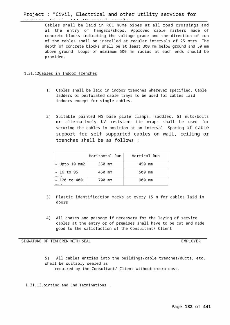
IS 3287 :1965 Industrial light fittings with Plastic reflector
1.35.7.1Reflectors
1) The reflectors shall be made of CRCA sheet steel/ aluminum / silvered glass/chromium plated sheet copper as indicated for the above-mentioned fittings unless otherwise specified.
2) The thickness of steel / aluminum, shall comply with relevant Standards specifed. Reflectors made of steel, shall have stove-enameled/Vitreous-enameled/Epoxy-coating finish.Aluminum used for reflectors, shall be anodized / epoxy stove-enameled/mirror polished. The finish for the reflector shall be indicated above mentioned fitting.
3) Aluminium paint on the reflectors of flameproof fittings is prohibited.
4) Reflectors shall be free from scratches or blisters and shall have a smooth and glossy surface having an optimum light reflecting co-efficient such as to ensure the overall light output specified by the MANUFACTURER.
5) Reflectors shall be readily removable from the housing for cleaning and maintenance without disturbing the lamps and without the use of tools, they shall be securely fixed to the housing by means of positive fastening device of captive type.
1.35.7.2Lamp/Starter Holders
1 Lamp Holders shall comply with relevant Standards. They shall have low contactresistance, shall be resistant to wear and shall be suitable for operation at the specified temperature without deterioration in insulation value. They shall hold the lamps in position under normal condition of shock and vibration met within normal installation and use.
2 Lamp Holder for the fluorescent lamps shall be of the spring loaded bi-pin rotor type. Liveparts of the lamp holder shall not be exposed during insertion or removal of the lamp or after lamp has been taken out. The lamp holder contacts shall provide adequate pressure on the lamp cap pings when in working position.
SIGNATURE OF TENDERER WITH SEAL EMPLOYER
3 Starter holders for fluorescent lamps shall conform to the relevant Standards. All materialused in the construction of the holder shall be suitable for tropical use.
4 The Starter Holder shall be so designed that they are mechanically robust and free fromany operational difficulties. They shall be capable of withstanding the shocks met within normal transit, installation and use.
Project : "Civil, Electrical and other utility services for package -Civil- III (Overhaul complex)VOLUME —II. TECHNICAL SPECIFICATIONS FOR TENDER NO.NK/FW/CAP-ROH-622/2010-11
Page 132 of 441
1.35.7.3Ballasts
1) The ballasts shall be designed, manufactured and supplied in accordance with the relevant Standards. The ballasts shall be designed to have a long service life and low power loss.
2) The electronic ballasts shall be fully enclosed in an aluminum housing shall include a divided wiring compartment to separate the power leads from the control leads. All leads to be color coded.
3) The electronic ballast shall be multi voltage capable and operate from a voltage range of 180 – 305V at 50Hz.
4) Ballasts shall be mounted using self locking, anti-vibration fixings and shall to remove without demounting the fittings. They shall be in dusting combustible enclosures.
5) The ballasts shall be of the inductive, hea1 y duty type, filled with then insulating, moisture repellent polyester compound filled under pressure or Ballasts shall be provided with tapings to set the voltage within specified. End connections and taps shall be brought out in a suitable block, rigidly fixed to the ballast enclosure. The ballast wiring shall bed wire. They shall be free from hum. Ballasts which produce humming be. replaced free of cost by the VENDOR.
6) Separate ballast for each lamp shall be provided in case of multi lamp fittings.
1.35.7.4Lamps
1) The fluorescent lamps shall be "Cool Day Light" type unless otherwise specified and shall be provided with features to avoid blackening of lamp ends. The fluorescent lamps shall have a high lumen output of 3250 lumens. The lamp shall have triple coil electrode with an anode ring and a tri-band Phosphor coating.
2) The lamps shall be capable of withstanding small vibrations and the connections at lead in wires and filaments/electrodes, shall not break under such circumstances.
SIGNATURE OF TENDERER WITH SEAL EMPLOYER
3) Lamps/Tubes shall conform to relevant Standards and shall be suitable for supply voltage and frequency specified.
1.35.7.5Starter
1) Starters shall have bimetal electrodes and high mechanical strength. starters shall bereplaceable without disturbing the reflector or lamps and without the use of any tool.
Project : "Civil, Electrical and other utility services for package -Civil- III (Overhaul complex)VOLUME —II. TECHNICAL SPECIFICATIONS FOR TENDER NO.NK/FW/CAP-ROH-622/2010-11
Page 133 of 441

Starters shall have brass contacts and radio interference capacitor.
2) The starters shall generally conform to the relevant Standards.
1.35.7.6Capacitors
i. The capacitors shall have a constant value of capacitance and shall be connected. acrossthe supply of individual lamp circuits
ii The capacitors shall be suitable for operation at supply voltage and shall have a value ofcapacitance so as to correct the power factor of its corresponding lamp circuit to the extent of 0.95 lag or better.
iii The capacitors shall be hermetically seated preferably in a metal enclosure to preventseepage of impregnant and ingress of moisture.
1.35.7.7Spare Parts
i. Unit prices of the items shall be quoted together with catalogue numbers.
ii. The unit prices shall not however be limited to the above items. The VENDOR may recommend additional spare items and quote the unit prices of the respective items.
1.35.7.8Tests and Test Reports
i. Type tests, acceptance tests and routine tests for the lighting fittings and covered by thisspecification shall be carried out as per the relevant standards for the respective fittings and their accessories.
ii The MANUFACTURER’s type and routine test certificates shall be submitted for testsconducted as per relevant standards for the fittings and accessories. The BIDDER shall submit with his proposal copies of available test certificates of the fittings offered.
SIGNATURE OF TENDERER WITH SEAL EMPLOYER
Project : "Civil, Electrical and other utility services for package -Civil- III (Overhaul complex)VOLUME —II. TECHNICAL SPECIFICATIONS FOR TENDER NO.NK/FW/CAP-ROH-622/2010-11
Page 134 of 441

1.36 SPECIFICATION FOR EARTHING SYSTEM
1.36.1 Scope
The scope under this section covers the following:-
a) Providing Earthing Station.
b) Providing Main Earth Grid
c) Earthing of all panels, DB’s and utilisation equipments.
1.36.2 Codes and Standards
1 The Earthing systems shall comply with all currently applicable standards, regulationsand safety codes of the locality where the installation is to be carried out. Nothing in this specification shall be construed to relieve the contractor of this responsibility.
2 The installation work shall conform to the latest applicable Electricity Rules, RelevantIndian Standards and Codes of Practices as follows :
IS : 3043 -1987 Code of Practice for Earthing (First revision)
IS : 732 -1989 Electrical Wiring Installations
IS : 3975 Galvanized round steel wire
Electricity Rules 32, 61, 67 and 68 of IER 1956
1.36.3 Earthing Electrodes
1) Earthing electrodes shall be designed as per the requirements of IS 3043. The resistance of earth electrodes shall be as low as possible, the maximum allowable value being one Ohm.
SIGNATURE OF TENDERER WITH SEAL EMPLOYER
Project : "Civil, Electrical and other utility services for package -Civil- III (Overhaul complex)VOLUME —II. TECHNICAL SPECIFICATIONS FOR TENDER NO.NK/FW/CAP-ROH-622/2010-11
Page 135 of 441
2) Earth electrodes shall be as far as possible embedded below permanent moisture level. Earth pits shall be further treated with salt and charcoal to improve the soil resistivity. In rocky areas where the required earth resistance cannot be attained using the standard earth electrode. Configuration then application of deep well earth pits should be examined.
1.36.4 Plate Electrode (Copper Plate)
Plate electrodes shall be made of copper plate of 6.3 mm thick and 600 x 600 mm size. The plate shall be buried vertically in ground at a depth of not less than 2.5 mtrs to the top of the plate, the plate being encased in powdered charcoal to a thickness of 15 cm all-round. Salt and river sand shall not be used.
Earth leads to the electrode shall be laid in a medium grade GI pipe and connected to the plate electrode with brass bolts, nuts and washers. The GI pipe of 40 mm dia. shall be placed vertically over the plate and terminated in a funnel of 5 cm above the ground.
The funnel shall be enclosed in masonry precast chamber. The chamber shall be provided with CI frame and CI cover. The earth station shall also be provided with a suitable permanent identification label/tag.
1.36.5 Safe Earthing Electrode (S.E.E)
Safe Earthing Electrode Type-19 shall comprise of a GI pipe with outer dia. of 80 mm and inner dia. of 25 mm or otherwise specified. . The electrode is manufactured from GI pipe with adequate galvanization (i.e., more than 80 – 100 p) to ensure maximum conductivity. The electrode shall not be less than 3.0 Mtrs long buried vertically in a pit of 450 x 450 mm size and filled with back fill compound and connected at the top to a medium grade GI pipe of 19 mm dia or otherwise , clamped to the pipe electrode with brass bolts, nuts and washers.
The top end of the pipe shall be threaded and provided with G.I cap. A hole shall be provided at 100 mm from the top end to receive a 13 mm bolt with double nuts and washers. The funnel and the earth lead connections shall be enclosed in a masonry precast chamber / inspection pit. The chamber shall be provided with C.I frame and C.I cover. A proper permanent identification tag/label/earth cable marker shall be provided for each electrode.
1.36.6 General Requirements:
1) Each installation shall have one common earth grid connected to at least two groups of earth electrodes.
2) The earth grid shall extend throughout the installation in the form of a ring circuit with branch connections to the equipment and structures to be earthed.
Project : "Civil, Electrical and other utility services for package -Civil- III (Overhaul complex)VOLUME —II. TECHNICAL SPECIFICATIONS FOR TENDER NO.NK/FW/CAP-ROH-622/2010-11
Page 136 of 441
1.36.7 Earthing Cables and Connections :
1) Earth systems shall be of solid copper/galvanized flats type, of cross-section specified on the relevant design earth layout drawing.
2) Connections between earth electrodes and main ring earth conductors shall be executed in accordance with Electrical Drawings and in such a way as to facilitate the inspection and testing the earth resistance of each individual earth electrode group without disconnection of the earth system main ring.
3) All un insulated parts of earth conductors shall be suitably protected against direct contact with the soil to prevent electrolytic corrosion. This may be achieved by lap wrapping bared sections with green PVC adhesive tape.
4) All Earthing terminations shall be made with compression type cable lugs. Interconnections shall be directly clamped with compression type branch connectors as detailed in Electrical Drawings.
5) Execution of earth cable branch connection by means of exothermic welding shall require the approval of The Company Site Representative, who will take into account the suitability of the welding equipment and the previous experience of the Contractor’s personnel.
6) The resistance between each earth electrode configuration and the general mass of earth shall not exceed 5 ohms when isolated from the main earth grid.
7) Location of earth electrodes, earth conductor’s connections and earth cable routes shown on the installation earth layout drawing shall be considered as diagrammatic only, and site inspection shall be necessary to determine earth connection onto equipment’s locations and conductor routes prior to installation.
8) Within buildings, strips of high conductivity copper/GI, sized in accordance with the layout Earthing design drawing, should be utilized.
9) Where copper tape or cable is fixed to building structure it shall be by means of purpose made saddles.
11) Fixings shall be made using purpose made lugs and clamps.
12) Fixings requiring drilling of holes through stripes shall be used, considering the effective cross-section of the particular run is within relevant regulations.
Project : "Civil, Electrical and other utility services for package -Civil- III (Overhaul complex)VOLUME —II. TECHNICAL SPECIFICATIONS FOR TENDER NO.NK/FW/CAP-ROH-622/2010-11
Page 137 of 441
13) Where tape or cable is run in the ground or fixed externally, and is liable to corrosion, it shall be wrapped with corrosion-resistant material. Alternatively, PVC wrapped tape or cable may be used.
14) Joints in copper tape shall be tinned before assembly, riveted with a minimum of two rivets, and sweated solid.
15) Where holes are drilled in the earth tape for connection to items of equipment, effective cross-sectional area of connections shall be not less than required to comply with the relevant Regulations.
16)Bolts, nuts and washers for any fixings of earth tape shall be of high-tensile grade.
1.36.8Electrical Equipment
1) Metallic enclosures of all electrical equipment shall be earthed at two ends by connection to the common earth grid.
2) Cross-sectional area of the equipment earth connections shall be in accordance with the earth layout design drawing.
1.36.9 Non-Electrical Equipment
1) All metallic equipment used for storage, processing, transportation or pumping flammable liquids, vapors or gases, and their associated supporting structure or skid, shall be electrically bonded to the installation main earth ring.
2) Electrical bonding of associated metal work, in handrails, walkways, etc., is not necessary if it is demonstrated by testing that they are electrically continuous with the structure. However, the same shall be bonded to earth at one point.
3) Piping which is not in electrical contact with its associated tank or vessel, such as an open discharge line into a tank, shall be bonded to the tank.
4) In installations that do not contain electrical equipment, the resistance between each earth electrode configuration and the general mass of earth shall not exceed 5 ohms when isolated from the main earth grid.
1.36.10 Bonding
Project : "Civil, Electrical and other utility services for package -Civil- III (Overhaul complex)VOLUME —II. TECHNICAL SPECIFICATIONS FOR TENDER NO.NK/FW/CAP-ROH-622/2010-11
Page 138 of 441

1) Metal sheaths and armoured of all cables operating at low voltage, metal conduits, ducting, trucking, and protective conductors associated with such cables, which might otherwise come into contact with adjacent fixed metalwork, shall be effectively either segregated from, or bonded to, adjacent metal work.
2) Metallic sheaths and / or non-magnetic armour of all single-core cables in the same circuit normally shall be bonded together at one and end only have there run (solid bonding) unless specified otherwise.
3) All interior metal, water and gas piping shall be bonded together and made electrically continuous. Non-conductive coatings (such as paint, lacquer and enamel) on equipment to be earthed shall be removed from threads and other contact surfaces to ensure good electrical continuity.
1.36.11 Testing
The following earth resistance values shall be measured with an approved earth meggar and recorded:
1. Each Earthing Stat ion
2. Earthing System as a whole (shall be less than one ohm)
3. Earth Continuity conductors.
1.38 SPECIFICATIONS FOR STREET LIGHT POLES AND POSTS
1.38.1 Scope
This specifications covers the design, material specification, manufacture, testing, inspection, delivery to site and installation & commissioning of Street Light Poles, light fitting and its associated accessories.
1.38.2 Street Light Poles :
1) The street light poles/pathway light poles shall be conforming to IS 1239. The dimensional and other details shall be as specified in the enclosed Standard Drawings.
2) The street light poles shall have M.S pipes of progressively reduced dimensions and post top lanterns poles shall be of uniform cross section. The poles shall be treated with a rigorous rust inhibition process and the outside surface of the pole shall be painted with two coats of paint conforming to IS 2339. Erection of pole as per IS 5613(Part I/Section 2- 1985)
Project : "Civil, Electrical and other utility services for package -Civil- III (Overhaul complex)VOLUME —II. TECHNICAL SPECIFICATIONS FOR TENDER NO.NK/FW/CAP-ROH-622/2010-11
Page 139 of 441
3) Where portion of the pole is required to be embedded in concrete and below ground, the inner circle shall be treated with two coats of bituminous paint.
4) The poles shall be complete with base plate of minimum size 300 x 300 mm and 10 mm thick, and as indicated in the standard drawing.
5) The pole below the ground level shall be grouted in 1:2:4 concrete as per standard drawing. The bottom portion of foundation shall be 800 x 800 mm.
6) Two nos. 50 dia. G.I pipes in arc with 600 mm radius shall be embedded in concrete pedestal upto marshaling box for running of incoming and outgoing cables.
7) Earthing studs shall be provided on pole. The earth wire may be run directly on D-clamp as per IS 5613 (Part I) section 2 –1985
8) Each pole shall be provided with a junction box made of 2 mm thick sheet steel mounted on supporting clamps welded to pole at +450 mm from ground level. The box shall be of weatherproof and dust tight construction with neoprene gaskets and provided with hinged front cover/door with key operated locking device. The box shall have overall dimension of 200 x 150 x 100 mm and shall be complete with the following : Alternatively, arrangement shall be for an integral type junction box as shown in drawing.
i) 8 way 30 Amp strip type terminals each terminal being suitable for termination of loop in and loop out of Aluminium conductor cables upto 25 Sqmm.
ii) 10 Amps SPN (double pole) MCB.
iii) Internal wiring from box to lamp holder of light fitting at top by means of 2 runs of
100 V grade PVC copper conductor wire of size 4 sq mm and one run of 2.5 sq mm
green earth wire.
9) The gate lights installation shall be with 600 mm long MS pipe out of which 300 mm is embedded in compound/gate wall. The junction box shall be flush mounted in wall at +450 mm from ground level and with 19 mm dia. MS conduit interconnecting pole and junction box for running wires. The light poles shall be numbered with neat letters in paint.
10) The rate shall include all items/works described as above and including civil works, reducers suitable size foundation bolts as per standard drawing and any other items not specified but necessary for completion of installation.
1.38.3 Light Fittings:
Project : "Civil, Electrical and other utility services for package -Civil- III (Overhaul complex)VOLUME —II. TECHNICAL SPECIFICATIONS FOR TENDER NO.NK/FW/CAP-ROH-622/2010-11
Page 140 of 441
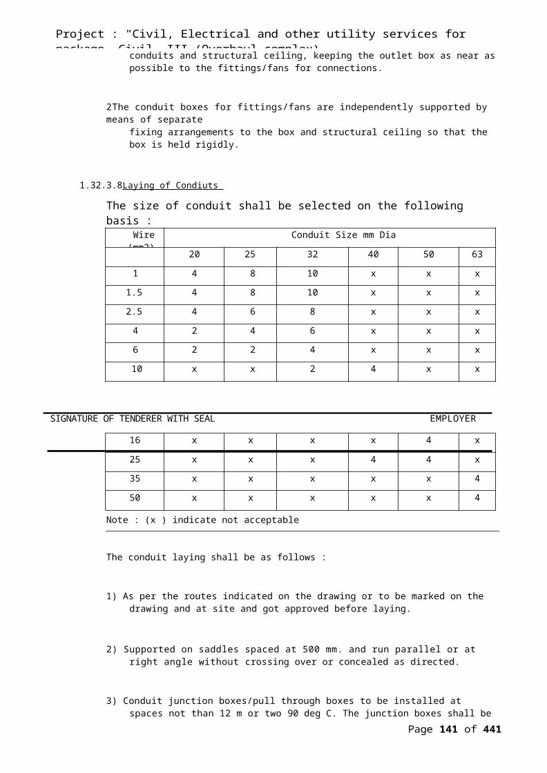
The light fittings shall be of specified type and complete with polyester filled copper choke, HPF condenser holder, ignition, control gear, lamp/bulb of appropriate wattage and type, connectors, fuses etc. whether specified or not in the Bill of Quantities.
NOTE
1) The Contractor shall submit the drawings of the poles based on above specification and schedule for approval from the Consultant/Client before fabrication.
2) The civil foundation works of security and pathway lights have to be executed by the contractor including supply of all materials. The price for erection in schedule of quantities contain the cost of civil foundation.
1.39 TELEPHONE / DATA SYSTEM :
1.39.1 Scope
This includes MS conduit supply and laying , cable supply and laying and termination of Telephone outlets and LAN outlets , jack panel termination and rack fixing, ferruling testing, testing of the telephone and LAN system and submitting the test report to Employer.
1.39.2 Specification for Communication & Data System
1) The conduits for the telephone system as well as Intercom System and Data System shall be same as explained and specified elsewhere for other work. The minimum size of conduits used for Telephone System/Intercom shall be of 25 mm dia.
2) All distribution boxes shall be flush mounting, flat fronted, 16 Gauge sheet steel enclosed boxes flush with wall and properly joined to conduits. The distribution boxes shall incorporate terminal strips of the combined soldering screw type/tag blocks as required.
3) The telephone outlet boxes made of 16 Gauge sheet steel shall be of minimum 75 x 75 x 75 mm. These shall be flush mounting type installed with an approved cover matching with all other outlets in the electrical system and consisting of a CAT 5 RJ 45 outlet and approved by the structured data and communication cabling system.
4) The telephone boxes shall be generally mounted at 450 mm FFL unless otherwise specified/indicated in drawing.
5) The contractor shall consult and co operate with the Consultant/Client when installing the telephone wiring and conduit system and shall abide by their requirements, rules and regulations, shall furnish all work and material to secure their approval of the completed installation.
Project : "Civil, Electrical and other utility services for package -Civil- III (Overhaul complex)VOLUME —II. TECHNICAL SPECIFICATIONS FOR TENDER NO.NK/FW/CAP-ROH-622/2010-11
Page 141 of 441

6) The contractor shall submit detailed drawings showing the telephone terminal and junction boxes fabricated in accordance with above requirements and get approval from the Consultant/Client.
7) Rates shall include a GI fish wire left in the conduit to draw telephone wires. The end of conduit shall be sealed to prevent dirt, dust, mortar or any foreign matter going into telephone conduits.
8) The telephone indoor wires shall be 0.63 mm annealed tinned copper conductor, PVC insulated, twisted into pairs, laid up, taped and overall PVC sheathed, or CAT 5# UTP/STP cable.
9) The telephone outdoor cable shall be 0.63 mm annealed copper conductor, polythene insulated, color coded, twisted into pairs, laid up, jelly filled with petroleum jelly compound, wrapped with non hygroscopic tape under moisture barrier poly al laminated foil tape and embedded with water proof polythene material.
1.39.4 Backbone wiring
The function of backbone wir ing shall be to provide interconnection between telecommunication closets in riser and equipment room in the telecommunication wiring system. The backbone wiring shall consist of the transmission media, intermediate and main patch panel on each floor and mechanical terminations for interconnections of telecommunication closet sand equipment rooms.
The backbone wiring shall use star technology wherein each telecommunication close shall be wired to a main cross connect / patch panel or an intermediate patch panel at then to a main patch panel, as case may be. There shall be no more than two hierarchical levels of cross connects I patch panel in the backbone wiring. For data system, where riser distance is more that 90 M, fiber optic backbone shall be used.
Care shall be taken to ensure that cross talk coupling between individual twisted p shall not affect the transmission performance of multipair cables.
1.39.5 Horizontal Wiring
Project : "Civil, Electrical and other utility services for package -Civil- III (Overhaul complex)VOLUME —II. TECHNICAL SPECIFICATIONS FOR TENDER NO.NK/FW/CAP-ROH-622/2010-11
Page 142 of 441

The horizontal wiring shall be the portion of the telecommunication wiring system extends from the work area telecommunication outlets to the telecommunication closet. The horizontal wiring shall include the telecommunication outlet in the work area, the mechanical terminations for horizontal cables and cross connections located in telecommunication closet.
The horizontal wiring shall be of star technology with each work area telecommunication outlet connected to a telecommunication closet. The horizontal wiring shall be CAT copper conductor PVC wire drawn in MS conduit, generally run above false ceiling of floor separated from the electrical wiring in an appropriate manner so as to eliminate electromagnetic interference. Maximum distance of wire from mechanical termination the media in closet to outlet shall be limited to 90 meters.
RJ-45 patch panel shall be provided in the closet. All wires/cables shall be identified tags and schedule identifying each termination shall be submitted to the Client after completion of installation.
1.40 SPECIFICATION FOR LAN & WORK.
1.40.1 Code and Standards:
TIA/EIA-568-B.1 Commercial Building Telecommunications Cabling StandardPart 1: General Requirements
TIA/EIA-568-B.2 Commercial Building Telecommunications Cabling StandardPart 2: Balanced Twisted Pair Cabling Components.
TIA/EIA-568-B.2-1 Transmission Performance Specif icat ions for 4-pair1000Augmented Category 6 Cabling
TIA/EIA-606-A Administration Standard for the TelecommunicationsInfrastructure of Commercial Buildings
TIA/EIA-942 Telecommunications Infrastructure Standard for DataCenters
1.40.2 General Requirments
1) The number of points of connectivity in each floor/wing as well as the exact distribution of the same in the faculty rooms/laboratories/conference rooms etc to be given sheet.
2) The number of points of connectivity in each floor/wing as well as the exact distribution of the same in the faculty rooms/laboratories/conference rooms etc to be given sheet.
Page 143 of 441

3) The horizontal cabling will be 4 core unshielded twisted pair (utp) category 6 (Gigabit to the desktop) terminated with information outlets of either single or dual or quad depending on the requirement at the specific location.
4) Patch panels / jack panels should be provided along with the patch cords of adequate lengths conforming to the standards.
5) Cabling activity, for both copper and fiber optic includes all the associated material and related civil work as a total turn key solution. for example, cable pulling, connection of cables, crimping of cables, up to termination of nodes and the associated labour for fixing racks and panels etc
6) The work related to the connectivity requirements in the main communication rooms as well as the floor level/wing level communication rooms will be within the scope.
7) After the cable plant is implemented completely, it has to be tested using appropriate tools to ensure that it meets all the stated requirements and the test reports have to be submitted.
1.40.3 Testing
After the cable plant is implemented completely, it has to be tested using appropriate tools to ensure that it meets all the stated requirements and the test reports have to be submitted to the Employer.
1.41 SPECIFICATION FOR PUBLIC ADDRESS SYSTEM
1.41.1 Scope of Work
The scope of work shall include designing supplying and installing of Public Address System. The work under this system shall consist of furnishing all materials, equipment’s and appliances and labour necessary to install the said system, complete with Speakers, Amplifiers, Mike, Zone selection Panel for interfacing with other systems.
The PA System is designed to serve the dual purpose of making general announcement or to transmit the fire tone under fire condition.
1.41.2 System Design
Page 144 of 441

The Speakers shall be distributed in the entire floor and shall be configured in different zones. The announcement can be made in zone wise or to all the speakers simultaneously in ALL CALL mode. Fire Alarm shall be announced immediately on receipt of Fire signal from the panel to all zones.
1.42.3 Amplifiers
1) All amplifiers shall be mixing type for combining speech and music.
2) The power amplifiers shall have adequate continuous (RMS) power output to meet the requirement of the configuration. The unit shall be capable of delivering the rated output watts with less than 0.05% harmonic distortion in the design band width. The amplifier shall have a broad band frequency response of 20 Hz to 20 KHz. The output voltage and impedance shall meet with the system requirements. Amplifiers shall be protected against over loads and output shorts and a special thermal overload on the heat sink.
3) The distributed audio amplifiers shall be magnetically coupled switch mode type with two input signal sources selectable manually or automatically by the fire alarm system. The amplifier shall incorporate a push-to-talk switch. Output wattage and volts shall be as shown in the schedule of work or as required to meet the needs of the PA System.
4) Power as well as audio amplifiers shall be mounted in suitable wall mounted / floor standing enclosures.
1.41.4 Speakers
1) Speakers shall be especially designed for broadcasting high quality, integrated emergency fire alarm signals and voice communications and approved by an appropriate authority for use in such situations.
2) Speakers shall be ceiling or wall mounted as shown in the schedule of work and shall be completed with mounting brackets accessories etc. Speakers shall be in wooden or metal enclosures.
3) Speakers shall be of high efficiency yielding maximum output at minimum power across 200 – 12000 Hz frequency range. Speakers shall have a line matching transformer for direct connection to amplifiers with multiple taps. Speakers shall be mounted in a rugged metal housing with vandal resistant grille.
4) Speakers external appearance shall be approved by the Architects.
5) Speakers shall be interconnected in the zone configuration.
Page 145 of 441

1.41.5 Zone Selection Panel
1) The user interface to the entire public address system shall be the Zone Selection Panel. It shall be able to address 10 zones.
2) The Panel shall have one Microphone for announcements. The selection of announcement is done through the Panel. The announcement/Fire tone can be made zone wise. The Control Panel shall have individual zone selection switches as well as ALL CALL switch.
1.41.6 Wiring
1) PA system wiring shall be done by 2 core x 1.5 sq. mm PVC insulated copper cable.
2) The speakers in each zone are connected in parallel and are connected to the respective output. The cables from each zone are separately routed and terminated in the Panel.
1.41.7 Testing and commissioning
Entire PA System shall be tested to establish the following.
i. Functionality of the P A System
ii Combined systems shall be tested for the overriding feature for prioritising fire alarm and life safety requirements.
iii Acceptable audibility of the public address in all spaces and record sound pressure levels of the Public address vis a vis the ambient noise levels.
1.42 TECHNICAL SPECIFICATION FOR LIGHTINING ARRESTOR
1.42.1 Code and Standards
IS : 2309 -1989 Code of practice for protection of buildings and allied structuresagainst lighting(Second revision)
SIGNATURE OF TENDERER WITH SEAL EMPLOYER
Page 146 of 441

1.42.2 Design
i. Optimal Protection against the direct effects of lightning.
ii. Improved maximum effectiveness and longevity.
i i i . Total autonomy.
iv. Activates itself only when there is a risk of lightning
v. Permanent single drop from the tip of the Air- terminal down to the earth.
i. Full compliance with international standards - example the French Standard NF C17-102
ii. Reliability and Sturdiness to be tested by both International test laboratories and in Real- live lightning conditions, tested and witnessed by reputable authorities (for example, Atomic Energy Commission)
iii. Proven, Robust Design able to withstand Multiple Lightning Strikes.
iv. 5 Model Range offering customized solutions for each Project.
1.42.3 Scope
This specification covers the requirements of supply, installation, testing and commissioning of lightning protection system in conformity with the requirements of IS:2309, consisting of vertical air termination the horizontal air termination’s, down conductors and earth stations.
1.42.4 Air Termination’s.
The air terminations shall be provided at the points shown on the drawings. The vertical air termination’s shall consist of copper spikes fixed onto 25 mm dia. copper tubes of at least 1.5 mtrs long grouted to the surface of the roof with base plate as approved by Consultants.
The horizontal air terminations shall consist of a rigid network of tapes fixed to the surface of the roof. All exposed metal work and roof structures forming part of the structure to be protected shall be bonded to the net work by the conductors of the appropriate cross section.
1.42.5 Down Conductors
Page 147 of 441

Air terminations shall be connected to the earth terminations by tapes fixed onto walls of the structures with spacers. The tapes shall be securely fixed to walls by means of brass saddles and metallic fasteners. Where the down conductors are laid underground, they shall be laid at a depth of 750 mm below the ground level, buried in trench, covered with a 100 mm thick layer of sand and protected by cable protection tiles.
All metallic parts of the building above the main roof level including ducts, towers , pipes gutters and other mechanical equipment’s shall be bonded to the down conductors.
1.42.6 General
1 The materials shall be free from rust, scale and other electrical and mechanical defects.The size, materials and quantity shall be as specified.
2 Steel earthing conductors above ground shall be hot dip galvanized. If painted it shall begiven two coats of approved bit mastic paint/anti corrosive paint.
3 Test links in suitable enclosures shall be installed by the contractor at no extra cost forconnection between each lightning conductor down conductor and earth electrode.
4 The scope of installation of lightning conductors on the roof of buildings shall includelaying, anchoring, fastening and cleating of horizontal conductors, grouting of vertical rods where necessary, laying, fastening/cleating/welding of the down comers on the walls/columns of the building and connection to the test links above ground level, and up to earth station.
5 Lightning protection conductors shall not be connected to other general earthingconductors.
6 The lightning protection air termination rods and/or horizontal air termination conductorsshall be fixed in such a way that they remain in their installed position even during adverse weather conditions.
7 The down conductors shall follow a direct path to earth. There shall not be any sharp,turns and kinks in the down conductors.
8 All joints in the down conductors shall be of welded/brazed type. All metallic structureswithin 2 m vicinity of down conductors shall be bonded to the lightning protection system.
9 Every down conductor shall be provided with a test link at about 1000 mm above groundlevel. The test link shall be directly connected to the earthing system/electrode.
Page 148 of 441

10 The lightning protection system shall not be in direct contact with the underground metallic service ducts, cables, cable conduits and metal enclosures of electrical equipment’s.
11 Lightning conductors shall not pass through or run inside G.I conduits.
12 Wherever required, if indicated in drawings, for fuel oil and other inflammable liquid storage tanks lightning and protection shall be provided with horizontal conductors strung between tall poles covering the entire areas.
1.45.7 Joints Bonding
The system shall have preferably no joints and they shall be made mechanically and electrically strong and effective. Bolted joints should only be used on test points or on bonds to as existing metal. Generally jointing/connections/installations shall be as in earthing system.
1.45.8 Earth Terminations
Suitable number of earth terminations shall be provided. The earth termination shall consist of pipe/plate earth electrode as specified elsewhere in the Earthing Specification, and generally conforming to IS : 3043. The earth terminations shall be complete in all respects with chamber and cover, etc. as per the detailed specifications.
Before installing the lightning protection system, the contractor shall obtain approval from the Engineer with respect to the locations of air termination’s and the routes for the down conductors.
1.45.9 Test Clamps/Links
Test clamps/links shall be manufactured from phosphor bronze or approved equivalent with four fixing holes. Tape conductors shall be fixed to flat roof surfaces by means of suitable fixing arrangement as approved.
All fixing screws shall be brass.
1.45.10 Testing.
Page 149 of 441

Suitable testing links be provided at required points as per the code of practice CP 326/IS 2309. The contractor shall carry out tests on completion of the installation and submit the readings for approval.
APPROVED MAKE OF MATERIAL
Sr. No. Materials Manufacturer/Supplier
1) HT Cable Termination Kit Raychem
2) HT Cable Fort Gloster / CCI / Torrent/ Finloex/ Asian
3) LT Power, Control and Signal Cables Finolex/ Polycab / Torrent/ CCI/ Fort Gloster/Asian
4) ACB Siemens/ Crompton/Schneider
5) MCCB Siemens/ L&T/Merlin Gerin
6) MCB Legrand/Siemens/Hager
7) Capacitors (APP/Gas filled) ABB / EPCOS / Siemens
8) UV / OV/ ELR Minilec / Prok Devices / AVR Electronics
9) Cable Glands – Double Compression Type
Dowell /Comet /HMI
1) Cable Lugs Dowell / Multi / Uma
2) Switch Disconnector Fuse Unit Siemens / L&T
3) Load Break Change over SFU / Isolator Siemens / L&T
4) HRC Fuses / Fuse Base Siemens./English Electric/ L & T
5) Earth Leakage Relay/CBCT Prok-DVS
6) PF Relay EPCOS / ABB / L & T
7) Protective Relays L&T / Alsthom / Easun / Siemens
8) Selector Switches Kaycee / L&T / Salzer
9) Meter – Ammeter and Volmteter (Analog Type)
AE/Meco/Rishab
10) Indicating Lamps / Push Buttons: Technik / Vaishno / ABB / Schneider / Siemens
11) CT’S – Resin Cast Voltamp / Kappa / Kalpa
12) Contactors / Overload Relays/MPCB’ Siemens/ L&T
Page 150 of 441
13) Indicating True RMS Meter(DIGITAL TYPE)
Conzerv / HPL Socmac / Rishab
SIGNATURE OF TENDERER WITH SEAL EMPLOYER
23) Industrial Power Socket Outlets (Metal Clad)
Crompton/ MDS /Cuttler Hammer
24) MCB Distribution Boards Legrand / L&T-Hager
25) Domestic Switches & Sockets / Fan Regulators (MODULAR TYPE) Sample to be approved
MK/Anchor –Roma/Crabtree
26) Telephone & LAN Sockets D-Link/Tyco
27) Light Fittings(Industrial / Commercial Philps /Bajaj/Crompton
28) Ceiling Fans 5 star rated Usha / Bajaj / Havells
29) Exhaust Fan Crompton/Almonard
30) Wall Mounted Fans Almonard/Crompton
31) FRLS Wire Finolex / Polycab
32) FRLS PVC Conduits & Accessories(Heavy duty only)
VIP /National / Nelco
33) MS Conduits & Accessories GI Bharat / Supreme/Javeri /BEC/BIS approved
34) Perforated & Ladder type Cable Trays Elcon / Profab / Patni
35) Raceways / PVC Trunking Schnedier / Honeywell / Legrand
36) Batteries SMF Type Exide
37) Battery Charger Universal / Abhay Electric/AMARARAJA
38) Telephone Connector Ternimal Box KRONE.
39) Telephone Cables Jelly filled Armored Paired Cables
Delton / Finolex/Polycab/Havell
40) Telephone cabling system TATA Telecom/ Siemens/ Lucent /D-Link /Adonix/Molex
41) LAN Data cabling system Tyco
42) RJ45 Patch Panel Tyco
43) Communication Rack APW - Presidemt
44) Street Light Pole Baja/Metal Coats(K-LITE)
Page 151 of 441

45) PA System Philips/Ahuja
46) Safe Earth Electrode Aslok Safe Electrode Type T-39Z
47) Flameproof /Increased Safety Switchgear & lighting fixtures
Flameproof Equipments P Ltd/ Sudhir Switchgear/CEAG/Baliga
48) Steel TATA/Vizag/Jindal
General
SIGNATURE OF TENDERER WITH SEAL EMPLOYER
1) Detail submittals in the form of catalogues specification sheets, and samples were called for, shall be submitted one week from the date of order and approvals shall be obtained on the type of accepted make before procurement are made.
2) Out of the approved makes of materials mentioned above, the make of materials to be used on the work shall be as decided by the Consultant/Client jointly.
3) In respect of materials for which approved makes are not specified above, the material makes to be decided by the Consultant/Client jointly and as per sample approved before procurement.
4) Equipments approved and supplied shall have local servicing facilities available in the region.
5) In case of non availability of the first indicated makes, the contractor shall opt for the other makes after getting approval from the Consultant/Client jointly. If the difference of amount is on the lower side, the same shall be passed on to the Clients.
Page 152 of 441