waveform and numerology to support 5g services and ... · pdf file1 waveform and numerology to...
TRANSCRIPT

1
Waveform and Numerology to Support 5G Servicesand Requirements
Ali A. Zaidi, Robert Baldemair, Hugo Tullberg, Håkan Björkegren, Lars Sundström, Jonas Medbo,Caner Kilinc and Icaro Da Silva
Ericsson Research, Sweden
Abstract—The standardization of the next generation 5G radioaccess technology has just started in 3GPP with the ambitionofmaking it commercially available by 2020. There are a numberof features that are unique for 5G radio access compared to theprevious generations such as a wide range of carrier frequenciesand deployment options, diverse use cases with very different userrequirements, small sized base stations, self-backhaul, massiveMIMO, and large channel bandwidths. In this paper, we proposea flexible physical layer for the New Radio access technology(NR) to meet the 5G requirements. A symmetric physical layerdesign with OFDM is proposed for all link types includinguplink, downlink, device-to-device, and backhaul. A scalableOFDM waveform is proposed to handle the wide range of carrierfrequencies and deployments.
I. INTRODUCTION
The standardization of the next generation radio technologyhas started in 3GPP (3rd Generation Partnership Project) thisyear (2016) with the ambition of making 5G wireless systemscommercially available around 2020. There are three mainchallenges that need to be addressed by 5G Radio AccessTechnology to enable a truly networked society: i) a massivegrowth in the number of connected devices, ii) a massivegrowth in traffic volume, and iii) an increasingly wide rangeof applications with varying requirements and characteristics.Broadly, we can classify 5G use cases (or services) in thefollowing groups:
• Enhanced Mobile Broadband (eMBB), requiring veryhigh data rates and large bandwidths;
• Ultra Reliable Low Latency Communications (URLLC)requiring very low latency, very high reliability andavailability;
• Massive Machine Type Communications (mMTC), re-quiring low bandwidth, high connection density, enhancedcoverage, and low energy consumption at the user end.
The requirements for the above mentioned 5G servicesare diverse and have implications for new spectrum anddeployments. New spectrum for 5G is expected to be availableby 2020. The actual frequency bands and the amount ofspectrum, have not been identified yet. All bands, from below1 GHz up to 100 GHz are potential candidates for 5G [1]. 5Gservices will require a range of different bandwidths. At thelow end of the scale, support for massive machine connectivitywith relatively low bandwidths is envisioned. In contrast,verywide bandwidths may be needed for high capacity scenarios,e.g., 4K video and future media. Millimeter wave spectrum
Figure 1: Radio Access Vision for 2020 and beyond: 5G RadioAccess comprises of LTE Evolution and a New Radio AccessTechnology (NR) that is not backwards compatible with LTEand is operable from sub-1 GHz to 100 GHz.
bands (i.e., near and above 30 GHz) will play a role in somedeployments to reach the envisioned capacity [2].
3GPP aims to develop and standardize components for anew Radio Access Technology (RAT) which is envisioned tooperate in frequencies up to 100 GHz to serve the diverse usecases. The new radio access technology is referred to as NRthroughout this paper, which is currently the accepted acronymin 3GPP [3]. NR is intended to be optimized for performancewithout considering backward compatibility in the sense thatlegacy LTE UEs do not need to be able to camp on an NRcarrier. LTE is also expected to evolve to capture a part of the5G requirements. The vision of 5G wireless access is shown inFig. 1, where NR and LTE Evolution are integral parts of 5G.LTE evolution is expected to operate below 6 GHz frequenciesand NR is envisioned to operate from sub-1 GHz up to 100GHz. A tight integration of NR and LTE is envisioned, inorder to efficiently aggregate NR and LTE traffic.
Designing physical layer of NR will be the first step towardsits development. This paper provides principles for the designof waveform and numerology1. The paper is organized asfollows. In Section II, we highlight key design requirementsfor NR. Based on the design requirements, we propose wave-form and numerology in Sections III–V. Finally, Section VI
1Numerology refers to waveform parametrization, e.g., cyclic prefix, sub-carrier spacing in OFDM.
2
concludes the paper.
II. PHY DESIGN REQUIREMENTS FORNR
In the following, we list important features of NR that haveimplications on new waveform and numerology.
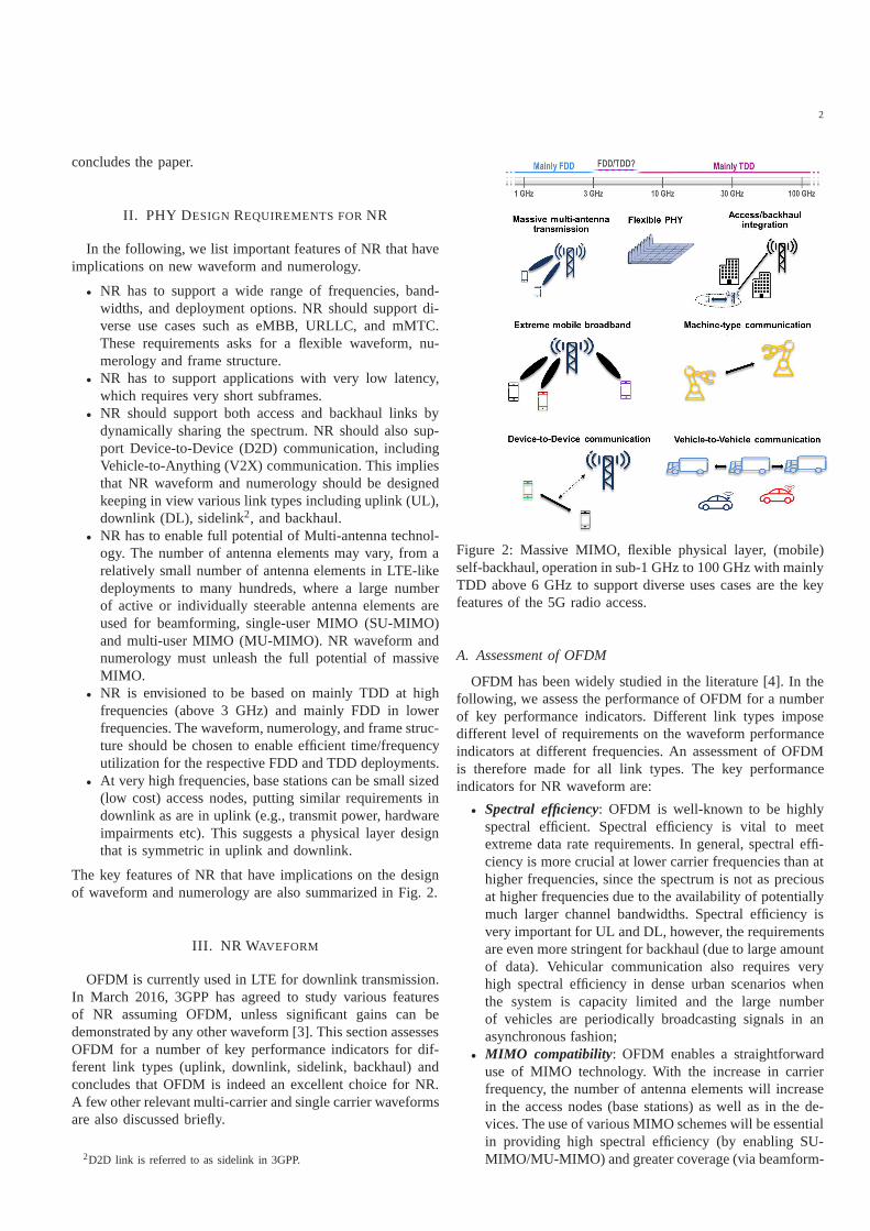
• NR has to support a wide range of frequencies, band-widths, and deployment options. NR should support di-verse use cases such as eMBB, URLLC, and mMTC.These requirements asks for a flexible waveform, nu-merology and frame structure.
• NR has to support applications with very low latency,which requires very short subframes.
• NR should support both access and backhaul links bydynamically sharing the spectrum. NR should also sup-port Device-to-Device (D2D) communication, includingVehicle-to-Anything (V2X) communication. This impliesthat NR waveform and numerology should be designedkeeping in view various link types including uplink (UL),downlink (DL), sidelink2, and backhaul.
• NR has to enable full potential of Multi-antenna technol-ogy. The number of antenna elements may vary, from arelatively small number of antenna elements in LTE-likedeployments to many hundreds, where a large numberof active or individually steerable antenna elements areused for beamforming, single-user MIMO (SU-MIMO)and multi-user MIMO (MU-MIMO). NR waveform andnumerology must unleash the full potential of massiveMIMO.
• NR is envisioned to be based on mainly TDD at highfrequencies (above 3 GHz) and mainly FDD in lowerfrequencies. The waveform, numerology, and frame struc-ture should be chosen to enable efficient time/frequencyutilization for the respective FDD and TDD deployments.
• At very high frequencies, base stations can be small sized(low cost) access nodes, putting similar requirements indownlink as are in uplink (e.g., transmit power, hardwareimpairments etc). This suggests a physical layer designthat is symmetric in uplink and downlink.
The key features of NR that have implications on the designof waveform and numerology are also summarized in Fig. 2.
III. NR WAVEFORM
OFDM is currently used in LTE for downlink transmission.In March 2016, 3GPP has agreed to study various featuresof NR assuming OFDM, unless significant gains can bedemonstrated by any other waveform [3]. This section assessesOFDM for a number of key performance indicators for dif-ferent link types (uplink, downlink, sidelink, backhaul) andconcludes that OFDM is indeed an excellent choice for NR.A few other relevant multi-carrier and single carrier waveformsare also discussed briefly.
2D2D link is referred to as sidelink in 3GPP.
Figure 2: Massive MIMO, flexible physical layer, (mobile)self-backhaul, operation in sub-1 GHz to 100 GHz with mainlyTDD above 6 GHz to support diverse uses cases are the keyfeatures of the 5G radio access.
A. Assessment of OFDM
OFDM has been widely studied in the literature [4]. In thefollowing, we assess the performance of OFDM for a numberof key performance indicators. Different link types imposedifferent level of requirements on the waveform performanceindicators at different frequencies. An assessment of OFDMis therefore made for all link types. The key performanceindicators for NR waveform are:
• Spectral efficiency: OFDM is well-known to be highlyspectral efficient. Spectral efficiency is vital to meetextreme data rate requirements. In general, spectral effi-ciency is more crucial at lower carrier frequencies than athigher frequencies, since the spectrum is not as preciousat higher frequencies due to the availability of potentiallymuch larger channel bandwidths. Spectral efficiency isvery important for UL and DL, however, the requirementsare even more stringent for backhaul (due to large amountof data). Vehicular communication also requires veryhigh spectral efficiency in dense urban scenarios whenthe system is capacity limited and the large numberof vehicles are periodically broadcasting signals in anasynchronous fashion;
• MIMO compatibility: OFDM enables a straightforwarduse of MIMO technology. With the increase in carrierfrequency, the number of antenna elements will increasein the access nodes (base stations) as well as in the de-vices. The use of various MIMO schemes will be essentialin providing high spectral efficiency (by enabling SU-MIMO/MU-MIMO) and greater coverage (via beamform-

3
ing). Beamforming will be instrumental in overcominghigh propagation losses at very high frequencies (cover-age limited scenarios);
• Peak-to-Average-Power-Ratio (PAPR): OFDM has highPAPR (like other multi-carrier waveforms). A low PAPRis essential for power efficient transmissions from thedevices (e.g., UL, sidelink). Low PAPR becomes evenmore important at very high frequencies. It is noteworthythat small sized low cost base stations are envisioned athigh frequencies, therefore, low PAPR is also importantfor DL. High PAPR in OFDM can also be substan-tially reduced via various well-known PAPR reductiontechniques with only minor compromise in performance[5]. For NR, OFDM with PAPR reduction (without DFTprecoding3) is an attractive option for uplink and sidelink.The use of one waveform for all link types will also maketransceiver designs and implementations symmetric forall transmissions. Moreover, it is important to note thatthe requirements on PAPR for uplink and downlink willbecome more similar in the future due to low cost smallsized base stations.;
• Robustness to channel time-selectivity: is vital in highspeed scenarios. High speed scenarios are relevant inlarge cell deployments. The large cell deployments arenot expected at very high frequencies due to harsh prop-agation conditions (coverage limitation). At very highfrequencies, the deployments are expected in the formof small cells where mobility is not a major concern.However, V2X services may be enabled at very highfrequencies, making robustness to channel time selectivityvery important performance indicator at very high fre-quencies. Traditionally backhaul link is fixed and mobilityis not a concern, however for the envisioned mobilebackhaul (e.g., access nodes on vehicles), robustness tochannel time selectivity will become relevant. OFDM canbe made robust to channel time-selectivity by a properchoice of sub-carrier spacing;
• Robustness to channel frequency-selectivity: Channelfrequency-selectivity is always relevant to the transmis-sion of large bandwidth signals over wireless channels.Channel frequency selectivity depends on various factorssuch as type of deployment, beamforming technique, andsignal bandwidth. OFDM is robust to frequency selectivechannels;
• Robustness against phase noise: An OFDM system canbe made robust to phase noise by a proper choice ofsub-carrier spacing. Phase noise robustness is crucial forall link types where a device (transmitter/receiver) isinvolved. In particular, low-phase noise oscillators maytoo expensive and power consuming for devices. Phasenoise robustness is also important for future low costbase stations. Basically, any link that involves a device
3LTE uses DFT-Spread OFDM (DFTS-OFDM) for both UL and sidelinklink due to its lower PAPR than OFDM. However, DFTS-OFDM has certaindrawbacks compared to OFDM such as lesser flexibility for scheduling (incase of SC-FDMA) and more complex MIMO receiver with degraded linklevel and system level performance [6]. Since MIMO will alsobe a keycomponent for UL and sidelink in NR, DFTS-OFDM is not a preferred option.
and/or low cost base station puts a high requirementon phase noise robustness of waveform, especially ifthe communication takes place at high frequencies sincephase noise increases with carrier frequency;
• Transceiver baseband complexity: The baseband com-plexity of an OFDM receiver is lowest among all candi-date waveforms that have been studied in the past for 5GRAT [7]. Baseband complexity is always very importantfor the devices, especially from the receiver perspective.For NR, complexity is even a major consideration forbase stations, since a base station can be small sizedaccess node (especially at high frequencies) with limitedprocessing capability. At very high frequencies and largebandwidths, the receiver may also have to cope withsevere RF impairments;
• Time localization: OFDM is very well-localized in timedomain, which is important to efficiently enable (dy-namic) TDD and support latency critical applicationssuch as URLLC. Dynamic TDD is envisioned at highfrequencies and provision of low latency is essential forall link types, especially backhaul and V2X links mayimpose very high requirement;
• Frequency localization: OFDM is less localized in fre-quency domain. Frequency localization can be relevantto support co-existence of different services potentiallyenabled by mixing different waveform numerologies infrequency domain on the same carrier. Frequency local-ization is also relevant if asynchronous access is allowedin UL and sidelink. In general, frequency localization ofa waveform may not be important at high frequencieswhere large amount of channel bandwidth is available;
• Robustness to synchronization errors: The provisionof cyclic-prefix in OFDM makes it robust to timingsynchronization errors. Robustness to synchronizationerrors is relevant when synchronization is hard to achievesuch as sidelink. It can also be relevant if asynchronoustransmissions are allowed in the uplink4;
• Flexibility and scalability: OFDM is a flexible wave-form, that can support diverse services in wide range offrequencies by proper choice of subcarrier spacing andcyclic prefix. Further discussion on OFDM numerologydesign that fulfills a wide range of requirements is givenin Sec. IV.
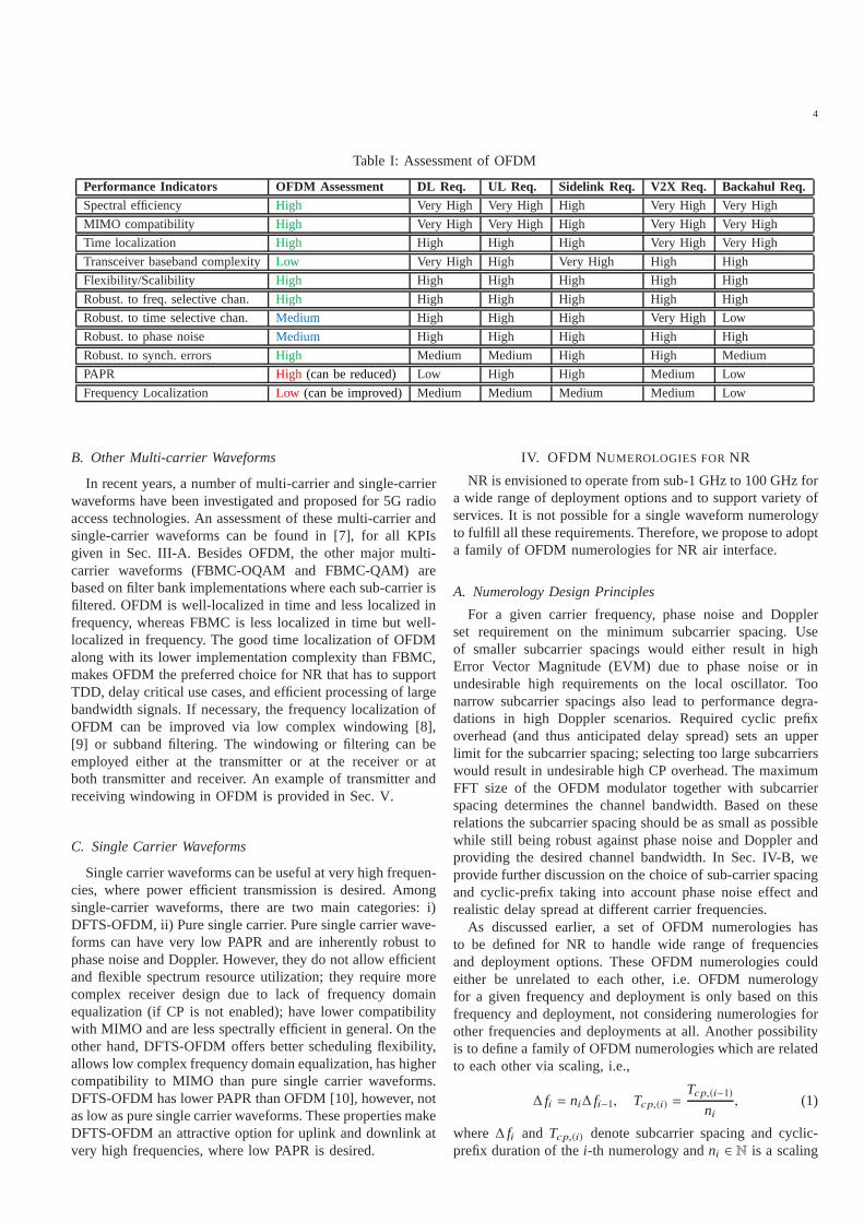
In Table I, we provide a summary of OFDM assessment.An OFDM assessment “High” in second column means thatOFDM has good performance in general for the given KPI,whereas a link requirement “High” for a KPI tells thatthe given waveform KPI is important for the given linktype in general. We assess D2D and V2X cases separatelydue to different levels of requirements. For example, V2Xcommunication has higher requirements on mobility, systemcapacity, whereas lower requirements on power efficiencywhen compared with UE-to-UE communication. Based on theassessment in Table I, we conclude that OFDM is an excellentchoice for NR air interface.
4We note that LTE only supports synchronous uplink transmission (exceptfor PRACH), which is realized via timing advance at the UEs.
4
Table I: Assessment of OFDM
Performance Indicators OFDM Assessment DL Req. UL Req. Sidelink Req. V2X Req. Backahul Req.Spectral efficiency High Very High Very High High Very High Very High
MIMO compatibility High Very High Very High High Very High Very High
Time localization High High High High Very High Very High
Transceiver baseband complexityLow Very High High Very High High High
Flexibility/Scalibility High High High High High High
Robust. to freq. selective chan. High High High High High High
Robust. to time selective chan. Medium High High High Very High Low
Robust. to phase noise Medium High High High High High
Robust. to synch. errors High Medium Medium High High Medium
PAPR High (can be reduced) Low High High Medium Low
Frequency Localization Low (can be improved) Medium Medium Medium Medium Low
B. Other Multi-carrier Waveforms
In recent years, a number of multi-carrier and single-carrierwaveforms have been investigated and proposed for 5G radioaccess technologies. An assessment of these multi-carrierandsingle-carrier waveforms can be found in [7], for all KPIsgiven in Sec. III-A. Besides OFDM, the other major multi-carrier waveforms (FBMC-OQAM and FBMC-QAM) arebased on filter bank implementations where each sub-carrierisfiltered. OFDM is well-localized in time and less localized infrequency, whereas FBMC is less localized in time but well-localized in frequency. The good time localization of OFDMalong with its lower implementation complexity than FBMC,makes OFDM the preferred choice for NR that has to supportTDD, delay critical use cases, and efficient processing of largebandwidth signals. If necessary, the frequency localization ofOFDM can be improved via low complex windowing [8],[9] or subband filtering. The windowing or filtering can beemployed either at the transmitter or at the receiver or atboth transmitter and receiver. An example of transmitter andreceiving windowing in OFDM is provided in Sec. V.
C. Single Carrier Waveforms
Single carrier waveforms can be useful at very high frequen-cies, where power efficient transmission is desired. Amongsingle-carrier waveforms, there are two main categories: i)DFTS-OFDM, ii) Pure single carrier. Pure single carrier wave-forms can have very low PAPR and are inherently robust tophase noise and Doppler. However, they do not allow efficientand flexible spectrum resource utilization; they require morecomplex receiver design due to lack of frequency domainequalization (if CP is not enabled); have lower compatibilitywith MIMO and are less spectrally efficient in general. On theother hand, DFTS-OFDM offers better scheduling flexibility,allows low complex frequency domain equalization, has highercompatibility to MIMO than pure single carrier waveforms.DFTS-OFDM has lower PAPR than OFDM [10], however, notas low as pure single carrier waveforms. These properties makeDFTS-OFDM an attractive option for uplink and downlink atvery high frequencies, where low PAPR is desired.
IV. OFDM NUMEROLOGIES FORNR
NR is envisioned to operate from sub-1 GHz to 100 GHz fora wide range of deployment options and to support variety ofservices. It is not possible for a single waveform numerologyto fulfill all these requirements. Therefore, we propose to adopta family of OFDM numerologies for NR air interface.
A. Numerology Design Principles
For a given carrier frequency, phase noise and Dopplerset requirement on the minimum subcarrier spacing. Useof smaller subcarrier spacings would either result in highError Vector Magnitude (EVM) due to phase noise or inundesirable high requirements on the local oscillator. Toonarrow subcarrier spacings also lead to performance degra-dations in high Doppler scenarios. Required cyclic prefixoverhead (and thus anticipated delay spread) sets an upperlimit for the subcarrier spacing; selecting too large subcarrierswould result in undesirable high CP overhead. The maximumFFT size of the OFDM modulator together with subcarrierspacing determines the channel bandwidth. Based on theserelations the subcarrier spacing should be as small as possiblewhile still being robust against phase noise and Doppler andproviding the desired channel bandwidth. In Sec. IV-B, weprovide further discussion on the choice of sub-carrier spacingand cyclic-prefix taking into account phase noise effect andrealistic delay spread at different carrier frequencies.
As discussed earlier, a set of OFDM numerologies hasto be defined for NR to handle wide range of frequenciesand deployment options. These OFDM numerologies couldeither be unrelated to each other, i.e. OFDM numerologyfor a given frequency and deployment is only based on thisfrequency and deployment, not considering numerologies forother frequencies and deployments at all. Another possibilityis to define a family of OFDM numerologies which are relatedto each other via scaling, i.e.,
∆ fi = ni∆ fi−1, Tcp,(i) =Tcp,(i−1)
ni, (1)
where∆ fi and Tcp,(i) denote subcarrier spacing and cyclic-prefix duration of thei-th numerology andni ∈ N is a scaling

5
factor. The duration of OFDM symbol is inverse of subcarrierspacing. With this scaling approach, sampling clock rates ofdifferent OFDM numerologies relate to each other via thescaling factors{ni}, which simplifies the implementation. Wetherefore propose to adopt this scaling approach, i.e., OFDMnumerologies are derived from a base OFDM numerologyvia the scaling. In principle, the scaling factors{ni} can beselected independently of each other, however, it is desirablethat the scaling factors follow certain relationship (given in(2)) which will be discussed in the following.
We propose that the number of OFDM symbols per sub-frame should be equal for all numerologies, meaning thatthe subframe duration would shrink with the increase in sub-carrier spacing. Maintaining equal number of OFDM symbolsper subframe for all numerologies simplifies scheduling andreference signal design. Furthermore, this would enable shorterlatencies for wider subcarrier numerologies (to be used inhigh frequency small cell deployments where some of theURLLC applications are envisioned). If equal number ofOFDM symbols are assumed for all numerologies, then thefollowing relationship holds for subframe durations betweendifferent numerologies:
Ts f ,(i) =Ts f ,(i−1)
ni=
Ts f ,(i−2)
nini−1
= · · · =Ts f ,(1)∏i
k=1 nk.
For adjacent TDD networks that are using different OFDMnumerologies, it is desirable that an integer number of sub-frames from one OFDM numerology fits into one subframe ofthe other OFDM numerology to enable time aligned downlinkand uplink periods. If the sub-frame durations of differentnumerologies do not fulfill the above condition, then twoneighbouring TDD networks would require guard time in theframe structure to enable synchronous operation, which willnot be an efficient resource utilization. Therefore, we proposethat the scaling factors are chosen such that a subcarrierspacing is integer divisible by all smaller subcarrier spacing,i.e.,
∆ fi = 2L(i)∆ f1, ∀i ∈ {1, 2, ...,M}, (2)
whereL(i) ∈ Z, M is the number of OFDM numerologies, and∆ f1 is sub-carrier spacing of the base numerology. This impliesthat the scaling factor in (1) should be chosen asni = 2L,whereL is an integer.
B. Impact of Phase Noise and Channel Delay Spread
Phase noise in an OFDM system causes two main effects:i) Common Phase Error (CPE), ii) Inter Carrier Interference(ICI) [11]. CPE refers to phase rotation of all sub-carriersbyan equal amount and can be corrected easily with the use ofpilot subcarriers. ICI is an additive noise (not always Gaussian)and usually hard to compensate for depending on how fastthe phase variations are. In the following, we evaluate theeffect of ICI in OFDM as a function of sub-carrier spacing atdifferent oscillator frequencies. First, we will briefly describethe phase noise model used in the evaluations and then presentthe evaluation results.
The local oscillator (LO) consists of a crystal oscillator(XO) and a voltage-controlled oscillator (VCO) connected in
102 103 104 105 106 107 108
Offset Frequency (Hz)
-160
-140
-120
-100
-80
-60
-40
-20
0
PS
D (
dBc/
Hz)
fLO = 20 GHz
fLO = 40 GHz
fLO = 60 GHz
fLO = 80 GHz
(a) Phase noise power spectral densities at different oscillator frequen-cies.
104 105 106 107
Subcarrier Spacing (Hz)
20
25
30
35
40
45
50A
chie
vabl
e S
IR (
dB)
fLO = 20 GHz
fLO = 40 GHz
fLO = 60 GHz
fLO = 80 GHz
(b) Achievable SIR subject to phase noise (due to inter-carrier-interference) at different oscillator frequencies.
Transmitter-to-Receiver Distance (m)
0 20 40 60 80 100 120 140
RM
S D
elay
Spr
ead
(ns)
0
50
100
150
200
250
30058.8 GHz14.8 GHz2.44 GHz
(c) Channel delay spread has a weak dependency on carrier frequency.
Figure 3: Phase noise impact and channel delay spread atdifferent frequencies.

6
Table II: Proposed OFDM Numerologies
OFDM paramteres Up to 6 GHz Up to 20 GHz Up to 40 GHz Above 40 GHzSubcarrier spacing 15 kHz 30 kHz 60 kHz 2L× 60 kHzClock frequency 61.44 MHz 122.88 MHz 245.76 MHz 2L× 245.76 MHz
Samples per OFDM symbol 4096 4096 4096 4096OFDM symbol duration 66.77µs 33.33µs 16.67µs 16.67/2L
µsCP samples 288 288 288 288CP duration 4.69 µs 2.35 µs 1.17 µs 1.17/2L
µs
a Phase-Locked Loop (PLL). At low offset frequencies, theLO phase noise is dominated by the XO phase noise, shiftedup by 20 log( fLO/ fXO). At high offset frequencies, the LOphase noise is dominated by the -20dB/dec of the VCO. Inthe following evaluations, the considered LO design is basedon XO running at 490 MHz and VCO with Figure-of-Mertit5
(FOM) = -190 dB and a power consumption of 30mW. Withthis design, the Power Spectral Density (PSD) of the phasenoise is given in Fig. 3a. The Signal-to-Interference Ratio(SIR) due to ICI for a subcarrier can be computed according tothe expression in Sec. 5.2 in [11]. In Fig. 3b, we have evaluatedSIR of the middle subcarrier (suffering from highest ICI) asa function of subcarrier spacing for four different oscillatorfrequencies. According to Fig. 3b, 40 dB SNR can be achievedwith ∆ f = 30 kHz at 20 GHz oscillator frequency,∆ f = 60
kHz at 40 GHz oscillator frequency,∆ f = 500 kHz at 60 GHzoscillator frequency.
For a fixed CP overhead in an OFDM symbol, larger subcar-rier spacing implies smaller CP. Cyclic-prefix has to be greaterthan the delay spread of the channel. Therefore, channel delayspread sets an upper limit on the subcarrier spacing. Somerecent channel measurements at different carrier frequencies(2.44 GHz, 14.8 GHz, and 58.8 GHz) in a street micro cellscenario have shown that delay spread is similar at differentfrequencies assuming omni-directional antennas, see Fig.3c[13]. Similar conclusions are made in a recent white paper[14], which shows that delay spread has a weak dependencyon frequency. Furthermore, it has been observed that delayspread is much lower in LOS conditions compared to theNLOS conditions. According to Fig. 3c, the max. value ofRMS delay spread is 0.2µs, which is important to keep inmind while setting the upper limit on subcarrier spacing. Itis also important to note that the observed delay spread ofthe channel depends on few other factors such as deploymentscenario and beam forming. Delay spread is usually smallerin indoor environments and use of narrow beams may reducedelay spread as well.
C. Proposed Numerologies
We now propose a set of OFDM numerologies following thedesign principles discussed in Sec. IV-A and the importantobservations made in Sec. IV-B related to impact of phasenoise and channel delay spread at different carrier frequencies.We choose LTE numerology as the base numerology, i.e.,
5FOM has been defined according to (1) in [12].
∆ f1 = 15 kHz, Tof dm,(1) = 66.67 µs, andTcp,(1) = 4.69 µs.The other numerologies are derived from the base numerologyaccording to (2) and (1). The derived numerologies are givenin Table II. We note that in LTE, CP duration of the firstOFDM symbol in a slot is 5.2µs. We propose the same forNR base numerology (which is LTE numerology), althoughnot explicitly mentioned in Table II. Moreover, LTE providesan option for extended CP which should also exist in NR.As proposed in Table II, different numerologies are suitablefor different frequency ranges considering the achievableSNRsubject to phase noise and channel delay spread discussedin Sec. IV-B. According to Fig. 3c, CP duration must begreater than 0.2µs which implies L = 3 in the last columnof Table II, meaning that the largest subcarrier spacing shouldbe 480 kHz if the numerologies are derived according to (2)6. We recall that in presence of ICI (due to phase noise), 480kHz subcarrier spacing can achieve approx. 40 dB SNR at 60GHz oscillator frequency and approx. 35 dB SNR at 80 GHzoscillator frequency (cf. Fig. 3b).
There are a few important reasons for proposing LTEnumerology as the base numerology, that are listed below:
• 3GPP has specified LTE numerology for Narrow-BandInternet-of-Things (NB-IOT). NB-IOT devices are de-signed to operate for 10 years and more on a singlebattery charge. Once such an NB-IOT device is deployedit is likely that within the device life time the embeddingcarrier gets reframed to NR.
• NR deployments can happen in the same band as LTE.With adjacent carrier LTE TDD, NR must adopt thesame UL/DL switching pattern as LTE TDD does. Everynumerology where (an integer multiple of) a subframe is1 ms can be aligned with regular subframes in LTE. InLTE, duplex switching happens in special subframe. Tomatch the transmission direction in special subframes, thesame numerology as in LTE is needed.
• LTE Release-8 was standardized after a thorough nu-merology study, therefore, it is reasonable to aim for simi-lar numerology at LTE-like frequencies and deployments.
D. Frame Structure
In LTE, one radio frame comprises of 10 subframes andeach sub-frame consists of two slots with seven OFDMsymbols per slot. The notions of slot may not be necessary,
6In practice, maximum delay spread is typically four to five times greaterthan RMS delay spread and CP should be chosen accordingly.

7
therefore, we only define subframe for NR. The proposedsubframe consists ofNsymb OFDM symbols, but not allsymbols in a subframe are always used for active transmission.We define two basic subframe types, one for UL and onefor DL. Transmission in a DL subframe always starts at thebeginning of the subframe and can extend from 0 up to atmostNmax OFDM symbols. Transmission in an UL subframealways stops at the end of the subframe and can extend from0 up to at mostNmax OFDM symbols. The gaps between DLand UL transmission, if present, are used as guard in TDD fortransmission in the reverse direction within a subframe.
The duration of a single subframe has to be very short.Depending on the numerology, a sub-frame duration can betens of micro seconds to a few hundred micro seconds. Forthe OFDM numerologies given in Table II, we propose sevenOFDM symbols per subframe, i.e.,Nmax = 7. This impliessub-frame duration of 500µs for 15 kHz numerology, 250µsfor 30 kHz numerology, 125µs for 60 kHz numerology, andreaching down to 15.62µs for 480 kHz subcarrier spacing.Very short subframes are important for URLLC applicationsrequiring low latency and such devices will typically checkfor control signaling transmitted at the beginning of everyDLsubframe. Given the latency critical nature, the transmissionitself can also be very short, e.g., a single subframe. For eMBBdevices, extremely short subframes are typically not needed.Therefore, one can aggregate multiple subframes and schedulethe subframe aggregate using a single control channel.
V. M IXING NUMEROLOGIES
For some use-cases, mixing of different numerologies onthe same carrier frequency may be beneficial, e.g., to supportdifferent services with very different latency requirements.In an OFDM system with different numerologies (subcar-rier bandwidth and/or cyclic prefix length) multiplexed infrequency-domain, only subcarriers within a numerology areorthogonal to each other. Subcarriers of one numerologyinterfere with subcarriers of another numerology, since energyleaks outside the subcarrier bandwidth and is picked up bysubcarriers of the other numerology. The inter-numerologyinterference is illustrated in Fig. 4a, where a numerology basedon subcarrier spacing∆ f1 interferes with another numerologybased on subcarrier spacing∆ f2, even though there is a smallguard band between the two transmissions.
The inter-numerology interference can be reduced by eitherapplying time-domain filtering per numerology (sub-band)or time-domain windowing. In the following, we considerwindowing approach due to its low complex implementationand superior performance [9].
A. Transmitter Windowing
The main reason for the slow decay of OFDM spectrumis signal discontinuities at OFDM symbol boundaries. Withtransmitter windowing, the boundaries of each OFDM symbolare multiplied with a smooth slope in time-domain, increasingsmoothly from 0 to 1 (increasing slope) or 1 to 0 (decreasingslope), see Fig. 4b. The increasing slope is applied at thebeginning of the cyclic prefix while the decreasing slope is
applied after the end of the core OFDM symbol within an extraadded cyclic suffix. Fig. 4b also shows that the increasing slopeof the next OFDM symbol overlaps with the decreasing slopeof the previous OFDM symbol. Since the receiver keeps onlythe samples of the core OFDM symbol, transmitter windowingis transparent to the receiver.
(a) Inter-numerology interference.
(b) An illustration of transmitter windowing.
(c) An illustration of receiver windowing.
(d) Windowing reduces inter-numerology interference.
Figure 4: Transmitter and/or receiver windowing is an attrac-tive option if different OFDM numerologies are mixed on thesame carrier.

8
B. Receiver Windowing
A standard OFDM receiver cuts out the desired OFDMsymbol period by applying a rectangular window in time-domain to the received signal and subsequently applies anFFT. Application of a rectangular window in time-domaincorresponds to convolution in frequency-domain with a sinc-like function. The sinc-like function leads to high interferencepick-up from adjacent non-orthogonal signals such as OFDMsignals with other numerologies. To reduce interference pick-up, the rectangular window must be replaced by a smoothwindow function. To this end, a smooth increasing windowslope is applied at the boundary between cyclic prefix and coreOFDM symbol (half within cyclic prefix and half within coreOFDM symbol); a decreasing smooth window slope is appliedat the boundary between core OFDM symbol and added cyclicsuffix, see Fig. 4c. If the applied window slopes fulfil theNyquist criteria (i.e. they are centre asymmetric) the signalpart cut away by the decreasing windowing slope (indicatedby the upper-right orange triangle in Fig. 4c) is the same asthe remaining signal part after application of the increasingwindow slope within the cyclic prefix (indicated by the lower-left orange triangle in Fig. 4c since the cyclic prefix is a copyof the last part of OFDM symbol. If the windowed cyclicprefix part (lower-left orange triangular in Fig. 4c) is addedto the last part of the core OFDM symbol the core OFDMsymbol is restored at its second boundary. The core OFDMsymbol can also be restored at the first symbol boundaryby applying the same trick. Now the complete OFDM isrestored and subcarriers are orthogonal again. The FFT isapplied to the restored core OFDM symbol as indicated inFig. 4c. Interference pick-up remains reduced as long as theinterference does not have a periodicity equal to the OFDMsymbol duration.
In Fig. 4d, we show the effect of transmitter and receiverwindowing on inter-numerology interference assuming 15kHz and 30 kHz numerologies (cf. Table II) multiplexedin frequency domain. It can be observed that windowingsubstantially increases the achievable Signal-to-InterferenceRatio (SIR). (SIR is averaged across subcarriers within oneresource block which is assumed 12 subcarriers.) Windowinghas extremely low complexity. Only the windowed samplesare scaled and overlap-and-add over the windowed periods isperformed.
VI. CONCLUSIONS
We proposed a symmetric physical layer for all link types(e.g., UL, DL, sidelink, backhaul link) based on OFDM withscalable numerology. OFDM was assessed for a number ofperformance indicators, link types, and frequency ranges.Weobserved that OFDM is an excellent choice for all link types inNR, due to its high time localization, low complex transceiverdesign, high spectral efficiency and easy integration withMIMO technologies. The main drawback of OFDM (like allmulti-carrier waveforms) is its high PAPR, which can be alimitation at very high frequencies. There exist well-knownmethods to reduce PAPR of OFDM with minor degradation inperformance. OFDM with PAPR reduction can be particulary
useful for UL and sidelink. For very high frequencies, DFTS-OFDM may also be an interesting waveform due to its lowPAPR and frequency domain equalization. However furtherinvestigations are necessary to conclude if DFT precoding isnecessary at very high frequencies.
We proposed a family of OFDM numerologies consider-ing implementation complexity, phase noise robustness andrealistic channel delay spreads at different carrier frequencies.The proposed family of numerologies consists of a basenumerology and the remaining numerologies in the family arederived by scaling up the subcarrier spacing and scaling downthe cyclic-prefix of the base numerology by the same factor.The scaling approach is simple implementation wise. Enablingdifferent numerologies merely requires scaling of the sam-pling clock frequency without changing any other waveform(OFDM) parameter. Furthermore, the preferred option for thenumerology scaling factor is2L times the base numerology,whereL is an integer. Such scaling is important to allow twoneighbouring TDD networks to enable two different numerolo-gies without any resource waste (i.e., without using guardtime). The preferred choice for the base numerology is LTEnumerology due to various reasons. The most important reasonis co-existence with NB-IOT, for which 3GPP has alreadyspecified LTE numerology. Finally, we showed that if differentnumerologies are multiplexed on the same carrier, then the lowcomplex (transmitter/receiver) windowing of OFDM can beuseful to significantly suppress inter-numerology interference.
ACKNOWLEDGMENT
The research leading to these results received fundingfrom the European Commission H2020 programme undergrant agreements n671650 (5G PPP mmMAGIC project) andn671680 (5G PPP METIS-II project).
REFERENCES
[1] S. Methley, W. Webb, S. Walker, and J. Parker, “5G candidate bandstudy: Study on the suitability of potential candidate frequency bandsabove 6 GHz for future 5G mobile broadband systems,” QuotientAssociates Limited, Tech. Rep., March 2015.
[2] J. Luo, A. A. Zaidi, J. Vihriala, and et. al, “Millimeter-wave air-interfacefor 5G: Challenges and design principles,” inETSI Workshop on FutureRadio Technologies – Air Interfaces, 2016, pp. 1–6.
[3] RP-160671, “Study on NR new radio access technology,”3GPP TSGRAN Meeting 71, March 2016.
[4] T. Hwang, C. Yang, G. Wu, S. Li, and G. Y. Li, “OFDM and its wirelessapplications: A survey,”IEEE Transactions on Vehicular Technology,vol. 58, no. 4, pp. 1673–1694, May 2009.
[5] D.-W. Lim, S.-J. Heo, and J.-S. No, “An overview of peak-to-averagepower ratio reduction,”Journal of Communications and Networks,vol. 11, no. 3, pp. 229–239, June 2009.
[6] J. Zhang, C. Huang, G. Liu, and P. Zhang, “Comparison of the linklevel performance between ofdma and sc-fdma,” inCommunications andNetworking in China (ChinaCom), Oct. 2006, pp. 1–6.
[7] A. A. Zaidi, J. Luo, R. Gerzaguet, and et. al., “A preliminary studyon waveform candidates for 5G mobile radio communications above 6GHz,” in IEEE Vehicular Technology Conference (VTC Spring), May2016.
[8] S. H. Muller-Weinfurtner, “Optimum nyquist windowing in OFDMreceivers,”IEEE Transactions on Communications, vol. 49, no. 3, pp.417–420, Mar 2001.
[9] E. Bala, J. Li, and R. Yang, “Shaping spectral leakage: A novel low-complexity transceiver architecture for cognitive radio,” IEEE VehicularTechnology Magazine, vol. 8, no. 3, pp. 38–46, Sept. 2013.

9
[10] G. Huang, A. Nix, and S. Armour, “Impact of radio resource allocationand pulse shaping on PAPR of SC-FDMA signals,” inProc. IEEE18th International Symposium on Personal, Indoor and Mobile RadioCommunications (PIMRC), Sept 2007, pp. 1–5.
[11] J. Stott, “The effects of phase noise in COFDM,”EBU Technical Review,1998.
[12] L. Fanori and P. Andreani, “Highly efficient Class-C CMOS VCOs,including a comparison with Class-B VCOs,”IEEE Journal of Solid-State Circuits, vol. 48, no. 7, pp. 1730–1740, July 2013.
[13] R1-160846, “Street microcell channel measurements at2.44, 14.8 &58.68 GHz,”3GPP TSG-RAN WG1 No. 84, Feb. 2016.
[14] 5GCM White Paper, “5G channel model for bands up to 100 GHz,”http://www.5gworkshops.com, Dec. 2015.