wave optics module - kesco | 計測エンジニアリングシ · pdf file ·...
TRANSCRIPT

Wave Optics Module

• Electromagnetic wave simulations at optical frequencies (wavelengths from nm to µm).
• Optical components are often much larger than the wavelength:– Semiconductor laser (5 x 5 x 500 µm3)– Directional coupler (mm length)
What is Wave Optics?

Electromagnetics in COMSOL Multiphysics is extended by add-on Modules
1) Start Here
2) Add Modules based upon your needs
3) Additional Modules extendthe physics you can address
4) Interface with your CAD data and MATLAB

Types of Electromagnetics Modeling
RF Module
Static Low Frequency Transient High Frequency
0
tE tsinE tE tsinE
Electric and magnetic fields do not vary in time.
Fields vary sinusoidally in time, but there is negligible radiation.
Fields vary arbitrarily in time, radiation may or may not be significant. Objects can be moving.
Fields vary sinusoidally in time, energy transfer is via radiation.
Wave Optics Module

Comparison to RF Module
• RF Module is very flexible for simulations of domains not much larger than the wavelength (f = 1 GHz λ = 30 cm)
• Maximum mesh element size, hmax, must be a fraction of the wavelength, hmax = λ/6.
• Consider semiconductor laser example:– Volume is 5 x 5 x 500 = 12 500 µm3.– Material wavelength is 1.55/3.5 = 0.44 µm => hmax = 73 nm.– Number of elements is 12 500/0.0733 = 31 000 000!– Requires approximately 25 GB RAM only to do the meshing!

Comparison to Ray Optics
• Ray (Geometrical) Optics is suitable for simulations on structures much much larger than the wavelength.
• Rays can efficiently be traced through complex geometric domains and materials.
• Approximate method - wavelength is zero– Diffractive effects are not considered.
• Electromagnetic heating is difficult with Ray Optics.

Wave Optics Applications
• Integrated optics– Waveguides and couplers
• Fiber optics– Photonic crystal fibers– Fiber Bragg gratings
• Nonlinear optics– Harmonic generation– Sum- and difference-frequency mixing
• Optical scattering– Surface scattering– Scattering from nanoparticles
• Lasers and amplifiers– Semiconductor lasers– Rod, slab and disk laser design

Multiphysics Applications
• Laser heating– Materials processing– Electromagnetics, heat transfer, structural mechanics
• Semiconductor optoelectronics– Device design– Electromagnetics and semiconductor physics
• Optical lithography– How to transfer the perfect aerial image into the resist– Electromagnetics, chemical reactions, heat transfer
• Optical sensors– When your nice device is sensitive to the environment, you have a sensor– Electromagnetics, structural mechanics, heat transfer, ...

Wave Optics Module User Interfaces
• Electromagnetic Waves, Beam Envelopes• Electromagnetic Waves, Frequency Domain• Electromagnetic Waves, Transient• Electromagnetic Waves, Time Explicit• Models created with the RF Module before version 4.3b can be
opened with the corresponding version 4.3b Wave Optics interfaces

Electromagnetic Waves, Beam Envelopes
Electric field envelope, E1(x)Electric field, E(x)
x
E(x) = E1(x)exp(‐jk1x)

Electromagnetic Waves, Beam Envelopes
Electric field envelope, E1(x)Electric field, E(x)
x
E(x) = E1(x)exp(‐jk1x)|dE1/dx|<< |k1E1|
* * * * *

Mathematically speaking
• Insert exp ·• in Helmholtz equation
(1)• and solve for from
(2)• Notice that
– Eq. (2) is NOT an approximation of Eq. (1).– Eq. (2) is still a kind of wave equation.

Comparison with the Beam Progagation Method (BPM)• BPM also solves for the electric field envelope.• However, BPM uses the Slowly Varying Envelope Approximation
(SVEA) and removes the second derivatives in the propagation direction.
• BPM provides an approximative solution to Helmholtz equation.• Beam Envelopes Method of the Wave Optics Module comes with
*no* approximation– Limitation is instead that you need to know the direction of propagation to fully utilize it—you often do in
Optics

Propagation settings
• Unidirectional– exp ·– One main propagation direction– In Model Library
• Directional coupler• Self-focusing
• Bidirectional (default settings)– exp · exp ·– Use for models with reflective surfaces
• Fabry-Perot cavities
• Beam-splitter

User-defined phase function
Phase
Field norm

Coupling of Bidirectional Waves
• Bidirectional waves are only automatically coupled at boundaries– For domain coupling, for instance for fiber Bragg gratings with periodic refractive
index distribution, add explicit weak expressions

When NOT to use the Beam Envelopes interface
• To use the Beam Envelopes interface, you need to be able to guess good wave vectors
• If your problem is NOT characterized by one or two main wave vectors
– DON’T use the Beam Envelopes interface• Use the Electromagnetic Waves, Frequency Domain interface instead
– Example is scattering• One incoming wave, but scattered wave propagates in many directions

Formulations per Module
COMSOL Multiphysics1 AC/DC Module RF Module
Static Electric CurrentsStatic Joule HeatingElectrostaticsMagnetic Fields2
Electric Currents in SolidsElectric Currents in ShellsJoule HeatingElectrostaticsMagnetic FieldsInduction HeatingMagnetic and Electric FieldsRotating MachineryElectric Circuits
Electromagnetic Waves- Frequency Domain- Time Explicit- Transient
Microwave HeatingTransmission Line EquationsElectrical Circuits
1) Core package contains a reduced set of boundary conditions for these formulations 2) 2D and 2D-axisymmetric geometries and static and low frequency formulations only
Wave Optics Module
Electromagnetic Waves- Frequency Domain- Time Explicit- Transient- Beam Envelopes
Laser Heating
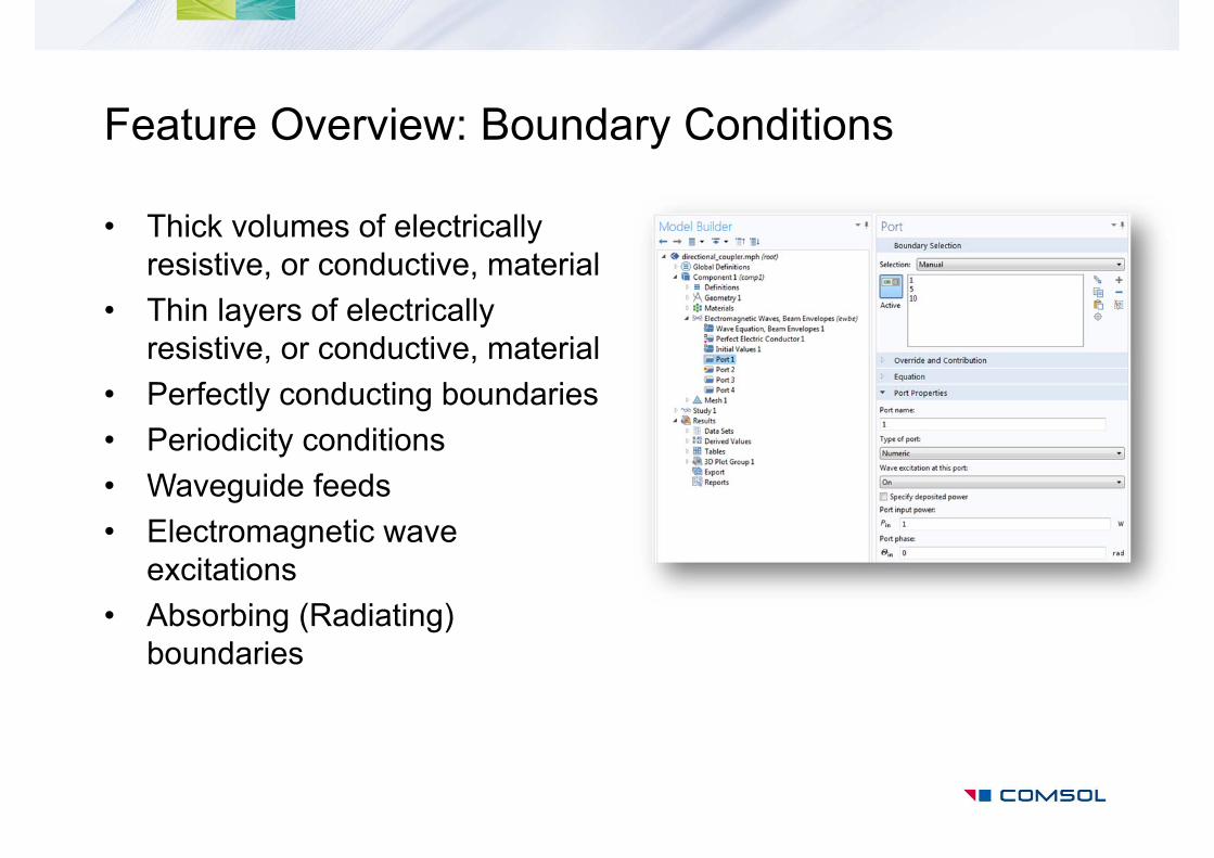
Feature Overview: Boundary Conditions
• Thick volumes of electrically resistive, or conductive, material
• Thin layers of electrically resistive, or conductive, material
• Perfectly conducting boundaries• Periodicity conditions• Waveguide feeds• Electromagnetic wave
excitations• Absorbing (Radiating)
boundaries

Material Models
rr
r
DEDPED
ED
0
0
0
rr
r
BHBMHB
HB
0
00
0
EJ
• All material properties can be:– Constant or nonlinearly dependent upon the fields– Isotropic, Diagonal, or Fully Anisotropic– Defined via Rule-of-Mixtures models– Bi-directionally coupled to any other physics, e.g. Temperature, Strain– Fully User-Definable
• Wave Optics Module supports loss tangents and dispersion models– Drude-Lorentz, Sellmeier, and Debye dispersion

Data Extraction
Far‐Field Radiation Pattern
2221
1211
SSSS
Lumped Parameters Touchstone file export
• S-parameters, Impedance, and Admittance• Touchstone file export• Far-field plots for radiation

Additional Modules for ElectromagneticsPlasma Module1 MEMS Module2 Particle Tracing Module3
Tunable Cavity FilterMicrowave Plasma Multipactor
Solves DC Discharge, Capacitively Coupled Plasmas, Inductively Coupled Plasmas, and Microwave Plasmas.
Couples structural mechanics and electrostatics for the modeling of electroactuation, as well as piezoelectric devices.
Computes paths of charged particles through electric and magnetic fields as well as fluid fields.
1) Depending upon the type of plasma being modeled, the AC/DC or the RF Module may also be needed2) Contains the same 3D electrostatic, electric currents in solids, and electric circuits capabilities as the AC/DC Module3) Does not require any other Modules

Additional Modules for Electromagnetics (cont’d)Semiconductor Module1
MOSFET
Solves for the electric potential and electron and hole concentrations in semiconductor materials.
1) Does not require any other Modules

The Optimization Module
• Gradient-Free optimization allows for optimization of geometric parameters, and allows for remeshing of the geometry.
- Nelder-Mead, Coordinate Search, and Monte Carlo algorithms.- Optimize one or more geometric dimensions for a CAD model created directly in COMSOL
Multiphysics or via the LiveLink™ products
• Gradient-Based optimization requires more user interaction to set up a differentiable objective function and a moving mesh, but can handle many more design variables, and can solve much faster.
- Adjoint method is used to compute exact sensitivities
Bowtie Antenna Optimization

Example Models, Wave Optics Module

Directional Coupler
http://www.comsol.com/showroom/gallery/14593/
• A directional coupler formed by two embedded optical waveguides in close proximity• GaAs cladding, and ion-implanted GaAs core material• Excitation: the two first supermodes of the waveguide structure - the symmetric and
antisymmetric modes• Demonstration of coupling from one of the waveguides to the other waveguide
Electric field from an exaggerated aspect ratio view

Mach Zehnder Modulator
• Mach Zehnder optical modulator used for electrically controlling the output amplitude of the light wave passing through the device.
• Waveguide-based modulators are used for communication to reduce the device size and the driving voltage.
http://www.comsol.com/showroom/gallery/15061/

Resonant Structures
• COMSOL can find the resonant frequency and Quality factor of an closed and open cavity structures by solving the eigenvalue problem:
• Typical examples:– Optical Resonators
jjk rr 0EE 0
20
1

Modeling of a Fabry-Perot Cavity
• A Fabry-Perot cavity is a slab of dielectric in air• The simplest optical resonator• Objective is to find resonant frequency and Q-factor• Frequency-Domain and Eigenvalue solutions are shown
http://www.comsol.com/showroom/gallery/14711/

Scattering
• An background electromagnetic field of known shape, such as a plane wave, interacts with various materials and structures. The objective is to find the total field and scattered fields by solving:
• Typical example:– Mie Scattering
scatteredbackgroundtotal
totalrtotalr jkEEE
0EE
0
20
1

Optical Scattering off of a Gold Sphere
• A gold sphere is illuminated by light of wavelength 400-700nm• Symmetry reduces the problem size• Second order elements represent the sphere shape to high accuracy• A Perfectly Matched Layer (PML) truncates the modeling domain• Gold is modeled as having negative and complex valued permittivity• Far-field calculation computes the scattered fields• Losses within the sphere are computed
http://www.comsol.com/showroom/gallery/14697/
Gold sphere

User-defined Electric Displacement Example
• COMSOL can generate harmonics via a transient wave simulation, using nonlinear material properties:
rr
rrr tttDED
0DAAA
0
0001
Remanent electric displacement

Second Harmonic Generation
http://www.comsol.com/showroom/gallery/14701/
• Gaussian beam passing through an optically nonlinear medium• Polarization dependents upon the electric field magnitude• Requires transient non-linear modeling • Frequency doubling is observed
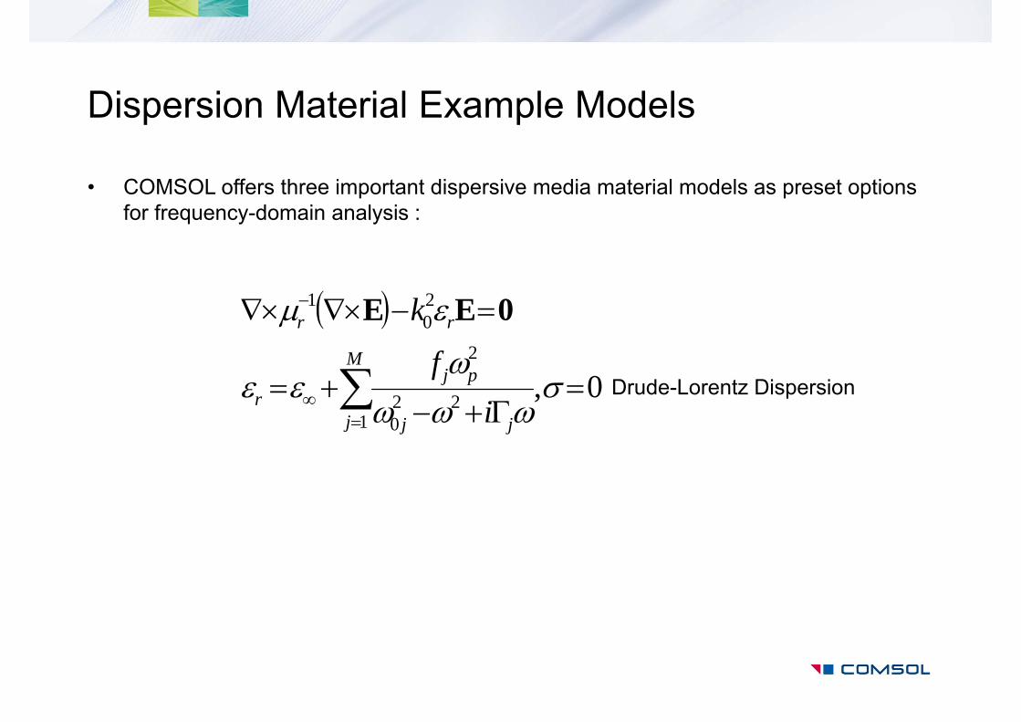
Dispersion Material Example Models
• COMSOL offers three important dispersive media material models as preset options for frequency-domain analysis :
0,1
220
2
20
1
M
j jj
pjr
rr
if
k 0EE
Drude-Lorentz Dispersion

• A Gaussian electromagnetic wave is incident on a dense array of very thin wires (or rods).
• The rod array behaves as if it was a continuous metal sheet for light polarized along the rods, whereas for light polarized perpendicular to the rods, the array is almost transparent to the electromagnetic wave.
Nanorods
http://www.comsol.com/showroom/gallery/12665/
Polarization perpendicular to the rods
Polarization along the rods
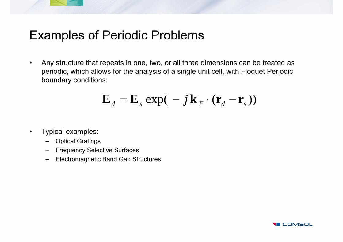
Examples of Periodic Problems
• Any structure that repeats in one, two, or all three dimensions can be treated as periodic, which allows for the analysis of a single unit cell, with Floquet Periodic boundary conditions:
• Typical examples:– Optical Gratings– Frequency Selective Surfaces– Electromagnetic Band Gap Structures
))(exp( sdFsd j rrkEE

• A 2D array of silver cylinders patterned on a substrate is modeled with one unit cell using Floquet periodicity
• Higher-order diffraction is captured
The 2D model can be easily expanded to 3D using periodic port.
Plasmonic Wire Grating
http://www.comsol.com/showroom/gallery/14705/

• An array of high refractive index posts has a photonic band gap• Removing one row of posts can create a waveguide• Over certain frequency ranges, good guiding is observed
Photonic Crystal Waveguide Bend
http://www.comsol.com/showroom/gallery/14703/

• Optical fibers are the backbone of the telecommunications infrastructure• This introductory model computes the effective index of several modes• A straight fiber, a single step-index waveguide made of silica glass• A bent fiber, the bend makes the modes lossy
Step Index Fiber Bend
SiO2 (doped)
SiO2
445711 .n
437812 .n http://www.comsol.com/showroom/gallery/14707/
Straight fiber model Bent fiber model

• Structural stresses can result in a change in refractive index• Plane strain structural equations are solved for the stresses• Electromagnetic problem is solved for the effective index
Stress-Optical Effects on a Ridge Waveguide
http://www.comsol.com/showroom/gallery/190/