water scrubbing based biogas enrichment technology … vehicle 3... · water scrubbing based biogas...
TRANSCRIPT
WATER SCRUBBING BASED BIOGAS
ENRICHMENT TECHNOLOGY BY IIT
DELHI
A FIT OPTION FOR LOW COST SMALL SCALE
APPLICATIONS
Prof. Virendra K. Vijay
Centre for Rural Development & Technology
Coordinator- BDTC
IIT, Delhi

The NEED……………………
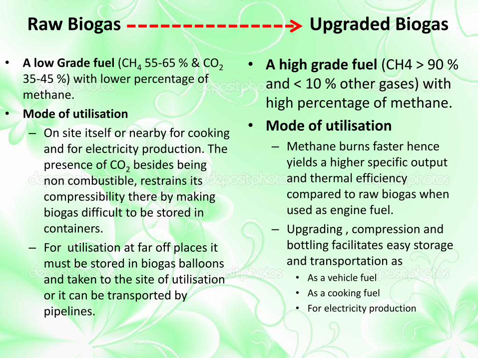
Raw Biogas Upgraded Biogas
• A low Grade fuel (CH4 55-65 % & CO2 35-45 %) with lower percentage of methane.
• Mode of utilisation
– On site itself or nearby for cooking and for electricity production. The presence of CO2 besides being non combustible, restrains its compressibility there by making biogas difficult to be stored in containers.
– For utilisation at far off places it must be stored in biogas balloons and taken to the site of utilisation or it can be transported by pipelines.
• A high grade fuel (CH4 > 90 % and < 10 % other gases) with high percentage of methane.
• Mode of utilisation – Methane burns faster hence
yields a higher specific output and thermal efficiency compared to raw biogas when used as engine fuel.
– Upgrading , compression and bottling facilitates easy storage and transportation as • As a vehicle fuel
• As a cooking fuel
• For electricity production

Upgrading widens the scope of utilization
VERSATILITY OF BIOGAS USE

Pipeline for raw biogas use as a cooking fuel Raw biogas cookstove
Raw biogas for use as a cooking fuel Biogas Engine for electricity production
Utilization of Raw Biogas
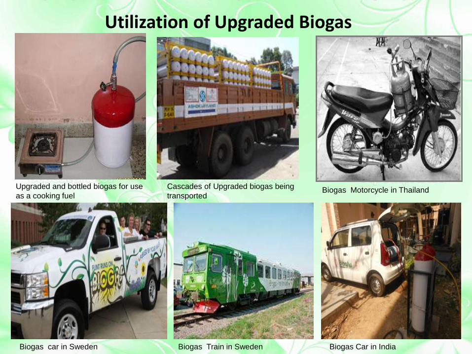
Upgraded and bottled biogas for use
as a cooking fuel
Cascades of Upgraded biogas being
transported Biogas Motorcycle in Thailand
Biogas car in Sweden Biogas Train in Sweden Biogas Car in India
Utilization of Upgraded Biogas

The Solution……………………
……..…..…Low Cost biogas Upgrading

Biogas Enrichment The use of a biogas upgrading or purification process in which the raw
biogas stream like CO2, H2S and moisture are absorbed or scrubbed off, leaving above 90% methane per unit volume of gas.
• Presence of CO2 in biogas poses following problems:
– It lowers the power output from the engine;
– It takes up space when biogas is compressed and stored in cylinder;
– It can cause freezing problems at valves and metering points where the compressed gas undergoes expansion during engine running.
• The traces of H2S produces H2SO4 which corrode the internals of pipes, fittings etc.
• Moisture causes corrosion and decreases heating value of the fuel.

Compression of Biogas
• The energy density of upgraded biogas is comparatively low at ambient pressure and as a result it must be compressed at high pressures (e.g. 200-250 bar) to allow its sufficient storage in bottles/cylinders.
• Compressing biogas • reduces storage space requirements,
• concentrates energy content and
• increases pressure to the level needed to overcome resistance to gas flow.
• Compression can eliminate the mismatch of pressures and guarantee the efficient operation of the equipment.

Removal of CO2 from Biogas
The feasible processes of biogas purification are:
•Absorption into liquid (Physical / Chemical)
•Adsorption on solid surface
•Membrane separation
•Cryogenic separation
Selection of the appropriate process for a particular application
depends on the scale of operation, composition of the gas to be
treated, degree of purity required, capital cost and the need for CO2
recovery.

Comparison between selected parameters for common upgrading processes
Methods
Parameters
High
pressure
water
scrubbing
Chemical
absorption
Pressure
swing
absorption
Membrane
separation
Cryogenic
Gas Pre Cleaning
Requirement
No Yes Yes Yes Yes
Working
Pressure
9-10 Bar 1 Bar 4 – 7 bar 4-7 bar 40 bar
Methane Loss 1– 2 % 1-2 % 1-9 % 10 - 15 % 1-2%
% purity attained
of upgraded
Biogas
95-98 % Upto 99 % 95 - 99 % Upto 90 % Upto 99 %
Heat
requirement
- Required - - -
Operating Cost Low Moderate Moderate Low High
Initial Cost Low Moderate Moderate Moderate High
Process Handling Easy Complex Easy Easy Complex
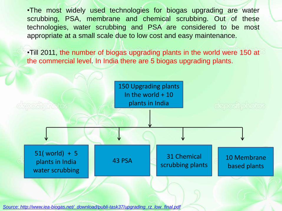
•The most widely used technologies for biogas upgrading are water
scrubbing, PSA, membrane and chemical scrubbing. Out of these
technologies, water scrubbing and PSA are considered to be most
appropriate at a small scale due to low cost and easy maintenance.
•Till 2011, the number of biogas upgrading plants in the world were 150 at
the commercial level. In India there are 5 biogas upgrading plants.
Source: http://www.iea-biogas.net/_download/publi-task37/upgrading_rz_low_final.pdf
150 Upgrading plants In the world + 10
plants in India
51( world) + 5 plants in India
water scrubbing
43 PSA 31 Chemical
scrubbing plants 10 Membrane based plants

DESIGN OF WATER SCRUBBING SYSTEM

Water Scrubbing Method
• Involves the physical absorption of CO2 and H2S in water at high
pressures and regeneration by a release in pressure with very little change in temperature.
• Easiest and cheapest method involving use of pressurized water as an absorbent.
• The absorption process is, thus a counter-current one. The dissolved CO2 and H2S in water are collected at the bottom of the tower.

The amount of CO2 being dissolved in water is determined by 1) The time of contact between biogas and with water - To increase the contact time of the gas with water, counter current mechanism is followed by making water to flow from the top to bottom and raw biogas from bottom to top. 2) the pressure of the raw biogas and water .
Absorption of CO2 in water
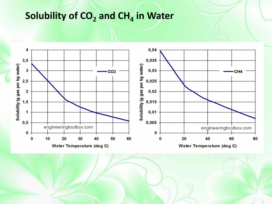
Solubility of CO2 and CH4 in Water
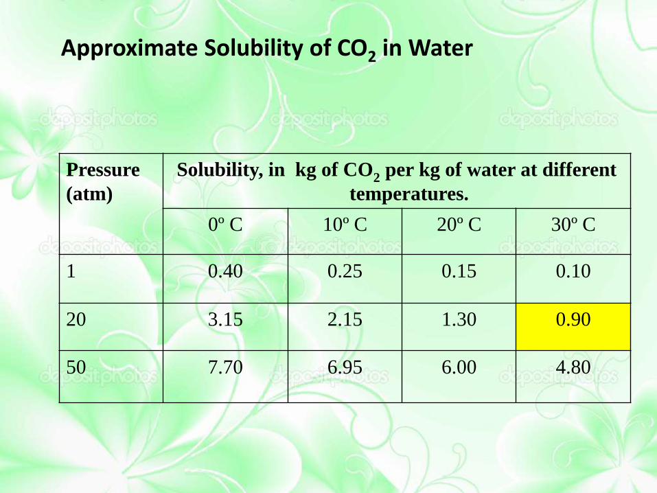
Approximate Solubility of CO2 in Water
Pressure
(atm)
Solubility, in kg of CO2 per kg of water at different
temperatures.
0º C 10º C 20º C 30º C
1 0.40 0.25 0.15 0.10
20 3.15 2.15 1.30 0.90
50 7.70 6.95 6.00 4.80

Packed Bed Scrubber
• Packed bed scrubbers are used for distillation and gas absorption.
• Consists of – a cylindrical column, equipped with a gas inlet and distributing space
at bottom, – a liquid inlet and distributor at top, – liquid and gas outlets at bottom and top respectively and – a supported mass of inert solid shapes.
• The solid shapes are called column packing or filling.
• The packing provides a larger area of contact between the liquid and gas and encourages intimate contact between the phases.
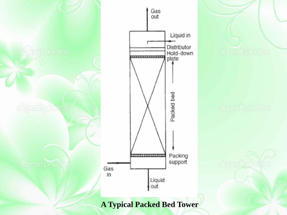
A Typical Packed Bed Tower

Main parameters calculated for the packed bed for a
particular capacity are—
•Working Pressure
•Tower Packing
•Diameter of Packed Bed
•Height of Packed Bed

Working Pressure of the Packed Bed Tower
• The solubility of CO2 & CH4 in water is directly proportional to pressure. As the pressure increases, requirement of water and volume of packed column decreases for a fixed flow rate of biogas.
• Higher working pressure poses the problem of difficult fabrication of tower, difficulty in finding control equipments (sensor, valves etc.) and higher electricity consumption for compression of gas.
• Very low pressure results in excess water requirement and much bigger size of columns.
• Therefore, an intermediate value working pressure of 10 bar (absolute) is chosen in IIT Delhi WS system case.

Tower Packing
• Packing provides the large interface area for the contact of
liquid and gas phase inside the packed tower.
• Has an open structure: low resistance to gas flow.
• Promote uniform liquid distribution on the packing surface.
• Promote uniform vapor gas flow across the column cross-
section.

Types of packing (a) Raschig rings (b) Pall rings (c) Berl saddle ceramic
(d) Intalox saddle ceramic (e) Metal Hypac ( f ) Ceramic, super Intalox

Determination of Diameter (D) and Height (H) of the Packed Bed Column
• The capacity of a packed bed absorption column is depended on its cross-sectional area.
• The column will be designed to operate at the highest economical pressure drop, to ensure good liquid and gas distribution.
• There is no entirely satisfactory method for predicting the height of a transfer unit. In practice the value for a particular packing will depend not only on the physical properties and flow-rates of the gas and liquid, but also on the uniformity of the liquid distribution throughout the column, which is dependent on the column height and diameter.

Biogas Enrichment Plant Parameters
Raw Biogas Flow
Rate
20Nm3/Hr
Vapour phase Biogas (63% CH4, 34%
CO2)
Liquid Phase Water
Working
Pressure
~10 Bar
Working
Temperature
Ambient
Packing Material IMTP
Diameter of
Packed Bed
15cm
Height of Packed
Bed
3.0 m
Water flow rate 4 Nm3/hr
Hence based upon the above calculations and selections the
following input parameters are decided

Water Scrubbing System for Biogas Enrichment at IIT Delhi
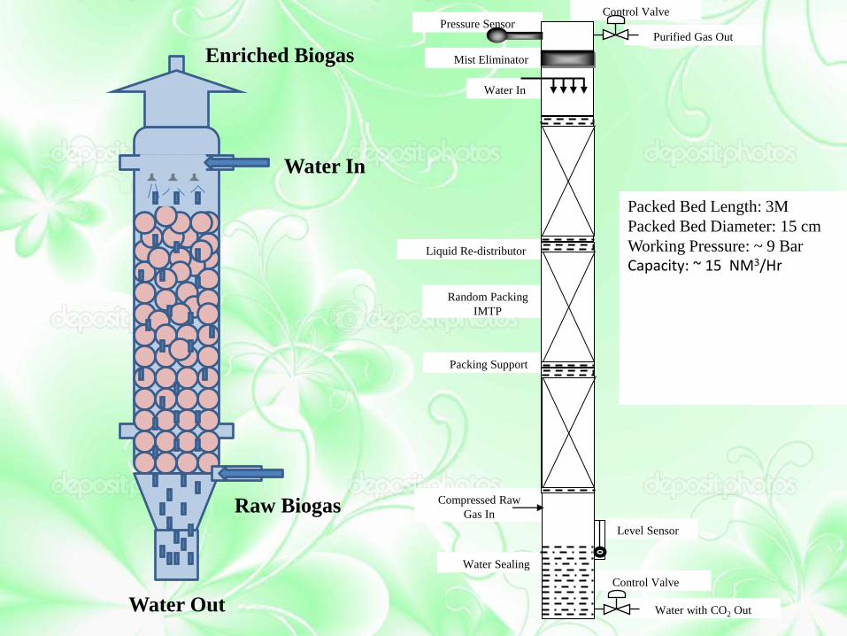
Enriched Biogas
Raw Biogas
Water Out
Water In
Packed Bed Length: 3M
Packed Bed Diameter: 15 cm
Working Pressure: ~ 9 Bar
Capacity: ~ 15 NM3/Hr
Liquid Re-distributor
Packing Support
Random Packing
IMTP
Control Valve
Purified Gas Out
Mist Eliminator
Pressure Sensor
Water In
Water Sealing
Control Valve
Water with CO2 Out
Level Sensor
Compressed Raw
Gas In
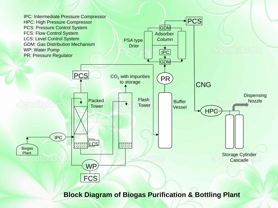
Block Diagram of Biogas Purification & Bottling Plant
IPC: Intermediate Pressure Compressor
HPC: High Pressure Compressor
PCS: Pressure Control System
FCS: Flow Control System
LCS: Level Control System
GDM: Gas Distribution Mechanism
WP: Water Pump
PR: Pressure Regulator
PSA type
Drier
IPC
WP
FCS
LCS
PCS
Biogas
Plant
Packed
Tower
Flash
Tower
GDM
IPC
GDM
Adsorber
Column
PCS
PR
HPC
CNG
Storage Cylinder
Cascade
Dispensing
Nozzle Buffer
Vessel
CO2 with impurities
to storage

Moisture Removal Setup PSA type drier is employed for the removal of moisture. Based on
the concept of selective adsorption of moisture at the outer surface
of adsorbents such as Silica Gel, Activated Alumina, Zeolite
Molecular Sieves etc.
C
Wet Gas In
Auto Drain Valve
Dry
ing
Re
ge
ne
ratio
n
Dry Gas Out Purge Gas
PCS
PSA type Drier for Moisture Removal
Packed Bed Length: 1.5 M
Packed Bed Diameter: 25 mm
Working Pressure: ~7 Bar
Working temperature: Ambient
Capacity: 6 NM3/Hr
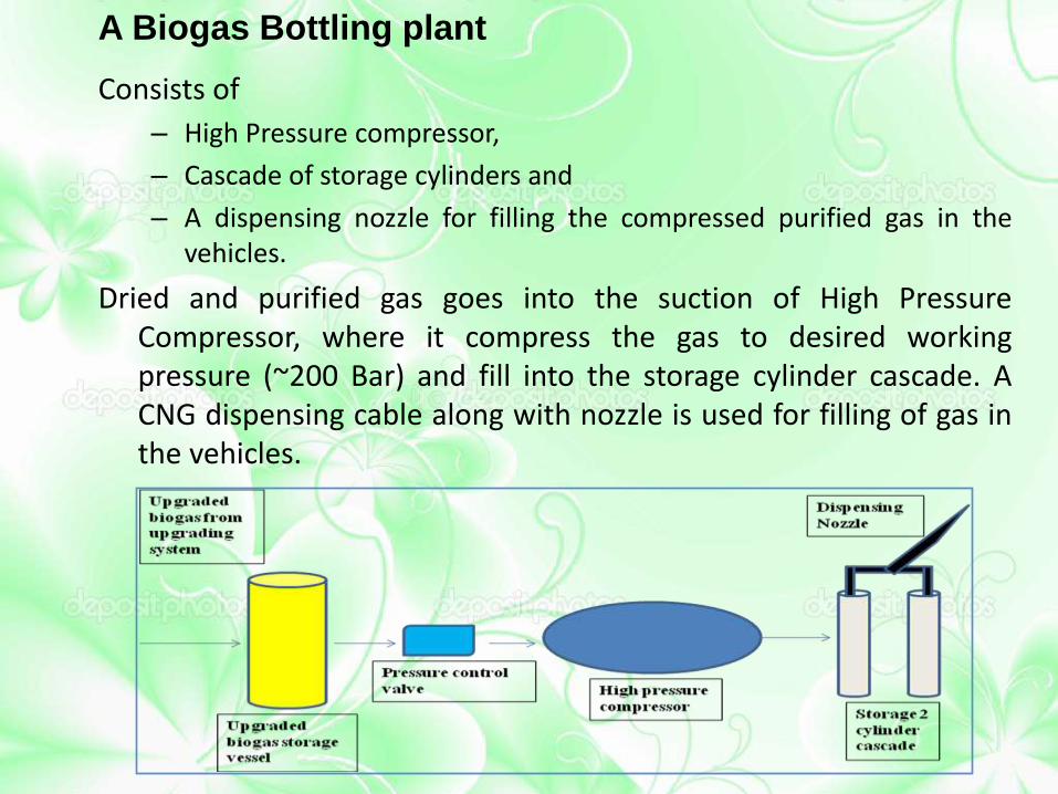
A Biogas Bottling plant
Consists of
– High Pressure compressor,
– Cascade of storage cylinders and
– A dispensing nozzle for filling the compressed purified gas in the vehicles.
Dried and purified gas goes into the suction of High Pressure Compressor, where it compress the gas to desired working pressure (~200 Bar) and fill into the storage cylinder cascade. A CNG dispensing cable along with nozzle is used for filling of gas in the vehicles.

Control System
Is used for maintaining the desired working parameters in the plant. There are mainly three control systems in the plant—
• Water flow rate control
• Gas pressure Control
• Water level control
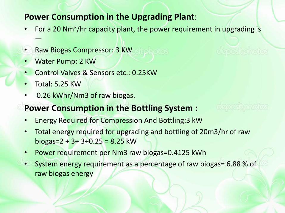
Power Consumption in the Upgrading Plant: • For a 20 Nm3/hr capacity plant, the power requirement in upgrading is
—
• Raw Biogas Compressor: 3 KW
• Water Pump: 2 KW
• Control Valves & Sensors etc.: 0.25KW
• Total: 5.25 KW
• 0.26 kWhr/Nm3 of raw biogas.
Power Consumption in the Bottling System : • Energy Required for Compression And Bottling:3 kW
• Total energy required for upgrading and bottling of 20m3/hr of raw biogas=2 + 3+ 3+0.25 = 8.25 kW
• Power requirement per Nm3 raw biogas=0.4125 kWh
• System energy requirement as a percentage of raw biogas= 6.88 % of raw biogas energy

Biogas Plant at IIT Delhi

New Modified Water Scrubbing Tower at IIT Delhi
Liquid Redistribution unit in
the new modified water
scrubbing tower at IIT Delhi

Water pump Rotameter High Pressure compressor

Two cylinder cascade
for
bottling of upgraded
biogas
Raw and upgraded biogas storage vessels

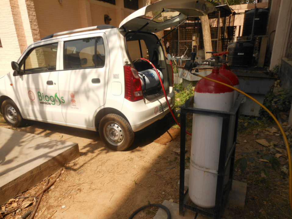
Upgraded Biogas Dispensing System at IIT Delhi

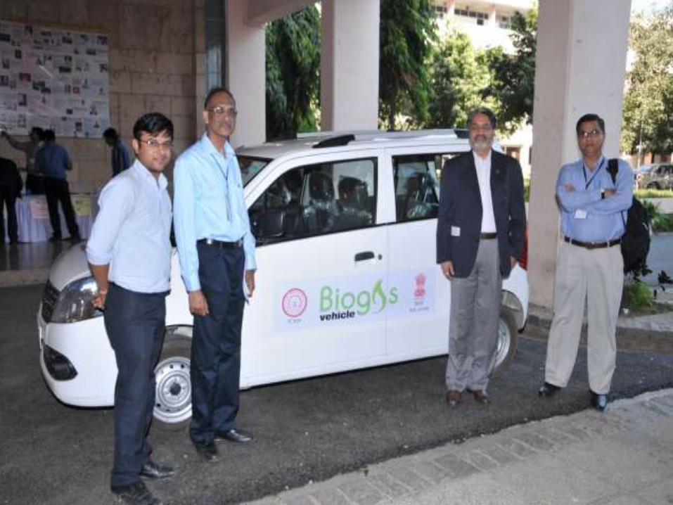
Dispensing upgraded biogas in vehicle

Enriched Biogas Operated Three Wheeler Luggage Carrier
Biogas Dispenser


Results
• A fully automatic plant of 20 Nm3/Hr capacity has been developed
successfully at IIT Delhi.
• Desired composition of purified gas (CH4: 95% (min), H2S: 20 ppm
(max), Moisture: 20 ppm (max) is achieved with a consistent gas
quality.
• Our system is automatically controlled with consistent quality of
enriched gas and a methane loss of about 2%.

Some pilot plants for biogas upgradation
• Rajasthan Go Sewa Sangh Jaipur since 2007
• Madhav Govigyan Sansthan Bhilwara 2008
• Muni Sewa Asharam near Vadodra since 2008
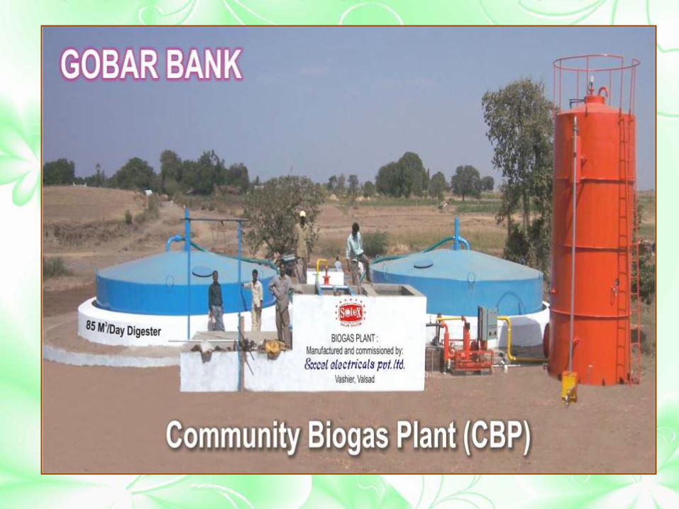
• Community level Biogas plant for piped distribution of gas near Valsad ( Guj) sine 2008
• Shri Krishna Goshala , Ghaziabad since 2009

Biogas upgradation and bottling plant at Nasik, Maharashtra

Water Scrubbing and PSA
system at Nasik
High Pressure Compressor
at Nasik plant
Cylinder Cascade for
bottled biogas

Biogas Upgrading and Bottling Plant at Abhohar, Mukatsar, Punjab 1st Technology demonstration plant BGFP project

Biogas Based Entrepreneurial Avenue Options in India

In developing economies many
entrepreneurial avenues in the biogas sector
are available in :
1)Goshalas,
2) Poultry Farms
3) Dairy farms
4) Cluster of households in villages

In the developing countries the following biogas enterprenurial options are possible
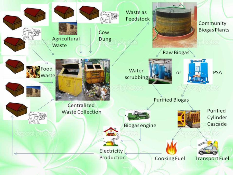
Consider : Cluster of households in villages
Centralized waste collection
system
Rural people put all their wastes- animal
dung and human waste, agricultural
wastes in a centralized collection
place.
The waste is mixed and
shredded then put in the
biogas digesters
Raw biogas is then purified-
Bottled and filled in cascade of cylinders for transportation in
rural areas.
Can be used for cooking or filling in the
vehicle cylinders for transport,
Can be used for generating power
using 100 % biogas engines

Mobile biogas upgrading unit
• Upgradation unit is attached to a vehicle mounted on a trolley. This unit can cater to more than one biogas plants in a cluster.
• The trolley mounted machine with the help of a vehicle can be transported to the digesters located at different locations and raw biogas is filled up in the storage vessel.
• The raw biogas can be upgraded by these mobile units and can fill up CNG cylinders for storage at high pressure and transported to the required place with ease, causing an uninterrupted supply of upgraded biogas

Mobile biogas upgrading unit

Conclusions
