hitachi’s carbon dioxide scrubbing technology with · pdf filehitachi’s carbon...
TRANSCRIPT
1
Hitachi’s Carbon Dioxide Scrubbing Technology with New Absorbent for
Coal-fired Power Plants
Paper # 60
Hirofumi Kikkawa, Yuji Fukuda, Shigehito Takamoto
Kure Research Laboratory Babcock Hitachi K.K. 6-9 Takara-machi, Kure-shi, Hiroshima,
Japan
Toshio Katsube, Takanori Nakamoto, Naoki Oda
Kure Division, Babcock Hitachi K.K. 6-9 Takara-machi, Kure-shi, Hiroshima, Japan
Terufumi Kawasaki, Takashi Sugiura
Hitachi Ltd. Sotokanda 4-14-1, Chiyoda-ku, Tokyou, Japan
Song Wu, Sandhya Eswaran
Hitachi Power Systems America, Ltd. 645 Martinsville Rd., Basking Ridge, NJ, USA
Wolfgang Schreier, Arthur Heberle
Hitachi Power Europe, Schifferstraße 80, 47059 Duisburg, Germany
Brandon Pavlish
Energy and Environmental Research Center, 15 North 23rd Street, Grand Forks, ND, USA
ABSTRACT
Hitachi has been developing a new amine-based scrubbing technology for capturing carbon
dioxide in the flue gas of coal-fired power plants. The development program includes
testing of commercial and new combinations of absorbents and additives. More than thirty
kinds of amines have been evaluated and characterized by both fundamental tests in the
laboratory and slipstream pilot plant tests. The pilot plant tests of the CO2 scrubbing
system were conducted at a coal-fired power plant in co-operation with Tokyo Electric
Power Company. Two thousand hours of continuous operation was achieved with more
than 90 % CO2 reduction on average during the entire operation. Energy consumption
with the original absorbent blend was much less than that with typical MEA. Since then
the CO2 scrubbing system has been further advanced to reduce the energy consumption as
well as absorbent degradation drastically by improving the amine-based absorbent in a
bench-scale test facility. Pilot tests at Energy and Enviromental Research Center (EERC),
University of North Dakota, were conducted in 2010 and the test results indicated high
performance of the improved amine-based absorbent, H3-1. This latest advanced solvent is
also scheduled to be demonstrated in a large mobile test facility at several coal-fired power
plants in Europe starting 2010. In parallel, conceptual designs of the CO2 scrubbing
system for commercial plants up to 800 MWe in size are being developed.
2
INTRODUCTION
Hitachi has been developing new technologies to resolve the global warming issue,
including amine-based scrubbing, oxy-fuel combustion, IGCC with CO2 absorption, and
700 C class advanced ultrasupercritical boiler-turbine system.
Amine-based CO2 separation has been utilized since the 1930s for applications such as
natural gas purification. It is a leading technology expected to be available commercially
within the next decade to enable CCS for coal-fired power stations. However, traditional
amine-based CO2 separation process utilizing conventional solvents is very energy
intensive when applied to coal-fired power plants and also susceptible to solvent
degradation by oxygen, SOx and NO2 in the flue gas, resulting in drastically reduced plant
efficiency and output as well as large operating cost. According to recent DOE/NETL
studies, MEA-based CCS will increase the cost of electricity (COE) of a new pulverized coal
plant by 80-85% and reduce the net plant efficient by about 30%.
To address the above challenges of amine-based CCS for coal power, Babcock Hitachi has
been developing a new amine-based scrubbing technology for capturing carbon dioxide in
the flue gas of coal-fired power plants. The technology features an advanced Air Quality
Control System (AQCS) as a pre-cleaning stage and a low energy-consuming, highly
oxygen-resistant amine-based scrubbing system, and a highly efficient steam extraction
system. One of key components in the AQCS is Flue Gas Desulfurization (FGD). As
demonstrated in various coal-fired plants in the world, the Babcock Hitachi FGD is capable
of reducing sulfur oxides to extremely low levels, which makes the downstream CO2
scrubbing system more efficient and compact1.
The development program includes testing of commercial and new combinations of
absorbents and additives. More than thirty kinds of amine have been evaluated and
characterized by both fundamental tests in the laboratory and slipstream tests of coal-fired
flue gas in a commercial plant. Based on data from these tests a desirable combination of
amine and additives was chosen as an appropriate absorbent for coal-fired flue gas to
achieve high absorption efficiency and low reagent degradation. In addition, the
regenerator adopts a unique design configuration for mixing the solvent and steam, so that
it can be operated with a small amount of steam for heating up CO2-loaded amine. These
innovations are key to lowering the energy consumption of the CO2 capture system.
Pilot plant tests of the CO2 scrubbing system were conducted at a coal-fired power plant in
co-operation with Tokyo Electric Power Company (TEPCO)2. Two-thousand-hour
continuous operation was achieved with more than 90 % CO2 reduction during the entire
operation and energy consumption with the original absorbent blend was (at 2.8
GJ/ton-CO2) much less than that with typical MEA. Since then the CO2 scrubbing system
has been further advanced to reduce the energy consumption as well as absorbent
degradation drastically by improving the amine-based absorbent in a bench-scale test
3
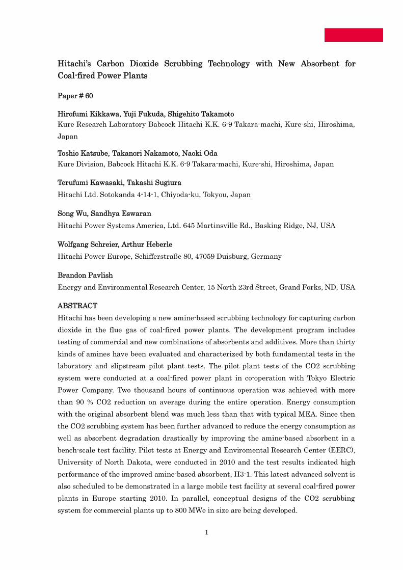
facility of Babcock Hitachi (Figure 1). The new solvent is scheduled to be demonstrated in a
large mobile test facility at several coal-fired power plants in Europe in 2010. In parallel,
conceptual design of the CO2 scrubbing system for 800MWe commercial plants has been
developed.
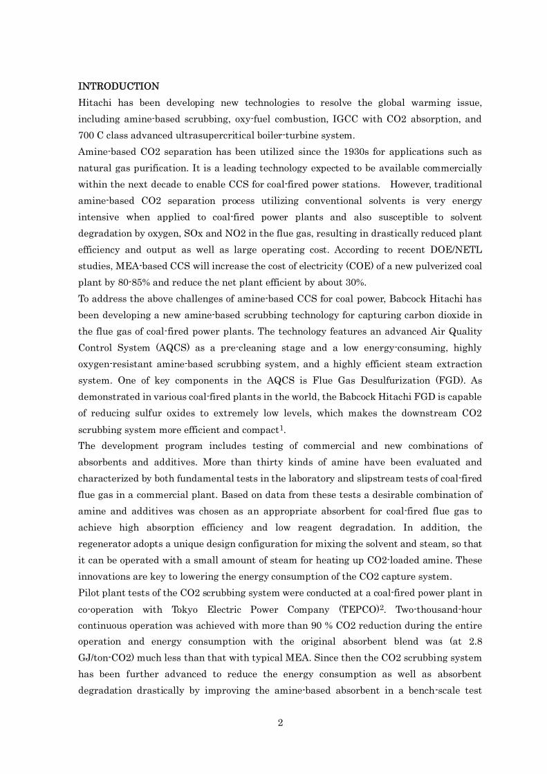
CO2 Capture Process Description
Figure 2 shows a sketch of a post-combustion CO2 capture process. The main system
components are a pre-scrubber, an absorber, a desorber and a reboiler. CO2 scrubbing
system is arranged downstream of the AQCS system. The gas cooler in AQCS is a unique
technology developed by Babcock Hitachi, which controls ESP inlet gas temperature to
remove SO3 across the ESP. The energy recovered by the gas cooler can be utilized for the
CO2 capture system to reduce overall energy consumption.
Since the SOx in flue gas is removed by ESP, FGD and pre-scrubber, Hitachi can provide a
CO2 scrubbing system without a continuous reclaimer.
Pilot Plant 1(1,000m3
N/h)
Bench Scale Apparatus
•Study on additives forabsorbent
• Improvement oftechnology on structuredpacking in absorber
Commercial Plant(800MW)
•Preliminary design•Economic evaluation
Commercial Plant(800MW)
Pilot Plant/Demonstration Plant Test
(1,000 to 100,000 m3N/h)
•Evaluation of design value•Comprehensive performance
evaluation
φ300 absorptiontest facility(500m3
N/h)
Bench scale apparatus(2m3
N/h)
Figure 1 Steps from Bench Scale Apparatus to Commercial Plant
4
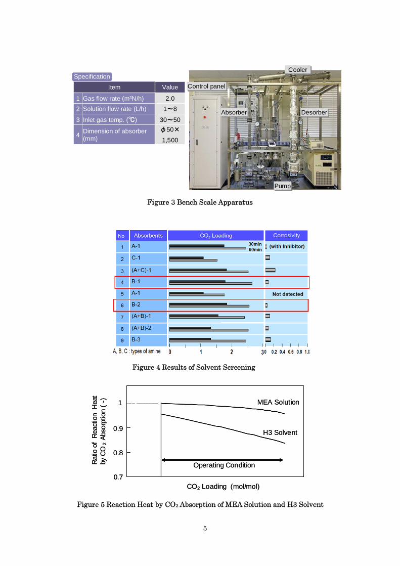
Bench-Scale Tests for Screening Amine Absorbents
High CO2 loading, low corrosivity, low regeneration heat requirement, high
oxidative-resistance and low amine loss are necessary characteristics of a good solvent for
CO2 scrubbing. By screening more than thirty combinations of amines and additives in a 2
m3N/h bench scale apparatus, shown in Figure 3, Babcock-Hitachi has developed a
proprietary amine solution with the above-mentioned characteristics.
Figure 4 shows one set of results of the screening tests. B-1 and B-2 solutions were
superior in terms of both high CO2 loading and low corrosivity. Energy required for solvent
regeneration was also evaluated and compared with that for MEA solution. As shown in
Figure 5, at standard operating conditions, the reaction heat by CO2 absorption of our new
solvent, named H3, was less than that required for MEA by 5 to 15% for the range of
conditions tested.
Desorber100~120℃Heat
exchangerRe-boiler
Absorber40~60℃
Solvent(Amine)
Treated gas
Lean AmineRich Amine
CO2
liquefaction
Storage
Pre-scrubber
Re-claimer
CO2CO2
Figure 2 Post-Combustion CO2 Capture Process
5
4
3
2
1
30~50Inlet gas temp. (℃)
1~8Solution flow rate (L/h)
2.0Gas flow rate (m3N/h)
φ50×
1,500
Dimension of absorber(mm)
ValueItem
4
3
2
1
30~50Inlet gas temp. (℃)
1~8Solution flow rate (L/h)
2.0Gas flow rate (m3N/h)
φ50×
1,500
Dimension of absorber(mm)
ValueItem
Specification
Control panelControl panel
AbsorberAbsorber DesorberDesorber
PumpPump
CoolerCooler
Control panelControl panel
AbsorberAbsorber DesorberDesorber
PumpPump
CoolerCooler
1
0.8
0.7
0.9
MEA Solution
H3 Solvent
CO2 Loading (mol/mol)
Ra
tioof
React
ion
Heat
byC
O2
Abso
rptio
n(
-)
Operating Condition
1
0.8
0.7
0.9
MEA Solution
H3 Solvent
CO2 Loading (mol/mol)
Ra
tioof
React
ion
Heat
byC
O2
Abso
rptio
n(
-)
Operating Condition
Figure 3 Bench Scale Apparatus
Figure 4 Results of Solvent Screening
Figure 5 Reaction Heat by CO2 Absorption of MEA Solution and H3 Solvent
6
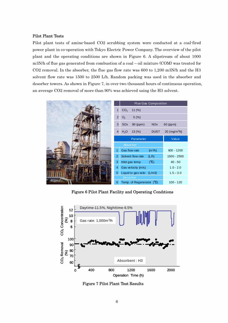
Pilot Plant Tests
Pilot plant tests of amine-based CO2 scrubbing system were conducted at a coal-fired
power plant in co-operation with Tokyo Electric Power Company. The overview of the pilot
plant and the operating conditions are shown in Figure 6. A slipstream of about 1000
m3N/h of flue gas generated from combustion of a coal – oil mixture (COM) was treated for
CO2 removal. In the absorber, the flue gas flow rate was 600 to 1,200 m3N/h and the H3
solvent flow rate was 1500 to 2500 L/h. Random packing was used in the absorber and
desorber towers. As shown in Figure 7, in over two thousand hours of continuous operation,
an average CO2 removal of more than 90% was achieved using the H3 solvent.
Figure 6 Pilot Plant Facility and Operating Conditions
4
3
2
1
SOx 80 (ppm) NOx 60 (ppm)
O2 5 (%)
CO2 11 (%)
H2O 13 (%) DUST 20 (mg/m3N)
Flue Gas Composition
Liquid to gas ratio (L/m3)5
Desorber
Absorber
Temp. of Regenerator (℃)6
Gas velocity (m/s)4
3
2
1
Inlet gas temp. (℃)
Solvent flow rate (L/h)
Gas flow rate (m3/h)
Parameter
1.5 – 3.0
100 - 120
1.0 - 2.0
40 - 50
1500 - 2500
600 - 1200
Value
Operation Time (h)
CO
2R
em
oval
(%)
CO
2C
on
ce
ntr
atio
n(%
)
100
90
60
80
70
0 400 800 1200 1600 2000
Absorbent : H3
Gas rate: 1,000m3/h
12
10
6
8
Operation Time (h)
CO
2R
em
oval
(%)
CO
2C
on
ce
ntr
atio
n(%
)
100
90
60
80
70
0 400 800 1200 1600 2000
Absorbent : H3
Gas rate: 1,000m3/h
12
10
6
8
12
10
6
8
Daytime-11.5%, Nighttime-6.5%
Figure 7 Pilot Plant Test Results
7
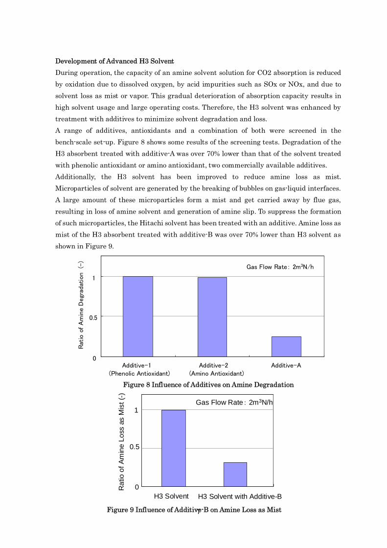
Development of Advanced H3 Solvent
During operation, the capacity of an amine solvent solution for CO2 absorption is reduced
by oxidation due to dissolved oxygen, by acid impurities such as SOx or NOx, and due to
solvent loss as mist or vapor. This gradual deterioration of absorption capacity results in
high solvent usage and large operating costs. Therefore, the H3 solvent was enhanced by
treatment with additives to minimize solvent degradation and loss.
A range of additives, antioxidants and a combination of both were screened in the
bench-scale set-up. Figure 8 shows some results of the screening tests. Degradation of the
H3 absorbent treated with additive-A was over 70% lower than that of the solvent treated
with phenolic antioxidant or amino antioxidant, two commercially available additives.
Additionally, the H3 solvent has been improved to reduce amine loss as mist.
Microparticles of solvent are generated by the breaking of bubbles on gas-liquid interfaces.
A large amount of these microparticles form a mist and get carried away by flue gas,
resulting in loss of amine solvent and generation of amine slip. To suppress the formation
of such microparticles, the Hitachi solvent has been treated with an additive. Amine loss as
mist of the H3 absorbent treated with additive-B was over 70% lower than H3 solvent as
shown in Figure 9.
0
0.5
1
Additive-1(Phenolic Antioxidant)
Additive-2(Amino Antioxidant)
Additive-A
Ratio
ofAmineDegradation
(-)
Gas Flow Rate: 2m3N/h
Figure 8 Influence of Additives on Amine Degradation
Figure 9 Influence of Additive-B on Amine Loss as Mist
0
0.5
1
Ra
tioo
fA
min
eL
oss
as
Mis
t(-
)
H3 Solvent H3 Solvent with Additive-B
Gas Flow Rate: 2m3N/h
8
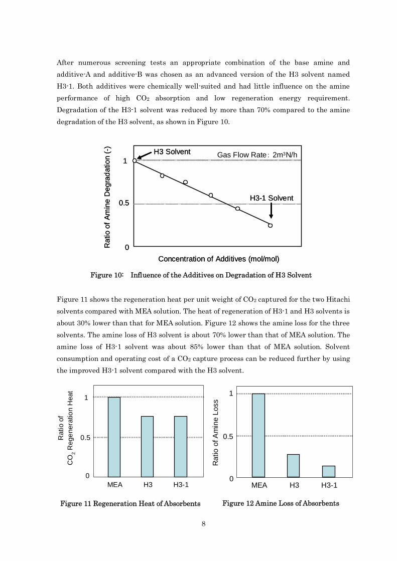
After numerous screening tests an appropriate combination of the base amine and
additive-A and additive-B was chosen as an advanced version of the H3 solvent named
H3-1. Both additives were chemically well-suited and had little influence on the amine
performance of high CO2 absorption and low regeneration energy requirement.
Degradation of the H3-1 solvent was reduced by more than 70% compared to the amine
degradation of the H3 solvent, as shown in Figure 10.
Figure 11 shows the regeneration heat per unit weight of CO2 captured for the two Hitachi
solvents compared with MEA solution. The heat of regeneration of H3-1 and H3 solvents is
about 30% lower than that for MEA solution. Figure 12 shows the amine loss for the three
solvents. The amine loss of H3 solvent is about 70% lower than that of MEA solution. The
amine loss of H3-1 solvent was about 85% lower than that of MEA solution. Solvent
consumption and operating cost of a CO2 capture process can be reduced further by using
the improved H3-1 solvent compared with the H3 solvent.
Figure 10: Influence of the Additives on Degradation of H3 Solvent
Figure 11 Regeneration Heat of Absorbents Figure 12 Amine Loss of Absorbents
H3MEA H3-1
1
0.5
0
Ra
tio
ofA
min
eL
oss
Concentration of Additives (mol/mol)
Ratio
of
Am
ine
Degra
dation
(-)
1
0.5
0
H3-1 Solvent
H3 Solvent
Concentration of Additives (mol/mol)
Ratio
of
Am
ine
Degra
dation
(-)
1
0.5
0
H3-1 Solvent
H3 Solvent Gas Flow Rate: 2m3N/h
H3MEA H3-1
Ratio
of
CO
2R
ege
nera
tio
nH
eat
1
0.5
0
9
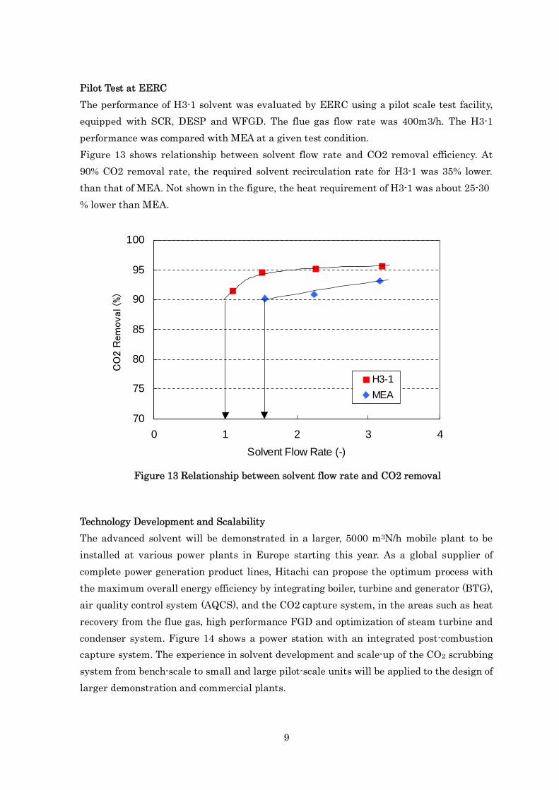
Pilot Test at EERC
The performance of H3-1 solvent was evaluated by EERC using a pilot scale test facility,
equipped with SCR, DESP and WFGD. The flue gas flow rate was 400m3/h. The H3-1
performance was compared with MEA at a given test condition.
Figure 13 shows relationship between solvent flow rate and CO2 removal efficiency. At
90% CO2 removal rate, the required solvent recirculation rate for H3-1 was 35% lower.
than that of MEA. Not shown in the figure, the heat requirement of H3-1 was about 25-30
% lower than MEA.
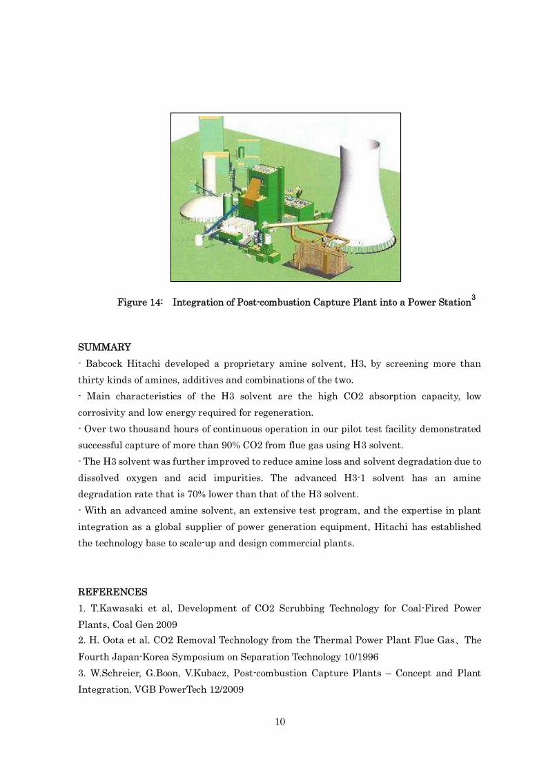
Technology Development and Scalability
The advanced solvent will be demonstrated in a larger, 5000 m3N/h mobile plant to be
installed at various power plants in Europe starting this year. As a global supplier of
complete power generation product lines, Hitachi can propose the optimum process with
the maximum overall energy efficiency by integrating boiler, turbine and generator (BTG),
air quality control system (AQCS), and the CO2 capture system, in the areas such as heat
recovery from the flue gas, high performance FGD and optimization of steam turbine and
condenser system. Figure 14 shows a power station with an integrated post-combustion
capture system. The experience in solvent development and scale-up of the CO2 scrubbing
system from bench-scale to small and large pilot-scale units will be applied to the design of
larger demonstration and commercial plants.
Figure 13 Relationship between solvent flow rate and CO2 removal
70
75
80
85
90
95
100
0 1 2 3 4
Solvent Flow Rate (-)
CO2Removal(%)
H3-1
MEA
10
SUMMARY
- Babcock Hitachi developed a proprietary amine solvent, H3, by screening more than
thirty kinds of amines, additives and combinations of the two.
- Main characteristics of the H3 solvent are the high CO2 absorption capacity, low
corrosivity and low energy required for regeneration.
- Over two thousand hours of continuous operation in our pilot test facility demonstrated
successful capture of more than 90% CO2 from flue gas using H3 solvent.
- The H3 solvent was further improved to reduce amine loss and solvent degradation due to
dissolved oxygen and acid impurities. The advanced H3-1 solvent has an amine
degradation rate that is 70% lower than that of the H3 solvent.
- With an advanced amine solvent, an extensive test program, and the expertise in plant
integration as a global supplier of power generation equipment, Hitachi has established
the technology base to scale-up and design commercial plants.
REFERENCES
1. T.Kawasaki et al, Development of CO2 Scrubbing Technology for Coal-Fired Power
Plants, Coal Gen 2009
2. H. Oota et al. CO2 Removal Technology from the Thermal Power Plant Flue Gas、The
Fourth Japan-Korea Symposium on Separation Technology 10/1996
3. W.Schreier, G.Boon, V.Kubacz, Post-combustion Capture Plants – Concept and Plant
Integration, VGB PowerTech 12/2009
Figure 14: Integration of Post-combustion Capture Plant into a Power Station3