water heating - w.l. engler promax power vent water heaters have been engineered to maximize...
TRANSCRIPT

Water H
eating
3
MANUFACTURERS INDEX, SECTION 3A. O. SMITH . . . . . . . . . . . . . . . . . . . . . . . . . . . . . . . . . . . . . . . . . . . . . . . . 3-1 – 3-23
WATTS VALVE . . . . . . . . . . . . . . . . . . . . . . . . . . . . . . . . . . . . . . . . . . . . . . . . . . . 3-24
Wat
er H
eati
ng
3
3-1
INTELLIGENT CONTROL LOGICThe internal microprocessor provides enhanced operatingparameters and tighter differentials for precise sensing andfaster heating response to optimize performance.
SELF-POWERED ELECTRONIC GAS VALVEUses a thermopile to generate the power needed to operate theelectronic gas control without requiring an external powersource.
DIAGNOSTICSThe electronic gas control incorporates an LED status indicatorthat monitors system operation & service diagnostics.
DYNACLEAN™ DIFFUSER DIP TUBEHelps reduce lime and sediment buildup, maximizes hot wateroutput. Made from long-lasting PEX cross-linked polymer.
COREGARD™ ANODE RODA. O. Smith’s exclusive aluminum anode has a stainless steelcore, protects tank against corrosion.
GREEN CHOICE® GAS BURNERPatented “Eco-Friendly” design reduces NOx emissions by upto 33% and complies with less than 40 ng/j requirements forlow NOx emissions.
PUSH-BUTTON PIEZO IGNITORMakes lighting pilot fast and easy with one-hand push-buttonspark ignition.
DURABLE, TAMPER-RESISTANT BRASS DRAIN VALVE
BLUE DIAMOND® GLASS COATINGProvides superior corrosion resistance compared to industry-standard glass lining.
CSA CERTIFIED AND ASME RATED T&P RELIEF VALVETop-mounted T&P relief valve available as option.
CODE COMPLIANCEMeets UBC, CEC, SBCC, HUD and BOCA National Codes.Meets the thermal efficiency and standby loss requirements ofthe U.S. Department of Energy and current edition ofASHRAE/IESNA 90.1 and meets the Federal Energy EfficiencyStandards effective January 20, 2004, according to the NationalAppliance Energy Conservation Act (NAECA) of 1992.
DESIGN-CERTIFIED BY CSA INTERNATIONALAccording to ANSI Z21.10.1 - CSA 4.1 standards governingstorage-type water heaters.
FLAMMABLE VAPOR IGNITION RESISTANT COMPLIANTDESIGNSee below.
6-YEAR LIMITED TANK AND PARTS WARRANTYFor complete information, consult written warranty or A. O.Smith.
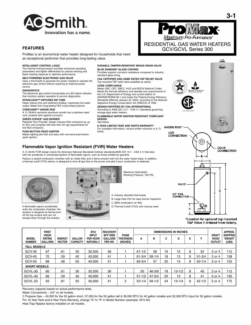
RESIDENTIAL GAS WATER HEATERSGCV/GCVL Series 300
Flammable Vapor Ignition Resistant (FVIR) Water HeatersA. O. Smith FVIR design meets the American National Standards Institute standards(ANSI Z21.10.1 - CSA 4.1) that dealwith the accidental or unintended ignition of flammable vapors, such as those emitted by gasoline.
Feature a sealed combustion chamber with air intake filter and a flame arrestor built into the water heater base. In addition,a thermal cutoff (TCO) device, is designed to shut off gas flow to the burner and pilot if poor combustion is detected.
FIRST BTU RECOVERY APPROX.HOUR INPUT 90ºF RISE FOAM DRAFT SHIPPING
MODEL RATING ENERGY GALLON PER HOUR GALLONS THICKNESS A B C D E F HOOD WEIGHTNUMBER GALLONS FACTOR CAPACITY NATURAL† PER HR. (INCHES) OUTLET (LBS)
TALL MODELS
GCV-30 67 .61 30 35,500 36 1 61-1/2 58 16 13 8 52 3 or 4 112
GCV-40 70 .59 40 40,000 41 1 61-3/4 58-1/4 18 13 8 51-3/4 3 or 4 138
GCV-50 88 .58 50 40,000 41 1 60-3/4 57 20 13 8 50-1/4 3 or 4 153
SHORT MODELS
GCVL-30 60 .61 30 35,500 36 1 50 46-3/8 18 13-1/2 8 40 3 or 4 112
GCVL-40 66 .59 40 40,000 41 1 51-1/2 47-3/4 20 13 8 41 3 or 4 135
GCVL-50 93 .61 50 40,000 41 2 53-1/4 49-1/2 24 13-1/4 8 42-1/2 3 or 4 175
Recovery capacity based on actual performance tests.Water Connections – 3/4" on all models.† Propane Gas – 40,000 for the 50 gallon short, 37,000 for the 50 gallon tall & 36,000 BTU for 40 gallon models and 32,000 BTU input for 30 gallon models.For 10-Year Tank and 6-Year Parts Warranty, change “G” to “X” in Model Number (example: XCV-40).Heat Trap Nipples factory-installed on all models.
DIMENSIONS IN INCHES
If flammable vapors accidentallyenter the combustion chamber, thearrestor is designed so flames burnoff the top surface and can notescape down through the arrestor.
FEATURESProMax is an economical water heater designed for households that need an exceptional performer that provides long-lasting value.
A. Industry standard thermopile
B. Large View Port for easy burner inspection
C. 3600 combustion air filter
D. Thermal Cutoff (TCO) with manual reset
Maximum HydrostaticWorking Pressure: 150 PSI.
3-2
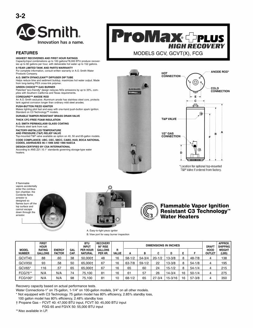
FEATURESHIGHEST RECOVERIES AND FIRST HOUR RATINGSCapacity/input combinations up to 100 gallons/78,000 BTU produce recover-ies up to 82 gallons per hour, with deliverable hot water up to 152 gallons.
6-YEAR LIMITED TANK AND PARTS WARRANTYFor complete information, consult written warranty or A.O. Smith WaterProducts Company.
A.O. SMITH DYNACLEAN™ DIFFUSER DIP TUBEHelps reduce lime and sediment buildup, maximizes hot water output. Madefrom long-lasting PEX cross-link polymer.
GREEN CHOICE™ GAS BURNERPatented “eco-friendly” design reduces NOx emissions by up to 33%, com-plies with Southern California and Texas requirements.
COREGARD™ ANODE RODAn A.O. Smith exclusive. Aluminum anode has stainless steel core, protectstank against corrosion longer than ordinary mild steel anodes.
PUSH-BUTTON PIEZO IGNITERMakes lighting pilot fast and easy with one-hand push-button spark ignition.Standard on C3 Technology™ models.
DURABLE TAMPER-RESISTANT BRASS DRAIN VALVE
THICK CFC-FREE FOAM INSULATION
A.O. SMITH PERMAGLAS® GLASS COATINGProtects steel tank from rust.
FACTORY-INSTALLED TEMPERATUREAND PRESSURE (T&P) RELIEF VALVETop-mounted T&P valve available as option on 40, 50 and 65-gallon models.
CODE COMPLIANCE: UBC, CEC, SBCC, CABO, HUD, BOCA NATIONALCODES, ASHRAE/IES 90.1-1999 AND 1990 NAECA
DESIGN-CERTIFIED BY CSA INTERNATIONALAccording to ANS Z21.10.1* standards governing storage-type waterheaters.
If flammablevapors accidentallyenter the combus-tion chamber, theCorderite flamearrestor isdesigned soflames burn off thetop surface andcannot escapedown through thearrestor.
A. Easy-to-light piezo igniter
B. View port for easy burner inspection
FIRST BTU RECOVERY APPROX.HOUR INPUT 90º RISE DRAFT SHIPPING
MODEL RATING ENERGY GAL PER HOUR GALLONS R HOOD WEIGHTNUMBER GALLONS FACTOR CAP. NATURAL PER HR. VALUE A B C D E F OUTLET (LBS)
GCVT40 88 .60 38 50,000† 48 16 58-1/2 54-3/4 20-1/2 13-3/8 8 48-7/8 4 138
GCVX50 93 .58 50 65,000† 67 16 63-7/8 59-1/2 22 13-3/8 8 54-1/8 4 195
GCV65* 116 .57 65 65,000† 67 16 65 60 24 15-1/2 8 54-1/4 4 215
FCG75** N/A N/A 74 75,100 81 16 61 57 26 14-3/4 16 50-1/4 4 275
FCG100* N/A N/A 98 75,100 81 10 68-1/2 65 27-3/4 15-3/16 16 57-3/8 4 350
DIMENSIONS IN INCHES
Recovery capacity based on actual performance tests.Water Connections-1" on 75-gallon, 1-1/4" on 100-gallon models, 3/4" on all other models.* Not equipped with C3 Technology. 75 gallon model has 80% efficiency, 2.85% standby loss,
100 gallon model has 80% efficiency, 2.48% standby loss† Propane Gas – FCVT 40: 47,000 BTU input, FCVT 50: 45,000 BTU input
FGG 65 and FGVX 50: 55,000 BTU input**Also available in LP.
MODELS GCV, GCVT(X), FCG
3-3
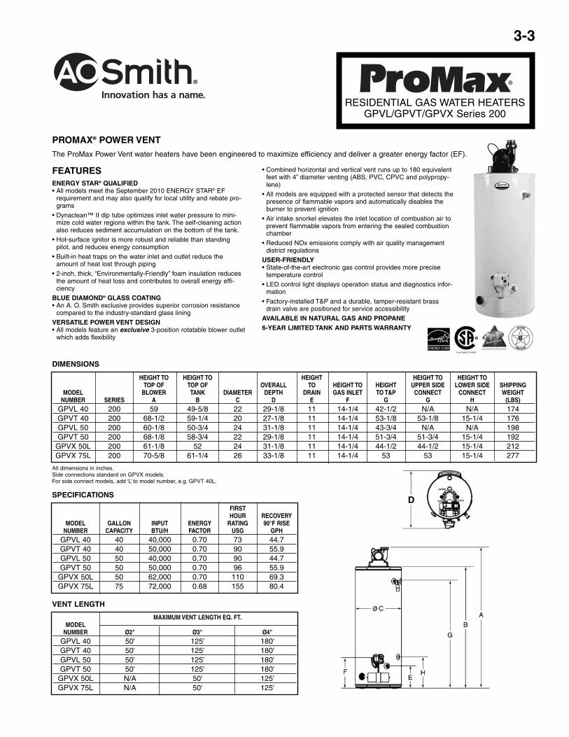
All dimensions in inches.Side connections standard on GPVX models.For side connect models, add ‘L’ to model number, e.g. GPVT 40L.
FEATURESENERGY STAR® QUALIFIED• All models meet the September 2010 ENERGY STAR® EF
requirement and may also qualify for local utility and rebate pro-grams
• Dynaclean™ II dip tube optimizes inlet water pressure to mini-mize cold water regions within the tank. The self-cleaning actionalso reduces sediment accumulation on the bottom of the tank.
• Hot-surface ignitor is more robust and reliable than standingpilot, and reduces energy consumption
• Built-in heat traps on the water inlet and outlet reduce theamount of heat lost through piping
• 2-inch, thick, “Environmentally-Friendly” foam insulation reducesthe amount of heat loss and contributes to overall energy effi-ciency
BLUE DIAMOND® GLASS COATING• An A. O. Smith exclusive provides superior corrosion resistance
compared to the industry-standard glass lining
VERSATILE POWER VENT DESIGN• All models feature an exclusive 3-position rotatable blower outlet
which adds flexibility
• Combined horizontal and vertical vent runs up to 180 equivalentfeet with 4” diameter venting (ABS, PVC, CPVC and polypropy-lene)
• All models are equipped with a protected sensor that detects thepresence of flammable vapors and automatically disables theburner to prevent ignition
• Air intake snorkel elevates the inlet location of combustion air toprevent flammable vapors from entering the sealed combustionchamber
• Reduced NOx emissions comply with air quality managementdistrict regulations
USER-FRIENDLY• State-of-the-art electronic gas control provides more precise
temperature control
• LED control light displays operation status and diagnostics infor-mation
• Factory-installed T&P and a durable, tamper-resistant brassdrain valve are positioned for service accessibility
AVAILABLE IN NATURAL GAS AND PROPANE6-YEAR LIMITED TANK AND PARTS WARRANTY
RESIDENTIAL GAS WATER HEATERSGPVL/GPVT/GPVX Series 200
HEIGHT TO HEIGHT TO HEIGHT HEIGHT TO HEIGHT TOTOP OF TOP OF OVERALL TO HEIGHT TO HEIGHT UPPER SIDE LOWER SIDE SHIPPING
MODEL BLOWER TANK DIAMETER DEPTH DRAIN GAS INLET TO T&P CONNECT CONNECT WEIGHTNUMBER SERIES A B C D E F G G H (LBS)
GPVL 40 200 59 49-5/8 22 29-1/8 11 14-1/4 42-1/2 N/A N/A 174GPVT 40 200 68-1/2 59-1/4 20 27-1/8 11 14-1/4 53-1/8 53-1/8 15-1/4 176GPVL 50 200 60-1/8 50-3/4 24 31-1/8 11 14-1/4 43-3/4 N/A N/A 198GPVT 50 200 68-1/8 58-3/4 22 29-1/8 11 14-1/4 51-3/4 51-3/4 15-1/4 192
GPVX 50L 200 61-1/8 52 24 31-1/8 11 14-1/4 44-1/2 44-1/2 15-1/4 212GPVX 75L 200 70-5/8 61-1/4 26 33-1/8 11 14-1/4 53 53 15-1/4 277
DIMENSIONS
PROMAX® POWER VENTThe ProMax Power Vent water heaters have been engineered to maximize efficiency and deliver a greater energy factor (EF).
FIRSTHOUR RECOVERY
MODEL GALLON INPUT ENERGY RATING 90°F RISENUMBER CAPACITY BTU/H FACTOR USG GPH
GPVL 40 40 40,000 0.70 73 44.7GPVT 40 40 50,000 0.70 90 55.9GPVL 50 50 40,000 0.70 90 44.7GPVT 50 50 50,000 0.70 96 55.9
GPVX 50L 50 62,000 0.70 110 69.3GPVX 75L 75 72,000 0.68 155 80.4
SPECIFICATIONS
MAXIMUM VENT LENGTH EQ. FT.MODEL
NUMBER Ø2" Ø3" Ø4"GPVL 40 50' 125' 180'GPVT 40 50' 125' 180'GPVL 50 50' 125' 180'GPVT 50 50' 125' 180'
GPVX 50L N/A 50' 125'GPVX 75L N/A 50' 125'
VENT LENGTH

3-4
VERTEX™
90% EFFICIENCY POWER VENTWATER HEATER
MODEL GPHE-50
NATURAL GAS PROPANE GAS A B C D E F GVent GPH GPH Hgt. to Side Side Hgt. Gas Approx.
Gal. Pipe 90 º 90 º Top of Out- In- Drain Inlet/ Ship.Model Cap. Dia. Input Rise Input Rise Hgt. Jacket let Let Valve Diameter Wt.
GPHE-50 50 3" 80,000 86 80,000 86 70-5/8 68-1/4 52 21 9-1/8 12 22 210
FEATURESHELICAL INTERNAL HEAT EXCHANGER• Positioned in the center of the tank, surrounded by water to
virtually eliminate radiant heatloss from the chamber
• Achieves 90% thermal efficiency which saves money onoperating costs compared to a standard 78% efficient gaswater heater
POWER VENTS USING PVC PIPE• Combined vertical and horizontal vent runs terminating
through an outside wall, using Schedule 40 PVC
• 2" pipe, vents up to 25 equivalent feet
• 3" pipe, vents up to 65 equivalent feet
• 4" pipe, vents up to 128 equivalent feet
MODULAR BLOWER• Equipped with 120 volt, 60 Hz electrical system (rating 5
amps or less), 6-foot cord with standard 3-prong connector
• 2" PVC pipe, elbows and condensate drain supplied to con-nect heat exchanger outlet to blower
• PVC Vent Attenuation Assembly (VAA) supplied
SIDE-MOUNTED HOT AND COLD RECIRCULATING TAPS• Allows Vertex to be installed as part of combination space
heating/water heating applications or any system requiringa recirculating hot water loop, including radiant floor heatingINTELLI-VENT™**
GAS CONTROL• Equipped with nearly indestructible silicon nitride hot sur-
face ignitor
• Advanced electronics for more precise control of water tem-perature and easy to understand system diagnostics
COMMERCIAL GRADE GLASS LINING• A. O. Smith PermaGlas® Ultra Coat™ process provides
superior protection against corrosion
• Protects all interior tank surfaces including inside and out-side of helical heat exchanger
TWO HEAVY-DUTY ANODE RODS• Provide maximum protection against corrosionGREEN
CHOICE® GAS BURNER
• Patented “Eco-Friendly” design reduces NOx emissions byup to 33%
CERTIFIED AND ASME RATED T&P RELIEF VALVEMAXIMUM HYDROSTATIC WORKING PRESSURE: 150 PSI®Residential Gas Water Heaters• Spiral heat exchanger reduces scale and sediment fromforming on water-side surface, which can reduce energy effi-ciency over time
®
MAXIMUM VENT DISTANCEMODEL BTU (Total Equivalent Feet)
NUMBER INPUT 2" Pipe 3" Pipe 4" PipeGPHE-50 76,000 25’ 65' 128'
If flammablevapors accidentallyenter the combus-tion chamber, theCorderite flamearrestor isdesigned soflames burn off thetop surface andcannot escapedown through thearrestor.

3-5
SPECIALTYELECTRIC WATER HEATERS
CompactModels
PROMAX® SPECIALTY ELECTRIC FEATURES
COMPACT ELECTRIC WATER HEATERSCompact design, side-mounted plumbing and electrical connections(optional top-mounted connections). Designed for installation undera counter, in a crawl space or in other tight spaces. Tank capacitiesrange from 6 through 20-gallons and offer single heating elementand durable tamper-resistance brass drain valve.
POINT-OF-USE ELECTRIC WATER HEATERDesigned for low-demand, point-of-use applications, such as officelavatories or buildings with remote restrooms. Models have 2-1/2 gal-lon tank capacity and are equipped with a single heating element.Includes a standard 110/120V cord set with 3-prong plug and wall-mounting brackets for easy installation.
CSA CERTIFIED AND ASME RATED T&P RELIEF VALVE
CODE COMPLIANCEMeets or exceeds the Federal energy efficiency standards effectiveJanuary 20, 2004, according to the National Appliance EnergyConservation Act (NAECA) of 1992. Also meets or exceeds the stand-by loss requirements of the U. S. Department of Energy and currentedition of ASHRAE/IESNA 90.1.
6-YEAR LIMITED TANK AND PARTS WARRANTYFor complete information, consult written warranty orA. O. Smith Water Products Company.
FIRST ELEMENT WATTAGE DIMENSIONS IN INCHES APPROX.MODEL HOUR ENERGY GALLON RECOVERY R SHIPPING
NUMBER RATING FACTOR CAPACITY STANDARD MAXIMUM 90ºF RISE VALUE A B C WEIGHTGALLONS 120V 240V (LBS.)
EJC-6 N/A N/A 6 1650 3000 8 8 15-1/4 10-3/4† 14-1/4 31EJC-10 N/A N/A 10 1650 6000 8 8 18-1/4 12-1/4† 16 45
EJCS-20 N/A N/A 19 2500 6000 11 8 24-3/4 18-5/8† 18 65EJCT-20 N/A N/A 19.9 2500 6000 11 8 31-5/8 25-3/4† 16 62
FIRST ELEMENT WATTAGE DIMENSIONS IN INCHES APPROX.MODEL HOUR ENERGY GALLON RECOVERY R SHIPPING
NUMBER RATING FACTOR CAPACITY STANDARD MAXIMUM 90ºF RISE VALUE A B C WEIGHTGALLONS 240V 240V (LBS.)
ECJ-30 37 .93 29 4500 6000 21 16 30 22-3/4† 22 100ECJN-40 43 .92 38 4500 6000 21 12 31-1/4 24-5/8† 23 131
LOWBOY SIDE-CONNECT MODELS
COMPACT MODELS
FIRST APPROX.MODEL HOUR ENERGY GALLON RECOVERY R DIMENSIONS IN INCHES SHIPPING
NUMBER RATING FACTOR CAPACITY ELEMENT WATTAGE 90ºF RISE VALUE WEIGHTGALLONS A B C (LBS.)
EJC-2 N/A N/A 2.5 1500@120V 7 8 13-3/4 11 13-3/4 18
POINT-OF-USE MODEL
Point-Of-Use

3-6
ENERGY SAVERELECTRIC
RESIDENTIAL WATER HEATERSMODELS ECS, ECT, ELJC, ECL(N)
FEATURESTALL, SHORT AND LOWBOY (TOP CONNECT)MODELS AVAILABLE.
A. O. SMITH DYNACLEAN™ DIFFUSER DIP TUBE
Helps reduce lime and sediment buildup, maximizes hotwater output.
Made from long-lasting PEX cross-link polymer.
COREGARD™ ANODE ROD
Aluminum anode with stainless steel core protects tankagainst corrosion longer than ordinary mild steel anodes.
DURABLE TAMPER-RESISTANT BRASS DRAIN VALVE
A. O. SMITH PERMAGLAS® GLASS COATING
Protects steel tank from rust.
FACTORY-INSTALLED SIDE-MOUNTEDTEMPERATURE
AND PRESSURE (T&P) RELIEF VALVE
Top-mounted T&P Valve available as option on somemodels.
6-YEAR LIMITED TANK AND PARTS WARRANTY
For complete information consult written warranty or A. O.Smith Water Products Company.
CODE COMPLIANCE: CEC, CABO, HUD, BOCANATIONAL CODES, ASHRAE/IES 90.1-1999 AND2004 NAECA
FIRST ELEMENT WATTAGE RECOVERY DIMENSIONS IN INCHES APPROX.MODEL HOUR ENERGY GAL. 240 VAC 90°F RISE R SHIPPING
NUMBER RATING FACTOR CAP. GALLONS VALUE** A B C WEIGHTGALLONS STANDARD MAXIMUM PER HOUR (LBS)
TALL MODELSECT-40 52 .92 40 4500 6000 21 16 59-1/2 18 53-1/2 115ECT-52 62 .91 50 4500 6000 21 16 54 20-1/2 47-1/2 125ECT-55 67 .90 55 4500 6000 21 16 60-1/4 20-1/2 52-3/4 135ECT-66 72 .88 66 4500 6000 21 16 60-1/4 22 53 170ECT-80 81 .86 80 4500 6000 21 16 60-1/2 24 52 200
ECT-120* 116 .81 119 4500 6000 21 16 64-1/4 28 54-1/4 320SHORT MODELSECS-30** 43 .93 30 4500 6000 21 16 36-1/2 20-1/2 28 100ECS-40** 52 .92 40 4500 6000 21 16 44 20-1/2 37-3/4 115ECS-50** 60 .90 50 4500 6000 21 16 48 22 40-1/2 150
LOWBOY MODELSELJC-6 N/A N/A 6 1500 @ 120V 2500 @ 120V 7 8 15-1/2 14-1/4 10-1/2 35ELJC-15 N/A N/A 15 1500 @ 120V 2500 @ 120V 7 16 32-1/4 14-1/4 20-3/4 58ELJC-20 N/A N/A 19 2500 @ 120V 6000 @ 240V 11 16 32-1/4 18 15-3/4 73ECL-30** 42 .93 29 4500 6000 21 16 30 22 22-1/2 105ECLN-40** 48 .92 38 4500 6000 21 12 31-1/4 23 24-5/8 125ECL-50** 58 .91 50 4500 6000 21 16 34 26-1/2 25 170
Recovery capacity is based on actual performance tests.For 10-year tank warranty, change “E” to “P” in model number (PCT-40).* This model is not available with top T&P Valve.** Models supplied with Heat Trap Nipples.10-year tank warranty and top T&P Valve option combo not available on ECLN-40 and ECL-50.
ELJC-6 and ELJC-15

3-7
FEATURESAll models comply with ASHRAE/IES 90.1b-1992.
GLASS-LINED TANK — Assures years of rust-free clean hot water.
FULLY AUTOMATIC CONTROLS WITH SAFETY SHUTOFF — Accurate, dependable control system requires noelectric connections. Fixed automatic gas shutoff device for added safety. Not recommended for 180°F sanitizing.Use Models BTC-80 & BTC-100 for 180°F sanitizing.
HEAVY GAUGE STEEL JACKET — Finished with baked enamel over bonderized undercoat.
FOAM INSULATION — Saves fuel, helps reduce standby heat loss.
CERTIFICATION — Units are design certified by the American Gas Association (Canadian Gas Association for unitsbuilt in Canada). Meets rigid requirements of the National Sanitation Foundation when equipped with leg kit.Certified for installation on combustible flooring.
EASY TO INSTALL — Completely factory assembled. Only gas, water and vent connections need be made. All con-nections are located in front and top of heaters for ease of installation and service.
DRAFT DIVERTER — Low profile diverter furnished as standard equipment.
MAXIMUM WORKING PRESSURE — 150 psi.
MAXIMUM GAS INLET PRESSURE — 14" W.C.
HANDHOLE CLEANOUT — On 75 and 100 gallon models. Allows easy tank cleaning.
OTHER FEATURES• Built-in gas filter and integral dirt leg (propane only) • Anodic protection • Equipped with gas pressure regulator •Integral automatic gas shutoff system prevents excessive water temperature • Factory installed A.G.A./ASME ratedtemperature and pressure relief valve.
CONSERVATIONIST®
TANK-TYPE WATER HEATERSBT-65, 80 & 100
LIMITED WARRANTY OUTLINE
If the tank should leak any time during the first three years,under the terms of the warranty, A. O. Smith will furnish areplacement heater; installation, labor, handling and local deliv-ery extra. THIS OUTLINE IS NOT A WARRANTY. For com-plete information, consult the written warranty or A. O. SmithWater Products Company.
Warranty does not apply to product installed outside of theUnited States of America or its territorial possessions andCanada.
FOR UNITSBUILT IN USA
NOTE: To compensate for the effects of high altitude areas above 2000 feet, recovery capacity should be reduced approximately 4% for every1000 feet above sea level.
Capacity ratings are at 75% thermal efficiency (except as noted).
Approx. Type InputGal. of Rating Temperature Rise - Degrees F - Gallons Per Hour
Model Cap Gas BTU/Hr. 30 40 50 60 70 80 90 100 110 120 130 140BT65 65 Nat. & Prop. 50,000 162 131 97 81 69 61 54 48 44 40 37 35BT80 74.5 Nat. & Prop. 75,000 227 170 136 114 97 85 76 68 62 57 52 49BT100 100 Nat. & Prop. 75,000 227 170 136 114 97 85 76 68 62 57 52 49
RECOVERY CAPACITIES
Approx.Inlet Ship. Wt.
Model A B C D E F G H J Outlet (Lbs.)BT65 64-3/4 59-7/8 20-1/4 23-3/8 15-5/8 4 8 11-1/2 11-3/4 3/4 165BT80 61-1/2 58-1/2 25-1/2 28-1/2 15-3/16 4 16 14 11-15/16 1 291BT100 68-3/4 66-1/2 26-1/2 29-3/4 15-3/16 4 16 14-1/2 11-15/16 1-1/4 366
ALL DIMENSIONS IN INCHES
3-8
THE ELIMINATOR™SELF-CLEANING SYSTEM• Designed to significantly reduce or eliminate buildup of lime, sand and other sediment
inside the tank
• Reduced sediment buildup helps Master-Fit water heaters maintain their rated energy-efficiency and reduce water heating costs
• Self-cleaning system also helps prolong tank life
BUILT-IN INDUCED DRAFT BLOWER• Produces power-induced draft of makeup air prior to burner ignition
• Provides more efficient control of heat through the fluecollector
• Ideal for installations where negative air pressure is apotential problem
• No draft hood or barometric damper required
RATED AS CATEGORY 1 APPLIANCE• Can be commonly vented with other Category 1 appliances, using standard metal type
“B” vent
PERMAGLAS® ULTRA COATGLASS LINING• A.O. Smith exclusive process provides superior protection against corrosion
• A.O. Smith CoreGard anode rods with stainless steel core provide additional corrosionprotection
THREE WATER CONNECTION OPTIONS• Hot and cold water connections can be made through top, front or rear of water heater
• The Eliminator self-cleaning device operates when cold water is connected through front
INTERMITTENT ELECTRONIC IGNITION• Eliminates standing pilot
• Includes power ON/OFF switch
• Provides flame failure response in less than one second
FACTORY-INSTALLED TEMPERATURE & PRESSURE RELIEF VALVEMAXIMUM HYDROSTATIC WORKINGPRESSURE 160 PSI80% THERMAL EFFICIENCY CODES AND STANDARDS• Design-certified by CSA International, according to to ANSZ21.10.3 standards govern-
ing storage-type water heaters
• Optional ASME construction available
WARRANTY• Three-year limited warranty against tank leaks
• For complete warranty information, consult written warranty shipped with water heater,or contact A.O. Smith Water Products Company
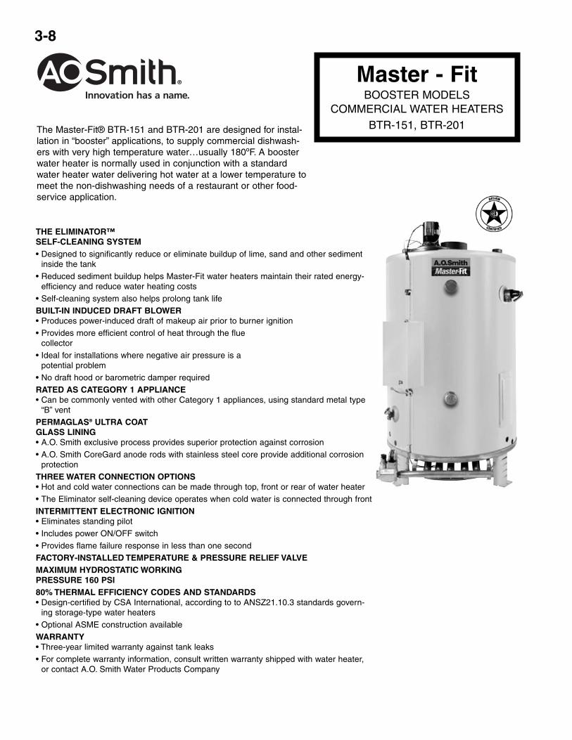
The Master-Fit® BTR-151 and BTR-201 are designed for instal-lation in “booster” applications, to supply commercial dishwash-ers with very high temperature water…usually 180ºF. A boosterwater heater is normally used in conjunction with a standardwater heater water delivering hot water at a lower temperature tomeet the non-dishwashing needs of a restaurant or other food-service application.
Master - FitBOOSTER MODELS
COMMERCIAL WATER HEATERSBTR-151, BTR-201

3-9
DIMENSIONS AND WEIGHT
BTU FIRSTINPUT HOUR RECOVERY – GALLONS
MODEL GALS. PER RATING PER HOUR AT °F TEMPERATURE RISENUMBER CAP. HOUR 100°F
RISE 40° 100° 140°
BTR-151 32 150,000 167 364 145 104
BTR-201 32 199,000 216 485 194 139
SUGGESTED SPECIFICATIONGas booster water heater(s) shall be A.O. Smith Master-Fit, Model Number ___________________ , with a 32-gallon storage capacity, an input rate of __________________ BTU/HR, _________________ gas, and a recoveryrate of ________ gallons per hour at a ________ degree Fahrenheit temperature rise, and a maximum hydrostaticworking pressure of 160 psi.
Unit(s) shall have a fan-assisted combustion system, providing a power-induced draft of makeup air prior to burnerignition.
Unit(s) shall be equipped with intermittent electronic ignition with power on/off switch, which shall provide flamefailure response in less than one second. The burner for the unit(s) shall be easily removable. Unit(s) shall beequipped with a factory-installed temperature and pressure relief valve, and a 2-3/4” x 3-3/4” tank inspection port.
The water heater tank shall be glasslined and protected against premature failure in the following ways:
1. Against electrolytic corrosion by multiple, factory-installed anode rods
2. Against failure due to overheating caused by the buildup of scale, film and other sediment by a self-cleaningdevice, positioned inside the tank so that it directs the flow of inlet water in such a way that microscopic particlesof precipitated solids shall be kept in suspension and exhausted from the water heater on that or successive hotwater draws.
Unit(s) shall meet or exceed ASHRAE/IESNA 90.1-1999, and be design certified by CSA International, according toANSZ21.10.3 standards governing storage-type water heaters.
CAPACITY, INPUT AND OUTPUT
DIMENSIONS IN INCHES APPROX.MODEL GAS WATER SHIPPING
NUMBER CONN. CONN. WEIGHTA B C D E F G H (LBS.)
BTR-151 45 40 27-3/4 32-1/4 15-3/4 5 6-1/2" 6" 3/4" 1-1/2" 400
BTR-201 45 40 27-3/4 32-1/4 15-3/4 5 6-1/2" 6" 3/4" 1-1/2" 400
Master - FitBOOSTER MODELS
COMMERCIAL WATER HEATERSBTR-151, BTR-201

3-10
FEATURES80+ % thermal efficiency affords lower operating costs on most models.
WATER CONNECTIONS — For ease of installation, BTR’s feature on most models waterconnections on the top, front, and rear.
GLASS LINED TANK — Permaglas® Ultracoat is the proprietary ceramic coating developedby A.O. Smith’s ceramic engineers specifically for this heater. It is applied after the completetank has been assembled to give a seamless barrier against corrosion by hot water. Themaximum working pressure is 160 psi.
FULLY AUTOMATIC CONTROLS WITH SAFETY SHUTOFF — Accurate, dependable con-trol system. Manual reset gas shutoff device for added safety. Maximum inlet gas pressure is14" W.C. Minimum gas pressure is 4.5" W.C. natural gas, 11" W.C. propane.
FOAM INSULATION — Saves fuel, helps reduce standby heat loss.
JACKET — Heavy gauge steel finished with a baked enamel finish over a bonderized under-coat.
EASY CLEANING — Handhole cleanout allows easy cleaning.
FULLY TESTED FOR SAFETY AND PERFORMANCE — Design certified by theUnderwriters Laboratory for 180ºF hot water service. Meets rigid requirements of the NationalSanitation Foundation when equipped with optional leg kit. Certified for use on combustibleflooring.
INTERMITTENT IGNITION DEVICE — Eliminates standing pilot. Provides flame failureresponse in less than one second. Power ON/OFF switch.
EASY TO INSTALL — Completely factory-assembled. Only gas, water, vent and electric con-nections need be made. Provided with drain valve.
FACTORY INSTALLED AND TESTED DRAFT DIVERTER — Low profile “snap action”diverter with automatic motorized flue damper to minimize standby losses.
ANODES — CoreGuardTM long-life, stainless steel core anode rods.
PLUG KITS — Pipe nipples and caps are included to plug unused water connections.
OTHER FEATURES
• Equipped with gas pressure regulator and pilot filter
• Integral automatic gas shutoff system prevents excessive water temperature
• A.G A. rated temperature and pressure relief valve factory-installed
• Maximum working pressure is 160 psi standard
• Cathodic protection
• Adjustable thermostat witha 120-180ºF range.
OPTIONS
• Power vent kits for side wall venting.
• Manifold kits for multiple heater installations.
• Meets NSF Standard 5 with optional leg kit.
Dimension Tables for BTRModels 120-500
Approx Approx.Tank Input Ship Wt.Cap. Type of Rating
Model (Gals.) Gas Btu/Hr A B C D E F G H I J Std ASMBTR120 71 nat/prop 120,000 69-3/4 4-1/4 59-1/2 50-7/8 19-5/8 19 1/2 51-7/8 5 27-3/4 400 ---BTR154 81 nat/prop 154,000 73 4-1/4 66-1/2 57-7/8 19-5/8 19 1/2 59 6 27-3/4 470 ---BTR180 81 nat/prop 180,000 67-1/2 4-1/2 62 53-5/8 20-1/2 21 1/2 54-5/8 6 27-3/4 470 ---BTR197 100 nat/prop 199,000 75 4-1/2 70 61-5/8 20-1/2 21 1/2 62-5/8 6 27-3/4 603 ---BTR198 100 nat/prop 199,000 75 4-1/2 70 61-5/8 20-1/2 21 1/2 61-1/2 6 27-3/4 603 ---BTR199 81 nat/prop 190,000 67-1/2 4-1/2 62 53-5/8 20-1/2 21 1/2 53-1/2 6 27-3/4 470 ---BTR200(A) 100 nat/prop 199,000 72 4-1/2 65 55-7/8 19-3/4 23 1/2 54-7/8 6 30-1/4 630 724BTR250(A) 100 nat/prop 250,000 72 4-1/2 65 55-7/8 19-3/4 23 1/2 56-3/8 8 30-1/4 630 724BTR251(A) 65 nat/prop 251,000 75 4-1/2 65-3/4 57-1/4 20 NA 1/2 58-3/4 8 27-3/4 750 862BTR275(A)* 100 nat/prop 275,000 72 4-1/2 65 55-7/8 19-3/4 23 1/2 56-3/8 8 30-1/4 630 724BTR305(A) 65 nat/prop 305,000 75 4-1/2 65-3/4 57-1/4 20 NA 3/4 58-3/4 8 27-3/4 750 862BTR365(A) 85 nat/prop 365,000 79-1/2 4-1/2 70-1/4 62-1/2 22-1/2 21 3/4 63 8 27-3/4 725 833BTR400(A) 100 nat/prop 399,000 75-1/2 4-1/2 67-1/2 58-1/4 26-3/4 23 3/4 59 8 30-1/4 760 874BTR500(A) 85 nat/prop 500,000 82-1/4 4-1/2 73-1/2 65-1/4 25-1/2 21 1 65-3/4 8 27-3/4 745 856
MasterFit®
COMMERCIAL GAS TANK-TYPE WATERHEATERS BTR 120-500(A)
LIMITED WARRANTY OUTLINE
If the tank should leak any time during the first three years, under the terms of the limit-ed warranty, A. 0. Smith will furnish a replacement heater; installation, labor, handling andlocal delivery extra. THIS OUTLINE IS NOT A WARRANTY. For complete information,consult the written warranty or A. 0. Smith Water Products Company.
Warranty does not apply to product installed outside of the United States of Amenca orits territorial possessions andCanada.
ROUGH-IN DIMENSIONSSIDE VIEW OF BTR
Models 120-500
Gas Pressure RequirementsNatural Gas PropaneGas
Max. Supply Pressure 13.8" w.c. 13.8" w.c.Min. Supply Pressure 4.5" w.c. 11" w.c.Manifold Pressure 3.5" w.c. 10" w.c.
Electrical SpecificationsVolts Amps
BTR 120VAC .7BTR with Power Venter 120VAC 3.0 FLA

3-11
MasterFit®
COMMERCIAL GAS TANK-TYPE WATERHEATERS BTR 120-500(A)
RECOVERY CAPACITIES FOR BTRInput Temperature Rise - Degrees F - Gallons Per Hour
RatingModel Btu/Hr. Gal. 30 40 50 60 70 80 90 100 110 120 130 140BTR120 120,000 71 388 291 233 194 166 145 129 116 106 97 90 83BTR154 154,000 81 498 373 299 249 213 187 166 149 136 124 115 107BTR180 180,000 81 532 436 349 291 249 218 194 175 159 145 134 124BTR197 199,000 100 643 482 386 322 276 241 214 193 175 161 148 132BTR198 199,000 100 643 482 386 322 276 241 214 193 175 161 148 138BTR199 190,000 81 614 461 368 307 263 230 205 184 167 154 142 132BTR200(A) 199,000 100 643 482 386 322 276 241 214 193 175 161 148 132BTR250(A) 250,000 100 808 606 485 404 346 303 269 242 220 202 186 173BTR251(A) 251,000 65 811 608 487 406 348 304 270 243 221 203 187 174BTR275(A) 275,000 100 889 667 533 444 381 333 296 267 242 222 205 190BTR305(A) 305,000 65 986 739 592 493 423 370 329 296 269 246 228 211BTR365(A) 365,000 85 1180 885 708 590 506 442 393 354 322 295 272 253BTR400(A) 399,000 100 1293 970 776 646 554 485 431 388 353 323 298 277BTR500(A) 500,000 85 1616 1212 970 808 693 606 539 485 441 404 373 346
POWER VENTS FOR BTRFEATURESDESIGNED FOR FLEXIBILITY — Easy to install sidewall power vent system. Use these kits where gas is the preferred choice, but conventionalventing is costly. Allows conversion from electric to gas or upgrading to units with higher inputs without having to do costly venting system upgrades.Easy to install and wire. Approved for use on all A.O. Smith water heaters listed below. Allows th~ use of smaller diameter vent pipe than allowedwith conventional venting.
POWERFUL 115 VOLT POWER VENTER — Allows venting up to 100 equivalent feet away. Each model sized for a perfect match with A.O. Smithwater heaters. Power Venters have one or more of the following depending on the heater’s requirements. Built in 24/11 Svolt relay to interface withcontrol systems. Combination 24 volt relay and adjustable post-purge timer control in lieu of relay on some models. Installed diaphragm draft prov-ing switch. Vibration isolation mount works with common plumber’s strap and helps keep operation quiet. All controls factory mounted and wired forsimple installation.
ALUMINUM VENT HOOD — Mounts on outside of wall. Features telescoping vent pipe connection sleeve, rust free construction, outside wall con-densate shield, 1 airspace provides clearance forcombustibles, special heat shield protects building exterior. Mounting hardware included.
COLOR CODED WIRING HARNESS — Eliminates need for electrician (check codes). Simple 24 volt connections and a 25’ lowvoltage cable.Includes grounded 115 volt power cord with plug on models up through 250,000 btu.
ADAPTER FITTINGS — Provided along with mounting hardware and instructions for a quick and simple installation. Approved vent pipe reducerssupplied where applicable.
APPROVED FOR TYPE-B VENT — Non pressurized vent from heater to power venter allows the use of economical Type-B vent pipe.
C D E FBTR Max. Vent Vent Vent Vent Vent
Water Part Motor Motor Length Dia. Assembly Assembly Assembly Termination G H RoughModels Number Watts Amps of Vent Size Height Depth Width Square Dia. In
120 6543 95 1.26 100 ft.* 4" 7-7/8" 7" 10-1/4" 9" 9-1/2" 6-5/8" 7-1/8"
154-251 6544 95 1.26 100 ft.* 4" 7-7/8" 7" 10-1/4" 9" 9-1/2" 6-5/8" 7-1/8"
275-500 6545 224 2.0 100 ft.* 6" 9-1/4" 8-1/2" 11-1/2" 10-1/8" 9-1/2" 8-1/2" 9"
*Vent pipe/vent hood connection based on Class B vent pipe sizes. Calculated using total pipe length, plus 5 ft. for every 90" elbow and 2-1/2 ft. or every 45" elbow.
Clearance to Clearance toCombustibles Non-Combustibles
Model Sides & Rear Top Cover Sides & Rear Top CoverBTR120 1" 12" 0" 12"BTR154 1" 12" 0" 12"BTR180 1" 12" 0" 12"BTR197 1" 12" 0" 12"BTR198 1" 12" 0" 12"BTR199 1" 12" 0" 12"BTR200(A) 1" 12" 0" 12"BTR250(A) 2" 12" 0" 12"BTR251(A) 2" 12" 0" 12"BTR275(A) 2" 12" 0" 12"BTR305(A) 2" 12" 0" 12"BTR365(A) 3" 12" 0" 12"BTR400(A) 3" 12" 0" 12"BTR500(A) 6" 12" 3" 12"
Water Connections in InchesInlet Outlet
Models Top Front Back Top Front BackBTR120 1-1/2 1-1/2 1-1/2 1-1/2 1-1/2 1-1/2BTR154 1-1/2 1-1/2 1-1/2 1-1/2 1-1/2 1-1/2BTR180 1-1/2 1-1/2 1-1/2 1-1/2 1-1/2 1-1/2BTR197 1-1/2 1-1/2 1-1/2 1-1/2 1-1/2 1-1/2BTR198 1-1/2 1-1/2 2 1-1/2 1-1/2 2BTR199 1-1/2 1-1/2 1-1/2 1-1/2 1-1/2 1-1/2BTR200(A) 1-1/2 2 2 1-1/2 2 2BTR250(A) 1-1/2 2 2 1-1/2 2 2BTR251(A) NA 1-1/2 1-1/2 NA 1-1/2 1-1/2BTR275(A) 1-1/2 2 2 1-1/2 2 2BTR305(A) NA 1-1/2 1-1/2 NA 1-1/2 1-1/2BTR365(A) 1-1/2 1-1/2 1-1/2 1-1/2 1-1/2 1-1/2BTR400(A) 1-1/2 2 2 1-1/2 2 2BTR500(A) 1-1/2 1-1/2 1-1/2 1-1/2 1-1/2 1-1/2
3-12
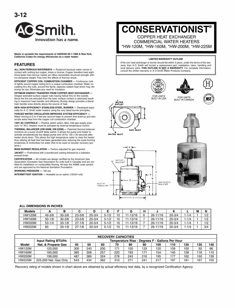
CONSERVATIONIST®
COPPER HEAT EXCHANGERCOMMERCIAL WATER HEATERS
*HW-120M, *HW-160M, *HW-200M, *HW-225M
Meets or exceeds the requirements of ASHRAE-90.1-1989 & New York,California Codes for energy efficiencies as a water heater.
FEATURESALL NON-FERROUS WATERWAYS — Rustproof because water comes incontact with nothing but copper, brass or bronze. Copper transfers heat eighttimes faster than ferrous metals yet offers remarkable structural strength with-out excessive weight. Free from the effects of therma! shock.
EFFICIENT COPPER COIL COMBUSTION CHAMBER — Continuous coilsof tightly wound copper tubing form a unique combustion chamber. Water cir-culating thru the coils, around the flame, captures radiant heat which may oth-erwise be lost. Eliminates any need for insulation.
OPTIMUM ENERGY TRANSFER FROM COPPER HEAT EXCHANGER —Integral extended surface copper tube having helical fins on the outside.Since the fins are extruded from the tube, surface contact is optimized result-ing in maximum heat transfer and efficiency. Burkay design provides a liberalheat transfer area directly above the source of heat.
NEW HIGH-EFFICIENCY STAINLESS-STEEL BURNER — Developed espe-cially for A. O. Smith water heaters using the very latest burner principles.
FORCED WATER CIRCULATION IMPROVES SYSTEM EFFICIENCY —Water moving at 2 to 4 feet per second helps to prevent lime build-up and alsoscrubs extra heat from the copper coil combustion chamber.
120V AC CONTROLS — Positive switch action. Max. inlet gas supply pres-sure 14" W.C. Heaters must be activated by external temperature control.
THERMAL BALANCER (HW-200M, HW-225M) — Patented thermal balancerfunctions as a pump shutoff delay switch. It allows the pump and heater toactivate simultaneously but delays pump shut off for 120 ± 30 seconds afterheater shuts down. This allows the high temperature water to clear the heaterthus utilizing all heat that had been generated plus reducing the scale formingtendencies of motionless hot water (Not to be used on booster recovery sys-tems.)
MAIN BURNER REGULATION — Factory adjusted for gas required.
JACKET — Prefinished with a bonderized coating followed by a bakedonenamel finish.
CERTIFICATION — All models are design certified by the American GasAssociation (Canadian Gas Association for units built in Canada) and are cer-tified for installation on combustible flooring. All bear the ASME code symboland are approved by the National Sanitation Foundation.
WORKING PRESSURE — 160 psi.
INTERMITTENT IGNITION — Available as an option (120/24 volt).
LIMITED WARRANTY OUTLINE
If the coil, heat exchanger or burner should fail within 5 years, under the terms of the war-ranty, then A.O. Smith will furnish a replacement part; installation, labor, handling andlocal delivery extra. THIS OUTLINE IS NOT A WARRANTY. For complete information,consult the written warranty or A O Smith Water Products Company.
FOR UNITSBUILT IN USA FOR UNITS
BUILT IN CANADA
Models A B C D E F G H J K L M NHW120M 49-3/8 30-3/8 23-5/8 20-3/4 5-1/2 10 11-13/16 6 26-11/16 20-3/4 1-1/4 1 1/2HW160M 50-1/8 30-3/8 23-5/8 20-3/4 5-1/2 10 11-13/16 7 26-11/16 20-3/4 1-1/4 1 1/2HW200M 53-1/4 33-1/8 27-1/8 20-3/4 5-1/2 10 11-13/16 7 26-11/16 20-3/4 1-1/4 1 1/2HW225M 60 33-1/8 27-1/8 20-3/4 5-1/2 10 11-13/16 7 26-11/16 20-3/4 1-1/4 1 3/4
ALL DIMENSIONS IN INCHES
Recovery rating of models shown in chart above are obtained by actual efficiency test data, by a recognized Certification Agency.
RECOVERY CAPACITIESInput Rating BTU/Hr. Temperature Rise - Degrees F - Gallons Per Hour
Model Nat. & Propane Gas 40 50 60 70 80 90 100 110 120 130 140HW120M 120,000 300 240 200 171 150 133 120 109 100 92 86HW160M 160,000 385 308 257 220 193 171 154 140 128 118 110HW200M 199,000 487 389 324 278 243 216 195 177 162 150 139HW225M 225,000 Nat. Gas Only 543 434 362 310 271 241 217 197 181 167 155

3-13
CONSERVATIONIST®
COMMERCIAL BOILERSHW-300 THRU HW-670
Domestic Hot Water Supply Boiler
Meets or exceeds the requirements of ASHRAE 90.1b-1992,New York and California Energy Codes.
FEATURESALL NON-FERROUS WATERWAYS — All castings are made of Bronze or Brass. All watertubes are made from copper. Brazed joints or flare union construction make the heater immuneto the effects of thermal shock and thermal cycling. A great boiler for domestic hot water supplysystems.
EFFICIENT COPPER COIL COMBUSTION CHAMBER — The combustion chamber is a heatexchanger formed from a two passage coil of tightly wound continuous copper tube. Water circu-lating through this coil surrounds the main burner and captures the radiant heat. A wrap of insu-lation on the outside of the coil retains the heat captured by the circulating water.
COPPER HEAT EXCHANGER — Directly above the coil and the main burner is a compact, hor-izontal, copper fin tube heat exchanger. The flue gases must pass through this efficient heatexchanger before leaving the boiler. This unique Burkay coil and heat exchanger design providemaximum heat transfer and proven field durability.
BURKAY BURNER MAXIMIZES EFFICIENCY — The patented Burkay burner uses primary airinjection at up to 72 individual orifices plus secondary entrainment of air. Approved for installationon combustible floors as shipped from factory.
GAS VALVES — Slow opening redundant gas valves ensure smooth light-off without flame roll-out or pilot outage.
THERMAL BALANCER — Patented pump delay system that allows boiler and pump to runsimultaneously but delays pump shut off at end of heating cycle to remove usable heat from theheat exchanger and reduce the scale forming tendencies of motionless hot water.
AUTOMATIC SAFETY CONTROLS AND ELECTRONIC IGNITION — Proven pilot ignition sys-tem provides flame failure response in under one (1) second. Redundant high limit controls andgas valves assure safe shutoff in the event of overheating or flame failure. Requires 120V 60Hz,maximum inlet gas pressure of 14" WC and activation of heater by external temperature control.
OPTIONAL POWERED VENT HOOD — for sidewall venting.
WORKING PRESSURE — ASME approved, hydrostatically tested and certified for 160 psi.
*Except model HW-399 is 81%.
Not approved for instantaneous applications.
HW – INDOORINSTALLATION ONLY
HW MODELSCERTIFICATION & APPROVAL
LIMITED WARRANTY OUTLINE
If the heat exchanger modules should fail within 5 years, under the terms of the war-ranty; A. O. Smith will furnish a replacement part; installation, labor, handling and localdelivery extra. THIS OUTLINE IS NOT A WARRANTY. For complete information, con-sult the written warranty or A. O. Smith Water Products Company.
USA CANADA
Input RatingA.G.A. BTUH Temperature Rise - Degrees FNatural and
Model Propane Gases 20 30 40 50 60 70 80 90 100 110 120 130 140HW-300 300,000 GPH 1491 993.9 745 596 497 426 373 331 298 271 248 229 213
GPM 24.8 16.6 12.4 9.9 8.3 7.1 6.2 5.5 4.9 4.5 4.1 3.8 3.5HW-420 420,000 GPH 2087 1391 1044 935 696 596 521.9 464 417 379 348 321 298
GPM 34.7 23.2 17.4 13.9 11.6 9.9 8.7 7.7 6.9 6.3 5.8 5.3 4.9HW-520 520,000 GPH 2584 1723 1292 1034 861 738 646 574 516 470 430 396 369
GPM 43 28.7 21.5 17.2 14.4 12.3 10.8 9.6 8.6 7.8 7.1 6.6 6.1660,000 Nat. GPH 3280 2186 1640 1312 1093 937 820 729 656 596 547 504 468
HW-670 GPM 54.6 36.4 27.3 21.9 18.2 15.6 13.6 12.1 10.9 9.9 9.1 8.4 7.8670,000 LP GPH 3249 2166 1624 1299 1083 928 812 722 650 591 541 500 464
GPM 54.1 36.1 27.1 21.7 18.1 15.5 13.5 12.0 10.8 9.8 9.0 8.3 7.7
NOTE: MANIFOLD HAS EXTRA OPENINGS FORTHERMOMETER (3/4" AND RELIEF VALVE [1"](HW-520 AND -670 ONLY)
DIMENSIONS
ApproxShip. Wt.
Models A B C D E F G H J K L M N P Q R S V Lbs.HW-300 65 43-1/4 25-1/4 29-5/8 16-1/2 8 12 36 9 1-1/4 1-1/4 3/4 26-5/8 14 1 10-1/8 5-318 5 240HW-420 57-1/8 45-1/8 27 31-1/2 16-3/4 10 12 38-3/4 9 1-1/2 1-1/2 1 27-1/2 14 1 11-1/4 5-1/2 5 291HW-520 68-5/16 56-1/4 27 36-1/2 18 10 12 46-1/2 9 2 2 1-1/4 24-1/2 11 3-1/2 12 5-3/4 7 361HW-670 67 56-1/4 27 38-1/4 17-3/4 12 12 46-1/2 9 2 2 1-1/4 26-3/4 13-1/4 3-1/2 12 5-3/4 7 361
SPECIFICATIONS AND RECOVERY CAPACITIES
Note: When used as a hot water boiler, heat exchanger carries a 10 year warranty.
3-14
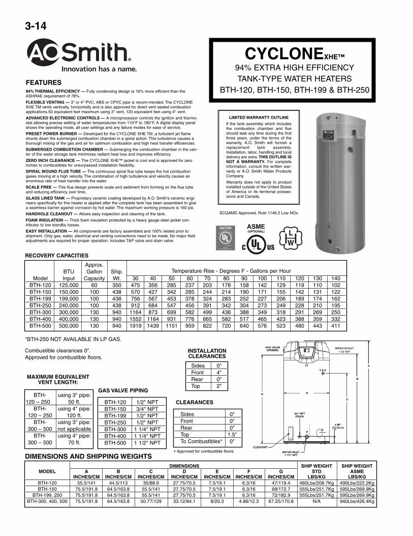
CYCLONEXHE™
94% EXTRA HIGH EFFICIENCYTANK-TYPE WATER HEATERS
BTH-120, BTH-150, BTH-199 & BTH-250
SCQAMD Approved, Rule 1146.2 Low NOx
LIMITED WARRANTY OUTLINE
If the tank assembly which includesthe combustion chamber and flueshould leak any time during the firstthree years, under the terms of thewarranty, A.O. Smith will furnish areplacement tank assembly.Installation, labor, handling and localdelivery are extra. THIS OUTLINE ISNOT A WARRANTY. For completeinformation, consult the written war-ranty or A.O. Smith Water ProductsCompany.
Warranty does not apply to productinstalled outside of the United Statesof America or its territorial posses-sions and Canada.
INSTALLATIONCLEARANCES
Sides 0"Front 4"Rear 0"Top 2"
Combustible clearances 0".Approved for combustible floors.
DIMENSIONS SHIP WEIGHT SHIP WEIGHTMODEL A B C D E F G STD ASME
INCHES/CM INCHES/CM INCHES/CM INCHES/CM INCHES/CM INCHES/CM INCHES/CM LBS/KG LBS/KGBTH-120 55.5/141 44.5/113 35/88.9 27.75/70.5 7.5/19.1 6.3/16 47/119.4 460Lbs/208.7Kg 490Lbs/222.2KgBTH-150 75.5/191.8 64.5/163.8 55.5/141 27.75/70.5 7.5/19.1 6.3/16 68/172.7 555Lbs/251.7Kg 595Lbs/269.9Kg
BTH-199, 250 75.5/191.8 64.5/163.8 55.5/141 27.75/70.5 7.5/19.1 6.3/16 72/182.9 555Lbs/251.7Kg 595Lbs/269.9KgBTH-300, 400, 500 75.5/191.8 64.5/163.8 50.77/129 33.12/84.1 8/20.3 4.86/12.3 67.25/170.8 N/A 940Lbs/426.4Kg
DIMENSIONS AND SHIPPING WEIGHTS
Sides 0"Front 0"Rear 0"Top 1.5"To Combustibles* 0"
CLEARANCES
• Approved for combustible floors
BTH-120 1/2" NPTBTH-150 3/4" NPTBTH-199 1/2" NPTBTH-250 1/2" NPTBTH-300 1 1/4" NPTBTH-400 1 1/4" NPTBTH-500 1 1/2" NPT
GAS VALVE PIPINGBTH- using 3" pipe:
120 – 250 50 ft.BTH- using 4" pipe:
120 – 250 120 ft.BTH- using 3" pipe:
300 – 500 not applicableBTH- using 4" pipe:
300 – 500 70 ft.
MAXIMUM EQUIVALENTVENT LENGTH:
Approx.BTU Gallon Ship. Temperature Rise - Degrees F - Gallons per Hour
Model Input Capacity Wt. 30 40 50 60 70 80 90 100 110 120 130 140BTH-120 125,000 60 350 475 356 285 237 203 178 158 142 129 119 110 102BTH-150 150,000 100 438 570 427 342 285 244 214 190 171 155 142 131 122BTH-199 199,000 100 438 756 567 453 378 324 283 252 227 206 189 174 162BTH-250 240,000 100 438 912 684 547 456 391 342 304 273 249 228 210 195BTH-300 300,000 130 940 1164 873 699 582 499 436 388 349 318 291 269 250BTH-400 400,000 130 940 1552 1164 931 776 665 582 517 465 423 388 359 332BTH-500 500,000 130 940 1919 1439 1151 959 822 720 640 576 523 480 443 411
RECOVERY CAPACITIES
*BTH-250 NOT AVAILABLE IN LP GAS.
FEATURES94% THERMAL EFFICIENCY — Fully condensing design is 16% more efficient than theASHRAE requirement of 78%.
FLEXIBLE VENTING — 3" or 4" PVC, ABS or CPVC pipe is recom-mended. The CYCLONEXHE TM vents vertically, horizontally and is also approved for direct vent sealed combustionapplications.50 equivalent feet maximum using 3" vent, 120 equivalent feet using 4" vent.
ADVANCED ELECTRONIC CONTROLS — A microprocessor controls the ignition and thermo-stat allowing precise setting of water temperatures from 110°F to 180°F. A digital display panelshows the operating mode, all user settings and any failure modes for ease of service.
PRESET POWER BURNER — Developed for the CYCLONE XHE TM ,a turbulent jet flameshoots down the submerged combustion chamber in a spiral action. This turbulence causes athorough mixing of the gas and air for optimum combustion and high heat transfer efficiencies.
SUBMERGED COMBUSTION CHAMBER — Submerging the combustion chamber in the cen-ter of the water storage tank minimizes radiant heat loss and improves efficiency.
ZERO INCH CLEARANCE — The CYCLONE XHE™ jacket is cool and is approved for zeroinches to combustibles for unsurpassed installation flexibility.
SPIRAL WOUND FLUE TUBE — The continuous spiral flue tube keeps the hot combustiongases moving at a high velocity. The combination of high turbulence and velocity causes anenormous rate of heat transfer into the water.
SCALE FREE — This flue design prevents scale and sediment from forming on the flue tubeand reducing efficiency over time.
GLASS LINED TANK — Proprietary ceramic coating developed by A.O. Smith's ceramic engi-neers specifically for this heater is applied after the complete tank has been assembled to givea seamless barrier against corrosion by hot water. The maximum working pressure is 160 psi.
HANDHOLE CLEANOUT — Allows easy inspection and cleaning of the tank.
FOAM INSULATION — Thick foam insulation protected by a heavy gauge steel jacket con-tributes to low standby losses.
EASY INSTALLATION — All components are factory assembled and 100% tested prior toshipment. Only gas, water, electrical and venting connections need to be made. No major fieldadjustments are required for proper operation. Includes T&P valve and drain valve.

3-15
ON DEMANDHIGH EFFICIENCY INDOOR
TANKLESS WATER HEATERSATI-520H-N, ATI-520H-PFEATURES
ENERGY STAR® QUALIFIED
Condensing Technology ProvidesSignificant Energy Cost Savings• Stronger than standard copper and
more resilient against erosion
Secondary Heat Exchanger Is MadeOf Type 316L Stainless Steel• Provides additional protection against
corrosion
Continuous Maximum Flow RatesUp To 9.0 GPM • Can Be Used In Both Residential
And Light Commercial Applications
Easily Connect Up To 4 Units• With no additional parts or acces-
sories needed
Built-in Display Shows OperatingTemperature Along With DiagnosticAnd Error Codes
SAFETY FEATURES• Air-Fuel Ratio (AFR) Sensor
• Exhaust & Water Temperature SafetyControl
• Overheat Cutoff Fuse
•Internal Freeze Protection System
POWER DIRECT VENT DESIGN• 4" Pipe Vents up to 50 Equivalent
Feet or 3" Pipe Vents up to 25Equivalent Feet
• Uses Inexpensive PVC, CPVC, ORABS Pipe for Intake and Exhaust(solid core only)
• Category III Stainless Steel ventingcan also be used
ACCESSORIES• Remote Temperature Controller
• Pipe Cover
• Neutralizer Kit
• Plumbing Installation Kits
• PVC Intake Adaptor
• Concentric Termination
WARRANTY• 12-year limited warranty on heat
exchanger in residential applications
• 5-year limited warranty on heatexchanger in commercial applications
• 5-year warranty on all parts
ANSI Z21.10.3 CSA 4.3
INDOOR CONDENSING MODELSGas Consumption Input Inlet Gas Pressure Dimensions in Inches Approx.
ShippingModel Fuel Minimum Maximum Minimum Maximum Energy Hot/Cold Weight
Number Type Btu/H Btu/H W.C. W.C. Factor Gas Conn. Height Width Diameter (LBS)
ATI-520H-N Natural 13,000 199,000 5.0 10.5 0.91 3/4” NPT 25.6 18.5 12.4 73
ATI-520H-P Propane 13,000 199,000 8.0 14.0 0.91 3/4” NPT 25.6 18.5 12.4 70

3-16
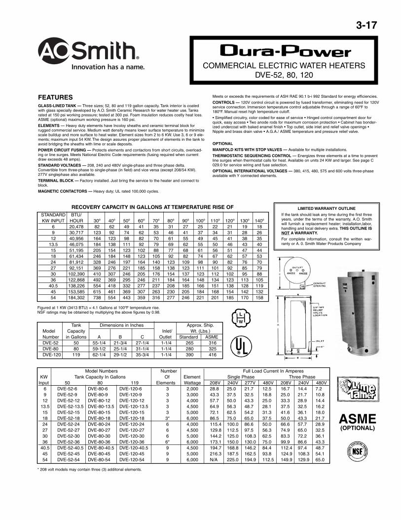
COMMERCIAL ELECTRIC WATER HEATERSDRE-52, 80, 120
FEATURESGLASS-LINED TANK — Three sizes: 50, 80 and 119 gallon capacity. Tank interior is coated with glass spe-cially developed by A.O. Smith Ceramic Research for water heater use. Tanks rated 150 psi working pressure(ASME 150 psi). Foam insulation reduces costly heat loss and is vermin proof.
ELEMENTS — Incoloy sheathing for longer life. Low watt density: means lower surface temperature to mini-mize scale buildup and more surface to heat water. Element sizes from 3 to 6 Kw. Use 3, 6, or 9 elementsstandard; total of 9 to 54 Kw input (see chart on back).
FUSING — Protects all elements, thermostats, and internal wiring circuits against excess current flow. MeetsNational Electric Code requirements that non-ASME tanks must have internal fusing when current drawexceeds 48 amps.
STANDARD VOLTAGES — 208, 240 and 480V single-phase and three phase delta. Convertible from three-phase to single-phase (in field) and vice versa. 277V single-phase also available.
TERMINAL BLOCK — Factory installed. Just bring the service to the heater and connect to block.
CONTROLS — One temperature control (adjustable through a range of 120º to 180ºF) and manual resethigh temperature cutoft per element. Thermostat step control may be achieved by varying settings on individ-ual temperature controls. Located behind hinged control compartment door for quick, easy access.
ASME
No. ofModel Numbers Elements Full Load Current In Amperes
KW Tank Capacity In Gallons and Element Single Phase Three Phaselnput 50 80 119 Thermostats Wattage 208V 240V 277V 480V 208V 240V 480V
9 DRE-52-9 DRE-80-9 DRE-120-9 3 3000 43.3 37.5 32.5 18.8 25.0 21.7 10.812 DRE-52-12 DRE-80-12 DRE-120-12 3 4000 57.7 50.0 43.3 25.0 33.3 28.9 14.415 DRE-52-15 DRE-80-15 DRE-120-15 3 5000 72.1 62.5 54.2 31.3 41.6 36.1 18.0
13.5 DRE-52-13.5 DRE-80-13.5 DRE-120-13.5 3 4500 64.9 56.3 48.7 28.1 37.5 32.5 16.218 DRE-52-18 DRE-80-18 DRE-120-18 3+ 6000 86.5 75.0 65.0 37.5 50.0 43.3 21.724 DRE-52-24 DRE-80-24 DRE-120-24 6 4000 115.4 100.0 86.6 50.0 66.6 57.7 28.927 DRE-52-27 DRE-80-27 DRE-120-27 6 4500 129.8 112.5 97.5 56.3 74.9 65.0 32.530 DRE-52-30 DRE-80-30 DRE-120-30 6 5000 144.2 125.0 108.3 62.5 83.3 72.2 36.136 DRE-52-36 DRE-80-36 DRE-120-36 6+ 6000 173.1 150.0 130.0 75.0 99.9 86.6 43.3
40.5 N/A DRE-80-40.5 DRE-120-40.5 9 4500 194.7 168.8 146.2 84.4 112.4 97.4 48.745 N/A DRE-80-45 DRE-120-45 9 5000 216.3 187.5 162.5 93.8 124.9 108.3 54.154 N/A DRE-80-54 DRE-120-54 9 6000 N/A 225.0 194.9 112.5 149.9 129.9 65.0
Figured at 1 KW (3413 Btu) = 4.1 Gallons at 100ºF temperature rise.To determine recovery rate per minute, divide recovery rate per hour by 60.NSF ratings may be obtained by multiplying the above GPH figures by 0.98.
STANDARD BTU/KW INPUT HOUR 30º 40º 50º 60º 70º 80º 90º 100º 110º 120º 130º 140º
9 30,717 123 92 74 62 53 46 41 37 34 31 28 2612 40,956 164 123 98 82 70 61 55 49 45 41 38 35
13.5 46,025 184 138 111 92 79 69 62 55 50 46 43 4015 51,195 205 154 123 102 88 77 68 61 56 51 47 4418 61,434 246 184 148 123 105 92 82 74 67 62 57 5324 81,912 328 246 197 164 140 123 109 98 90 82 76 7027 92,151 369 276 221 185 158 138 123 111 101 92 85 7930 102,390 410 307 246 205 176 154 137 123 112 102 95 8836 122,868 492 369 295 246 211 184 164 148 134 123 113 105
40.5 138,226 554 418 332 277 237 208 185 166 151 138 128 11945 153,585 615 461 369 307 263 230 205 184 168 154 142 13254 184,302 738 554 443 369 316 277 246 221 201 185 170 158
RECOVERY RATE IN GALLONS PER HOUR*Temperature Rise ºF
Tank Dimensions in Inches Approx. Ship.Model Capacity Inlet/ Wt. (Lbs.)Number in Gallons A B C Outlet Standard ASMEDRE-52 50 55-1/4 21-3/4 27-1/4 1-1/4 245 296DRE-80 80 59-1/2 25-1/4 31-1/4 1-1/4 264 309DRE-120 119 62-1/4 29-1/2 35-3/4 1-1/4 375 401
+ 208 volt models may contain three (3) additonal elements and thermostats.
OTHER STANDARD FEATURES
• Simplified circuitry, color coded forease of service
• Two anode rods for maximum corro-sion protection
• Cabinet has bonderized undercoatwith baked enamel finish
• Bottom inlet and top outlet openings
• Drain valve
• A.G.A./A.S.M.E. Temperature andPressure relief valve
• Single panel control box
OPTIONAL
• U.L. listed conversion kits to correctsome voltage and Kw requirements inthe field before and after installation.
• Manifold kits with gate valves - avail-able for multiple installation.
• ASME 150 psi tank construction
• International voltages — 380, 415and 480 volts, three-phase availablewith Y connected elements.
• Field conversion kits for voltage andKw.
LIMITED WARRANTY OUTLINE
If the tank should leak any time during the first three years, under the termsof the warranty, A.O. Smith will furnish a replacement heater; installation,labor, handling and local delivery extra.
THIS OUTLINE IS NOT A WARRANTY.
For complete information, consult the written warranty or A.O. Smith WaterProducts Company.
3-17
FEATURESGLASS-LINED TANK — Three sizes; 52, 80 and 119 gallon capacity. Tank interior is coatedwith glass specially developed by A.O. Smith Ceramic Research for water heater use. Tanksrated at 150 psi working pressure; tested at 300 psi. Foam insulation reduces costly heat loss.ASME (optional) maximum working pressure is 160 psi.
ELEMENTS — Heavy duty elements have Incoloy sheaths and ceramic terminal block forrugged commercial service. Medium watt density means lower surface temperature to minimizescale buildup and more surface to heat water. Element sizes from 2 to 6 KW. Use 3, 6 or 9 ele-ments; maximum input 54 KW. The design assures proper placement of elements in the tank toavoid bridging the sheaths with lime or scale deposits.
POWER CIRCUIT FUSING — Protects elements and contactors from short circuits, overload-ing or line surges. Meets National Electric Code requirements (fusing required when currentdraw exceeds 48 amps).
STANDARD VOLTAGES — 208, 240 and 480V single-phase and three phase delta.Convertible from three-phase to single-phase (in field) and vice versa (except 208/54 KW).277V singlephase also available.
TERMINAL BLOCK — Factory installed. Just bring the service to the heater and connect toblock.
MAGNETIC CONTACTORS — Heavy duty; UL rated 100,000 cycles.
Meets or exceeds the requirements of ASH RAE 90.1 b-i 992 Standard for energy efficiencies.
CONTROLS — 120V control circuit is powered by fused transformer, eliminating need for 120Vservice connection. Immersion temperature control adjustable through a range of 60ºF to180ºF. Manual reset high temperature cutoff.
• Simplified circuitry, color coded for ease of service • Hinged control compartment door forquick, easy access • Two anode rods for maximum corrosion protection • Cabinet has bonder-ized undercoat with baked enamel finish • Top outlet, side inlet and relief valve openings •Nipple and brass drain valve • A.G.A./ ASME temperature and pressure relief valve.
OPTIONAL
MANIFOLD KITS WITH STOP VALVES — Available for multiple installations.
THERMOSTATIC SEQUENCING CONTROL — Energizes three elements at a time to preventline surges when thermostat calls for heat. Available on units 24 KW and larger. See page C029.0 for service wiring and fuse selection.
OPTIONAL INTERNATIONAL VOLTAGES — 380, 415, 480, 575 and 600 volts three-phaseavailable with Y connected elements.
LIMITED WARRANTY OUTLINE
If the tank should leak any time during the first threeyears, under the terms of the warranty, A.O. Smithwill furnish a replacement heater; installation,labor,handling and local delivery extra. THIS OUTLINE ISNOT A WARRANTY.
For complete information, consult the written war-ranty or A. 0. Smith Water Products Company
COMMERCIAL ELECTRIC WATER HEATERSDVE-52, 80, 120
ASME(OPTIONAL)
Figured at 1 KW (3413 BTU) = 4.1 Gallons at 100ºF temperature rise.NSF ratings may be obtained by multiplying the above figures by 0.98.
STANDARD BTU/KW INPUT HOUR 30º 40º 50º 60º 70º 80º 90º 100º 110º 120º 130º 140º
6 20,478 82 62 49 41 35 31 27 25 22 21 19 189 30,717 123 92 74 62 53 46 41 37 34 31 28 2612 40,956 164 123 98 82 70 61 55 49 45 41 38 35
13.5 46,075 184 138 111 92 79 69 62 55 50 46 43 4015 51,195 205 154 123 102 88 77 68 61 56 51 47 4418 61,434 246 184 148 123 105 92 82 74 67 62 57 5324 81,912 328 246 197 164 140 123 109 98 90 82 76 7027 92,151 369 276 221 185 158 138 123 111 101 92 85 7930 102,390 410 307 246 205 176 154 137 123 112 102 95 8836 122,868 492 369 295 246 211 184 164 148 134 123 113 105
40.5 138,226 554 418 332 277 237 208 185 166 151 138 128 11945 153,585 615 461 369 307 263 230 205 184 168 154 142 13254 184,302 738 554 443 359 316 277 246 221 201 185 170 158
RECOVERY CAPACITY IN GALLONS AT TEMPERATURE RISE OF
Tank Dimensions in Inches Approx. Ship.Model Capacity Inlet/ Wt. (Lbs.)Number in Gallons A B C Outlet Standard ASMEDVE-52 50 55-1/4 21-3/4 27-1/4 1-1/4 265 316DVE-80 80 59-1/2 25-1/4 31-1/4 1-1/4 280 325DVE-120 119 62-1/4 29-1/2 35-3/4 1-1/4 390 416
Model Numbers Number Full Load Current In AmperesKW Tank Capacity In Gallons Of Element Single Phase Three Phase
lnput 50 80 119 Elements Wattage 208V 240V 277V 480V 208V 240V 480V6 DVE-52-6 DVE-80-6 DVE-120-6 3 2,000 28.8 25.0 21.7 12.5 16.7 14.4 7.29 DVE-52-9 DVE-80-9 DVE-120-9 3 3,000 43.3 37.5 32.5 18.8 25.0 21.7 10.812 DVE-52-12 DVE-80-12 DVE-120-12 3 4,000 57.7 50.0 43.3 25.0 33.3 28.9 14.4
13.5 DVE-52-13.5 DVE-80-13.5 DVE-120-13.5 3 4,500 64.9 56.3 48.7 28.1 37.5 32.5 16.215 DVE-52-15 DVE-80-15 DVE-120-15 3 5,000 72.1 62.5 54.2 31.3 41.6 36.1 18.018 DVE-52-18 DVE-80-18 DVE-120-18 3* 6,000 86.5 75.0 65.0 37.5 50.0 43.3 21.724 DVE-52-24 DVE-80-24 DVE-120-24 6 4,000 115.4 100.0 86.6 50.0 66.6 57.7 28.927 DVE-52-27 DVE-80-27 DVE-120-27 6 4,500 129.8 112.5 97.5 56.3 74.9 65.0 32.530 DVE-52-30 DVE-80-30 DVE-120-30 6 5,000 144.2 125.0 108.3 62.5 83.3 72.2 36.136 DVE-52-36 DVE-80-36 DVE-120-36 6* 6,000 173.1 150.0 130.0 75.0 99.9 86.6 43.3
40.5 DVE-52-40.5 DVE-80-40.5 DVE-120-40.5 9 4,500 194.7 168.8 146.2 84.4 112.4 97.4 48.745 DVE-52-45 DVE-80-45 DVE-120-45 9 5,000 216.3 187.5 162.5 93.8 124.9 108.3 54.154 DVE-52-54 DVE-80-54 DVE-120-54 9 6,000 N/A 225.0 194.9 112.5 149.9 129.9 65.0
* 208 volt models may contain three (3) additonal elements.

3-18
COMMERCIALHOT WATER STORAGE TANKS
TJV-120M, TJV120A
FEATURESExceeds ASHRAE 90.1b-1992.
A.O. Smith storage tanks are ideal for use with gas-fired copper heat exchanger equipment forstorage of any potable water at temperatures up to 180ºF.
GLASS-LINED TANK — Alkaline borosilicate composition permanently fused to steel by firingat a temperature of 1600ºF, providing years of corrosion protection and dependable use.
HEAVY GAUGE STEEL JACKET — With baked enamel finish.
THREADED OPENINGS — All tanks furnished with threaded openings for thermometer, reliefvalve, 2" recirculation lines, tankstat, and drain valve.
TJV-120M and TJV-120A
• Fits through 30" door • Magnesium anode • for anticorrosion protection
TJV-120M • 119 gallons • exceeds ASHRAE requirements • 150 psi working pressure.
OPTIONS
Perfectly balanced manifold kits (120 gallon models) allow installation where 240 to 480 gal-lons of stored water is required.
120 GALLON MODEL
LIMITED WARRANTY OUTLINE
If the tank should leak any time during the first 5 years, under the terms of the warranty,A.O. Smith will repair or replace the tank; installation, labor, handling and local deliveryextra. THIS OUTLINE IS NOT A WARRANTY. For complete information, consult the writ-ten warranty or A.O. Smith Water Products Company.

3-19
LARGE VOLUMEHOT WATER STORAGE TANKS
FEATURESA.O. Smith storage tanks are ideal for use with gas4i red copper heat exchangerequipment and other A. 0. Smith hot water systems for storage of any potable waterat temperatures as high as 180 degrees or lower.
GLASS-LINED — All internal surfaces exposed to water are glass-lined per ASMEHLW procedures, using an NSF approved glass-lining compound.
SIZES FROM 80 TO 1,000 GALLONS — All tanks in table on reverse side are nor-mally carried in stock. ASME construction available on all except 80 and 120 gallonsize.
HORIZONTAL OR VERTICAL MOUNTING — Except TL-500 which is horizontal.
MAGNESIUM ANODES — For extra protection.
Stock tanks T-140A and larger have threaded leg sockets on one head for verticalinstallations. (Except TL-500).
WORKING PRESSURES
Tanks tested at test pressures assigned in accordance with working pressuresshown in table on reverse side.
OPTIONS
• ASME and National Board Certification sheets
• Tank saddles - two per horizontal tank required.
NOTE: Custom line tanks available to meet military specifications, various workingpressures, lifting lugs, handholes, manholes, special opening sizes or loca-tions. Refer to sheet A 411.0.
LIMITED WARRANTY OUTLINE
If the tank should leak any time during the first 5 years, under the terms of the warranty,A.O. Smith will repair or replace the tank; installation, labor, handling and local deliveryare extra. THIS OUTLINE IS NOT A WARRANTY. For complete information, consult thewritten warranty or A.O. Smith Water Products Company.
Warranty does not apply to product installed outside of the United States of America orits territorial possessions and Canada.
(ON ASME CONSTRUCTEDTANKS)
Overall ReferDimensions Working Approx. to
Model Inches Pressure Ship Wt. Figure A B C D E F G H J K N PT-80 STD. 23" x 62" 150 230 1 23-1/4 62-1/4 -- 46-1/2 16 -- 3/4 -- 7 3-5/8 3/4 --T-120 STD 24" x 64" 150 287 1 24-1/4 64-3/8 2-1/2 -- -- -- 3/4 34-1/2 15-1/2 10-1/2 3-1/2 4-1/8T-140 ASME 24" x 76-1/4" 125 400 2 24 75 2-1/2 8 10-1/2 2 3/4 26 17 10-1/2 -- 4T-200 ASME 30" x 72" 125 460 2 30 70-3/4 2-1/2 11 13 2-1/2 3/4 28-1/2 19-1/2 13 --- 4T-250 ASME 30" x 84" 125 505 2 30 84 2-1/2 10 13 2-1/2 3/4 28-1/2 19-1/2 13 --- 4T-325-ASME 34” x84” 125 600 2 34 84 2-1/2 12 13-1/4 2-1/2 3/4 28-3/4 19-3/4 13-3/4 --- 5T-350 ASME 36" x 88" 125 670 2 36 86 2-1/2 13-3/8 14-1/2 2-1/2 3/4 30 21 14-1/2 --- 4-5/8T-400 ASME 36" x 97" 125 775 2 36 96 2-1/2 13-3/8 14-1/2 2-1/2 3/4 30 21 14-1/2 --- 4-5/8TL-500 ASME 36" x 122" 125 950 2 36 120-3/8 --- 11 16-1/4 3 3/4 31-3/4 22-3/4 16-1/4 --- 7TN-500 ASME 42" x 89" 125 815 2 42 88 3 16 18 3 3/4 33-1/2 24-1/2 18 --- 5T-500 ASME 48" x 74" 125 950 2 48 72-3/4 3 18 19-3/4 3 3/4 32-3/4 26-3/4 19-3/4 --- 6T-750 ASME 48" x 106" 125 1290 2 48 105 3 18 19-3/4 3 3/4 32-3/4 26-3/4 19-3/4 --- 6T-1000 ASME 48" x 138" 125 1655 2 48 136 3 18 19-3/4 3 3/4 32-3/4 26-3/4 19-3/4 --- 6
All Dimensions in Inches (mm)

3-20
ELECTRIC WATER HEATER ELEMENTS
CORROGARD™ ZINC-PLATED COPPERSHEATH FLANGED ELEMENTS
PART # WATTAGE “A”9004705115 1500 139002961115 2500 13-1/29004706105 3000 13-1/29004707105 4000 13-1/29002645115 4500 13-1/29001224115 5000 13-1/29003953005 6000 16
PART # WATTAGE “A”9004690105 1500 13-1/29004691105 2500 13-1/29004692105 3000 11-3/49004693105 4000 139004687105 4500 13-1/29004688105 5000 16
CORROGARD™ SCREW-IN ELEMENTSAND THREADED ADAPTER FLANGES
PART # WATTAGE “A”9004680115 1500 119004681115 2000 119004683115 3000 11 PART # WATTAGE “A”
9004672115 1000 89004673115 1500 119004674105 2000 13-1/29004675105 2500 11-1/29004676105 3000 11-3/49004677115 3500 13-1/29004678105 4000 13-1/29004668105 4500 13-1/29004669105 5000 169004671105 5500 169004670105 6000 16
*INCLUDED, BUTMAY BE ORDEREDSEPARATELY
PART #2353037819*
PART # WATTAGE “A”9004739105 1000 89002963005 1500 119003947115 2000 11-1/29002859115 2500 11-1/29002862115 3000 11-3/4
PART # WATTAGE “A”9000143115 1000 89002864005 1500 119000145115 2000 13-1/29002860115 2500 12-1/29003959115 3000 11-3/49004712105 3500 13-1/29002868115 4000 13-1/29000095015 4500 13-1/29000150115 5000 169002867115 5500 169003952115 6000 16
120V
208V
240V
120V
208V
240V

3-21
DOUBLE THROW THERMOSTAT(PRIOR TO 1975)
Style 7135 Series AW (Replaces5135 and 8135).
Double pole, double throw
Temperature range 110ºF to 170ºF.
25 amps @ 120/240V(3000/6000W).
30 amps @ 208V (6240W).
21.6 amps @~277V (5983W).
12.5 amps @ 480V (6000W).
WHITE-RODGERS CONTROL
110 CONTROL
PART NO. 9004703105
PART NO. 9005891105
RESIDENTIAL – TO 170ºF MAX.
PART NO. 9005891105
J.C. PenneyA. O. Smith* Kmart J.C. Penney/Kmart Rheem/Rudd
American-Standard* Sears* Honey- Grainger/ Nasco/Master-Fit* State* well White-Rodgers* Robertshaw
ALL RESIDENTIAL 3773 V5124C 3703 3773UWATFR HEATERS 3773U V5126C 3708 37C73U UseMANUFACTURED 37C73U VSI3OC 3733 3755 No. 23910-1AFTER 6/1/62 37C75U V5130R 3753 3775U Master-Fit
--- V5130W 3763 37C75U Control--- V5131C 3763U 3777--- --- 3767 3777U--- --- 3773 3779
*Robertshaw/*Nasco/*Rheem/*Wards110 110RTS 200110R 110RTSP 200R110S R110RT 400110T R110RTP 400R110RT R110RTS110RTP R110RTSP
NATURAL GAS
3-1/2" main pressure regulator setting.
3" to 4" pilot pressure.
Energy cutoff at 1950F water temperature.
Temperature range: warm 120ºF) to hot (160ºF).
PART NO. 9004703105 WITH 1-1/4" SHANK
PART NO. 9004353105 WITH 2-1/2" SHANK
*Where required, use Part No. 39079 to add 1-1/2" tocontrol shank length.
NATURAL GAS
96.000 Btuh maximum capacity.
4" main pressure regular setting.
3" to 4" pilot pressure.
Energy cutoff at 195ºF water temperature.
Temperature range: Warm 120ºF to Hot 180ºF.
RESIDENTIAL
HIGH LIMIT CONTROL(PRIOR TO 1975)
Style 1610 Series HLC.
Double pole, singIe throw, opens cir-cuit at 190ºF.
Manual reset, can’t be blocked shut.
40 amps per pole @ 240V (9600W).
30 amps per pole @ 206V (6240W).
25 amps per pole @ 277/480V(6925/12,000W)
PART NO. 38017 (standard type)
SINGLE THROW THERMOSTAT(PRIOR TO 1975)
Style 7025 Series AW (Replaces 5025and 8025).
Single pole, single throw.
Temperature range 110ºF to 170ºF.
25 amps @ 120/240V (3000/6000W).
30 amps @ 208V (6240W).
21.6 amps @ 277V (5983W).
12.5 amps @ 480V (6000W).
Replaces These Controls
CONTROLS & PARTS
PART NO. 9003896215(standard type)
LIGHT COMMERCIAL
PART NO. 9004715115 (standard type)
PART NO. 9004778115(standard type)

3-22
HW 80-670 COMMON WATER HEATER PARTS
HEAT CONTROL THERMO- GASMODEL SERIES COIL EXCHANGER MODULE LIMIT COUPLE VALVE*
840-843 97282 78802 6390HW80 880-883 97282-1 96582 78191 93661-4 32536-7 78190-4
840-843 97283 78802 6390HW120 880-883 97283-1 96582 78191 93661-4 32536-7 78190-4
840-843 97284 78802 6390HW160 880-883 97284-1 96558 78191 93661-4 32536-7 78190-4
840-843 97285 78802 6390 HW200 880-883 97285-1 96558 78191 93661-4 32536-7 78190-4
840-843 97285 78802 6390HW225 880-883 97285-1 96558 78191 93661-4 32536-7 78190-4
872, 873 93997 78191-2HW300 892, 893 97485 190922 191182 93661-4 78192-2 6390HW399/ 872, 873 94774 78192-2HW420 892, 893 97486 190913 78191-2 93661-1 CALL
838, 839 98927 78191-2 97474-1 78192-2HW670 892, 893 99267 190889 191182 97474-1 CALL
896, 897 93661-1
*SMR S-12 use 6390.SMR S-13 use 78190-4.
BC/HW COMMERCIALWATER HEATER PARTS
BC 120-670 COMMON WATER HEATER PARTS
MODEL SERIES COIL HEAT COIL LIMIT CONTROL THERMO GASEXCHANGER SWITCH LIMIT COUPLE VALVE
830,831,840,841 9004813105BC120 832,833,842,843 --- 9005061205 9004993215 097933-015 K16FA36 9004497205
830,831,840,841 9004813105BC160 832,833,842,843 9005066205 9005058205 9004993215 097933-015 K16FA36 9004497205
830,831,840,841 9004813105BC200 832,833,842,843 9005067205 9005058205 9004993215 097933-015 K16FA36 9004497205
830,831,840,841 9004813105BC225 832,833,842,843 9005067205 9005058205 9004993215 097933-015 K16FA36 9004497205
740, 741 9004993215BC300 740A, 741A 9004993215
740B/P, 741B/P --- 9005046205 9004993215 097933-015 K16FA36 9004813105 760, 761S 9004993215 740, 741 9004993215
BC399 740A, 741A 9004993215 740B/P, 741B/P --- --- 9004993215 097933-015 K16FA36 9004813105
760, 761S 9004993215 740, 741 9004993215
BC 420 740A, 741A 9004993215 740B/P, 741B/P --- --- 9004993215 097933-015 K16FA36 9004813105
760, 761S 9004993215 740, 741 9004993215
BC 670 740A, 741A 9004993215 740B/P, 741B/P 9005091205 9005083205 9004993215 097933-015 K16FA36 9005081105
760, 761S 9004993215
MODULES
THERMOCOUPLES
COPPER COMBUSTIONCOILS
ThermostaticTEMPERATURE CONTROLSFor Coil and Tank Type heaters
JUNCTIONBLOCK
HEAT EXCHANGERS
Surface mounted high limitTEMPERATURE CONTROLSFor Coil and Tank Type heaters
97933-5
PILOT

3-23
COMMERCIAL TANK-TYPEWATER HEATER PARTS LIST
BTC-120, 154, 179, 240, 305, 365 SERIES 880 THRU 883STANDARD AND ASME MODELS (A)
DESCRIPTION BTC BTC BTC BTC BTC BTC120 154 179 197/240A 305A 365(A)
MAIN BURNER* 9005889205(2)* 9005889205(2)* 9005889205(3)* 9005889205(4)* 9005889205(6)* 9005889205(8)*
1) PILOT BURNER:#880 SERIES 9004988115 9004988115 9004988115 9004988115 9004988115 9004988115 #882 SERIES 9004998215 9004998215 9004998215 9004998215 9004998215 9004998215
2) SPARK MODULE#880 SERIES 9004470205 9004470205 9004470205 9004470205 9004470205 9004470205#882 SERIES AS 78191-2 AS 78191-2 AS 78191-2 AS 78191-2 AS 78191-2 AS 78191-2
4) GAS VALVE AS 77937-2 AS 77937-2 AS 77937-2 AS 77937-2 AS 77937-2 AS 77937-4
5, 6) DRAFT HOOD:HORIZONTALBTC 197 ONLY
BTC 240A ONLY CALL CALL CALL CALL CALL CALLVERT. LO-PROFILE
VERTICAL
7) CLEANOUT ASSYPRESS PLATE 9005797205 9005797205 9005797205 9005797205 9005797205 9005797205
GASKET 9004099215 9004099215 9004099215 9004099215 9004099215 9004099215SCREWS 9004100215 9004100215 9004100215 9004100215 9004100215 9004100215
1 PILOT BURNER ASSEMBLIES
880 and 881 Series 882 and 883 Series
* ( ) INDICATES NUMBER OF BURNERS

3-24
TEMPERATURE & PRESSURERELIEF VALVES
NO. 40, 140, 240, 340 SERIESUSE 3/4" NO.40/140 SERIES FOR GAS, ELECTRIC OR OIL FIRED STORAGEWATER HEATERS FROM 180,000 TO 200,000 BTU/HR. RATING.USE 1" NO. 40, 140, N240 SERIES FOR GAS OR OIL FIRED STORAGE WATERHEATERS FROM 450,000 TO 730,000 BTU/HR. RATING.USE NO. 340, 342 SERIES FOR GAS OR OIL FIRED HOT WATER SUPPLY BOIL-ERS OVER 730,000 BTU/HR. RATING.
AGA/CGA TEMP. ASME PRESS. TEMP. WATERMODEL # INLET OUTLET HEIGHT STEAM RATING STEAM RATING RATING @ 210ºF
WV 40L-3/4* 3/4" M 3/4" F 5-5/8" 180,000 777,600 ---WV 40L-1* 1" M 1" F 6-1/4" 450,000 1,155,000 800,000WV 40XL-3/4* 3/4" M 3/4" F 5-3/4" 200,000 777,600 ---
WV 40XL-1* 1" N 1" M 6-1/4" 500,000 1,155,000 1,000,000WV 140X-1-125 1" F 1" F 5-1/2" 670,000 1,670,000 1,500,000WV N240X-1 1" F 1" F 6-5/8" 730,000 2,195,000 2,000,000
WV N241X-1-1/4 1-1/4" M 1" F 6-5/8" 730,000 2,195,000 2,000,000WV 340-1-1/2 1-1/2" F 1-1/2" F 9-3/4" 1,150,000 3,450,000 3,000,000WV 342-2* 2" M 1-1/2" F 9-3/4" 1,150,000 3,450,000 3,000,000
STEAM DISCHARGE CAPACITIESMODEL # INLET OUTLET HEIGHT 50 LBS 125 LBS 150 LBS
WV 174A-3/4 3/4" 3/4" 5-1/8" 950,000 2,070,000 2,445,000WV 174A-1 1" 1" 5-3/4" 1,470,000 3,215,000 3,795,000WV 174A-1-1/4 1-1/4" 1-1/4" 8-3/4" 2,459,000 5,370,000 6,340,000WV 174A-1-1/2 1-1/2" 1-1/2" 9" 2,950,000 6,460,000 7,630,000WV 174A-2 2" 2" 11-5/8" 5,575,000 12,170,000 14,370,000
NO. 174A SERIESA.S.M.E. WATER PRESSURE RELIEF VALVEBRONZE BODY RELIEF VALVES FOR PRESSURE PROTECTION ONLYOF ALL TYPES OF HOT WATER HEATING BOILER EQUIPMENT.
NO.100 XLA THERMOSTAT WITH A THERMO-BONDED NON-METALLIC PROTECTIVECOATING AND A PROTECTIVE DIELECTRIC BARRIER TO PROTECTTHERMOSTAT FROM ACCUMULATIONS OF MINERAL DEPOSITS.MALE INLET FEMALE OUTLET.
M31SL SERIESDIAPHRAGM TYPE
CODED FOR THE CITY OF CHICAGO.
THERM-X-TROL®THERMAL EXPANSION ABSORBER. FORPOTABLE WATER HEATERS ONLY.
MINI-TROL® WATER HAMMER ARRESTOR.ELIMINATES HYDRAULIC SHOCK IN PIPING
SYSTEMS
* STANDARD AIR CHARGE 40 PSI.
AGA/CGA TEMP.MODEL INLET OUTLET HEIGHT STEAM RATING
WV 100XL* 3/4" 3/4" 3-1/2" 100,000
PART # SIZE
WV 31SL 3/4"
MODEL # / CAP.*
AM ST-5AM ST-12AM ST-20AM ST30
MODEL# DIMENSIONS
AM 500 4-1/2 X 3-1/8
40L/40XL Series
*Available in 125 or 150 psi.
*Available in 125 or 150 psi.
174A Series
100XL Series