water cooled heat pump for indoors installation wshn-xee2 ... · water cooled heat pump for indoors...
TRANSCRIPT

M08U40M14-01 11-02-15
ELFOEnergy Ground Medium²
Installation and operating manual
Water cooled heat pump for indoors installation
WSHN-XEE2 10.2 - 120.2

Dear Customer,
We congratulate you on choosing this product
For many years Clivet has been offering systems that provide maximum comfort, together with high reliability, efficie y, quality and safety.
The aim of the company is to offer advanced systems, that assure the best comfort, reduce energy consumption and the installation and maintenance cost for the life cycle of the system.
The purpose of this manual is to provide you with information that is useful from reception of the equipment, through installation, operational usage and finally disposal so that this advanced system offers the beat solution.
Yours faithfully.
CLIVET Spa
The data contained in this manual is not binding and may be changed by the manufacturer without prior notice.Reproduction, even is part, is FORBIDDEN © Copyright - CLIVET S.p.A. - Feltre (BL) - Italia

M08U40M14-01 WSHN-XEE2 10.2-120.2 3
Index of contents 1 General description 4
2 Reception 6
3 Positioning 8
4 Water connections 9
5 Electrical connections 12
6 Start-up 15
7 Control 19
8 Maintenance 23
9 Alarms 26
10 Accessories 32
11 Decommissioning 42
12 Residual risks 43
13 Technical information 44
14 Dimensional drawings 49
15 Notes 53

4 WSHN-XEE2 10.2-120.2 M08U40M14-01
1 General descriptionThe manual provides correct unit installation, use and maintenance.
Pay particular attention to:
Warning, identifies pa ticularly important operations or information.
Prohibited operations that must not be carried out, that compromise the operating of the unit or may cause damage to persons or things.
• It is advisable to read it carefully so you will save time during operations.
• Follow the written indications so you will not cause damages to things and injuries people.
1.1 Manual
1.2 PreliminariesOnly qualified personnel can ope ate on the unit, as required by the regulation in force.
1.3 Risk situationsThe unit has been designed and created to prevent injures to people.
During designing it is not possible to plane and operate on all risk situation.
Read carefully “Residual risk” section where all situation which may cause damages to things and injuries to people are reported.
Installation, starting, maintenance and repair required specific knowledge; if they are carried out by inexperienced personnel, they may cause damages to things and injuries people.
1.4 Intended useUse the unit only:
• for cooling/heating water or a water and glycol mix for air-conditioning only
• keep to the limits foreseen in the technical schedule and in this manual
The manufacturer accepts no responsibility if the equipment is used for any purpose other than the intended use.
1.5 InstallationIndoor installation
The positioning, hydraulic system, refrigerating, electrics and the ducting of the air must be determined by the system designer in accordance with local regulations in force.
Follow local safety regulations.
Verify that the electrical line characteristics are in compliance with data quotes on the unit serial number label.
1.6 MaintenancePlan periodic inspection and maintenance in order to avoid or reduce repairing costs.
Turn the unit off be ore any operation.
1.7 Modifi ationAll unit modific tions will end the warranty coverage and the manufacturer responsibility.
1.8 Breakdown/MalfuctionDisable the unit immediately in case of breakdown or malfunction.
Contact a certified se vice agent.
Use original spares parts only.
Using the unit in case of breakdown or malfunction:
• voids the warranty
• it may compromise the safety of the unit
• may increase time and repair costs

M08U40M14-01 WSHN-XEE2 10.2-120.2 5
1.9 User trainingThe installer has to train the user on:
• Start-up/shutdown
• Set points change
• Standby mode
• Maintenance
• What to do / what not to do in case of breakdown
1.10 Data updateContinual product improvements may imply manual data changes.
Visit manufacturer web site for updated data.
1.11 Indications for the UserKeep this manual with the wiring diagram in an accessible place for the operator.
Note the unit data label so you can provide them to the assistance centre in case of intervention (see “Unit identific tion” section).
Provide a unit notebook that allows any interventions carried out on the unit to be noted and tracked making it easier to suitably note the various interventions and aids the search for any breakdowns.
In case of breakdown or malfunction:
• Immediately deactivate the unit
• Contact a service centre authorized by the manufacturer
The installer must train the user, particularly on:
• Start-up/shutdown
• Set points change
• Standby mode
• Maintenance
• What to do / what not to do in case of breakdown
1.12 Unit indentifi ationThe serial number label is positioned on the unit and allows to indentify all the unit features.
The matriculation plate must never be removed.
The matriculation plate shows the indications foreseen by the standards, in particular:
• unit type
• serial number (12 characters)
• year of manufacture
• wiring diagram number
• electrical data
• manufacturer logo and address
1.13 Serial numberIt identifies uniquely each uni .
Must be quoted when ordering spare parts.
1.14 Assistance requestNote data from the serial number label and write them in the chart on side, so you will find them easily when neede .
Series
Size
Serial number
Year of manufacture
Electrical wiringdiagram

6 WSHN-XEE2 10.2-120.2 M08U40M14-01
2 Reception
You have to check before accepting the delivery:
• That the unit hasn’t been damaged during transport
• That the materials delivered correspond with that indicated on the transport document comparing the data with the identific tion label positioned on the packaging.
In case of damage or anomaly:
• Write down on the transport document the damage you found and quote this sentence: “Conditional acceptance clear evidence of deficiencies/damages du ing transport”
• Contact by fax and registered mail with advice of receipt to supplier and the carrier.
Any disputes must be made within 8 days from the date of the delivery. Complaints after this period are invalid.
2.1 StorageObserve external packaging instructions.
2.2 Handling1. Verify unit weight and handling equipment lifting capacity.
2. Identify critical points during handling (disconnected routes, flig ts, steps, doors).
3. Suitably protect the unit to prevent damage.
4. Lifting with balance
5. Lifting with spacer bar
6. Align the barycenter to the lifting point
7. Gradually bring the lifting belts under tension, making sure they are positioned correctly.
8. Before starting the handling, make sure that the unit is stable.

M08U40M14-01 WSHN-XEE2 10.2-120.2 7
2.3 Packaging removingBe careful not to damage the unit.
Keep packing material out of children’s reach it may be dangerous.
Recycle and dispose of the packaging material in conformity with local regulations.
A Supports for handling: remove after the handling.

8 WSHN-XEE2 10.2-120.2 M08U40M14-01
3 PositioningDuring positioning consider these elements:
• Technical spaces requested by the unit
• Electrical connections
• Water connections
• Spaces for air exhaust and intake
3.1 Functional spacesFunctional spaces are designed to:
• guarantee good unit operation
• carry out maintenance operations
• protect authorized operators and exposed people
Respect all functional spaces indicated in the DIMENSIONS section.
Double all functional spaces if two or more unit are aligned.
3.2 PositioningUnits are designed to be installed:
• INTERNAL
• in fi ed positions
Limit vibration transmission:
• use antivibration devices on unit bearing points
• install fl xible joints on the hydraulic connections
Choose the installation place according to the following criteria:
• Customer approval
• safe accessible position
• technical spaces requested by the unit
• max. distance allowed by the electrical connections
• avoid flood-p one places
• verify unit weight and bearing point capacity
• verify that all bearing points are aligned and leveled
3.3 Saftey valve gas sideThe installer is responsible for evaluating the opportunity of installing drain tubes, in conformity with the local regulations in force (EN 378).

M08U40M14-01 WSHN-XEE2 10.2-120.2 9
4 Water connections
4.1 Water quality
Water features• confi ming to local regulations
• total hardness < 14°fr
• within the limits indicated by table
The water quality must be checked by qualified personne .
Water with inadequate characteristics can cause:
• pressure drop increase
• reduces energy efficie y
• increased corrosion potential
Provide a water treatment system if values fall outside the limits.
ExclusionsThe warranty does not cover damages caused by limestone formations, deposits and impurities from the water supply and / or failure from failed system clearing to clean system.
4.2 Risk of freezingIf the unit or the relative water connections are subject to temperatures close to 0°C:
• mix water with glycol, or
• safeguard the pipes with heating cables placed under the insulation, or
• empty the system in cases of long non-use
4.3 Anti-freeze solutionThe use of an anti-freeze solution results in an increase in pressure drop.
Make sure that the glycol type utilized is inhibited (not corrosive) and compatible with the water circuit components.
Do not use different glicol mixture (i.e. ethylene with propylene).
4.4 Water fl w-rateThe project water-fl w must be:
• inside the exchanger operating limits (see the TECHNICAL INFORMATION section)
• guarantee, also with variable system conditions (for example in systems where some circuits are bypassed in particular situations).

10 WSHN-XEE2 10.2-120.2 M08U40M14-01
4.5 Operation sequenceClose all drain valves in the low points of the unit hydraulic circuit:
• Heat exchangers
• Pumps
• collectors
• storage tank
• free-cooling coil
1. Carefully wash the system with clean water: fill and d ain the system several times.
2. Apply additives to prevent corrosion, fouling, formation of mud and algae.
3. Fill the plant
4. Execute leakage test.
5. Isolate the pipes to avoid heat dispersions and formation of condensate.
6. Leave various point of service free (wells, vent-holes etc).
Neglecting the washing will lead to several fil er cleaning interventions and at worst cases can cause damages to the exchangers and the other parts.
4.6 Racommended connectionThe installer must define
• component type
• position in system
1 antivibration joints 10 pressure gauge2 piping support 11 thermometer3 exchanger chemical cleaning bypass 12 shut-off valve4 shut-off valve 13 filter5 vent 14 filling valve6 Pump / circulating pump 15 shut-off valve7 expansion vessel 16 Internal storage tank8 safety valve 17 Cleaning system bypass9 Flow Switch
4.7 Water fil erUse fil er with mesh pitch:
Size Mesh pitch
10.2 - 22.2 0,5 mm
27.2 - 90.2 1,5 mm
100.2 - 120.2 1,6 mm
It must be installed immediately in the water input of the unit, in a position that is easily accessible for cleaning.
The fil er never should be removed, this operation invalidates the guaranty.

M08U40M14-01 WSHN-XEE2 10.2-120.2 11
4.8 Flow SwitchThe fl w switch must be present to ensure shutdown of the unit if water is not circulating.
It has to be installed in a duct rectilinear part, not in proximity of curves that cause turbulences.
A. minimum distance
4.9 Hydraulic connections• take away the supplied connection union by acting on the connection joint
• weld the union to the installation pipe
• perform the connection between the installation pipe and the evaporator, using the joint
Retirer le joint de connexion avant de souder le tuyau de l’installation.
The rubber gasket might be irreparably damaged.
4.10 Energy recoveryWhen the temperature of the water to be heated is particularly low, it is wise to insert a fl w control valve into the system water circuit, in order to maintain the temperature at the recovery output at above 35°C and thus avoid the condensation of the refrigerant into the partial energy recovery device.

12 WSHN-XEE2 10.2-120.2 M08U40M14-01
5 Electrical connectionsThe characteristics of the electrical lines must be determined by qualified electrica personnel able to design electrical installations; moreover, the lines must be in conformity with regulations in force.
The protection devices of the unit power line must be able to stop all short circuit current, the value must be determined in accordance with system features.
The power cables and the protection cable section must be defined in a cordance with the characteristics of the protections adopted.
All electrical operations should be performed by trained personnel having the necessary qualific tions required by the regulations in force and being informed about the risks relevant to these activities.
Operate in compliance with safety regulations in force.
5.1 Electrical dateThe serial number label reports the unit specific ele trical data, included any electrical accessories.
The electrical data indicated in the technical bulletin and in the manual refer to the standard unit, accessories excluded.
The matriculation plate shows the indications foreseen by the standards, in particular:
• Voltage
• F.L.A.: full load ampere, absorbed current at maximum admitted conditions
• F.L.I.: full load input, full load power input at max. admissible condition
• Electrical wiringdiagram Nr.
5.2 Connections1. Refer to the unit electrical diagram (the number of the diagram is shown on the serial number label).
2. Verify that the electrical supply has characteristics conforming to the data shown on the serial number label.
3. Before starting work, ensure the unit is isolated, unable to be turned on and a safety sign used.
4. Ensure correct earth connection.
5. Ensure cables are suitably protected.
6. Before powering up the unit, make sure that all the protections that were removed during the electrical connection work have been restored.
5.3 Signals / data linesDo not exceed the maximum power allowed, which varies, according to the type of signal.
Lay the cables far from power cables or cables having a different tension and that are able to emit electromagnetic disturbances.
Do not lay the cable near devices which can generate electromagnetic interferences.
Do not lay the cables parallel to other cables, cable crossings are possible, only if laid at 90°.
Connect the screen to the ground, only if there aren’t disturbances.
Guarantee the continuity of the screen during the entire extension of the cable.
Respect impendency, capacity and attenuation indications.
5.4 Power inputFix the cables: if vacated may be subject to tearing.
The cable must not touch the compressor and the refrigerant piping (they reach high temparatures).
QS1: main isolator switch
XC: Customer connections

M08U40M14-01 WSHN-XEE2 10.2-120.2 13
5.5 Connections perfomer by customer

14 WSHN-XEE2 10.2-120.2 M08U40M14-01
5.6 Computer connection
1. Service keypad
2. RJ45: standard connection
3. P.C.-not supplied
4. P.C. connection, shift RJ45 from T-HI to T-IP
Configu e P.C.
1. connect P.C. and main module with LAN cable
2. check in the taskbar that the connection is active
3. open Control Panel and select Network and sharing center
4. select Modify board setting
5. select Local area connection (LAN)
6. select Internet protocol version 4 (TPC) IPV4 and enter Property
7. set the IP address 192.168.1.100
8. set Subnet mask as 255.255.255.0
9. confi m (OK)
10. enter Start (Windows button)
11. write the command cmd and enter/do it
12. write and run the command Ping 192.168.1.42
13. the message, connection is OK, will appear when successful
14. enter the browser (Crhome, Firefox ecc)
15. write and run the command http:/192.168.1.42
16. Userid = WEB
17. Password = SBTAdmin!
5.7 EcoshareFor details see:
10.6 ECOSHARE function for the automatic management of a group of units p. 35

M08U40M14-01 WSHN-XEE2 10.2-120.2 15
6 Start-up
6.1 General descriptionThe indicated operations should be done by qualified echnician with specific t aining on the product.
Upon request, the service centres performing the start-up.
The electrical, water connections and the other system works are by the installer.
Agree upon in advance the star-up data with the service centre.
Before checking, please verify the following:
• the unit should be installed properly and in conformity with this manual
• the electrical power supply line should be isolated at the beginning
• the unit isolator is open, locked and equipped with the suitable warning
• make sure no tension is present
After turning off the p wer, wait at least 5 minutes before accessing to the electrical panel or any other electrical component.
Before accessing check with a multimeter that there are no residual stresses.
6.2 Preliminary checksFor details refer to the different manual sections.
Unit OFF power supply1. safety access
2. functional spaces
3. structure integrity
4. unit on vibration isolators
5. unit input water fil er + shut-off alves for cleaning
6. vibration isolators on water connections
7. expansion tank (indicative volume = 5% system content)
8. Close all drain valves in the low points of the unit hydraulic circuit:
9. cleaned system
10. loaded system + possible glycol solution + corrosion inhibitor
11. system under pressure
12. vented system
13. fresh air probe
14. refrigerant circuit visual check
15. earthing connection
16. power supply features
17. electrical connections provided by the customer
6.3 Start-up sequenceFor details refer to the different manual sections.
Unit ON power supply1. compressor crankcase heaters operating at least since 8 hours
2. off-load oltage measure
3. phase sequence check
4. pump manual start-up and fl w check
5. shut-off alve refrigerant circuit open
6. unit ON
7. load voltage measure and absorptions
8. liquid sight glass check (no bubbles)
9. measure return and supply water temperature
10. measure super-heating and sub-cooling
11. check no anomalous vibrations are present
12. climatic curve personalization
13. climatic curve personalization
14. scheduling personalization
15. complete and available unit documentation
16 WSHN-XEE2 10.2-120.2 M08U40M14-01
6.4 Refrigeration circuit1. Check carefully the refrigerating circuit: the presence of oil stains can mean leakage caused by transportation, movements or other).
2. Verify that the refrigerating circuit is in pressure: Using the unit manometers, if present, or service manometers.
3. Make sure that all the service outlets are closed with proper caps; if caps are not present a leak of refrigerant can be possible.
4. Open the valves of the refrigerant circuit, if there are any.
6.5 Water circuit1. Before realizing the unit connection make sure that the hydraulic system has been cleaned up and the cleaning water has been drained.
2. Check that the water circuit has been filled and p essurized.
3. Check that the shut-off alves in the circuit are in the “OPEN” position.
4. Check that there isn’t air in the circuit, if required, evacuate it using the air bleed valve placed in the system high points.
5. When using antifreeze solutions, make sure the glycol percentage is suitable for the type of use envisaged.
Weight of glycol (%) 10 20 30 40
Freezing temperature (°C) -3.9 -8.9 -15.6 -23.4
Safety temperature (°C) -1 -4 -10 -19
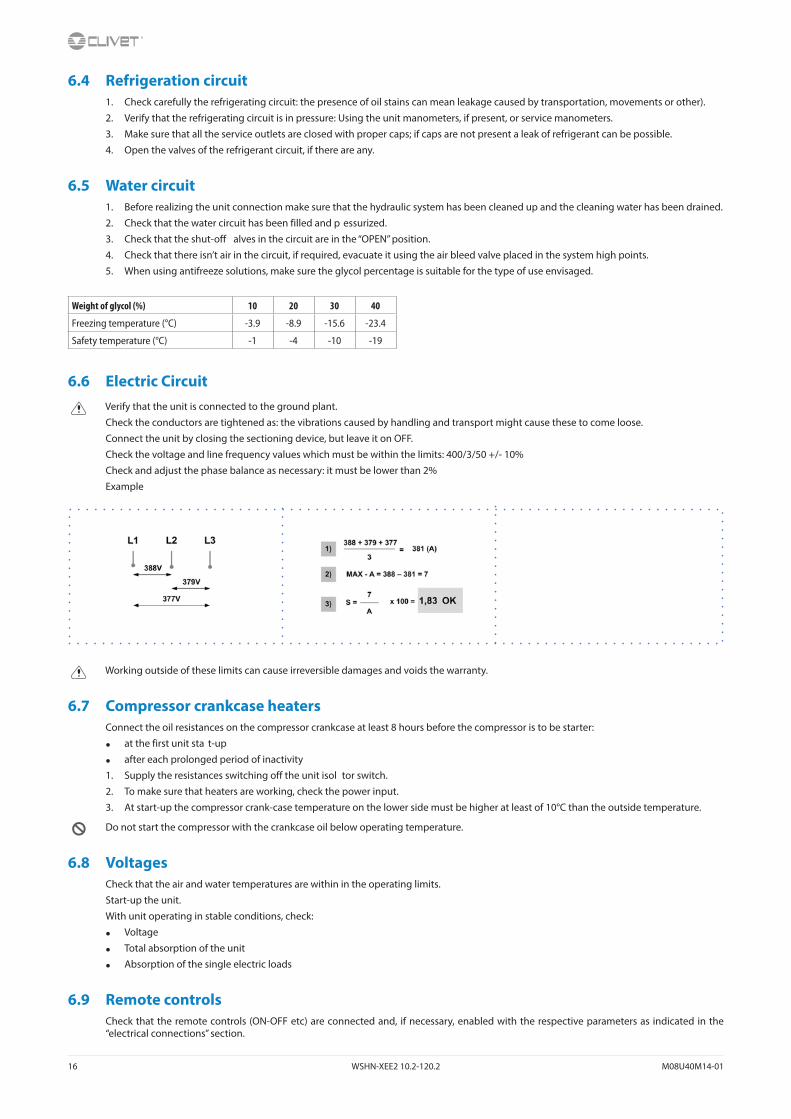
6.6 Electric CircuitVerify that the unit is connected to the ground plant.
Check the conductors are tightened as: the vibrations caused by handling and transport might cause these to come loose.
Connect the unit by closing the sectioning device, but leave it on OFF.
Check the voltage and line frequency values which must be within the limits: 400/3/50 +/- 10%
Check and adjust the phase balance as necessary: it must be lower than 2%
Example
Working outside of these limits can cause irreversible damages and voids the warranty.
6.7 Compressor crankcase heatersConnect the oil resistances on the compressor crankcase at least 8 hours before the compressor is to be starter:
• at the first unit sta t-up
• after each prolonged period of inactivity
1. Supply the resistances switching off the unit isol tor switch.
2. To make sure that heaters are working, check the power input.
3. At start-up the compressor crank-case temperature on the lower side must be higher at least of 10°C than the outside temperature.
Do not start the compressor with the crankcase oil below operating temperature.
6.8 VoltagesCheck that the air and water temperatures are within in the operating limits.
Start-up the unit.
With unit operating in stable conditions, check:
• Voltage
• Total absorption of the unit
• Absorption of the single electric loads
6.9 Remote controlsCheck that the remote controls (ON-OFF etc) are connected and, if necessary, enabled with the respective parameters as indicated in the “electrical connections” section.

M08U40M14-01 WSHN-XEE2 10.2-120.2 17
Check that probes and optional components are connected and enabled with the respective parameters (“electrical connections” section and following pages).
6.10 Demand limitMenu accessible only after having entered the password.
Access reserved only to specifically t ained personnel.
The parameter modific tion can cause irreversible damages.
It is possible to limit the absorbed electric power with an external signal 0-10 Vcc.
The higher the signal is, the lower the number of compressors available to meet the thermal need.
If only P0002: EnDemandLimit ≠ 0
Path: Main Menu / Unit parameters / Demand limit
Step Display Action Menu/Variable Keys Notes
1 Press 3 sec.
2 Password Set Password
3 Press
4 Main menu Select Unit parameters
5 Unit parameters Select Set Point
6 Set Point Select Demand limit
7 Set Demand limit
8 Confirm
9 Press 3 sec.
10 Select Local connections
Path: Main Menu / Unit parameters / Demand limit
Parameters Short description Description
P0200 setpointdemandlimit Parameter setting of the value % of demand limit

18 WSHN-XEE2 10.2-120.2 M08U40M14-01
6.11 Evaporator water fl w-rateCheck that the difference between the temperature of exchanger return and supply water corresponds to power according to this formula:
unit cooling power (kW) x 860 = Dt (°C) x fl w rate (L/h)
The cooling power is shown in the table of the GENERAL TECHNICAL DATA included in this manual, referred to specific conditions, or in the tables on COOLING PERFORMANCE in the TECHNICAL BULLETIN referred to various conditions of use.
Check for water side exchanger pressure drops:
determine the water fl w rate
measure the difference in pressure between exchanger input and output and compare it with the graph on WATER SIDE EXCHANGER PRESSURE DROPS
The measurement of pressure will be easier if pressure gauges are installed as indicated in the DIAGRAM OF SUGGESTED WATER CONNECTIONS.
6.12 Start-up reportIdentifying the operating objective conditions is useful to control the unit over time.
With unit at steady state, i.e. in stable and close-to-work conditions, identify the following data:
• total voltages and absorptions with unit at full load
• absorptions of the different electric loads (compressors, fans, pumps etc)
• temperatures and fl ws of the different fluids ( ater, air) both in input and in output from the unit
• temperature and pressures on the characteristic points of the refrigerating circuit (compressor discharge, liquid, intake)
The measurements must be kept and made available during maintenance interventions.
6.13 Operating at reduced loadThe units are equipped with partialization steps and they can, therefore, operate with reduced loads.
However a constant and long operation with reduced load with frequent stop and start-up of the compressor/s can cause serious damages for the lack of oil return.
The above-described operating conditions must be considered outside the operating limits.
In the event of compressor breakdown, due to operating in the above-mentioned conditions, the guarantee will not be valid and Clivet spa declines any responsibility.
Check periodically the average operating times and the frequency of the compressors starts: approximately the minimum thermal load should be such as to need the operating of a compressor for at least ten minutes.
If the average times are close to this limit, take the proper corrective actions.
6.14 97/23 CE PED directive97/23 CE PED DIRECTIVE gives instructions for installers, users and maintenance technicians as well.
Refer to local regulations; briefly and as an xample, see the following:
Compulsory verific tion of the first install tion:
• only for units assembled on the installer’s building site (for ex. Condensing circuit + direct expansion unit)
Certific tion of setting in service:
• for all the units
Periodical verific tions:
• to be executed with the frequency indicated by the Manufacturer (see the “maintenance inspections” paragraph)

M08U40M14-01 WSHN-XEE2 10.2-120.2 19
7 Control
7.1 LedINFO Not used
ALARM Blink / fixed = alarm present
CANCEL not used currently
7.2 DisplayRef. Variable Description
A Date - Time
B ActualSetPoint Temperature setting
C T.InH2OUtilitySide Water inlet temperature utility side
D T.OutH2OUtilitySide Water outlet temperature utility side
E ActualState On / off / eco / pmp On
F ActualMode Cool: water coolingHeat: Heating (not used)
2 Installed compressors
1 - 0Compressors ONexample: circuit 1 = 1 compr. Oncircuit 2 = 0 compr. On
50% Heating capacity
7.3 KeysSymbol Name Description
Info Main menu
Alarm Alarm display
CancelExitPrevious levelKeyboard settings
Up Increases value
Down Decreases value
Enter ConfirmPassword

20 WSHN-XEE2 10.2-120.2 M08U40M14-01
7.4 Change unit state
Step Display Action Menu/Variable Keys Notes
1 Press
2 Main menu Select Cmd Local state
3 Set OFF - ECO - ON - Pump On *
4 Confirm
6 Exit
* Local state
ECO: recurrent pump ON-OFF; compressors keep water system at setpoint ECO
Pmp ON: pump ON, compressor OFF
7.5 Change the modeStep Display Action Menu/Variable Keys Notes
1 Press
2 Main menu Select Cmd Local mode
3 Set Cool: water coolingHeat: HEATING
4 Confirm
5 Exit
7.6 Modify setpointStep Display Action Menu/Variable Keys Notes
1 Press
2 Main menu Select Unit parameters
3 Unit parameters Confirm Set Point
4 Select Set Point
5 Set Set Point
6 Confirm
7 Exit
Parameters Description
P0583 Setpoint Cool
P0584 2° Setpoint Cool Enable by remote switch
P0855 Economic summer SetPoint
P0577 Setpoint Heat
P0578 2° Setpoint Heat
P0579 Economic winter SetPoint
P0640 Recovery Set Point

M08U40M14-01 WSHN-XEE2 10.2-120.2 21
7.7 Display the status
Step Display Action Menu/Variable Keys Notes
1 Press
2 Main menu Select Machine State
3 Select General, circuit, ecc..
4 Exit
For details see:
7.8 SchedulerIt is possible to set 6 events (Off, Eco, On, Recirculating) for each week day.
Step Display Action Menu/Variable Keys Notes
1 Press
2 Main menu Select Scheduler
3 Scheduler Select Day
4 Select Time
5 Set Event time
6 Confirm
7 Select Value
8 Set On/Eco..
9 Confirm
10 Exit
Enable Scheduler
Step Display Action Menu/Variable Keys Notes
1 Press 3 sec.
2 Password Set Password
3 Press *
4 Main menu Select Unit Parameters
5 Select Option config
6 Set P0052=1
7 Press 3 sec.
Select Local connections
* Unit Parameters menu is displayed
22 WSHN-XEE2 10.2-120.2 M08U40M14-01
7.9 Alarms
Before resetting an alarm identify and remove its cause.
Repeated resets can cause irreversible damage.
Example:
+ eE0001: Phase monitor: Fault = active alarm
- EE0003: Pum 1 faulty: Ok = resetted alarm
Display of alarm: step 1-3
Reset allarm: step 4-10
Step Display Action Menu/Variable Keys Notes
1 Press
2 Alarm list detail Press
3 Alarm list Select Alarm
4 Alarm list detail Press 3 sec.
5 Password Set Enter password
6 Alarm list detail Press
7 Alarm list Select Alarm
8 Select ResetExecuted
9 Press 3 sec.
10 Password management Select Log off
For details see:
7.10 Keyboard settingsStep Display Action Menu/Variable Keys Notes
1 Press 3 sec.
2 Press
3 HMI Settings Select
4 Press
5 Press
6 Select Local connections

M08U40M14-01 WSHN-XEE2 10.2-120.2 23
8 Maintenance
8.1 General descriptionMaintenance must be done by authorized centres or by qualified personne .
The maintenance allows to:
• maintain the unit efficie y
• increase the life span of the equipment
• assemble information and data to understand the state of the unit efficie y and avoid possible damages
Before checking, please verify the following:
• the electrical power supply line should be isolated at the beginning
• the unit isolator is open, locked and equipped with the suitable warning
• make sure no tension is present
After turning off the p wer, wait at least 5 minutes before accessing to the electrical panel or any other electrical component.
Before accessing check with a multimeter that there are no residual stresses.
8.2 Inspections frequencyPerform an inspection every 6 months minimum.
The frequency, however, depends on the use.
In the event of frequent use it is recommended to plan inspections at shorter intervals:
• frequent use (continuous or very intermittent use, near the operating limits, etc)
• critical use (service necessary)
√ intervention frequency (months) 1 6 12
1 presence corrosion X
2 panel fixing X
3 water filter cleaning X
4 check the exchanger efficiency X
5 circulating pumps X
6 check of the fixing and the insulation of the power lead X
7 check of the earthing cable X
8 electric panel cleaning X
9 capacity contactor status X
10 termina closing, cable insulation integrity X
11 voltage and phase unbalancing (no load and on-load) X
12 absorptions of the single electrical loads X
13 test of the compressor crankcase heaters X
14 leak control* *
15 survey of the refrigerant circuit operating parameters X
16 safety valve *
17 protective device test: pressure switches, thermostats, flow switches etc.. X
18 control system test: setpoint, climatic compensations, capacity stepping, water / air flow-rate variations X
19 control device test: alarm signalling, thermometers, probes, pressure gauges etc.. X
* Refer to the local regulations; and ensure correct adherance. Companies and technicians that effect interventions of installation, maintenance/re-pairs, leak control and recovery must be CERTIFIED as expected by the local regulations. The leak control must be effected with annual renewal.
8.3 Unit bookletIt’s advisable to create a unit booklet to take notes of the unit interventions.
In this way it will be easier to adequately note the various interventions and aid any troubleshooting.
Report on the booklet:
• date
• type of intervention effected
• intervention description
• carried out measures etc.

24 WSHN-XEE2 10.2-120.2 M08U40M14-01
8.4 Standby modeIf a long period of inactivity is foreseen:
• turn off the p wer
• avoid the risk of frost (empty the system or add glycol)
Turn off the p wer to avoid electrical risks or damages by lightning strikes.
With lower temperatures keep heaters turned on in of the electrical panel (option).
It’s recommended that the re-start after the stopping period is performed by a qualified technician, especially after seasonal stops or seasonal switching.
When restarting, refer to what is indicated in the “start-up” section.
Schedule technical assistance in advance to avoid hitches and to guarantee that the system can be used when required.
8.5 Water side exchangerIt is very important for the exchanger to be able to provide the maximum thermal exchange, therefore it is essential for the inner surfaces to be clean of dirt and incrustations.
Periodically check the difference between the temperature of the supply water and the condensation temperature: if the difference is greater than 8°C–10°C it is advisable to clean the exchanger.
The clearing must be effected:
• with circulation opposite to the usual one
• with a speed at least 1,5 times higher than the nominal one
• with an appropriate product moderately acid (95% water + 5% phosphoric acid)
• after the cleaning rinse with water to inhibit the action of any residual product
8.6 Water fil erCheck that no impurities prevent the correct passage of water.
8.7 Circulating pumpsCheck:
• no leaks
• bearing status (anomalies are highlighted by abnormal noise and vibration)
• the terminal protection covers are closed and the cable holders are properly positioned
8.8 Flow Switch• controls the operations
• remove incrustations from the palette
8.9 Compressor supply line shut-off alve
A. Supply line shut-off alve
CAUTION!
Do not remove the seal
Remove only if authorized by the manufacturer.
Please contact the maker for informations.

M08U40M14-01 WSHN-XEE2 10.2-120.2 25
8.10 System discharge1. evacuate the system
2. open all drain valves in the low points of the unit hydraulic circuit
3. evacuate the exchanger, use all the cocks presents
4. use compressed air to blow the exchanger
5. dry completely the exchanger by an hot air jet; for greater safety fill the xchanger with glycoled solution
6. protect the exchanger from the air
7. remove the drain plugs to the pumps
Any anti-freeze liquid contained in the system should not be discharged freely as it is a pollutant.
It must be collected and reused.
Before starting a washing the plant.
Example
• emptying pump
It’s recommended that the re-start after the stopping period is performed by a qualified technician, especially after seasonal stops or seasonal switching.
When restarting, refer to what is indicated in the “start-up” section.
Schedule technical assistance in advance to avoid hitches and to guarantee that the system can be used when required.
8.11 Crankcase heaterCheck:
• closure
• Operation
8.12 Copeland scroll compressor

26 WSHN-XEE2 10.2-120.2 M08U40M14-01
9 Alarms
ELECTRICAL CIRCUIT ALARMS
Num Name Description Category
eE0001 Phase monitor Phase monitor fault Central
EE0003 Pump 1 faulty User side pump 1 overload protection GP Ut
EE0004 Pump 2 faulty User side pump 2 overload protection GP Ut
EE0005 Pump 3 faulty User side pump 3 overload protection GP Ut
eE0008 Utility Inverter Protection User side inverter overload protection GP Ut
ee0010 Master Offline Master unit offline MS
ee0011 Unit 2 in alarm 2nd slave unit fault MS
ee0012 Unit 2 OffLine 2nd slave unit offline MS
ee0013 Unit 3 in alarm 3rd slave unit fault MS
ee0014 Unit 3 OffLine 3rd slave unit offline MS
ee0015 Unit 4 in alarm 4th slave unit fault MS
ee0016 Unit 4 OffLine 4th slave unit offline MS
ee0017 Unit 5 in alarm 5th slave unit fault MS
ee0018 Unit 5 OffLine 5th slave unit offline MS
ee0019 Unit 6 in alarm 6th slave unit fault MS
ee0020 Unit 6 OffLine 6th slave unit offline MS
ee0021 Unit 7 in alarm /th slave unit fault MS
ee0022 Unit 7 OffLine /th slave unit offline MS
ee0027 Utility Water In temp Error User side in water temperature probe fault Central
ee0028 Utility Water Out temp Error User side out water temperature probe fault Central
ee0029 Temp Ext Sensor Error External air temperature probe fault HW
ee0030 DemandLimit Demand limit fault HW
ee0031 WaterReset Water reset fault HW
ee0032 External Humidity probe Error Relative humidity probe fault HW
ee0033 T.Quadro Ele Electrical panel temperature probe fault HW
ee0035 YV Cool Open YV Cool opening fault 4P
ee0036 YV Heat Open YV Heat opening fault 4P
ee0037 YV Cool Close YV Cool closing fault 4P
ee0038 YV Heat Close YV Heat closing fault 4P
ee0040 FCI Water Temp. Freecoling water temperature probe fault HW FCI
EE0044 Pump 1 Allarm Freecooling pump 1 overload protection FCI Circuit 1
EE0045 Pump 2 Allarm Freecooling pump 2 overload protection FCI Circuit 1
EE0046 Pump 3 Allarm Freecooling pump 3 overload protection FCI Circuit 1
ee0047 Pump Change for Utility Flow Switching pump on user side for flow alarm GP User side
ee0050 P.DifferenzialeUtil User side differential pressure sensore fault HW
EE0054 Recovery Pump 1 protection Recovery side pump 1 overload protection Recovery
EE0055 Recovery Pump 2 protection Recovery side pump 2 overload protection Recovery
EE0056 Recovery Pump 3 protection Recovery side pump 3 overload protection Recovery
eE0057 Recovery Inverter Protection Recovery side inverter overload protection Recovery
M08U40M14-01 WSHN-XEE2 10.2-120.2 27
Num Name Description Category
ee0100 TimeOutModPOL98U 1st POL98U module disconnected HW TimeOut
ee0101 TimeOutModPOL98U_2 2nd POL98U module disconnected HW TimeOut
ee0102 TimeOutModPOL96U POL96U module disconnected HW TimeOut
ee0103 TimeOutModPOL945 POL945 module disconnected HW TimeOut
ee0104 TimeOutModPOL965 POL965 module disconnected HW TimeOut
ee0105 TimeOutModPOL94U 1st POL94U module disconnected HW TimeOut
ee0106 TimeOutModPOL94U_2 2nd POL94U module disconnected HW TimeOut
ee0107 TimeOutModPOL985 POL985 module disconnected HW TimeOut
ee1001 T.Suction Gas Gas temperature probe 3 fault HW Circuit 1
ee1002 T.Suction Gas Gas temperature probe 5 fault HW Circuit 1
ee1003 P.Suction Heat Pressure sensor fault, low pressure heating HW Circuit 1
ee1004 EEV1 blocked EEV 1 blocked Circuit 1
ee1005 EEV1 blocked EEV2 blocked Circuit 1
EE1006 Comp 1 protections Compressor 1 overload protection Circuit 1
EE1007 Comp 2 protections Compressor 2 overload protection Circuit 1
EE1008 Comp 3 protections Compressor 3 overload protection Circuit 1
EE1009 Source Inverter Protection Source side inverter overload protection Source 1
ee1010 Pump Change for Source Flow Switching pump on source side for flow alarm Source 1
EE1013 Source Pump 1 protection Source side pump 1 overload protection Source 1
EE1014 Source Pump 2 protection Source side pump 2 overload protection Source 1
EE1015 Source Pump 3 protection Source side pump 3 overload protection Source 1
EE1018 Source side protection Source side ventilation overload protection Circuit 1
ee1022 T.Discharge C1.1 Compressor 1 discharge temperature probe fault HW Circuit 1
ee1023 T.Discharge C2.1 Compressor 2 discharge temperature probe fault HW Circuit 1
ee1024 T.Discharge C3.1 Compressor 3 discharge temperature probe fault HW Circuit 1
ee1025 T.Source 1 Source 1 temperature probe fault HW Circuit 1
ee1026 T.Source 2 Source 2 temperature probe fault HW Circuit 1
ee1027 T.Suction Gas Suction temperature probe fault HW Circuit 1
ee1028 P.Discharge High pressure probe fault HW Circuit 1
ee1029 P.Suction Low pressure probe fault HW Circuit 1
ee1030 T.GasRecovery Recovery exchanger gas temperature probe fault HW Circuit 1
ee1031 P.GasRecovery Recovery exchanger gas pressure probe fault HW Circuit 1
ee1032 T.Ing Recovery Recovery in temperature probe fault HW Circuit 1
ee1033 T.Out Recovery Recovery out temperature probe fault HW Circuit 1
ee1037 Alarm Inverter 1 Inverter 1 in alarm Inverter APY
ee1038 Alarm missing comunication inv1 Inverter 1 Modbus communication error Inverter APY
ee1039 Timeout comunication inv1 Inverter 1 communication timeout Inverter APY
ee1040 Alarm Inverter 2 Inverter 2 in alarm Inverter APY
ee1041 Alarm missing comunication inv2 Inverter 2 Modbus communication error Inverter APY
ee1042 Timeout comunication inv2 Inverter 2 communication timeout Inverter APY
ee1043 Alarm Inverter 3 Inverter 3 in alarm Inverter APY
ee1044 Alarm missing comunication inv3 Inverter 3 Modbus communication error Inverter APY
ee1045 Timeout comunication inv3 Inverter 3 communication timeout Inverter APY

28 WSHN-XEE2 10.2-120.2 M08U40M14-01
Num Name Description Category
EE1047 Alarm Envelop Comp1 Compressor 1 envelope alarm Circuit 1
EE1048 Alarm Envelop Comp2 Compressor 2 envelope alarm Circuit 1
EE1049 Alarm Envelop Comp3 Compressor 3 envelope alarm Circuit 1
ee1055 Alarm Inverter 1 Inverter 1 in alarm Inverter DFS
ee1056 Alarm missing comunication inv1 Inverter 1 communication error Inverter DFS
ee1057 Timeout comunication inv1 Inverter 1 communication timeout Inverter DFS
ee1058 Alarm Inverter 2 Inverter 2 in alarm Inverter DFS
ee1059 Alarm missing comunication inv2 Inverter 2 communication error Inverter DFS
ee1060 Timeout comunication inv2 Inverter 2 communication timeout Inverter DFS
ee1061 Alarm Inverter 3 Inverter 3 in alarm Inverter DFS
ee1062 Alarm missing comunication inv3 Inverter 3 communication error Inverter DFS
ee1063 Timeout comunication inv3 Inverter 3 communication timeout Inverter DFS
ee1070 User side ECV 1.1 User side ECV connection problem HW Circuit 1
ee1071 Source ECV 1.1 Source side ECV 1 connection problem HW Circuit 1
ee1072 Source ECV 2.1 Source side ECV 2 connection problem HW Circuit 1
ee2001 T.Suction Gas Gas temperature probe 4 fault HW Circuit 2
ee2002 T.Suction Gas Gas temperature probe 6 fault HW Circuit 2
ee2003 P.Suction Heat Pressure sensor fault, low pressure heating HW Circuit 2
ee2004 EEV1 blocked EEV1 blocked Circuit 2
ee2005 EEV1 blocked EEV2 blocked Circuit 2
EE2006 Comp 1 protections Compressor 1 overload protection Circuit 2
EE2007 Comp 2 protections Compressor 2 overload protection Circuit 2
EE2008 Comp 3 protections Compressor 3 overload protection Circuit 2
EE2009 Source Inverter Protection Source side inverter overload protection Source 2
ee2010 Pump Change for Source Flow Switching pump on source side for flow alarm Source 2
EE2013 Source Pump 1 protection Source side pump 1 overload protection Source 2
EE2014 Source Pump 2 protection Source side pump 2 overload protection Source 2
EE2015 Source Pump 3 protection Source side pump 3 overload protection Source 2
EE2018 Source side protection Source side ventilation overload protection Circuit 2
ee2022 T.Discharge C1.1 Compressor 1 discharge temperature probe fault HW Circuit 2
ee2023 T.Discharge C2.1 Compressor 2 discharge temperature probe fault HW Circuit 2
ee2024 T.Discharge C3.1 Compressor 3 discharge temperature probe fault HW Circuit 2
ee2025 T.Source 1 Source 1 temperature probe fault HW Circuit 2
ee2026 T.Source 2 Source 2 temperature probe fault HW Circuit 2
ee2027 T.Suction Gas Suction gas temperature probe fault HW Circuit 2
ee2028 P.Discharge High pressure probe fault HW Circuit 2
ee2029 P.Suction Low pressure probe fault HW Circuit 2
ee2030 T.GasRecovery Recovery exchanger gas temperature probe fault HW Circuit 2
ee2031 P.GasRecovery Recovery exchanger gas pressure probe fault HW Circuit 2
ee2032 T.Ing Recovery Recovery IN temperature probe fault HW Circuit 2
ee2033 T.Out Recovery Recovery OUT temperature probe fault HW Circuit 2
ee2037 Alarm Inverter 1 Inverter 1 in alarm Inverter APY
ee2038 Alarm missing comunication inv1 Inverter 1 communication error Inverter APY
M08U40M14-01 WSHN-XEE2 10.2-120.2 29
Num Name Description Category
ee2039 Timeout comunication inv1 Inverter 1 communication timeout Inverter APY
ee2040 Alarm Inverter 2 Inverter 2 in alarm Inverter APY
ee2041 Alarm missing comunication inv2 Inverter 2 communication error Inverter APY
ee2042 Timeout comunication inv2 Inverter 2 communication timeout Inverter APY
ee2043 Alarm Inverter 3 Inverter 3 in alarm Inverter APY
ee2044 Alarm missing comunication inv3 Inverter 3 communication error Inverter APY
ee2045 Timeout comunication inv3 Inverter 3 communication timeout Inverter APY
EE2047 Alarm Envelop Comp1 Compressor 1 envelope alarm Circuit 2
EE2048 Alarm Envelop Comp2 Compressor 2 envelope alarm Circuit 2
EE2049 Alarm Envelop Comp3 Compressor 3 envelope alarm Circuit 2
ee2055 Alarm Inverter 1 Inverter 1 in alarm Inverter DFS
ee2056 Alarm missing comunication inv1 Inverter 1 communication error Inverter DFS
ee2057 Timeout comunication inv1 Inverter 1 communication timeout Inverter DFS
ee2058 Alarm Inverter 2 Inverter 2 in alarm Inverter DFS
ee2059 Alarm missing comunication inv2 Inverter 2 communication error Inverter DFS
ee2060 Timeout comunication inv2 Inverter 2 communication timeout Inverter DFS
ee2061 Alarm Inverter 3 Inverter 3 in alarm Inverter DFS
ee2062 Alarm missing comunication inv3 Inverter 3 communication error Inverter DFS
ee2063 Timeout comunication inv3 Inverter 3 communication timeout Inverter DFS
ee2070 User side ECV 1.1 User side ECV connection problem HW Circuit 2
ee2071 Source ECV 1.1 Source side ECV 1 connection problem HW Circuit 2
ee2072 Source ECV 2.1 Source side ECV 2 connection problem HW Circuit 2

30 WSHN-XEE2 10.2-120.2 M08U40M14-01
REFRIGERANT CIRCUIT ALARMS
Num Name Description Category
ff1005 Min overheating EEV1 Value of refrigerant superheat too low EEV1 (user side) Circuit 1
ff1006 Min overheating EEV2 Value of refrigerant superheat too low EEV1 (source) Circuit 1
fF1009 Low Pressure Alarm (DI) Low Pressure Alarm (DI) Circuit 1
ff1010 Warning LP Cool Low Pressure Pre Alarm in Cooling Mode Circuit 1
ff1011 Warning LP Heat Low Pressure Pre Alarm in Heating Mode Circuit 1
fF1012 Low pressure Alarm Heat (AI) Low Pressure in Heating Mode (AI) Circuit 1
fF1013 High Pressure (DI) High Pressure Alarm (DI) Circuit 1
ff1014 Warning High Pressure High Pressure Pre Alarm Circuit 1
fF1015 High Pressure Alarm (AI) High Pressure Alarm (AI) Circuit 1
ff1016 Max RC Warning Maximum Pressure Ratio Pre Alarm Circuit 1
fF1017 Min RC Alarm Minimum Pressure Ratio Alarm Circuit 1
fF1018 Low Pressure Alarm Cool(AI) Low Pressure Alarm in Cooling Mode Circuit 1
FF1019 Max RC Alarm Maximum Pressure Ratio Circuit 1
FF1034 Vacuum Circuit Vacuum Alarm Circuit 1
FF1046 LimLp Low pressure limit Circuit 1
ff1047 DFRForced Defrost Forced Circuit 1
ff1048 DFRWaterTLow Low water temperature for defrost operation Circuit 1
ff1049 DFRTimeMax Defrost Maximum Time Circuit 1
ff2005 Min overheating EEV1 Min Superheat value (user side) Circuit 2
ff2006 Min overheating EEV2 Min Superheat value (source) Circuit 2
fF2009 Low Pressure Alarm (DI) Low pressure Alarm (DI) Circuit 2
ff2010 Warning LP Cool Low pressure Pre Alarm CoolingMode Circuit 2
ff2011 Warning LP Heat Low pressure Pre Alarm HeatingMode Circuit 2
fF2012 Low pressure Alarm Heat (AI) Low pressure Alarm Heating Mode (AI) Circuit 2
fF2013 High Pressure (DI) High pressure Alarm (DI) Circuit 2
ff2014 Warning High Pressure High pressure Pre Alarm Circuit 2
fF2015 High Pressure Alarm (AI) High pressure Alarm (AI) Circuit 2
ff2016 Max RC Warning Maximum pressure Ratio Pre Alarm Circuit 2
fF2017 Min RC Alarm Minimum pressure Ratio Alarm Circuit 2
fF2018 Low Pressure Alarm Cool(AI) Low Pressure Alarm Cooling Mode Circuit 2
FF2019 Max RC Alarm Maximum Pressure Radio Circuit 2
FF2034 Vacuum Circuit Vacuum Alarm Circuit 2
FF2046 LimLp Low pressure limit Circuit 2
ff2047 DFRForced Defrost Forced Circuit 2
ff2048 DFRWaterTLow Low water temperature for defrost Circuit 2
ff2049 DFRTimeMax Defrost Time Circuit 2

M08U40M14-01 WSHN-XEE2 10.2-120.2 31
HYDRAULIC CIRCUIT ALARMS
Num Name Description Category
iI0002 Water pressure User side low water pressure GP Ut
iI0006 Flow switch utility side User side low flow rate GP Ut
II0007 Freeze alarm User side Water Frost Protection Centrale
ii0008 Pumps antifreeze alarm Pump activation Water Frost Protection Centrale
II0009 Inconsistent deltaT across the exchanger Water outlet temperature, discordant with the current operation mode, user side Centrale
II0042 Pressure allarm Freecooling low water pressure FCI Circuito 1
II0043 Freeze alarm Freecooling water frost protection FCI Circuito 1
ii0047 Flow switch allarm Freecooling water low flow rate FCI Circuito 1
iI0052 Recovery Low H2O Flow Recovery water low flow rate Recupero
iI0053 Recovery Low Pressure Plant Recovery low water pressure Recupero
iI1017 Source Low Pressure Plant Source low water pressure Sorgente 1
iI1020 Source Low H2O Flow Source side low water flow Sorgente 1
II1021 Source H2O Freeze Alarm Source side water frost protection Sorgente 1
iI2017 Source Low Pressure Plant Source low water pressure Sorgente 2
iI2020 Source Low H2O Flow Source side low water flow Sorgente 2
II2021 Source H2O Freeze Alarm Source side water frost protection Sorgente 2

32 WSHN-XEE2 10.2-120.2 M08U40M14-01
10 Accessories
10.1 LonWorks
LED BSP communication with AP1 module LED BUS communication with LonWorksgreen communication ok green ready for communicationyellow software ok but communication with AP1
downyellow startup
red flashing: software error red flashing: communicating not possiblefixed: hardware error communication down
10.2 BACnet IP
LED BSP communication with AP1 module LED BUS communication with BACnetgreen communication ok green ready for communicationyellow software ok but communication with AP1
downyellow startup
red flashing: software error red BACnet server downfixed: hardware error restart after 3 sec

M08U40M14-01 WSHN-XEE2 10.2-120.2 33
10.3 Modbus - RS485
LED BSP communication with AP1 module LED BUS communication with Modbusgreen communication ok green communication okyellow software ok but communication with AP1
downyellow startup / channel not communicating
red flashing: software error red communication downfixed: hardware error
A Unit B Metal conduitC Metal septums D Metal-lined sheath (sleeve)
Modbus / LonWorks / BACnet Cable requirementsCouple of conductors twisted and shielded
Section of conductor 0,22mm2…0,35mm2
Nominal capacity between conductors < 50 pF/m
Nominal impedance 120 Ω
Recommended cable BELDEN 3106A
• Every RS485 serial line must be set up using the ‘In/Out’ bus system.
• Other types of networks are not allowed, such as Star or Ring networks.
• The difference in potential between the earth of the two RS485 devices that the cable shielding needs to be connected to must be lower than 7 V
• There must be suitable arresters to protect the serial lines from the effects of atmospheric discharges
• A 120 ohm resistance must be located on the end of the serial line. Alternatively, when the last serial board is equipped with an internal terminator, it must be enabled using the specific jumpe , dip switch or link.
• The cable must have insulation features and non-flame p opagation in accordance with applicable regulations.
• The RS485 serial line must be kept as far away as possible from sources of electromagnetic interference.

34 WSHN-XEE2 10.2-120.2 M08U40M14-01
10.4 RCTX - Remote control
1 Distance up to 350 mt A User interface2 Distance up to 700 mt B = B1 KNX bus, max 350 mt
twisted pair with shield, ø 0,8 mmEIB/KNX cable marking recommende
C PSX - Mains power supply unitpwer supply unit N125/11 5WG1 125-1AB11
C1 AC 120...230V, 50...60HzD KNX bus, max 350 mt
10.5 PSX - Mains power supply unit
pwer supply unit N125/11 5WG1 125-1AB11

M08U40M14-01 WSHN-XEE2 10.2-120.2 35
10.6 ECOSHARE function for the automatic management of a group of units
• Max 7 units
• Maximum length of the bus line: 700 m.
• Maximum distance between 2 units: 300 m
• Type of cable: shielded twisted pair cable Ø 0,8 mm. use an EIB/KNX cable
• Possible connections: Tree, star, in/out bus, mixed
• It is not possible to use a ring connection
• No end-of-line resistor or terminator required
• There must be suitable arresters to protect the serial lines from the effects of atmospheric discharges
• The data line must be kept separate from the power conductors or powered at different voltage values and away from possible sources of electrical interference

36 WSHN-XEE2 10.2-120.2 M08U40M14-01
If there are more units connected in a local network set the mode of operation.
MODE AEvery unit manages its own compressors according to the setpoint.
Every unit optimizes its refrigeration circuits.
Pumps always active, even with compressor stoped.
P0658 = 0
P0657 > 0 °C
setpoint1 > setpoint2 > setpoint3
or
setpoint1 < setpoint2 < setpoint3
MODE BThe master manages the single cooling.
The master optimizes individual refrigerant circuits.
Pumps always active, even with compressor stoped.
P0658 = 1
P0657 = 0 °C
setpoint1 = setpoint2 = setpoint3
plus: optimal H2O temperature control
MODE CThe master manages the single cooling.
The master optimizes individual refrigerant circuits.
Active pumps only with active compressors.
P0658 = 2
P0657 = 0 °C
setpoint1 = setpoint2 = setpoint3
plus: minimum pumps consumption need balanced system (t1 = t2 = t3)
Path: Main Menu / Unit parameters / Master Slave
Parameters Description
P0655 Number of network-connected units including the master
P0656 Number of units kept in standby
P0657 Temperature Offset the master sum or subtract, depending on the way you set, in order of priority, to the set point of the slave
P0658 Operation mode: 0=mode A; 1=mode B; 2=mode C
P0659 ProcessBus address unit

M08U40M14-01 WSHN-XEE2 10.2-120.2 37
10.7 Climatic TExt
Menu accessible only after having entered the password.
Access reserved only to specifically t ained personnel.
The parameter modific tion can cause irreversible damages.
The setpoint defined y the temperature curve is shown at status S0052: ActualUtSetp
Only if P0036: EnCompExt ≠ 0
Path: Main Menu / Unit parameters / TExt Correction confi
Example
Step Display Action Menu/Variable Keys Notes
1 Press 3 sec.
2 Password Set Password
3 Press
4 Main menu Select Unit parameters
5 Unit parameters Select Climatic TExt
6 Climatic TExt (pwd) Select Parameter
7 Set
8 Confirm
9 Press 3 sec.
10 Select Local connections
Path: Main Menu / Unit parameters / TExt Correction config
Parameters Description
P0606 setpoint temperature value when the air temperature value is AirAtSptLowC
P0607 external air temperature value where the calculated setpoint takes on the value given by CSptLow
P0608 setpoint temperature value when the air temperature value is AirAtSptHigC
P0609 external air temperature value where the calculated setpoint takes on the value given by CSptHigh
P0610 setpoint temperature value when the air temperature value is AirAtSptLowH
P0611 external air temperature value where the calculated setpoint takes on the value given by HSptLow
P0612 setpoint temperature value when the air temperature value is AirAtSptHigH
P0613 external air temperature value where the calculated setpoint takes on the value given by HSptHigh
P0606 / P0609: CooolingP0610 / P0613: Heating

38 WSHN-XEE2 10.2-120.2 M08U40M14-01
10.8 Water reset
Menu accessible only after having entered the password.
Access reserved only to specifically t ained personnel.
The parameter modific tion can cause irreversible damages.
It is possible to limit the absorbed electric power with an external signal 0-10 Vcc.
The water reset correction affects the setpoint defined y the Climate curve TExt (actual setpoint).
The setpoint is shown at status S0052: ActualUtSetp
Only if P0003: En WaterReset ≠ 0
Path: Main menu / Unit parameters / Water reset confi
Step Display Action Menu/Variable Keys Notes
1 Press 3 sec.
2 Password Set Password
3 Press
4 Main menu Select Unit parameters
5 Unit parameters Select Water reset
6 Water reset Select Parameter
7 Set
8 Confirm
9 Press 3 sec.
10 Select Local connections
Path: Main Menu / Unit parameters / Water reset
Parameters Description
P0616 Maximum correction to be applied to the setpoint Cooling
P0617 Value of the WR control signal corresponding to the correction of the set Cool equal to P0616
P0618 Value of the WR control signal corresponding to the correction of the set COOL equal to 0
P0615 Maximum correction to be applied to the setpoint Heating
P0619 Value of the WR control signal corresponding to the correction of the set Heating equal to P0615
P0620 Value of the WR control signal corresponding to the correction of the set Heating equal to 0
P0616 / P0618: Cooling P0615, P0619, P0620: Heating
M08U40M14-01 WSHN-XEE2 10.2-120.2 39
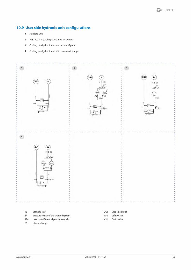
10.9 User side hydronic unit configu ations1 standard unit
2 VARYFLOW + (cooling side 2 inverter pumps)
3 Cooling side hydronic unit with an on-off pump
4 Cooling side hydronic unit with two on-off pumps
IN user side inlet OUT user side outletSP pressure switch of the charged system VSU safety valvePDU User side differential pressure switch VSR Drain valveSC plate exchanger

40 WSHN-XEE2 10.2-120.2 M08U40M14-01
10.10 Source side hydhydronic assembly configu ations
1 standard unit 4 Source side hydronic unit with 2 ON/OFF pumps
2 VARYFLOW + (heating side 2 inverter pumps) 5 Source side 3-way modulating valve
3 Source side hydronic unit with 1 ON/OFF pump 6 Source side 2-way modulating valve
IN Source inlet OUT source outletSP pressure switch of the charged system VSS safety valvePDS Source side differential pressure switch VSR Drain valveSC plate exchanger
M08U40M14-01 WSHN-XEE2 10.2-120.2 41
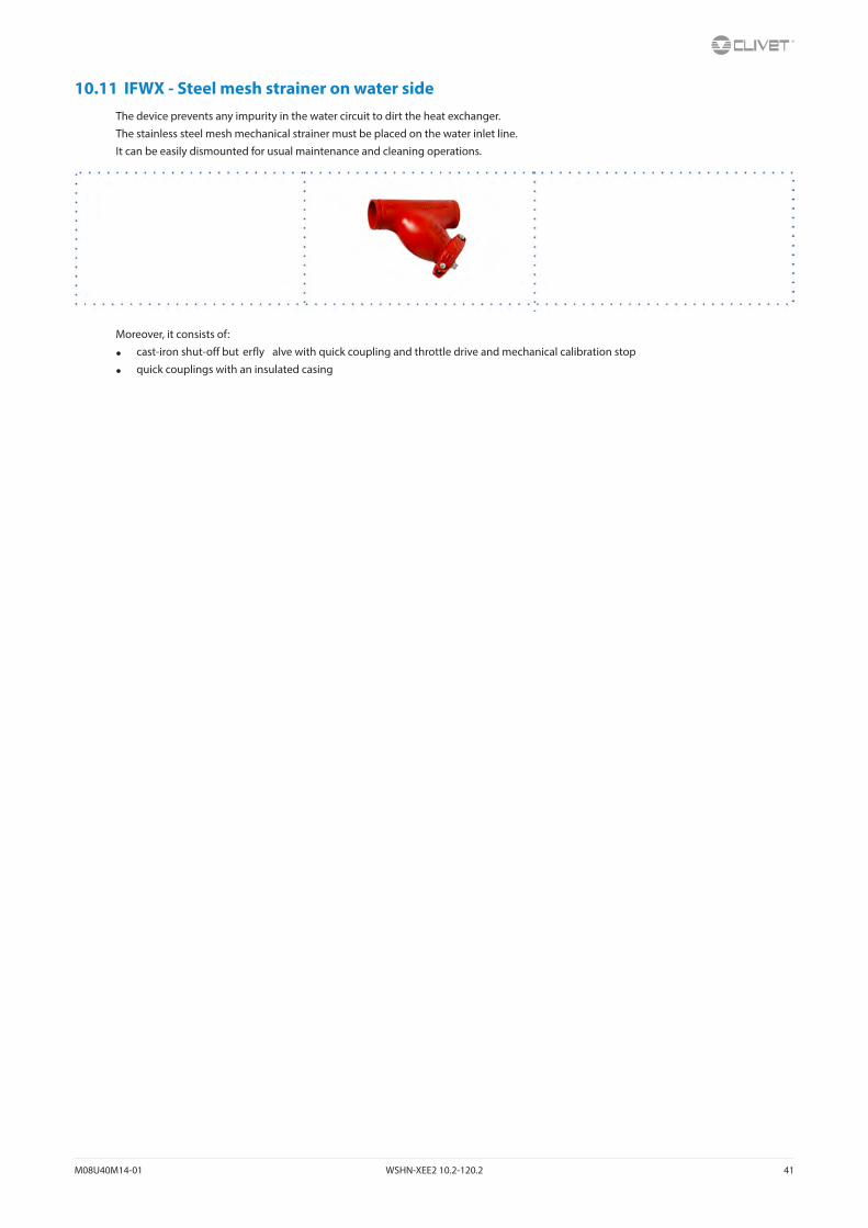
10.11 IFWX - Steel mesh strainer on water sideThe device prevents any impurity in the water circuit to dirt the heat exchanger.
The stainless steel mesh mechanical strainer must be placed on the water inlet line.
It can be easily dismounted for usual maintenance and cleaning operations.
Moreover, it consists of:
• cast-iron shut-off but erfly alve with quick coupling and throttle drive and mechanical calibration stop
• quick couplings with an insulated casing
42 WSHN-XEE2 10.2-120.2 M08U40M14-01
11 Decommissioning
11.1 DisconnectingOnly authorised personnel must disconnect the unit.
Avoid leak or spills into the environment.
Before disconnecting the unit, the following must be recovered, if present:
• refrigerant gas
• anti-freeze solutions in the water circuit
Awaiting dismantling and disposal, the unit can also be stored outdoors, if the electrical, cooling and water circuits of the unit have 100% integrity and are isolated, bad weather and rapid change in temperature will not result in any environmental impact.
11.2 Dismantling and disposalThe unit must always be sent to authorised centres for dismantling and disposal.
When dismantling the unit, the fan, the motor and the coil, if operating, may be recovered by the specialist centres for reuse.
All the materials must be recovered or disposed of in compliance with the corresponding national standards in force.
For further information on the decommissioning of the unit, contact the manufacturer.
11.3 Directive EC RAEEThe units covered by the legislation in question are marked with the symbol on the side.
With the aim of protecting the environment, all of our units are produced in compliance with Directive EC on waste electrical and electronic equipment (RAEE).
The potential effects on the environment and on human health due to the presence of hazardous substances are shown in the use and maintenance manual in the section on residual risks.
Information in addition to that indicated below, if required, can be obtained from the manufacturer/distributor/importer, who are responsible for the collection/handling of waste originating from equipment covered by EC-RAEE. This information is also available from the retailer who sold this appliance or from the local authorities who handle waste.
Directive EC-RAEE requires disposal and recycling of electrical and electronic equipment as described therein to be handled through appropriate collection, in suitable centres, separate from collection for the disposal of mixed urban waste.
The user must not dispose of the unit at the end of its life cycle as urban waste, it must instead be handed over to appropriate collection centres as set forth by current standards or as instructed by the distributor.

M08U40M14-01 WSHN-XEE2 10.2-120.2 43
12 Residual risks
General descriptionIn this section the most common situations are indicated,as these cannot be controlled by the manufacturer and could be a source of risk situations for people or things.Danger zoneThis is an area in which only an authorised operator may work.The danger zone is the area inside the unit which is accessible only with the deliberate removal of protections or parts thereof.HandlingThe handling operations, if implemented without all of the protec-tion necesssary and without due caution, may cause the drop or the tipping of the unit with the consequent damage, even serious, to persons, things or the unit itself.Handle the unit following the instructions provided in the present manual regarding the packaging and in compliance with the local regulations in force.Should the refrigerant leak please refer to the refrigerant “Safety sheet”.InstallationThe incorrect installation of the unit could cause water leaks, condensate accumulation, leaking of the refrigerant, electric shock, poor operation or damage to the unit itself.Check that the installation has been implemented by qualified technical personnel only and that the instructions contained in the present manual and the local regulations in force have been adhered to.The installation of the unit in a place where even infrequent leaks of inflammable gas and the accumulation of this gas in the area sur-rounding the area occur could cause explosions or fires.Carefully check the positioning of the unit.The installation of the unit in a place unsuited to support its weight and/or guarantee adequate anchorage may result in consequent damage to things, people or the unit itself.Carefully check the positioning and the anchoring of the unit.Easy access to the unit by children, unauthorised persons or animals may be the source of accidents, some serious.Install the unit in areas which are only accessible to authorised person and/or provide protection against intrusion into the danger zone.General risksSmell of burning, smoke or other signals of serious anomalies may indicate a situation which could cause damage to people, things or the unit itself.Electrically isolate the unit (yellow-red isolator).Contact the authorised service centre to identify and resolve the problem at the source of the anomaly.Accidental contact with exchange batteries, compressors, air deliv-ery tubes or other components may cause injuries and/or burns.Always wear suitable clothing including protective gloves to work inside the danger zone.Maintenance and repair operations carried out by non-qualified personnel may cause damage to persons, things or the unit itself.Always contact the qualified assistance centre.Failing to close the unit panels or failure to check the correct tightening of all of the panelling fixing screws may cause damage to persons, things or the unit itself.Periodically check that all of the panels are correctly closed and fixed.
If there is a fire the temperature of the refrigerant could reach values that increase the pressure to beyond the safety valve with the consequent possible projection of the refrigerant itself or explosion of the circuit parts that remain isolated by the closure of the tap.Do not remain in the vicinity of the safety valve and never leave the refrigerating system taps closed.Electric partsAn incomplete attachment line to the electric network or with incor-rectly sized cables and/or unsuitable protective devices can cause electric shocks, intoxication, damage to the unit or fires.Carry out all of the work on the electric system referring to the electric layout and the present manual ensuring the use of a system thereto dedicated.An incorrect fixing of the electric components cover may lead to the entry of dust, water etc inside and may consequently electric shocks, damage to the unit or fires.Always fix the unit cover properly.When the metallic mass of the unit is under voltage and is not correctly connected to the earthing system it may be as source of electric shock and electrocution.Always pay particular attention to the implementation of the earth-ing system connections.Contact with parts under voltage accessible inside the unit after the removal of the guards can cause electric shocks, burns and electrocution.Open and padlock the general isolator prior to removing the guards and signal work in progress with the appropriate sign.Contact with parts that could be under voltage due to the start up of the unit may cause electric shocks, burns and electrocution.When voltage is necessary for the circuit open the isolator on the attachment line of the unit itself, padlock it and display the appro-priate warning sign.Moving partsContact with the transmissions or with the fan aspiration can cause injuries.Prior to entering the inside of the unit open the isolater situated on the connection line of the unit itself, padlock and display the appropriate warning sign.Contact with the fans can cause injury.Prior to removing the protective grill or the fans, open the isolator on the attachment line of the unit itself, padlock it and display the appropriate warning sign.RefrigerantThe intervention of the safety valve and the consequent expulsion of the gas refrigerant may cause injuries and intoxication.Always wear suitable clothing including protective gloves and eyeglasses for operations inside the danger zone.Should the refrigerant leak please refer to the refrigerant “Safety sheet”.Contact between open flames or heat sources with the refrigerant or the heating of the gas circuit under pressure (e.g. during welding operations) may cause explosions or fires.Do not place any heat source inside the danger zone.The maintenance or repair interventions which include welding must be carried out with the system off.Hydraulic partsDefects in tubing, the attachments or the removal parts may cause a leak or water projection with the consequent damages to people, things or shortcircuit the unit.

BT14G004GB-02 ELFOEnergy Ground Medium2 44
General technical dataGroundwater version
Size 10.2 12.2 14.2 16.2 19.2 22.2 27.2 30.2 35.2 40.2 43.2 45.2 50.2 55.2 60.2 70.2 80.2 90.2 100.2 120.2
Radiant panels
Heating
Heating capacity (EN14511:2013) 1 35,0 41,1 49,1 58,0 68,8 81,4 94,8 107 120 141 152 162 183 200 223 258 286 321 351 421
Total power input (EN14511:2013) 2 6,58 7,77 9,47 11,1 13,1 16,2 17,7 20,6 23,7 27,0 30,1 32,8 34,7 38,5 43,7 49,1 55,7 63,3 68,9 83,3
COP (EN 14511:2013) 3 5,32 5,29 5,18 5,23 5,27 5,02 5,36 5,19 5,05 5,21 5,06 4,93 5,28 5,21 5,11 5,25 5,13 5,07 5,10 5,06
Cooling
Cooling capacity (EN14511:2013) 6 kW 40,3 47,1 56,1 66,6 79,1 92,6 108 121 135 162 179 189 212 229 155 295 325 360 393 468
Total power input (EN14511:2013) 2 kW 6,59 8,15 10,1 11,7 13,7 16,7 18,5 21,4 25,2 28,5 32,3 34,2 37,2 40,9 46,7 53,6 61,6 66,2 72,9 86,9
EER (EN 14511:2013) 7 6,12 5,78 5,58 5,68 5,76 5,55 5,84 5,66 5,35 5,70 5,52 5,52 5,69 5,60 5,46 5,51 5,27 5,43 5,39 5,38
Terminal units
Heating
Heating capacity (EN14511:2013) 4 29,2 34,4 40,7 48,4 57,7 67,6 82,0 91,8 102 120 131 138 155 168 187 217 240 265 292 347
Total power input (EN14511:2013) 2 6,40 7,50 9,10 10,6 12,5 15,4 17,5 20,5 23,6 26,8 29,9 31,7 34,2 37,7 42,6 48,2 54,5 61,4 67,8 81,7
COP (EN 14511:2013) 3 4,57 4,58 4,47 4,56 4,62 4,38 4,68 4,49 4,32 4,47 4,38 4,37 4,52 4,46 4,38 4,50 4,40 4,31 4,31 4,25
Cooling
Cooling capacity (EN14511:2013) 8 29,2 34,4 40,7 48,4 57,7 67,6 82,0 91,8 102 120 131 138 155 168 187 217 240 265 292 347
Total power input (EN14511:2013) 2 6,40 7,50 9,10 10,6 12,5 15,4 17,5 20,5 23,6 26,8 29,9 31,7 34,2 37,7 42,6 48,2 54,5 61,4 67,8 81,7
EER (EN 14511:2013) 7 4,57 4,58 4,47 4,56 4,62 4,38 4,68 4,49 4,32 4,47 4,38 4,37 4,52 4,46 4,38 4,50 4,40 4,31 4,31 4,25
ESEER 9 5,99 5,77 5,39 5,27 5,44 5,25 5,87 5,66 5,71 5,69 5,49 5,74 5,65 5,50 5,41 5,54 5,24 5,28 5,34 5,28
Radiators
Heating
Heating capacity (EN14511:2013) 5 31,7 37,6 44,6 52,4 61,6 73,2 88,3 99,4 112 132 145 154 166 181 202 233 259 291 314 375
Total power input (EN14511:2013) 2 10,3 12,2 14,4 16,5 19,4 23,0 26,3 29,8 34,7 39,4 44,3 47,0 50,7 55,8 63,3 70,2 78,6 92,5 103 127
COP (EN 14511:2013) 3 3,08 3,09 3,10 3,17 3,18 3,18 3,35 3,33 3,24 3,35 3,26 3,27 3,27 3,24 3,19 3,32 3,29 3,15 3,05 2,96
Compressor
Type of compressors Scroll Scroll Scroll Scroll Scroll Scroll Scroll Scroll Scroll Scroll Scroll Scroll Scroll Scroll Scroll Scroll Scroll Scroll Scroll Scroll
No. of compressors No 2 2 2 2 2 2 2 2 2 2 2 2 2 2 2 2 2 2 2 2
Std Capacity control steps No 3 3 2 3 3 3 3 2 3 3 3 3 3 3 2 3 2 3 3 2
Oil charge l 3,00 3,00 3,00 6,00 6,00 6,00 7,00 7,00 8,00 10,0 12,0 11,0 11,0 13,0 13,0 13,0 13,0 13,0 13,0 13,0
Refrigerant charge kg 4,7 5,2 6,0 8,2 9,1 11 12 14 17 20 22 23 24 26 29 33 34 37 38 41
Refrigeration circuits No 1 1 1 1 1 1 1 1 1 1 1 1 1 1 1 1 1 1 1 1
Internal exchanger
Type of internal exchanger 10 PHE PHE PHE PHE PHE PHE PHE PHE PHE PHE PHE PHE PHE PHE PHE PHE PHE PHE PHE PHE
No. of internal exchangers No 1 1 1 1 1 1 1 1 1 1 1 1 1 1 1 1 1 1 1 1
Water flow-rate (User Side) 8 l/s 1,40 1,70 2,00 2,30 2,80 3,30 3,90 4,40 4,90 5,70 6,30 6,60 7,40 8,10 9,00 10,4 11,5 12,7 14,4 16,7
External exchanger
Type of external exchanger 10 PHE PHE PHE PHE PHE PHE PHE PHE PHE PHE PHE PHE PHE PHE PHE PHE PHE PHE PHE PHE
No. of external exchangers No 1 1 1 1 1 1 1 1 1 1 1 1 1 1 1 1 1 1 1 1
Water flow rate (Source Side) 8 l/s 1,70 2,00 2,40 2,80 3,30 4,00 4,70 5,40 6,00 7,00 7,70 8,10 9,00 9,80 10,9 12,6 14,0 15,6 17,6 20,5
Connections
Water fittings (Standard units) 2’1/2 2’1/2 2’1/2 2’1/2 2’1/2 2’1/2 2’1/2 2’1/2 2’1/2 2’1/2 2’1/2 2’1/2 2’1/2 2’1/2 2’1/2 2’1/2 2’1/2 2’1/2 3’ 3’
Water fittings (Large units) 2’ 2’ 2’ 2’ 2’ 2’ 3’ 3’ 3’ 3’ 3’ 3’ 3’ 3’ 3’ 3’ 3’ 3’ 4’ 4’
Water circuit
Maximum water side pressure 11 MPa 1.0 1.0 1.0 1.0 1.0 1.0 1.0 1.0 1.0 1.0 1.0 1.0 1.0 1.0 1.0 1.0 1.0 1.0 1.0 1.0
Power supply
Standard power supply V 400/3/50 400/3/50 400/3/50 400/3/50 400/3/50 400/3/50 400/3/50 400/3/50 400/3/50 400/3/50 400/3/50 400/3/50 400/3/50 400/3/50 400/3/50 400/3/50 400/3/50 400/3/50 400/3/50 400/3/50
1. Data referred to the following conditions: Internal exchanger water 30/35 °C. External exchanger water 10/7 °C. Performance data calculated with reference to EN14511:2013
2. The total power draw is calculated by adding the compressor’s power draw + the draw required to overcome the internal service and source side pressure drops + the control circuit power draw
3. COP (EN 14511:2013) heating performance coefficient. Ratio between delivered heating capacity and power input in compliance with EN 14511:2013
4. Data referred to the following conditions: Internal exchanger water 40/45 °C. External exchanger water 10/7 °C. Performance data calculated with reference to EN14511:2013
5. Data referred to the following conditions: Internal exchanger water 50/55 °C. External exchanger water 10/7 °C. Performance data calculated with reference to EN14511:2013
6. Data referred to the following conditions: Internal exchanger water 23/18 °C. External exchanger water 30/35 °C. Performance data calculated with reference to EN14511:2013
7. EER (EN 14511:2013) cooling performance coefficient. Ratio between delivered cooling capacity and power input in compliance with EN 14511:2013
8. Data referred to the following conditions: Internal exchanger water 12/7°C. External exchanger water 30/35 °C. Performance data calculated with reference to EN14511:2013
9. ESEER calculated per EUROVENT, for installations with terminal units with water produced at 7 °C and constant source side flow10. PHE = plate exchanger 11. Conditions for the circuit on the utility side and the circuit on the source side. In configurations with hydronic units, the maximum
pressure on the water side is 600 kPa.

45 ELFOEnergy Ground Medium2 BT14G004GB-02
General technical dataGeothermic version
Size 10.2 12.2 14.2 16.2 19.2 22.2 27.2 30.2 35.2 40.2 43.2 45.2 50.2 55.2 60.2 70.2 80.2 90.2 100.2 120.2
Radiant panels
Heating
Heating capacity (EN14511:2013) 1 27,8 32,6 37,9 45,3 54,3 63,4 75,3 85,1 95,7 111 121 129 141 156 173 196 218 247 266 312
Total power input (EN14511:2013) 2 6,59 7,55 8,99 10,5 12,4 15,2 16,8 19,4 22,4 25,6 28,4 30,0 32,5 35,9 40,6 45,3 50,9 59,2 64,3 78,4
COP (EN 14511:2013) 3 4,22 4,32 4,22 4,29 4,37 4,18 4,49 4,39 4,28 4,33 4,27 4,31 4,34 4,33 4,26 4,34 4,29 4,17 4,14 3,98
Cooling
Cooling capacity (EN14511:2013) 6 37,8 43,7 50,8 61,3 76,4 87,9 106 119 135 156 172 183 202 221 247 281 310 357 399 467
Total power input (EN14511:2013) 2 7,31 9,08 11,2 12,8 14,3 17,5 18,3 21,1 25,1 28,6 32,1 33,4 37,3 40,7 46,2 53,4 61,4 68,4 75,8 91,0
EER (EN 14511:2013) 7 5,17 4,82 4,55 4,78 5,34 5,02 5,79 5,63 5,40 5,45 5,37 5,49 5,42 5,42 5,33 5,26 5,04 5,22 5,26 5,12
Terminal units
Heating
Heating capacity (EN14511:2013) 4 27,4 32,2 37,5 44,7 53,1 62,3 73,5 83,0 93,4 108 119 127 138 153 170 194 214 244 263 309
Total power input (EN14511:2013) 2 8,30 9,60 11,0 13,1 15,4 18,3 20,6 23,4 27,1 31,0 34,4 36,6 39,6 43,9 49,7 55,2 61,6 72,6 78,6 96,4
COP (EN 14511:2013) 3 3,29 3,36 3,40 3,41 3,46 3,40 3,57 3,54 3,45 3,50 3,44 3,47 3,49 3,48 3,42 3,51 3,48 3,36 3,34 3,21
Cooling
Cooling capacity (EN14511:2013) 8 kW 28,5 33,2 38,2 45,8 57,0 65,6 80,8 90,9 103 119 130 142 153 167 187 213 237 264 296 343
Total power input (EN14511:2013) 2 kW 7,00 8,30 10,1 11,6 13,0 16,1 17,5 20,3 23,5 26,9 29,8 31,4 34,5 37,6 42,6 48,5 55,0 62,8 69,4 84,2
EER (EN 14511:2013) 7 4,06 3,98 3,78 3,96 4,39 4,09 4,63 4,48 4,36 4,41 4,37 4,52 4,44 4,45 4,39 4,39 4,33 4,22 4,27 4,08
Radiators
Heating
Heating capacity (EN14511:2013) 5 kW 25,7 30,5 35,3 42,0 49,6 58,7 68,3 77,9 87,7 101 111 120 130 144 162 183 202 228 245 288
Total power input (EN14511:2013) 2 kW 10,5 12,2 14,0 16,5 19,2 22,5 25,8 29,1 33,7 38,2 42,7 45,4 49,3 54,3 61,7 67,9 75,1 90,5 98,0 122
COP (EN 14511:2013) 3 2,44 2,51 2,52 2,55 2,58 2,61 2,64 2,68 2,60 2,65 2,61 2,65 2,65 2,65 2,63 2,70 2,70 2,51 2,50 2,36
Compressor
Type of compressors Scroll Scroll Scroll Scroll Scroll Scroll Scroll Scroll Scroll Scroll Scroll Scroll Scroll Scroll Scroll Scroll Scroll Scroll Scroll Scroll
No. of compressors No 2 2 2 2 2 2 2 2 2 2 2 2 2 2 2 2 2 2 2 2
Std Capacity control steps No 3 3 2 3 3 3 3 2 3 3 3 3 3 3 2 3 2 3 3 2
Oil charge l 3,00 3,00 3,00 6,00 6,00 6,00 7,00 7,00 8,00 10,0 12,0 11,0 11,0 13,0 13,0 13,0 13,0 13,0 13,0 13,0
Refrigerant charge kg 4,7 5,2 6,0 8,2 9,1 11 12 14 17 20 22 23 24 26 29 33 34 37 38 41
Refrigeration circuits No 1 1 1 1 1 1 1 1 1 1 1 1 1 1 1 1 1 1 1 1
Internal exchanger
Type of internal exchanger 9 PHE PHE PHE PHE PHE PHE PHE PHE PHE PHE PHE PHE PHE PHE PHE PHE PHE PHE PHE PHE
No. of internal exchangers No 1 1 1 1 1 1 1 1 1 1 1 1 1 1 1 1 1 1 1 1
Water flow-rate (User Side) 8 l/s 1,40 1,60 1,80 2,20 2,70 3,20 3,90 4,40 5,10 5,70 6,30 6,80 7,50 8,30 9,00 10,2 11,4 12,6 14,2 16,5
External exchanger
Type of external exchanger 9 PHE PHE PHE PHE PHE PHE PHE PHE PHE PHE PHE PHE PHE PHE PHE PHE PHE PHE PHE PHE
No. of external exchanger No 1 1 1 1 1 1 1 1 1 1 1 1 1 1 1 1 1 1 1 1
Water flow rate (Source Side) 8 l/s 1,80 2,10 2,50 2,90 3,60 4,10 5,0 5,7 6,4 7,4 8,2 8,9 9,6 10,5 11,7 13,4 14,9 16,6 18,7 21,8
Connections
Water fittings (Standard units) 1’ 1/4 1’ 1/4 1’ 1/4 1’ 1/4 1’ 1/4 1’ 1/4 2’1/2 2’1/2 2’1/2 2’1/2 2’1/2 2’1/2 2’1/2 2’1/2 2’1/2 2’1/2 2’1/2 2’1/2 3’ 3’
Water fittings (Large units) 2’ 2’ 2’ 2’ 2’ 2’ 3’ 3’ 3’ 3’ 3’ 3’ 3’ 3’ 3’ 3’ 3’ 3’ 4’ 4’
Power supply
Standard power supply V 400/3/50 400/3/50 400/3/50 400/3/50 400/3/50 400/3/50 400/3/50 400/3/50 400/3/50 400/3/50 400/3/50 400/3/50 400/3/50 400/3/50 400/3/50 400/3/50 400/3/50 400/3/50 400/3/50 400/3/50
1. Data referred to the following conditions: Internal exchanger water 30/35 °C. External exchanger water 0/-3 °C. Operation with 30% source side mixture of water and propylene glycol. Performance data calculated with reference to EN14511:2013
2. The total power draw is calculated by adding the compressor’s power draw + the draw required to overcome the internal service and source side pressure drops + the control circuit power draw
3. COP (EN 14511:2013) heating performance coefficient. Ratio between delivered heating capacity and power input in compliance with EN 14511:2013
4. Data referred to the following conditions: Internal exchanger water 40/45°C. External exchanger water 0/-3 °C. Operation with 30% source side mixture of water and propylene glycol. Performance data calculated with reference to EN14511:2013
5. Data referred to the following conditions: Internal exchanger water 50/55°C. External exchanger water 0/-3 °C. Operation with 30% source side mixture of water and propylene glycol. Performance data calculated with reference to EN14511:2013
6. Data referred to the following conditions: Internal exchanger water 23/18 °C. External exchanger water 30/35 °C. Operation with 30% source side mixture of water and propylene glycol. Performance data calculated with reference to EN14511:2013
7. EER (EN 14511:2013) cooling performance coefficient. Ratio between delivered cooling capacity and power input in compliance with EN 14511:2013
8. Data referred to the following conditions: Internal exchanger water 12/7°C. External exchanger water 30/35 °C. Operation with 30% source side mixture of water and propylene glycol. Performance data calculated with reference to EN14511:2013
9. PHE = plate exchanger

BT14G004GB-02 ELFOEnergy Ground Medium2 46
Sound levels
Size
Sound power level (dB)Sound
power levelSound
pressure levelOctave band (Hz)
63 125 250 500 1000 2000 4000 8000 dB(A) dB(A)
10.2 78 70 62 52 52 43 41 40 60 44
12.2 78 69 62 56 52 44 43 38 60 44
14.2 78 67 61 57 54 46 44 39 60 45
16.2 78 71 66 63 53 49 46 41 64 49
19.2 78 73 67 63 55 51 47 42 65 49
22.2 78 73 65 62 55 52 47 42 64 49
27.2 78 73 66 62 56 54 49 44 64 49
30.2 78 74 63 60 56 54 48 44 64 49
35.2 81 83 80 67 61 61 52 45 74 58
40.2 81 79 80 67 65 63 55 50 74 58
43.2 81 83 83 69 66 65 56 49 77 60
45.2 81 78 80 69 66 62 55 48 74 58
50.2 81 83 83 70 67 64 56 47 77 60
55.2 81 80 83 70 68 65 57 50 77 60
60.2 81 80 83 71 69 65 57 50 77 61
70.2 82 80 85 73 72 68 60 51 79 63
80.2 82 80 85 73 74 70 61 52 80 63
90.2 83 81 86 74 75 71 62 53 81 64
100.2 83 81 86 74 75 71 62 53 81 64
120.2 84 82 87 75 76 72 63 54 82 65
Sound levels refer to units with full load under nominal test conditions.The sound pressure level refers to a distance of 1 meter from the outer surface of the unit operating in open field.Noise levels are determined using the tensiometric method (UNI EN ISO 9614-2)Data referred to the following conditions:Entering / leaving exchanger water temperature user side 12/7°CEntering / leaving exchanger water temperature source side 30/35°C

47 ELFOEnergy Ground Medium2 BT14G004GB-02
Operating Range (Cooling)Size 10.2 - 12.2 - 14.2 Size 16.2
Size 19.2-22.2-27.2-30.2-35.2-40.2-45.2 Sizes 43.2-50.2-55.2-60.2-70.2-80.2-90.2-100.2-120.2
Twu [°C] = leaving water temperature user sideTws [°C] = leaving water temperature source sideThe limits refer to DT=5 °C on both the user and source sides(1) Normal operating range(2)Operating range with modulating valve or inverter pump on source side in regulation mode (optional configurations)

BT14G004GB-02 ELFOEnergy Ground Medium2 48
Operating Range (Heating)Size 10.2 - 12.2 - 14.2 Size 16.2
Size 19.2-22.2-27.2-30.2-35.2-40.2-45.2 Sizes 43.2-50.2-55.2-60.2-70.2-80.2-90.2-100.2-120.2
Twu [°C] = leaving water temperature user sideTws [°C] = leaving water temperature source sideThe limits refer to DT=5 °C on both the user and source sides1. Normal operating range2. Operating range where it is obligatory the use of water and glycol mixture depending on the outlet water temperature from the heat exchanger source side3. Operating range with modulating valve or inverter pump on source side in regulation mode (optional configurations)

49 ELFOEnergy Ground Medium2 BT14G004GB-02
Admissible water fl w ratesMin. (Qmin) and max. (Qmax) water fl w-rates admissibles for the correct unit operation.
SIZE 10.2 12.2 14.2 16.2 19.2 22.2 27.2 30.2 35.2 40.2 43.2 45.2 50.2 55.2 60.2 70.2 80.2 90.2 100.2 120.2
User side
Qmin [l/s] 0,8 0,8 0,8 1,0 1,1 1,1 1,8 1,8 1,8 2,4 2,4 2,4 2,9 2,9 2,9 3,8 3,8 5,3 9,5 10,5
Qmax [l/s] 4,2 4,2 4,3 4,8 4,9 5,1 8,8 8,8 9,3 11,4 11,9 12,2 14,4 15 15,4 18,3 19,0 23,5 28,0 29,0
Source side
Qmin [l/s] 0,8 0,8 0,8 1,0 1,1 1,1 2,2 2,2 2,2 2,9 2,9 2,9 3,6 3,6 3,6 4,3 4,3 5,3 9,5 10,5
Qmax [l/s] 4,2 4,2 4,3 4,8 4,9 5,1 11 11,5 11,5 14,4 14,7 15 17,7 18,0 18,5 21,3 21,7 23,0 28,0 30,0
Overload and control device calibrations
Intervention Reset Value
High pressure switch (gas side) kPa 4050 3300 –
Low pressure switch (gas side) kPa 450 600 –
Low pressure switch (gas side ) (GEO) bar 200 350 –
Antifreeze protection °C 4 6,0 –
high pressure safety valve (gas side) kPa – – 4500
Low pressure safety valve (gas side) kPa – – 3000
Max no. of compressor starts per hour (gas side) No – – 10
Differential pressure switch (water side) [kPa] 3 5 -
Max. pressure without hydronic assembly (water side) [kPa] - - 1000
Max. pressure with hydronic assembly (water side) [kPa] - - 600
Safety valve calibration (water side) (1) [kPa] - - 600
(1) Available only with hydronic assembly option

50 ELFOEnergy Ground Medium2 BT14G004GB-02
Dimensional - Standard version without hydronic unit
WSHN-XEE sizes 10.2-22.2
1. Compressor compartment
2. Electrical panel
3. Unit control keypad
4. Power input
5. Source side water return
6. Source side water supply
7. User side water return
8. User side water supply
9. Functional spaces
10. Vibration damper mounts
Size 10.2 12.2 14.2 16.2 19.2 22.2
Length mm 837 837 837 837 837 837
Height mm 1481 1481 1481 1481 1481 1481
Depth mm 607 607 607 607 607 607
Operating weight kg 279 279 286 356 377 383
Shipping weight kg 270 270 277 339 355 361
The presence of optional accessories may result in a substantial variation of the weights shown in the table.
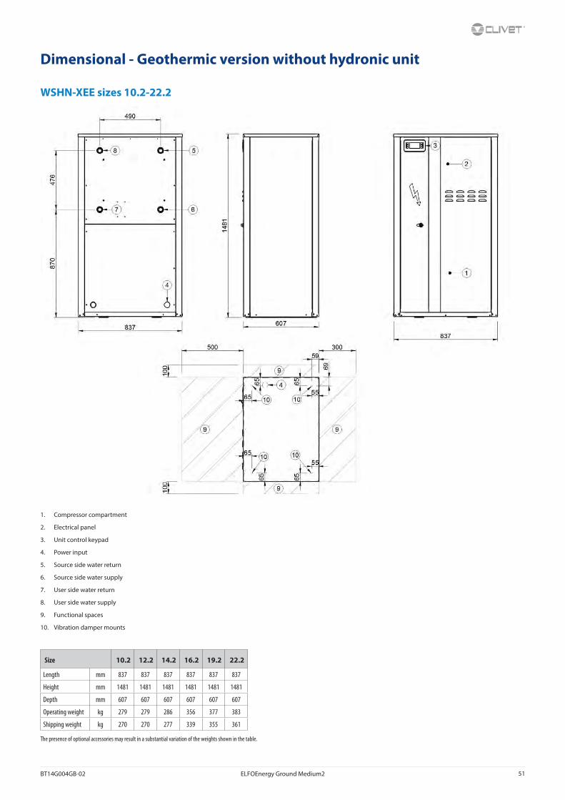
BT14G004GB-02 ELFOEnergy Ground Medium2 51
Dimensional - Geothermic version without hydronic unit
WSHN-XEE sizes 10.2-22.2
1. Compressor compartment
2. Electrical panel
3. Unit control keypad
4. Power input
5. Source side water return
6. Source side water supply
7. User side water return
8. User side water supply
9. Functional spaces
10. Vibration damper mounts
Size 10.2 12.2 14.2 16.2 19.2 22.2
Length mm 837 837 837 837 837 837
Height mm 1481 1481 1481 1481 1481 1481
Depth mm 607 607 607 607 607 607
Operating weight kg 279 279 286 356 377 383
Shipping weight kg 270 270 277 339 355 361
The presence of optional accessories may result in a substantial variation of the weights shown in the table.

52 ELFOEnergy Ground Medium2 BT14G004GB-02
Dimensional - Version with hydronic unit option and oversize enclosure (MOBMAG)
WSHN-XEE sizes 10.2-22.2
1. Compressor compartment
2. Electrical panel
3. Unit control keypad
4. Power input
5. Source side water return with pumps
6. Source side water supply
7. User side water return with pumps
8. User side water supply
9. Functional spaces
10. Vibration damper mounts
11. Source side water return without pumps
12. User side water return without pumps
Size 10.2 12.2 14.2 16.2 19.2 22.2
Length mm 837 837 837 837 837 837
Height mm 1481 1481 1481 1481 1481 1481
Depth mm 997 997 997 997 997 997
Operating weight kg 365 365 374 446 467 473
Shipping weight kg 356 356 365 429 445 451

BT14G004GB-02 ELFOEnergy Ground Medium2 53
Dimensional - Geothermic version with hydronic unit option and oversize enclosure (MOBMAG)
WSHN-XEE sizes 10.2-22.2
1. Compressor compartment
2. Electrical panel
3. Unit control keypad
4. Power input
5. Source side water return with pumps
6. Source side water supply
7. User side water return with pumps
8. User side water supply
9. Functional spaces
10. Vibration damper mounts
11. Source side water return without pumps
12. User side water return without pumps
Size 10.2 12.2 14.2 16.2 19.2 22.2
Length mm 837 837 837 837 837 837
Height mm 1481 1481 1481 1481 1481 1481
Depth mm 997 997 997 997 997 997
Operating weight kg 365 365 374 446 467 473
Shipping weight kg 356 356 365 429 445 451
The presence of optional accessories may result in a substantial variation of the weights shown in the table.
54 ELFOEnergy Ground Medium2 BT14G004GB-02
Dimensional - Standard version without hydronic unit
WSHN-XEE sizes 27.2 - 120.2
1. Compressor compartment
2. Electrical panel
3. Unit control keypad
4. Power input
5. Source side water return
6. Source side water supply
7. User side water return
8. User side water supply
9. Functional spaces
10. Vibration damper mounts
Size 27.2 30.2 35.2 40.2 43.2 45.2 50.2 55.2 60.2 70.2 80.2 90.2 100.2 120.2
Length mm 1110 1110 1110 1110 1110 1110 1110 1110 1110 1110 1110 1110 1110 1110
Height mm 1907 1907 1907 1907 1907 1907 1907 1907 1907 1907 1907 1907 1907 1907
Depth mm 1040 1040 1040 1040 1040 1040 1040 1040 1040 1040 1040 1040 1040 1040
K mm 520 520 520 520 520 520 520 520 520 520 520 520 568 568
Operating weight kg 501 506 592 670 749 687 838 861 878 995 1006 1106 1504 1666
Shipping weight kg 491 496 587 658 737 675 817 840 857 962 973 1069 1420 1572
The presence of optional accessories may result in a substantial variation of the weights shown in the table.

BT14G004GB-02 ELFOEnergy Ground Medium2 55
Dimensional - Geothermic version without hydronic unit
WSHN-XEE sizes 27.2 - 120.2
1. Compressor compartment
2. Electrical panel
3. Unit control keypad
4. Power input
5. Source side water return
6. Source side water supply
7. User side water return
8. User side water supply
9. Functional spaces
10. Vibration damper mounts
Size 27.2 30.2 35.2 40.2 43.2 45.2 50.2 55.2 60.2 70.2 80.2 90.2 100.2 120.2
Length mm 1110 1110 1110 1110 1110 1110 1110 1110 1110 1110 1110 1110 1110 1110
Height mm 1907 1907 1907 1907 1907 1907 1907 1907 1907 1907 1907 1907 1907 1907
Depth mm 1040 1040 1040 1040 1040 1040 1040 1040 1040 1040 1040 1040 1040 1040
K mm 520 520 520 520 520 520 520 520 520 520 520 520 568 568
Operating weight kg 501 506 592 670 749 687 838 861 878 995 1006 1106 1504 1666
Shipping weight kg 491 496 587 658 737 675 817 840 857 962 973 1069 1420 1572
The presence of optional accessories may result in a substantial variation of the weights shown in the table.

56 ELFOEnergy Ground Medium2 BT14G004GB-02
Dimensional - Version with hydronic unit option and oversize enclosure (MOBMAG)WSHN-XEE sizes 27.2 - 120.2
1. Compressor compartment
2. Electrical panel
3. Unit control keypad
4. Power input
5. Source side water return with pumps
6. Source side water supply
7. User side water return with pumps
8. User side water supply
9. Functional spaces
10. Vibration damper mounts
11. Source side water return without pumps
12. User side water return without pumps
13. Overall dimensions only for sizes 60.2 to 120.2 with options HYGU2 and HYGS2 (2 ON/OFF pumps)
Size 27.2 30.2 35.2 40.2 43.2 45.2 50.2 55.2 60.2 70.2 80.2 90.2 100.2 120.2
Length mm 1110 1110 1110 1110 1110 1110 1110 1110 1110 1110 1110 1110 1110 1110
Height mm 1907 1907 1907 1907 1907 1907 1907 1907 1907 1907 1907 1907 1907 1907
Depth mm 1320 1320 1320 1320 1320 1320 1320 1320 1320 1320 1320 1320 1320 1320
X mm 625 625 625 625 625 625 625 625 625 625 625 625 620 620
Y mm 520 520 520 520 520 520 520 520 520 520 520 520 568 568
Z mm 1320 1320 1320 1320 1320 1320 1320 1320 1475 1475 1475 1475 1475 1475
Operating weight kg 605 610 702 790 879 817 968 993 1012 1133 1144 1240 1642 1804
Shipping weight kg 595 600 697 778 867 805 947 972 991 1100 1111 1203 1558 1710
Z = overall dimension with HYGU2 and HYGS2 optionThe presence of optional accessories may result in a substantial variation of the weights shown in the table.

BT14G004GB-02 ELFOEnergy Ground Medium2 57
Dimensional - Geothermic version with hydronic unit option and oversize enclosure (MOBMAG)WSHN-XEE sizes 27.2 - 120.2
1. Compressor compartment
2. Electrical panel
3. Unit control keypad
4. Power input
5. Source side water return with pumps
6. Source side water supply
7. User side water return with pumps
8. User side water supply
9. Functional spaces
10. Vibration damper mounts
11. Source side water return without pumps
12. User side water return without pumps
13. Overall dimensions only for sizes 60.2 to 120.2 with options HYGU2 and HYGS2 (2 ON/OFF pumps)
Size 27.2 30.2 35.2 40.2 43.2 45.2 50.2 55.2 60.2 70.2 80.2 90.2 100.2 120.2
Length mm 1110 1110 1110 1110 1110 1110 1110 1110 1110 1110 1110 1110 1110 1110
Height mm 1907 1907 1907 1907 1907 1907 1907 1907 1907 1907 1907 1907 1907 1907
Depth mm 1320 1320 1320 1320 1320 1320 1320 1320 1320 1320 1320 1320 1320 1320
X mm 625 625 625 625 625 625 625 625 625 625 625 625 620 620
Y mm 520 520 520 520 520 520 520 520 520 520 520 520 568 568
Z mm 1320 1320 1320 1320 1320 1320 1320 1320 1475 1475 1475 1475 1475 1475
Operating weight kg 605 610 702 790 879 817 968 993 1012 1133 1144 1240 1642 1804
Shipping weight kg 595 600 697 778 867 805 947 972 991 1100 1111 1203 1558 1710
Z = overall dimension with HYGU2 and HYGS2 optionThe presence of optional accessories may result in a substantial variation of the weights shown in the table.
M08U40M14-01 WSHN-XEE2 10.2-120.2
15 Notes

WSHN-XEE2 10.2-120.2 M08U40M14-01

CLIVET SPAVia Camp Lonc 25, Z.I. Villapaiera - 32032 Feltre (BL) - Italy Tel. + 39 0439 3131 - Fax + 39 0439 313300 - [email protected]
CLIVET UK LTD (Sales)4 Kingdom Close, Segensworth East - Fareham, Hampshire - PO15 5TJ - United KingdomTel. + 44 (0) 1489 572238 - Fax + 44 (0) 1489 573033 - [email protected]
CLIVET AIRCON LTD (Service and Maintenance Division)Units F5&F6 Railway Triangle Ind Est, Walton Road - Portsmouth, Hampshire - PO6 1TG - United KingdomTel. +44 (0) 2392 381235 - Fax. +44 (0) 2392 381243 - [email protected]
CLIVET ESPAÑA COMERCIAL S.L. (Sales)Calle Gurb, 17 1º 1ª - 08500 Vic, Barcelona - EspañaTel: +34 93 8606248 - Fax +34 93 8855392 - [email protected]
CLIVET ESPAÑA S.A.U. (Service and Maintenance Division)Calle Real de Burgos Nº 12 - 28860 Paracuellos del Jarama, Madrid - EspañaTel. +34 91 6658280 - Fax +34 91 6657806 - [email protected]
CLIVET GmbHHummelsbütteler Steindamm 84, 22851 Norderstedt - GermanyTel. + 49 (0) 40 32 59 57-0 - Fax + 49 (0) 40 32 59 57-194 - [email protected]
CLIVET NEDERLAND B.V.Siliciumweg 20a, 3812 SX Amersfoort - NetherlandsTel. + 31 (0) 33 7503420 - Fax + 31 (0) 33 7503424 - [email protected]
CLIVET RUSSIA Elektrozavodskaya st. 24, office 509 - 107023, Moscow, RussiaTel. + 74956462009 - Fax + 74956462009 - [email protected]
CLIVET MIDEAST FZCODubai Silicon Oasis (DSO), High Bay Complex, Ind Unit No. 3, PO BOX 28178, Dubai, UAE Tel. + 9714 3208499 - Fax + 9714 3208216 - [email protected]
CLIVET AIRCONDITIONING SYSTEMS PRIVATE LIMITED4BA, Gundecha Onclave - Kherani Road,Saki Naka, Andheri (East) - Mumbai 400 072 - IndiaTel. +91 22 6193 7000 - Fax +91 22 6193 7001 - [email protected]
w w w . c l i v e t . c o m