installation operation maintenance - viking pump canada · pulsa 880 pumps can be installed indoors...
TRANSCRIPT

i
Bulletin #: IOM-680
Installation Operation Maintenance Instruction
IOM-880

ii
Table of Contents
1. INTRODUCTION ..................................................................................................................................... 1
1.1 How Things Work .................................................................................................................... 1
1.2 Hydraulically Balance Flat Diaphragm Design ..................................................................... 1
1.3 Reagent Head Assemblies ..................................................................................................... 2
1.4 Pump Head Assemblies .......................................................................................................... 2
1.5 Make-up Hydraulic Bypass and Bleeder Valves within the Hydraulic System ................. 2
1.6 Make-up Valve .......................................................................................................................... 2
1.7 Hydraulic Bypass Valve .......................................................................................................... 3
1.8 Pressure Relief Valve .............................................................................................................. 3
1.9 Bleeder Valve ........................................................................................................................... 3
2. INSTALLATION TIPS ............................................................................................................................... 3
2.1 Check the Shipment ................................................................................................................ 3
2.2 Locating the 880 Pumps ......................................................................................................... 3
2.3 Flooded Suction Desirable ..................................................................................................... 4
2.4 Discharge Pressure ................................................................................................................. 4
2.5 Piping ........................................................................................................................................ 4
2.6 Equipment Inspection ............................................................................................................. 4
3. STORAGE INSTRUCTIONS ...................................................................................................................... 5
3.1 Short Term ............................................................................................................................... 5
3.2 Long Term ................................................................................................................................ 5
4. INSTALLATION ...................................................................................................................................... 5
4.1 Location .................................................................................................................................... 5
4.2 Piping System .......................................................................................................................... 6
5. EQUIPMENT START UP .......................................................................................................................... 7
5.1 Lubrication ............................................................................................................................... 7
5.2 Oil Capacity .............................................................................................................................. 7

iii
5.3 Oil Change ................................................................................................................................ 8
5.4 Metal Reagent Head Models ................................................................................................... 8
5.5 Plastic Reagent Head Models ................................................................................................ 8
6. START UP INSPECTION .......................................................................................................................... 9
6.1 Filling Gear and Oil Reservoirs .............................................................................................. 9
6.2 Final Inpection ......................................................................................................................... 9
6.3 Start-Up .................................................................................................................................... 9
6.4 Priming Process Head ............................................................................................................ 9
6.5 To Adjust Flow Rate ................................................................................................................ 10
6.6 Calibration ................................................................................................................................ 11
7. OPERATION AND MAINTENANCE ........................................................................................................... 12
7.1 Diaphragm Inspection ............................................................................................................. 12
7.2 Repriming Hydraulic ............................................................................................................... 13
7.3 Piston and Diphragm Alignment ............................................................................................ 14
7.4 Check Valves ........................................................................................................................... 14
7.5 Hydraulic Make-Up Valve ........................................................................................................ 15
7.6 Hydraulic Bypass Valve .......................................................................................................... 15
7.7 Automatic Bleed Valve ............................................................................................................ 16
7.8 Lubrication Instructions ......................................................................................................... 16
7.9 Maintenance Parts Stock-KOPkits ......................................................................................... 17
7.10 Ordering Parts ......................................................................................................................... 17
7.11 Additional Pulsafeeder Services ............................................................................................ 17
8. TROUBLESHOOTING .............................................................................................................................. 18
9. APPENDEX I- SUCTION PIPING............................................................................................................ 21
10. APPENDEX II- OIL SPECIFICATIONS .................................................................................................... 23
11. APPENDEX III- PULSAFEEDER ACCESSORIES ...................................................................................... 24
7.1 PULSAtrol Installation, Operation and Removal Instructions ............................................ 24
7.2 Installation ................................................................................................................................ 24
7.3 Operation .................................................................................................................................. 25

iv
7.4 Removal .................................................................................................................................... 26
12. DIAPHRAGM BACK PRESSURE VALVES .................................................................................................. 26
Revision History: Rev A Release Date March 1993, First Release

1
1. Introduction
1.1 How it Works A standard foot mounted motor drives a worm shaft at constant speed. Through worm gear reduction and eccentric, a reciprocating power stroke is transferred to a plunger. The length of the plunger stroke determines pump capacity and can be adjusted manually to provide pumping range from 0-100% of rating. However, this plunger does not pump chemicals, but an exceptionally stable oil*, having excellent lubrication qualities. This makes a perfect pumping medium.
1.2 Hydraulically Balanced Flat Diaphragm Design (Figure 2) Using this oil, the plunger hydraulically moves a diaphragm alternately forward and backward. A displacement from this diaphragm movement in turn, takes in the liquid (chemical) being pumped through a suction check valve on the suction stroke of the plunger and discharges a like amount of liquid (chemical) through a discharge check valve on a forward or discharge stroke. The plunger operating in a sized cylinder and at exact stroke length gives exact displacement and accurate pumping rate. The diaphragm isolates the chemical being pumped within the reagent head and check valves. No other parts need to be of special chemically stable material. This isolation of prompt eliminates the possibility of contamination. The plunger handles only oil and no stuffing box is required. *A special property petroleum oil tradenamed “PULSAlube” is generally used as hydraulic fluid. Continual reference to “Oil” as hydraulic medium implies its general use rather than its use of necessity. Check with your representative or the factory if substitute oils must be used.
(Figure 2)

2
1.3 Reagent Head Assemblies (Figure 3 & 4) Flat diaphragm reagent head assemblies are available in two basic configurations. They are: Figure No. 3: Metal reagent head, plastic diaphragm Figure No. 4: Plastic reagent head, plastic diaphragm
1.4 Pump Head Assemblies
The hydraulic pump head assembly contains the plunger and various hydraulic components to protect and maintain a precise hydraulic balance between the plunger and diaphragm.
1.5 Make-Up, Bypass and Bleeder Valves within the Hydraulic System
Figure No. 2 shows the locations of the valves.
1.6 Make-Up Valve Any leakage past the plunger or bleeder, however slight, is replaced by the make-up valve which permits flow of replacement oil from the oil reservoir. This is an automatic function because the oil loss allows the diaphragm to get out of phase with the plunger thus creating a vacuum ahead of the plunger during the suction stroke. The make-up valves are factory set.

3
1.7 Hydraulic Bypass Valve Any excess hydraulic pressure buildup within the pump compression chamber or chemical end due to accidental valve closure or line stoppage is relieved through the hydraulic bypass valve. It blows off oil under excess pressure ahead of the plunger back into the oil reservoir thus terminating the pumping action and protecting the pump mechanism. Hydraulic bypass valves are factory set at full design pressure unless specified differently by purchaser.
1.8 Pressure Relief Valve
A separate process relief valve should be installed in the process piping to protect piping and sensitive process equipment.
1.9 Bleeder Valve
The function of this valve is to release any air or oil vapors from ahead of the piston and maintain a solid hydraulic medium to transmit infinite movements of the piston to the diaphragm. The bleed valve functions automatically weeping a minute quantity of oil plus any air or vapor out of the hydraulic system. Additional detail on the function of these valves will be given as applicable in the Operation, Maintenance and Troubleshooting Sections.
2. Installation Tips
2.1 Check the Shipment
A standard Pulsafeeder shipment includes the pump, PULSAlube oil, wrenches, instruction and parts list packet as well as replacement parts if ordered. Unpack carefully, check packing list and make sure all parts are received. Check voltage of electric motor against the service to be used.
2.2 Locating the 880 Pumps Pulsa 880 pumps can be installed indoors or outdoors. For outdoor installation be sure you purchased a pump with proper hydraulic oil for the lowest temperature condition you will experience. PULSAlube #1 has an effective temperature range of 40◦F to 280◦F (4.4◦C to 137.8◦C). For adverse conditions, -40◦F to +400◦F (-40◦C to 204◦C) PULSAlube #5 must be used. 1. Check level of pump. Shim where necessary. 2. Securely bolt to foundation. Do not distort base. 3. Check motor alignment, reagent head, and valve bolt tightness before operation. Follow bolt
torque readings carefully.

4
2.3 Flooded Suction Desirable Installation will be simpler to operate if the liquid will flow to the pump by gravity. Wherever possible, the pump should be located below the level of storage vessel.
2.4 Discharge Pressure
All 880 models are designed for continuous service at the rated discharge pressure. To prevent liquid flow through, it is necessary that discharge pressure be at least 5 psi above suction pressure. When pumping downhill, a back pressure valve should be placed in the discharge line.
2.5 Piping
Pipe size and length are critical to proper operation of any metering pump. A restricted discharge or starved suction condition spells immediate failure to any metering pump installation. A separate brochure entitled “Designing a Successful Metering Pump Installation” is provided to assist engineers responsible for piping system design. Copies are available upon request (Technical Sheet 304). Inlet piping must be at least equal in size to pump inlet connection. MINIMUM INLET PIPING CONDITIONS MUST BE CALCULATED USING THE FORMULAS FOUND ON PAGE 18.
2.6 Equipment Inspection
Check all equipment for completeness against the order and for any evidence of shipping damage. Shortages or damage should be reported immediately to the carrier and to your PULSA Series representative.

5
3. Storage Instructions
3.1 Short Term
Storage of PULSA Series pumps for up to 12 months after shipment is considered short term. Under this condition the recommended storage procedures are as follows: 1. The pump should be stored indoors at room temperature in a dry environment. 2. The stroke setting should be positioned for minimal stroke setting or at zero setting. 3. The pump gearbox and hydraulic reservoir is to be completely filled with PULSAlube oil within two
months after date of shipment. 4. The gearbox and hydraulic reservoir should be inspected ever 3-6 months. Maintain the oil level and
assure that no water or condensation is present, follow Procedure II, Step A below. 5. It is recommended that the stroke length of the pump be adjusted to its midpoint and that the piston
be manually cycled through 3-6 cycles every six months. 6. Prior to start-up, perform a complete inspection and then start up in accordance with instructions in
this manual.
3.2 Long Term
For storage longer than 12 months in addition to the above, the following procedures should be followed. 1. Every 12 months PULSAlube oil should be drained from the gearbox and hydraulic reservoir. The
gearbox and the hydraulic reservoir should be flushed with kerosene or petroleum base solvent, thoroughly dried out with a rag, and then refilled with fresh PULSAlube oil.
2. Every 12 months the motor should be connected to a power source and the pump operated for a minimum of one hour. It is not necessary to have liquid in the reagent head during this operation but the suction and discharge ports must be open to the atmosphere.
After 12 months storage, Pulsafeeder’s warranty cannot cover such items as oil seals, gaskets, piston cups, and other items which are subject to deterioration with age. If the pump has been in storage for longer than 12 months, it is recommended that these items be replaced prior to going into service. Material and labor to recondition or replace this class of item is the purchaser’s responsibility. For a one year service warranty after extended storage, the refurbishment and equipment inspection must be done by a Pulsafeeder serviceman.
4. Installation
4.1 Location
When selecting an installation site, or designing a skid package, consideration should be given to access in order to perform routine maintenance. PULSA Series pumps are designed to operate indoors or outdoors but it is desirable to provide a hood or covering for outdoor service. Alternate oil or external heating is required if ambient temperature will be below 40◦F (4.4◦C). check with the factory if concerned with the suitability of the operating environment. The pump must be rigidly bolted to a solid and flat foundation to minimize vibration. Vibration can loosen gaskets and pipe connections. When the pump is bolted down care must be taken to avoid

6
distorting the base and affecting alignments. This is especially important for multiplex units. The pump must be level within 2◦. This will assure that the oil in the gearbox is maintained at the correct level and that the check valves can operate properly.
4.2 Piping System Figure 5 shows the preferred piping configuration for a good metering pump installation. Custom head assemblies require special piping arrangements, refer to separate instructions. Regardless of the arrangement required, all piping systems should include the following:
A. Shut off valve sand unions (or flanges) on the suction and discharge piping. This allows routine inspection of the check valves without draining long runs of piping. The shut off valves should open to full pipe line diameter. Ball valves are preferred (do not use needle valves).
B. An inlet strainer if the product is not slurry. Pump check valves are susceptible to dirt and other contaminates unless designed for that service. Any accumulation can cause a malfunction. The strainer should be placed between the suction shut-off valve and the pump suction valve. The sizing must accommodate the flow rate and expected contamination, one hundred mesh screen is generally used.
C. Hangers and straps to support piping. Do not allow the weight of piping to be supported by the valve housings or other portion of the reagent head, or leaks will occur. Where necessary, provide for thermal expansion and contraction so that no strain is placed on the pump.

7
D. Vacuum/pressure gauges in the suction and discharge lines are recommended in order to check system operation. All gauges should incorporate shut-off valves to isolate them when they are not being monitored.|
E. In addition, a separate process relief valve should be installed in the process piping to protect piping and sensitive process equipment. In assembly of piping, use pipe thread tape or similar compound compatible with the product being handled. Whether new or existing piping is used, all lines should be flushed with a clean liquid and blown out with air before making final connections to the pump. Ensure that the flushing liquid is compatible with the liquid to be pumped.
5. Equipment Start Up
5.1 Lubrication Every PULSA Series metering pump is tested at full capacity and operating pressure before shipment. However, for shipping purposes the gearbox and hydraulic reservoir oil has been removed. Fresh oil is included in separate container(s).
WARNING 1. DO NOT run pump without oil. 2. DO NOT remove main gear box cover while pump is running. 3. DO NOT run pump with coupling guard removed. 4. DO NOT put hands or fingers in gear box or reservoir when pump is running.
5.2 Oil Capacity All PULSAlube oils are available in: 1 Quart Containers 1 Gallon containers 5 Gallon containers 55 Gallon Drums It is recommended that an adequate supply of PULSAlube be on hand to handle periodic oil changes and emergency requirements. The amount of oil required to fill PULSA Series 880 gearboxes are 1.5 quarts.
8
5.3 Oil Change The recommended oil change interval is dependent upon the operating environment, two classifications are used. 1. Normal Service: Clean/Dry atmosphere and a gearbox operating temperature of 40◦F to 100◦F
(4.4◦C to 37.7◦C).
2. Severe Service: Humid atmosphere and a gearbox operating temperature below 40◦F to over 100◦F (4.4◦C to 37.7◦C).
The first oil change should be done after 6 months of continuous operation (approximately 4500 hours) and then every 12 months (9000 hours) for normal service and every 6 months (4500 hours) for severe service. Follow the procedure below when changing the oil.
1. Remove all pressure from the reagent head. 2. Disconnect power to the motor. 3. Remove the motor coupling guard. 4. Set the pump stroke to 0%. 5. Remove cover from the pump. 6. On the side of the pump at the bottom of each reservoir is a pipe plug, remove these to drain the oil.
Note, on some models an oil return tube may be piped to the drain hole, remove the tube and fitting to drain the reservoir. It is not necessary to drain the oil in the hydraulic system including any piping to remote heads unless the system has been contaminated due to a diaphragm failure.
7. Wash down the inside of the gearbox with kerosene for a petroleum base solvent. It may be helpful to rotate the motor coupling by hand in order to reach all areas of the box.
8. Flush the box and remove all traces of solvent by drying out the box with a rag. Replace the pipe plugs and/or fittings.
9. Refill both reservoirs with fresh PULSAlube oil. The level should be ½” to ¾” from the top of each reservoir.
5.4 Metal Reagent Head Models:
The metal reagent head assembly is provided in several alloys. Piping of similar alloy should be selected. Dissimilar materials can cause galvanic corrosion. Do not backweld piping to the valve housings without first removing the valve housing from the pump as excessive heat can damage the reagent head and other parts. Tie bars must be positioned on the valve housing before welding.
5.5 Plastic Reagent Head Models: Care must be exercised when making connections on plastic reagent head models. Excessive tightening
can distort or break the plastic materials. Tubing should be rated for the highest discharge pressure expected.

9
6. Start-Up Inspection Every 880 metering pump is tested for correct capacity at maximum pressure capability of the hydraulic bypass valve before shipment. The diaphragm cavity is fully primed and remains so for shipment. For shipping purposes, the gear and hydraulic reservoir oil have been removed. Sufficient fresh PULSAlube oil is included with the shipment for refilling the gear and hydraulic reservoirs.
WARNING 5. DO NOT run pump without oil. 6. DO NOT remove main gear box cover while pump is running. 7. DO NOT run pump with coupling guard removed. 8. DO NOT put hands or fingers in gear box or reservoir when pump is running.
6.1 Filling Gear and Oil Reservoirs Remove the pump cover and fill both reservoirs with PULSAlube oil to the top of the gear box partition. Do not overfill. PULSAlube oil is compounded to serve as both gear lubricant and hydraulic transfer fluid. Check with factory if substitute oils must be used. The cover assembly incorporates a free acting diaphragm to allow breathing of the reservoir and at the same time seal the reservoir from the atmosphere. Be sure the diaphragm is properly positioned when replacing the cover so that it will seal on the cover.
6.2 Final Inspection
Because of the pump’s small size and light weight it sometimes receives severe handling during shipment. Though physical damage may not occur, it is always possible for parts to move slightly in adjustment. This situation might occur with motor or pneumatic control alignment. A quick visual check should be made to assure that motor and control shafts have not shifted severely out of alignment or damage could occur from starting the motor. If unusual vibration should occur after start up, realign the motor and coupling.
6.3 Start-up
Since the hydraulic oil system is primed at the factory, priming the process system is all that should be necessary to produce flow. If the hydraulic system has inadvertently been dumped due to start up with restricted suction or discharge conditions or improper adjustments to compensator or bleed valves, repriming procedures under the maintenance section may have to be followed before pump calibration can begin.
6.4 Priming Process Head 1. Open the suction line and discharge line shut off valves. 2. If the piping system design and the storage tank are such that the product flows by gravity to
the pump, no priming is required. If however, the discharge line is under pressure, air will be trapped in the process head and it will be necessary to remove the discharge pressure to enable the pump to prime itself.
10
3. If the pump must handle a suction lift, it may be necessary to manually prime the reagent head. Remove the discharge valve by unscrewing the two tie bar bolts and then lifting the valve out. Fill the head with process fluid, or a compatible liquid, then replace the valve in the same position and retighten the tie bar bolts.
4. The pump is now ready for start-up. 5. Start the pump and increase the control setting to full stroke. 6. Make a brief check to assure that the pump is producing the approximate flow desired at the
full stroke setting. Calibration should not be attempted on any model until it has run at least one hour to assure the pump hydraulic and reagent head systems have stabilized.
If the pump does not produce the approximate flow desired at the full stroke setting refer the Trouble
Shooting Section for possible causes and refer to the Priming Procedure under the Operation and Maintenance Section.
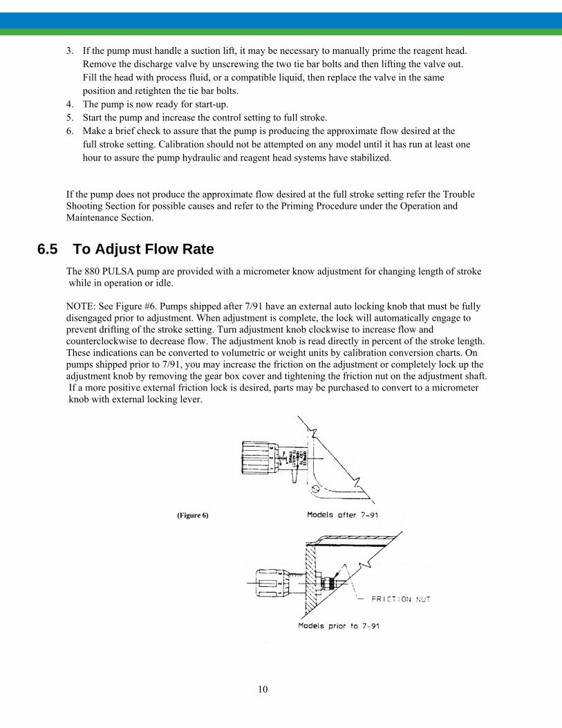
6.5 To Adjust Flow Rate The 880 PULSA pump are provided with a micrometer know adjustment for changing length of stroke while in operation or idle. NOTE: See Figure #6. Pumps shipped after 7/91 have an external auto locking knob that must be fully
disengaged prior to adjustment. When adjustment is complete, the lock will automatically engage to prevent drifting of the stroke setting. Turn adjustment knob clockwise to increase flow and counterclockwise to decrease flow. The adjustment knob is read directly in percent of the stroke length. These indications can be converted to volumetric or weight units by calibration conversion charts. On pumps shipped prior to 7/91, you may increase the friction on the adjustment or completely lock up the adjustment knob by removing the gear box cover and tightening the friction nut on the adjustment shaft.
If a more positive external friction lock is desired, parts may be purchased to convert to a micrometer knob with external locking lever.
(Figure 6)
11
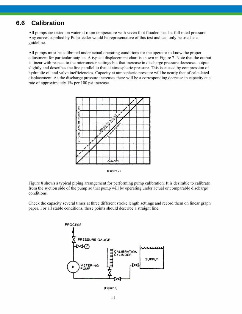
6.6 Calibration All pumps are tested on water at room temperature with seven foot flooded head at full rated pressure. Any curves supplied by Pulsafeeder would be representative of this test and can only be used as a guideline. All pumps must be calibrated under actual operating conditions for the operator to know the proper adjustment for particular outputs. A typical displacement chart is shown in Figure 7. Note that the output is linear with respect to the micrometer settings but that increase in discharge pressure decreases output slightly and describes the line parallel to that at atmospheric pressure. This is caused by compression of hydraulic oil and valve inefficiencies. Capacity at atmospheric pressure will be nearly that of calculated displacement. As the discharge pressure increases there will be a corresponding decrease in capacity at a rate of approximately 1% per 100 psi increase.
Figure 8 shows a typical piping arrangement for performing pump calibration. It is desirable to calibrate from the suction side of the pump so that pump will be operating under actual or comparable discharge conditions. Check the capacity several times at three different stroke length settings and record them on linear graph paper. For all stable conditions, these points should describe a straight line.
(Figure 7)
(Figure 8)

12
PULSA pumps are supplied with automatic controls, either pneumatic or electronic, are accompanied by separate instructions on output adjustment and calibration. Make all required connections prior to performing start up procedure.
7. Operation and Maintenance The preceding instructions have assisted you in proper installation and start-up of your 880 pump. The following sections are arranged to assist in maintaining proper pump operation and troubleshooting any problems that might develop during start-up or thereafter. Accurate records in the early stages of pump operation will reveal the type and amount of maintenance that will be required. A preventative maintenance program based on these records will insure trouble free operation. It is not possible in these instructions to forecast the life of such parts as the diaphragm, check valves and other parts in contact with the product you are handling. Corrosion rates and conditions of operation affect the useful life of these materials so an individual metering pump must e gauged according to particular service conditions.
7.1 Diaphragm Inspection (Figure 9) Pulsafeeder TFE plastic or metal diaphragms are not subject to stress fatigue and do not fail from repeated flexure. However, long-time accumulation of foreign material or entrapment of hard, sharp particles between the diaphragm and the dish cavity can eventually cause premature damage. Periodic inspection of the diaphragm is desirable, especially if the product pumped carries large particles or trash. To remove the diaphragm, the first four steps are the same for plastic and metal diaphragms. 1. Remove all pressure from the piping system. 2. Close the inlet and outlet shut-off valves. 3. Break the union or flanges on the piping. 4. Arrange to catch and properly dispose of the oil and product leakage that will occur when
disassembling head and valving. 5. Remove the inlet check valve to drain reagent head and cavity. Use extreme caution if product is
hazardous and wear proper protective clothing. For plastic diaphragms, follow Steps 6 through 10. For metal, follow Steps 11 through 15. 6. Remove reagent head bolts and rinse the head in water or a compatible liquid.
(Figure 9)

13
7. Flat disc style diaphragms in TFE material which remain attached to the reagent head can be removed undamaged by forcing compressed air into the inlet port while plugging the discharge port. Diaphragms which remain attached to the hydraulic pump head can be removed undamaged by rotating the piston by hand.
8. If the diaphragm shows no evidence of damage, there is no need to replace it. A slight warped condition is normal and will not require replacement of the diaphragm.
9. On models which have an insert dish plate, make sure the dish plate is reset in the pump head with the cavity on the diaphragm side and one of the four holes closest to the outer edge positioned at the top to permit air to bleed out of the cavity when priming.
10. Some Pulsafeeder plastic diaphragms incorporate an integral “O” ring design. Follow torque restriction in table on the following page. Simply tighten to bolt strength limit. On other models, where there is no “O” ring, the diaphragm must be compressed to form a seal. Be careful to follow the torque limits in the table (page 10). MODELS WITH PLASTIC HEAD AND VALVES MUST BE TIGHTENED BY HAND ONLY TO AVOID DISTORTION OF PARTS.
The following steps apply to metal diaphragms:
11. As the diaphragm is sealed by “O” rings, or gaskets, at bolt the pump head and reagent head, leakage of both oil and product pumped can occur simultaneously when the reagent head bolts are loosened. It is, therefore, desirable to remove the inlet check valve to drain the reagent head and cavity. Proceed with care if the product is hazardous.
12. When removing the reagent head bolts, leave two bottom bolts in place but back them out until the diaphragm is exposed at the top. Pick out the diaphragm with needle nose pliers.
13. If the diaphragm shows damage, replace it. 14. If the “O” rings are extruded or cut, replace them. On models with flat gaskets, replace the gaskets
each time the head is removed. Make sure gaskets are properly centered on serrations located on the pump and reagent head. Hold the gaskets in place with an adhesive. DO NOT COMPLETELY COAT THE GASKETS AS THIS WILL FILL SERRATIONS WITH COMPUND AND IMPAIR SEALING.
15. Before reassembly, make sure all faces of the reagent head and pump are clean. 16. Before mounting the reagent head, make sure the pump head dish plate is seated in the head with the
concave cavity facing the diaphragm, and one of the four holes closest to the edge of the dish plate is at the top of the pump head. This assures that any gases are vented out of the dish cavity.
17. Reinstall the reagent head bolts and tighten in an alternating pattern to ensure an even seating force. 18. Refer to the Torque Table for recommended torque values.
7.2 Repriming Hydraulic
1. Reassemble diaphragm and reagent head, tightening all bolts securely and evenly. Use reliable torque wrench to valves indicated.
2. Reassemble valve housing and take care in inserting gaskets that they are properly positioned. Replace valves, seats and seat gaskets incorrect orientation for direction of flow (see Figure 10-13) and tighten securely.
3. Connect inlet piping. 4. With discharge line bypassed around process or to drain, start motor and prime reagent head. 5. Set stroke length adjustment to maximum stroke. 6. Stop the pump and remove the manual bleed/auto bleed valve assembly from pump head. 7. Place a plastic pipette (i.e. turkey baster) in the manual bleed/auto bleed valve hole of the pump
head. Fill pipette with oil being used in gearbox. 8. Start the pump. As the pump operates each suction stroke of the pump will draw in oil from pipette
and each discharge stroke will expel air from the pump head. 9. Add oil to pipette as necessary until no more air is expelled from the pump head and oil is moving
up and down pipette with piston movement.

14
10. Shut down the pump and manually retract the piston to full rearward position. (This may be done by removing coupling cover and manually turning motor shaft.)
11. Remove the pipette and replace the manual bleed/auto bleed valve assembly.
7.3 Piston and Diaphragm Alignment
12. Manually rotate motor shaft until piston is in full forward position. 13. If piston does not set up before full forward position is obtained then pump piston and diaphragm is
phased. 14. If piston set up at some point prior to achieving full forward position then loosen up bypass valve
setting (keeping track of the number of turns) until piston slips forward forcing excess oil from the pump head through the bypass valve. Move piston to full forward position.
15. Retighten bypass valve to previous setting, but do not exceed MAX OPERATING PRESSURE indicated on pump nameplate.
16. Hydraulics is primed and piston is phased with diaphragm.
7.4 Check Valves (Figure 10, 11, 12 & 13)
Operating experience on thousands of installations has indicated the many metering pump troubles have to do with check valves. Problems usually stem from (a) an accumulation of trash between the valve and seat, (b) corrosion which damages seating surfaces, (c) erosion from high velocity flow, or (d) normal physical damage after extended service. When reassembling after cleaning or replacement be sure to use new seals. A valve seat, to function correctly, must have a polished, arrow seating surface. If the valve seats do not show serious wear, it is sometimes possible to rework on a precision lathe. The knife-like edge at the seat surface can be peened. Place a ball of the same size but of harder metal onto the seat. Then tap the ball using a brass rod and hammer. A single sharp blow is usually sufficient.
(Figure 10) (Figure 11) (Figure 12) (Figure 13)

15
7.5 Hydraulic Make-up Valve Hydraulic make-up valves are designed to maintain the correct volume of oil in the hydraulic system between the piston and the diaphragm. No adjustment or attention is required, provided the oil is clean and free of moisture and chemical contamination. Since the valve operates only occasionally and with very little movement, it is not considered a normal replacement item in a service schedule. If the valve is replaced because of corrosion or fouling, be sure tape or sealant is used on the pipe threads to assure an air tight seal.
7.6 Hydraulic Bypass Valve
The hydraulic bypass valve is an adjustable spring loaded valve. It is designed to protect the pump against excessive hydraulic pressure. The valve is factory set to the setting specified on the specification data sheet or set to allow operation at the maximum pump pressure, indicated on the pump nameplate, without weeping. To adjust the valve to a lower relief pressure, turn counter-clockwise. To check the pressure setting it is necessary to install a gauge in the discharge line between the pump and a shut off valve. With the pump operating at maximum stroke, a gradual closing of the shut off valve will cause the bypass valve to reach its cracking pressure which will be observed on the gauge. When the bypass valve is set for maximum pump operating pressure (shown on nameplate), cracking pressure is slightly above maximum operating pressure so that it does not weep during normal pump operation. Dead head dumping pressure can be considerably higher than cracking pressure on some large piston, fast stroke rate models, so the internal bypass valve should not be considered a safety valve for protection of the process piping and instrumentation. A separate process relief valve should be used for this purpose. It is unusual for a hydraulic bypass valve to operate during normal pump operation. The following conditions will cause bypass pump operation. 1. Excessive pressure buildup in the process which the pump is injecting into. 2. A plugged discharge line or someone shutting off a valve in the discharge line while the pump is
operating. 3. Restricted flow to the pump causing the make-up valve to operate. If an inlet strainer is plugged, or
someone closes an inlet valve thereby restricting the flow of fluid to the pump, the diaphragm is then unable to follow movement of the plunger. The vacuum created between the diaphragm and the plunger upset the make-up valve allowing oil to replace the vacuum condition. This excess oil will be displaced through the bypass valve on the discharge stroke of the plunger. Undersized (restrictive) piping must be avoided (see “Piping” page 5.) Any unusual condition in the system which prevents free movement of the diaphragm will cause a recirculating condition between the make-up valve and the hydraulic bypass valve. Continuous oil recirculation against the bypass valve will eventually cavitate the hydraulic prime plus introduce unnecessary load conditions within the pump mechanism.

16
7.7 Automatic Bleed Valve (Figure 14) The automatic bleed valve is a gravity operated ball check valve designed to displace a small quantity of hydraulic oil or air on each pump stroke. Any accumulation of solids can cause malfunction. Unscrew the valve and clean it with kerosene or solvent. If solids cannot be removed, the valve must be replaced since there is no means of repair.
7.8 Lubrication Instructions PULSAlube is a custom blend oil with additives for lubrication and hydraulic transfer service. (For emergency requirements, a list of acceptable commercial oils is available). The diaphragm on the cover of the gearbox assembly generally protects the oil from contamination for extended periods of time. A periodic six month check should be made for oil level and possible contamination. Under sustained conditions of high humidity or if water is present, the oil can become emulsified and take on a yellowish color. Change the oil immediately if this occurs and examine the make-up valve and other parts for corrosion. A suction pump similar to a grease gun is useful for removing oil from the chambers, or it may be drained from the ports at the side of each chamber. To establish a maintenance record and routine procedure, check lubricant and drive mechanism at three and six month intervals. At the first six month interval, check the condition of the inlet and out let check valves. These items along with the oil seal inspection should be part of a routine service procedure.
(Figure 14)

17
7.9 Maintenance Parts Stock- KOPkits® Pulsafeeder offers a KOPkit which is a group of recommended spares carried in stock for replacement due to normal wear. The Kit covers such items as diaphragm, diaphragm gaskets if used, inlet and discharge valve parts, a complete set of valve gaskets and hydraulic pump head gasket. The KOPkit part number for your pump is indicated don the nameplate. A sufficient quantity of PULSAlube oil should be on hand for periodic oil changes.
7.10 Ordering Parts
When ordering parts, always specify: 1. Pump model and serial number (stamped on nameplate). 2. Part number (from parts list), or KOPkit number. 3. Material of reagent head construction (liquid end parts).
7.11 Additional Pulsafeeder Services FIELD SERVICE: Including pump repair or conversion to different services is available at nominal cost. FACTORY REPAIR: Complete pump reconditioning OPERATOR TRAINING SEMINARS: Conducted by experienced factory trained service personnel at the factory in Rochester, NY or in the field. Field trips are available at nominal cost.
(Figure 15)

18
8. Troubleshooting Experience drawn from thousands of installations has shown that there are three outstanding areas which contribute to the bulk of operating problems. First and foremost is the installation conditions-improper location and supply, inadequate or restrictive piping to and from the pump; unsupported piping; lack of strainer in suction piping. The second major area is check valves. The check valve is the heart of any pump and sees more severe service than any other part of the pump. Opening and closing 58 to 175 times per minute and the valve not only receives a mechanical hammering but receives it under high velocity, corrosive, erosive and sometimes extreme temperature conditions. Foreign particles unlevel mounting, defective seals and improper torquing all too often aggravate even the simplest application. The third area is a simple lack of a routine service policy. Routine service will catch or avoid simple operating problems which can develop into a crisis if left unattended. The following is a brief troubleshooting guide to help identify and cure any operating problems you might experience.
Difficulty Probable Cause Remedy
Pump does not start 1. Coupling disconnected. 2. Faulty power source 3. Blown fuse, circuit breaker 4. Broken wire 5. Wired improperly.
1. Connect and align 2. Check power source. 3. Replace-locate overload. 4. Locate and repair. 5. Check diagram.
No Delivery
1. Motor not running.
2. Supply tank empty. 3. Lines clogged. 4. Closed lined valves. 5. Ball check valves held open with
solids. 6. Vapor lock, cavitation. 7. Prime lost. 8. Strainer clogged. 9. Hydraulic system under-primed.
10. Check valves installed upside down.
1. Check power source. | Check wiring diagram.
2. Fill with liquid. 3. Clean and flush 4. Open pipeline valves. 5. Clean-inspect.
6. Increase suction pressure. 7. Reprime, check for leaks 8. Remove and clean. 9. Refer to “Repriming
Hydraulic System”. 10. See check valve illustrations.
Low Delivery 1. Motor Speed too low.
2. Check valves worn or dirty. 3. Hydraulic Bypass valve opening
each stroke.
1. Check voltages, hertz, wiring, and terminal connections. Check nameplate vs. specifications.
2. Clean, replace if damaged. 3. Refer to “Hydraulic Bypass Valve” 4. Evaluate and correct.

19
4. Calibration system error. 5. Product viscosity too high. 6. Product cavitating.
5. Lower viscosity by increasing product temperature. Increase pump size.
6. Increase suction pressure. Cool product as necessary.
Delivery Gradually Drops
1. Stroke adjustment creeping.
2. Check valve leakage. 3. Leak in suction line. 4. Fouled bypass or make-up valve.
5. Strainer fouled. 6. Product change. 7. Bypass leakage.
1. Consult factory. Replace worn parts.
2. Clean, replace if damaged. 3. Locate and correct. 4. Refer to “Operation and
Maintenance”. 5. Clean or replace screen. 6. Check viscosity. 7. Correct for bypass valve leakage.
Difficulty Probable Cause Remedy
Delivery Erratic 1. Leak in suction line. 2. Product cavitating. 3. Entrained air or gas in product. 4. Motor speed erratic. 5. Fouled check valves.
1. Locate and correct. 2. Increase suction pressure. 3. Consult factory for suggested
venting. 4. Check voltage, hertz. 5. Clean, replace if necessary.
Delivery Higher Than Rated
1. Suction pressure higher than discharge pressure.
2. Discharge piping too small.
3. Back pressure valve set too low. 4. Back pressure valve leaks.
1. Install back pressure valve or consult factory for piping recommendations.
2. Increase pipe size-install PULSAtrol pulsation dampener at pump in discharge line.
3. Increase setting. 4. Repair, clean, or replace.
Pump Loses Oil 1. Diaphragm ruptured. 2. Leaky oil seal. 3. Cover gasket leaks. 4. Pump head gasket leaks.
5. Gear box overfilled.
1. Replace. 2. Replace. 3. Replace or tighten. 4. Replace. Tighten pump head bolts.
Seal with permatex. 5. Remove excess oil.
Air Continuously Bleeds From Automated Air Bleed Valve
1. Oil in reservoir low. 2. Hydraulic bypass valve opening
continuously. 3. Suction pressure too low. 4. Breakdown of oil, temperature high.
1. Refill to correct level. 2. Refer to “Hydraulic Bypass Valve”.
3. Increase pressure. 4. Change oil type, consult factory.

20
Noisy Gearing, Knocking
1. Discharge pressure too high. 2. Water hammer. 3. Worn bearings. 4. Worn gears. 5. End play in worm shaft. 6. Eccentric or worm gear. 7. Bypass valve set too high.
1. Reduce pressure or discharge piping size.
2. Install PULSAtrol. 3. Replace. 4. Replace gears & check for improper
hydraulic bypass valve setting. 5. Consult factory. 6. Tighten or replace assembly. 7. Readjust (see “Hydraulic bypass
Valve”.
Difficulty Probable Cause Remedy
Piping Noisy 1. Pipe size too small.
2. Pipe runs too long. 3. Surge chambers full of liquid.
4. No surge chambers used.
1. Increase size of piping, install PULSAtrol.
2. Install PULSAtrol in line. 3. Recharge with air or inert gas,
replace diaphragm and recharge 4. Install PULSAtrols-pulsation
dampeners
Motor Overheats pump design
1. Pump overloaded 2. Oil too viscous 3. Low voltage 4. Loose wire
1. Check operating conditions against 2. Consult factory 3. Check power supply 4. Trace and correct. Check no load
amps.

21
9. APPENDIX I- Suction Piping All PULSA Series pumps have a Minimum Suction Head requirement, MSHr for proper operation of the hydraulic system. Use Formula #1 or #2 (depending upon viscosity) to determine the MSHa (available) to meet the MSHr. FORMULA #1 (if liquid is over 50 centipoise, use FORMULA #2).
MSHa = Pa + Ph - [ ] (psia)
FORMULA #2
MSHa = Pa + Ph - √[ ] + [ ] (psia)
The answer to Formula #1 and #2 must be:
- At least 9.5 psia for Disc and Hydratube diaphragm - At least 6.0 psia for Hydracone diaphragm
In addition to meeting MSH r of the hydraulic system, the Net Positive Suction Head available NPSHa , must be 5.0 psi or greater. Use Formula #3 or #4 (depending on viscosity to determine NPSHa.
FORMULA #3 (if liquid is over 50 centipoise, use FORMULA #4).
NPSHa = Pa + Ph – Pv - [ ] (psi)
FORMULA #4
NPSHa = Pa + Ph – Pv - √[ ] + [ ] (psi)
If the answer to FORMULA #1 or #2 is at least 9.5 and the answer to FORMULA #3 or #4 is at least 5, then the operating conditions are satisfied.
LRVG 525
LRVG 525
2 LVC 980d2
2
LRVG 525
LRVG 525
2 2LVC 980d2

22
Where: Pa = Atmospheric pressure or pressure above liquid (psia) + Ph = Head of liquid above or below pump center line (psi) Pv = Vapor pressure of liquid at pump inlet (psia) L = Length of pipe in feet R = Pump strokes/minute V = Velocity in ft./sec V = Q
45.9 (d2) G = Specific gravity of liquid C =Viscosity (in centipoise) d =Internal pipe diameter in inches Pt = Pressure total (psia) Pp = Presure at point of discharge (psia) Q = Gallons per hour
TORQUE TABLE
REAGENT HEAD HEAD BOLT TORQUE FT/LBS TIE BAR TORQUE IN/LBS. W203344 21.7 50.7 W201544 5.8 12.2 W201983 11.3 29.7
Do not use these torque ratings for models with plastic reagent head or valve housings. Bolts on these models should only be hand tightened for adequate seal.

23
10. APPENDIX II- Oil Specifications PULSAlube #1 For service +40°F (4°C) to +280°F (137°C) Typical Characteristics:
Appearance: Clear and bright Physical Form: Liquid
Odor: Petroleum Odor Threshold: No data
pH: Not applicable Vapor Pressure: <1 mm Hg Vapor Density (air = 1): >1 Boiling Point/Range: No data Melting/Freezing Point: <10.4°F/ <-12°C
Pour Point: <10.4°F/ <-12°C Solubility in water: Negligible Partition Coefficient (n-octanol/water) (Kow): No data Specific Gravity: 0.86 – 0.90 @ 60°F (15.6°C) Bulk Density: 7.1 – 7.5 lbs/gal Viscosity: 5-32 cSt @ 100°C; 30-500 cSt @ 40°C Percent Volatile: Negligible Evaporation Rate (nBuAc=1): No data Flash Point: > 302°F / >150°C Test Method: Pensky-Martens Closed Cup (PMCC), ASTM D93, EPA 1010 LEL (vol % in air): No data UEL (vol % in air): No data Auto ignition Temperature: No data PULSAlube #5 For service -40°F (-40°C) to +400°F (204°C) Typical Characteristics:
Appearance: Liquid Color: Orange Odor: Mild Odor Threshold-ppm: NE pH: NA Boiling Point C(F): >316(600) Melting Point C (F): NA Flash Point C (F): >210 (410) (ASTM D-93) Flammability (Solids): NE Auto Flammability C(F): NA Explosive Properties: NA Oxidizing Properties: NA Vapor pressure-mmHg 20 c: < 0.1 Vapor Density: >2.0 Evaporation Rate: NE Relative Density, 15/4 C: 0.86-1 Solubility in Water: Negligible Partition Coefficient: >3.5 Viscosity at 40C, cSt: >20.0 Viscosity at 100 C, cSt: NE Pour Point C(F): NE Freezing Point C(F): NE Volatile Organic Compound: NE DMSO Extract, IP-346 (WT. %): <3, for mineral oil only NA= Not Applicable NE= Not Established D=Decomposes

24
11. APPENDIX III- Pulsafeeder Accessories
11.1 PULSAtrol Installation, Operation and Removal Instructions The PULSAtrol is a pneumatically charged diaphragm type chamber that continuously stores energy. Used on the inlet, it will improve NPSHa (Net Postiive Suction Head available) characteristics of the suction piping system. On the discharge line, it will reduce dangerous Peak pressures, eliminate shock waves and if of sufficient volume, will reduce pulsation flow to almost linear.
11.2 Installation (Figure 16 a and b) On both discharge and suction lines it is desirable to mount the PULSAtrol as close to the pump connection as possible. It can be mounted in any position, but vertical is preferred for ease of charging, draining and servicing. The air chamber is sealed and will not require replenishing regardless of position. A shut off valve should always be used between the piping system and PULSAtrol; also a drain valve should always be installed directly below the PULSAtrol. If the discharge line is open to atmospheric pressure then a back pressure valve should also be incorporated in the system near the PULSAtrol to assure proper operation.

25
11.3 Operation (Charging the PULSAtrol) Discharge Installation: The air side of the PULSAtrol must be precharged to approximately 50 percent of anticipated mean line pressure before placing on stream. This will permit the diaphragm to move to a neutral position between the chambers when operating.
PROCEDURE: Pre-Charge Procedure for Discharge Installation
1. Calculate the precharge pressure: Mean Line Pressure (PSIG) + Atmospheric Pressure Absolute Pressure (PSIA) x Precharge Percentage (80% Max) Pressure Absolute -Atmospheric Pressure Precharge Pressure (PSIG) =Precharge Pressure
2. Isolate PULSAtrol from line. 3. Carefully drain off process fluid by opening a drain valve (see recommended piping
arrangement). 4. Apply precharge pressure (additional liquid may drain as diaphragm moves). 5. Close drain valve. 6. Place PULSAtrol in stream.
Charge the PULSAtrol with adequate pressure to overcome the static suction head. Start up the pump. Depress the stem on the charge valve, but only during discharge strokes of the pump, until the gauge indicates pressure pulses. The diaphragm has not centered allowing the PULSAtrol to accumulate liquid while the pump is discharging. If too much air becomes released and the gauge will not indicate pressure pulses then recharge the PULSAtrol and repeat the procedure. PROCEDURE: Pre-Charge Procedure for Suction Installation
1. Isolate accumulator from line. 2. Carefully drain off process fluid by opening a drain valve (see recommended piping
arrangement, attached. 3. Apply 5-10 psi precharge pressure (additional liquid may drain as diaphragm moves). 4. Close drain valve. 5. Bleed off all pressure on the PULSAtrol. 6. Open the valve to put PULSAtrol in stream. 7. Push in on the stem of the charging valve during the discharge stroke of the pump and release
during the suction stroke. 8. Continue this for about 10 times and observe the compound gauge. As accumulator functions,
the needle will go from pressure to vacuum.
PROCEDURE: Suction Installation (Suction Lift) Consult your PULSA Series representative or the factory for details.

26
11.4 Removal
When removing or disassembling PULSAtrols, drain all piping and remove all air and process pressure. Assume that the diaphragm is broken and the chamber is flooded under pressure since the pressure gauge could be damaged. Separate chambers with caution in a direction away from the body.
12. Diaphragm Back Pressure Valves (Figure 17) Pulsafeeder diaphragm back pressure valves create a constant back pressure without chatter or cycling. A TFE diaphragm, offering maximum chemical protection and service life, seals spring and bonnet from product. This diaphragm seals directly on a replaceable seat.. Be sure to install with fluid flow in direction of arrow on valve body. If arrow is missing from plastic valve body, install with flow exiting out center hole of valve body.

27
IOM-880 0926