waste incineration european state of the art and new ... state of... · ifrf combustion journal...
TRANSCRIPT
IFRF Combustion Journal Article Number 200303, July 2003 ISSN 1562-479X
Waste Incineration European State of the Art and New Developments Prof. Dr.-Ing. Klaus Göerner University of Essen Institute for Environmental Process Engineering and Plant Design Leimkugelstr. 10 45141 Essen, Germany Corresponding Authors: Prof. Dr.-Ing. Klaus Görner University of Essen Institute for Environmental Process Engineering and Plant Design Leimkugelstr. 10 45141 Essen Germany Tel.: +49 201 183-7511 Fax: +49 201 183-7513 E-mail: [email protected] URL: http://www.luat.uni-essen.de
IFRF Combustion Journal - 2 - Goerner Article No 200303 July 2003
ABSTRACT
In the last decade waste incineration was dominated by environmental requirements and later
by economic constraints. Hard legal requirements led to extreme technical solutions
especially for the flue gas cleaning to reach very low emission values. Typically these values
are lower than for fossil fired plants. 4-staged flue gas cleaning became standard (de-dust, de-
SOx and de-HCl, de-NOx and removal of trace elements) and the whole plant became similar
to a chemical production plant. The costs for incineration increased continuously and reached
values of more than 230 Euro/ton of waste. New legal requirements for landfill in Germany
changed this development within the last 5 years. The content of unburned material was to be
reduced to 3 or 5 % (depending on the category of the landfill), but with a transition time to
2006. Costs of 20 Euro/ton of waste for landfill changed the whole market and waste
incineration plants were forced to look actively for their fuel at a very low price level.
Intermediate over-capacities were the consequence, which led to a straightforward
optimisation of process steps. At the same time the lower calorific value of normal municipal
waste increased with the consequence of increasing combustion temperatures and a dramatic
increase of problems like corrosion, slagging and fouling in the furnace and in the flue gas
pass. Technical answers are water cooled firing grates, modified furnace geometries,
optimised secondary air injections and more suitable wall materials like ceramics or cladding
of normal boiler steels. All these modifications made mathematical modelling and simulation
more attractive even for practical applications. Some examples will demonstrate these new
solutions.
For new fields of research the tendencies will be shown. One complex of these is the dust
particle behaviour as a function of particle composition and gas species concentrations with
respect to slagging, fouling and corrosion behaviour; the other one is the development of new
ceramic materials and the application in furnaces.
Keywords: waste, incineration, grate furnace, emissions, European emissions legislation
IFRF Combustion Journal - 3 - Goerner Article No 200303 July 2003
TABLE OF CONTENTS ABSTRACT. . . . . . . . . . . . . . . . . . . . . . . . . . . . . . . . . . . . . . . . . . . . . . . . . . . . . . . . . . . . . . . 2 TABLE OF CONTENTS. . . . . . . . . . . . . . . . . . . . . . . . . . . . . . . . . . . . . . . . . . . . . . . . . . . . . 3 INTRODUCTION. . . . . . . . . . . . . . . . . . . . . . . . . . . . . . . . . . . . . . . . . . . . . . . . . . . . . . . . . . 4 WASTE MANAGEMENT LEGISLATION . . . . . . . . . . . . . . . . . . . . . . . . . . . . . . . . . . . . . 5
European Community (EC) Developments National Developments (Germany)
STATE OF THE ART FOR MUNICIPAL WASTE INCINERATION. . . . . . . . . . . . . . . . . 7
Grate Firing Systems for Municipal Waste Incineration Furnace Geometries Secondary Air Injection Boiler Tube Lining
PROBLEMS ENCOUNTERED IN ACTUAL INCINERATION PLANTS. . . . . . . . . . . . . 12
Changing Waste Quality Increasing Combustion Temperature Corrosion Slagging and Fouling Primary Pollutant Formation
MATHEMATICAL MODELLING AND SIMULATION (CFD). . . . . . . . . . . . . . . . . . . . . 16
Gas Phase Modelling Modelling of the Waste Combustion Process Particle Behaviour
ACTUAL DEVELOPMENTS . . . . . . . . . . . . . . . . . . . . . . . . . . . . . . . . . . . . . . . . . . . . . . . . 18
Modifications of the Grate Modifications of the Secondary Air Injection Modification of the Boiler Tube Lining Cladding of the Boiler Tubes
ADVANCED CONTROL BY NEURAL NETS AND FUZZY LOGIC . . . . . . . . . . . . . . . 22
Fuzzy Logic Concept (FL) Artificial Neural Net Concept (NN)
ACTUAL PROJECTS AND RESULTS . . . . . . . . . . . . . . . . . . . . . . . . . . . . . . . . . . . . . . . . 24
Influence of the Furnace Geometry Optimisation of the Secondary Air Injection Influence of the Refractory Lining Influence on Corrosion, Slagging and Fouling Operational Optimisation by Fuzzy Control Analysis and Optimisation by Artificial Neural Nets
CONCLUSIONS. . . . . . . . . . . . . . . . . . . . . . . . . . . . . . . . . . . . . . . . . . . . . . . . . . . . . . . . . . 29 SYMBOLS / ABBREVIATIONS. . . . . . . . . . . . . . . . . . . . . . . . . . . . . . . . . . . . . . . . . . . . . 29 REFERENCES. . . . . . . . . . . . . . . . . . . . . . . . . . . . . . . . . . . . . . . . . . . . . . . . . . . . . . . . . . . . 30

IFRF Combustion Journal - 4 - Goerner Article No 200303 July 2003
INTRODUCTION The amount of municipal waste in the EU countries can be seen from Figure 1 as total value
per country and year and as amount per capita per year [1]. From that figure a very wide
range can be detected for the different countries. The average value for all countries is 500 kg
municipal waste per capita per year.
The distributions of the various waste treatment methods in the EU15 countries differ over a
wide range, too. The incineration or thermal treatment forms a big part of 20 % as an average
value. In Denmark roughly 50 % of the municipal waste is incinerated.
The number of incineration plants with energy recovery is indicated in Table 1 [1].
Table 1: Number of Municipal Waste Incineration Plants with energy recovery in the EU15 countries (1993) [1]
Country Number Capacity [1000 Mg/y]
Austria 2 340 Belgium 24 2240 Germany 49 12020 Denmark 30 2310 Finland 1 70 France 225 11330 Greece 0 - Ireland 0 -
Italy 28 1900 Luxembourg 1 170 Netherlands 10 3150
Portugal 0 Sweden 2115 1860 Spain 315 740
United Kingdom 31 3670
0
5000
10000
15000
20000
25000
30000
Austria
Belgium
German
y
Denmark
Finlan
dFran
ce
Greece
Irelan
dIta
ly
Luxem
bourg
Netherl
ands
Portug
al
Sweden
Spain
United
King
dom
Country
Mun
icip
al w
aste
[k to
n/y]
0
100
200
300
400
500
600
Mun
icip
al w
aste
[kg/
cap
y]
Municipal waste [kton/y] Municipal waste [kg/cap y]
Figure 1: Amount of municipal waste in the EU15 countries [1]
IFRF Combustion Journal - 5 - Goerner Article No 200303 July 2003
It can be concluded from those figures that incineration is an important factor for waste treat-
ment in all EU15 countries.
Cost structure of waste treatment is very different and depends on the respective nation.
Generally, in Europe the costs for landfill are half the costs for incineration. In Germany one
of the reasons for that fact is the legislation for landfill [3], which allows deposition until
2005 under lower restrictions. Starting in 2005 the requirement for unburned carbon is below
3 % or 5 % (depending on the category of the landfill) as TOC. The costs for incineration are
between 100 and 250 Euro/ton of waste whereas the costs for landfill have a range down to
20 Euro/ton of waste.
The efficiency for incineration plants with electricity production is 20 % (average) at its best
with values of 24 % (peak). The main reason for these low values compared to fossil fired
plants is low to moderate live steam temperatures below 400 to 420 °C. Below 400 °C
corrosion on the fire side of the boiler can be limited.
The overall costs are a sum of fixed and variable costs. In Germany the fixed cost block
cannot be reduced anymore. With respect to the variable costs it is the same situation for the
personal costs and the costs for the operation (rolling stock). So the only way is to increase
the mechanical throughput or the availability of the plant. Throughput has to be reduced
because of increasing lower calorific value LCV of the waste. Consequently, the availability
of the plant is the only real incentive to reduce the operational costs.
Nevertheless, operational problems in incineration plants are the corrosion of boiler tubes, the
life time or resistance behaviour of the ceramic refractory lining, slagging in the furnaces and
slagging or fouling in the radiative and convective parts of the boilers.
All these problems are points to be taken into account for reducing the operational costs for
these plants. Therefore new developments for reducing corrosion by increasing the burnout
and tools like mathematical modelling and simulation to optimise the incinerator operation
are of major interest and are able to contribute to the reduction of the problems mentioned
above.

IFRF Combustion Journal - 6 - Goerner Article No 200303 July 2003
WASTE MANAGEMENT LEGISLATION European Community (EC) Developments
Nowadays the legislation concerning waste management and treatment is about to be
harmonised in the European Community (EC).
EC waste management legislation is following the Integrated Pollution Prevention and
Control (IPPC) guide lines from 1996 [4]. The handbook on the Implementation of EC
Environmental Legislation [5] is divided into various sections or directives wherein the
following ones are important for the thermal treatment of wastes:
• Framework Directive of Wastes (75/442/EEC),
• Regulation on Shipment of Waste (93/259/EEC),
• Directive on the Landfill of Waste (91/31/EEC),
• Municipal Waste Incineration Directive (89/429/EEC, 89/369/EEC),
• Hazardous Waste Directive (91/689/EEC, 94/31/EEC)
• Hazardous Waste Incineration Directive (94/67/EEC),
• Sewage Sludge Directive (86/278/EEC),
• Waste Oil Directive (75/439/EEC),
• Batteries Directive (91/157/EEC) and
• Packaging Waste Directive (94/62/EEC).
In the following section only municipal waste is covered, not hazardous waste, sewage
sludge, waste oils or others.
It is not easy to really cover all former national laws, decrees or regulations and all different
national interests. For this reason much time is necessary to compromise over a superior
legislation in the EC. At the moment we are in this situation.
Under article 6(1) the proposal for a Council Directive on the incineration of municipal waste
[5] requires a nearly complete combustion to be achieved. “To demonstrate this, ashes and
slags arising from incineration must have a content of total organic carbon of less than 3 %.
In addition gas resulting from incineration is raised to a minimum of 850°C for at least 2
seconds.” These are exactly the same requirements as in Germany under the 17. BImSchV-
IFRF Combustion Journal - 7 - Goerner Article No 200303 July 2003
legislation [6]. In the EU-proposal a minimum O2-content in the flue gases of 6 % is not
required; however, it is found in the German requirements.
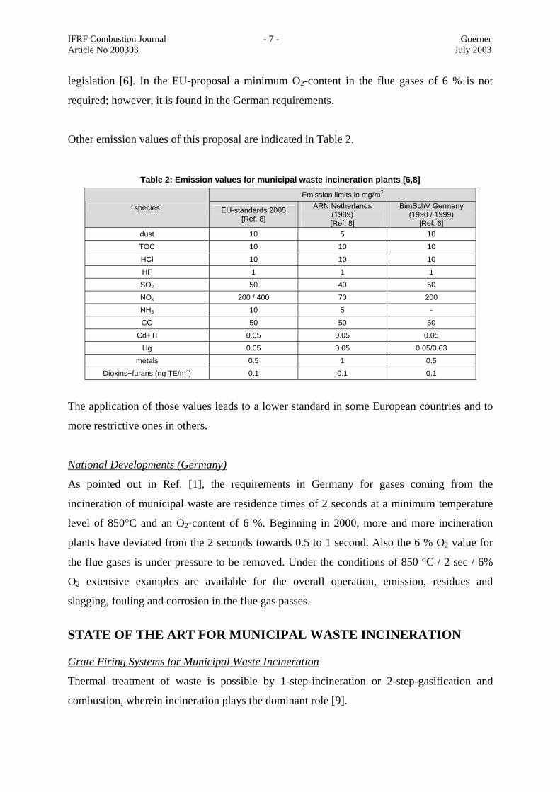
Other emission values of this proposal are indicated in Table 2.
Table 2: Emission values for municipal waste incineration plants [6,8]
Emission limits in mg/m3
species EU-standards 2005 [Ref. 8]
ARN Netherlands (1989) [Ref. 8]
BimSchV Germany (1990 / 1999)
[Ref. 6] dust 10 5 10
TOC 10 10 10
HCl 10 10 10
HF 1 1 1
SO2 50 40 50
NOx 200 / 400 70 200
NH3 10 5 -
CO 50 50 50
Cd+Tl 0.05 0.05 0.05
Hg 0.05 0.05 0.05/0.03
metals 0.5 1 0.5
Dioxins+furans (ng TE/m3) 0.1 0.1 0.1
The application of those values leads to a lower standard in some European countries and to
more restrictive ones in others.
National Developments (Germany)
As pointed out in Ref. [1], the requirements in Germany for gases coming from the
incineration of municipal waste are residence times of 2 seconds at a minimum temperature
level of 850°C and an O2-content of 6 %. Beginning in 2000, more and more incineration
plants have deviated from the 2 seconds towards 0.5 to 1 second. Also the 6 % O2 value for
the flue gases is under pressure to be removed. Under the conditions of 850 °C / 2 sec / 6%
O2 extensive examples are available for the overall operation, emission, residues and
slagging, fouling and corrosion in the flue gas passes.
STATE OF THE ART FOR MUNICIPAL WASTE INCINERATION Grate Firing Systems for Municipal Waste Incineration
Thermal treatment of waste is possible by 1-step-incineration or 2-step-gasification and
combustion, wherein incineration plays the dominant role [9].
IFRF Combustion Journal - 8 - Goerner Article No 200303 July 2003
Incinerators can be subdivided into grate firing systems, fluidised bed systems (stationary and
circulating FB´s) and fixed bed systems. In this area, grate firing systems are the common
system with a wide distribution and a long-term-experience.
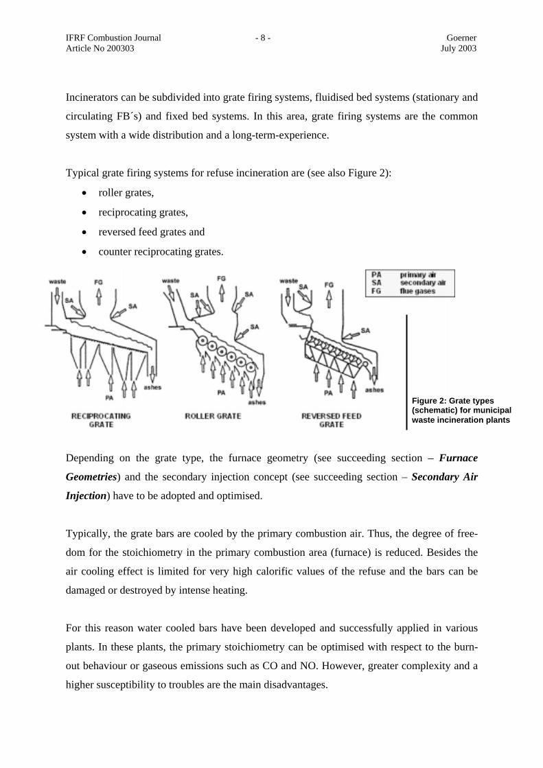
Typical grate firing systems for refuse incineration are (see also Figure 2):
• roller grates,
• reciprocating grates,
• reversed feed grates and
• counter reciprocating grates.
Depending on the grate type, the furnace geometry (see succeeding section – Furnace
Geometries) and the secondary injection concept (see succeeding section – Secondary Air
Injection) have to be adopted and optimised.
Typically, the grate bars are cooled by the primary combustion air. Thus, the degree of free-
dom for the stoichiometry in the primary combustion area (furnace) is reduced. Besides the
air cooling effect is limited for very high calorific values of the refuse and the bars can be
damaged or destroyed by intense heating.
For this reason water cooled bars have been developed and successfully applied in various
plants. In these plants, the primary stoichiometry can be optimised with respect to the burn-
out behaviour or gaseous emissions such as CO and NO. However, greater complexity and a
higher susceptibility to troubles are the main disadvantages.
Figure 2: Grate types (schematic) for municipal waste incineration plants
IFRF Combustion Journal - 9 - Goerner Article No 200303 July 2003
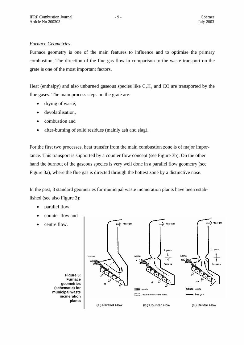
Figure 3:Furnace
geometries(schematic) for
municipal wasteincineration
plants(a.) Parallel Flow (b.) Counter Flow (c.) Centre Flow
Furnace Geometries
Furnace geometry is one of the main features to influence and to optimise the primary
combustion. The direction of the flue gas flow in comparison to the waste transport on the
grate is one of the most important factors.
Heat (enthalpy) and also unburned gaseous species like CxHy and CO are transported by the
flue gases. The main process steps on the grate are:
• drying of waste,
• devolatilisation,
• combustion and
• after-burning of solid residues (mainly ash and slag).
For the first two processes, heat transfer from the main combustion zone is of major impor-
tance. This transport is supported by a counter flow concept (see Figure 3b). On the other
hand the burnout of the gaseous species is very well done in a parallel flow geometry (see
Figure 3a), where the flue gas is directed through the hottest zone by a distinctive nose.
In the past, 3 standard geometries for municipal waste incineration plants have been estab-
lished (see also Figure 3):
• parallel flow,
• counter flow and
• centre flow.

IFRF Combustion Journal - 10 - Goerner Article No 200303 July 2003
The main advantages and disadvantages of the different systems are tabulated in Table 3.
Table 3: Advantages and disadvantages of the different furnace geometries
parallel flow counter flow centre flow
pyrolysis gases pass through the hottest area and therefore are burnt out satisfactorily. suitable for lower LCV
energy transfer from main combustion area to the drying and gasification area suitable for higher LCV
very flexible for different heat release distributions on the grate suitable for a wider range of LCV
advantages
energy transfer from main combustion area to ignition area is just by radiation
pyrolysis gases can bypass the hottest area and may cause burnout problems
flow and mixing pattern after the passage to the 1. pass sensible to disturbances
disadvantages
A lot of variants in geometries deviating from the base concepts as discussed above are on the
market. This fact does not so much depend on real process reasons but is due to manufacturer
specific developments or patent situation.
Secondary Air Injection
By splitting up the total combustion air (having an over-stoichiometry of 1.3 to 1.8) to
primary air and secondary air; the combustion conditions in the furnace can be controlled to
give near-stoichiometric conditions. The partitioning ratio of primary to secondary air is
between 80/20 (old plants) to 40/60 (tendency for new plants). The task of secondary air is to
complete the burnout of the hydrocarbons and carbon monoxide. In addition, secondary air
can be used as a mixing device for flue gases. Depending on the different furnace geometries,
the secondary air nozzle arrangement can also be optimised.
(a) Normal Configuration (b) Tangential Configuration (c) Static Mixing Device
Figure 4: Different Secondary Air Injection Concepts
IFRF Combustion Journal - 11 - Goerner Article No 200303 July 2003
A typical position for secondary air injection is to the transition area between the furnace and
the first pass of the boiler (radiative pass, see Figure 4a). The parameters are the number of
nozzles, the nozzle diameter, the nozzle spacing and the horizontal and/or vertical inclination.
New developments are tangential nozzle arrangements – similar to the firing concepts of
tangentially fired boilers [10], (Figure 4b) or static mixing devices in the flue gas pass [11],
[12] (Figure 4c, see also succeeding sections of this paper – Modification of Secondary Air
Injection and Optimisation of Secondary Air Injection).
Boiler Tube Lining
Normal boiler steel tubes are heavily endangered by thermo-chemical attacks especially in
the high temperature areas of the furnace. For this reason, refractory lining is applied. Typical
lining materials are ceramics like Al2O3, SiO2, SiC and others in different mixtures,
combinations and bonds.
Beside chemical protection, thermal isolation is also an important function. By varying the
coefficient of thermal conductivity or the thickness of the material layer heat extraction from
the furnace can be controlled.
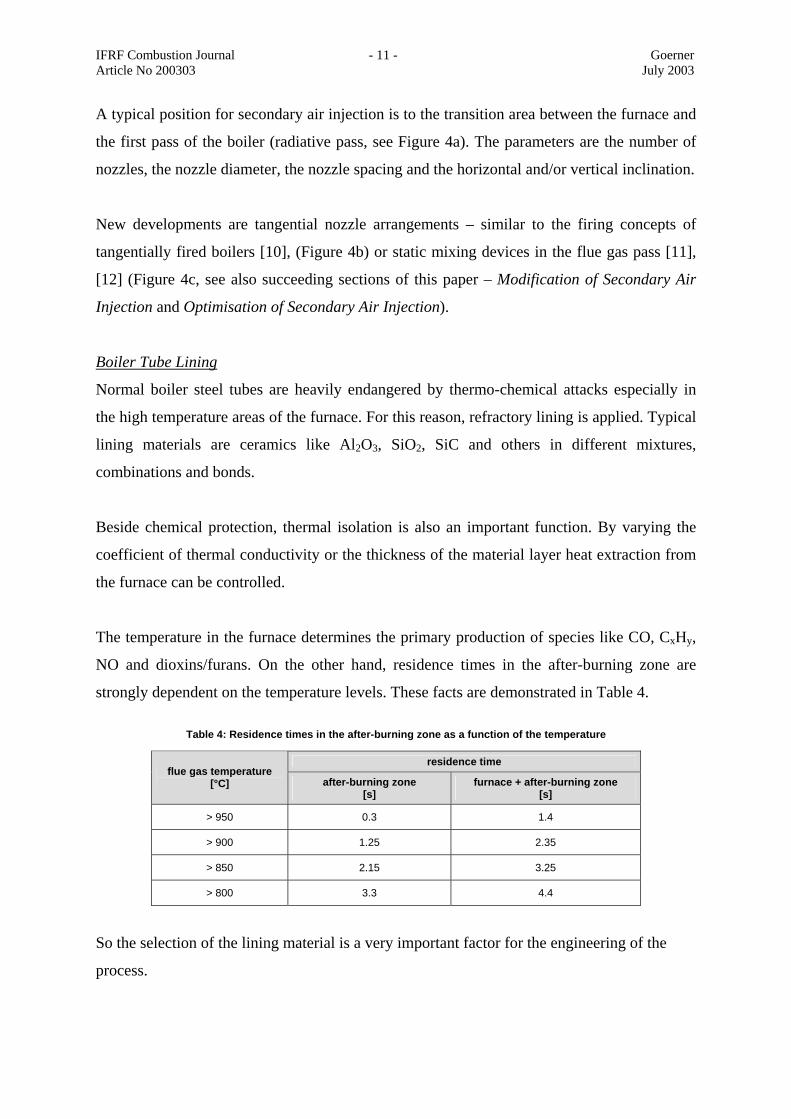
The temperature in the furnace determines the primary production of species like CO, CxHy,
NO and dioxins/furans. On the other hand, residence times in the after-burning zone are
strongly dependent on the temperature levels. These facts are demonstrated in Table 4.
Table 4: Residence times in the after-burning zone as a function of the temperature
residence time flue gas temperature
[°C] after-burning zone [s]
furnace + after-burning zone [s]
> 950 0.3 1.4
> 900 1.25 2.35
> 850 2.15 3.25
> 800 3.3 4.4
So the selection of the lining material is a very important factor for the engineering of the
process.
IFRF Combustion Journal - 12 - Goerner Article No 200303 July 2003
PROBLEMS ENCOUNTERED IN ACTUAL INCINERATION PLANTS Changing Waste Quality
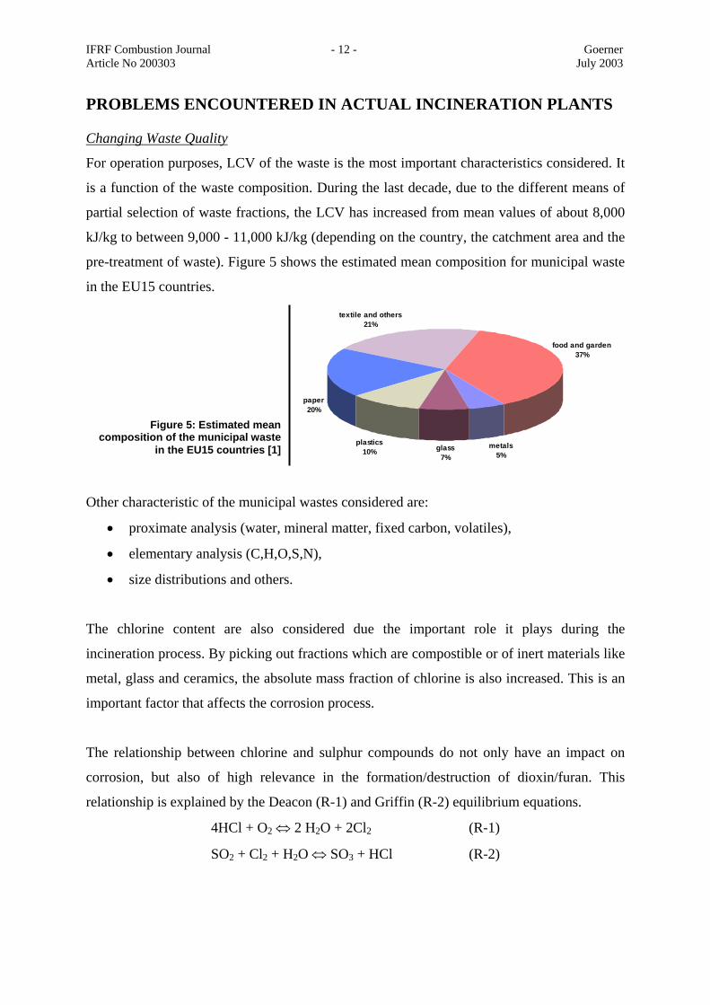
For operation purposes, LCV of the waste is the most important characteristics considered. It
is a function of the waste composition. During the last decade, due to the different means of
partial selection of waste fractions, the LCV has increased from mean values of about 8,000
kJ/kg to between 9,000 - 11,000 kJ/kg (depending on the country, the catchment area and the
pre-treatment of waste). Figure 5 shows the estimated mean composition for municipal waste
in the EU15 countries.
Other characteristic of the municipal wastes considered are:
• proximate analysis (water, mineral matter, fixed carbon, volatiles),
• elementary analysis (C,H,O,S,N),
• size distributions and others.
The chlorine content are also considered due the important role it plays during the
incineration process. By picking out fractions which are compostible or of inert materials like
metal, glass and ceramics, the absolute mass fraction of chlorine is also increased. This is an
important factor that affects the corrosion process.
The relationship between chlorine and sulphur compounds do not only have an impact on
corrosion, but also of high relevance in the formation/destruction of dioxin/furan. This
relationship is explained by the Deacon (R-1) and Griffin (R-2) equilibrium equations.
4HCl + O2 ⇔ 2 H2O + 2Cl2 (R-1)
SO2 + Cl2 + H2O ⇔ SO3 + HCl (R-2)
metals5%
glass7%
plastics10%
paper20%
textile and others21%
food and garden37%
Figure 5: Estimated meancomposition of the municipal waste
in the EU15 countries [1]
IFRF Combustion Journal - 13 - Goerner Article No 200303 July 2003
which determines the ratio HCl/Cl2. The Cl/S ratio in waste is different from that of chlorine
and sulphur content of coals, thus dioxins/furans play does not have a significant role in fossil
fuel combustion, but are of relevance for waste incineration.
Increasing Combustion Temperature
An increase in the LCV leads to an increase of the mean furnace temperature. Plants designed
for low LCV´s (parallel flow) have extremely high combustion temperatures, which cause
corrosion, slagging and fouling in the furnace and in the radiative, and convective passes of
the boiler (see succeeding section – Corrosion). Also sulphatisation (transition of chlorines to
sulphates) is decreased by temperatures higher than 800 to 850 °C. As a consequence, these
reactions take place in the dust layer in the boiler and cause corrosion by producing HCl or
Cl2 in the direct vicinity of the metallic boiler tubes.
At high temperatures, dust particles become liquid or partially liquid (sticky). The first effect
is used in slag tap furnaces for low volatile coals to form a molten layer with constant
thickness which protects the wall material. Sticky particles are the dominant problem. Heavy
slagging on the furnace walls leads to operational restrictions. The cleanup of the walls is
sometimes possible by soot blowers (steam or water). Very often a plant shut-down is
necessary to break-up and remove the compact solidified slag layer.
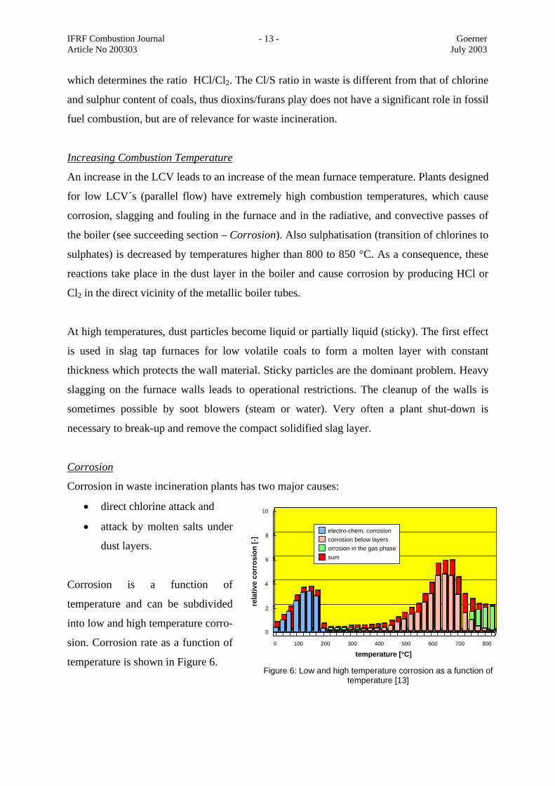
Corrosion
Corrosion in waste incineration plants has two major causes:
• direct chlorine attack and
• attack by molten salts under
dust layers.
Corrosion is a function of
temperature and can be subdivided
into low and high temperature corro-
sion. Corrosion rate as a function of
temperature is shown in Figure 6.
0 100 200 300 400 500 600 700 800
temperature [°C]
0
2
4
6
8
10
rela
tive
corr
osio
n [-]
electro-chem. corrosioncorrosion below layersorrosion in the gas phasesum
Figure 6: Low and high temperature corrosion as a function of temperature [13]
IFRF Combustion Journal - 14 - Goerner Article No 200303 July 2003
The first cause is the consequence of insufficient sulphatisation in the gas phase at high
temperatures. Subsequently the following reactions take place in the dust layer (examples,
also valid for K and Mg instead of Na) [14]:
2NaCl + SO3 + H2O ⇔ Na2SO4 + 2HCl (R-3)
2NaCl + SO2 + O2 ⇔ Na2SO4 + 2Cl (R-4)
HCl or chlorine in statu nascendi is present and leads to a direct attack.
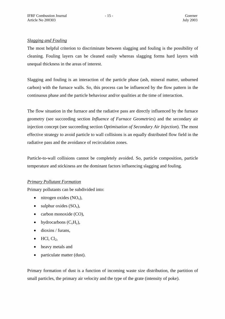
The composition of waste incineration dust is very complex because of the great variety of
species in the plant input flow. So dust forms a eutectic system with partially very low
melting temperatures of the salts. Table 5 demonstrates this fact.
Figure 5: Ash melting temperatures for different species [14]
Pure species melting temp. °C
Eutectic systems mol-%
melting temp. °C
NaCl 801 25 NaCl – 75 FeCl3 156
KCl 772 55 ZnCl2 – 45 KCl 230
MgCl2 714 60 KCl – 40 FeCl2 355
CaCl2 772 58 NaCl – 42 FeCl2 370
FeCl2 676 90 PbCl2 – 10 MgCl2 460
FeCl3 303
49 NaCl – 51 CaCl2 500
It can be seen that up to the convective pass of the boiler, the melting temperature of particles
or dust is possible and will also take place [15, 16].
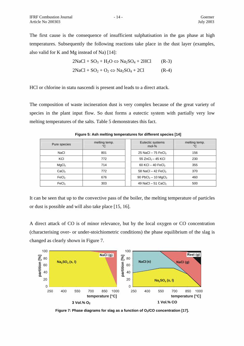
A direct attack of CO is of minor relevance, but by the local oxygen or CO concentration
(characterising over- or under-stoichiometric conditions) the phase equilibrium of the slag is
changed as clearly shown in Figure 7.
part
ition
[%]
temperature [°C]
Na SO (s, l)2 4
part
ition
[%]
temperature [°C]
Na SO (s, l)2 4
3 Vol.% O2 1 Vol.% CO
Figure 7: Phase diagrams for slag as a function of O2/CO concentration [17].
IFRF Combustion Journal - 15 - Goerner Article No 200303 July 2003
Slagging and Fouling
The most helpful criterion to discriminate between slagging and fouling is the possibility of
cleaning. Fouling layers can be cleaned easily whereas slagging forms hard layers with
unequal thickness in the areas of interest.
Slagging and fouling is an interaction of the particle phase (ash, mineral matter, unburned
carbon) with the furnace walls. So, this process can be influenced by the flow pattern in the
continuous phase and the particle behaviour and/or qualities at the time of interaction.
The flow situation in the furnace and the radiative pass are directly influenced by the furnace
geometry (see succeeding section Influence of Furnace Geometries) and the secondary air
injection concept (see succeeding section Optimisation of Secondary Air Injection). The most
effective strategy to avoid particle to wall collisions is an equally distributed flow field in the
radiative pass and the avoidance of recirculation zones.
Particle-to-wall collisions cannot be completely avoided. So, particle composition, particle
temperature and stickiness are the dominant factors influencing slagging and fouling.
Primary Pollutant Formation
Primary pollutants can be subdivided into:
• nitrogen oxides (NOx),
• sulphur oxides (SOx),
• carbon monoxide (CO),
• hydrocarbons (CxHy),
• dioxins / furans,
• HCl, Cl2,
• heavy metals and
• particulate matter (dust).
Primary formation of dust is a function of incoming waste size distribution, the partition of
small particles, the primary air velocity and the type of the grate (intensity of poke).
IFRF Combustion Journal - 16 - Goerner Article No 200303 July 2003
Sulphur oxide, chlorine and heavy metal concentrations in the raw flue gas are a function of
the input stream and cannot be influenced by primary measures (dry additive sorption is not
really a primary measure).
Nitrogen oxides, carbon monoxide and dioxins / furans can be influenced to some extent by
oxygen concentration, residence time, temperature and mixing / turbulence (3T-rule: time-
temperature-turbulence). Increasing values of all 4 qualities reduce the CO concentration, but
increase the NOx. For minimising dioxins / furans oxygen concentration should be low and
temperature and residence time high.
Typical values for primary emissions (exit of furnace) are:
• NOx 200 to 400 mg/m3N
• dioxins / furans 0.2 to 0.6 ng TE/m3N.
NOx formation can be primarily influenced by air staging (primary to secondary air) or by
selective non-catalytic reduction (SNCR) injecting ammonia or urea.
by “DE NOVO” synthesis the values for dioxins / furans are increased respectively
depending on the flue gas cleaning concept. The main influencing factors are oxygen
concentration, dust (particle) concentration, concentration of catalysts (compounds of metals
or heavy metals), temperature and residence time. In the flue gas pass, the main place of
dioxin / furan synthesis (DE NOVO) is in the bag filter or in the electrostatic precipitator.
Cleaning devices for NOx and dioxins / furans must be implemented to reach the allowed
emission values. Catalysts are used for NOx (reduction) and for dioxins / furans (oxidation).
Adsorption with coal char (brown and hard coal) is also very common, but needs waste
management for this medium.
MATHEMATICAL MODELLING AND SIMULATIONS Gas Phase Modelling
Mathematical modelling and numerical simulation of fossil fired systems have reached a high
level and are used in a wide range of applications in research and development [18]. This is
IFRF Combustion Journal - 17 - Goerner Article No 200303 July 2003
valid for gas, oil and coal dust firing, but not for fixed beds or fluidised beds because of the
problems in describing the solid phase (dispersed phase) and its interaction with the gas phase
(continuous phase). Therefore for municipal waste incineration plants the description of the
furnace and the radiative and convective parts of the boiler is possible. The boundary
conditions at the fixed bed surface are problematic because of the variability of the waste
properties and the chemical and thermal interaction between the primary combustion air and
the waste. Model developments specially take place in this area and are described to some
extent in the succeeding section (Modelling of the Waste Combustion Process) [19, 20, 21].
Modellin of the Waste Combustion Process
Fixed bed modelling has been carried out by different groups [19, 23, 24, 25]. The main
difference in the models is the level of approximation:
• zero-dimension model (integral assumption for the heat release and the released
species)
• one-dimensional modelling (heat release and species concentrations profiles over the
grate length),
• two-dimensional modelling (also estimated profiles in crosswise direction),
• two-dimensional modelling (also burnout progress in the vertical direction, that is in
the fixed bed depth) and
• fully three-dimensional modelling.
Crosswise direction profiles are a consequence of unequally distributed waste mass flow or
waste qualities. In general this information is an empirical input and does not lead to a model
of universal validity.
Vertical burnout progress is described by Swithenbank [24], but needs data on waste trans-
port, waste qualities and additional assumptions on the combustion behaviour in the fixed
bed.
Assuming one-dimensional heat release, species concentration profiles can take into account
empirically the grate system in combination with furnace geometry, position of fire (main
combustion zone), waste quality (LCV, water content, volatile content and others). Results
shown in the succeeding section (Actual Projects and Results) are based on this approach.
IFRF Combustion Journal - 18 - Goerner Article No 200303 July 2003
A fully three-dimensional modelling is strongly dependent on a large number of waste
qualities and empirical information.
Particle Behaviour
Local particle concentration can be modelled in the Eulerian (continuous phase) and
Lagrangian (discrete phase) framework.
Euler-Euler-description reduces the numerical effort, but is reduced in significance and
accuracy related to thermo-chemical behaviour.
Euler-Lagrange-description can generally take into account:
• turbulent interaction between particulate and gaseous phase by Monte-Carlo-
modelling [18],
• equilibrium assumptions for the particle and gas phase by thermo-chemical modelling
[17],
• kinetically dominated reactions in the gas and the particle phase,
• particle size distribution depending qualities like emission coefficients, pore size
distributions and/or turbulent interaction to the gas phase,
A very high numerical effort is the major disadvantage of this method. Typical results are
shown in the succeeding section (Actual Projects and Results).
ACTUAL DEVELOPMENTS Modifications of the Grate
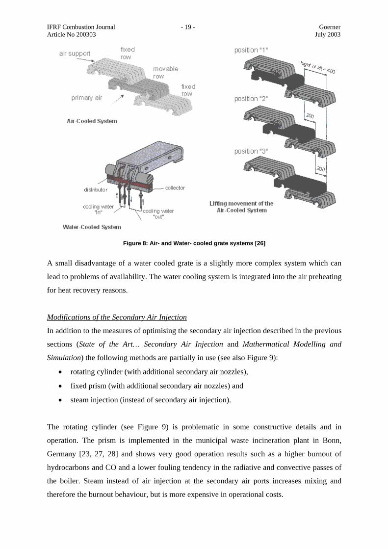
The main disadvantage of an air cooled combustion grate is that the primary air has the role
of both the combustion air and the cooling air. So, both functions cannot be decoupled. By
applying water cooled grates, the combustion air can be reduced which is advantageous to the
primary NO production. The thermal load of the grate can be heavily increased. Furthermore,
the furnace temperature is reduced by extracting heat from this area. A typical air- and water-
cooled grate and the cooling circuit can be seen in Figure 8.
IFRF Combustion Journal - 19 - Goerner Article No 200303 July 2003
A small disadvantage of a water cooled grate is a slightly more complex system which can
lead to problems of availability. The water cooling system is integrated into the air preheating
for heat recovery reasons.
Modifications of the Secondary Air Injection
In addition to the measures of optimising the secondary air injection described in the previous
sections (State of the Art… Secondary Air Injection and Mathermatical Modelling and
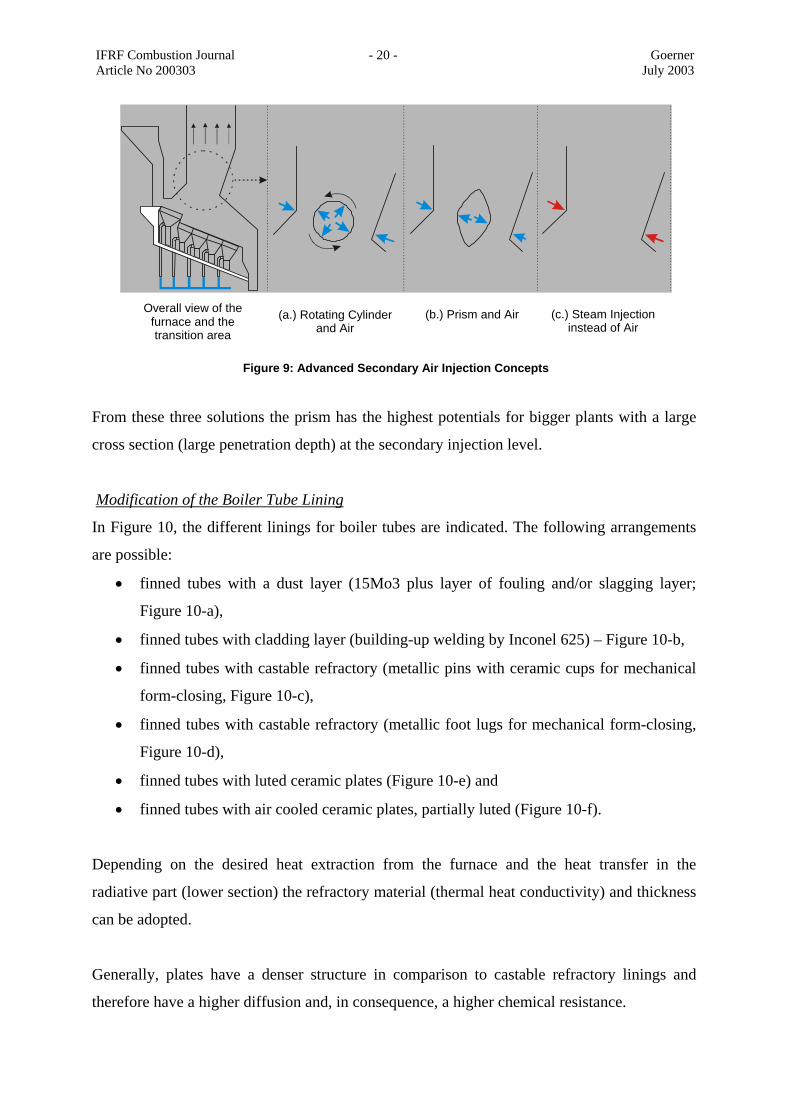
Simulation) the following methods are partially in use (see also Figure 9):
• rotating cylinder (with additional secondary air nozzles),
• fixed prism (with additional secondary air nozzles) and
• steam injection (instead of secondary air injection).
The rotating cylinder (see Figure 9) is problematic in some constructive details and in
operation. The prism is implemented in the municipal waste incineration plant in Bonn,
Germany [23, 27, 28] and shows very good operation results such as a higher burnout of
hydrocarbons and CO and a lower fouling tendency in the radiative and convective passes of
the boiler. Steam instead of air injection at the secondary air ports increases mixing and
therefore the burnout behaviour, but is more expensive in operational costs.
Figure 8: Air- and Water- cooled grate systems [26]
IFRF Combustion Journal - 20 - Goerner Article No 200303 July 2003
From these three solutions the prism has the highest potentials for bigger plants with a large
cross section (large penetration depth) at the secondary injection level.
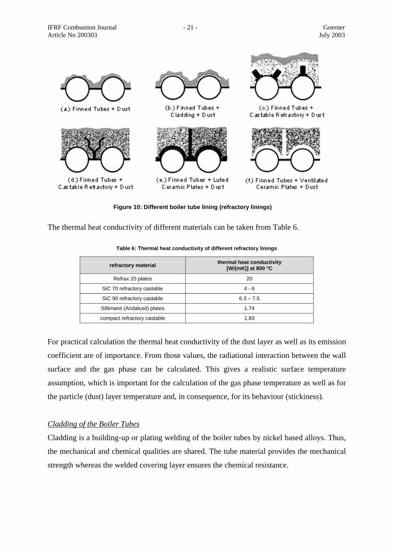
Modification of the Boiler Tube Lining
In Figure 10, the different linings for boiler tubes are indicated. The following arrangements
are possible:
• finned tubes with a dust layer (15Mo3 plus layer of fouling and/or slagging layer;
Figure 10-a),
• finned tubes with cladding layer (building-up welding by Inconel 625) – Figure 10-b,
• finned tubes with castable refractory (metallic pins with ceramic cups for mechanical
form-closing, Figure 10-c),
• finned tubes with castable refractory (metallic foot lugs for mechanical form-closing,
Figure 10-d),
• finned tubes with luted ceramic plates (Figure 10-e) and
• finned tubes with air cooled ceramic plates, partially luted (Figure 10-f).
Depending on the desired heat extraction from the furnace and the heat transfer in the
radiative part (lower section) the refractory material (thermal heat conductivity) and thickness
can be adopted.
Generally, plates have a denser structure in comparison to castable refractory linings and
therefore have a higher diffusion and, in consequence, a higher chemical resistance.
Overall view of the furnace and the transition area
(a.) Rotating Cylinderand Air
(b.) Prism and Air (c.) Steam Injection instead of Air
Figure 9: Advanced Secondary Air Injection Concepts
IFRF Combustion Journal - 21 - Goerner Article No 200303 July 2003
The thermal heat conductivity of different materials can be taken from Table 6.
Table 6: Thermal heat conductivity of different refractory linings
refractory material thermal heat conductivity [W/(mK)] at 800 °C
Refrax 20 plates 20
SiC 70 refractory castable 4 - 6
SiC 90 refractory castable 6.3 – 7.5
Sillimanit (Andalusit) plates 1.74
compact refractory castable 1.83
For practical calculation the thermal heat conductivity of the dust layer as well as its emission
coefficient are of importance. From those values, the radiational interaction between the wall
surface and the gas phase can be calculated. This gives a realistic surface temperature
assumption, which is important for the calculation of the gas phase temperature as well as for
the particle (dust) layer temperature and, in consequence, for its behaviour (stickiness).
Cladding of the Boiler Tubes
Cladding is a building-up or plating welding of the boiler tubes by nickel based alloys. Thus,
the mechanical and chemical qualities are shared. The tube material provides the mechanical
strength whereas the welded covering layer ensures the chemical resistance.
Figure 10: Different boiler tube lining (refractory linings)

IFRF Combustion Journal - 22 - Goerner Article No 200303 July 2003
To protect the metallic pipe material (typically 15Mo3) cladding is applied below the ceramic
refractory lining and in the area behind the refractory lining (metallic pipe without lining) in
the flue gas pass.
Typical welding materials can be specified as indicated in Table 7.
Table 7: Welding materials for cladding purposes [32]
composition welding material
element partition [%]
NiCr625 2.4831 Inconel 625 C < 0.03
Cr 22
Mo 9
Fe < 3
Nb 3,5
Ni rest
The most important value for resistance to corrosion is the Fe content. In the welded layer it
should be lower than 5% in any case, but the lower the better.
Fe concentration is also dependent on the welding parameters such as welding type (MIG or
MAG), welding velocity, absolute welding-current and frequency (temperature of the fused
mass), direction of welding (vertical or horizontal, upward or downward) and others. A
typical plating coat thickness is 2 mm.
In practical experiences very good results have been achieved with this method. The costs are
relatively high (2,500 Euro/m3), but give a longer operation period.
ADVANCED CONTROL BY NUERAL NETS AND FUZZY LOGIC Fuzzy Logic Concept (FL)
Mass flow, calorific value and all mechanical qualities of municipal waste fluctuate over a
wide range. For example the mean lower calorific value can be calculated by an overall
balance over the plant, defining waste as thermal input and the live steam as output. In
systems engineering such boundary conditions are described as fuzzy. The fuzzy logic theory
of Zadeh [33] can be applied to such systems very successfully. The general procedure in
IFRF Combustion Journal - 23 - Goerner Article No 200303 July 2003
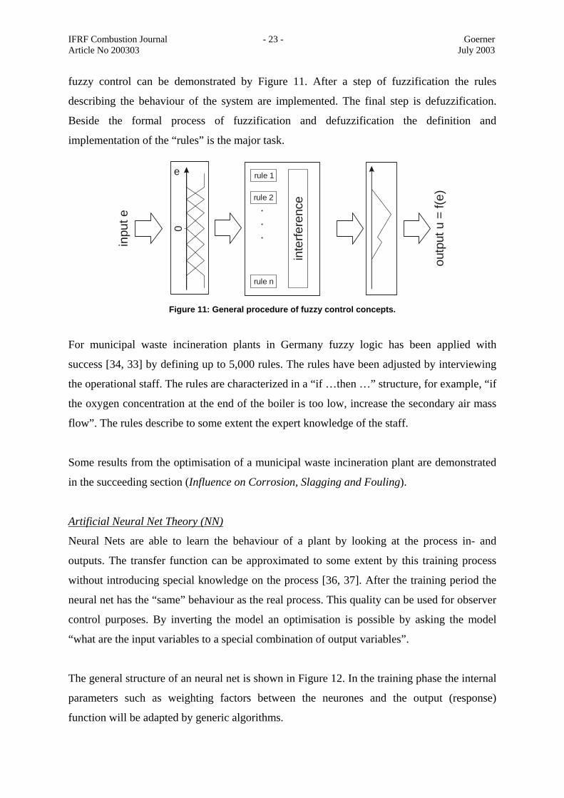
fuzzy control can be demonstrated by Figure 11. After a step of fuzzification the rules
describing the behaviour of the system are implemented. The final step is defuzzification.
Beside the formal process of fuzzification and defuzzification the definition and
implementation of the “rules” is the major task.
For municipal waste incineration plants in Germany fuzzy logic has been applied with
success [34, 33] by defining up to 5,000 rules. The rules have been adjusted by interviewing
the operational staff. The rules are characterized in a “if …then …” structure, for example, “if
the oxygen concentration at the end of the boiler is too low, increase the secondary air mass
flow”. The rules describe to some extent the expert knowledge of the staff.
Some results from the optimisation of a municipal waste incineration plant are demonstrated
in the succeeding section (Influence on Corrosion, Slagging and Fouling).
Artificial Neural Net Theory (NN)
Neural Nets are able to learn the behaviour of a plant by looking at the process in- and
outputs. The transfer function can be approximated to some extent by this training process
without introducing special knowledge on the process [36, 37]. After the training period the
neural net has the “same” behaviour as the real process. This quality can be used for observer
control purposes. By inverting the model an optimisation is possible by asking the model
“what are the input variables to a special combination of output variables”.
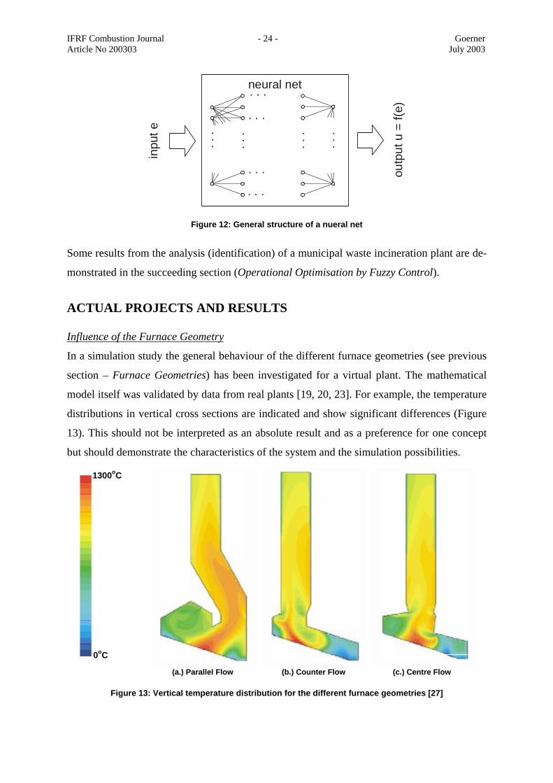
The general structure of an neural net is shown in Figure 12. In the training phase the internal
parameters such as weighting factors between the neurones and the output (response)
function will be adapted by generic algorithms.
inpu
t e
0e rule 1
rule 2
rule n
inte
rfere
nce
.
.
.
outp
ut u
= f(
e)
Figure 11: General procedure of fuzzy control concepts.
IFRF Combustion Journal - 24 - Goerner Article No 200303 July 2003
Some results from the analysis (identification) of a municipal waste incineration plant are de-
monstrated in the succeeding section (Operational Optimisation by Fuzzy Control).
ACTUAL PROJECTS AND RESULTS Influence of the Furnace Geometry
In a simulation study the general behaviour of the different furnace geometries (see previous
section – Furnace Geometries) has been investigated for a virtual plant. The mathematical
model itself was validated by data from real plants [19, 20, 23]. For example, the temperature
distributions in vertical cross sections are indicated and show significant differences (Figure
13). This should not be interpreted as an absolute result and as a preference for one concept
but should demonstrate the characteristics of the system and the simulation possibilities.
inpu
t e
outp
ut u
= f(
e)
neural net
......
......
. . .
. . .
. . .
. . .
Figure 12: General structure of a nueral net
1300oC
0oC
(a.) Parallel Flow (b.) Counter Flow (c.) Centre Flow
Figure 13: Vertical temperature distribution for the different furnace geometries [27]
IFRF Combustion Journal - 25 - Goerner Article No 200303 July 2003
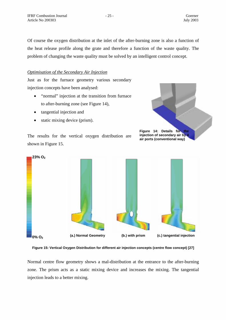
Of course the oxygen distribution at the inlet of the after-burning zone is also a function of
the heat release profile along the grate and therefore a function of the waste quality. The
problem of changing the waste quality must be solved by an intelligent control concept.
Optimisation of the Secondary Air Injection
Just as for the furnace geometry various secondary
injection concepts have been analysed:
• “normal” injection at the transition from furnace
to after-burning zone (see Figure 14),
• tangential injection and
• static mixing device (prism).
The results for the vertical oxygen distribution are
shown in Figure 15.
Normal centre flow geometry shows a mal-distribution at the entrance to the after-burning
zone. The prism acts as a static mixing device and increases the mixing. The tangential
injection leads to a better mixing.
Figure 14: Details for theinjection of secondary air by 4air ports (conventional way)
23% O2
0% O2 (a.) Normal Geometry (b.) with prism (c.) tangential injection
Figure 15: Vertical Oxygen Distribution for different air injection concepts (centre flow concept) [27]

IFRF Combustion Journal - 26 - Goerner Article No 200303 July 2003
Influence of the Refractory Lining
Refractory lining and dust layers on the finned tubes can dramatically influence the
temperature distribution in the flue gases. This is a direct consequence of the furnace heat
extraction and the modified reaction rates. Figure 16 gives an impression of these dramatic
changes.
Standard castable SiC material is used as the reference case. Compared to the luted plates
their insulation effectiveness is relatively high.
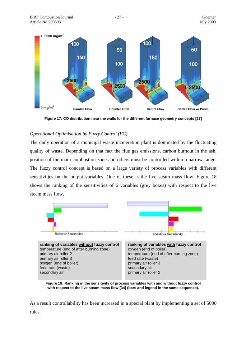
Influences on Corrosion, Slagging and Fouling
The local CO concentrations near the furnace walls (flue gas side) can be used for some
preliminary statements on the direct corrosion and the equilibrium between sulphates and
chlorines in the dust layer. Therefore these distributions have been calculated and plotted in
Figure 17. As expected, the highest CO concentrations can be seen in the main combustion
area.
The reduction of CO by its reaction with secondary air is a function of the injection concept.
In general, a very fast reduction can be achieved by the counter flow and the centre flow
concept.
1300oC
0oC (a.) Castable SiC (b.) luted SiC-plates (c.) air cooled SiC plates
+ dust
Figure 16: Vertical temperature distributions for different refractory linings (conventional way) [27]
IFRF Combustion Journal - 27 - Goerner Article No 200303 July 2003
Operational Optimisation by Fuzzy Control (FC)
The daily operation of a municipal waste incineration plant is dominated by the fluctuating
quality of waste. Depending on that fact the flue gas emissions, carbon burnout in the ash,
position of the main combustion zone and others must be controlled within a narrow range.
The fuzzy control concept is based on a large variety of process variables with different
sensitivities on the output variables. One of these is the live steam mass flow. Figure 18
shows the ranking of the sensitivities of 6 variables (grey boxes) with respect to the live
steam mass flow.
As a result controllability has been increased in a special plant by implementing a set of 5000
rules.
0 mg/m3 Parallel Flow Counter Flow Centre Flow Centre Flow w/ Prism
> 5000 mg/m3
Figure 17: CO distribution near the walls for the different furnace geometry concepts [27]
ranking of variables with fuzzy control oxygen (end of boiler) temperature (end of after burning zone) feed rate (waste) primary air roller 3 secondary air primary air roller 2
ranking of variables without fuzzy controltemperature (end of after burning zone) primary air roller 2 primary air roller 3 oxygen (end of boiler) feed rate (waste) secondary air
Figure 18: Ranking in the sensitivity of process variables with and without fuzzy control with respect to the live steam mass flow [34] (bars and legend in the same sequence).
IFRF Combustion Journal - 28 - Goerner Article No 200303 July 2003
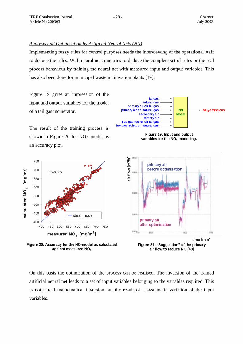
Analysis and Optimisation by Artificial Neural Nets (NN)
Implementing fuzzy rules for control purposes needs the interviewing of the operational staff
to deduce the rules. With neural nets one tries to deduce the complete set of rules or the real
process behaviour by training the neural net with measured input and output variables. This
has also been done for municipal waste incineration plants [39].
Figure 19 gives an impression of the
input and output variables for the model
of a tail gas incinerator.
The result of the training process is
shown in Figure 20 for NOx model as
an accuracy plot.
On this basis the optimisation of the process can be realised. The inversion of the trained
artificial neural net leads to a set of input variables belonging to the variables required. This
is not a real mathematical inversion but the result of a systematic variation of the input
variables.
tailgasnatural gas
primary air on tailgasprimary air on natural gas NN NOX-emissions
secondary air Modeltertiary air
flue gas recirc. on tailgasflue gas recirc. on natural gas
Figure 19: Input and output variables for the NOx modelling.
400
450
500
550
600
650
700
750
400 450 500 550 600 650 700 750
measured NOX [mg/m3]
calc
ulat
ed N
OX
[mg/
m3 ]
ideal model
R2=0,865
Figure 20: Accuracy for the NO-model as calculated against measured NOx
Figure 21: “Suggestion” of the primary air flow to reduce NO [40]
3 /h]
air f
low
[m3 /h
]
time [min]
primary airbefore optimisation
primary airafter optimisation
IFRF Combustion Journal - 29 - Goerner Article No 200303 July 2003
For a tail gas after-burning unit, the emission of NO was reduced by applying neural nets
[40]. As an example a “suggestion” of the model is shown in Figure 21, where the primary air
should be reduced and the tertiary air be increased (reduction of the primary stoichiometry).
By applying neural nets for this plant the NOx emissions could be reduced by 5 % without
changing any hardware of the plant.
CONCLUSIONS Municipal waste incineration is an important factor in the EC economy. Environmental as
well as economic constraints govern the plant operation. Harmonisation in the EC and
liberalisation of the common market especially with respect to electrical generation (as low as
2 Euro Cents/kWh) put pressure on the costs.
On the basis of a conventional municipal waste incineration plant with a grate firing system
some new technical developments and new materials or material applications have been
demonstrated.
Mathematical modelling and simulations (CFD) form a helpful tool to optimise plant
operation. Not all relevant phenomena are understood and described in full detail, but CFD-
calculations give an impression of reciprocal relationships.
New tools like fuzzy logic (FL) or artificial neural nets (NN) are front-line technologies
leading to a useful application in practice.
SYMBOLS / ABBREVIATIONS
CFD computational fluid dynamics
EC European Community
EU15 European Union member countries
FB fluidised bed
FC fuzzy control
FG flue gas
FL fuzzy logic
LCV lower calorific value

IFRF Combustion Journal - 30 - Goerner Article No 200303 July 2003
MAG metal-argon-welding
MIG metal-inert-gas-welding
NN (artificial) neural nets
PA primary air
SA secondary air
TOC total oxidisable carbon
REFERENCES [1] N.N.: Study on Energy Management and Optimisation in Industry. Document prepared
for the EU by AEA Technology, July 2000 [2] N.N.: 3.Allgemeine Verwaltungsvorschrift zum Abfallgesetz (TA Siedlungsabfall
(TASi), Bundesgesetzblatt,Germany, 1992 [3] N.N.: Council Directive 96/61/EU concerning Integrated Pollution Prevention and
Control, 24.9.1996, Official J. L 257, 10/10/1996, pp 0026-0040 [4] N.N.: Handbook on the Implementation of EC Environmental Legislation. [5] N.N.: Proposal for a Council Directive on the Incineration of Waste, COM(1998)558
final, 1998 [6] N.N.: 17. BImSchV (Bundesimmissionsschutzverordnung (1990/1999) [7] N.N.: Amended Proposal for a European Parliament and Council Directive on the
incineration of waste. COM(1999)330 final, 1999 [8] Blokland, J.; Boonzaaijer, W.: Legislative Procedure in the European Parliament and
Common Position of the Council. Abfallmanagement 2000, VDI-Bildungswerk, 17./18..02.2000, Ratingen, Germany
[9] Görner, K.; Hübner, K.: Hütte – Umwelttechnik. Springer-Verlag, Berlin, Heidelberg,
1999 [10] Vogler, E.: Erfahrungen mit drallstabilisierter Nachverbrennung als Primärmaßnahme
bei der Restabfallverbrennung. VGB Kraftwerkstechnik, 9(2000), pp 62-64 [11] Görner, K. ; Klasen, Th. : Sekundärluftprisma zur Optimierung der Sekundärluft-
eindüsung. VDI-Bildungswerk, München, 14./15.9.2000 [12] Görner, K., Klasen, T., Kümmel, J.: Numerische Berechung und Optimierung der
MVA Bonn, VDI-Berichte 1492, 19. Deutscher Flammentag, Dresden, pp 331-336
IFRF Combustion Journal - 31 - Goerner Article No 200303 July 2003
[13] Seier, J.; Albert, F.: Optimierung der energetischen Nutzung von Abfällen in Müllheizkraftwerken durch die Anwendung von Fremdüberhitzung. VDI-Bericht Nr.1390, 1998
[14] Husemann, R.U.: Korrosionserscheinungen und deren Reduzierung an Verdampfern
und überhitzern in kommunalen Müllverbrennungsanlagen. VGB-Kraftwerkstechnik, 72(1992)H.10, pp 918-927
[15] Reichel, H.-H., Schirmer, U.: Waste incinerator plants in the FRG : Construction,
materials, investigation on cases of corrosion, Werkstoffe und Korrosion, 40(1989), pp 135-141
[16] Schumacher, F.: Korrosionen in Abfallverbrennungsanlagen, BWK, 48(1998),
no.11/12, pp 74-80 [17] Born, M.: TU Freiberg, Germany, private communication [18] Görner, K.: Technische Verbrennungssysteme – Grundlagen und Anwendungen,
Springer Verlag, Heidelberg, 1991 [19] Klasen, T., Görner, K.: Numerical calculation and optimization of a large municipal
waste incinerator plant, 2nd Int. Symposium on incineration and flue gas treatment technologies, Sheffield University, U.K., 1999
[20] Klasen, Th., Görner, K.: Simulation und Optimierung einer Müllverbrennungsanlage,
VDI-GET Fachtagung „Modellierung und Simulation von Dampferzeugern und Feuerungen“, Braunschweig, 1998
[21] Nasserzadeh, V., Swithenbank, J., Scott, D., Jones, B.: Design Optimization of a large
MSW Incinerator, Waste Management, Sheffield, 1991, 11, pp 249 – 261 [22] Choi, S., Ryu, C.K., Shin, D.: A Computational Fluid Dynamics Evaluation of Good
Comb. Performance in Waste Incinerators, J. of the Air and Waste Management Ass., Korea, , 48(1998), pp 345 – 351
[23] Görner, K., Klasen, T., Kümmel, J.: Numerische Berechung und Optimierung der
MVA Bonn, VDI-Berichte 1492, 19th German Flame Days, Dresden, pp 331-336 [24] Zakaria, R.; Goh, Y.; Yang, Y.; Lim, C.; Goodfellow, J.; Chan, K.; Reynolds, G.;
Ward, D.; Siddall, R.; Nasserzadeh, V.; Swithenbank, J.: Fundamentals Aspects of Emissions from the Burning Bed in a Municipal Solid Waste Incinerator. 5th Europ. Conf. Ind. furnaces and Boilers INFUB, Porto, Portugal, 11./14./4.2000
[25] Beckmann, M.; Scholz, R.: Residence Time Behaviour of Solid Material in Grate
Systems. 5th Europ. Conf. Ind. furnaces and Boilers INFUB, Porto, Portugal, 11./14./4.2000
[26] N.N.: Rostbeläge für die thermische Abfallbehandlung. Fa. Koch, Schweiz, company
prospectus
IFRF Combustion Journal - 32 - Goerner Article No 200303 July 2003
[27] Klasen, Th. ,Görner, K. : Einfluss von Feuerraumgeometrie und –wandmaterial auf den Verbrennungsprozess sowie Vorhersage von gefährdeten Gebieten innerhalb einer MVA mit Hilfe von Simulationsrechnungen. VGB-Konferenz: Therm. Abfallverwertung 2000, Essen, Germany, 20./21.11.2000
[28] Patent of IBB Engineering Ltd. (Neuss), Nummer: DE 44 01 821 A1, Int. Cl.:F 23 G
5/14 [29] Görner, K. ; Klasen, Th. : Sekundärluftprisma zur Optimierung der Sekundärluft-
eindüsung. VDI-Bildungswerk, München, 14./15.9.2000 [30] Spiegel, M. ; Enders, M. : Mineralogical and microchemical study of high-temperature
reactions in fly ash scale from a waste incineration plant. Europ. J. Mineralogy, 11(1999), pp 763-774
[31] Spiegel, M.: Reactions between gas phase, deposits and metallic materials in chlorine-
containing atmospheres. Materials at high temperatures, 14(1998), pp 221-226 [32] N.N.: Uhlig Inc., Langelsheim, Germany, company prospectus [33] Zadeh, L.: Fuzzy Sets. Information and Control, 8 (1965) pp 338-353 [34] Gierend, Chr.; Born, M.: Fuzzy Control in waste incineration plants – experiences in
several typs of plants. ACHEMA Fair, Frankfurt/M, Germany, 22./27.6.2000 [35] Gierend, Chr.; Born, M.: Prozesssteuerung durch multivariable Kennfeldregelung am
Beispiel der Thermischen Abfallbehandlung mit Hilfe von Fuzzy-Regelungen. VGB-Konferenz: Therm. Abfallverwertung 2000, Essen, Germany, 20./21.11. 2000
[36] Kinnebrock, W.: Neuronale Netze. Oldenburg Verlag, München Wien, 1992 [37] Mühlhaus, R,; Görner, K.: Feuerungsanalyse und –optimierung mit Neuronalen Netzen.
19th German Flame Days, Dresden, Germany, Proceedings, 14./15.9.1999 [38] Mühlhaus, R.; Görner, K., Pollack, M.; Moll, W.; Pflipsen, K.: Neuronale Netze für die
Prozeßoptimierung. VDI-Tagung: Entwicklungslinien in der Energie- und Kraftwerkstechnik, Essen, Germany, 22./23.9.1999
[39] Mühlhaus, R.: Internal report, Lehrstuhl für Umweltverfahrenstechnik und Anlagen-
technik LUAT, 2000 [40] Mühlhaus, R.: Internal report, Lehrstuhl für Umweltverfahrenstechnik und Anlagen-
technik LUAT, 2000