warning: power amplifier contain high voltages of several hundred
TRANSCRIPT
Dr-Jordan-Design professional digital signal processing
page 1
Tutorial: Power Measurements of a high Power Amplifier Warning: Power amplifier contain high voltages of several hundred volts. Setup errors can easily damage your health or your equipment.
Purpose This tutorial shows how to measure the output power of an amplifier. We put special focus on distortion analysis.
Requirements • WinAudioMLS plus sweep/tracking plug-in • Signalgenerator PRO • Attenuator 10:1 • High power load resistor (4Ohm) • Handheld Volt meter • Soundcard (Setup uses a M-Audio Firewire 1814)
Device under test For this tutorial we use a cheap amplifier (Futuretec X-1250). This amplifier is specified as: Output power RMS 2x625W @4Ohm THD 0.05%
Setup • Set all gains to zero • Connect the output of your soundcard to input of the amplifier. • Connect the load resistor to the loudspeaker output. • Connect the input of the soundcard to the resistor to measure the output voltage. Do
not connect the soundcard directly. With power signal of around 1000W, the output voltage over the 4 Ohm resistor is up to 63V RMS and 89V peak. This voltage can easily destroy your soundcard. We recommend a attenuator used for oscilloscopes with a factor 1:10 or better 1:100.
Dr-Jordan-Design professional digital signal processing
page 2
Procedure
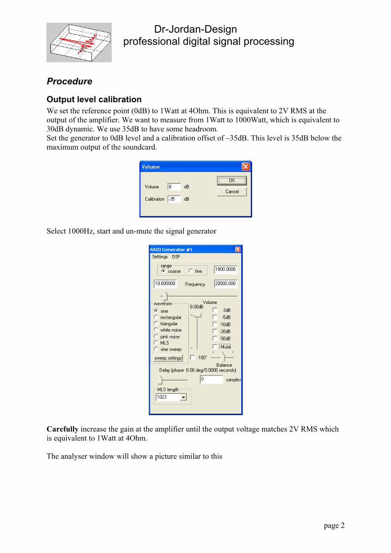
Output level calibration We set the reference point (0dB) to 1Watt at 4Ohm. This is equivalent to 2V RMS at the output of the amplifier. We want to measure from 1Watt to 1000Watt, which is equivalent to 30dB dynamic. We use 35dB to have some headroom. Set the generator to 0dB level and a calibration offset of –35dB. This level is 35dB below the maximum output of the soundcard.
Select 1000Hz, start and un-mute the signal generator
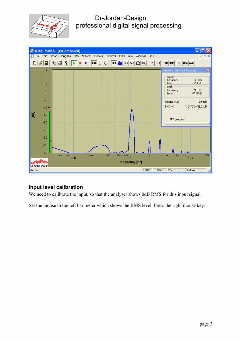
Carefully increase the gain at the amplifier until the output voltage matches 2V RMS which is equivalent to 1Watt at 4Ohm. The analyser window will show a picture similar to this
Dr-Jordan-Design professional digital signal processing
page 3
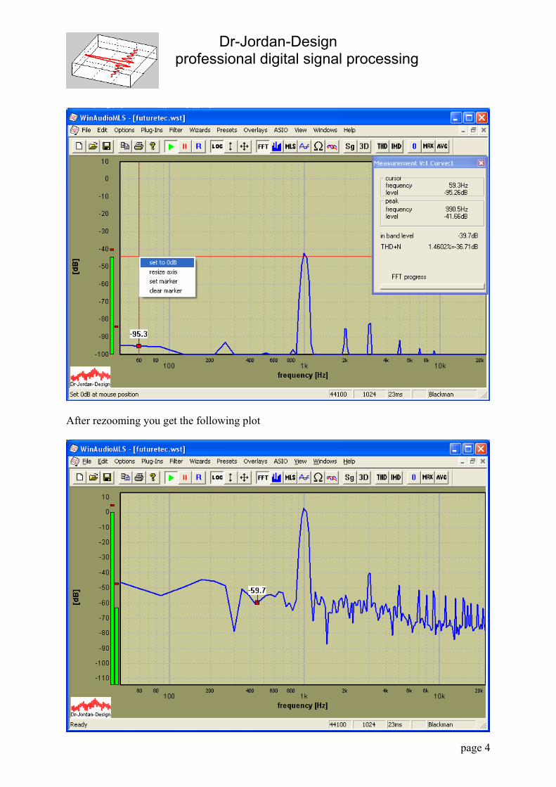
Input level calibration We need to calibrate the input, so that the analyser shows 0dB RMS for this input signal. Set the mouse to the left bar meter which shows the RMS level. Press the right mouse key.
Dr-Jordan-Design professional digital signal processing
page 4
After rezooming you get the following plot
Dr-Jordan-Design professional digital signal processing
page 5
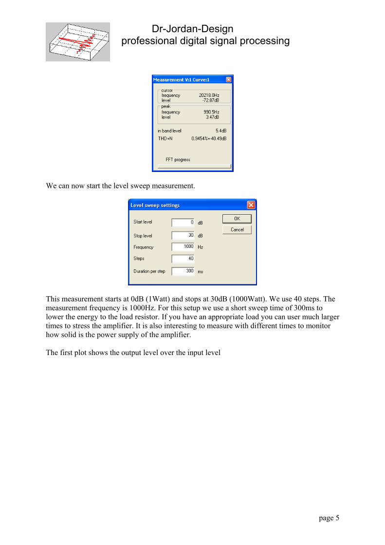
We can now start the level sweep measurement.
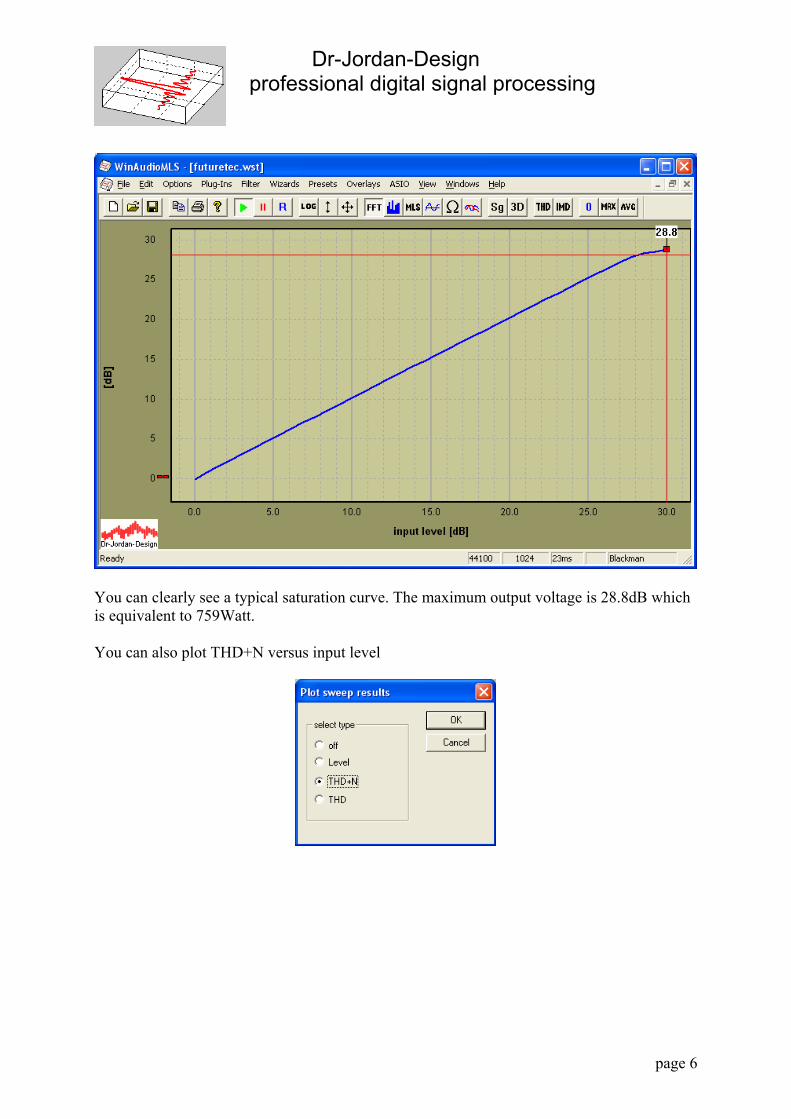
This measurement starts at 0dB (1Watt) and stops at 30dB (1000Watt). We use 40 steps. The measurement frequency is 1000Hz. For this setup we use a short sweep time of 300ms to lower the energy to the load resistor. If you have an appropriate load you can user much larger times to stress the amplifier. It is also interesting to measure with different times to monitor how solid is the power supply of the amplifier. The first plot shows the output level over the input level
Dr-Jordan-Design professional digital signal processing
page 6
You can clearly see a typical saturation curve. The maximum output voltage is 28.8dB which is equivalent to 759Watt. You can also plot THD+N versus input level
Dr-Jordan-Design professional digital signal processing
page 7
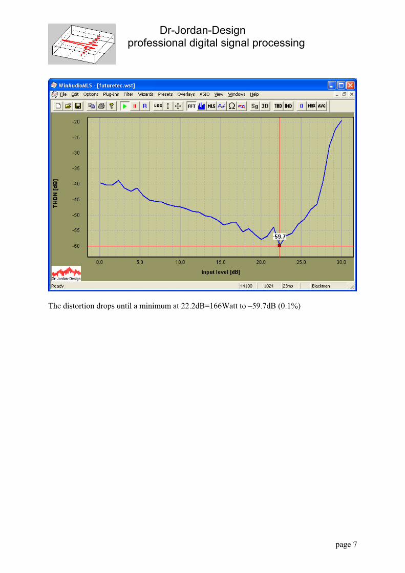
The distortion drops until a minimum at 22.2dB=166Watt to –59.7dB (0.1%)
Dr-Jordan-Design professional digital signal processing
page 8
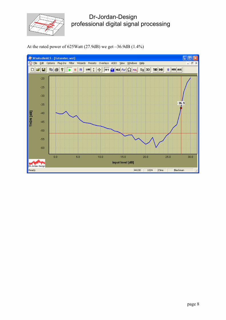
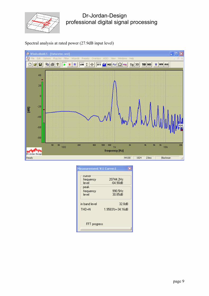
At the rated power of 625Watt (27.9dB) we get –36.9dB (1.4%)
Dr-Jordan-Design professional digital signal processing
page 9
Spectral analysis at rated power (27.9dB input level)

Dr-Jordan-Design professional digital signal processing
page 10
Frequency response The following picture shows the measured frequency response. Output power is 1Watt @4Ohm. Cut-off frequency with –3dB is 20kHz.
Dr-Jordan-Design professional digital signal processing
page 11
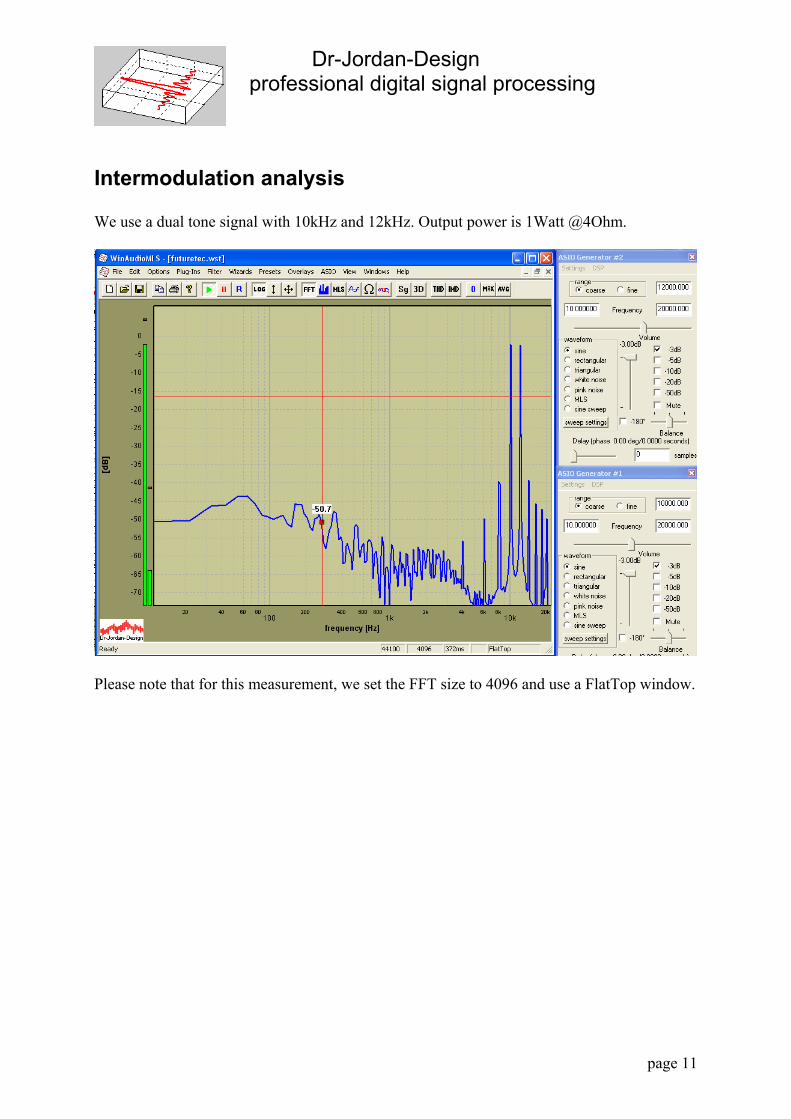
Intermodulation analysis We use a dual tone signal with 10kHz and 12kHz. Output power is 1Watt @4Ohm.
Please note that for this measurement, we set the FFT size to 4096 and use a FlatTop window.
Dr-Jordan-Design professional digital signal processing
page 12
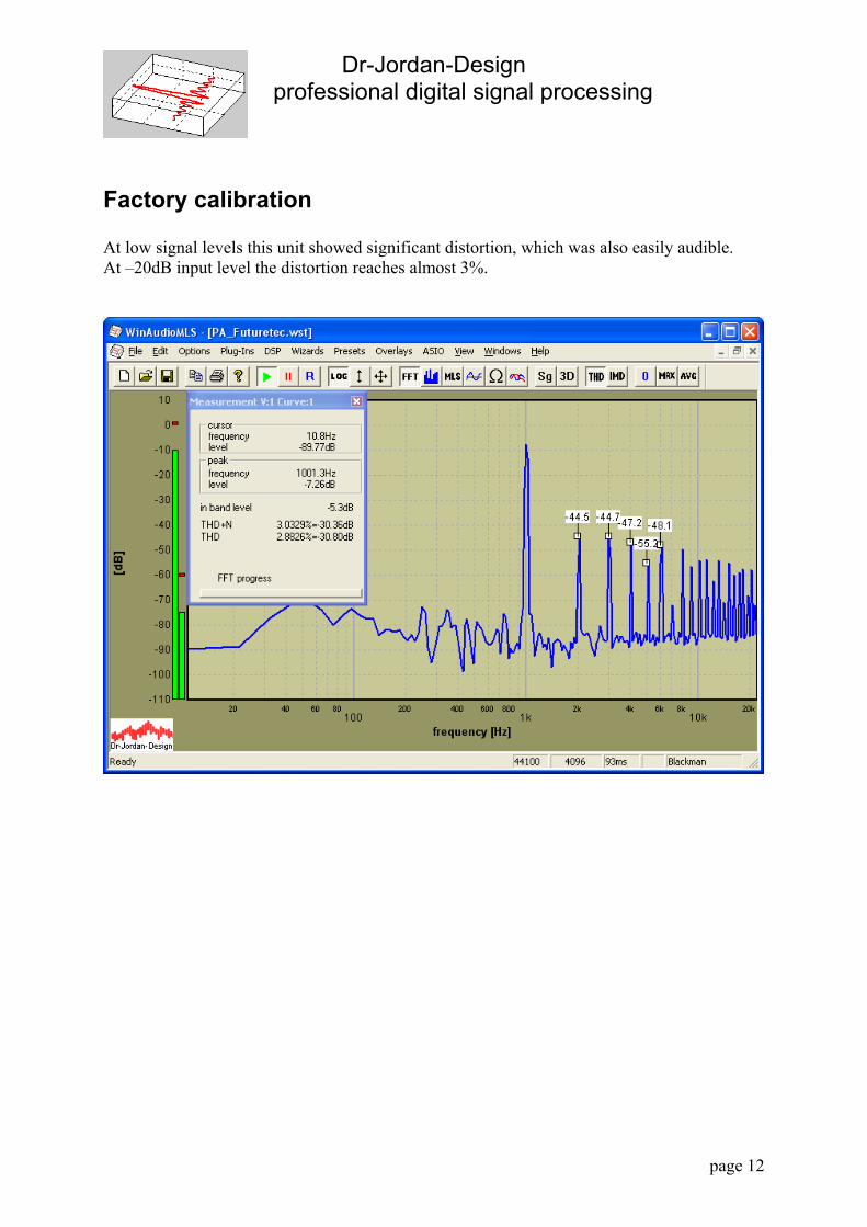
Factory calibration At low signal levels this unit showed significant distortion, which was also easily audible. At –20dB input level the distortion reaches almost 3%.
Dr-Jordan-Design professional digital signal processing
page 13
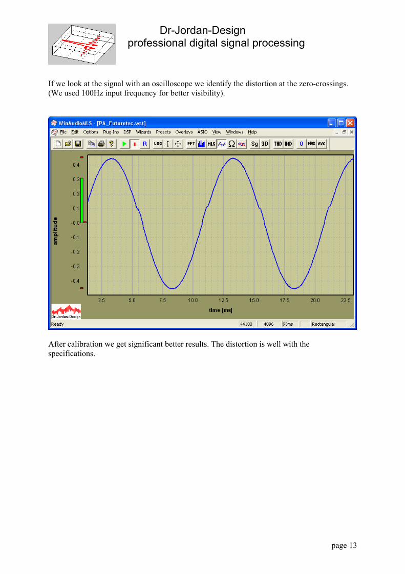
If we look at the signal with an oscilloscope we identify the distortion at the zero-crossings. (We used 100Hz input frequency for better visibility).
After calibration we get significant better results. The distortion is well with the specifications.
Dr-Jordan-Design professional digital signal processing
page 14
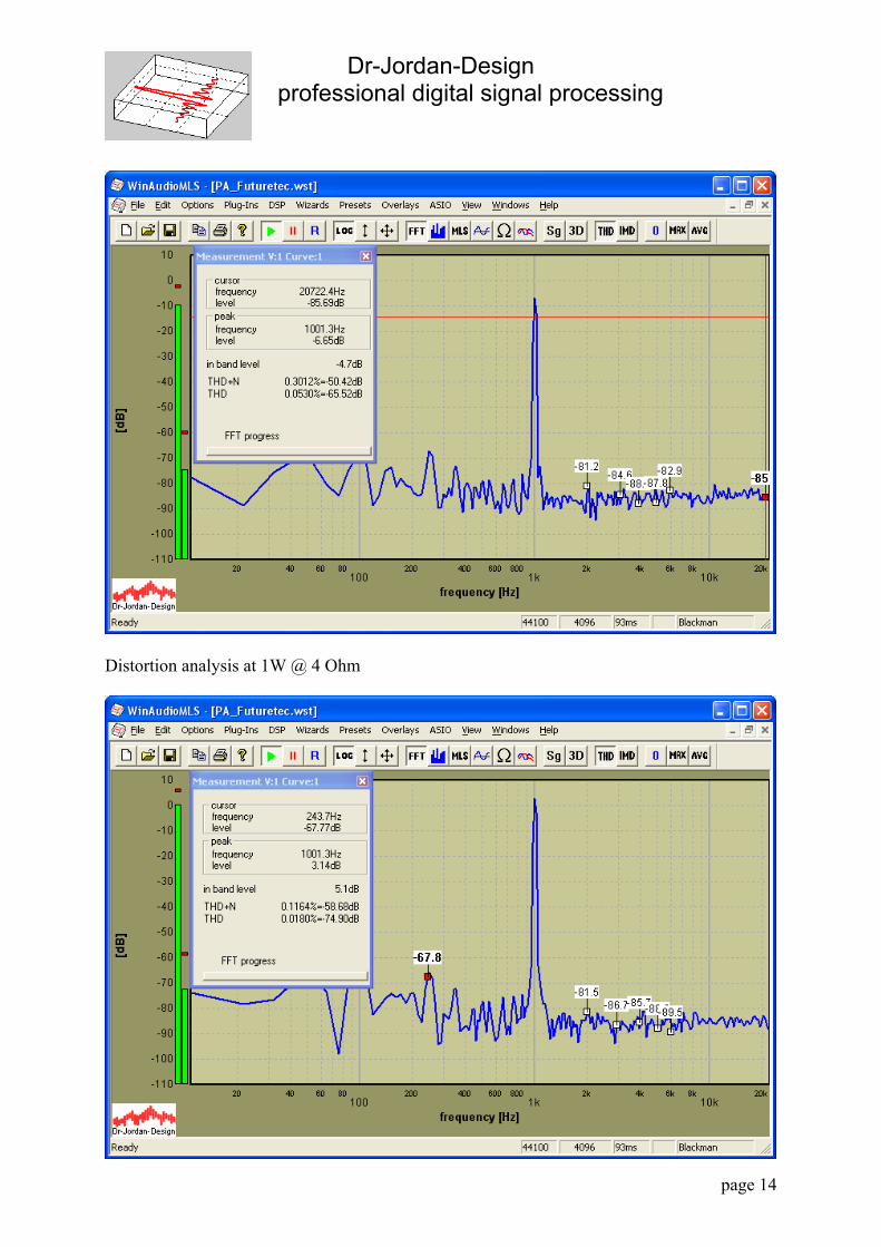
Distortion analysis at 1W @ 4 Ohm
Dr-Jordan-Design professional digital signal processing
page 15
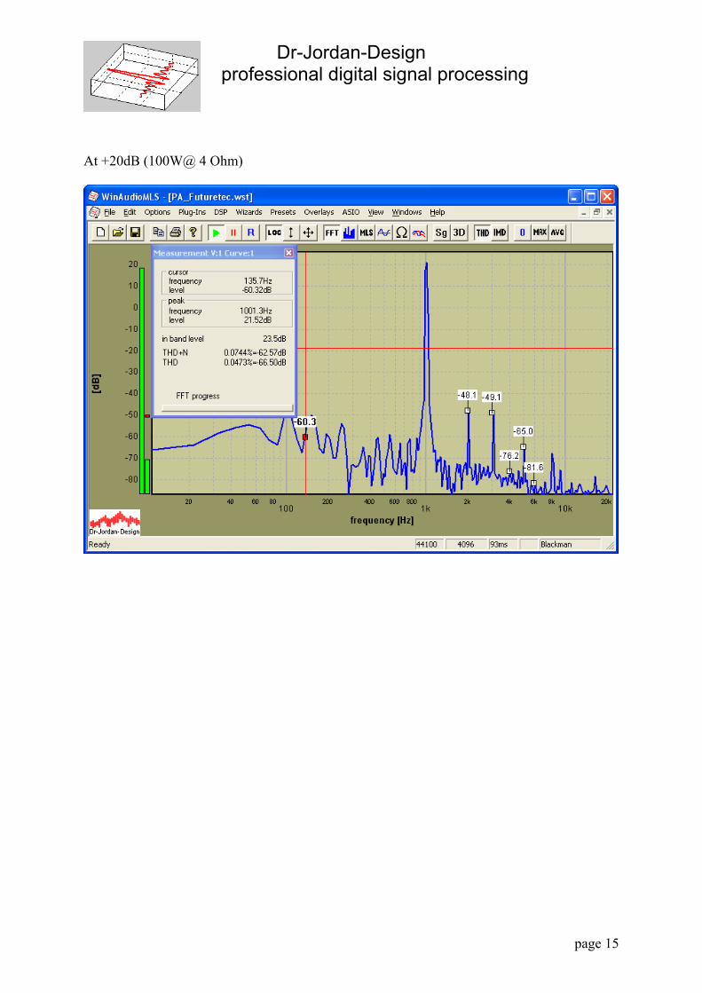
At +20dB (100W@ 4 Ohm)

Dr-Jordan-Design professional digital signal processing
page 16
At +27dB 500W @ 4 Ohm
Summary This power amplifier reaches the specified output power. But the distortion is high, especially for lower levels, which is typical for such simple circuit design. This unit was basically not factory calibrated. After calibration we get significant better results, which are well with the specification.