warning caution and advisory lights; avionics systems ... systems harmonization working group ......
TRANSCRIPT

Federal Aviation Administration – Regulations and PoliciesAviation Rulemaking Advisory Committee Transport Airplane and Engine Issue Area Avionics Systems Harmonization Working Group Task 4 – Warning Caution and Advisory Lights

Task Assignment

[Federal Register: April 23, 2002 (Volume 67, Number 78)] [Notices] [Page 19796-19797] From the Federal Register Online via GPO Access [wais.access.gpo.gov] [DOCID:fr23ap02-119] ----------------------------------------------------------------------- DEPARTMENT OF TRANSPORTATION Federal Aviation Administration Aviation Rulemaking Advisory Committee; Transport Airplane and Engine Issues--New Task AGENCY: Federal Aviation Administration (FAA) (DOT). ACTION: Notice of new task assignment for the Aviation Rulemaking Advisory Committee (ARAC). ----------------------------------------------------------------------- SUMMARY: The FAA assigned four new tasks to the Aviation Rulemaking Advisory Committee to develop recommendations that will broaden current regulations and advisory material to include state-of-the-art flightdeck displays and new technologies to aid flight crewmembers in decision making. This notice is to inform the public of this ARAC activity. FOR FURTHER INFORMATION CONTACT: Mike Kaszycki, Federal Aviation Administration, Northwest Mountain Region Headquarters, 1601 Lind Avenue, SW., Renton, Washington, 98055; telephone: 425-227-2137; fax: 425-277-1320; e-mail: [email protected]. SUPPLEMENTARY INFORMATION: Background Problem Title 14 Code of Federal Regulations Sec. 25.1322 describes standards for the color of warning, caution, advisory, and other message lights that are installed as annunciation displays in the flightdeck. It addresses visual alerting cues only in the form of colored lights installed in the flightdeck. The regulation became effective February 1 1977 (Amendment No. 25-38, 41 FR 44567, December 20, 1976) and has never been amended. It does not consider the use of corresponding aural tones/voice and prioritization of multiple alerts that may occur at the same time. Nor, does it consider new technologies, other than colored lights, that may be more effective in aiding the flightcrew in decision making. Further, Sec. 25.1322 is outdated, does not address safety concerns associated with today's display systems, and has resulted in additional work for applicants when showing compliance, and for the FAA when addressing new flightdeck designs and the latest display technologies via special conditions and issue papers.

Advisory Circular (AC) 25-11, Transport Category Airplane Electronic Display Systems, contains guidance for demonstrating compliance with Sec. 25.1322. The scope of the AC, which was published July 16, 1987, is limited and pertains strictly to cathode ray tube (CRT) based electronic display systems used for guidance, control, or decision making by the flightcrew. The guidance is clearly outdated in view of the computer-based and other advanced technological instruments used in transport category airplanes today. Any rule or advisory circulars that results from this action would affect all new transport airplanes that are certified to part 25/Joint Aviation Requirements 25 (JAR-25). Both the FAA and industry agree that Sec. 25.1322 is not appropriate for the current or future flightdeck design and the technologies associated with visual and aural annunciations to the flightcrew. This outdated regulation results in a potentially significant effect on airplane design, product design and technical standard orders, system integration, airplane type certifications and supplemental type certifications, costs associated with certifications, and flightcrew operation on airplane safety. Tasking Statement For the problem described above, the FAA tasked the ARAC \1\ to: 1. Review and recommend revisions Sec. 25.1322 that are necessary to bring the safety standards up-to-date; make the standards more appropriate for addressing current and future flightdeck design and technologies associated with visual and aural annunciation; and address prioritization of multiple alerts that may occur at the same time. At a minimum, the recommendations must consider airworthiness, safety, cost, recent certification and fleet experience, and harmonization of JAR 25.1322. --------------------------------------------------------------------------- \1\ In 1992, the FAA established the ARAC to provide advice and recommendations to the FAA Administrator on the agency's rulemaking activities with respect to aviation-related issues. This includes obtaining advice and recommendations on the FAA's commitments to harmonize Title 14 of the Code of Federal Regulations (14 CFR) with its partners in Europe and Canada. --------------------------------------------------------------------------- 2. Review the existing Advisory Circular Joint (ACJ) 25.1322 and determine if a harmonized AC 25.1322 should be developed. 3. Identify any rules or advisory circulars that may conflict with the revised rule to determine if changes should be developed and address the proposed changes to Secs. 25.1309 and 25.1329 that pertain to alerting. 4. Recommend revisions to AC 25-11 and ACJ 25-11. a. Review AC 25-11 and ACJ 25-11 to develop harmonized advisory material. The harmonized guidance material may be significantly different from the existing material, but it must not conflict with the harmonized Sec. 25.1322 standard. b. Coordinate with other harmonization working groups in revising the advisory material. The Human Factors HWG is currently working a similar activity and should be consulted to ensure that any revised material has appropriate input and influence from the human factors

discipline. Review and revision of the powerplant-related sections of AC 25-11 should be delegated to the Powerplant Installation HWG. The Flight Test HWG should review the flight test related sections. c. Prepare a ``user needs analysis'' that addresses some unique requirements that are not fully met by the current guidance. (For example, manufacturers and installers of liquid crystal display based systems are considered ``users'' whose needs may not currently be met.) d. Review other advisory circulars (such as AC's/ACJ's for various systems) and other industry documents to understand their relevance to AC 25-11. Additionally, recent industry activities have produced materials (for example, Aviation Recommended Practices) that may be useful in developing the harmonized AC. e. Recommend a format of the advisory circulars that can accommodate future changes. The current AC/ACJ format is not conducive to additions as new systems are developed, new functions are identified, and new technologies are employed. The revised harmonized AC/ACJ should be formatted to accommodate future changes. For each task, ARAC is to review airworthiness, safety, cost, and other relevant factors, including recent certification and fleet experience. ARAC will submit a report to the FAA (format and content to be determined by the FAA) that recommends revisions to the regulation, including cost estimates, and outlines the information and background for the advisory circulars. If a notice of proposed rulemaking or notices of proposed advisory circulars are published for public comment as a result of the recommendations, ARAC may be further asked to review all comments received and provide the FAA with a recommendation for disposition of public comments for each project. [[Page 19797]] Schedule: The report and draft advisory circular is to be completed no later than 24 months after the FAA publishes the tasks in the Federal Register. ARAC Acceptance of Tasks ARAC accepted and assigned the task to the Avionics Systems Harmonization Working Group. The working group serves as staff to ARAC and assists in the analysis of the assigned task. ARAC must review and approve each working group's recommendations. If ARAC accepts the working group's recommendations, it will forward them to the FAA. Recommendations that are received from ARAC will be submitted to the agency's Rulemaking Management Council to address the availability of resources and prioritization. Working Group Activity The Avionics System Harmonization Working Group must comply with the procedures adopted by ARAC. As part of the procedures, the working group must: 1. Recommend a work plan for completing each task, including the rationale supporting such a plan for consideration at the October 15- 16, 2002, meeting of the ARAC on transport airplane and engine issues. 2. Give a detailed conceptual presentation of the proposed recommendations before proceeding with the work stated in item 3. 3. Draft the appropriate documents and required analyses and/or any

other related materials or documents. 4. Provide a status report at each ARAC meeting on transport airplane and engine issues. Participation in the Working Group The Avionics Systems Harmonization Working Group is composed of technical experts having an interest in the assigned tasks. A working group member need not be a representative or a member of the full committee. An individual who has expertise in the subject matter and wishes to become a member of the working group should write to the person listed under the caption FOR FURTHER INFORMATION CONTACT expressing that desire, describing his or her interest in the task, and stating the expertise he or she would bring to the working group. All requests to participate must be received no later than (1 month after publication of the tasking statement). The requests will be reviewed by the assistant chair, the assistant executive director, and the working group co-chairs. Individuals will be advised whether their request can be accommodated. Individuals chosen for membership on the working group must represent their aviation community segment and actively participate in the working group (e.g., attend all meetings, provide written comments when requested to do so, etc.). They must devote the resources necessary to support the working group in meeting any assigned deadlines. Members are expected to keep their management chain and those they may represent advised of working group activities and decisions to ensure the proposed technical solutions do not conflict with their sponsoring organization's position when the subject being negotiated is presented to ARAC for approval. Once the working group has begun deliberations, members will not be added or substituted without the approval of the assistant chair, the assistant executive director, and the working group co-chairs. The Secretary of Transportation determined that the formation and use of the ARAC is necessary and in the public interest in connection with the performance of duties imposed on the FAA by law. Meetings of the ARAC will be open to the public. Meetings of the Avionics Systems Harmonization Working Group will not be open to the public, except to the extent that individuals with an interest and expertise are selected to participate. The FAA will make no public announcement of working group meetings. Issued in Washington, DC, on April 11, 2002. Anthony F. Fazio, Executive Director, Aviation Rulemaking Advisory Committee. [FR Doc. 02-9947 Filed 4-22-02; 8:45 am] BILLING CODE 4910-13-M

Recommendation Letter

Pratt & Whitney 400 Main Street East Hartford, Connecticut 06108
May 14, 2004 Federal Aviation Administration 800 Independence Avenue SW Washington, D.C. 20591 Attention: Mr. Nicholas Sabatini, Associate Administrator for Regulation and Certification Subject: ARAC Recommendations, 14 CFR 25.1322 Reference: ARAC Tasking, Federal Register, dated April 23, 2002 Dear Nick, The Transport Airplane and Engine Issues Group is pleased to submit the following as a recommendation to the FAA in accordance with the reference tasking. The Avionics Systems Harmonization Working Group has prepared this information. ASHWG Report – 14 CFR 25.1322 The TAEIG unanimously accepted the ASHWG report. During the discussion, the industry representatives on TAEIG felt that when considering the acceptability of these colors for graphical weather depiction, the potential safety benefits should be considered during the certification process. Sincerely yours,
Craig R. Bolt Assistant Chair, TAEIG [email protected] (Ph: 860-565-9348/Fax: 860-557-2277) Copy: Dionne Krebs – FAA-NWR Mike Kaszycki – FAA-NWR Alicia Douglas – FAA-Washington, D.C. Clark Badie - Honeywell

Acknowledgement Letter

SEP 2 0 2004
Mr. Craig R. Bolt Assistant Chair, Aviation Rulemaking
Advisory Committee Pratt & Whitney 400 Main Street, Mail Stop 162-14 East Hartford, CT 06108
Dear Mr. Bolt:
This letter acknowledges receipt of several letters that you sent for the Avi~tion Rulemaking Advisory Committee (ARAC) on Transport Airplane and Enginf (TAE) Issues. 1,
Date of Description of Recommendation Working Group Letter
01/06/2003 Proposed rule and draft advisory material on bird Engine Harmonization ingestion capability (§ 33. 76) Workin~ I Group (HWG)
10/22/2003 Final report and position statements on bird strike Genera Structures requirements (§ 25.631) HWG
10/22/2003 Final report and draft advisory material on alterna- Genera Structures tive composite structure material (§ 25.603) HWG
I
05/14/2004 Final report, proposed rule language, and draft Avionic~ Systems HWG advisory material on warning, caution, and advi- I
I
sory alerts installed in the cockpit (§ 25.1322) I !
06/17/2004 Final repo~ and draft advisory material on fire pro- Loads •rd Dynamics tection of flight controls, engine mounts and other HWG flight structures (§ 25.865)
06/22/2004 Final report, proposed rule, and draft advisory ma- Human i:actor HWG terial on installed systems and equipment for use by the flight crew (§ 25.1302)
I wish to thank the ARAC and the working groups for the resources that ind i.Jstry gave to develop these recommendations. The recommendations from the, ~vionics Systems HWG, the Human Factor HWG, and the Loads and Dynamics H\/v Gwill remain open until these working groups complete a Phase 4 review. The rE maining recommendations have been closed, as we consider submittal of the report $ as completion of the tasks. All of these recommendations will be placed on thi ,ARAC
. . . website at http.//www.faa.gov/avr/arm/arac/mdex.cfm.
tJ. (

We will continue to keep you apprised of our efforts on the ARAC recomm¢mdations and the rulemaking prioritization at the regular ARAC TAE issues meetings.
I
Sincerely,
Original Signed By Margaret Gilligan
Nicholas A. Sabatini Associate Administrator for Regulation
and Certification
cc: ARM-1/20/200/204/207; AIR-100, ANM-110
ARM-207:Jlinsenmeyer:fs:8/12/04:PCDOCS # 21644 Control Nos. 20041855-0; 20041944-0; 20042001-0
2

Recommendation

ARAC WG Report FAR/JAR 25.1322 & AC/ACJ 25.1322
1. What is underlying safety issue addressed by the FAR/JAR?
The rule provides color requirements for warning, caution and advisory lights associated with alerting functions. However, the current rule only addresses “lights” and does not take into consideration the implementations, technology, and associated safety issues with the latest flight deck alerting systems. FAR/JAR 25.1322 describes standards for the color of warning, caution, advisory, and other message lights that are installed as annunciation displays in the flight deck. It addresses visual alerting cues only in the form of colored lights installed in the flight deck. The regulation became effective February 1, 1977 (Amendment No. 25-38, 41 FR 44567, December 20, 1976) and has never been amended. It does not consider the use of corresponding aural tones/voice and prioritization of multiple alerts that may occur at the same time. Nor does it consider new technologies, other than colored lights, that may be more effective in aiding the flight crew in decision making. Further, FAR/JAR 25.1322 is outdated, does not address safety concerns associated with today’s display systems, and has resulted in additional work for applicants when showing compliance, and for the FAA when addressing new flight deck designs and the latest display technologies via special conditions and issue papers.
2. What are the current FAR and JAR standards? Current FAR text: If warning, caution, or advisory lights are installed in the cockpit, they must, unless otherwise approved by the Administrator, be-- (a) Red, for warning lights (lights indicating a hazard which may require immediate corrective action); (b) Amber, for caution lights (lights indicating the possible need for future corrective action); (c) Green for safe operation lights; and (d) Any other color, including white, for lights not described in paragraphs (a) through (c) of this section, provided the color differs sufficiently from the colors prescribed in paragraphs (a) through (c) of this section to avoid possible confusion. Current JAR text: If warning, caution, or advisory lights are installed in the cockpit, they must, unless otherwise approved by the Authority, be - (a) Red, for warning lights (lights indicating a hazard which may require immediate corrective action); (b) Amber, for caution lights (lights indicating the possible need for future corrective action); (c) Green, for safe operation lights; and (d) Any other colour, including white, for lights not described in sub-paragraphs (a) to (c) of this paragraph, provided the colour differs sufficiently from the colours prescribed in sub-paragraphs (a) to (c) of this paragraph to avoid possible confusion.
3. What are the differences in the standards and what do these differences result in?:
There are no differences in the standards. There is a related AMJ, but no AC.
4. What, if any, are the differences in the means of compliance? Specific means of compliance to JAR 25.1322 are provided in the associated AMJ. No specific means of compliance exists for FAR 25.1322.

5. What is the proposed action? The FAR 25 and JAR 25 and their associated guidance material have been identified as lacking content and guidance commensurate with the state-of-the-art. Therefore, a new FAR/JAR 25.1322 will be written to address current or future flight deck design and the technologies associated with flight crew alerting. The existing AMJ will be reviewed and harmonized advisory material will be generated.
6. What should the harmonized standard be?
A new FAR/JAR 25.1322 and associated AC/AMJ 25.1322. (See Attachment and file Draft AC25.1322 DC Meeting 1003_rev a)
7. How does this proposed standard address the underlying safety issue (identified under #1)?
The new standard will address the requirements for crew alerting systems and provide content and guidance that is commensurate with the state-of-the-art flight deck alerting systems.
8. Relative to the current FAR, does the proposed standard increase, decrease, or maintain the
same level of safety? The level of safety will be increased by providing new standards and guidance material that is commensurate with the state-of-the-art and crew alerting, and by providing guidance for other Part 25 regulations that require the use of alerting.
9. Relative to current industry practice, does the proposed standard increase, decrease, or
maintain the same level of safety? The new standards and guidance material supports current industry practice and will increase the level of safety.
10. What other options have been considered and why were they not selected?: The group initially thought of adopting the JAR and associated AMJ. However, this was still
deemed insufficient for today’s flight deck alerting systems. The level of effort to rewrite the rule was significant, and each sub-paragraph was reviewed and many options were considered. In addition, the Human Factors Harmonization Working Group provided additional options for consideration. The group has modified wording in the draft AC/ACJ to address the means of compliance to sub paragraph e) in the rule. 11. Who would be affected by the proposed change? The (Part 25) aviation industry in
general including aircraft manufacturers, aircraft operators, avionics manufacturers, and regulators, if they are not already practicing the essence of these standards. There may be indirect effect to manufacturers that wish to develop products and systems that are intended to cross part 23/25/27/29 applications.
12. To ensure harmonization, what current advisory material (e.g., ACJ, AMJ, AC, policy letters)
needs to be included in the rule text or preamble? AC/AMJ 25-11, and parts of the draft AC/AMJ 25-1322.
13. Is existing FAA advisory material adequate? No. There is no existing FAA
advisory material. However, there is an existing AMJ 25.1322 and that document has been revised to incorporate this latest information.
14. How does the proposed standard compare to the current ICAO standard?
There are no applicable ICAO standards. 15. Does the proposed standard affect other HWGs? Yes. We have coordinated with the
working groups responsible for Human Factors (25.1301(e)), Propulsion and Safety (25.1309). We have also coordinated with other industry groups such as the RTCA SC-195 committee.

16. What is the cost impact of complying with the proposed standard?
For those manufacturers that are already in compliance / already practicing. Harmonization of 25.1322 and the associated guidance material will significantly reduce certification costs, thereby improving the allocation of limited resources. For those manufacturers that are not in compliance/not already practicing, there may be additional costs to comply with the new rule. There is a general potential problem with the change process, if this revised rule is used for new applications of existing products and systems, or if this revised rule is applied to any modifications to existing products and systems.
17. Does the HWG want to review the draft NPRM at “Phase 4” prior to publication in the Federal
Register? Yes
18. In light of the information provided in this report, does the HWG consider that the “Fast Track”
process is appropriate for this rulemaking project, or is the project too complex or controversial for the Fast Track Process?
Yes, it is appropriate for the “Fast Track” process. The group identified an issue regarding sub paragraph (e) in the draft rule that caused controversy. The group resolved this to our satisfaction by revising both the regulation and advisory material, based on comments received from the RTCA SC-195 committee and from within group membership. The AVHWG will also update AC/AMJ 25-11 to cover the broad scope of the use of colors in the flight deck.

FAR/JAR 25.1322 Flight Crew Alerting
(a) When flight crew alerts are provided they must:
1) Provide timely attention-getting cues through at least two different senses by combination of aural, visual, or tactile indications, for crew alerts requiring immediate flight crew awareness.
2) Provide the flight crew with the information needed to identify the alert and determine correct action, if any.
3) Be readily and easily detectable and intelligible by the flight crew under all foreseeable operating conditions including conditions where multiple alerts are provided.
(b) Alerts must conform to the following prioritization hierarchy based upon urgency of flight crew awareness and urgency of flight crew response.
1) Warning: For conditions that require immediate flight crew awareness and immediate flight crew response. If warnings are time critical to maintain the immediate safe operation of the airplane, they must be prioritized higher than other warnings.
2) Caution: For conditions that require immediate flight crew awareness and subsequent flight crew response.
3) Advisory: For conditions that require flight crew awareness and may require subsequent flight crew response.
(c) Alert presentation means must be designed to minimize nuisance effects. In particular a crew alerting system must:
1) Permit each occurrence of attention getting cues, if provided, to be acknowledged and suppressed unless they are otherwise required to be continuous.
2) Prevent the presentation of an alert that is inappropriate or unnecessary for the particular phase of operation.
3) Remove the presentation of the alert when the condition no longer exists
4) Provide a means to suppress an attention getting component of an alert caused by a failure of the alerting system, and/or the sensors, which interfere with the flight crew’s ability to safely operate the aircraft. This means must not be readily available to the flight crew such that it could be operated inadvertently, or by habitual reflexive action. In this case, there must be a clear and unmistakable annunciation to the flight crew that the alert has been suppressed.
(d) Alerts must conform to the following color convention for visual alert indications:
1) Red for Warning alert indications.
2) Amber/yellow for Caution alert indications.
3) Any color except red or green for Advisory alert indications. (e) The colors red and amber/yellow are normally reserved for alerting functions. The use of these colors for functions other than crew alerting must be limited and must not adversely affect crew alerting.

Final Version AC/ACJ 25.1322 – Updated April 2004 in London. Flight Crew Alerting

Table of Contents
1. PURPOSE ................................................................................................................................ 6 2. SCOPE...................................................................................................................................... 6 3. RELATED REGULATIONS................................................................................................... 7 4. RELATED DOCUMENTS ...................................................................................................... 8
4.a Federal Aviation Administration Documents. .................................................................. 8 4.b JAA Documents................................................................................................................ 9 4.c Industry Documents.......................................................................................................... 9
5. BACKGROUND...................................................................................................................... 9 6. DEFINITIONS ......................................................................................................................... 9 7. GENERAL ............................................................................................................................. 12
7.a Alerting Presentation Elements ...................................................................................... 13 7.b Functional Components for each type of Alert.............................................................. 13 7.c Alerting System Reliability and Integrity....................................................................... 15
8. Management of AlertS............................................................................................................ 15 8.a Prioritization ................................................................................................................... 15 8.b Alert Inhibits................................................................................................................... 16 8.c Clear/Recall of visual alert messages ............................................................................. 17 8.d Considerations for interface or integration with other systems (ex. Checklist, synoptics, switches, discrete lamps)............................................................................................................................ 17 8.e Color standardization...................................................................................................... 17 8.f Suppression of False Alerts ............................................................................................ 18
9. Certification TEST and evaluation considerations ................................................................. 18 10. RETROFIT applicability .................................................................................................... 19
10.a Purpose ........................................................................................................................... 19 10.b Visual Alerts................................................................................................................... 19 10.c Aural Alerts .................................................................................................................... 20 10.d Special Considerations for Head-Up Displays (HUDs).................................................. 20
Appendix A EXAMPLES FOR THE INCLUSION OF Visual System Elements IN AN ALERTING SYSTEM ........................................................................................................................................ 22
A.1 Master Visual.................................................................................................................. 22 A.2 Visual Information.......................................................................................................... 23 A.3 Time Critical Warning Visual Information .................................................................... 25 A.4 Failure Flags ................................................................................................................... 25
Appendix B EXAMPLES FOR INCLUSION OF Aural System Elements IN AN ALERTING SYSTEM........................................................................................................................................................ 26
B.1 Master Aural Alert and Unique Tones............................................................................ 26 B.2 Voice Information .......................................................................................................... 28
PURPOSE This advisory circular (AC) provides guidance for the design and approval of flight crew Alerting Functions installed in transport category airplanes. SCOPE This advisory circular applies to the installation, integration, and certification of flight deck alerting systems, whether they are integrated or not. That is, it applies to individual aircraft systems that provide alerts that may or may not be integrated with a central alerting system, as well as systems whose primary function is alerting, such as a central alerting system. The alerting system may be approved as part of a TC/STC/ATC/ASTC.

This AC provides guidance as to what is considered an alert. However, what should be alerted to the flight crew is dependent on the specific design and overall flight deck philosophy. For example, the failure of a single sensor in a multi-sensor system in some cases may not necessarily result in an alert condition that the pilot needs to be aware of. However, for a single sensor system such a failure would certainly result in alert. Thus, the applicant should discuss the overall flight deck design and alerting philosophy with the Authority when determining what should be alerted to the flight crew. Any system that provides an alert should follow the guidance in this AC. Like all AC material, this AC is not mandatory and does not constitute a regulation. It is issued to provide guidance and to outline a method of compliance with rules and in particular 25.1322. RELATED REGULATIONS
The following list of regulations describe requirements for flight crew alerting for which this advisory circular provides guidance. CFR/JAR 25.207 Stall warning CFR/JAR 25.253(a)(2) High-speed characteristics CFR/JAR 25.672(a) Stability Augmentation… CFR/JAR 25.679(a) Control system gust locks CFR/JAR 25.703 Takeoff warning system CFR/JAR 25.729(e) Retracting mechanism CFR/JAR 25.783(e) Doors CFR/JAR 25.812(f)(2) Emergency lighting CFR/JAR 25.819(c) Lower deck service compartments CFR/JAR 25.841(b)(6) Pressurized cabins CFR/JAR 25.854(a) Lavatory fire protection CFR/JAR 25.857(b)(3) Cargo compartment classification CFR/JAR 25.857(c)(1) Cargo compartment classification CFR/JAR 25.857(e)(2) Cargo compartment classification CFR/JAR 25.859(e)(3) Combustion heater fire protection CFR/JAR 25.863(c) Flammable fluid fire protection CFR/JAR 25.1019(a)(5) Oil strainer or filter CFR/JAR 25.1165(g) Engine ignition systems CFR/JAR 25.1203(b)(2) CFR/JAR 25.1203(b)(3) Fire-detector system CFR/JAR 25.1203(f)(1) Fire-detector system CFR/JAR 25.1303(c)(1) Flight and navigation instruments CFR/JAR 25.1305(a)(1) CFR/JAR 25.1305(a)(5) Powerplant instruments CFR/JAR 25.1305(c)(7) Powerplant instruments CFR/JAR 25.1309(c) Equipment, systems, and installations CFR/JAR 25.1309(d)(4) Equipment, systems, and installations CFR/JAR 25.1322 Warning, caution, and advisory lights CFR/JAR 25.1326 Pitot heat indication systems CFR/JAR 25.1331(a)(3) Instruments using a power supply CFR/JAR 25.1353(c)(6)(ii) Electrical equipment and installations CFR/JAR 25.1419(c) Ice protection CFR/JAR 25.1517(3) Rough air speed, VRA CFR/JAR 25, Appendix I Section 25.6 Installation of an Automatic Takeoff Thrust Control System (ATTCS) Powerplant Instruments CFR/JAR 33.71(b)(6) Lubrication system. CFR/JAR 91.219 Altitude alerting system or device: Turbojet powered civil airplanes CFR/JAR 91.221 Traffic alert and collision avoidance system equipment and use

CFR/JAR 91.223 Terrain awareness and warning system CFR/JAR 91.603 Aural speed warning device CFR/JAR 91, Appendix A Section 91.2(b)(1) Required instruments and equipment CFR/JAR, Appendix G Section 91.2(c)(3) Operations in Reduced Vertical Separation Minimum (RVSM) Airspace - Aircraft approval CFR/JAR 91, Appendix G Section 91.3(c)(6) Instruments and Equipment Approval CFR/JAR 121.221(c)(1) Fire precautions CFR/JAR 121.221(d)(1) Fire precautions 14 CFR 121.221(f)(2) Fire precautions 14 CFR 121.289 Landing gear: Aural warning device. 14 CFR 121.307(k) Engine instruments 14 CFR 121.308(a) Lavatory fire protection. 14 CFR 121.319(b) Crewmember interphone system 14 CFR 121.354 Terrain awareness and warning system 14 CFR 121.356(b) Traffic alert and collision avoidance system CFR/JAR 121.358 Low-altitude windshear system equipment requirements CFR/JAR 121.360(a) CFR/JAR 121.360(e) CFR/JAR 121.360(f) Ground proximity warning-glide slope deviation alerting system CFR/JAR 125.187 Landing gear: Aural warning device. CFR/JAR 125.205(d) Equipment requirements: Airplanes under IFR. CFR/JAR 125.221(a) Traffic alert and collision avoidance system CFR/JAR 135.150(b)(7) Public address and crewmember interphone system 14 CFR 135.153(a) Ground proximity warning system. 14 CFR 135.154 Terrain awareness and warning system 14 CFR 135.163(d) Equipment requirements: Aircraft carrying passengers under IFR. 14 CFR 135.180(a) Traffic alert and collision avoidance system 14 CFR 135, Appendix A Section A135.1 Additional Airworthiness Standards for 10 or More Passenger Airplanes
RELATED DOCUMENTS Only those sets of materials that were used as reference for this AC/AMJ are listed. 1.a Federal Aviation Administration Documents.
(1) Report DOT/FAA/RD-81/38, II, Aircraft Alerting Systems Standardization Study, Volume II, Aircraft Alerting Systems Design Guidelines. This document can be obtained from the National Technical Information Service, Springfield, Virginia 22166
(2) AC 25-11, Transport Category Airplane Electronic Display Systems 7/16/87
(3) Report DOT/FAA/CT-96/1 - GAMA Report No 10, “Recommended Guidelines for Part 23
Cockpit/Flight Deck Design” (September 2000), Section 4, Definitions, Primary Field of View.
(4) AC 25-23 TAWS Terrain Awareness and Warning Systems

(5) AC 25-1309-1A System Design and Analysis (6) TSO C-151a, Terrain Awareness and Warning Systems (7) AC 25.1523-1, Minimum Flight Crew & Workload
1.b JAA Documents.
(1) AMJ 25.1322, Alerting Systems, dated 12 April, 1991 (2) AMJ 25.1309 System Design and Analysis (3) AMJ 25-11, Electronic Display Systems
(4) Patterson, R.D. (1982). Guidelines for Auditory Warning Systems on Civil Aircraft. Cheltenham, England: Civil Aviation Authority paper 82017.
1.c Industry Documents.
1. Edworthy, J. and Adams, A. (1996). Warning Design: A Research Perspective. Bristol, PA: Taylor & Francis.
2. Kuchar, J.K. (1996). Methodology for alerting-system performance evaluation. Journal of Guidance, Control, and Dynamics. 19, 438-444.
3. Parasuraman, R., & Riley, V. (1997). Human and Automation: use, misuse, disuse, abuse. Human Factors, 39, 216-229.
4. Satchell, P. (1993). Cockpit monitoring and alerting systems. Aldershot, England: Ashgate.
5. SAE ARP 4033 (Pilot-System Integration), August 1995 BACKGROUND In the past airplanes have been designed with discrete lights for the alerting function. Now the alerting functions can be integrated with other systems, including electronic display systems, and aural warning or tone generation systems. This AC addresses the aspects of integration including prioritization, commonality between types of alerts, competing simultaneous aural and visual alerts, correlation of aural and visual alerts, potential inhibiting of alerts, and the increased possibility of false or nuisance alerts. FAR/JAR Part 25 Regulations and advisory material often provide references to an alert, such as a warning, to provide awareness of a certain condition that is relevant to the applied rule. Many of these rules were written without recognition of a consistent flight deck alerting philosophy, and may use the term “warning” in a generic sense. This AC/ACJ does not intend to conflict with or replace the intent of those rules, but it is meant to provide standardization of crew alerting terminology that may be used in the development of consistent regulations and advisory material, and consistency to show compliance to existing rules. DEFINITIONS Definitions are written to support the content of this AC and its associated rule. Other regulations may use terms such as “warning” in a manner that is not necessarily consistent with the definitions below. However, the intent of this section is to facilitate standardization of these terms.
Advisory The level of alert for conditions that require flight crew awareness and may require subsequent flight crew response Alert

A generic term used to describe a flight deck indication meant to attract the attention of and identify to the flight crew a non-normal operational or airplane system condition. Warnings, Cautions, and Advisories are considered to be alerts. Alert Inhibit Application of specific logic to prevent the presentation of the alert. Alert Message A visual alert comprised of text, usually presented on a flight deck display. Alerting Function The aircraft function that provides alerts to the flight crew for non-normal operational or airplane system conditions. This includes Warning, Caution and Advisory information. Alerting Philosophy The principles, guidance and rules for implementing alerting functions within a flight deck. These typically consider:
• The reason for implementing an alert • The level of alert required for a given condition • The characteristics of each specific alert • Integration of multiple alerts
Attention Getting Cues Perceptual signals (visual, auditory or tactile/haptic) designed to attract the flight crew’s attention in order to obtain the immediate awareness that an alert condition exists. Caution The level of alert for conditions that require immediate flight crew awareness and subsequent flight crew response. Collector Message An alert message that replaces two or more related alert messages that do not share a common cause or effect. Example: A Doors alert collector message is displayed when more than one entry, cargo, or service access door is open at the same time. Communication message A type of message whose initiating conditions are caused by incoming communications, primarily data link conditions. This type of message is not a crew alert. (1) Comm High: A communication message which requires immediate flight crew awareness and immediate flight crew response. (Note: At this time there are no communication messages defined that require immediate flight crew response.) (2) Comm Medium: An incoming communication message which requires immediate flight crew awareness and subsequent flight crew response. (3) Comm Low: An incoming communication message which requires flight crew awareness and future flight crew response. False Alert An incorrect or spurious alert caused by a failure of the alerting system including the sensor. Failure Flag One local means of indicating the failure of a displayed parameter.

Flashing Short term flashing symbols approximately 10 seconds or flash until acknowledge. Flight Crew Response The activity accomplished due to the presentation of an alert such as an action, decision, prioritization, search for additional information. Master Aural Alert An aural indication used to attract the flight crew’s attention that is specific to an alert urgency level (e.g. Warning, Caution) Master Visual Alert A visual indication used to attract the flight crew’s attention that is specific to an alert urgency level (e.g. Warning, Caution). Normal Condition Any fault-free condition typically experienced in normal flight operations. Operations typically well within the aircraft flight envelope and with routine atmospheric and environmental condition. Nuisance Alert An alert generated by a system that is functioning as designed but which is inappropriate or unnecessary for the particular condition. Primary field of view Primary Field-of-View is based upon the optimum vertical and horizontal visual fields from the design eye reference point that can be accommodated with eye rotation only. The description below provides an example of how this may apply to head-down displays. With the normal line-of-sight established at 15 degrees below the horizontal plane, the values for the vertical (relative to normal line-of-sight forward of the aircraft) are +/-15 degrees optimum, with +40 degrees up and -20 degrees down maximum. For the horizontal visual field (relative to normal line-of-sight forward of the aircraft), the values are +/-15 degrees optimum, and +/-35 degrees maximum. .

Status A specific aircraft system condition that is recognized using a visual indication, but does not require an alert and does not require flight crew response. These types of messages are sometimes used to determine airplane dispatch capability for subsequent flights. Tactile/haptic Information Indication means where the stimulus is via physical touch, force feedback or vibration (e.g. stick shaker). Time-Critical Warning A subset of warning. The highest level of warning for conditions that require immediate flight crew response, to maintain the immediate safe operation of the airplane.Examples of Time-Critical warnings are: • Predictive and Reactive Windshear Warnings • Terrain Awareness Warnings (TAWS) • TCAS Resolution Advisory • Overspeed Warnings • Low Energy Warnings Umbrella Message An alert message that is presented in lieu of two or more alert messages that share a common cause. Example: A single Engine Shutdown message in lieu of the multiple messages for electrical generator, generator drive, hydraulic pump and bleed air messages which would otherwise have been displayed. Unique Tones (Unique Sounds) An aural indication that is dedicated to specific alerts. (e.g. fire bell, overspeed) Visual Alert Information A visual indication that presents the flight crew with data on the exact nature of the alerting situation. For advisory level alerts, it also provides the awareness. Voice Information Means for informing the flight crew of the nature of a specific condition. Warning The level of alert for conditions that require immediate flight crew awareness and immediate flight crew response.
GENERAL
The purpose for alerting functions on airplanes is to get the attention of the flight crew, and inform the flight crew of specific airplane system conditions and certain operational events that require their awareness. The ability of the alerting function to accomplish its purpose is effected not only by the alert presentation itself, but also by the sensed condition and information processing for which the alert presentation was initiated. The alert presentation, condition sensing and information processing for the alert should all be designed to support the purpose of the alerting function. Only airplane system conditions and operational events that require flight crew awareness to support a flight crew response should cause an alert. Conditions and events that do not require flight crew awareness should not cause an alert.

For all alerts which are presented to the flight crew, the action or accommodation for that alert must be either intuitive or a specific procedure must be provided to assist the flight crew in accomplishing corrective or compensatory action. Appropriate flight crew action for flight crew alerts are normally defined by airplane procedures (ex: in checklists), and are trained as part of a flight crew training curriculum or considered basic airmanship. The presentation of all alerting signals should be accomplished using a consistent alerting philosophy.
1.d Alerting Presentation Elements
Alerting system presentation elements typically include: • Master Visual Alerts • Visual Alert Information • Master Aural Alerts • Voice Information • Unique Tones (Unique Sounds) • Tactile/haptic Information • Failure Flag
Logic should be incorporated to ensure that the alerting system components are coordinated and provide the proper alert presentation format for each urgency level. For example, the onset of the master visual alert should occur simultaneously with the onset of the master aural alert. When practical, the voice information message should be identical to the alphanumeric message presented on the visual information display, but at a minimum the voice and alphanumeric messages should be compatible and readily understandable. Colors used for master caution and master warning should match colors for their respective caution and warning visual alerts.
To maintain the effectiveness of voice alerting, the use of voice should be minimized. To maintain the effectiveness of the visual alerting, consistent use of the colors red and amber/yellow must be implemented throughout the flight deck. Failure flags and exceedances do not necessarily need to meet the requirements 25.1322(a)(1). For example, failure flags on primary flight displays have been shown to have sufficient attention getting characteristics and thus do not necessarily satisfy all of the requirements for crew alerts, such as providing attention-getting cues through at least two different senses.
1.e Functional Components for each type of Alert
(1) Warning:
The alerting system functional components used to accomplish the alerting and informing functions for warnings should include: • Master Visual Alert, AND
• Visual Information, AND • Master Aural Alert, or
Voice Information or unique tone Note: Voice information may be preceded by a master aural alert
It is recognized that in a limited number of cases a master visual and master aural alert may not be required. For example, visual information presented in the pilot’s primary forward

field of view may be acceptable in place of a master visual alert if it provides sufficient attention-getting characteristics. Exceptions must be evaluated on a case by case basis. The immediacy of pilot response required for some warning conditions may not be supported by use of the alerting system components described above. Examples of such warning conditions are reactive windshear warning and ground proximity warning. These are typically called “time-critical warnings.” The alerting system components used for indicating these kinds of conditions must support immediate pilot awareness of the specific condition without further reference to other indications in the flight deck. The alerting system functional components used to accomplish the alerting and informing functions for time-critical warnings should include: • Unique voice information and/or unique tone for each condition, AND • Unique visual alert information in both pilots primary forward field of view for each
condition.
Since, for time-critical warnings, it is expected that the unique visual alert information and the unique voice information or unique tone meets the attention-getting requirements for the condition, then the use of a master visual alert is not required. However, if the master visual alert is used, it should be used to aid in the overall attention-getting characteristics and to obtain the desired flight crew response and should not distract the flight crew from the time-critical condition.
2) Caution
The alerting system functional components used to accomplish the alerting and informing functions for cautions should include: • Master Visual Alert, AND • Visual Information, AND • Master Aural Alert, or
Voice Information or unique tone Note: Voice information may be preceded by a master aural alert
It is recognized that in a limited number of cases a master visual and master aural alert may not be required. For example, visual information presented in the pilot’s primary forward field of view may be acceptable in place of a master visual alert if it provides sufficient attention-getting characteristics. Exceptions must be evaluated on a case by case basis. Some caution alerts are related to conditions that are precursors to potential time-critical warning conditions. In these cases, the alerting system components associated with the caution should be consistent with the components for related time-critical warning. For example, a TCAS II Traffic condition, which can be a precursor to a TCAS II Resolution Advisory condition, may not have an associated Master Caution and is acceptable because the TCAS Traffic voice information alone provides the characteristic of a caution.
3) Advisory The alerting system functional components used to accomplish the alerting and informing functions for advisories should include:

• Visual Information - Advisory information may be located in an area where the flight crew is expected to periodically scan for information
Note: Advisory information does not require immediate flight crew awareness and therefore does not require an attention getting (master) visual or aural feature
Aural or visual information such as maintenance messages, information messages, and other status messages associated with conditions that do not require an alert may be presented to the flight crew, but the presentation of this information should not interfere with the alerting function or its use.
1.f Alerting System Reliability and Integrity
The alerting system should be designed to avoid false and nuisance alerts while providing reliable alerts to the flight crew when needed. For establishing compliance of the alerting system with 25.1309, both the failure to operate when required and false operation should be considered. When applying the 25.1309 process to a particular system or function that has an associated flight crew alert, both the failure of the system/function and a failure of its associated alert should be assessed. This should include assessing the effect of a single (common mode) failure that could cause the loss or failure of a system function and the loss of any associated alerting function. When assessing crew alerting system compliance to 25.1309, particular attention should be paid to the following: - Availability of the crew alerting function as a common point to several systems:
although the individual assessment of not presenting an alert for a given system when required may lead to a specific consequence, the impact of a larger or a complete failure of the crew alerting function may lead to a more severe consequence, and should be assessed.
- Integrity of the alerting system driving the crew's confidence: since the individual assessment of a false or nuisance alert for a given system may lead to a specific consequence, the impact of frequent false or nuisance alerts increases the flight crew’s workload, reduces the flight crew’s confidence in the alerting system, and affects their reaction in case of a real alert.
Existing implementations have shown that design of crew alerting systems as an essential system satisfy the two points above, but do not replace the need to show compliance with 25.1309.
Management of AlertS
1.g Prioritization
The objective of prioritization is to provide the most urgent alert to the flight crew.
(1) General Guidelines A prioritization scheme should be established for all alerts presented throughout the flight deck. Prioritization within each category (Warning, Caution, Advisory) may also be necessary. For example, AC 25-23 (TAWS) identifies situations where prioritization within alert categories is necessary. The prioritization scheme, as well as the rationale for prioritization should be documented and evaluated.

Documentation should include the results of analysis that shows that any alerts that are delayed or inhibited as the result of the prioritization scheme do not adversely impact safety.
(2) Multiple Aural Alerts
Aural alerts should be prioritized so that only one aural alert is presented at a time. If more than one aural alert is presented at a time, each should be clearly distinguishable and intelligible to the flight crew. Aural alerts must be prioritized based upon urgency of flight crew awareness and urgency of flight crew response. Normally this means Warnings are prioritized first, followed by Cautions and then Advisories. However, there may be a need to prioritize certain alerts of a lower urgency level over alerts of a higher urgency level depending on phase of flight. When aural alerts are provided, an active alert should be completed before initiating another aural alert. However, active aural alerts may be interrupted by alerts from higher urgency levels if the delay to annunciate the higher priority alert would impact the timely response of the flight crew. If the interrupted alert condition is still active, it may be repeated once the higher urgency alert is completed.
(3) Multiple Visual Alerts
Since two or more visual alerts can occur at the same time, it should be shown that each alert is clearly recognizable to the flight crew. Visual alert information should be prioritized between levels - Warnings have the highest priority, followed by Cautions and Advisories. When multiple alerts exist in a specific level (ie. multiple Warnings, multiple Cautions), a means for the flight crew to determine the most recent or most urgent alert should be provided. For example, the most recent or highest priority alert may be listed at the top of its own category. This also applies to time-critical alerts that share a dedicated display region.
1.h Alert Inhibits
Alert inhibits are used to prevent the presentation of an alert which is inappropriate or unnecessary for the particular phase of operation. Alert inhibits are techniques that can be used to resolve prioritization of multiple alert conditions, alert information overload and display clutter. In many circumstances, alert inhibits should be used to prevent additional hazard due to unnecessary flight crew distraction or response (i.e. during takeoff). Alerts may be inhibited automatically by the alerting system, or manually by the flight crew. The presentation of alert indications should be inhibited under certain conditions where: -
- -
The alert could cause a hazard if the flight crew was distracted by or responded to the alert.
The alert contributes to display clutter The alert provides unnecessary information or awareness of airplane conditions
A number of consequential alerts may be combined into a single higher-level alert For certain operational conditions not recognized by the alerting system, a means may be provided for the flight crew to inhibit a potential alert that would be expected to occur as the result of the specific operation (e.g. preventing a landing configuration alert for a different landing flap setting). There should be a clear and unmistakable indication that an alert has been manually inhibited by the flight crew, for as long as the inhibit exists.

1.i Clear/Recall of visual alert messages
Clearing visual alert messages from the current display allows the flight crew to remove a potential source of distraction. If a message can be cleared, the system should provide the ability to recall any cleared visual alert message that has been acknowledged where the condition still exists.
There should be a means to identify if alerts are stored (or otherwise not in view), either through a positive indication on the display or through normal flight crew procedures.
1.j Considerations for interface or integration with other systems (ex. Checklist, synoptics, switches, discrete lamps)
All annunciations and indications used to present an alert should be consistent with wording, color, position, or other attributes they may share. Other information displayed in the flight deck associated with the alert condition should facilitate the flight crew’s ability to identify the alert condition and determine any correct action. Information conveyed by the alerting system should lead the flight crew to the correct checklist procedure to facilitate the correct flight crew action. Some alerts may not have an associated checklist procedure because the correct flight crew action is covered by training or basic airmanship (e.g. autopilot disconnect, time critical warnings).
1.k Color standardization
The regulation 25.1322(e) requires that “The colors red and amber/yellow are normally reserved for alerting functions. The use of these colors for functions other than crew alerting must be limited and must not adversely affect crew alerting.” For discrete lights and indicators, the use of red and amber/yellow should be limited exclusively to flight crew alerting functions. The regulation applies to the use of these colors on both alerting systems and non-alerting systems including displays and other indications. Note that a display is not necessarily a single piece of hardware but may include an appropriately partitioned and segregated section/function of a display used exclusively for non-alerting functions. The objective is to limit the use of red and amber/yellow within the flight deck so that these colors always provide an indication of immediacy of response commensurate with the associated hazard.
The use of red and amber/yellow for non-alerting functions may also be appropriate in the flight deck. Authorization can be expected if any of the following guidelines are met: A. Red may be used for conditions that require immediate flight crew awareness and immediate flight crew response.
B. Amber/yellow may be used for conditions that require immediate flight crew awareness and subsequent flight crew response. C. If the colors red or amber/yellow are proposed to be used in any other way, the applicant should submit rationale to the authorities for their review and approval including the benefits and the following:
1. The use of red and amber/yellow is appropriate to the task and context of use;
2. The proposed use does not affect the attention getting qualities and does not adversely affect the alerting functions across the flight deck.

NOTE: Graphical depictions of a single weather phenomenon that use color to represent varying intensity or severity may be used only if the use of red and amber/yellow are consistent with paragraphs A, B, or C above. Examples of already accepted uses of red and amber/yellow related to the paragraphs above include: Engine and airframe limit indications; Failure flags; Electronic checklist elements that correlate to an alert; Indications that correlate to an associated alert; Weather radar; Proximate terrain that correlates to an onboard terrain alerting function.
It is appropriate to use red or amber/yellow failure flags and system indicators for failures/exceedances associated with hazard conditions requiring immediate flight crew awareness. In these cases, the color should be selected based on the immediacy of the flight crew response. In other cases, the use of red and amber/yellow is not appropriate. However, it would not be appropriate to use red flag to indicate the loss of weather radar data, because immediate flight crew response is not required.
1.l Suppression of False Alerts
Pulling circuit breakers should not be the means for the flight crew to suppress an alert.
Certification TEST and evaluation considerations
Because alerting systems or systems with alerting functions vary in complexity, level of integration, number of alerts, and types of alerts, these systems may raise unique certification issues. Thus it is recommended that applicants develop a plan to establish and document how issues will be identified, tracked, and resolved throughout the life cycle of the program. Applicants typically use the Certification Plan for this purpose. For addressing human factors/pilot interface issues applicants may use FAA Policy Memo ANM-99-2, Guidance for Reviewing Certification Plans to Address Human Factors for Certification of Transport Airplane Flight Decks. Additionally, the JAA INT/POL/25/14 “human factors aspects of flight deck design” provides guidance to evaluate this type of issues, particularly with new or novel systems or functions. A new harmonized AC/ACJ is also being developed.
It is recommended that the applicant document means of compliance with the appropriate regulations, as well as document compliance to and/or divergence from the recommendations in this AC/ACJ. Additionally, rationale should be provided for decisions regarding new or novel features in the design of the alerting system. This will facilitate the certification evaluation in that it enables the Authorities to focus on evaluating areas where the proposed system diverges from the recommended guidance and new or novel features. Thus, areas where the applicant has demonstrated compliance with this AC would typically receive less scrutiny.
The type of certification evaluation will vary depending upon the complexity, degree of integration, and specifics of the alerting system or function proposed. The evaluation should include evaluations of acceptable performance of the intended functions, including the human-machine interface, and acceptability of failure scenarios of the alerting system. The scenarios should reflect the expected operational use of the system. The validation of the performance and integrity aspects will typically be accomplished by a combination of the following methods:
• Analysis

• Laboratory Test • Simulation • Flight Test
The certification program should include evaluations of the alerts in isolation and combination throughout appropriate phases of flight and maneuvers, as well as representative environmental and operational conditions. The alerting function as a whole needs to be evaluated in a representative flight deck environment. Representative simulators can be used to accomplish the evaluation of some human factors and workload studies. The level and fidelity of the simulator used should be commensurate with the certification credit being sought and its use should be agreed with the regulatory authority. The assessment of the alerts may be conducted in a lab, simulator or in the actual aircraft. Certain elements of the alerting system may have to be validated in the actual aircraft. The evaluation should be conducted by a representative population of pilots of various background and expertise. Some specific aspects that should be considered during the evaluation(s):
• Visual, aural, and tactile/haptic aspects of the alert(s) • Effectiveness of meeting intended function from the human/machine integration,
including workload, the potential for flight crew errors and confusion • Normal and emergency cancellation logic and accessibility of related controls • Proper integration with other systems, including labelling • Acceptability of operation during failure modes • Compatibility with other displays and controls • Ensure that the alerting system by itself does not issue excessive nuisance alerts nor
interfere with other systems • Inhibition of alerts for specific phases of flight (e.g., takeoff and landing) and for
specific airplane configurations (e.g., abnormal flaps and gear)
Evaluations may also be useful to verify the chromaticity (e.g., red looks red, amber looks amber) and discriminability (i.e., colors can be distinguished reliably from each other) of the colors being used, under the expected lighting levels. These evaluations can be affected by the specific display technology being used, so final evaluation with flight quality hardware is sometimes needed
RETROFIT applicability 1.m Purpose
This provides recommendations for the integration of flight crew alerting associated with new aircraft systems into aircraft that currently have a FAR/JAR Part 25 type certificate (legacy aircraft). Many of these systems provide flight deck alerting functionality – This material is provided to give the applicant a means to comply with FAR/JAR 25.1322 without major modification to the existing aircraft flight deck alerting system. Systems upgrades for legacy aircraft should be compatible with the aircraft flight deck alerting philosophy.
1.n Visual Alerts (1) Master Warning System. A determination should be made per section 6.3 of this
AC/ACJ if the added system warnings will require activation of an aircraft master warning system.
(2) Master Caution System. A determination should be made per section 6.3 of this AC/ACJ if the added system caution will require activation of an aircraft master caution system.

(3) The existing aircraft alerting system may not be able to facilitate the integration of additional aircraft systems and associated alerts due to limitations in the system inputs, incompatible technologies between the aircraft and the system being added, or economic considerations.
i. The incorporation of an additional master visual function is discouraged. If it is not feasible to interface to the existing master visual function, an additional master visual function may be installed, provided that it does not delay the flight crew’s response time for recognizing and responding to the alert.
ii. New alerts should be integrated into the existing aircraft crew alerting system where possible. If these alerts cannot be integrated, individual annunciators or an additional alerting display system may be added.
iii. It is permissible for some failure flags not to be integrated in the central alerting system. Thus, a master visual or master aural may not be initiated. The need to
iv. Conditions that generate failure flags are not necessarily generating an alert.
1.o Aural Alerts
(1) A determination should be made per the guidance of this AC/ACJ, if the added
system will require activation of an aural alert. (2) If possible this new aural alert should be incorporated into the existing aural alerting
system, if this is not possible, a separate aural alerting system may be introduced provided that all of the following have been considered
i. A means is provided to set a prioritization scheme in place between existing aural alerts and the new aural alerts such that each alert is recognized and can be acted upon in the time frame appropriate for the alerting situation.
ii. Each individual alert can be understood and acted upon. This may require a demonstration of any likely combination of simultaneous alerts.
iii. The material provided in this AC/ACJ should be utilized in determining the prioritization for the integration of new aural alerts with existing aural alerts
1.p Special Considerations for Head-Up Displays (HUDs)
Although HUDs , when used as Primary Flight Displays (PFDs), are not intended to be classified as integrated caution and warning systems, they may display alerts such as time-critical warnings.
HUDs, when used as PFDs, should provide the equivalent alerting functionality as current head down display (HDD) PFDs. Time critical warnings that require continued flight crew awareness on the PFD should be presented on the HUD (e.g., TCAS, Windshear, and Ground Proximity Warning annunciations). In addition if master alerting indications do not provide sufficient attention to the pilot while using the HUD, the HUD should provide annunciations that inform the pilot of caution and/or warning conditions. Time-critical warning information that is presented on a Head Up Display may include attributes which are different than those presented on a Head Down Display. For example the use of red on a HUD may not be technically feasible and under certain conditions may detract from the attention-getting characteristics of the associated time-critical warning.
To the extent that current HUDs are single color devices, cautions and warnings should be emphasized with the appropriate use of attention-getting properties such as flashing, outline boxes, brightness, size, and/or location. Report No. DOT/FAA/RD-81/38, II stresses the importance of preserving the distinguishing characteristics of caution and warning cues. . Where multi-color

HUD symbols are used for alerts, consideration should be given to ensure consistency between the HUD and the head down flight displays. Single HUD installations can take credit for the copilot monitoring of head down instruments and alerting systems, for failures of systems, modes, and functions not associated with primary flight displays.
Dual HUD installations require special consideration for alerting systems, since it must be assumed that both pilots will be head up simultaneously. If master alerting indications do not provide sufficient attention to each pilot while using the HUD, then each HUD should provide annunciations that direct the pilot’s attention to head down alerting displays. The types of information that should trigger the HUD master alerting display are any cautions or warnings not already duplicated on the HUD from head down primary displays.

Appendices
Appendix A EXAMPLES FOR THE INCLUSION OF Visual System Elements IN AN
ALERTING SYSTEM
Examples are included in this AC/ACJ to help the reader through the detailed design of an alerting system. They are based on experience of existing and recommended alerting systems that comply with the rule. The extent to which these examples are applied to a specific certification program will vary, depending on the types of alerts that are presented, and the level of integration associated with an alerting system.
The visual elements of an alerting system include:
• Master Visual • Visual Information • Time-Critical Warning Visual Information
A.1 Master Visual
(1) Number & Location A warning master visual alert and caution master visual alert should be provided at each pilot’s station. Master visual alerts for warnings (Master Warning) and for cautions (Master Caution) should be located directly in front of each pilot in their primary field of view.
(2) Onset/Duration/Cancellation
The onset of a master visual alert should occur in a timeframe appropriate for the alerting condition and the desired response. The onset of a master visual alert should occur simultaneously with the onset of its related master aural alert or unique tone, and its related visual alert information. Any delays between the onset of the master visual alert and its related master aural alert or unique tone, and its visual alert information should not cause flight crew distraction or confusion. The onset of master visual alerts for the same condition (warnings, cautions) should occur simultaneously at each pilot’s station. The master visual alert should remain on until it is cancelled either manually by the flight crew, or automatically when the alerting situation no longer exists. Upon cancellation the alerting mechanisms should be reset to annunciate any subsequent fault condition.
(3) Attention-getting visual characteristics
In addition to color, steady state or flashing master visual alerts may be used, as long as the method employed provides positive attention-getting characteristics. If flashing is used, all master visual alerts should be synchronous to avoid any unnecessary distraction.
(4) Brightness

Master visual alerts should be bright enough to attract the attention of the flight crew in all ambient light conditions.
Manual dimming should not be provided unless the minimum setting retains adequate attention-getting qualities when flying under all ambient light conditions.
(5) Display/Indicator Size and Character Dimensions
Any character types, sizes and fonts should be designed so that the master visual alerts are legible and understandable at the pilot’s station where they are installed and should provide suitable attention-getting characteristics. Master visual alerts that subtend at least 1 degree of visual angle have been shown to be acceptable.
(6) Color
Standard color conventions should be followed for the master visual alerts: • Red for warning • Amber/yellow for caution Master visual alerts for conditions other than warnings or cautions (for example, ATC Datalink alerts) must be in a color other than red or amber/yellow.
(7) Test function
To comply with the safety requirements of FAR/JAR 25.1309, provisions may need to be included to test/verify the operability of the master visual alerts.
A.2 Visual Information
(1) Number & Location
The number of displays that provide warning, caution, and advisory alerts should be determined by a combination of ergonomic, operational and reliability criteria, as well as any flight deck physical space constraints.
The visual information should be located so that both pilots are able to readily identify the alert condition.
All warning and caution visual information linked to a master visual should be grouped together on a single dedicated display area. There may be a separate area for each pilot. Advisory alerts may also be presented on the same display area. The intent is to provide an intuitive and consistent location for the display of information.
(2) Format
A consistent philosophy should be provided for the format of visual information to unambiguously indicate the alert condition. The objectives of the corresponding text message format are to direct the flight crew to the correct checklist procedure, and to minimize the risk of flight crew error.
The alerting philosophy should describe the format for visual information. A consistent format should be used. A format philosophy should include the following three elements: • The general heading of the alert, (e.g. HYD, FUEL)

• the specific subsystem or location (e.g. L-R, 1-2), and, • the nature of the condition (e.g. FAIL, HOT, LOW)
For any given message, the available space on a single page should be able to present the entire text on a single defined area to encourage short and concise messages. Additional lines may be used provided the alert message is clear and unambiguous.
If alerts are presented on a limited display area, an overflow indication should be used to inform the flight crew that additional alerts may be called up for review. A memory indication should be used to indicate the number and urgency level of the alerts that have been stored. A “collector message” is a technique that can be used to resolve problems of insufficient display space, prioritization of multiple alert conditions, alert information overload and display clutter. Collector messages should be used where the procedure or action is different for the multiple fault condition than the procedure or action for the individual messages being collected. Example: Non-normal procedures for loss of a single hydraulic system on it’s own is different than non-normal procedures for loss of two hydraulic systems. The messages that are “collected” should be inhibited.
An alphanumeric font should be of a sufficient thickness and size to be readable when users are seated at the normal viewing distance from the screen.
NOTE: Minimum character height of 1/200 of viewing distance has been shown to be acceptable (e.g a viewing distance of 36 inches requires a 0.18 inch character height on the screen)(DOD-CM-400-18-05, p 12-1)
NOTE: Arial and Sans serif fonts have been shown to be acceptable for visual alert text. The size of numbers and letters required to achieve acceptable readability may depend on the display technology used. Stroke width between 10 and 15% of character height appears to be best for word recognition on text displays and extensions of descending letters and ascending letters should be about 40% of letter height.
(3) Color
Standard color conventions should be followed for the visual information: • Red for warning • Amber/yellow for caution
Red should be used for indicating a non-normal operational or non-normal aircraft system condition that requires immediate flight crew awareness and immediate action or immediate flight crew decision. Amber/yellow should be used for indicating a non-normal operational or non-normal aircraft system condition that requires immediate flight crew awareness and future action or future flight crew decision.
In addition to red (for warning) and amber/yellow (for caution), a third color may be used to indicate advisory level alerts, to provide a unique and easily distinguishable coding method for all alerting categories.
Advisories may be any color except red or green, and preferably not amber/yellow. If amber/yellow is used for both caution and advisory messages, the alerting system should provide a distinguishable coding method.

NOTE: Use of red, amber, or yellow not related to caution and warning functions must be minimized to prevent diminishing the attention-getting characteristics of true warnings and cautions Consistent color conventions for alerts within the cockpit should be provided.
(4) Luminance
The visual alert information should be bright enough so that both pilots are able to readily identify the alert condition in all ambient light conditions.
The luminance of the visual alert information display may be adjusted automatically as ambient lighting conditions inside the flight station change. A manual override control may be provided to enable the pilots to adjust display luminance.
A.3 Time Critical Warning Visual Information
(1) Number & Location
Time-critical warning visual information should be provided directly in front of each pilot within their primary field of view. Note: The Primary Flight Display (PFD) is used as a practical and preferred display to use as the time critical warning display. Integration of time critical information into the PFD may vary depending on the exact nature of the warning. For example, a dedicated location on the PFD may be used both as an attention-getting function and a Visual Information Display by displaying alerts such as “WINDSHEAR”, “SINK RATE”, “PULL UP”, “TERRAIN AHEAD”, “CLIMB, CLIMB” etc. In addition, graphic displays of target pitch attitudes for TCAS RAs and Terrain may also be included.
(2) Format
Time critical warning visual information must be consistent with the corresponding time critical warning aural information.
Time critical warning visual information may be presented as a text message (for example, “WINDSHEAR”). Certain time critical warning visual information, including guidance, may be presented graphically (for example, TCAS Resolution Advisory)
Text messages that are used for time-critical warning visual information should be red.
The time-critical warning visual information should be erased when corrective actions have been taken, or when the alerting situation no longer exists
(3) Size
An acceptable means of a time-critical display is to subtend at least two square degrees of visual angle, to immediately attract the attention of the flight crews and to modify their habit pattern for responding to non-time-critical alerts.
A.4 Failure Flags The use of failure flags on flight deck instruments is a means of indicating failures of displayed parameters or it’s data source. In the sense that these flags indicate failures of airplane systems they have been displayed using colors that are the same as for crew alerts. Failure flags are typically associated with only single instrument displays and as such don’t necessarily satisfy all of the guidance material for flight crew alerts in general. However, in the integrated environment of the flight deck it is appropriate to display instrument failure flags in a color consistent with the

alerting system, as part of the alerting function(see paragraph 8d) Conditions that set failure flags may also generate flight crew alerts and the subsequent flight deck indications should be consistent.
Appendix B EXAMPLES FOR INCLUSION OF Aural System Elements IN AN ALERTING SYSTEM
Examples are included in this AC/ACJ to help the reader through the detailed design of an alerting system. They are based on experience of existing and recommended alerting systems that should comply with the rule. The extent to which these examples are applied to a specific certification program will vary, depending on the types of alerts that are presented, and the level of integration associated with an alerting system.
The aural elements of an alerting system include: • Unique tones, including master aural alerts • voice information
Each sound should differ from other sounds in more than one dimension (e.g. frequency, sequence, intensity) so that each one is easily distinguishable from the others.
B.1 Master Aural Alert and Unique Tones
(1) Frequency
Aural signals using frequencies between 200 and 4500 Hz have been found to be acceptable.
Aural signals composed of at least two different frequencies or aural signals composed of only one frequency that contain different characteristics (e.g. spacing) have been found to be acceptable.
To minimize masking, frequencies different from those that dominate background noise should be used
(2) Intensity
The aural alerting must be audible to the flight crew in the worst-case (ambient noise) flight conditions whether or not the flight crew is wearing headsets (taking into account their noise attenuation characteristics). The aural alerting should not be so loud and intrusive as to interfere with the flight crew taking the required action. The minimum volume achievable by any adjustment (manual or automatic) (if provided) of aural alerts should be adequate to ensure it can be heard by the flight crew if the level of flight deck noise subsequently increases. Automatic volume control is recommended to maintain an acceptable signal-to-noise ratio
(3) Number of Sounds
The number of different master aural alerts and unique tones should be limited, based on the ability of the flight crew to readily obtain information from each alert and tone. While different studies have resulted in different answers, in general these studies conclude that the number of unique tones should be less than 10. One unique tone for master warning and one unique tone for master caution should be provided. A master aural tone for advisories is not recommended.

(4) Onset/Duration
It is recommended that an onset and offset of any aural alert or unique tone be ramped to avoid startling the flight crew. • A duration for onsets and offsets of 20-30 ms in the region above threshold has been
shown to be acceptable. • An onset level of 20-30 dB above the flight deck ambient threshold has been shown to be
acceptable. The onset of the master aural alert or unique tone should occur in a timeframe appropriate for the alerting condition and the desired response. Any delays between the onset of the master aural alert or unique tone and its related visual alert should not cause flight crew distraction or confusion. If more than one source of the master aural alert or unique tone is provided, the master aural alert or unique tone for the same condition should occur simultaneously and synchronously at each pilot’s station. Any timing differences should not be distracting nor should they interfere with identification of the aural alert or unique tone.
Signal duration of the master aural alert and unique tones should vary, depending on the alert urgency level and the type of response desired.
Unique tones associated with time-critical warnings should be repeated and non-cancellable until the alerting condition no longer exists (e.g. stall warning), unless it interferes with the flight crew’s ability to respond to the alerting condition.
Unique tones associated with warnings should be repeated and non-cancellable if the flight crew needs continuous awareness that the condition still exists, to support the flight crew in taking corrective action (ref. 1303.c.(1), Flight and Navigation Instruments, and 25.729.e, Retracting Mechanism)
Unique tones associated with warnings should be repeated and cancellable if the flight crew does not need continuous aural indication that the condition still exists (e.g. Fire Bell, Abnormal Autopilot Disconnect). Unique tones associated with warnings should be non-repeatable if the flight crew does not need continuous aural indication that the condition still exists. Master warnings should be repeated and non-cancellable if the flight crew needs continuous awareness that the condition still exists, to support the flight crew in taking corrective action (e.g. FAR/JAR 25.729(e) 2). Master aural warnings should be repeatable until the flight crew acknowledges the warning condition or when the warning condition no longer exists.
For master aural cautions and unique tones associated with a caution, the sound should be limited in duration or can be continuous until the flight crew manually cancels it, or when the caution condition no longer exists.
Unique tones that are neither associated with a warning nor a caution (e.g. certain advisories, altitude alert, SELCAL), should be limited in duration.
(5) Cancellation

For caution level alerts, the master aural and unique tone should continue through one presentation and cancel automatically.
If there is any tone associated with an advisory, it should be presented once and then cancelled automatically.
A means must be provided to reactivate the aurals when canceled. When silenced, the aurals may be capable of re-arming automatically. However, if there is a clear and unmistakable annunciation in the pilot’s forward field of view that the aurals are silenced, manual re-arming is acceptable.
B.2 Voice Information
NOTE: The purpose for using voice information is to indicate conditions that demand immediate flight crew awareness of a specific condition without further reference to other indications in the flight deck. Effects of using voice information include: - To limit the number of unique tones - To transfer workload from the visual to the auditory channel - To enhance the identification of an abnormal condition, and effectively augment
the visual indication without replacing its usefulness - To provide information to the flight crew where a voice message is preferable to other
methods - Where awareness of the alert must be assured no matter where the pilot’s eyes are
pointed
(1) Voice Characteristics
The voice characteristics should be distinctive and intelligible.
Voice characteristics should include attention-getting qualities appropriate for the level of the alert.
(2) Voice Inflection
Voice inflection has been used in the past to indicate a sense of urgency. However, an alarming tone indicating tension or panic is not recommended, since it may be inappropriately interpreted by flight crews of differing cultures. Depending on the alerting condition, advising and commanding inflections may be used to facilitate corrective action, but the content of the message itself should be sufficient.
(3) Intensity
The aural alerting must be audible to the flight crew in the worst-case (ambient noise) flight conditions whether or not the flight crew is wearing headsets (taking into account their noise attenuation characteristics). The aural alerting should not be so loud and intrusive as to interfere with the flight crew taking the required action. The minimum volume achievable by any adjustment (manual or automatic) (if provided) of aural alerts should be adequate to ensure it can be heard by the flight crew if the level of flight deck noise subsequently increases. Automatic volume control is recommended to maintain an acceptable signal-to-noise ratio
(4) Onset/Duration

The onset of the voice information should occur in a timeframe appropriate for the alerting condition and the desired response. The onset of the voice information should occur simultaneously with the onset of its related visual alert information. Any delays between the onset of the voice information and its related visual alert should not cause flight crew distraction or confusion. If more than one source of the voice information is provided for the same condition, they should occur simultaneously and synchronously at each pilot’s station so that intelligibility is not affected. Voice information associated with time-critical warnings should be repeated and non-cancellable until the alerting condition no longer exists (e.g. terrain warning). However, voice information associated with time-critical warnings should not be repeated if they interfere with the flight crew’s ability to respond to the alerting condition (e.g. windshear warning, TCAS resolution advisory).
Voice information associated with warnings should be repeated and non-cancellable if the flight crew needs continuous awareness that the condition still exists, to support the flight crew in taking corrective action. However, voice information associated with warnings should be repeated and cancellable if the flight crew does not need continuous aural indication that the condition still exists (e.g. Cabin Altitude Warning, Autopilot Disconnect). Upon cancellation the alerting mechanisms should be reset to annunciate any subsequent fault condition. For voice alerts associated with a caution, the corresponding voice information should be limited in duration (e.g. TCAS Traffic Advisory, Windshear Caution) or can be continuous until the flight crew manually cancels it or the caution condition no longer exists.
(5) Voice information Content
The content of the voice information should consider the flight crew’s ability to understand the English language.
It may be acceptable to consider the use of languages other than aviation English (either replaced entirely or alternating with a native language).
For time-critical warnings, the content and vocabulary of voice information should elicit the immediate (instinctive) corrective action. In order to elicit immediate (instinctive) corrective action, it should provide identification of the condition. In some cases, it may also be necessary to include guidance or instruction information. For warnings and cautions the content of voice information should provide an indication of the nature of the condition.
The content should be consistent with any related visual information display.
Voice information that use more than one word should be structured to avoid incorrect or misleading information if one or more words are missed (e.g. the word “don’t” at the beginning of a voice message should be avoided).
Voice information should be designed to minimize confusion with each other.

Date: June 23, 2006 Re: Transport Airplane and Engine Issues Group (TAEIG)
Avionics Systems Harmonization Working Group Task 4 – Warning, Caution and Advisory Lights
Attn: Mr. Craig Bolt, Assistant Chair, TAEIG Dear Mr. Bolt, In accordance with the reference task, the Avionics Systems Harmonization Working Group (ASGWG) is pleased to submit the attached technical report which provides the group’s recommendations for a harmonized revision to AC/AMC 25-11 (herein referred to as “the report”). This report is provided for approval by the TAEIG. In addition to the report, the group would like to bring to your attention the following relevant points: 1) Part of the process included coordination with AIA PITT, to provide technical expertise and input to this draft report. Most of the AIA PITT input is included in this report. However, there are a few items received from AIA PITT which were not incorporated in this report. These are identified as follows: • Section 6.5, Safety Design Guidelines: “Loss of one or more required engine indications on more than
one engine” – current draft states this as “remote” however PITT requested that it be listed as “extremely remote”
• Section 6.5, Safety Design Guidelines: “Display of misleading required engine indications on more than one engine” – current draft states this as “extremely remote” however PITT requested that it be listed as “extremely improbable”
ASHWG Response: With the improvement of display systems, introduction of fully autonomous engine controls, and other mitigating factors, both safety objectives have been accepted in recent certifications. The report’s section on safety design lists these as “Examples of generally accepted safety objectives for engine related failure conditions,” and in the case of engine indications the assumption is made (and clearly stated) that a fully autonomous engine control is provided. The ASHWG position is to provide only guidance (objectives) for certain failure conditions, and that they need to be substantiated (or changed) through the development of an airplane Functional Hazard Assessment. The basis for a higher minimum objective applied to display system indications (e.g. specific scenarios) need to be provided. A suggestion for resolution is to omit these specific safety objectives and point to AMC 901 ( c ) and a previously generated ARAC report for AC 901 ( c ) – note that the AC is an ARAC recommended draft since 1998 but it is not yet released. This wording was considered but not incorporated in our draft document.
• Appendix B, Powerplant Indications - AIA PITT requested the addition of the following: “No single
failure may cause misleading indications on more than one engine. [ref., §25.903(b)].”
ASHWG Response: ASHWG rejected this input since there are common mode failures in any display system (e.g. design errors) that can not meet this requirement – for any display indication not just engine indications. In addition no safety objective or failure classification is provided.
• Appendix B, Powerplant Indications - AIA PITT requested the addition of the following: “No single
failure should cause the loss of all thrust setting parameters on more than one engine [ref. §25.901(b)(2), §25.901(c), §25.1301, §25.1305 §25.1309].”

ASHWG Response: ASHWG rejected this input since there are common mode failures in any display system (e.g. design errors) that can not meet this requirement – for any display indication not just engine indications. In addition no safety objective or failure classification is provided.
• Appendix B, Powerplant Indications - AIA PITT requested the addition of the following: “For single
failures leading to the partial loss of indications on an engine, sufficient indications should remain to allow continued safe operation of the engine [ref. §25.901(b)(2), §25.901(c), §25.903(d)(2)]”
ASHWG Response: ASHWG generally accepted this but included the idea of non-recoverable loss of indications. There may be procedures that the flight crew can perform to recover the loss of a display indication (e.g. display reversion). Proposed text that was incorporated in this report: For single failures leading to the non-recoverable loss of any indications on an engine, sufficient indications should remain to allow continued safe operation of the engine [ref. §25.901(b)(2), §25.901(c), §25.903(d)(2)]
• Appendix B, Powerplant Indications - AIA PITT requested the addition of the following “Indications
required for continued safe operation of the engines, including engine restart, should be displayed after the loss of normal electrical power. “
ASHWG Response: This was considered unnecessary since the failure condition in section 6.5 “Loss of one or more required engine indications on a single engine” would need to be met through a system safety assessment that considers many causes, including the loss of electrical power. Therefore this statement is redundant.
• One of the CAST objectives assigned to the ASHWG is related to powerplant indications was
coordinate with AIA PITT and discussed below (with the complete list of CAST objectives). 2) After the formal task for AC/AMC 25-11 was released, the ASHWG was further tasked with incorporating the recommendations made by the Commercial Aviation Safety Team (CAST), as a result of the report named “Enhancement 34: Implement certain display/alerting features (see next slide) on all new airplane cert and future derivative model planes.” This is driving the current delivery date of this report. Since this is an AC/AMC, the group can not provide wording which requires the inclusion of these enhancements. Our wording reflects the guidance that the ASHWG feels is appropriate for an AC/AMC. Each CAST enhancement item, along with the relevant text from the report (or other response from the ASHWG) is identified below: • Graphical depiction of vertical situation – real time graphical depiction of their vertical situation
ASHWG Response: Group position is to not explicitly state (require) VSD, but to include considerations for implementation within the current context of this AC. This report is not prescribing functionality unless required by regulation. Current text included in section 8 of the draft AC/AMC:“Information such as navigation information, weather, and vertical situation display is often displayed on Multi-Function Displays (MFD) which may be displayed on one or more physical electronic displays or on areas of a larger display. When this information is not required to be displayed continuously, it can be displayed part-time.”
Current text included in section 7 of the report: Depictions include schematics, synoptics, and other graphic depictions such as attitude indications, moving maps, and vertical situation displays. To avoid visual clutter, graphic elements should be included only if they add useful information content, reduce flight crew access or interpretation time, or decrease the probability of interpretation error.

To the extent it is practical and necessary, the graphic orientation and the flight crews’ frame of reference should be correlated. For example, left indications should be on the left side of the graphic and higher altitudes should be shown above lower altitudes.. Graphics that include three-dimensional effects should ensure the symbol elements being used to achieve these effects would not be interpreted as information in and of themselves. In addition TSO-C165, “Electronic Map Display Equipment for Graphical Depiction of Aircraft Position,” specifically addresses vertical situation displays.
• Graphic speed trend information
ASHWG Response: Current text included in Appendix A of the report: Airspeed scale graduations found to be acceptable have been in 5-knot increments with graduations labeled at 20-knot intervals. In addition, a means to rapidly identify a change in airspeed (e.g. speed trend vector or acceleration cue) should be provided; if trend or acceleration cues are used, or a numeric present value readout is incorporated, scale markings at 10-knot intervals have been found acceptable. Vertically oriented moving scale airspeed indication is acceptable with higher numbers at the top or bottom if no airspeed trend or acceleration cues are associated with the speed scale. Such cues should be oriented so that increasing energy or speed results in upward motion of the cue.
• Pitch Limit Indication
ASHWG Response: Current text included in Appendix A of the report: There should be a means to determine the margin to stall and display it when necessary. For example, a pitch limit indication has been found to be acceptable
• Bank angle limits to buffet
ASHWG Response: Current text included in Appendix A of the report: There should be a means to identify an excessive bank angle condition prior to stall buffet.
• Barber poles/amber bands (minimum and maximum speeds)
ASHWG Response: Current text included in Appendix A of the report: Airspeed scale markings that remain relatively fixed (such as stall warning, VMO/MMO), or that are configuration dependent (such as flap limits), should be displayed to provide the flight crew a quick-glance sense of speed. The markings should be predominant enough to confer the quick-glance sense information, but not so predominant as to be distracting when operating normally near those speeds (e.g., stabilized approach operating between stall warning and flap limit speeds).
• Detection and annunciation of conflicting attitude, airspeed and altitude information
ASHWG Response: Current text included in Section 6 of the report: There should be a means to detect and provide immediate awareness of conflicting attitude, altitude, and airspeed information between the captain and the first officer.
• Detection and removal of invalid attitude, airspeed and altitude info, and • Detection and removal of misleading attitude, airspeed and altitude info (i.e. from an external fault)
ASHWG Response: In this particular case “misleading” is interpreted as being “incorrect.” There are cases where there may not be the capability to determine which source is incorrect. Both CAST items are addressed as follows:
Current text included in Section 6 of the report: There should be a means to detect lost or erroneous primary flight information, either as a result of a display system failure or a failure of the associated sensor. This means should be sufficient to ensure that the lost or erroneous information is not useable by the flight crew (e.g. removal of the information, “X” through the failed display).
• Information to perform effective manual recovery from unusual attitudes using chevrons, sky pointers,
and/or permanent ground-sky horizon on all attitude indications
ASHWG Response: Current text included in Appendix A of the report: An accurate, easy, quick-glance interpretation of attitude should be possible for all unusual attitude situations. Information to perform effective manual recovery from unusual attitudes using chevrons, sky pointers, and/or permanent ground-sky horizon on all attitude indications is recommended.
• Salient annunciation of autoflight mode changes and engagement status
ASHWG Response: This is already addressed in AC 25-1329B, Chapter 4, paragraph 44: a. Annunciation of Engagement of the FGS b. Description of FGS Modes c. FGS Mode Annunciations d. Mode Changes e. Failure to Engage or Arm f. FGS mode Display and Indications
• Effective sideslip information and alerting of excessive sideslip (ex split trapezoid)
ASHWG Response: Current text included in Appendix A of the report: Sideslip should be clearly indicated to the flight crew (e.g. split trapezoid on attitude indicator), and an indication of excessive sideslip should be provided.
• Clear annunciation of engine limit exceedances and significant thrust loss
ASHWG Response: The following text has been added to Appendix B of the report:. “Safety-related engine limit exceedances should be indicated in a clear and unambiguous manner. Flight crew alerting is addressed in 14CFR/CS §25.1322.“ “If an indication of significant thrust loss is provided it should be presented in a clear and unambiguous manner.” Additional input from AIA PITT re: Indication of Engine Exceedance: AIA PITT feels that the display aspect of engine exceedance is covered by 25.1322 / AC25.1322, 25.1305, 25.1521, 25.1583. Additional input from AIA PITT re: Significant Thrust Loss: There is an entire section specifically devoted to the subject of Undetected Thrust Loss in the ARAC recommended Draft AC25.901(c) (circa 1998). EASA released the material in an NPA in 2004 (http://www.easa.eu.int/doc/Rulemaking/NPA/NPA_13_2004.pdf) The FAA has worked on the AC but not yet released it. There is an FAA Policy which says we can use this proposed draft AC as the basis for an ESF with the current §25.901(c), although no one has yet done so.

In addition to the proposed text in the report, the ASHWG recommends that the FAA release AC25.901(c).
3) The current draft of the report includes pointers to the ARAC reports for 25.1302 and 25.1322. EASA has already released an NPA for 25.1302 and is planning to release a NPA for 25.1322. This group strongly requests that the final rules and associated ACs be prioritized such that they are published simultaneously with the publication of AC 25-11. Our original task was drafted assuming that 25.1302 and 25.1322 would be released prior to the release of AC/AMC 25-11. There is a potential for lack of harmonization between FAA and EASA, and inconsistent application of new vs. old regulations should the release of 25.1302 and 25.1322 be delayed. 4) Industry is concerned that without further harmonization between EASA and the FAA there will be an increase in the cost to develop and certify new capabilities such as HUD, EVS, and SVS. Industry burden of these costs and impacts to schedule are mitigated by the coordinated guidance provided by the multi-disciplinary and regulatory harmonization process. A significant part of the industry rationale for creating a harmonized AC/AMC 25-11 was a result of the latest capabilities and technologies being introduced, without any airworthiness guidance (e.g. HUD, EVS, and SVS). This group was originally tasked with, and intended on drafting harmonized material for HUD, EVS, and SVS, but was forced to drop activity on these subjects based on the deadline to meet CAST objectives. EASA is planning to continue drafting guidance for HUD, EVS, and SVS, and this group strongly requests that the TAEIG provide additional tasking to develop a harmonized update to AC/AMC 25-11 to include HUD, EVS, and SVS. 5) The ASHWG expects to disposition the public comments, in a typical ARAC forum with the content experts from the FAA, EASA, AIA PITT, and industry. This group believes that each of the member companies will be providing a significant amount of comments, based on the significant amount of original comments received while writing the draft report. Please do not hesitate to contact me if you have any questions. Sincerely, Clark Badie Co-Chair, ASHWG Tel: 602-436-5089 e-mail: [email protected]

1
Draft AC/AMC 25-11 – Electronic Flight Deck Displays Draft Date Description of Changes A October
2004 First draft. Main sections drafted include: 7.3 Optical; 8.1 Criticality; 9.2.3 Symbology; 10 Information Management; 10.2 Windowing, 10.3 Basic T Format; 10.5.1. Menuing; 10.5.2 Linking; 10.7 Failure Modes; 11 Interactivity; 12 Test and evaluation; 14 Continued Airworthiness; TBD EVS; TBD Situational Awareness Display
B January 2004 Includes all material reviewed at the January 2004 meeting. Updates for sections: 1 Purpose; 2 Scope; 3 Background; 9.2.2 Labeling; 9.2.3 Symbology; 9.2.5 Color; 9.3.1 Dynamic Coding; 9.3.2 Data Display Dynamics; 9.4.1 Data Mingling; 9.4.4 Overall Formats Consistency; 12 Test and Evaluation; 14 Continued Airworthiness; Section 1 -
C April 2004 Includes material reviewed at the April 2004 London meeting D July 2004 Includes all material prepared prior and during the July 2004 Toulouse
meeting, does not include comments discussed during the plenary session. Updates for sections : 2 scope, 5 Definition, 7 Display characteristics, 8 safety aspects, 9 Display functions,10 Information management, 12 Test and Evaluation, App C HUD, App E Synthetic Vision
E October 2004 Includes all material drafted during the October 2004 Dallas meeting. Updates for sections: 2 – Scope, 5 – Definition, 6 – Related Regulations, 7 – Display Characteristics, 8 – Safety Aspects, 9 – Display Functions, 10 – Information Management, 11 – Interactivity, 12 – Certification Considerations, 13 (Deleted), 14 Renumbered to 13, Appendix Table of Hazard Classifications, subsequent draft appendices were moved to insert appendix A
F Jan 2005 Filename “Draft AC-AMC 25-11 Jan 2005 post_Savannah_meeting_v1.doc” Includes updates from Savannah Meeting (Jan 2005)- specifically updates to Sections:
4 Glossary 5 Definitions 9 Display Functions 10 Information Management 11 Interactivity
G Apr 2005 Filename Includes updates from Bordeaux meeting (April 2005) with specific comments from the AVHWG team members. All sections affected.
H Jun 2005 Includes updates from the Paris meeting (June 2005), incorporating the disposition of all internal comments. Sections were re-ordered.
I Oct 2005 Includes updates to section 7 from Stephane (7.3.4.1 & 7.3.4.2) from the PITT input, includes Ian’s input to Integrated Standby Appendix (was Appendix H and is now Appendix C), updates to section 4 made on Friday and Section 10 made on Friday. Includes changes made to Appendix A and Appendix B, as well as changes to sections 6 and 8 from the PITT input
J Mar 2006 Includes changes made as a result of company comments. Ch 1, 2, 3, 5, 6, 8 and 11.
K Apr 2006 Includes changes made from the AVHWG meeting, April 2006 L June 2006 Includes changes made at late May pre-meeting and June 2006 team meeting
– prepared for release

2

3
1 Purpose............................................................................................................................................4 2 Scope ...............................................................................................................................................5 3 Background ......................................................................................................................................7 4 General ............................................................................................................................................8 5 Display Hardware Characteristics....................................................................................................9
5.1 Hardware Optical characteristics .....................................................................................................9 5.2 Display Hardware Installation ........................................................................................................10 5.3 Power Bus Transient......................................................................................................................11
6 Safety Aspects ...............................................................................................................................12 6.1 Identification of Failure Conditions.................................................................................................12 6.2 Effects of Failure Conditions ..........................................................................................................12 6.3 Failure Condition – Mitigation ........................................................................................................13 6.4 Validation of the Classification of Failure Conditions and their effects ..........................................14 6.5 Safety - design guidelines..............................................................................................................14
7 Display Information Elements and Features..................................................................................20 7.1 General ..........................................................................................................................................20 7.2 Consistency....................................................................................................................................20 7.3 Display Information Elements ........................................................................................................21 7.4 Dynamic Information ......................................................................................................................25 7.5 Sharing Information on a Display...................................................................................................25 7.6 Annunciations and Indications .......................................................................................................26 7.7 Use of Imaging ...............................................................................................................................27
8 Organization of Information Elements............................................................................................28 8.1 General ..........................................................................................................................................28 8.2 Types and Arrangement of Display Information ............................................................................28 8.3 Managing Display Information .......................................................................................................30 8.4 Managing Display Configuration ....................................................................................................32 8.5 Methods of Reconfiguration ...........................................................................................................33
9 Display Control Devices.................................................................................................................35 9.1 Mechanical Controls.......................................................................................................................35 9.2 Software Controls...........................................................................................................................35 9.3 Cursor Control Device....................................................................................................................36
10 Compliance Considerations (Test and Compliance) .....................................................................38 10.1 Means of Compliance (MOC) Descriptions ...............................................................................38
11 Considerations for Continued Airworthiness and Maintenance.....................................................39 11.1 General Considerations .............................................................................................................39 11.2 Design for Maintainability...........................................................................................................40 11.3 Maintenance of Display Characteristics ....................................................................................40
12 Glossary of Acronyms/Abbreviations .............................................................................................41 13 Definitions ......................................................................................................................................43 14 Related Regulations and Documents ............................................................................................50
14.1 General ......................................................................................................................................50 14.2 Regulatory Sections...................................................................................................................50 14.3 Advisory Circulars and Related Documents ..............................................................................52 14.4 Industry Documents...................................................................................................................57
Appendix A: Primary Flight Information (PFI) ............................................................................................61 Appendix B: Powerplant Indications .........................................................................................................65

4
1 Purpose This advisory circular/acceptable means of compliance (AC/AMC) provides guidance for the design, integration, installation, and approval of electronic flight deck displays and display systems installed in transport category airplanes. Like all AC/AMC material, this AC/AMC is not mandatory and does not constitute a regulation. It is issued to minimize the need for additional interpretation and to provide guidance for a means of compliance with Title 14 of the Code of Federal Regulations (14 CFR)/CS25 Certification Specifications for Large Airplanes applicable to the installation of electronic displays in Part 25 airplanes. While these guidelines are not mandatory, they are derived from extensive regulatory and industry experience in determining compliance with the relevant regulations. A means of compliance shall be established using this AC or an acceptable alternative method proposed by the applicant.

5
2 Scope This AC applies to the design, integration, installation, and certification of electronic flight deck displays, components, and systems for Transport Category airplanes. As a minimum this includes: • general airworthiness considerations • display system and component characteristics • safety and criticality aspects • functional characteristics • display information characteristics • guidance to manage display information • flight crew interface and interactivity, • airworthiness approval (means of compliance) considerations. In scope Out of scope Electronic Pilot displays (front panel) – including single function and multi-function displays
In flight entertainment (IFE) displays
Flight attendant displays Maintenance terminals, even if they are in the flight
deck, but not intended for use by the pilots Cabin surveillance if being used on the front panel or side panel displays
Displays in the crew rest area
Display functions intended for use by the pilot, or display aspects of other functions intended for use by the pilot
Display functions not intended for use by the pilot
Display functions not intended for use by the pilot if they may interfere with the pilot’s flying duties
Handheld or laptop items (not installed equipment)
Display aspects of class III Electronic Flight Bag (EFB) (installed equipment)
Class I and Class II EFB
Electromechanical instruments Visual electronic displays Auditory “displays” (e.g. aural alerts), tactile
“displays” (e.g. stick shaker) Controls associated with items in this column – includes hard controls (physical buttons and knobs) and soft controls (virtual buttons and knobs, generally controlled through a cursor device)
Flight controls, throttles, other (hard) controls not directly associated with the electronic displays
Electronic standby displays
Table 2-1: In-scope and out-of-scope guidelines for the applicability of AC/AMC 25-11 Editorial note – change so that these are not tables, replace with bullet lists This AC is intended to supersede the original AC 25-11, dated 16 July 1987, and AMJ 25-11. In addition to this AC, a new AC/AMC 25-1302 has been proposed to provide acceptable means of compliance for many rules associated with certification of the design of flight crew interfaces such as displays, indications, and controls. A new AC/AMC 25-1322 has also been proposed to provide means of compliance for flight deck alerting systems.

6
The combination of the guidance listed in this document along with the proposed AC/AMJ 25-1302 and AC/AMC 25-1322 is intended to embody a variety of design characteristics and human-centered design techniques that have wide acceptance, are relevant to the regulatory requirements, and can be reasonably applied to transport airplane certification programs. The links below include information about the recommendations for the proposed AC/AMC 25.1302 and AC/AMC 25.1322, respectively. http://www.faa.gov/regulations_policies/rulemaking/committees/arac/media/tae/TAE_HFH_T1.pdf http://www.faa.gov/regulations_policies/rulemaking/committees/arac/media/tae/TAE_ASH_T4.pdf For the purposes of this AC/AMC a “Display System” includes not only the display hardware and software components. Hardware and software components of other systems that affect displays, display functions, or display controls have to take into account the display aspects of this AC/AMC. For example, this AC/AMC would be applicable to a barometric set display, even though the barometric set function may be part of another system. For the purposes of this AC/AMC, “foreseeable conditions” is the full environment that the display or the display system is assumed to operate within, given its intended function. This includes operating in normal, non-normal, and emergency conditions. Other advisory material is used to establish guidance for specific functionality and characteristics provided by electronic displays. For example, AC 25-23 describes a means for airworthiness approval of Terrain Awareness and Warning System (TAWS), and includes guidance on the display of TAWS. This AC/AMC is not intended to replace or conflict with these existing ACs/AMCs but rather provides a top-level view of flight deck displays. Conflicts between this AC/AMC and other advisory material will be resolved on a case-by-case basis in agreement with the authorities. The acronyms and abbreviations used throughout this document are defined in section 12. Definitions of technical terms used in this AC can be found in section 13. A list of applicable regulations, and related guidance and industry material is included in section 14.

7
3 Background The FAA and EASA have established a number of regulatory requirements intended to improve aviation safety by requiring that the flight deck design have certain capabilities and characteristics. Certification of flight deck displays and display systems has typically been addressed by invoking many rules that are specific to certain systems, or to rules with general applicability such as 25.1301(a), 25.771(a), and 25.1523. Electronic displays can present unique opportunities and challenges to the design and certification process. In many cases, showing compliance with regulatory requirements related to the latest flight deck display system capabilities has been subject to a great deal of interpretation. The initial release of Advisory Circular 25-11 (16 July 1987) established guidance for the approval of cathode ray tube (CRT) based electronic display systems used for guidance, control, or decision-making by the flight crews of transport category airplanes. At the time the first electronic displays were developed, they were direct replacements for the conventional electromechanical components. This guidance has been updated in accordance with the latest-generation display technologies as well as other improvements in flight deck designs.

8
4 General This section provides guidance that applies to the overall electronic display. The remainder of this section, together with sections 5 through 9, provides compliance objectives and design guidance. Section 10 provides general guidance on how to show compliance (such as, analysis or evaluation). The material in Sections 4 through 9, together with the process for identifying and applying appropriate means of compliance (Section 10) constitutes an overall method of compliance for certifying an electronic display. The applicant should establish, document and follow a design philosophy for the display system that supports the intended function, including a high level description of:
1. General philosophy of information presentation – e.g., is a “quiet, dark” flight deck philosophy
used or is some other approach used?
2. Color philosophy on the electronic displays – the meaning and intended interpretation of different colors – e.g., magenta represents a constraint.
3. Information management philosophy– e.g., when should the pilot take an action to retrieve
information or is it brought up automatically? When and where? What is the intended interpretation of location of information?
4. Interactivity philosophy- e.g., when and why confirmation of actions is requested. When is
feedback provided? Human performance considerations include flight crew workload, training time to become sufficiently familiar with interfacing with the display, the potential for flight crew error, system ease of use, and pilot concentration required to use the display. For example, high workload or excessive training time may indicate a display design that is difficult to use, requires excessive concentration, or may be prone to flight crew errors. The certification plan for an electronic display system should include a description of the intended function. To demonstrate compliance with §25.1301(a), an applicant must show that the design is appropriate for its intended function. The applicant’s description of intended function must be sufficiently specific and detailed for the Authority to be able to evaluate that the system is appropriate to its intended function. General and/or ambiguous intended function descriptions are not acceptable (e.g., a function described only as “situation awareness”). More detailed descriptions may be warranted for designs that are new, novel, highly integrated, or complex. A system description is one way to document the intended function(s). Display systems and display components that are not intended for use by the flight crew (such as maintenance displays) should not interfere with the flying duties of the flight crew.

9
5 Display Hardware Characteristics This section provides general guidance and a means of compliance for electronic display hardware with respect to its basic optical and installation characteristics. A more detailed set of guidelines for electronic display hardware can be found in SAE ARP 4256A and SAE AS8034A for head down displays and SAE AS 8055 for head up displays
5.1 Hardware Optical characteristics The visual display characteristics of a flight deck display are directly linked to their optical characteristics. A set of nine basic parameters, which are independent of the technology, provides a means of compliance to flight deck performance requirements. In addition, the visual display characteristics should provide performance that is in accordance with section 7 of this AC/AMC. Display defects (e.g. element defects, stroke tails) should not impair readability of the display or create erroneous interpretation. (1) Image Size The display image size should be large enough to display information in a form that is useable (e.g. readable, identifiable) to the flight crew and in accordance with its intended function(s). (2) Resolution and line width The resolution and minimum line width should be sufficient to support all the operational images without misinterpretation of the displayed information. (3) Luminance Information should be readable over a wide range of ambient illumination under all foreseeable operating conditions including but not limited to:
• Direct sunlight on the display • Sunlight through a front window illuminating white shirts (reflections) • Sun above the forward horizon and above a cloud deck in the flight crew member’s eyes • Night and/or dark environment.
For low ambient conditions, the display should be dimmable to levels allowing for the flight crew’s dark ambient adaptation, such that outside vision is maintained while maintaining an acceptable presentation. Display luminance variation within the entire flight deck should be minimized so that displayed symbols, lines, or characters of equal luminance remain uniform under any luminance setting and under all foreseeable operating conditions.
(4) Contrast Ratio The Contrast Ratio of the display should be sufficient to ensure that display information is discernable under the whole ambient illumination range under all foreseeable operating conditions. The contrast between all symbols, characters, lines, and their associated backgrounds should be sufficient to preclude confusion or ambiguity as to information content of any necessary information. (5) Chromaticity The display chromaticity range should be sufficient to allow graphic symbols to be discriminated from their background (external scene, image background) and other symbols in all ambient conditions. Raster or Video fields (e.g. non-vector graphics) such as weather radar should allow the image to be discriminated from overlaid symbols, and should allow the desired graphic symbols to be displayed.

10
The display should provide chromaticity stability over the foreseeable range of operating temperatures, viewing envelope, and dimming range such that the symbology is not misleading. (6) Gray Scale The number of shades of gray and the difference between shades of gray that the display can provide should depend on the image content and its use, and should accommodate for all viewing conditions. The display should provide sufficient gray scale stability over the foreseeable range of operating temperatures, viewing envelope, and dimming range. (7) Flight Deck Viewing Envelope The size of the viewing envelope should provide the flight crew with visibility of the flight deck displays over their normal range of head motion, and to support cross-flight deck viewing if necessary (for example, when it is required that the captain be able to view and use the first officer’s primary flight information). (8) Display Response The display response should be sufficient to provide discernability and readability of the displayed information without presenting misleading information. The response time should be sufficient to ensure dynamic stability of colors, line widths, gray scale and relative positioning of symbols by minimizing artifacts such as smearing of moving images and loss of luminance. (9) Display Refresh Rate The display refresh rate (e.g. update rate of an LCD) should be sufficient to prevent smearing and flicker effects that result in misleading information.
5.2 Display Hardware Installation Flight deck display equipment and installation designs should be compatible with the overall flight deck design characteristics (such as flight deck size and shape, flight crew member position, position of windows, external luminance, etc.) as well as the airplane environment (such as temperature, altitude, electromagnetic interference, vibration). RTCA document DO-160E and EUROCAE document ED-14E (or later applicable versions) provide information to be used for an acceptable means of qualifying display equipment for use in the airplane environment. The display unit must be located in the flight deck such that airspeed, altitude, attitude, and heading information are not visually obstructed (25.1321(a)). The installation of the display equipment should not adversely impair its readability and the external scene visibility of the flight crew under all foreseeable flight deck lighting conditions (25.1321(a), 25.773 (a)(1)) The installation of the display equipment must not cause glare or reflection that could interfere with the normal duties of the flight crew. (25.773 (a)(2)) If the display system design is dependent on cross-flight deck viewing for its operation, the installation should take into account the viewing angle limitations of the display units, the size of the displayed information, and the distance of the display from each flight crew member.

11
When a display is used to align or overlay symbols with real-world external data (i.e. conformal), the display should be installed such that positioning accuracy of these symbols is maintained during all phases of flight (e.g. HUD symbols). SAE ARP 5288 describes in additional detail the symbol positioning accuracy for conformal symbology on a HUD. The display system components should not cause physical harm to the flight crew under foreseeable operating conditions. The display system should not be adversely susceptible to electromagnetic interference from other airplane systems (25.1431). When installed the display should not visually obstruct other controls and instruments that prevent those controls and instruments from performing their intended function (25.1301). The display components should be installed in such a way that they retain mechanical integrity (secured in position) for all foreseeable flight conditions. Liquid spill on or breakage of a display system component should not result in a hazard.
5.3 Power Bus Transient RTCA document DO-160E and EUROCAE document ED-14E (or later applicable versions) provides information to be used for an acceptable means of qualifying display equipment such that they perform their intended function when subjected to anomalous input power. SAE ARP 4256A provides some additional information for power transient recovery (specifically for the display unit). Flight deck displays and display systems should be insensitive to power transients caused by normal load switching operation of the airplane, in accordance with their intended function. Non-normal bus transients other than those caused by engine failure (e.g. generator failure) should not initiate a power up initialization or cold start process. The display response to a short term power interrupt (<200ms) should be such that the intended function of the display is not adversely affected. Following in-flight long term power interrupts (>200ms), the display system should quickly return to operation in accordance with its intended function, and should continue to permit the safe control of the airplane in attitude, altitude, airspeed, and direction. The large electrical loads required to restart some engine types should not affect more than one pilot’s display.

12
6 Safety Aspects CFR 14/CS 25.1309 (Equipment, Systems, and Installation) defines the basic safety requirements for airworthiness approval of airplane systems and AC/AMC 25.1309 provides an acceptable means of demonstrating compliance with this rule. This section provides additional guidance and interpretative material for the application of CFR 14/CS 25.1309 and also CFR 14/CS 25.1333(b) to the approval of Display Systems. ARP4761, “Guidelines and Methods for conducting the safety assessment process on civil airborne systems and equipment” provides a recommended practice that may be used to perform a system safety assessment. The Failure Condition should identify the impacted functionality, the effect on the airplane and/or its occupants, specify any considerations related to phase of flight and should identify any flight deck indication, flight crew action, or other mitigation means that are relevant.
6.1 Identification of Failure Conditions One of the initial steps in establishing compliance with CFR 14/CS 25.1309 is to identify the Failure Conditions that are associated with a display or the Display System. This section provides material that may be useful in supporting this initial activity. The type of the Display System Failure Conditions will depend, to a large extent, upon the architecture, design philosophy and implementation of the system. Types of Failure Conditions should include:
- Loss of function (system or display) - Failures of software controls and mechanical display controls – loss of function or malfunction
such that they perform in an inappropriate manner, including erroneous display control. - Malfunction (system or display) that could lead to:
• Partial loss of data • Erroneous display of data that could be:
- Detected by the system (e.g. flagged, comparator alert), or easily detectable by the crew
- Difficult to detect by the crew or not detectable and assumed to be correct (e.g. “Misleading display of …”)
When a flight deck design includes primary and standby displays, consideration should be given to failure conditions involving failures of standby displays in combination with failures of primary displays. The crew may use standby instruments in 2 complementary roles:
- Redundant display to cope with failure of main instruments
- Independent third source of information to resolve inconsistencies between primary instruments When the display of erroneous information is caused by failure of other systems, which interface with the display system, the effects of these failures may not be limited to the display system. Associated Failure Conditions may be dealt with at the aircraft level and/or within the other systems Safety Analyses as appropriate in order to assess the cumulative effect.
6.2 Effects of Failure Conditions

13
The effects of failures of a Display System are highly dependent on the flight crew proficiency, flight deck procedures, phase of flight, the type of operations being conducted, instrumental or visual meteorological conditions, and other system protections. The Failure Condition definition is complete when the effects resulting from “failure” are identified. A complete definition of the Failure Condition and its effect will then support the subsequent Failure Condition classification. Based on experience of previous airplane certification programs, section 6.5 sets safety objectives for some Failure Conditions. These safety objectives do not preclude the assessment of the actual effects of these failures, which may be more or less severe depending on the design. Therefore the classifications for these Failure Conditions will also need to be agreed with the certification authority during the 14CFR/CS-25.1309 safety assessment process.
When assessing the effects that result from a display failure, the following effects should be considered, accounting for phases of flight when relevant:
• Effects on the flight crew’s ability to control the airplane in terms of attitude, speed, accelerations, flight path, potentially resulting in:
o controlled flight into terrain (CFIT)
o loss of control
o inadequate performance capability for phase of flight, including
loss of obstacle clearance capability
exceeding takeoff or landing field length
o exceeding the flight envelope
o exceeding the structural integrity of the airplane
o exciting structural modes.
• Effects on the flight crew’s ability to control the engines, such as
o those effects resulting in shutting down a non-failed engine in response to failure of a different engine
o undetected, significant thrust loss
• Effects on the flight crew’s management of the aircraft systems
• Effects on the flight crew’s performance, workload and ability to cope with adverse operating conditions
• Effects on situation awareness (e.g. related to navigation, system status)
When the display system is used as a control device for other airplane systems, assessment of the failure of the display system as a control device has to consider the cumulative effect on all the controlled systems.
6.3 Failure Condition – Mitigation
When determining the mitigation means and the resulting severity of a Failure Condition, the following may be considered:

14
• Fault isolation and reconfiguration
• Redundancy (e.g. heading information may be provided by an independent integrated standby and/or a magnetic direction indicator)
• Availability of, level of, and type of alerting provided to the flight crew
• The flight phase and the aircraft configuration
• The duration of the condition
• The aircraft motion cues that may be used by the flight crew for recognition
• Expected flight crew corrective action on detection of the failure, and/or operational procedures
• Ability of the flight crew to control the airplane after a loss of primary attitude display on one side in some flight phases
• For multiple failures (e.g. primary and standby) the non-simultaneity of the failures
• Protections from other systems ( flight envelope protection, augmentation systems)
Mitigation means should be described in the Safety Analysis/Assessment document or by reference to another document (e.g., a System Description document).
Note: Means to assure continued performance of any system design mitigation means should be identified.
The safety assessment should include the rationale and coverage of the Display System protection and monitoring philosophies employed. The safety assessment should include an appropriate evaluation of each of the identified Display System Failure Conditions and an analysis of the exposure to common mode/cause or cascade failures in accordance with AMC/ACJ 25.1309. Additionally, the safety assessment should include justification and description of any functional partitioning schemes employed to reduce the effect/likelihood of failures of integrated components or functions.
6.4 Validation of the Classification of Failure Conditions and their effects
There may be situations where the severity of the effect of a failure condition identified in the safety analysis needs to be confirmed. Laboratory, simulator or flight test, as appropriate, may accomplish the confirmation.
The method of validating the classification of Failure Conditions will depend on the effect of the condition, assumptions made and any associated risk. The severity of some Failure Conditions may be easily determined while other conditions may be somewhat difficult to determine, in particular when there is uncertainty on the likelihood of the crew to detect failures not detected by the systems. If flight crew action is expected to cope with the effect of a Failure Condition, the information available to the flight crew should be useable for detection of the failure condition and to initiate corrective action.
6.5 Safety - design guidelines In order to provide acceptable criteria when establishing the display system safety analysis required by CFR 14/CS 25.1309 (and indirectly by other paragraphs such as 25.901, 25.903, and 25.1333), this section provides examples of generally accepted display system failure conditions together with their associated safety objectives for some typical display parameters. These examples of failure conditions should therefore not be considered an exhaustive list. Some display system designs may result in additional or different operational effects, failure conditions or different safety objectives, as determined by the system safety analysis. For example, the applicant should also identify Failure Conditions

15
addressing the loss of the Display Units (e.g. PFD, ND) and the cumulative effect of multiple information loss. . More general Display System design guidelines to contribute to the acceptable Safety level are also provided in this section. This list is based on the experience of past certification programs but the list of failure conditions to be considered in the display system safety analysis and the associated safety objective will depend on
• The full set of functions of display system • Display system architecture and design philosophy (e.g. failure detection, redundancy
management, failure annunciation, etc..) Safety objectives identified in the following sub-sections were determined in past certification programs on the basis of conventional display systems. Future display system design may result in different failure conditions classification and associated safety objectives. The following failure conditions are based on the hypothesis of a generic cockpit design that includes two primary displays and one standby display.
(1) Attitude (pitch and roll) Examples of generally accepted safety objectives for attitude related failure conditions: Failure Condition Safety objective Loss of all attitude display, including standby display Extremely Improbable Loss of all primary attitude display Remote Display of misleading attitude information on both primary displays Extremely Improbable Display of misleading attitude information on one primary display
Extremely Remote
Display of misleading attitude information on the standby display Remote (1) Display of misleading attitude information on one primary display combined with a standby failure (loss of attitude or incorrect attitude)
Extremely Improbable (2)
(1) In the absence of mitigation supported by the System Safety Assessment for the total flight deck display system (2) Consistent with the Safety Objective of the “Loss of all attitude display, including standby display” since the crew may not be able to sort out the correct display. Consideration will be given to the ability of the crew to control the airplane after a loss of attitude primary display on one side in some flight phases (e.g. during takeoff). (2) Airspeed Examples of generally accepted safety objectives for airspeed related failure conditions: Failure Condition Safety objective Loss of all airspeed display, including standby display Extremely Improbable Loss of all primary airspeed display Remote Display of misleading airspeed information on both primary displays, coupled with loss of stall warning or loss of over-speed warning
Extremely Improbable

16
Display of misleading airspeed information on the standby display Remote (1) Display of misleading airspeed information on one primary display combined with a standby failure(loss of airspeed or incorrect airspeed)
Extremely Improbable (2)
(1) In the absence of mitigation supported by the System Safety Assessment for the total flight deck display system (2) Consistent with the Safety Objective of the “Loss of all airspeed display, including standby display” since the crew may not be able to sort out the correct display. (3) Barometric Altitude Examples of generally accepted safety objectives for altitude related failure conditions: Failure Condition Safety objective Loss of all barometric altitude display, including standby display Extremely Improbable Loss of all barometric altitude primary display Remote Display of misleading barometric altitude information on both primary displays.
Extremely Improbable
Display of misleading barometric altitude information on the standby display
Remote (1)
Display of misleading barometric altitude information on one primary display combined with a standby failure (loss of altitude or incorrect altitude)
Extremely Improbable (2)
(1) In the absence of mitigation supported by the System Safety Assessment for the total flight deck display system (2) Consistent with the Safety Objective of the “Loss of all barometric altitude display, including standby display” since the crew may not be able to sort out the correct display. Consideration should be given that barometric setting function design is commensurate with the safety objectives identified for barometric altitude. (4) Heading Examples of generally accepted safety objectives for heading related failure conditions: Failure Condition Safety objective Loss of stabilized heading in the cockpit Remote (1) Loss of all heading information in the cockpit Extremely Improbable Display of misleading heading information on both pilots' primary displays
Remote (1)
Display of misleading heading information on one primary display combined with a standby failure (loss of heading or incorrect heading)
Remote (1)(2)
(1) This assumes the availability of independent non-stabilized heading required by 25.1303 (a)(3) (2) Consistent with the Safety Objective of the “Loss of all stabilized heading in the cockpit”

17
Standby heading may be provided by an independent integrated standby or the Magnetic direction indicator. The safety objectives listed above can be alleviated if it can be demonstrated that track information is available and correct. (5) Navigation and Communication (excluding heading, airspeed, and clock data) Examples of generally accepted safety objectives for navigation and communication related failure conditions: Failure Condition Safety objective Loss of display of all navigation information Remote Loss of display of all navigation information coupled with total loss of communication functions
Extremely Improbable
Display of misleading navigation information simultaneously to both pilots
Remote – Extremely Remote (1)
Loss of all communication functions Remote
(1) The navigation information may have a safety objective which is higher than remote, based upon specific operational requirements.
(6) Other parameters (typically provided on Electronic Display Systems)
Examples of generally accepted safety objectives for other related failure conditions: Failure Condition Safety objective Display of misleading Flight Path Vector information on one side Remote (1) Loss of all Vertical Speed display Remote Display of misleading Vertical Speed information to both pilots Remote Loss of all slip/skid indication display Remote Display of misleading Slip/Skid indication to both pilots Remote Display of misleading weather radar information Remote (2) Total loss of crew alerting display Remote (3) Display of misleading crew alerting information Remote (3) Display of misleading flight crew procedures Remote Loss of the standby displays Remote (4)
(1) The safety objective may be more stringent depending on the use and on the flight phase (2) Applicable to the display part of the system only (3) See also AMC 25.1322 (4) 10E-4/flight hour is the minimum reliability level for the crew to have confidence in the standby display and to be able to rely on it when needed.
. (7) Engine Examples of generally accepted safety objectives for engine related failure conditions: : The term “required engine indications” refers specifically to the engine thrust/power setting parameter (e.g. Engine Pressure Ratio, fan speed, torque) and any other engine indications that may be required by the flight crew to maintain the engine within safe operating limits (e.g. rotor speeds, Exhaust Gas Temperature).

18
This table assumes the display failure occurs while operating in an autonomous engine control mode. Autonomous engine control modes, such as those provided by Full Authority Digital Engine Controls (FADECs), protect continued safe operation of the engine at any thrust lever setting. Hence, the flight deck indications and associated flight crew actions are not the primary means of protecting safe engine operation.
Failure Condition Safety objective Loss of one or more required engine indications on a single engine Remote Display of misleading display of one or more required engine indications on a single engine.
Remote
Loss of one or more required engine indications on more than one engine.
Remote
Display of misleading display of any required engine indications on more than one engine
Extremely Remote
(8) Use of Display Systems as controls
Failure Condition Total loss of capability to use display system as a control Undetected erroneous input from the display system as a control Safety objectives are not provided for these failure conditions because they are dependant on the functions/systems being controlled and on alternative means of control. Use of display systems as controls is described in Section 9. (9) General Safety Design guidelines Experience from previous certification has shown that a single failure which would induce misleading display of primary flight information may have negative safety effects. It is therefore recommended that the Display System design and architecture implements monitoring of the primary flight information in order to reduce the probability of displaying misleading information Experience from previous certification has shown that combined failure of the primary display and the standby system (ref AMC 25.1333) can result in Failure Conditions with catastrophic effects. When an Integrated Standby Display (ISD) is used to provide a backup means of primary flight information, the safety analysis should substantiate that the resulting potential for common cause failures has been addressed adequately in the design, including the design of software and complex hardware. In particular the safety analysis should show that the independence between the primary instruments and the integrated standby instruments is not violated because the ISD may interface with a large number of airplane resources, including power supplies, pitot/static ports and other sensors. There should be a means to detect lost or erroneous primary flight information, either as a result of a display system failure or a failure of the associated sensor. This means should be sufficient to ensure that the lost or erroneous information is not useable by the flight crew (e.g. removal of the information, “X” through the failed display). There should be a means to detect and provide immediate awareness of conflicting attitude, altitude, and airspeed information between the captain and the first officer. (10) Development Assurance guidelines for window management

19
For those systems that integrate windowing architecture into the display system a means should be provided to control the information shown on the displays, such that the integrity of the display system as a whole will not be adversely impacted by anomalies in the functions being integrated. This means of controlling the display of information, called window manager hereafter, should be developed to the development assurance level (DAL) at least as high as the highest integrity function of any window. For example, a window manager should be level A if the information displayed in any window is level A. ARP4754, “Certification Considerations For Highly-Integrated or Complex Aircraft Systems” or its latest edition, provides a recommended practice that may be used to perform development assurance.

20
7 Display Information Elements and Features This section provides guidance for the display of information elements including text, labels, symbols, graphics and other depictions (such as schematics) in isolation and in combination. It covers the design and formatting of these information elements within a given display area. Section 8 covers the integration of information across several display areas across the flight deck, including guidance on flight deck information location, display arrangement, windowing, redundancy management, and failure management.
7.1 General
General objectives for each display information element, in accordance with its intended function: • It should be easily and clearly discernable, and have enough visual contrast for the pilot to see and
interpret it. • All probable lighting conditions should be considered for all display configurations including failure
modes such as lighting and power system failures. This includes the full range of flight deck lighting options, day and night operations (per 25.773(a)) and 25.1321(e), and display system lighting options.
• Information elements (text, symbol, etc.) should be large enough to see and interpret in all foreseeable operating conditions.
• Overall, the display should allow the pilot to identify and discriminate the information without eyestrain.
• The pilots should have a clear and undistorted view of the displayed information (25.773(a)(1)). (move to section 5.2 “Display hardware installation” and fold in appropriate parts of the text below)
Factors to consider when designing and evaluating the viewability of the displayed information include: • Position of displayed information: Distance from the Design Eye Position (DEP) is generally used. If
cross-flight deck viewing of the information is needed, distance from the offside DEP, accounting for normal head movement, should be used. For displays not mounted on the front panel, the distance determination should include any expected movement off the DEP by the flight crewmember.
• Vibrations: Viewability should be maintained in adverse conditions, such as vibration (as defined in AC 25-24).
7.2 Consistency Display information should be presented consistent with the flight deck design philosophy in terms of location, control, behavior, size, shape, color, labeling, and alerting. Consistency implies a common standard of use and equivalent look and feel, in accordance with the overall flight deck design philosophy. In addition to symbology, the color, shape, dynamics and other symbol characteristics representing the same function on more than one display on the same flight deck should be consistent. Acronyms should be used consistently, and messages/annunciations should contain text in a consistent way. Inconsistencies should be evaluated to ensure that they are not susceptible to confusion, errors, and do not adversely impact the intended function of the system(s) involved. Consistent positioning may be accomplished by always putting the information in the same location or by keeping the position consistent relative to some other information on the display. The following information should be in a consistent position:
• Autopilot and flight director modes of operation • Failure flags. (Where appropriate, flags should appear in the area where the data is normally
placed)

21
The following information should be placed in the same relative position whenever shown: [Need to re-write for consistency, clarity, and to ensure that the “relative to what” is specified]
• Real time sensor data (e.g. localizer deviation, radio altitude, traffic), airplane position, and menus • Airplane system information (relative to actual airplane position and to other graphics for that
system) such as propulsion indications • Map features (relative to current position) • Failure flags (relative to the indications they replace) • Segment of flight information (relative to similar information for other segments) • Bugs, limits and associated data (relative to the information they support) such as tape markings • Data messages (relative to other related messages) such as crew alerts or data links • Image reference point, unless the flight crew takes action to alter the reference point
When a control or indication occurs in multiple places (e.g. a “Return” control on multiple pages of a Flight Management function), the control or indication should be located consistently for all occurrences
7.3 Display Information Elements (1) Text This section contains general guidance on all text used in the flight deck, including labels and messages. Text should be shown to be distinct and meaningful for the information presented. Messages should convey the meaning intended. Abbreviations and acronyms should be clear and consistent with established standards. For example, ICAO 8400/5 provides internationally recognized standard abbreviations and airport identifiers. Regardless of the font type, font size, color, and background, text should be readable in all of the conditions specified above. General guidelines for text are as follows:
• Standard grammatical use of lower and upper case fonts for lengthy documentation and lengthy messages
• All upper case letters for text labels are acceptable. • The use of contractions, such as “can’t” instead of “can not,” is not recommended • Lines of text should be broken only at spaces or other natural delimiters • The use of excessive abbreviations and acronyms should be minimized • Generally, ARP 4102-7 provides guidelines on font sizes that have found to be acceptable. For
displays close to the DEP, larger fonts may be desirable to accommodate flight crewmembers who have difficulty focusing up close (far-sighted).
The choice of font also affects readability. The following guidelines apply:
• The font chosen should be compatible with the display technology to facilitate readability. For example, serif fonts may become distorted on some low pixel resolution displays. However, on displays where serif fonts have been found acceptable, they have been found to be useful for depicting full sentences or larger text strings.
• Sans serif fonts (e.g., Futura or Helvetica) are recommended for displays viewed under extreme lighting conditions.
(2) Labeling This section contains guidance on labeling items such as knobs, buttons, symbols, and menus. Labels may be text or icons. The guidance in this section applies to labels that are on the display, or which label the display, or the display controls. Regulation 14 C.F.R. § 25.1555(a) requires that each flight deck control, other than controls whose function is obvious, must be plainly marked as to its function and

22
method of operation. For a control function to be considered obvious, a crewmember with little or no familiarity with the aircraft should be able to rapidly, accurately and consistently identify all of the control functions. Text and icons should be shown to be distinct and meaningful for the function(s) they label. Standard or non-ambiguous symbols, abbreviations, and nomenclature should be used. If a control performs more than one function, labeling should include all intended functions unless the function of the control is obvious. Labels of graphical controls accessed via a cursor control device should be included on the graphical display. When using icons instead of text labeling, only brief exposure to the icon should be needed in order for the flight crew to determine the function and method of operation of a control. The use of icons should not cause significant flight crewmember confusion. The following are guidelines and recommendations for labels.
• Data fields should be uniquely identified either with the unit of measurement or a descriptive label. However, some basic “T” instruments have been found to be acceptable without units of measurement.
• Labels should be consistent with related labels located elsewhere in the flight deck. • When a control or indication occurs in multiple places (e.g. a “Return” control on multiple pages of
a Flight Management function), the label should be consistent across all occurrences Labels should be placed such that:
• The spatial relationships between labels and the objects they reference should be unambiguous. • Labels for display controls should be on or adjacent to the controls they identify. • Control labels should not be obstructed by the associated controls • Labels should be oriented to facilitate readability. (e.g. continuously maintain an upright
orientation or align with associated symbol such as runway or airway). • On multi-function displays a label should be used to indicate the active function(s), unless it’s
function is obvious. When the function is no longer active or being displayed the label should be removed unless another means of showing availability of that function is used (e.g. graying out an inactive menu button).
(3) Symbols This section provides guidance related to flight deck symbols. Symbol appearance and dynamics should be designed to enhance flight crew comprehension, retention, and minimize crew workload and errors in accordance with the intended function.
• Symbols should be positioned with sufficient accuracy to avoid interpretation error or significantly increased interpretation time.
• Each symbol used should be identifiable and distinguishable from other related symbols. • The shape, dynamics, and other symbol characteristics representing the same function on more
than one display on the same flight deck should be consistent. • Within the flight deck, using the same symbol for different purposes increases the likelihood of
interpretation errors and increases training times and therefore should be avoided. It is recommended that standardized symbols be used. The symbols in the following documents have been found to be acceptable: SAE ARP 4102/7 Appendix A-C (for primary flight, navigation, and powerplant displays), SAE ARP 5289 (for depiction of navigation symbology) and SAE-ARP 5288 (for HUD symbology). (4) Display Indications
23
This section contains guidance on numeric readouts, gauges, scales, tapes and graphical depictions such as schematics. Graphics related to interactivity are discussed in section 9. The following are general guidelines and apply to all graphics and display indications:
• They should be readily understood and compatible with other graphics and indications in the flight deck. Additionally they should be identifiable and readily distinguishable.
• Guidance for viewability, text and legends in the sections above apply to graphic elements and display indications as well.
(5) Numeric Readouts Numeric readouts include displays that emulate rotating drum readouts where the numbers scroll, as well as displays where the digit locations stay fixed. Data accuracy of the numeric readout should be sufficient for the intended function and to avoid inappropriate crew response. The number of significant digits should be appropriate to the data accuracy. Leading zeroes should not be displayed unless convention dictates otherwise. As the digits change or scroll, there should not be any confusing motion effects such that the apparent motion does not match the actual trend. When a numeric readout is not associated with any scale, tape, or pointer, it may be difficult for pilots to determine the margin relative to targets or limits, or compare between numeric parameters. A scale, dial or tape may be needed to accomplish the intended crew task. Numeric readouts of heading should indicate 360, as opposed to 000, for North. (6) Scales, Dials, and Tapes Scales, dials and tapes with fixed or moving pointers have been shown to effectively improve crew interpretation of numeric data, The displayed range should be sufficient to perform the intended function. If the entire operational range is not shown at any given time, the transition to the other portions of the range should not be distracting or confusing. Scale resolution should be sufficient to perform the intended task. They may be used without an associated numeric readout if alone they provide sufficient accuracy for the intended function. When numeric readouts are used in conjunction with scales, tapes or dials, they should be located close enough to ensure proper association yet not detract from the interpretation of the graphic or the readout. Delimiters such as tick marks should allow rapid interpretation without adding unnecessary clutter. Markings and labels should be positioned such that their meaning is clear yet they do not hinder interpretation. Pointers and indexes should be unambiguous and readily identifiable. They should not obscure the scales or delimiters such that they can no longer be interpreted. They should be positioned with sufficient accuracy at all times. Accuracy includes effects due to data resolution, latency, graphical positioning, etc. (7) Other Graphical Depictions Depictions include schematics, synoptics, and other graphic depictions such as attitude indications, moving maps, and vertical situation displays. To avoid visual clutter, graphic elements should be included only if they add useful information content, reduce flight crew access or interpretation time, or decrease the probability of interpretation error.

24
To the extent it is practical and necessary, the graphic orientation and the flight crews’ frame of reference should be correlated. For example, left indications should be on the left side of the graphic and higher altitudes should be shown above lower altitudes.. Graphics that include three-dimensional effects should ensure the symbol elements being used to achieve these effects would not be interpreted as information in and of themselves. (8) Use of Color This sub-section provides guidance on the use of color. When color is used for coding, at least one other distinctive coding parameter should be used (e.g., size, shape, location, etc.). Color standardization is highly desirable, to ensure correct information transfer, and is required for the use of red and amber/yellow per 25.1322.Colors used for one purpose in one information set should not be used for another purpose within another information set. To avoid confusion or interpretation error, there should be no change in how the color is perceived over the range of operating conditions. If the color coding does not represent the outside world (e.g. weather radar depictions), it should not conflict with pilots’ inherent understanding of the meaning of the colors used. The use of no more than six colors for coding is considered good practice. Each coded color should have sufficient chrominance separation such that it is identifiable and distinguishable in all foreseeable operating conditions and when used with other colors. Colors should be identifiable and distinguishable across the range of information element size, shape, and movement. The colors available for coding from an electronic display system should be carefully selected to maximize their chrominance separation. The following table depicts previously accepted colors related to their functional meaning recommended for electronic display systems with color displays.
Feature Color Warnings* Red Flight envelope and system limits, exceedances*
Red or Yellow/Amber as appropriate (see above)
Cautions, non-normal sources* Yellow/amber Scales, dials, tapes, and associated information elements
White
Earth Tan/brown Sky Blue/Cyan Engaged Modes/normal conditions
Green
ILS deviation pointer Magenta
* Reference to AC 25-1322. When background color is used (e.g. Grey),it should not impair the use of the overlaid information elements. Labels, display-based controls, menus, symbols, and graphics should all remain identifiable and distinguishable. The use of background color should conform to the overall flight deck philosophies for color usage and information management. If texturing is used for a background, it should not result in loss of readability of the symbols overlaid on it, nor should it increase visual clutter or pilot information access time. Transparency is a means of seeing a background information element through a foreground one – the use of transparency should be minimized because it may increase pilot interpretation time or errors.

25
Requiring the flight crew to discriminate between shades of the same color for distinct meaning is not recommended. The use of pure blue should not be used for important information because it has low luminance on many display technologies (e.g. CRT, LCD). Any foreseeable change in symbol size should ensure correct color interpretation.
7.4 Dynamic Information This section covers the motion of graphic information elements on a display, such as the indices on a tape display. Graphic objects that translate or rotate should do so smoothly without distracting or objectionable jitter, jerkiness, or ratcheting effects. Data update rates for information elements used in direct airplane or powerplant manual control tasks (such as attitude, engine parameters, etc.) equal to or greater than 15 hertz have been found to be acceptable. Any lag introduced by the display system should be consistent with the airplane control task associated with that parameter. In particular, display system lag (including the sensor) for attitude which does not exceed a first order equivalent time constant of 100 milliseconds for airplanes with conventional control system response has been found to be acceptable. Movement of display information elements should not blur or shimmer or produce unintended dynamic effects such that the image becomes distracting or difficult to interpret. Filtering or coasting of data intended to smooth the motion of display elements should not introduce significant positioning errors or create system lag that makes it difficult to perform the intended task. When a symbol reaches the limit of its allowed range of motion, the symbol should either slide from view or change visual characteristics to clearly indicate that it has reached a fixed limit condition. Dynamic information should not appreciably change shape or color as it moves. . Objects that change sizes (e.g. as the map range is changed) should not cause confusion as to their meaning and remain consistent throughout their size range. At all sizes the objects should meet the guidance of this section as applicable (discernable, legible, identifiable, accuracy of placement, not distracting, etc.)
7.5 Sharing Information on a Display There are three methods of sharing information on a given display. First, the information may be overlayed or combined, such as when TCAS information is overlayed on a map display. Second, the information can be time shared so that the pilot toggles between functions, one at a time. Third, the information may displayed in separate physical areas or windows that are concurrently displayed. (1) Overlays and Combined Information Elements The following guidelines apply:
• When information elements interact or share the same location on a display, the loss of information availability, information access times, and potential for confusion should be minimized.
• When information obscures other information – it should be shown that the obscured information is either not needed, or can be recovered. Needed information should not be covered. This may be accomplished by protecting certain areas of the display.
• If information, such as traffic or weather, is integrated with other information (such as the navigation information) on a display, the projection, the placement accuracy, the directional orientation and the display data ranges should all be consistent. When information elements temporarily obscure other information (e.g. pop-up menus or windows), the resultant loss of information should not cause a hazard in accordance with the obscured information’s intended

26
function. Care should be taken to ensure the information being out-prioritized will not be needed more quickly than it can be recovered, if it can be recovered at all.
(2) Time Sharing Guidance relating to time sharing information:
• Any information that should or must be continuously monitored by the flight crew (e.g., attitude) should be displayed at all times.
• Whether information may be time shared or not will depend on how easily it can be retrieved Information for a given performance monitoring task may be time shared if the method of switching back and forth does not jeopardize the performance monitoring task.
• System information, planning, and other information not necessary for the pilot tasks can generally be time shared.
• Care should be taken to ensure the information being out-prioritized will not be needed more quickly than it can be recovered, if it can be recovered at all.
(3) Separating Information When different information elements are adjacent to each other on a display, there should be sufficient visual separation such that the pilots can easily distinguish between them. Visual separation can be achieved with spacing, delimiters or shading in accordance with the overall flight deck information management philosophy. Required information presented in reversionary or compacted display modes following a display failure should still be uncluttered and not drastically increase information access time. (4) Clutter and De-Clutter A cluttered display is one which presents an excessive number and/or variety of symbols, colours, or other information. This causes increased flight crew processing time for display interpretation, and may detract from the interpretation of information necessary for the primary tasks. Declutter of unnecessary data may be considered to enhance the pilot's performance in certain conditions (e.g. de-selection of automatic pilot engaged mode annunciation and flight director in extreme attitudes).
7.6 Annunciations and Indications Annunciations and indications include annunciator switches, messages, prompts, flags, status or mode indications which are either on the flight deck display itself, or control a flight deck display. Additional guidance for crew alerting is provided in AC/AMC 25-1322. Annunciations and indications should be operationally relevant and limited to minimize the adverse effects on flight crew workload. Annunciations and indications should be clear, unambiguous, and consistent with the flight deck design philosophy. When annunciation is provided for the status or mode of a system, it is recommended that the annunciation indicates the actual state of the system and not just switch position or selection. Annunciations should only be indicated while the condition exists. (5) Location of Annunciations and Indications Annunciations and indications should also be consistently located in a specific area of the electronic display. Annunciations that may require immediate flight crew awareness should be located in the flight crew’s forward/primary field of view. (6) Managing of Messages and Prompts The following guidance applies to all messages and prompts:
• There should be an indication if there are additional messages that are in a message queue that are not being displayed.

27
• Within levels of urgency, messages should be displayed in logical order. • If the length of the information for the message, prompt, or response options is not displayed
on the a single page, there should be an indication that additional information exists. The following contains general guidance on selecting the type of attention getting cue:
• A text change by itself is typically inadequate to annunciate automatic or uncommanded mode changes.
Blinking information elements such as readouts or pointers has been shown to be an effective annunciation. However, the use of blinking should be limited as it can be distracting and excessive use reduces the attention getting effectiveness. Blinking rates between .8 and 4 Hz should b used, depending on the display technology and the compromise between urgency and discomfort. If blinking of an information element can occur for more than approximately 10 seconds, a means to cancel the blinking should be provided.
7.7 Use of Imaging This section covers the use of images, which depict a specific portion of the airplane environment. Images may be static or continuously evolving. Imaging includes weather radar returns, terrain depictions, forecast weather maps, video, enhanced vision displays and synthetic vision displays. Images may be generated from databases or by sensors. Images should be of sufficient size and include sufficient detail to meet the intended function. The pilots should be able to readily distinguish the features depicted. Images should be oriented in such a way that their presentation is easily interpreted. All images, but especially dynamic images, should be located or controllable such that they do not distract the pilots from required tasks. The control, coloring, labeling, projection and dynamics of images throughout the flight deck should be consistent. The source and utility of the image and the level of operational approval for use of the image should be available to the pilots. This can be accomplished using the airplane flight manual, image location, adequate labeling, distinct texturing or other means. Image distortion should not compromise image interpretation. Images meant to provide information about depth (i.e. 3D) should provide adequate depth information to meet the intended function. Dynamic images should meet the guidance in sub-section 7.3 above. The overall system lag time of a dynamic image relative to real time should not cause crew misinterpretation or lead to a potentially hazardous condition. Image failure, freezing or coasting should not be misleading and should be considered during the safety analysis. When overlaying coded information elements over images, the information elements should be readily identifiable and distinguishable. The information elements should not obscure necessary information contained in the image. They should be placed with sufficient accuracy to avoid being misleading. They should retain and maintain their shape, size and color for all foreseeable conditions of the underlying image and range of motion. When fusing or overlaying multiple images, the resultant combined image should meet its intended function despite any differences in image quality, projection, data update rates, sensitivity to sunlight, data latency or sensor alignment algorithms. When conforming an image to the outside world, such as on a HUD, the image should not obscure or significantly hinder the flight crew’s ability to detect real world objects. An independent brightness control of the image may satisfy this guideline. Image elements that correlate or highlight real world objects should be sufficiently coincident to avoid interpretation error or significantly increase interpretation time.

28
8 Organization of Information Elements
8.1 General This section provides guidance concerning integration of information into the flight deck related to managing the location of information, display arrangement (such as Basic T), windowing, display reconfiguration, and sensor selection across the flight deck displays. Section 7 covers the information elements including: text, labels, symbols, graphics and other depictions (such as video) in isolation and combination. This section will cover the various flight deck configurations from dedicated electronic displays for ADI and HSI to larger display sizes which use windowing techniques to display various functionalities, such as PFI and ND or more, on one display area. This section also provides guidance for managing display configuration.
8.2 Types and Arrangement of Display Information This section provides guidance for the arrangement and location of categories of information. The categories of information include:
1. Primary Flight Information (PFI) including attitude, airspeed, altitude and heading. 2. Powerplant Information (PI) which covers functions relating to propulsion. 3. Other Information
The position of a message or symbol within a display converys meaning to the pilot. Without the consistent or repeatable location of a symbol in a specific area of the electronic display, interpretation error and response times may increase. The following information should be placed in a consistent location under normal (i.e. no display failure) conditions:
• Crew alerts – each crew alert should be displayed in a specific location or a central crew alert area
• Autopilot and flight director modes of operation • Lateral and vertical path deviation indicators • Radio altitude indications
The following information should be displayed in a consistent relative location:
• Failure flags should be presented in the location of the information they reference or replace • Data labels for navigation, traffic, airplane system and other information should be placed in a
consistent position relative to the information they are labeling • Airplane system information, relative to related displayed information • Supporting data for other information such as bugs and limit markings should be consistently
positioned relative to the information they support. (1) Basic T Information Regulation 25.1321(b) includes requirements for the “Basic T” arrangement of certain information required by 25.1303(b): attitude, airspeed, altitude, and direction.. This sub-section provides guidance for the presentation of this information. It applies whether the information is displayed on one display surface or spread across multiple display surfaces. The Basic T information should be displayed continuously, directly in front of each flight crew member under normal (i.e. no display system failure) conditions.

29
The Basic T arrangement applies to the primary display of attitude, airspeed, altitude and direction of flight. Depending on the flight deck design, there may be more than one indication of the Basic T information elements, such as heading, in front of a pilot (e.g. back-up displays, HUD, or moving map displays). In this case, primary attitude is the attitude reference located most directly in front of the pilot and operationally designated as the primary attitude reference. The primary airspeed, altitude and direction indications are the respective display indications closest to the primary attitude indication. The primary attitude indication should be centered as nearly as practicable about the plane of the flight crew’s forward vision. This should be measured from the Design Eye Position. If located on the main instrument panel, the primary attitude indication must be in the top center position ( 25.1321b). . The attitude indication should be placed such that the display is unobstructed under all flight conditions. Refer to ARP 4102/7 for additional information. The primary airspeed, altitude and direction of flight indications should be located adjacent to the primary attitude indication. Display information placed within, overlaid, or between these indications such as lateral and vertical deviation, has been found to be acceptable when it is relevant to completing the basic flying task and is shown to not disrupt the normal crosscheck or decrease manual flying performance. The instrument that most effectively indicates airspeed must be adjacent to and directly to the left of the primary attitude indication (25.1321b). The center of the airspeed indication should be aligned with the center of the attitude indication. For round dial airspeed indications, deviations vertically have been found acceptable up to one inch below or above the direct horizontal position. For tape type airspeed indications, the center of the indication is defined as the center of the current airspeed status reference. Deviations have been found acceptable up to 15 degrees below and 10 degrees above the direct horizontal position as referenced to the attitude indication. Parameters related to the primary airspeed indication, such as reference speeds or a mach indication, should be displayed to the left of the primary attitude indication. The instrument that most effectively indicates altitude must be located adjacent to and directly to the right of the primary attitude indication (25.1321b). The center of the altitude indication should be aligned with the center of the attitude indication. For round dial altitude indications, deviations vertically have been found acceptable up to one inch below or above the direct horizontal position. For tape type altitude indications, the center of the indication is defined as the center of the current altitude status reference. Deviations have been found acceptable up to 15 degrees below and 10 degrees above the direct horizontal position. Parameters related to the primary altitude indication, such as the barometric setting or the primary vertical speed indication, should be displayed to the right of the primary attitude indication. The instrument that most effectively indicates direction of flight must be located adjacent to and directly below the primary attitude indication (25.1321b). The center of the direction of flight indication should be aligned with the center of the attitude indication. The center of the direction of flight indication is defined as the center of the current direction of flight status reference. Parameters related to the primary direction of flight indication, such as the reference (i.e. magnetic or true) or the localizer deviation should be displayed below the primary attitude indication. Any deviation from 25.1321b, as by equivalent safety findings, can not be granted without human factors substantiation which may include well-founded research, or relevant service experience from military, foreign, or other sources. (2) Powerplant Information This section provides guidance for location and arrangement of required powerplant information.

30
Parameters necessary to set and monitor engine thrust or power should be continuously displayed in the flight crew’s primary field of view unless the applicant can demonstrate that this is not necessary (see Appendix B). The automatic or manually selected display of powerplant information should not suppress other information that requires flight crew awareness. Powerplant information must be closely grouped (in accordance with 25.1321) in an easily identifiable and logical arrangement which allows the flight crew to clearly and quickly identify the displayed information and associate it with the corresponding engine. Typically, it is considered to be acceptable to arrange parameters related to one powerplant in a vertical manner and, according to powerplant position, next to the parameters related to another powerplant in such a way that identical powerplant parameters are horizontally aligned. Generally, place parameter indications in order of importance with the most important at the top. (3) Other Information Glideslope deviation scales should be located to the right side of the primary attitude indication. If glideslope deviation data is presented on both an EHSI and an EADI, they should be on the same side. Information such as navigation information, weather, and vertical situation display is often displayed on Multi-Function Displays (MFD) which may be displayed on one or more physical electronic displays or on areas of a larger display. When this information is not required to be displayed continuously, it can be displayed part-time. Other Information should not be located where the PFI or required PI is normally presented.
8.3 Managing Display Information This section addresses managing and integrating the display of information across the flight deck. This includes the use of windowing on a display area to present information and the use of menuing to manage the display of information. (1) Window A window is a defined area which can be present on one or more physical displays. A window that contains a set of related information is commonly referred to as a format. Multiple windows may be presented on one physical display surface and may have different sizes. Guidelines for sharing information on a display, using separate windows, are as follows:
• It is recommended that the window(s) have fixed size(s) and location(s). • The window size and location should be defined for normal and non-normal conditions. • Separation between information elements should be sufficient to allow the flight crew to
readily distinguish separate functions or functional groups (e.g. powerplant indication) and avoid any distractions or unintended interaction.
• Display of flight crew selectable information such as a window on a display area should not interfere with or affect the use of primary flight information.
• See also ARINC 661 for display of data on a given location, data blending, and data over-writing.
(2) Menu A menu is a displayed list of items from which the flight crewmember can choose. Examples of menus used in electronic display systems include drop-down menus, and scrolling menus. An option is one of the selectable items in a menu. Selection is the action a user makes in choosing a menu option, and may be done by, pointing (with a cursor control device or other mechanism), by entry of an associated option code, or by activation of a function key.

31
Menu structure is the organization of options into individual menus and their hierarchical relationship. The menu structure should be designed to allow flight crewmembers to sequentially step through the available menus or options in a logical way that supports their tasks. For the grouping of options into individual menus, the options provided on any particular menu should be logically related to each other. Menus should be displayed in consistent locations so that the flight crew knows where to find them. The system should at all times indicate the current position within the menu. The number of sub-menus should be designed to assure appropriate access to the desired option without over-reliance on memorization of the menu structure. The presentation of items on the menu should allow clear distinction between items that select other menus and items that are the final selection. The number of steps required to choose the desired option should be consistent with the frequency, importance and urgency of the flight crew’s task. Menus should minimize obscuration of the presentation of required information while a menu is displayed. (3) Full-time vs. Part-time Displays Some airplane parameters or status indications are required to be displayed (e.g. 25.1305), yet they may only be necessary or required in certain phases of flight. If it is desired to inhibit some parameters from a full-time display, an equivalent level of safety to full-time display should be demonstrated. Criteria to be considered include the following:
• Continuous display of the parameter is not required for safety of flight in all normal flight phases.
• The parameter is automatically displayed in flight phases where it is required.
• The inhibited parameter is automatically displayed when its value indicates an abnormal condition.
• Display of the inhibited parameter can be manually selected by the crew without interfering with
the display of other required information.
• If the parameter fails to be displayed when required, the failure effect and compounding effects must meet the requirements of 25.1309.
• The automatic, or requested, display of the inhibited parameter should not create unacceptable
clutter on the display; simultaneous multiple "pop-ups" should be considered.
• If the presence of the new parameter is not sufficiently self-evident, suitable alerting must accompany the automatic presentation.
(4) Pop-up/Linking Certain types of display information such as Terrain and TCAS are required by the operating regulations to be displayed, yet they are only necessary or required in certain phases of flight or under specific conditions. One method commonly employed to display this information is called “automatic pop-up”. “Automatic pop-ups” may be in the form of an overlay, such as TCAS overlaying the moving map, or in a separate window as a part of a display format. Pop-up window locations should not obscure required information. Criteria for displaying “automatic pop-up” information include the following:
• Information is automatically displayed when its value indicates a predetermined condition, or when the associated parameter reaches a predetermined value.
• Pop-up information should appropriately attract the flight crew attention. • If the flight crew deselects the display of the “automatic pop-up” information, then another
“automatic pop-up” should not occur until a new condition/event causes it.

32
• If an “automatic pop-up” condition is asserted and the system is in the wrong configuration or mode to display the information, and the system configuration can not be automatically changed, then an annunciation should be displayed in the color associated with the nature of the alert, prompting the flight crew to make the necessary changes for the display of the information.
• If a pop-up(s) occurs and obscures information, it should be shown that the obscured information is not relevant or necessary for the flight crew task. Additionally it should not cause a misleading presentation. Simultaneous multiple “pop-ups” should be considered.
• If more than one “automatic pop-up” occurs simultaneously on one display area, for example a Terrain and TCAS pop-up, then the system should prioritize the pop-up events based on their criticality.
• Any information to a given system that is not continuously displayed, but that the safety assessment of the system determines is necessary to be presented to the flight crew, should automatically pop-up or otherwise give an indication that its display is required.
8.4 Managing Display Configuration This section addresses the management of the information presented by an electronic display system and its response to failure conditions and flight crew selections. It will also provide guidance on the acceptability of display formats and their required physical location on the flight deck both during normal flight and in failure modes. Manual and automatic system reconfiguration and source switching are also addressed. (1) Managing Display Configuration in Normal Conditions In normal conditions (i.e. non failure conditions), there may be a number of possible display configurations that may be selected manually or automatically. All possible display configurations available to the flight crew should be designed and evaluated for arrangement, visibility, and interference. (2) Display System Reconfiguration This section provides guidance on manual and automatic display system reconfiguration in response to display system failure. The arrangement and visibility requirements also apply in failure conditions and alternative display locations used in non-normal conditions will have to be evaluated by the Authority. Moving display formats to different display locations on the flight deck or using redundant display paths to drive display information has been found to be acceptable to meet availability and integrity requirements. In an instrument panel configuration with a display unit for Primary Flight Information (PFI) positioned above a display unit for navigation information, it has been found acceptable to move the PFI to the lower display unit when the upper display unit has failed. In an instrument panel configuration with a display unit for Primary Flight Information (PFI) positioned next to a display unit for navigation information, it has been found acceptable to move the PFI to the display unit directly adjacent to it in case the preferred display unit has failed. It has been found acceptable to switch the navigation information to a centrally located auxiliary display (multifunction display). If several possibilities exist for relocating the failed display, there should be a recommended procedure in the airplane flight manual. It has been found acceptable to have manual or automatic switching capability in case of system failure (source, symbol generator, display unit) to ensure that required information remains available to the flight crew. In case several displays have failed, complete suppression of primary flight information may be considered for brief periods of time on a case-by-case basis, provided that the standby indication is operational and the primary flight information is readily recoverable.

33
The following means to reconfigure the displayed information have been found acceptable: • Display unit reconfiguration. Moving a display format to a different location (e.g. move the PFI to
adjacent display unit) or the use of a compacted format has been found acceptable.
• Source/graphic generator reconfiguration. The reconfiguration of graphic generator sources either manually or automatically to accommodate a failure has been found acceptable. In the case where both Captain and First Officer displays are driven by a single graphic generator source, there should be clear, cautionary alerting to the flight crew that the displayed information is from a single graphic generator source.
In certain flight phases, manual reconfiguration may not satisfy the need for the flying pilot to recover PFI without delay. Automatic reconfiguration might be necessary to cope with failure conditions that require immediate flight crew member action. When automatic reconfiguration occurs (e.g. display transfer), it should not adversely affect the performance of the flight crew and should not result in any trajectory deviation. When the display reconfiguration results in switching of sources or display paths that is not annunciated and is not obvious to the crew, care should be taken that the crew is aware of the actual status of the systems when necessary depending on flight deck philosophy. An alert should be given when the information presented to the crew is no longer meeting the required safety level, in particular single source or loss of independence.
8.5 Methods of Reconfiguration (1) Compacted Format The term "compacted format," as used in this AC, refers to a reversionary display mode where selected display components of a multi-display configuration are combined in a single display format to provide higher priority information. The “compacted format” may be automatically selected in case of a primary display failure or it may be manually selected by the flight crew. The concepts and requirements of § 25.1321, as discussed in Section 8.2.1, still apply. The compacted display format should maintain the same display attributes (color, symbol location, etc..) as the primary formats it replaces. The compacted format should ensure the proper operation of all the display functions it presents, including annunciation of navigation and guidance modes if present. Due to size constraints and to avoid clutter it may be necessary to reduce the amount of display functions on the compacted format. For example the use of numeric readouts in place of graphical scales has been found to be acceptable. Failure flags and mode annunciations should, wherever possible, be displayed in a location common with the normal format. (2) Sensor Selection and Annunciation Manual or automatic switching of sensor data to the display system is acceptable in the event of sensor failure. Independent attitude, direction, and air data sources are required for the Captain and First Officer displays of Primary Flight Information (Ref 14 CFR/CS25 § 25.1333). If sources can be switched such that the Captain and First Officer are provided with single sensor information, there should be a clear annunciation indicating this vulnerability to misleading information to both flight crew members. If sensor information sources can not be switched, then no annunciation is required.

34
There should be a means of determining the source of the displayed navigation information and the active navigation mode. If multiple or different type of navigation sources (FMS, ILS, GLS, etc.) can be selected (manually or automatically), then the selected source should be annunciated. For highly integrated display systems, automatic sensor switching is recommended to address those cases where multiple failure conditions may occur at the same time and require immediate flight crew member action. For automatic switching of sensors that is not annunciated and is not obvious to the crew, care should be taken that the crew is aware of the actual status of the systems when necessary. An alert should be given when the information presented to the crew is no longer meeting the required integrity level, in particular when there is a single sensor or loss of independence.

35
9 Display Control Devices Advances in technology have enabled displays to do more than just provide traditional information presentation. The means of interaction with the display system can be as varied as the modalities of human perception. Each of these modalities has characteristics unique to its operation that need to be considered in design of the functions it controls and the redundancy provided during failure modes. Despite the amount of redundancy that may be available to achieve a given task, the flight deck should still present a consistent user interface scheme for the primary displays and compatible, if not consistent, user interface scheme for auxiliary displays throughout the flight deck. (1) Multifunction controls should be labeled such that the pilot is able to:
• Rapidly, accurately, and consistently identify and select all functions of the control device • Quickly and reliably identify what item on the display is “active” as a result of cursor
positioning as well as what function will be performed if the item is selected using the selector buttons and/or changed using the multifunction knob.
• Determine quickly and accurately the function of the knob without extensive training or experience.
9.1 Mechanical Controls The installation guidelines below apply to control input devices that are dedicated to the operation of a specific function (e.g. control knobs, wheels), as well as new control features (e.g. Cursor Control Device, or CCD). Mechanical controls (e.g knobs, wheels) used to set numeric data on a display should have adequate friction or tactile detents to allow the flight crew to set values (e.g. setting an out-of-view heading bug to a displayed number) without extensive training or experience.. Controls for this purpose should have an appropriate amount of feel to minimize the potential for inadvertent changes. The display response gain to control input should be optimized for gross motion as well as fine positioning tasks without overshoots. The sense of motion of controls should comply with the requirements of §25.779, where applicable.
9.2 Software Controls Display systems can range from no crew interaction to crew interaction that can affect airplane systems. Three display types are identified below. i) Display only: The most common function of displays is to provide information only. This includes display technologies (e.g. CRT, LCD).There is no crew interaction involved other than perception of the display information. ii) Interactive display: Displays that utilize a graphical user interface (GUI) permit information within different display areas to be directly manipulated by the crew (e.g. changing range, scrolling CAS messages or electronic checklists, configuring windows, layering information). This level of display interaction affects only the presentation of display information and has a minimal effect on flight deck operations. There is no effect on control of airplane systems. iii) Airplane system control through displays: Displays that provide a GUI to control airplane systems operations (e.g., utility controls on displays traditionally found in overhead panel functions, FMS

36
operations, graphical flight planning) are also considered "interactive”. The amount of airplane control that a system provides should be compatible with, and equivalent testing required, for the level of criticality of the GUI and control device for that system. These are discussed in detail in section 9.1 below. The design of display systems as “controls” is dependent on the functions they control, and the applicant should consider the following guidelines: (1) Redundant methods of controlling the system may lessen the criticality required of the display control.
Particular attention should be paid to the interdependence of display controls (i.e. vulnerability to common mode failures), and to the combined effects of the loss of control of multiple systems and functions.
(2) The applicant should demonstrate that the failure of any display control does not unacceptably disrupt
operation of the airplane (i.e. the allocation of flight crew member tasks) in normal, non-normal and emergency conditions.
(3) To show compliance with §§ 25.777(a) and 25.1523, the applicant should show that the flight crew
can conveniently access required and backup control functions in all expected flight scenarios, without unacceptable disruption of airplane control, crew task performance, and Crew Resource Management (CRM).
(4) Control system latency and gains can be important in the acceptability of a display control. Usability
testing should therefore accurately replicate the latency and control gains that will be present in the actual airplane.
(5) To minimize flight crew workload and error, the initial response to a control input should take no
longer than250 msec to acknowledge the input. If the initial response to a control input is not the same as the final expected response, a means of indicating the status of the pilot input should be made available to the flight crew.
(6) To show compliance with § 25.771(e )the applicant should show by test and/or demonstration in
representative motion environment(s) (e.g. turbulence) that the display control is acceptable for controlling all functions that the flight crew may access during these conditions.
9.3 Cursor Control Device When the input device controls cursor activity on a display, it is called a cursor control device (CCD). CCDs are used to position display cursors on selectable areas of the displays. These selectable areas are “soft controls” intended to perform the same functions as mechanical switches or other controls on conventional control panels. Typically CCDs provide control of several functions and are the means for directly manipulating display elements. In addition to the above guidelines the following are design considerations unique to CCDs. (1) The CCD design and installation should enable the flight crew to clearly and precisely control the
CCD, and to maintain display configuration control, without exceptional skill during foreseeable flight conditions, both normal and adverse (e.g. turbulence, vibrations). Certain selection techniques, such as double or triple clicks, should be avoided..
(2) The safety assessment of the CCD may need to address reversion to alternate means of control
following loss of the CCD. This includes an assessment on the impact of the failure on crew workload. (3) The functionality of the CCD should be demonstrated with respect to the flight crew interface considerations outlined below:

37
(a) The ability of the flight crew to share tasks, following CCD failure, with appropriate workload and efficiency.
(b) The ability of the flight crew to use the CCD with accuracy and speed of selection, required of the related tasks, under foreseeable operating conditions (e.g. turbulence, engine imbalance. vibration).
(c) Satisfactory flight crew task performance and CCD functionality, whether the CCD is operated with a dominant or non-dominant hand.
(d) Hand stability support position (e.g. wrist rest). (e) Ease of recovery from incorrect use.
9.4 Cursor Display (1) The cursor display should be restricted from areas of primary flight information or where occlusion of
display information by a cursor could result in misinterpretation by the crew. If a cursor is allowed to enter a critical display information field, it should be demonstrated to not cause interference for all phases of flight and failure conditions that it will be presented in.
(2) Manipulation of the cursor on the display allows crew access to display elements. Because it is a
directly controllable element on the display it has unique characteristics that need consideration:
(a) Presentation of the cursor should be clear, unambiguous, and easily detectable in all foreseeable operating conditions.
(b) The failure mode of an uncontrollable and distracting display of the cursor should be evaluated.
(c) Because in most applications more than one crew member will be using the cursor, the applicant should establish an acceptable method for handling “dueling cursors” that is compatible with the overall flight deck philosophy (e.g., “last person on display wins”).
(d) If a cursor is allowed to fade from a display, some means should be employed for the crew to quickly locate it on the display system. Common examples of this are “blooming” or “growing” the cursor to attract the crew’s attention.
(e) A means should be provided to distinguish between cursors if more than one is used on a display system.

38
10 Compliance Considerations (Test and Compliance) This section provides considerations and guidance for demonstrating compliance to the regulations for the approval of electronic flight deck displays. Since some much of display system compliance is dependent on subjective evaluations by pilots and human factors specialist, this section will focus on providing specific guidance that facilitates these types of evaluations. The acceptable means of compliance (MOC) for a given display system may depend on many factors, and is determined on a case-by-case basis. For example, when the proposed display system is mature and well understood, less rigorous means such as analogical reasoning (i.e., documented as a Statement of Similarity) may be sufficient. However, more rigorous and structured methods (e.g., analysis and flight test) are appropriate if, for example, the proposed display system design is deemed novel, complex or highly integrated. In selecting the MOC, other factors might include the subjectivity of the acceptance criteria, and the evaluation facilities of the applicant (e.g., high-fidelity flight simulators). Furthermore, the manner in which these facilities are used (e.g., data collection) are influenced by the considerations listed below.
10.1 Means of Compliance (MOC) Descriptions The following MOC descriptions are focused on electronic displays:
A. System Descriptions. System descriptions may include a system architecture, description of the layout and general arrangement of the flight deck, description of the intended function, crew interfaces, system interfaces, functionality, operational modes, mode transitions, and characteristics (e.g. dynamics of the display system), and applicable requirements addressed by this description. Layout drawings and/or engineering drawings may show the geometric arrangement of hardware or display graphics. Drawings typically are used when demonstration of compliance can easily be reduced to simple geometry, arrangement, or the presence of a given feature, on a technical drawing. The following questions may be used to evaluate whether the description of intended function is sufficiently specific and detailed:
• Does each system, feature and function have a stated intended function?
• What assessments, decisions, or actions are the flight crewmembers intended to make based on the display system?
• What other information is assumed to be used in combination with the display system?
• What is the assumed operational environment in which the equipment will be used (e.g., the pilots tasks and operations within the flight deck, phase of flight and flight procedures)
B. Statement of similarity. This is a substantiation to demonstrate compliance by a comparison to a
previously approved display (system or function). The comparison details the physical, logical, and functional and operational similarities of the two systems. This method of compliance should be used with care because the flight deck should be evaluated as a whole, rather than merely as a set of individual functions or systems. For example, display functions that have been previously approved on different programs may be incompatible when applied to another flight deck. Also, changing one feature in a flight deck may necessitate corresponding changes in other features, in order to maintain consistency and prevent confusion.
C. Calculation & Engineering Analysis. These include assumptions of relevant parameters and
contexts, such as the operational environment, pilot population, and pilot training. For analyses that are not based on advisory material or accepted industry standards, validation of calculations

39
and engineering analysis using direct participant interaction with the display should be considered. Examples of analysis include computer modeling to show performance (e.g. optical performance) and human performance timing (e.g., latency, potential workload).
D. Evaluation. This is an assessment of the design, conducted by the applicant, who then provides
a report of the results to the Authority. Evaluations have two defining characteristics that distinguish themselves from tests: (1) the representation of the display design does not necessarily conform to the final documentation, and (2) the Authority does not need to be present. Evaluations may contribute to a finding of compliance, but they generally do not constitute a finding of compliance by themselves.
Evaluations may begin early in the program. They may involve static assessments of the basic design and layout of the display, part-task evaluations and/or, full task evaluations in an operationally representative environment (environment may be simulated). A wide variety of development tools may be used for evaluations, from mockups to full installation representations of the actual product or flight deck. In cases where human subjects (typically pilots) are used to gather data (subjective or objective), the applicant should fully document the process used to select subjects, the type of data collected, and the method(s) used to collect the data. This should be provided to the Authority in advance to get agreement on the extent to which the evaluations are valid and relevant for certification credit. Additionally, credit will depend on the extent to which the equipment and facilities actually represent the flight deck configuration and realism of the flight crew tasks.
E. Test. This MOC is conducted in a manner very similar to evaluations (see above), but is
performed on conformed systems (or conformed items relevant to the test), in accordance with an approved test plan, with either the aircraft certification authority or their designated representative present. A test can be conducted on a test bench, in a simulator, and/or on the actual aircraft, and is often more formal, structured and rigorous than an evaluation.
Bench or simulator tests that are conducted to show compliance should be performed in an environment that adequately represents the airplane environment, for the purpose of those tests. Flight tests can be the validation and verification of other data, such as display unusual attitude behavior from analysis, evaluations, and simulation. It is often best to use flight tests as a final confirmation of data collected using other means of compliance. “Workload assessments in the presence of failures and validation of failure effect classification need to be addressed in a simulator and/or the actual airplane during certification.”
11 Considerations for Continued Airworthiness and Maintenance This section provides guidance for the preparation of instructions for continued airworthiness of the display system and its components, to show compliance with 25.1309 and 25.1529 (including Appendix H) which requires that Instructions for Continued Airworthiness should be prepared. The guidance given is not a definitive list, and other maintenance tasks may be developed as a result of the safety assessment, design reviews, manufacturer’s recommendations, and Maintenance Steering Group (MSG)-3 analyses that are conducted.
11.1 General Considerations Information on the preparation of the instructions for continued airworthiness can be found in Appendix H to Part 25.

40
(i) If the display system uses pin programming by software means, maintenance information should be provided to enable replacement display equipment to be programmed with the approved airplane configuration. (ii) Maintenance procedures may also need to be considered for: (a)Reversionary switches if they are not used in normal operation. The concern is that they are potential latent failures, and consequently the switching or back up display/sensor may not be available when required. These failures may be addressed by a System Safety Assessment, and in the preparation of the airplane’s maintenance program (e.g. MSG-3). (b) Display cooling fans and filters integral with cooling ducting.
11.2 Design for Maintainability The system should be designed to minimize maintenance error:
(i)The display mounting, connectors, and labeling, should allow quick, easy, safe, and correct access, for identification, removal and replacement. Means should be provided (e.g. physically coded connectors) to prevent inappropriate connections of system elements (ii) If the system has the capability of providing information on system faults (e.g. diagnostics) to maintenance personnel, it should be displayed in text instead of coded information. (iii) If the flight crew needs to provide information to the maintenance personnel (example: Overheat warning), problems associated with the display system should be communicated to the flight crew as appropriate, relative to the task and criticality of the information displayed.
(iv) Suitable maintenance instructions should be provided with installation design changes. For example, this may include wiring diagram information addressing pin programming, following the incorporation of a Supplemental Type Certificate (STC) that introduces a new or modified interface to the display system.
11.3 Maintenance of Display Characteristics Maintenance procedures may be used to ensure that the display characteristics remain within the levels presented and accepted at certification. Experience has shown that display quality may degrade with time and become difficult to use. Examples are: lower brightness/contrast; distortion or discoloration of the screen (blooming effects); and parts of the screens that may not display information properly. Test methods and criteria may be established to determine if the display system remains within acceptable minimum levels. Display system manufacturers may alternatively provide “end of life“ specifications for the displays which could be adopted by the aircraft manufacturer.

41
12 Glossary of Acronyms/Abbreviations AC – Advisory Circular ADI- Attitude Director Indicator AFM-Airplane Flight Manual AMC-Acceptable Means of Compliance AMJ - Advisory Material Joint ARP-Aerospace Recommended Practices AS-Aerospace Standard CAS- Crew Alerting System CCD- Curser Control Device CDI- Course Deviation Indicator CFIT - controlled flight into terrain CFR – Code of Federal Regulations CIE- Commissions Internationale de L’Eclairage COM-Communication CRT – Cathode Ray Tube CS-Certification Specification (EASA Only) DAL - Development Assurance Level DEP- Design Eye Position DME-Distance Measuring Equipment DOD-Department of Defense DU- Display Unit EADI-Electronic Attitude Direction Indicator EASA- European Aviation Safety Agency EDS - Electronic Display System EFB – Electronic Flight Bag EGT- Exhaust Gas Temperature EHSI-Electronic Horizontal Situation Indicator EICAS –Engine Indicating and Crew Alerting System ETSO-European Technical Standard Order EURCAE – European Organization for Civil Aviation Equipment EVS-Enhanced Vision System FAA – Federal Aviation Administration FADEC - Full Authority Digital Engine Controls FHA- Functional Hazard Assessment FMS-Flight Management System FOV-Field of View GLS – GNSS (Global Navigation Satellite System) Landing System GPS – Global Positioning System GUI-Graphical User Interface HDD- Head down Display HUD –Head up Display ICAO-International Civil Aviation Organization IFE - In Flight Entertainment ILS-Instrument Landing System INS- Inertial Navigation System I/O- Input/Output ISD-Integrated Standby Display JAA- Joint Airworthiness Authority LCD –Liquid Crystal Display LED-Light Emitting Diode MASPS- Minimum Aviation System Performance Standard

42
MFD- Mutli-Function Display MIL STD- Military Standard MMO- Maximum Operating Mach Number MOC - Means Of Compliance MOPS- Minimum Operational Performance Standard MSG - Maintenance Steering Group ND-Navigation Display PFD-Primary Flight Display PFI-Primary Flight Information PI-Powerplant Information SA-Situation Awareness SAE- Society of Automotive Engineers STC - Supplemental Type Certificate SVS-Synthetic Vision System TAWS-Terrain Awareness and Warning System TCAS-Traffic Alert and Collision Avoidance System TSO-Technical Standard Order UA - User Application VHF-Very High Frequency VMO- Maximum Operation Speed VOR- Very High Frequency Omnirange

43
13 Definitions Basic T – The arrangement of primary flight information as required by 25.1321(b); including attitude, airspeed, altitude, and direction information. Brightness: The perceived or subjective luminance. As such, it should not be confused with luminance. Chrominance – The quality of a display image which includes both luminance and chromaticity and is a perceptual construct subjectively assessed by the human observer. Chromaticity: Color characteristic of a symbol or an image defined by its u’, v’ coordinates (CIE pub number 15.2, Colorimetry, second edition 1986). Coding characteristics: Coding characteristics are readily identifiable attributes commonly associated with a symbol by means of which such symbols are differentiated; i.e., size, shape, color, motion, location, etc. Color coding – A means to use color to differentiate display information. Command information: Displayed information directing a control action. Compact mode – In display use, this most frequently refers to a single, condensed display presented in numeric format that is used during reversionary or failure conditions. Conformal: Refers to displayed information which overlays the real world element that it is meant to portray irrespective of the viewing position. Contrast Ratio: For HUD – ratio of the luminance over the background scene (AS 8055) For HDD – ratio of the total foreground luminance to the total background luminance Criticality: Indication of the hazard level associated with a function, hardware, software, etc., considering abnormal behavior (of this function, hardware, software) alone, in combination, or in combination with external events. Design eye position: The position at each pilot's station from which a seated pilot achieves the optimum combination of outside visibility and instrument scan. The design eye position is a single point selected by the applicant that meets the requirements of Secs. 25.773(d) and 25.777(c) for each pilot station. It is normally a point fixed in relation to the aircraft structure (neutral seat reference point) at which the midpoint of the pilot’s eyes should be located when seated at the normal position. The DEP is the principal dimensional reference point for the location of flight deck panels, controls, displays, and external vision. Display refresh rate: The rate at which a display completely refreshes its image Display response time: time needed to change the information from one level of luminance to a different level of luminance. Display response time related to the intrinsic response (time linked to the electro-optic effect used for the display and the way to address it). Display Surface/Screen: The area of the display unit that provides an image. Display System: The entire set of avionic devices implemented to display information to the flight crew. Also known as an Electronic Display System (EDS)

44
Display Unit: A line replaceable unit that is located in the flight deck, in direct view of the flight crew, that is used to provide display information. Examples include a color head down display, and a head up display projector and combiner. Enhanced Vision System (EVS): An electronic means to provide a display of the forward external scene topography (natural or manmade features of a place or region especially in a way to show their relative positions and elevation) through the use of imaging sensors, such as a forward looking infrared, millimeter wave radiometry, millimeter wave radar, low light level image intensifying. Note: An Enhanced Flight Vision System (EFVS) is an EVS that is intended to be used for instrument approaches under provisions of 14 CFR §91.175 (l) and (m), and must display the imagery with instrument flight information on a head up display. Eye Reference Position: A single spatial position located at or near the center of the HUD Eye Box. The HUD ERP is the primary geometrical reference point for the HUD. Failure: An occurrence which affects the operation of a component, part, or element, such that it can no longer function as intended (this includes both loss of function and malfunction). Note: errors may cause failures but are not considered to be failures. Failure Condition: A condition having an effect on the airplane and/or its occupants, either direct or consequential, which is caused or contributed to by one or more failures or errors, considering flight phase and relevant adverse operational or environmental conditions, or external events. Field of View: The angular extent of the display that can be seen by either pilot with the pilot seated at the pilot’s station. Flicker – An undesirable display effect that occurs when a display does not generate quickly enough and can cause discomfort for the viewer (such as headaches and irritation). Flight Deck Philosophy – A high level description of the design principles that guide the designer and ensure a consistent and coherent interface is presented to the flight crew. Functional Hazard Assessment: A systematic, comprehensive examination of airplane and system function to identify potential Minor, Major, Hazardous, and Catastrophic failure conditions that may arise as a result of a malfunction or a failure to function. Format (Fig 13-2): An image rendered on the whole display unit surface. A format is constructed from one or more windows (Ref ARINC661) Gray Scale: number of incremental luminance levels between full dark and full bright Hazard: Any condition that compromises the overall safety of the airplane or that significantly reduces the ability of the flight crew to cope with adverse operating conditions. HUD Design eye box: The three-dimensional area surrounding the design eye position, which defines the area, from which the HUD symbology performance parameters are defined. Icon – A single graphical symbol that represents a function or event. Image Size: useful viewing area (field) of the display surface. • Direct view display: it refers to the useful (or active) area of the display (ex: units cm x cm) • Head Up Display: the Total Field Of View (units usually in degrees x degrees)
45
(Total field of view defines the maximum angular extent of the display that can be seen by either eye allowing head motion within the eyebox. (AS8055)) Indication: Any visual information - e.g. graphical gauges, graphical representations, numeric data displays (i.e. numeric), messages, lights, symbols, synoptics, etc. Information update rate: The rate at which new data is displayed or updated. Interaction – the ability to directly affect a display by utilizing a graphical user interface (GUI) that consists of a control device (e.g, trackball), cursor, and “soft” display control that is the cursor target. Latency: The time taken by the display system to react to a triggered event coming from I/O device, the symbol generator, the graphic processor, or the information source). Layer (Fig 13-3): A layer is the highest level entity of the Display System that is known by a User Application (UA). Luminance: Visible light that is emitted from the display. Commonly-used units: foot-lamberts, cd/m2 Menu: A displayed list of items from which the flight crewmember can choose Mirror image – the arrangement of a pair of displays or control panels where the images or controls are laid out such that they are flipped representations of each other. Misleading Information: Misleading information is incorrect information that is not detected by the flight crew because it appears as correct and credible information under the given circumstances. When incorrect information is automatically detected by a monitor resulting in an indication to the flight crew or when the information is obviously incorrect, it is no longer considered misleading. The consequence of misleading information will depend on the nature of the information, and the given circumstances. Mode: A mode is the functional state of a display and/or control system(s). A mode can be manually or automatically selected. Occlusion: Visual blocking of one symbol by another. Sometimes called sparing or occulting. Partitioning – A technique for providing isolation between functionality independent software components to contain and/or isolate faults and potentially reduce the effort of the software verification process. Pixel: LCD picture element which usually consists of three (red, green, blue) sub-pixels (also called dots on a CRT). Primary Displays – The display used to present primary flight information. Primary Field of View (FOV) – Primary Field-of-View is based upon the optimum vertical and horizontal visual fields from the design eye reference point that can be accommodated with eye rotation only. The description below provides an example of how this may apply to head-down displays. Primary flight information – The information whose presentation is required by 25.1303(b) and 25.1333(b), and arranged by 25.1321(b).
46
Primary flight instrument - A primary flight instrument is any display or instrument that serves as the flight crew’s primary reference of a specific parameter of primary flight information. For example, a centrally located attitude director indicator (ADI) is a primary flight instrument because it is the flight crew’s primary reference for pitch, bank, and command steering information. Primary flight reference (PFR): A primary flight reference is any display, or suite of displays or instruments, that provides the flight crew with primary flight information. Resolution: Size of the minimum element that can be displayed, expressed by the total number of pixels or dots. Pixel Defect: A pixel that appears to be in a permanently on or off-state. Required Powerplant Parameters – The information whose presentation is required by 25.1305. Reversionary – This event occurs refers to the crew initiated (manual) or automatic relocation of displays following a display failure. Shading - Shading is a variation on chromatic coordinates along an axis. Shading is used as: • a coding method for separating information, change in state, give emphasis, and depth information • a blending method between graphic elements (map displays, SVS) • to enhance similarity between a synthetic image and the real world image Software control – display elements used to manipulate, select, or de-select information (e.g. menus and soft keys) Standby Display – A backup display that is used in case of a primary display malfunction. Status information: Information about the current condition of an airplane system and its surroundings. Symbol: A symbol is a geometric form or alphanumeric information used to represent the state of a parameter on a display. The symbol maybe further defined by its location and motion on a display. Synthetic Vision System: A system which creates computer generated imagery or symbology representing how an outside forward vision scene would otherwise appear, or elements of that scene would appear, if a pilot could optically see through the visibility restriction or darkness. Texturing - Texturing is a graphic, pictorial effect placed on a display surface to give the surface a specific “look” (metallic, grassy, cloudy, etc.). Texturing is used as: • a coding method for separating information, change in state, give emphasis, and depth information • a blending method between graphic elements (map displays, SVS) • to enhance similarity between a synthetic image and the real world image Transparency – Transparency is a way of allowing seeing “through” a front element what’s “behind”. By doing this, it can alter the color perception of both the “front” and “back” element. User Application: A user application is an avionics system, interfaced with the display system, which uses the display system as a resource to display and collect information related to its own function (Ref. A661). User Application Layer Definition or Definition file: The layer definition or definition file is a software file, running on the display system but defined by the user application which describes the constitution of images (widgets hierarchical structure) as needed by the User Application (Ref. ARINC661).

47
Viewing Envelope (Fig 13-1): total volume of space where the minimum optical performance of the display is met (e.g. luminance, contrast, chromaticity.). For a direct view display it is the solid angle with respect to the normal of the display image and for a HUD a three- dimensional volume (Eyebox). Widget (Fig 13-3): A single graphical object. A widget is a generic object whose parameters can be set dynamically by a User Application. Window (Fig 13-2, 13-3): A rectangular physical area of the display surface. A window consists of one or more layers (Ref. ARINC661). Windowing – The technique to create windows. Segmenting a single display area into two or more independent display areas or inserting a new display area onto an existing display.
Figure 13-1 – Viewing Envelope
Image
EyeboxViewing angle

48
Figure 13-2 – Display Format
Figure 13-3 – Display Window, Layer, Wigdet relationship .

49

50
14 Related Regulations and Documents
14.1 General The regulations and standards listed below are applicable to particular systems or functions which may have implications on the display system characteristics even though they do not explicitly state display requirements. It is not an exhaustive list, and the references should be reviewed to ensure currency of issue status, and to check for any others that may be applicable.
14.2 Regulatory Sections The following is a complete list of regulations/certifications that should be considered when certifying a display system:
§ 25.143 Controllability and Maneuverability: General § 25.207 Stall warning § 25.672 Stability augmentation and power operated systems § 25.677 Trim systems § 25.679 Control system gust locks § 25.699 Lift and drag device indicator § 25.703 Takeoff warning system § 25.729 Retracting mechanism § 25.771 Pilot compartment § 25.773 Pilot compartment view § 25.777 Cockpit controls § 25.783 Doors § 25.812 Emergency lighting § 25.841 Pressurized cabins § 25.854 Lavatory fire protection § 25.857 Cargo compartment classification § 25.858 Cargo or baggage compartment smoke or fire detection systems § 25.859 Combustion heater fire protection § 25.863 Flammable fluid fire protection § 25.901 Powerplant installation § 25.903 Engines § 25.904 Automatic takeoff thrust control system (ATTCS) § 25.1001 Fuel Jettison Systems § 25.1019 Oil strainer or filter § 25.1141 Powerplant controls: General § 25.1165 Engine ignition systems § 25.1199 Extinguishing agent containers § 25.1203 Fire detector system § 25.1301 Function and installation § 25.1303 Flight and navigation instruments § 25.1305 Powerplant instruments § 25.1309 Equipment, systems, and installations § 25.1316 System lightning protection § 25.1321 Arrangement and visibility § 25.1322 Warning, caution, and advisory lights § 25.1323 Airspeed indicating system

51
§ 25.1326 Pitot heat indication systems § 25.1327 Magnetic direction indicator § 25.1329 Automatic pilot system § 25.1331 Instruments using a power supply § 25.1333 Instrument systems § 25.1335 Flight director systems § 25.1337 Powerplant instruments § 25.1351 Electrical Systems and Equipment: General § 25.1353 Electrical equipment and installations § 25.1355 Distribution system § 25.1357 Circuit protective devices § 25.1381 Instrument lights § 25.1383 Landing lights § 25.1419 Ice protection § 25.1431 Electronic equipment § 25.1435 Hydraulic systems § 25.1441 Oxygen equipment and supply § 25.1457 Cockpit voice recorders § 25.1459 Flight recorders § 25.1501 Operating Limitations and Information: General § 25.1523 Minimum flight crew § 25.1529 Instructions for Continued Airworthiness § 25.1541 Markings and Placards: General § 25.1543 Instrument markings: General § 25.1545 Airspeed limitation information § 25.1547 Magnetic direction indicator § 25.1549 Powerplant and auxiliary power unit instruments § 25.1551 Oil quantity indication § 25.1553 Fuel quantity indicator § 25.1555 Control markings § 25.1563 Airspeed placard § 25.1581 Airplane Flight Manual :General § 25.1583 Operating limitations § 25.1585 Operating procedures § 33.71 Lubrication System § 91.33 Instrument and equipment requirements § 91.205 Powered civil aircraft with standard category U.S. airworthiness certificates: Instrument and equipment requirements § 91.219 Altitude alerting system or device; turbojet powered civil airplanes § 91.221 Traffic Alert and Collision Avoidance System Equipment and use § 91.223 Terrain Awareness and Warning System CFR 91 Appendix A, Section 2 Required Instruments and Equipment § 121.221 Fire Precautions § 121.305 Flight and navigational equipment § 121.307 Engine Instruments § 121.308 Lavatory Fire Protection § 121.313 Miscellaneous Equipment § 121.323 Instruments and Equipment for Operations at Night § 121.325 Instruments and Equipment for Operations under IFR or Over-the-Top § 121.344 Digital Flight Data Recorders for Transport Category Aeroplanes (note : DFDRs may be required to record Electronic display status) § 121.354 Terrain awareness and warning system § 121.356 Traffic Alert and Collision Avoidance System § 121.357 Airborne Weather Radar Equipment Requirements § 121.358 Low-Altitude Windshear Systems Requirements

52
§ 121.360 Ground proximity warning – glideslope deviation alerting system § 135.149 Equipment requirements: General § 135.153 Ground Proximity Warning System § 135.154 Terrain Awareness and Warning System § 135.159 Equipment requirements: Carrying passengers under Visual Flight Rules (VFR) at night or under VFR over-the-top conditions § 135.163 Equipment requirements: Aircraft carrying passengers under Instrument Flight Rules (IFR) § 135.180 Traffic Alert and Collision Alerting System CFR 135 Appendix A, Additional Airworthiness Standards for Ten or More Passenger Airplanes
14.3 Advisory Circulars and Related Documents (1) FAA Documents Note: The ACs, Orders and policy memorandum can be accessed on the FAA website: www.faa.gov. Copies of current editions of the following publications may be obtained free of charge from the U.S. Department of Transportation, Subsequent Distribution Office, M-30, Ardmore East Business Center, 3341 Q 75th Avenue, Landover, MD 20785. AC20-88A Guidelines on the Marking of Aircraft Powerplant Instruments (Displays) AC 20-115B Radio Technical Commission for Aeronautic, Inc. Document RTCA/DO-178B AC20-129 Airworthiness Approval of Vertical Navigation (VNAV) Systems for use in the
National Airspace System (NAS) and Alaska AC20-130A Airworthiness approval of Navigation or Flight Management Systems
Integrating Multiple Navigation Sensors AC20-131A Airworthiness approval of Traffic Alert and Collision Avoidance Systems (TCAS
II) and mode S transponders AC 20-136 Protection of Aircraft Electrical/Electronic Systems against the Indirect Effects
of Lightning AC20-138A Airworthiness approval of Global Navigation Satellite Systems (GNSS)
Equipment AC20-140 Guideline for Design Approval of Aircraft Data Communications Systems AC 20-145 Guidance For Integrated Modular Avionics (IMA) that Implement TSO-C153
Authorized Hardware Elements AC20-151 Airworthiness Approval of Traffic Alert and Collision Avoidance Systems (TCAS
II) Version 7.0 and Associated Mode S Transponders AC20-152 RTCA, Inc., Document RTCA/DO-254, Design Assurance Guidance for
Airborne Electronic Hardware AC20-155 SAE Documents to Support Aircraft Lightning Protection Certification

53
AC 25-4 Inertial Navigation System (INS) AC 25-7A Flight Test Guide for Certification of Transport Category Airplanes AC 25-12 Airworthiness Criteria for the Approval of Airborne Windshear Warning
Systems in Transport Category AC25-15 Approval of Flight Management Systems in Transport Category Airplanes AC 25-23 Airworthiness Criteria for the Installation Approval of aTerrain Awareness and
Warning System (TAWS) for Part 25 Airplanes AC 25-24 Sustained Engine Imbalance AC 25-703-1 Takeoff Configuration warning Systems AC 25.1309-1A System Design and Analysis AC25.1329-1A Automatic Pilot Systems Approval AC 90-45A Approval of Area Navigation Systems for use in the US National Airspace
System AC120-28D Criteria for Approval of Category III Weather Minima for Takeoff, Landing, and
Rollout AC120-29A Criteria for Approval of Category I and Category II Weather Minima for
Approach. AC120-41 Criteria for Operational Approval of Airborne Wind Shear Alerting and Flight
Guidance AC120-55B Air Carrier Operational Approval and Use of TCAS II AC120-64 Operational Use and Modification of Electronic Checklists AC 120-76A Guidelines for the Certification, Airworthiness, and Operational Approval of
Electronic Flight Bag Computing Devices Order 8110.49 Software Approval Guidelines, dated June 3, 2003 PS-ACE100-2001-004 Guidance for Reviewing Certification Plans to Address Human Factors for
Certification of Part 25 Small Airplanes
DOT/FAA/CT-03/05 Human Factors Design Standards for Acquisition of Commercial Off-The-Shelf
Subsystems, Non-Developmental Items, and Developmental Systems. This document can be accessed on the FAA website: www.hf.faa.gov.
DOT/FAA/OAM-TM-03-01 Multi-Function Displays A Guide for Human Factors Evaluations ICAO 8400/5 Procedures for Air Navigation Services, ICAO Abbreviations and Codes. Fifth
Edition-1999.
(2) JAA/EASA Documents

54
Note: Copies of the EASA documents can be obtained from the EASA website www.EASA.eu.int/agency measures. JAA documents have to be purchased separately.
AMC 20-4 Airworthiness Approval and Operational Criteria for the use of Navigation
Systems in European Airspace Designated for Basic RNAV Operations. AMC 20-5 Airworthiness Approval and Operational Criteria for the use of the Navstar
Global Positioning System (GPS). JAA TGL 8, Revision 2 Certification Considerations for the Airborne Collision Avoidance System :
ACAS II. JAA TGL 10, Rev. 1 Airworthiness and operational approval for precision RNAV operations in
designated European airspace JAA TGL 12 Certification Considerations for the Terrain Awareness and Warning System
:TAWS. CS AWO All Weather Operations (3) Technical Standard Orders (TSO) Note : You may obtain a copy of the current edition of the following publications from the Federal Aviation Administration; Aircraft Certification Service; Aircraft Engineering Division; Technical and Administrative Support Staff Branch, AIR-103; 800 Independence Avenue, SW; Washington, DC 20591 or at the FAA website: www.faa.gov. The following is a partial list of the FAA Technical Standard Orders (TSOs) that may relate to electronic displays. For a complete list of TSOs, see AC 20-110, “Index of Aviation Technical Standards Orders.” It should be noted applicants might apply for a TSO that does not adequately address all of the functionality in the system. Alternatively, applicants may apply for multiple TSOs, since no single TSO applies to all functions.
PARTIAL INDEX OF TSOs THAT MAY BE APPLICABLE
TSO-C2d Airspeed Instruments
TSO-C3d Turn and Slip Instrument
TSO-C4c Bank and Pitch Instruments
TSO-C5e Direction Instrument, Non-magnetic (Gyroscopically Stabilized)
TSO-C6d Direction Instrument, Magnetic (Gyroscopically Stabilized)
TSO-C7d Direction Instrument, Magnetic Non-Stabilized Type (Magnetic Compass)
TSO-C8d Vertical Velocity Instruments (Rate-of-Climb)
TSO-C9c Automatic Pilots
TSO-C10b Altimeter, Pressure Actuated, Sensitive Type

55
TSO-C31d High Frequency (HF) Radio Communications Transmitting Equipment Operating within the Radio Frequency Range of 1.5-30 Megahertz
TSO-C34e ILS Glide Slope Receiving Equipment Operating within the Radio Frequency Range of 328.6-335.4 Megahertz (MHz)
TSO-C35d Airborne Radio Marker Receiving Equipment
TSO-C36e Airborne ILS Localizer Receiving Equipment Operating within the Radio Frequency Range of 108-112 Megahertz (MHz)
TSO-C37d VHF Radio Communications Transmitting Equipment Operating within the Radio Frequency Range 117.975 to 137.000 Megahertz
TSO-C38d VHF Radio Communications Receiving Equipment Operating within the Radio Frequency Range 117.975 to 137.000 Megahertz
TSO-C40c VOR Receiving Equipment Operating within the Radio Frequency Range of 108-117.95 Megahertz (MHz)
TSO-C41d Airborne Automatic Direction Finding (ADF) Equipment
TSO-C43c Temperature Instruments
TSO-C44b Fuel Flowmeters
TSO-C46a Maximum Allowable Airspeed Indicator Systems
TSO-C47 Pressure Instruments – Fuel, Oil, and Hydraulic
TSO-C49b Electric Tachometer: Magnetic Drag (Indicator and Generator).
TSO-C52b Flight Director Equipment
TSO-C54 Stall Warning Instruments
TSO-C55 Fuel and Oil Quantity Instruments (Reciprocating Engine Aircraft)
TSO-C63c Airborne Weather and Ground Mapping Pulsed Radars
TSO-C66c Distance Measuring Equipment (DME) Operating within the Radio Frequency Range of 960-1215 Megahertz
TSO-C67 Airborne Radar Altimeter Equipment (For Air Carrier Aircraft)
TSO-C87 Airborne Low-Range Radio Altimeter
TSO-C92c Airborne Ground Proximity Warning Equipment

56
TSO-C93 Airborne Interim Standard Microwave Landing System Converter Equipment
TSO-C94a Omega Receiving Equipment Operating within the Radio Frequency Range of 10.2 to 13.6 Kilohertz
TSO-C95 Mach Meters
TSO-C101 Over Speed Warning Instruments
TSO-C104 Microwave Landing System (MLS) Airborne Receiving Equipment
TSO-C105 Optional Display Equipment for Weather and Ground Mapping Radar Indicators
TSO-C106 Air Data Computer
TSO-C110a Airborne Passive Thunderstorm Detection Equipment
TSO-C113 Airborne Multipurpose Electronic Displays
TSO-C115b Airborne Area Navigation Equipment Using Multi-Sensor Inputs
TSO-C117a Airborne Windshear Warning and Escape Guidance Systems for Transport Airplanes
TSO-C118 Traffic Alert and Collision Avoidance System (TCAS) Airborne Equipment, TCAS I
TSO-C119b Traffic Alert and Collision Avoidance System (TCAS) Airborne Equipment, TCAS II
TSO-C120 Airborne Area Navigation Equipment Using Omega/Very Low Frequency (VLF) Inputs
TSO-C129a Airborne Supplemental Navigation Equipment Using Global Positioning System (GPS)
TSO-C145a Airborne Navigation Sensors using the Global Positioning System (GPS) Augmented by the Wide Area Augmentation System (WAAS)
TSO-C146a Stand-Alone Airborne Navigation Equipment Using the Global Positioning System (GPS) Augmented By the Wide Area Augmentation System (WAAS)
TSO-C147 Traffic Advisory System (TAS) Airborne Equipment
TSO-C151b Terrain Awareness and Warning System
TSO-C153 Integrated Modular Avionics Hardware Elements

57
TSO-C165 Electronic Map Display Equipment for Graphical Depiction of Aircraft Position
14.4 Industry Documents Copies of current editions of the following publications may be obtained as follows and may be suitable resource material for additional information, guidance, and standards for electronic flight deck display systems. (1) ICAO Documents International Civil Aviation Organization 8400/5. Procedures for Air Navigation Services ICAO Abbreviations and Codes. Fifth Edition- 1999.6.3.4.1 (2) RTCA Documents Note: The RTCA documents are available from RTCA, Inc., Suite 805, 1828 L Street NW, Washington, DC 20036-4001 or at their website at www.rtca.org. The list of RTCA documents does not include those MOPS documents referenced in the aforementioned TSOs. DO-160( ) Environmental Conditions and Test Procedures for Airborne Equipment DO-178( ) Software Considerations in Airborne Systems and Equipment Certification DO-236( ) Minimum Aviation System Performance Standards: Required Navigation
Performance for Area Navigation DO-239 Minimum Operational Performance Standards for Traffic Information Service
(TIS) Data Link Communications DO-243 Guidance for Initial Implementation of Cockpit Display of Traffic Information DO-253A Minimum Operational Performance Standards for GPS Local Area
Augmentation System Airborne Equipment DO-254 Design Assurance Guidance for Airborne Electronic Hardware
DO-255 Requirements Specification for Avionics Computer Resource (ACR) DO-257A Minimum Operational Performance Standards for the Depiction of Navigation
Information on Electronic Maps DO-259 Applications Descriptions for Initial Cockpit Display of Traffic Information
(CDTI) Applications DO-268 Concept of Operations, Night Vision Imaging System for Civil Operators DO-275 Minimum Operational Performance Standards for Integrated Night Vision
Imaging System Equipment

58
DO-282A Minimum Operational Performance Standards (MOPS) for Universal Access Tranceiver (UAT) Automatic Dependent Surveillance - Broadcast
DO-283A Minimum Operational Performance Standards for Required Navigation
Performance for Area Navigation D0-286 Minimum Aviation System Performance Standards
(MASPS) for Traffic Information Service – Broadcast (TIS-B).
DO-289 Minimum Aviation System Performance Standards (MASPS) for Aircraft Surveillance Applications. D0-296 Safety Requirements for Aeronautical Operational Control (AOC) Datalink Messages. (3) EUROCAE documents Note: The EUROCAE documents are available from EUROCAE, 102 rue Etienne Dolet 92240, Malakoff, France or at their website at www.eurocae.org. The list of EUROCAE documents does not include those MOPS documents referenced in the aforementioned ETSO’s. ED-12( ) Software Considerations in Airborne Systems and Equipment Certification ED-14( ) Environmental Conditions and Test Procedures for Airborne Equipment ED-55 MOPS for Flight Data Recorder Systems ED-75( ) -1 MASPS Required Navigation Performance for Area Navigation ED-79 Certification Considerations for Highly Integrated or Complex Aircraft Systems ED-80 Design Assurance Guidance for Airborne Electronic Hardware ED-81 Certification of Aircraft Electrical/Electronic Systems for the Indirect Effects of Lightning ED-84 Aircraft Lightning Environment and Related Test Waveform Standard ED-90A Radio Frequency Susceptibility Test procedures ED-91 Aircraft Lightning Zoning Standard ED-96 Requirements Specification for an Avionics Computer Resource (See Kirk) ED-98 User Requirements for Terrain and Obstacle Data ED-107 Guide for Certification of Aircraft in a High Intensity Radiated Field (HIRF) Environment ED-112 MOPS for Crash Protected Airborne Recorder Systems (4) Society of Automotive Engineers

59
Note: The Society of Automotive Engineers (SAE International) documents are available from SAE, 400 Commonwealth Drive, Warrendale, PA 15096-0001 or from their website at www.sae.org. AS 425C Nomenclature and Abbreviations, Flight Deck Area ARP426A Compass System Installations AS 439A Stall Warning Instrument (Turbine Powered Subsonic Aircraft) ARP 571C Flight Deck Controls and Displays for Communication and Navigation Equipment for Transport Aircraft AIR818D Aircraft Instrument and Instrument System Standards: Wording, Terminology, Phraseology, and Environmental and Design Standards For ARP 926B Fault/Failure Analysis Procedure
AIR 1093A Numeral, Letter and Symbol Dimensions for Aircraft Instrument Displays ARP 1161A Crew Station Lighting—Commercial Aircraft ARP 1782A Photometric and Colorimetric Measurement Procedures for Airborne Direct View CRT Displays ARP 1834A Fault/Failure Analysis for Digital Systems and Equipment ARP 1874 Design Objectives for CRT Displays for Part 25 (Transport) Aircraft ARP 4032A Human Engineering Considerations in the Application of Color to Electronic Aircraft Displays ARP 4033 Pilot System Integration ARP 4101 Flight Deck Layout and Facilities ARP 4102 Flight Deck Panels, Controls, and Displays ARP 4102/7 Electronic Displays ARP4102/8 Flight Deck Head-Up Displays ARP4102/15 Electronic Data Management System (EDMS) ARP 4103 Flight Deck Lighting for Commercial Transport Aircraft ARP 4105B Abbreviations and Acronyms for Use on the Flight Deck ARP 4256A Design Objectives for Liquid Crystal Displays for Part 25 (Transport) Aircraft ARP 4260 Photometric and Colorimetric Measurement Procedures for Airborne Flat Panel Displays
ARP 4754 Certification Considerations for Highly Integrated or Complex Aircraft Systems

60
ARP 4761 Guidelines and Methods for Conducting the Safety Assessment Process on Civil Airborne Systems and Equipment ARP 5287 Optical Measurement Procedures for Airborne Head-Up Display (HUD) ARP 5288 Transport Category Airplane Head Up Display (HUD) Systems ARP 5289 Electronic Aeronautical Symbols ARP 5364 Human Factor Considerations in the Design of Multifunction Display Systems for Civil Aircraft
ARP 5365 Human Interface Criteria for Cockpit Display of Traffic Information ARP5413 Certification of Aircraft Electrical/Electronic Systems for the Indirect Effects of Lightning ARP5414 Aircraft Lightning Zoning ARP5415A Users Manual for Certification of Aircraft Electrical/Electronic Systems for the Indirect Effects of Lighting AS 8034 Minimum Performance Standard for Airborne Multipurpose Electronic Displays AS 8055 Minimum Performance Standard for Airborne Head Up Display (HUD) ARD 50017 Aeronautical Charting (NOTE: Unable to locate in SAE database) ARD 50062 Human Factors Issues Associated With Terrain Separation Assurance Display Technology (NOTE: Unable to locate in SAE database) NOTE: In the event of conflicting information, this AC takes precedence as guidance for certification of transport category airplane installations. (5) ARINC Documents ARINC 661 – Cockpit Display System Interfaces to User Systems (6) Other Documents Commissions Internationale de L’Eclairage (CIE) pub number 15.2, Colorimetry, second edition 1986).
61
Appendix A: Primary Flight Information (PFI) This section provides additional guidance on the display of primary flight information elements, which is the information whose presentation is required by 25.1303(b), 1333(b) and arranged by 1321(b). A.1 Attitude Pitch attitude display scaling should be such that during normal maneuvers (such as takeoff at high thrust-to-weight ratios) the horizon remains visible in the display with at least 5 degrees pitch margin available. An accurate, easy, quick-glance interpretation of attitude should be possible for all unusual attitude situations. Information to perform effective manual recovery from unusual attitudes using chevrons, sky pointers, and/or permanent ground-sky horizon on all attitude indications is recommended. Both fixed airplane reference and fixed earth reference bank pointers ("sky" pointers) have been found to be acceptable as a reference point for primary attitude information. A mix of these types in the same flight deck is not recommended. There should be a means to determine the margin to stall and display it when necessary. For example, a pitch limit indication has been found to be acceptable. There should be a means to identify an excessive bank angle condition prior to stall buffet. Sideslip should be clearly indicated to the flight crew (e.g. split trapezoid on attitude indicator), and an indication of excessive sideslip should be provided. A.1.2 Continued function of primary flight information (including standby) in conditions of unusual attitudes or in rapid maneuvers Primary flight information must continue to be displayed in conditions of unusual attitudes or in rapid maneuvers (25.1303). The pilot must also be able to rely on primary or standby instrument information for recovery in all attitudes and at the highest pitch, roll and yaw rates that may be encountered (25.1333). In showing compliance with the requirements of 14 CFR §§ 25.1301(d) and 25.1309(a), (b), (c) and (d), the analysis and test program must consider the following conditions that might occur due to pilot action, system failures or external events:
abnormal attitude (including the airplane becoming inverted); excursion of any other flight parameter outside protected flight boundaries; or flight conditions that may result in higher than normal pitch, roll or yaw rates.
For each of the conditions identified above, primary flight displays and standby indicators must continue to provide useable attitude, altitude, airspeed and heading information and any other information that the pilot may require to execute recovery from the unusual attitude and/or arrest the higher than normal pitch, roll or yaw rates. A.2 Airspeed and Altitude Airspeed and altitude displays should be able to convey to the flight crew a quick-glance sense of the present speed or altitude. Conventional round-dial moving pointer displays inherently give some of this sense that may be difficult to duplicate on moving scales. Scale length is one attribute related to this

62
quick-glance capability. The minimum visible airspeed scale length found acceptable for moving scales has been 80 knots; since this minimum is dependent on other scale attributes and airplane operational speed range, variations from this should be verified for acceptability. Altimeters present special design problems in that: (1) the ratio of total usable range to required resolution is a factor of 10 greater than for airspeed or altitude, and (2) the consequences of losing sense of context of altitude can be detrimental. The combination of altimeter scale length and markings, therefore, should be adequate to allow sufficient resolution for precise manual altitude tracking in level flight, as well as enough scale length and markings to reinforce the flight crew's sense of altitude and to allow sufficient look-ahead room to adequately predict and accomplish level-off. Addition of radio altimeter information on the scale so that it is visually related to ground position may be helpful in giving low altitude awareness. Airspeed scale markings that remain relatively fixed (such as stall warning, VMO/MMO), or that are configuration dependent (such as flap limits), should be displayed to provide the flight crew a quick-glance sense of speed. The markings should be predominant enough to confer the quick-glance sense information, but not so predominant as to be distracting when operating normally near those speeds (e.g., stabilized approach operating between stall warning and flap limit speeds). Low speed awareness cues should provide adequate visual cues to the pilot that the airspeed is below the reference operating speed for the airplane configuration (i.e., weight, flap setting, landing gear position, etc.); similarly, high speed awareness cues should provide adequate visual cues to the pilot that the airspeed is approaching an established upper limit that may result in a hazardous operating condition.
• The cues should be readily distinguishable from other markings such as V-speeds and speed targets (bugs). The cues should indicate not only the boundary value of speed limit, but must clearly distinguish between the normal speed range and the unsafe speed range beyond those limiting values CFR §§ 25.1545. Cross-hatching may be acceptable to provide delineation between zones of different meaning.
• The display requirements for airspeed awareness cues are in addition to other alerts associated
with exceeding high and low speed limits, such as the stick shaker and aural overspeed warning. Airspeed reference marks (bugs) on conventional airspeed indicators perform a useful function, and the implementation of them on electronic airspeed displays is encouraged. Computed airspeed/angle-of-attack reference marks (bugs) such as Vstall, Vstall warning, V1, VR, V2, flap limit speeds, etc., displayed on the airspeed scale will be evaluated for accuracy. Provision should be incorporated for a reference mark that will reflect the current target airspeed of the flight guidance system. This has been required in the past for some systems that have complex speed selection algorithms, in order to give the flight crew adequate information required by § 25.1309(c) for system monitoring. Numeric only indications of airspeed and altitude have been accepted during specific phases of flight (e.g. HUD during approach) in combination with other cues (e.g. acceleration) in order to reduce display clutter. If a numeric only indication of airspeed/altitude is provided, there should still remain a system level awareness of airspeed/altitude, airspeed/altitude trends, deviations from selected airspeed/altitude targets, low and high airspeed limits, and selected airspeed/altitude setting changes. Scale units marking for air data displays incorporated into PFDs are not required ("knots," "airspeed" for airspeed, "feet," "altitude" for altimeters) as long as the content of the readout remains unambiguous. For altimeters with the capability to display in both English and Metric units, the scale and primary present value readout should remain scaled in English units with no units marking required; the Metric display should consist of a separate present value readout that does include units marking. Airspeed scale graduations found to be acceptable have been in 5-knot increments with graduations labeled at 20-knot intervals. In addition, a means to rapidly identify a change in airspeed (e.g. speed

63
trend vector or acceleration cue) should be provided; if trend or acceleration cues are used, or a numeric present value readout is incorporated, scale markings at 10-knot intervals have been found acceptable. Minimum altimeter graduations should be in 100-foot increments with a present value readout, or 50-foot increments with a present value index only. Due to operational requirements, it is expected that airplanes without either 20-foot scale graduations, or a readout of present value, will not be eligible for Category II low visibility operation with barometrically determined decision heights. Vertically oriented moving scale airspeed indication is acceptable with higher numbers at the top or bottom if no airspeed trend or acceleration cues are associated with the speed scale. Such cues should be oriented so that increasing energy or speed results in upward motion of the cue. To be consistent with this convention, airspeed scales with these cues should have the high speed numbers at the top. Speed, altitude, or vertical rate trend indicators should have appropriate hysteresis and damping to be useful and non-distracting. Evaluation should include turbulence expected in service. A.3 Vertical Speed The display range of Vertical Speed (or rate of climb) indications should be consistent with the climb/descent performance capabilities of the aircraft. If the RA is integrated with the primary vertical speed indication, the range of vertical speed indication should be sufficient to display the red and green bands for all TCAS resolution advisory (RA) information. A.4 Flight Path Vector / Symbol The display of Flight Path Vector (FPV or velocity vector) or Flight Path Angle (FPA) cues on the primary flight display is not required, but may be included in many designs. Definition of terms regarding the display of flight path: • Earth Referenced System – Inertial-based system which provides an inertially-derived display of
flight path through space. In a descent, an earth-referenced system will indicate point of impact (i.e. runway touchdown point) if displayed.
• Air Mass System – An air mass based system which provides a heading/airspeed/vertical velocity derived flight path presentation. It depicts the flight path through an air mass, will not account for air mass disturbances such as wind drift and windshear, and therefore cannot be relied on to show the point of impact on the earth’s surface.
• Flight Path Angle (FPA) (also known as a Flight Path Symbol or “caged” Flight Path Vector in various designs) - A dynamic symbol displayed on an attitude display that depicts the vertical angle relative to the artificial horizon, in the pitch axis, that the airplane is moving. A flight path angle is the vector resultant of the forward velocity and the vertical velocity. For most designs, the FPA is earth referenced, though some use air mass vectors. Motion of the FPA on the attitude display is in the vertical (pitch) axis only with no lateral motion.
• Flight Path Vector (FPV) (also known as Velocity Vector) - A dynamic symbol displayed on an attitude display that depicts the vector resultant of real-time flight path angle (vertical axis) and lateral angle relative to airplane heading created by wind drift and slip/skid. For most designs, the FPV is earth referenced, though some use air mass vectors which cannot account for wind effects.
• HUD (Heads Up Display) - A display system that projects primary flight information (e.g., attitude, air data, guidance, etc.) on a transparent screen (combiner) in the pilot’s forward field of view, between the pilot and the windshield. This allows the pilot to simultaneously use the flight information while looking along the forward path out the windshield, without scanning the head down displays. The flight information symbols should be presented as a virtual image focused at optical infinity. Attitude and flight path symbology needs to be conformal (i.e., aligned and scaled) with the outside view.

64
• HDD (Heads Down Display) - Aircraft primary flight display located on the aircraft main instrument panel directly in front of the pilot in the pilot’s primary field of view. The HDD is located below the windscreen and requires the flight crew to look below the glareshield in order to use the HDD to fly the aircraft.
• FPV/FPA-referenced Flight Director (FD) - HUD or HDD flight director cue in which the pilot “flies” the FPV/FPA cue to the FD command in order to comply with flight guidance commands. This is different from attitude FD guidance where the pilot “flies” the aircraft (i.e., pitch, boresight) symbol to follow pitch and roll commands.
The FPV symbol is essential to certain Head-Up Display (HUD) applications. FPV display on the HUD should be conformal with the outside view when within the HUD field of view. During flight situations with large bank, pitch and/or wind drift angles, the movement of the FPV may be limited by the available display field-of-view. In some designs, the pilot can manually cage the FPV which restricts its motion to the vertical axis, thereby making it an FPA. The FPV or FPA indication may also be displayed on the HDD. In some HDD applications, the FPV or FPA is the primary control and tracking cue for controlling the airplane during most phases of flight. Even though an FPV or FPA indication may be used as a primary flight control parameter, the attitude pitch and roll symbols (i.e., waterline or boresight) which are still required primary indications by 14 CFR §25.1303 must still be prominently displayed. In dynamic situations, constant availability of attitude or flight path control parameters is required. Considerations for presentation of FPV/FPA; If the FPV/FPA is used as the primary means to control the airplane in pitch and roll, the FPV/FPA system design must allow pilots to control and maneuver the airplane with a level of safety that is at least equal to traditional designs based on attitude (CFR §§ 25.1333(b)). Aircraft designs may exist where the HUD is a FPV presentation and the HDD is a FPA presentation. For these situations, some correlation between the HUD FPV display and the PFD FPA display should exist. Vertical axis presentation of FPV/FPA should be consistent. The pilot should be able to interpret and respond to them similarly. It should be easy and intuitive to perform cognitive switching between FPV/FPA and attitude when necessary. Primary Flight Display of FPV/FPA symbology must not interfere with the display of attitude and there must always bebe attitude symbology at the top center of the pilot's primary field of view, as required by 14CFR 25.1321. Airplane designs which display flight path symbology on the HUD and the HDD should use consistent symbol shapes (i.e., the HUD FPV symbol looks like the HDD FPV). In cases where an FPV is displayed head up and an FPA head down, the symbols for each should not have the same shape. When different types of flight path indications may be displayed, head up and/or head down, the symbols should be easily distinguished to avoid any misinterpretation by the flight crew members. The normal FPV, the field-of-view limited FPV and the caged FPV (i.e.,FPA) should each have a distinct appearance, so that the pilot is aware of the restricted motion, or non-conformality. Implementation of Air Mass based FPV/FPA presentations should account for inherent limitations of air mass flight path computations. Considerations for Flight Director Guidance Based on FPV/FPA; FPV/FPA based flight directors should provide some lateral movement to the lateral flight director guidance cue during bank commands.

65
To show compliance with §25.1303(b)(5), §25.1301(a), and §25.143(b), the FPV/FPA FD design must: 1. Have no characteristics that may lead to oscillatory control inputs. 2. Provide sufficiently effective and salient cues to support all expected maneuvers in longitudinal,
lateral, and directional axes. 3. Have no inconsistencies between cues provided on the HUD and HDD displays that may lead to
pilot confusion or have adverse affects on pilot performance. Performance and system safety requirements for flight guidance systems (e.g., FGS, Category II/III, takeoff) are found in Advisory Circulars 25.1329B, 120-29A and 120-28D, and CS-AWO. Appendix B: Powerplant Indications To comply with a provision of §25.1305 a display should provide all the instrument functionality of a full time dedicated analog type instrument as intended when the rule was adopted (ref. AC20-88A). The design flexibility and conditional adaptability of modern displays were not envisioned when §25.1305 “Powerplant instruments” and §25.1549 “Powerplant and auxiliary power unit instruments” were initially adopted. In addition, the capabilities of modern control systems to automate and complement flight crew functions were not envisioned. In some cases these system capabilities obviate the need for a dedicated full-time analog type instrument.
When making a finding, all uses of the affected displays should be taken into consideration, including:
(1) Flight deck indications to support the approved operating procedures [re: §25.1585],
(2) Indications as required by the powerplant system safety assessments [re: §25.1309]
(3) Indications required in support of the instructions for continued airworthiness [re: §25.1529] Example: Compliance with §25.1305(c)(3) for the engine N2 rotor was originally achieved by means of a dedicated full time analog instrument. This provided the continuous monitoring capability required to:
• support engine starting (e.g. typically used to identify fuel on point); • support power setting (e.g. sometimes used as primary or back up parameter); • “give reasonable assurance that those engine operating limitations that adversely affect turbine
rotor structural integrity will not be exceeded in service” as required by §25.903(d)(2); • provide the indication of normal, precautionary and limit operating values required by §25.1549;
as well as • support detection of unacceptable deterioration in the margin to operating limits and other
abnormal engine operating conditions as required to comply with §§25.901, 25.1309, etc. As technology evolved Full Authority Digital Engine Controls (FADECs) were introduced. FADECs were designed with the ability to monitor and control engine N2 rotor speed as required to comply with §25.903(d)(2). Additionally, engine condition monitoring programs were introduced and used to detect unacceptable engine deterioration. Flight deck technology evolved such that indications could be displayed automatically to cover abnormal engine operating conditions. The combination of these developments obviated the need for a full time analog N2 rotor speed indication. B.2 Additional Design Guidelines
66
Safety-related engine limit exceedances should be indicated in a clear and unambiguous manner. Flight crew alerting is addressed in 14CFR/CS §25.1322. If an indication of significant thrust loss is provided it should be presented in a clear and unambiguous manner. The following design guidelines are to be considered in addition to the failure conditions listed in Section 6.5.7:
1) For single failures leading to the non-recoverable loss of any indications on an engine, sufficient indications should remain to allow continued safe operation of the engine [ref. §25.901(b)(2), §25.901(c), §25.903(d)(2)]
2) For engine indications that are required during engine re-start, they should be readily available after an engine out event. (ref. §25.901(b)(2), §25.901(c) §25.903(d)(2), §25.903(e), §25.1301, §25.1305 §25.1309).

U.S. Department of Transportation
Federal Aviation Administration
N·OV -- I 2006
Mr. Craig R. Bolt
•
Assistant Chair, Aviation Rt1lemaking Advisory Committee
Pratt & Whitney 400 Main Street, Mail Stop 162-14 East Hartford, CT 06108
Dear Mr. Bolt:
800 Independence Ave . S W Washington. D.C 20591
This is in reply to your August 4, 2006, letter transmitting recommendations for revisions to gt1idance material fo1· electronic flight deck displays. We appreciate and value the coordinated effort betwee11 the Avionics Systems I-Iarmonization Working Group (ASHWG), the I-Iuman Factors Harmonization Working Group, and the Powerplant Indication Task Team on this important safety initiative.
In your letter, you empl1asize the importance of the Federal Aviation Administration (FAA) and the European Aviation Safety Agency (EASA) harmonization of this recommendation. Be assured that we are working closely with EASA and other aviation authorities to 1naximize harmonization of guidance material on this subject.
I wish to thanl< the Aviation Rt1lemaking Advisory Committee (ARAC), especially the members associated with Transport Airplane and E11gine Issues, and its working groups that provided resources to develop the report. Tl1e report will be placed on the ARAC website at: http://www.faa.gov/regulations__policies/rulemaking/committees/arac/.
We understand the ASHWG will continue to develop appendix material to support completion of tl1is task. We shall keep the committee apprised of the agency's efforts on this recommendation throt1gh the FAA report at ft1ture committee meetings.
Sincerely,
•
atin1 Associate Administrator for Aviation Safety

1
Draft AC/AMC 25-11 – Electronic Flight Deck Displays Draft Date Description of Changes A October
2004 First draft. Main sections drafted include: 7.3 Optical; 8.1 Criticality; 9.2.3 Symbology; 10 Information Management; 10.2 Windowing, 10.3 Basic T Format; 10.5.1. Menuing; 10.5.2 Linking; 10.7 Failure Modes; 11 Interactivity; 12 Test and evaluation; 14 Continued Airworthiness; TBD EVS; TBD Situational Awareness Display
B January 2004 Includes all material reviewed at the January 2004 meeting. Updates for sections: 1 Purpose; 2 Scope; 3 Background; 9.2.2 Labeling; 9.2.3 Symbology; 9.2.5 Color; 9.3.1 Dynamic Coding; 9.3.2 Data Display Dynamics; 9.4.1 Data Mingling; 9.4.4 Overall Formats Consistency; 12 Test and Evaluation; 14 Continued Airworthiness; Section 1 -
C April 2004 Includes material reviewed at the April 2004 London meeting D July 2004 Includes all material prepared prior and during the July 2004 Toulouse
meeting, does not include comments discussed during the plenary session. Updates for sections : 2 scope, 5 Definition, 7 Display characteristics, 8 safety aspects, 9 Display functions,10 Information management, 12 Test and Evaluation, App C HUD, App E Synthetic Vision
E October 2004 Includes all material drafted during the October 2004 Dallas meeting. Updates for sections: 2 – Scope, 5 – Definition, 6 – Related Regulations, 7 – Display Characteristics, 8 – Safety Aspects, 9 – Display Functions, 10 – Information Management, 11 – Interactivity, 12 – Certification Considerations, 13 (Deleted), 14 Renumbered to 13, Appendix Table of Hazard Classifications, subsequent draft appendices were moved to insert appendix A
F Jan 2005 Filename “Draft AC-AMC 25-11 Jan 2005 post_Savannah_meeting_v1.doc” Includes updates from Savannah Meeting (Jan 2005)- specifically updates to Sections:
4 Glossary 5 Definitions 9 Display Functions 10 Information Management 11 Interactivity
G Apr 2005 Filename Includes updates from Bordeaux meeting (April 2005) with specific comments from the AVHWG team members. All sections affected.
H Jun 2005 Includes updates from the Paris meeting (June 2005), incorporating the disposition of all internal comments. Sections were re-ordered.
I Oct 2005 Includes updates to section 7 from Stephane (7.3.4.1 & 7.3.4.2) from the PITT input, includes Ian’s input to Integrated Standby Appendix (was Appendix H and is now Appendix C), updates to section 4 made on Friday and Section 10 made on Friday. Includes changes made to Appendix A and Appendix B, as well as changes to sections 6 and 8 from the PITT input
J Mar 2006 Includes changes made as a result of company comments. Ch 1, 2, 3, 5, 6, 8 and 11.
K Apr 2006 Includes changes made from the AVHWG meeting, April 2006 L June 2006 Includes changes made at late May pre-meeting and June 2006 team meeting
– prepared for release

3
1 Purpose............................................................................................................................................4 2 Scope ...............................................................................................................................................5 3 Background ......................................................................................................................................7 4 General ............................................................................................................................................8 5 Display Hardware Characteristics....................................................................................................9
5.1 Hardware Optical characteristics .....................................................................................................9 5.2 Display Hardware Installation ........................................................................................................10 5.3 Power Bus Transient......................................................................................................................11
6 Safety Aspects ...............................................................................................................................12 6.1 Identification of Failure Conditions.................................................................................................12 6.2 Effects of Failure Conditions ..........................................................................................................12 6.3 Failure Condition – Mitigation ........................................................................................................13 6.4 Validation of the Classification of Failure Conditions and their effects ..........................................14 6.5 Safety - design guidelines..............................................................................................................14
7 Display Information Elements and Features..................................................................................20 7.1 General ..........................................................................................................................................20 7.2 Consistency....................................................................................................................................20 7.3 Display Information Elements ........................................................................................................21 7.4 Dynamic Information ......................................................................................................................25 7.5 Sharing Information on a Display...................................................................................................25 7.6 Annunciations and Indications .......................................................................................................26 7.7 Use of Imaging ...............................................................................................................................27
8 Organization of Information Elements............................................................................................28 8.1 General ..........................................................................................................................................28 8.2 Types and Arrangement of Display Information ............................................................................28 8.3 Managing Display Information .......................................................................................................30 8.4 Managing Display Configuration ....................................................................................................32 8.5 Methods of Reconfiguration ...........................................................................................................33
9 Display Control Devices.................................................................................................................35 9.1 Mechanical Controls.......................................................................................................................35 9.2 Software Controls...........................................................................................................................35 9.3 Cursor Control Device....................................................................................................................36
10 Compliance Considerations (Test and Compliance) .....................................................................38 10.1 Means of Compliance (MOC) Descriptions ...............................................................................38
11 Considerations for Continued Airworthiness and Maintenance.....................................................39 11.1 General Considerations .............................................................................................................39 11.2 Design for Maintainability...........................................................................................................40 11.3 Maintenance of Display Characteristics ....................................................................................40
12 Glossary of Acronyms/Abbreviations .............................................................................................41 13 Definitions ......................................................................................................................................43 14 Related Regulations and Documents ............................................................................................50
14.1 General ......................................................................................................................................50 14.2 Regulatory Sections...................................................................................................................50 14.3 Advisory Circulars and Related Documents ..............................................................................52 14.4 Industry Documents...................................................................................................................57
Appendix A: Primary Flight Information (PFI) ............................................................................................61 Appendix B: Powerplant Indications .........................................................................................................65

4
1 Purpose This advisory circular/acceptable means of compliance (AC/AMC) provides guidance for the design, integration, installation, and approval of electronic flight deck displays and display systems installed in transport category airplanes. Like all AC/AMC material, this AC/AMC is not mandatory and does not constitute a regulation. It is issued to minimize the need for additional interpretation and to provide guidance for a means of compliance with Title 14 of the Code of Federal Regulations (14 CFR)/CS25 Certification Specifications for Large Airplanes applicable to the installation of electronic displays in Part 25 airplanes. While these guidelines are not mandatory, they are derived from extensive regulatory and industry experience in determining compliance with the relevant regulations. A means of compliance shall be established using this AC or an acceptable alternative method proposed by the applicant.

5
2 Scope This AC applies to the design, integration, installation, and certification of electronic flight deck displays, components, and systems for Transport Category airplanes. As a minimum this includes: • general airworthiness considerations • display system and component characteristics • safety and criticality aspects • functional characteristics • display information characteristics • guidance to manage display information • flight crew interface and interactivity, • airworthiness approval (means of compliance) considerations. In scope Out of scope Electronic Pilot displays (front panel) – including single function and multi-function displays
In flight entertainment (IFE) displays
Flight attendant displays Maintenance terminals, even if they are in the flight
deck, but not intended for use by the pilots Cabin surveillance if being used on the front panel or side panel displays
Displays in the crew rest area
Display functions intended for use by the pilot, or display aspects of other functions intended for use by the pilot
Display functions not intended for use by the pilot
Display functions not intended for use by the pilot if they may interfere with the pilot’s flying duties
Handheld or laptop items (not installed equipment)
Display aspects of class III Electronic Flight Bag (EFB) (installed equipment)
Class I and Class II EFB
Electromechanical instruments Visual electronic displays Auditory “displays” (e.g. aural alerts), tactile
“displays” (e.g. stick shaker) Controls associated with items in this column – includes hard controls (physical buttons and knobs) and soft controls (virtual buttons and knobs, generally controlled through a cursor device)
Flight controls, throttles, other (hard) controls not directly associated with the electronic displays
Electronic standby displays
Table 2-1: In-scope and out-of-scope guidelines for the applicability of AC/AMC 25-11 Editorial note – change so that these are not tables, replace with bullet lists This AC is intended to supersede the original AC 25-11, dated 16 July 1987, and AMJ 25-11. In addition to this AC, a new AC/AMC 25-1302 has been proposed to provide acceptable means of compliance for many rules associated with certification of the design of flight crew interfaces such as displays, indications, and controls. A new AC/AMC 25-1322 has also been proposed to provide means of compliance for flight deck alerting systems.

6
The combination of the guidance listed in this document along with the proposed AC/AMJ 25-1302 and AC/AMC 25-1322 is intended to embody a variety of design characteristics and human-centered design techniques that have wide acceptance, are relevant to the regulatory requirements, and can be reasonably applied to transport airplane certification programs. The links below include information about the recommendations for the proposed AC/AMC 25.1302 and AC/AMC 25.1322, respectively. http://www.faa.gov/regulations_policies/rulemaking/committees/arac/media/tae/TAE_HFH_T1.pdf http://www.faa.gov/regulations_policies/rulemaking/committees/arac/media/tae/TAE_ASH_T4.pdf For the purposes of this AC/AMC a “Display System” includes not only the display hardware and software components. Hardware and software components of other systems that affect displays, display functions, or display controls have to take into account the display aspects of this AC/AMC. For example, this AC/AMC would be applicable to a barometric set display, even though the barometric set function may be part of another system. For the purposes of this AC/AMC, “foreseeable conditions” is the full environment that the display or the display system is assumed to operate within, given its intended function. This includes operating in normal, non-normal, and emergency conditions. Other advisory material is used to establish guidance for specific functionality and characteristics provided by electronic displays. For example, AC 25-23 describes a means for airworthiness approval of Terrain Awareness and Warning System (TAWS), and includes guidance on the display of TAWS. This AC/AMC is not intended to replace or conflict with these existing ACs/AMCs but rather provides a top-level view of flight deck displays. Conflicts between this AC/AMC and other advisory material will be resolved on a case-by-case basis in agreement with the authorities. The acronyms and abbreviations used throughout this document are defined in section 12. Definitions of technical terms used in this AC can be found in section 13. A list of applicable regulations, and related guidance and industry material is included in section 14.

7
3 Background The FAA and EASA have established a number of regulatory requirements intended to improve aviation safety by requiring that the flight deck design have certain capabilities and characteristics. Certification of flight deck displays and display systems has typically been addressed by invoking many rules that are specific to certain systems, or to rules with general applicability such as 25.1301(a), 25.771(a), and 25.1523. Electronic displays can present unique opportunities and challenges to the design and certification process. In many cases, showing compliance with regulatory requirements related to the latest flight deck display system capabilities has been subject to a great deal of interpretation. The initial release of Advisory Circular 25-11 (16 July 1987) established guidance for the approval of cathode ray tube (CRT) based electronic display systems used for guidance, control, or decision-making by the flight crews of transport category airplanes. At the time the first electronic displays were developed, they were direct replacements for the conventional electromechanical components. This guidance has been updated in accordance with the latest-generation display technologies as well as other improvements in flight deck designs.

8
4 General This section provides guidance that applies to the overall electronic display. The remainder of this section, together with sections 5 through 9, provides compliance objectives and design guidance. Section 10 provides general guidance on how to show compliance (such as, analysis or evaluation). The material in Sections 4 through 9, together with the process for identifying and applying appropriate means of compliance (Section 10) constitutes an overall method of compliance for certifying an electronic display. The applicant should establish, document and follow a design philosophy for the display system that supports the intended function, including a high level description of:
1. General philosophy of information presentation – e.g., is a “quiet, dark” flight deck philosophy
used or is some other approach used?
2. Color philosophy on the electronic displays – the meaning and intended interpretation of different colors – e.g., magenta represents a constraint.
3. Information management philosophy– e.g., when should the pilot take an action to retrieve
information or is it brought up automatically? When and where? What is the intended interpretation of location of information?
4. Interactivity philosophy- e.g., when and why confirmation of actions is requested. When is
feedback provided? Human performance considerations include flight crew workload, training time to become sufficiently familiar with interfacing with the display, the potential for flight crew error, system ease of use, and pilot concentration required to use the display. For example, high workload or excessive training time may indicate a display design that is difficult to use, requires excessive concentration, or may be prone to flight crew errors. The certification plan for an electronic display system should include a description of the intended function. To demonstrate compliance with §25.1301(a), an applicant must show that the design is appropriate for its intended function. The applicant’s description of intended function must be sufficiently specific and detailed for the Authority to be able to evaluate that the system is appropriate to its intended function. General and/or ambiguous intended function descriptions are not acceptable (e.g., a function described only as “situation awareness”). More detailed descriptions may be warranted for designs that are new, novel, highly integrated, or complex. A system description is one way to document the intended function(s). Display systems and display components that are not intended for use by the flight crew (such as maintenance displays) should not interfere with the flying duties of the flight crew.

9
5 Display Hardware Characteristics This section provides general guidance and a means of compliance for electronic display hardware with respect to its basic optical and installation characteristics. A more detailed set of guidelines for electronic display hardware can be found in SAE ARP 4256A and SAE AS8034A for head down displays and SAE AS 8055 for head up displays
5.1 Hardware Optical characteristics The visual display characteristics of a flight deck display are directly linked to their optical characteristics. A set of nine basic parameters, which are independent of the technology, provides a means of compliance to flight deck performance requirements. In addition, the visual display characteristics should provide performance that is in accordance with section 7 of this AC/AMC. Display defects (e.g. element defects, stroke tails) should not impair readability of the display or create erroneous interpretation. (1) Image Size The display image size should be large enough to display information in a form that is useable (e.g. readable, identifiable) to the flight crew and in accordance with its intended function(s). (2) Resolution and line width The resolution and minimum line width should be sufficient to support all the operational images without misinterpretation of the displayed information. (3) Luminance Information should be readable over a wide range of ambient illumination under all foreseeable operating conditions including but not limited to:
• Direct sunlight on the display • Sunlight through a front window illuminating white shirts (reflections) • Sun above the forward horizon and above a cloud deck in the flight crew member’s eyes • Night and/or dark environment.
For low ambient conditions, the display should be dimmable to levels allowing for the flight crew’s dark ambient adaptation, such that outside vision is maintained while maintaining an acceptable presentation. Display luminance variation within the entire flight deck should be minimized so that displayed symbols, lines, or characters of equal luminance remain uniform under any luminance setting and under all foreseeable operating conditions.
(4) Contrast Ratio The Contrast Ratio of the display should be sufficient to ensure that display information is discernable under the whole ambient illumination range under all foreseeable operating conditions. The contrast between all symbols, characters, lines, and their associated backgrounds should be sufficient to preclude confusion or ambiguity as to information content of any necessary information. (5) Chromaticity The display chromaticity range should be sufficient to allow graphic symbols to be discriminated from their background (external scene, image background) and other symbols in all ambient conditions. Raster or Video fields (e.g. non-vector graphics) such as weather radar should allow the image to be discriminated from overlaid symbols, and should allow the desired graphic symbols to be displayed.

10
The display should provide chromaticity stability over the foreseeable range of operating temperatures, viewing envelope, and dimming range such that the symbology is not misleading. (6) Gray Scale The number of shades of gray and the difference between shades of gray that the display can provide should depend on the image content and its use, and should accommodate for all viewing conditions. The display should provide sufficient gray scale stability over the foreseeable range of operating temperatures, viewing envelope, and dimming range. (7) Flight Deck Viewing Envelope The size of the viewing envelope should provide the flight crew with visibility of the flight deck displays over their normal range of head motion, and to support cross-flight deck viewing if necessary (for example, when it is required that the captain be able to view and use the first officer’s primary flight information). (8) Display Response The display response should be sufficient to provide discernability and readability of the displayed information without presenting misleading information. The response time should be sufficient to ensure dynamic stability of colors, line widths, gray scale and relative positioning of symbols by minimizing artifacts such as smearing of moving images and loss of luminance. (9) Display Refresh Rate The display refresh rate (e.g. update rate of an LCD) should be sufficient to prevent smearing and flicker effects that result in misleading information.
5.2 Display Hardware Installation Flight deck display equipment and installation designs should be compatible with the overall flight deck design characteristics (such as flight deck size and shape, flight crew member position, position of windows, external luminance, etc.) as well as the airplane environment (such as temperature, altitude, electromagnetic interference, vibration). RTCA document DO-160E and EUROCAE document ED-14E (or later applicable versions) provide information to be used for an acceptable means of qualifying display equipment for use in the airplane environment. The display unit must be located in the flight deck such that airspeed, altitude, attitude, and heading information are not visually obstructed (25.1321(a)). The installation of the display equipment should not adversely impair its readability and the external scene visibility of the flight crew under all foreseeable flight deck lighting conditions (25.1321(a), 25.773 (a)(1)) The installation of the display equipment must not cause glare or reflection that could interfere with the normal duties of the flight crew. (25.773 (a)(2)) If the display system design is dependent on cross-flight deck viewing for its operation, the installation should take into account the viewing angle limitations of the display units, the size of the displayed information, and the distance of the display from each flight crew member.

11
When a display is used to align or overlay symbols with real-world external data (i.e. conformal), the display should be installed such that positioning accuracy of these symbols is maintained during all phases of flight (e.g. HUD symbols). SAE ARP 5288 describes in additional detail the symbol positioning accuracy for conformal symbology on a HUD. The display system components should not cause physical harm to the flight crew under foreseeable operating conditions. The display system should not be adversely susceptible to electromagnetic interference from other airplane systems (25.1431). When installed the display should not visually obstruct other controls and instruments that prevent those controls and instruments from performing their intended function (25.1301). The display components should be installed in such a way that they retain mechanical integrity (secured in position) for all foreseeable flight conditions. Liquid spill on or breakage of a display system component should not result in a hazard.
5.3 Power Bus Transient RTCA document DO-160E and EUROCAE document ED-14E (or later applicable versions) provides information to be used for an acceptable means of qualifying display equipment such that they perform their intended function when subjected to anomalous input power. SAE ARP 4256A provides some additional information for power transient recovery (specifically for the display unit). Flight deck displays and display systems should be insensitive to power transients caused by normal load switching operation of the airplane, in accordance with their intended function. Non-normal bus transients other than those caused by engine failure (e.g. generator failure) should not initiate a power up initialization or cold start process. The display response to a short term power interrupt (<200ms) should be such that the intended function of the display is not adversely affected. Following in-flight long term power interrupts (>200ms), the display system should quickly return to operation in accordance with its intended function, and should continue to permit the safe control of the airplane in attitude, altitude, airspeed, and direction. The large electrical loads required to restart some engine types should not affect more than one pilot’s display.

12
6 Safety Aspects CFR 14/CS 25.1309 (Equipment, Systems, and Installation) defines the basic safety requirements for airworthiness approval of airplane systems and AC/AMC 25.1309 provides an acceptable means of demonstrating compliance with this rule. This section provides additional guidance and interpretative material for the application of CFR 14/CS 25.1309 and also CFR 14/CS 25.1333(b) to the approval of Display Systems. ARP4761, “Guidelines and Methods for conducting the safety assessment process on civil airborne systems and equipment” provides a recommended practice that may be used to perform a system safety assessment. The Failure Condition should identify the impacted functionality, the effect on the airplane and/or its occupants, specify any considerations related to phase of flight and should identify any flight deck indication, flight crew action, or other mitigation means that are relevant.
6.1 Identification of Failure Conditions One of the initial steps in establishing compliance with CFR 14/CS 25.1309 is to identify the Failure Conditions that are associated with a display or the Display System. This section provides material that may be useful in supporting this initial activity. The type of the Display System Failure Conditions will depend, to a large extent, upon the architecture, design philosophy and implementation of the system. Types of Failure Conditions should include:
- Loss of function (system or display) - Failures of software controls and mechanical display controls – loss of function or malfunction
such that they perform in an inappropriate manner, including erroneous display control. - Malfunction (system or display) that could lead to:
• Partial loss of data • Erroneous display of data that could be:
- Detected by the system (e.g. flagged, comparator alert), or easily detectable by the crew
- Difficult to detect by the crew or not detectable and assumed to be correct (e.g. “Misleading display of …”)
When a flight deck design includes primary and standby displays, consideration should be given to failure conditions involving failures of standby displays in combination with failures of primary displays. The crew may use standby instruments in 2 complementary roles:
- Redundant display to cope with failure of main instruments
- Independent third source of information to resolve inconsistencies between primary instruments When the display of erroneous information is caused by failure of other systems, which interface with the display system, the effects of these failures may not be limited to the display system. Associated Failure Conditions may be dealt with at the aircraft level and/or within the other systems Safety Analyses as appropriate in order to assess the cumulative effect.
6.2 Effects of Failure Conditions
13
The effects of failures of a Display System are highly dependent on the flight crew proficiency, flight deck procedures, phase of flight, the type of operations being conducted, instrumental or visual meteorological conditions, and other system protections. The Failure Condition definition is complete when the effects resulting from “failure” are identified. A complete definition of the Failure Condition and its effect will then support the subsequent Failure Condition classification. Based on experience of previous airplane certification programs, section 6.5 sets safety objectives for some Failure Conditions. These safety objectives do not preclude the assessment of the actual effects of these failures, which may be more or less severe depending on the design. Therefore the classifications for these Failure Conditions will also need to be agreed with the certification authority during the 14CFR/CS-25.1309 safety assessment process.
When assessing the effects that result from a display failure, the following effects should be considered, accounting for phases of flight when relevant:
• Effects on the flight crew’s ability to control the airplane in terms of attitude, speed, accelerations, flight path, potentially resulting in:
o controlled flight into terrain (CFIT)
o loss of control
o inadequate performance capability for phase of flight, including
loss of obstacle clearance capability
exceeding takeoff or landing field length
o exceeding the flight envelope
o exceeding the structural integrity of the airplane
o exciting structural modes.
• Effects on the flight crew’s ability to control the engines, such as
o those effects resulting in shutting down a non-failed engine in response to failure of a different engine
o undetected, significant thrust loss
• Effects on the flight crew’s management of the aircraft systems
• Effects on the flight crew’s performance, workload and ability to cope with adverse operating conditions
• Effects on situation awareness (e.g. related to navigation, system status)
When the display system is used as a control device for other airplane systems, assessment of the failure of the display system as a control device has to consider the cumulative effect on all the controlled systems.
6.3 Failure Condition – Mitigation
When determining the mitigation means and the resulting severity of a Failure Condition, the following may be considered:

14
• Fault isolation and reconfiguration
• Redundancy (e.g. heading information may be provided by an independent integrated standby and/or a magnetic direction indicator)
• Availability of, level of, and type of alerting provided to the flight crew
• The flight phase and the aircraft configuration
• The duration of the condition
• The aircraft motion cues that may be used by the flight crew for recognition
• Expected flight crew corrective action on detection of the failure, and/or operational procedures
• Ability of the flight crew to control the airplane after a loss of primary attitude display on one side in some flight phases
• For multiple failures (e.g. primary and standby) the non-simultaneity of the failures
• Protections from other systems ( flight envelope protection, augmentation systems)
Mitigation means should be described in the Safety Analysis/Assessment document or by reference to another document (e.g., a System Description document).
Note: Means to assure continued performance of any system design mitigation means should be identified.
The safety assessment should include the rationale and coverage of the Display System protection and monitoring philosophies employed. The safety assessment should include an appropriate evaluation of each of the identified Display System Failure Conditions and an analysis of the exposure to common mode/cause or cascade failures in accordance with AMC/ACJ 25.1309. Additionally, the safety assessment should include justification and description of any functional partitioning schemes employed to reduce the effect/likelihood of failures of integrated components or functions.
6.4 Validation of the Classification of Failure Conditions and their effects
There may be situations where the severity of the effect of a failure condition identified in the safety analysis needs to be confirmed. Laboratory, simulator or flight test, as appropriate, may accomplish the confirmation.
The method of validating the classification of Failure Conditions will depend on the effect of the condition, assumptions made and any associated risk. The severity of some Failure Conditions may be easily determined while other conditions may be somewhat difficult to determine, in particular when there is uncertainty on the likelihood of the crew to detect failures not detected by the systems. If flight crew action is expected to cope with the effect of a Failure Condition, the information available to the flight crew should be useable for detection of the failure condition and to initiate corrective action.
6.5 Safety - design guidelines In order to provide acceptable criteria when establishing the display system safety analysis required by CFR 14/CS 25.1309 (and indirectly by other paragraphs such as 25.901, 25.903, and 25.1333), this section provides examples of generally accepted display system failure conditions together with their associated safety objectives for some typical display parameters. These examples of failure conditions should therefore not be considered an exhaustive list. Some display system designs may result in additional or different operational effects, failure conditions or different safety objectives, as determined by the system safety analysis. For example, the applicant should also identify Failure Conditions

15
addressing the loss of the Display Units (e.g. PFD, ND) and the cumulative effect of multiple information loss. . More general Display System design guidelines to contribute to the acceptable Safety level are also provided in this section. This list is based on the experience of past certification programs but the list of failure conditions to be considered in the display system safety analysis and the associated safety objective will depend on
• The full set of functions of display system • Display system architecture and design philosophy (e.g. failure detection, redundancy
management, failure annunciation, etc..) Safety objectives identified in the following sub-sections were determined in past certification programs on the basis of conventional display systems. Future display system design may result in different failure conditions classification and associated safety objectives. The following failure conditions are based on the hypothesis of a generic cockpit design that includes two primary displays and one standby display.
(1) Attitude (pitch and roll) Examples of generally accepted safety objectives for attitude related failure conditions: Failure Condition Safety objective Loss of all attitude display, including standby display Extremely Improbable Loss of all primary attitude display Remote Display of misleading attitude information on both primary displays Extremely Improbable Display of misleading attitude information on one primary display
Extremely Remote
Display of misleading attitude information on the standby display Remote (1) Display of misleading attitude information on one primary display combined with a standby failure (loss of attitude or incorrect attitude)
Extremely Improbable (2)
(1) In the absence of mitigation supported by the System Safety Assessment for the total flight deck display system (2) Consistent with the Safety Objective of the “Loss of all attitude display, including standby display” since the crew may not be able to sort out the correct display. Consideration will be given to the ability of the crew to control the airplane after a loss of attitude primary display on one side in some flight phases (e.g. during takeoff). (2) Airspeed Examples of generally accepted safety objectives for airspeed related failure conditions: Failure Condition Safety objective Loss of all airspeed display, including standby display Extremely Improbable Loss of all primary airspeed display Remote Display of misleading airspeed information on both primary displays, coupled with loss of stall warning or loss of over-speed warning
Extremely Improbable

16
Display of misleading airspeed information on the standby display Remote (1) Display of misleading airspeed information on one primary display combined with a standby failure(loss of airspeed or incorrect airspeed)
Extremely Improbable (2)
(1) In the absence of mitigation supported by the System Safety Assessment for the total flight deck display system (2) Consistent with the Safety Objective of the “Loss of all airspeed display, including standby display” since the crew may not be able to sort out the correct display. (3) Barometric Altitude Examples of generally accepted safety objectives for altitude related failure conditions: Failure Condition Safety objective Loss of all barometric altitude display, including standby display Extremely Improbable Loss of all barometric altitude primary display Remote Display of misleading barometric altitude information on both primary displays.
Extremely Improbable
Display of misleading barometric altitude information on the standby display
Remote (1)
Display of misleading barometric altitude information on one primary display combined with a standby failure (loss of altitude or incorrect altitude)
Extremely Improbable (2)
(1) In the absence of mitigation supported by the System Safety Assessment for the total flight deck display system (2) Consistent with the Safety Objective of the “Loss of all barometric altitude display, including standby display” since the crew may not be able to sort out the correct display. Consideration should be given that barometric setting function design is commensurate with the safety objectives identified for barometric altitude. (4) Heading Examples of generally accepted safety objectives for heading related failure conditions: Failure Condition Safety objective Loss of stabilized heading in the cockpit Remote (1) Loss of all heading information in the cockpit Extremely Improbable Display of misleading heading information on both pilots' primary displays
Remote (1)
Display of misleading heading information on one primary display combined with a standby failure (loss of heading or incorrect heading)
Remote (1)(2)
(1) This assumes the availability of independent non-stabilized heading required by 25.1303 (a)(3) (2) Consistent with the Safety Objective of the “Loss of all stabilized heading in the cockpit”

17
Standby heading may be provided by an independent integrated standby or the Magnetic direction indicator. The safety objectives listed above can be alleviated if it can be demonstrated that track information is available and correct. (5) Navigation and Communication (excluding heading, airspeed, and clock data) Examples of generally accepted safety objectives for navigation and communication related failure conditions: Failure Condition Safety objective Loss of display of all navigation information Remote Loss of display of all navigation information coupled with total loss of communication functions
Extremely Improbable
Display of misleading navigation information simultaneously to both pilots
Remote – Extremely Remote (1)
Loss of all communication functions Remote
(1) The navigation information may have a safety objective which is higher than remote, based upon specific operational requirements.
(6) Other parameters (typically provided on Electronic Display Systems)
Examples of generally accepted safety objectives for other related failure conditions: Failure Condition Safety objective Display of misleading Flight Path Vector information on one side Remote (1) Loss of all Vertical Speed display Remote Display of misleading Vertical Speed information to both pilots Remote Loss of all slip/skid indication display Remote Display of misleading Slip/Skid indication to both pilots Remote Display of misleading weather radar information Remote (2) Total loss of crew alerting display Remote (3) Display of misleading crew alerting information Remote (3) Display of misleading flight crew procedures Remote Loss of the standby displays Remote (4)
(1) The safety objective may be more stringent depending on the use and on the flight phase (2) Applicable to the display part of the system only (3) See also AMC 25.1322 (4) 10E-4/flight hour is the minimum reliability level for the crew to have confidence in the standby display and to be able to rely on it when needed.
. (7) Engine Examples of generally accepted safety objectives for engine related failure conditions: : The term “required engine indications” refers specifically to the engine thrust/power setting parameter (e.g. Engine Pressure Ratio, fan speed, torque) and any other engine indications that may be required by the flight crew to maintain the engine within safe operating limits (e.g. rotor speeds, Exhaust Gas Temperature).

18
This table assumes the display failure occurs while operating in an autonomous engine control mode. Autonomous engine control modes, such as those provided by Full Authority Digital Engine Controls (FADECs), protect continued safe operation of the engine at any thrust lever setting. Hence, the flight deck indications and associated flight crew actions are not the primary means of protecting safe engine operation.
Failure Condition Safety objective Loss of one or more required engine indications on a single engine Remote Display of misleading display of one or more required engine indications on a single engine.
Remote
Loss of one or more required engine indications on more than one engine.
Remote
Display of misleading display of any required engine indications on more than one engine
Extremely Remote
(8) Use of Display Systems as controls
Failure Condition Total loss of capability to use display system as a control Undetected erroneous input from the display system as a control Safety objectives are not provided for these failure conditions because they are dependant on the functions/systems being controlled and on alternative means of control. Use of display systems as controls is described in Section 9. (9) General Safety Design guidelines Experience from previous certification has shown that a single failure which would induce misleading display of primary flight information may have negative safety effects. It is therefore recommended that the Display System design and architecture implements monitoring of the primary flight information in order to reduce the probability of displaying misleading information Experience from previous certification has shown that combined failure of the primary display and the standby system (ref AMC 25.1333) can result in Failure Conditions with catastrophic effects. When an Integrated Standby Display (ISD) is used to provide a backup means of primary flight information, the safety analysis should substantiate that the resulting potential for common cause failures has been addressed adequately in the design, including the design of software and complex hardware. In particular the safety analysis should show that the independence between the primary instruments and the integrated standby instruments is not violated because the ISD may interface with a large number of airplane resources, including power supplies, pitot/static ports and other sensors. There should be a means to detect lost or erroneous primary flight information, either as a result of a display system failure or a failure of the associated sensor. This means should be sufficient to ensure that the lost or erroneous information is not useable by the flight crew (e.g. removal of the information, “X” through the failed display). There should be a means to detect and provide immediate awareness of conflicting attitude, altitude, and airspeed information between the captain and the first officer. (10) Development Assurance guidelines for window management

19
For those systems that integrate windowing architecture into the display system a means should be provided to control the information shown on the displays, such that the integrity of the display system as a whole will not be adversely impacted by anomalies in the functions being integrated. This means of controlling the display of information, called window manager hereafter, should be developed to the development assurance level (DAL) at least as high as the highest integrity function of any window. For example, a window manager should be level A if the information displayed in any window is level A. ARP4754, “Certification Considerations For Highly-Integrated or Complex Aircraft Systems” or its latest edition, provides a recommended practice that may be used to perform development assurance.

20
7 Display Information Elements and Features This section provides guidance for the display of information elements including text, labels, symbols, graphics and other depictions (such as schematics) in isolation and in combination. It covers the design and formatting of these information elements within a given display area. Section 8 covers the integration of information across several display areas across the flight deck, including guidance on flight deck information location, display arrangement, windowing, redundancy management, and failure management.
7.1 General
General objectives for each display information element, in accordance with its intended function: • It should be easily and clearly discernable, and have enough visual contrast for the pilot to see and
interpret it. • All probable lighting conditions should be considered for all display configurations including failure
modes such as lighting and power system failures. This includes the full range of flight deck lighting options, day and night operations (per 25.773(a)) and 25.1321(e), and display system lighting options.
• Information elements (text, symbol, etc.) should be large enough to see and interpret in all foreseeable operating conditions.
• Overall, the display should allow the pilot to identify and discriminate the information without eyestrain.
• The pilots should have a clear and undistorted view of the displayed information (25.773(a)(1)). (move to section 5.2 “Display hardware installation” and fold in appropriate parts of the text below)
Factors to consider when designing and evaluating the viewability of the displayed information include: • Position of displayed information: Distance from the Design Eye Position (DEP) is generally used. If
cross-flight deck viewing of the information is needed, distance from the offside DEP, accounting for normal head movement, should be used. For displays not mounted on the front panel, the distance determination should include any expected movement off the DEP by the flight crewmember.
• Vibrations: Viewability should be maintained in adverse conditions, such as vibration (as defined in AC 25-24).
7.2 Consistency Display information should be presented consistent with the flight deck design philosophy in terms of location, control, behavior, size, shape, color, labeling, and alerting. Consistency implies a common standard of use and equivalent look and feel, in accordance with the overall flight deck design philosophy. In addition to symbology, the color, shape, dynamics and other symbol characteristics representing the same function on more than one display on the same flight deck should be consistent. Acronyms should be used consistently, and messages/annunciations should contain text in a consistent way. Inconsistencies should be evaluated to ensure that they are not susceptible to confusion, errors, and do not adversely impact the intended function of the system(s) involved. Consistent positioning may be accomplished by always putting the information in the same location or by keeping the position consistent relative to some other information on the display. The following information should be in a consistent position:
• Autopilot and flight director modes of operation • Failure flags. (Where appropriate, flags should appear in the area where the data is normally
placed)

21
The following information should be placed in the same relative position whenever shown: [Need to re-write for consistency, clarity, and to ensure that the “relative to what” is specified]
• Real time sensor data (e.g. localizer deviation, radio altitude, traffic), airplane position, and menus • Airplane system information (relative to actual airplane position and to other graphics for that
system) such as propulsion indications • Map features (relative to current position) • Failure flags (relative to the indications they replace) • Segment of flight information (relative to similar information for other segments) • Bugs, limits and associated data (relative to the information they support) such as tape markings • Data messages (relative to other related messages) such as crew alerts or data links • Image reference point, unless the flight crew takes action to alter the reference point
When a control or indication occurs in multiple places (e.g. a “Return” control on multiple pages of a Flight Management function), the control or indication should be located consistently for all occurrences
7.3 Display Information Elements (1) Text This section contains general guidance on all text used in the flight deck, including labels and messages. Text should be shown to be distinct and meaningful for the information presented. Messages should convey the meaning intended. Abbreviations and acronyms should be clear and consistent with established standards. For example, ICAO 8400/5 provides internationally recognized standard abbreviations and airport identifiers. Regardless of the font type, font size, color, and background, text should be readable in all of the conditions specified above. General guidelines for text are as follows:
• Standard grammatical use of lower and upper case fonts for lengthy documentation and lengthy messages
• All upper case letters for text labels are acceptable. • The use of contractions, such as “can’t” instead of “can not,” is not recommended • Lines of text should be broken only at spaces or other natural delimiters • The use of excessive abbreviations and acronyms should be minimized • Generally, ARP 4102-7 provides guidelines on font sizes that have found to be acceptable. For
displays close to the DEP, larger fonts may be desirable to accommodate flight crewmembers who have difficulty focusing up close (far-sighted).
The choice of font also affects readability. The following guidelines apply:
• The font chosen should be compatible with the display technology to facilitate readability. For example, serif fonts may become distorted on some low pixel resolution displays. However, on displays where serif fonts have been found acceptable, they have been found to be useful for depicting full sentences or larger text strings.
• Sans serif fonts (e.g., Futura or Helvetica) are recommended for displays viewed under extreme lighting conditions.
(2) Labeling This section contains guidance on labeling items such as knobs, buttons, symbols, and menus. Labels may be text or icons. The guidance in this section applies to labels that are on the display, or which label the display, or the display controls. Regulation 14 C.F.R. § 25.1555(a) requires that each flight deck control, other than controls whose function is obvious, must be plainly marked as to its function and

22
method of operation. For a control function to be considered obvious, a crewmember with little or no familiarity with the aircraft should be able to rapidly, accurately and consistently identify all of the control functions. Text and icons should be shown to be distinct and meaningful for the function(s) they label. Standard or non-ambiguous symbols, abbreviations, and nomenclature should be used. If a control performs more than one function, labeling should include all intended functions unless the function of the control is obvious. Labels of graphical controls accessed via a cursor control device should be included on the graphical display. When using icons instead of text labeling, only brief exposure to the icon should be needed in order for the flight crew to determine the function and method of operation of a control. The use of icons should not cause significant flight crewmember confusion. The following are guidelines and recommendations for labels.
• Data fields should be uniquely identified either with the unit of measurement or a descriptive label. However, some basic “T” instruments have been found to be acceptable without units of measurement.
• Labels should be consistent with related labels located elsewhere in the flight deck. • When a control or indication occurs in multiple places (e.g. a “Return” control on multiple pages of
a Flight Management function), the label should be consistent across all occurrences Labels should be placed such that:
• The spatial relationships between labels and the objects they reference should be unambiguous. • Labels for display controls should be on or adjacent to the controls they identify. • Control labels should not be obstructed by the associated controls • Labels should be oriented to facilitate readability. (e.g. continuously maintain an upright
orientation or align with associated symbol such as runway or airway). • On multi-function displays a label should be used to indicate the active function(s), unless it’s
function is obvious. When the function is no longer active or being displayed the label should be removed unless another means of showing availability of that function is used (e.g. graying out an inactive menu button).
(3) Symbols This section provides guidance related to flight deck symbols. Symbol appearance and dynamics should be designed to enhance flight crew comprehension, retention, and minimize crew workload and errors in accordance with the intended function.
• Symbols should be positioned with sufficient accuracy to avoid interpretation error or significantly increased interpretation time.
• Each symbol used should be identifiable and distinguishable from other related symbols. • The shape, dynamics, and other symbol characteristics representing the same function on more
than one display on the same flight deck should be consistent. • Within the flight deck, using the same symbol for different purposes increases the likelihood of
interpretation errors and increases training times and therefore should be avoided. It is recommended that standardized symbols be used. The symbols in the following documents have been found to be acceptable: SAE ARP 4102/7 Appendix A-C (for primary flight, navigation, and powerplant displays), SAE ARP 5289 (for depiction of navigation symbology) and SAE-ARP 5288 (for HUD symbology). (4) Display Indications

23
This section contains guidance on numeric readouts, gauges, scales, tapes and graphical depictions such as schematics. Graphics related to interactivity are discussed in section 9. The following are general guidelines and apply to all graphics and display indications:
• They should be readily understood and compatible with other graphics and indications in the flight deck. Additionally they should be identifiable and readily distinguishable.
• Guidance for viewability, text and legends in the sections above apply to graphic elements and display indications as well.
(5) Numeric Readouts Numeric readouts include displays that emulate rotating drum readouts where the numbers scroll, as well as displays where the digit locations stay fixed. Data accuracy of the numeric readout should be sufficient for the intended function and to avoid inappropriate crew response. The number of significant digits should be appropriate to the data accuracy. Leading zeroes should not be displayed unless convention dictates otherwise. As the digits change or scroll, there should not be any confusing motion effects such that the apparent motion does not match the actual trend. When a numeric readout is not associated with any scale, tape, or pointer, it may be difficult for pilots to determine the margin relative to targets or limits, or compare between numeric parameters. A scale, dial or tape may be needed to accomplish the intended crew task. Numeric readouts of heading should indicate 360, as opposed to 000, for North. (6) Scales, Dials, and Tapes Scales, dials and tapes with fixed or moving pointers have been shown to effectively improve crew interpretation of numeric data, The displayed range should be sufficient to perform the intended function. If the entire operational range is not shown at any given time, the transition to the other portions of the range should not be distracting or confusing. Scale resolution should be sufficient to perform the intended task. They may be used without an associated numeric readout if alone they provide sufficient accuracy for the intended function. When numeric readouts are used in conjunction with scales, tapes or dials, they should be located close enough to ensure proper association yet not detract from the interpretation of the graphic or the readout. Delimiters such as tick marks should allow rapid interpretation without adding unnecessary clutter. Markings and labels should be positioned such that their meaning is clear yet they do not hinder interpretation. Pointers and indexes should be unambiguous and readily identifiable. They should not obscure the scales or delimiters such that they can no longer be interpreted. They should be positioned with sufficient accuracy at all times. Accuracy includes effects due to data resolution, latency, graphical positioning, etc. (7) Other Graphical Depictions Depictions include schematics, synoptics, and other graphic depictions such as attitude indications, moving maps, and vertical situation displays. To avoid visual clutter, graphic elements should be included only if they add useful information content, reduce flight crew access or interpretation time, or decrease the probability of interpretation error.

24
To the extent it is practical and necessary, the graphic orientation and the flight crews’ frame of reference should be correlated. For example, left indications should be on the left side of the graphic and higher altitudes should be shown above lower altitudes.. Graphics that include three-dimensional effects should ensure the symbol elements being used to achieve these effects would not be interpreted as information in and of themselves. (8) Use of Color This sub-section provides guidance on the use of color. When color is used for coding, at least one other distinctive coding parameter should be used (e.g., size, shape, location, etc.). Color standardization is highly desirable, to ensure correct information transfer, and is required for the use of red and amber/yellow per 25.1322.Colors used for one purpose in one information set should not be used for another purpose within another information set. To avoid confusion or interpretation error, there should be no change in how the color is perceived over the range of operating conditions. If the color coding does not represent the outside world (e.g. weather radar depictions), it should not conflict with pilots’ inherent understanding of the meaning of the colors used. The use of no more than six colors for coding is considered good practice. Each coded color should have sufficient chrominance separation such that it is identifiable and distinguishable in all foreseeable operating conditions and when used with other colors. Colors should be identifiable and distinguishable across the range of information element size, shape, and movement. The colors available for coding from an electronic display system should be carefully selected to maximize their chrominance separation. The following table depicts previously accepted colors related to their functional meaning recommended for electronic display systems with color displays.
Feature Color Warnings* Red Flight envelope and system limits, exceedances*
Red or Yellow/Amber as appropriate (see above)
Cautions, non-normal sources* Yellow/amber Scales, dials, tapes, and associated information elements
White
Earth Tan/brown Sky Blue/Cyan Engaged Modes/normal conditions
Green
ILS deviation pointer Magenta
* Reference to AC 25-1322. When background color is used (e.g. Grey),it should not impair the use of the overlaid information elements. Labels, display-based controls, menus, symbols, and graphics should all remain identifiable and distinguishable. The use of background color should conform to the overall flight deck philosophies for color usage and information management. If texturing is used for a background, it should not result in loss of readability of the symbols overlaid on it, nor should it increase visual clutter or pilot information access time. Transparency is a means of seeing a background information element through a foreground one – the use of transparency should be minimized because it may increase pilot interpretation time or errors.

25
Requiring the flight crew to discriminate between shades of the same color for distinct meaning is not recommended. The use of pure blue should not be used for important information because it has low luminance on many display technologies (e.g. CRT, LCD). Any foreseeable change in symbol size should ensure correct color interpretation.
7.4 Dynamic Information This section covers the motion of graphic information elements on a display, such as the indices on a tape display. Graphic objects that translate or rotate should do so smoothly without distracting or objectionable jitter, jerkiness, or ratcheting effects. Data update rates for information elements used in direct airplane or powerplant manual control tasks (such as attitude, engine parameters, etc.) equal to or greater than 15 hertz have been found to be acceptable. Any lag introduced by the display system should be consistent with the airplane control task associated with that parameter. In particular, display system lag (including the sensor) for attitude which does not exceed a first order equivalent time constant of 100 milliseconds for airplanes with conventional control system response has been found to be acceptable. Movement of display information elements should not blur or shimmer or produce unintended dynamic effects such that the image becomes distracting or difficult to interpret. Filtering or coasting of data intended to smooth the motion of display elements should not introduce significant positioning errors or create system lag that makes it difficult to perform the intended task. When a symbol reaches the limit of its allowed range of motion, the symbol should either slide from view or change visual characteristics to clearly indicate that it has reached a fixed limit condition. Dynamic information should not appreciably change shape or color as it moves. . Objects that change sizes (e.g. as the map range is changed) should not cause confusion as to their meaning and remain consistent throughout their size range. At all sizes the objects should meet the guidance of this section as applicable (discernable, legible, identifiable, accuracy of placement, not distracting, etc.)
7.5 Sharing Information on a Display There are three methods of sharing information on a given display. First, the information may be overlayed or combined, such as when TCAS information is overlayed on a map display. Second, the information can be time shared so that the pilot toggles between functions, one at a time. Third, the information may displayed in separate physical areas or windows that are concurrently displayed. (1) Overlays and Combined Information Elements The following guidelines apply:
• When information elements interact or share the same location on a display, the loss of information availability, information access times, and potential for confusion should be minimized.
• When information obscures other information – it should be shown that the obscured information is either not needed, or can be recovered. Needed information should not be covered. This may be accomplished by protecting certain areas of the display.
• If information, such as traffic or weather, is integrated with other information (such as the navigation information) on a display, the projection, the placement accuracy, the directional orientation and the display data ranges should all be consistent. When information elements temporarily obscure other information (e.g. pop-up menus or windows), the resultant loss of information should not cause a hazard in accordance with the obscured information’s intended
26
function. Care should be taken to ensure the information being out-prioritized will not be needed more quickly than it can be recovered, if it can be recovered at all.
(2) Time Sharing Guidance relating to time sharing information:
• Any information that should or must be continuously monitored by the flight crew (e.g., attitude) should be displayed at all times.
• Whether information may be time shared or not will depend on how easily it can be retrieved Information for a given performance monitoring task may be time shared if the method of switching back and forth does not jeopardize the performance monitoring task.
• System information, planning, and other information not necessary for the pilot tasks can generally be time shared.
• Care should be taken to ensure the information being out-prioritized will not be needed more quickly than it can be recovered, if it can be recovered at all.
(3) Separating Information When different information elements are adjacent to each other on a display, there should be sufficient visual separation such that the pilots can easily distinguish between them. Visual separation can be achieved with spacing, delimiters or shading in accordance with the overall flight deck information management philosophy. Required information presented in reversionary or compacted display modes following a display failure should still be uncluttered and not drastically increase information access time. (4) Clutter and De-Clutter A cluttered display is one which presents an excessive number and/or variety of symbols, colours, or other information. This causes increased flight crew processing time for display interpretation, and may detract from the interpretation of information necessary for the primary tasks. Declutter of unnecessary data may be considered to enhance the pilot's performance in certain conditions (e.g. de-selection of automatic pilot engaged mode annunciation and flight director in extreme attitudes).
7.6 Annunciations and Indications Annunciations and indications include annunciator switches, messages, prompts, flags, status or mode indications which are either on the flight deck display itself, or control a flight deck display. Additional guidance for crew alerting is provided in AC/AMC 25-1322. Annunciations and indications should be operationally relevant and limited to minimize the adverse effects on flight crew workload. Annunciations and indications should be clear, unambiguous, and consistent with the flight deck design philosophy. When annunciation is provided for the status or mode of a system, it is recommended that the annunciation indicates the actual state of the system and not just switch position or selection. Annunciations should only be indicated while the condition exists. (5) Location of Annunciations and Indications Annunciations and indications should also be consistently located in a specific area of the electronic display. Annunciations that may require immediate flight crew awareness should be located in the flight crew’s forward/primary field of view. (6) Managing of Messages and Prompts The following guidance applies to all messages and prompts:
• There should be an indication if there are additional messages that are in a message queue that are not being displayed.

27
• Within levels of urgency, messages should be displayed in logical order. • If the length of the information for the message, prompt, or response options is not displayed
on the a single page, there should be an indication that additional information exists. The following contains general guidance on selecting the type of attention getting cue:
• A text change by itself is typically inadequate to annunciate automatic or uncommanded mode changes.
Blinking information elements such as readouts or pointers has been shown to be an effective annunciation. However, the use of blinking should be limited as it can be distracting and excessive use reduces the attention getting effectiveness. Blinking rates between .8 and 4 Hz should b used, depending on the display technology and the compromise between urgency and discomfort. If blinking of an information element can occur for more than approximately 10 seconds, a means to cancel the blinking should be provided.
7.7 Use of Imaging This section covers the use of images, which depict a specific portion of the airplane environment. Images may be static or continuously evolving. Imaging includes weather radar returns, terrain depictions, forecast weather maps, video, enhanced vision displays and synthetic vision displays. Images may be generated from databases or by sensors. Images should be of sufficient size and include sufficient detail to meet the intended function. The pilots should be able to readily distinguish the features depicted. Images should be oriented in such a way that their presentation is easily interpreted. All images, but especially dynamic images, should be located or controllable such that they do not distract the pilots from required tasks. The control, coloring, labeling, projection and dynamics of images throughout the flight deck should be consistent. The source and utility of the image and the level of operational approval for use of the image should be available to the pilots. This can be accomplished using the airplane flight manual, image location, adequate labeling, distinct texturing or other means. Image distortion should not compromise image interpretation. Images meant to provide information about depth (i.e. 3D) should provide adequate depth information to meet the intended function. Dynamic images should meet the guidance in sub-section 7.3 above. The overall system lag time of a dynamic image relative to real time should not cause crew misinterpretation or lead to a potentially hazardous condition. Image failure, freezing or coasting should not be misleading and should be considered during the safety analysis. When overlaying coded information elements over images, the information elements should be readily identifiable and distinguishable. The information elements should not obscure necessary information contained in the image. They should be placed with sufficient accuracy to avoid being misleading. They should retain and maintain their shape, size and color for all foreseeable conditions of the underlying image and range of motion. When fusing or overlaying multiple images, the resultant combined image should meet its intended function despite any differences in image quality, projection, data update rates, sensitivity to sunlight, data latency or sensor alignment algorithms. When conforming an image to the outside world, such as on a HUD, the image should not obscure or significantly hinder the flight crew’s ability to detect real world objects. An independent brightness control of the image may satisfy this guideline. Image elements that correlate or highlight real world objects should be sufficiently coincident to avoid interpretation error or significantly increase interpretation time.

28
8 Organization of Information Elements
8.1 General This section provides guidance concerning integration of information into the flight deck related to managing the location of information, display arrangement (such as Basic T), windowing, display reconfiguration, and sensor selection across the flight deck displays. Section 7 covers the information elements including: text, labels, symbols, graphics and other depictions (such as video) in isolation and combination. This section will cover the various flight deck configurations from dedicated electronic displays for ADI and HSI to larger display sizes which use windowing techniques to display various functionalities, such as PFI and ND or more, on one display area. This section also provides guidance for managing display configuration.
8.2 Types and Arrangement of Display Information This section provides guidance for the arrangement and location of categories of information. The categories of information include:
1. Primary Flight Information (PFI) including attitude, airspeed, altitude and heading. 2. Powerplant Information (PI) which covers functions relating to propulsion. 3. Other Information
The position of a message or symbol within a display converys meaning to the pilot. Without the consistent or repeatable location of a symbol in a specific area of the electronic display, interpretation error and response times may increase. The following information should be placed in a consistent location under normal (i.e. no display failure) conditions:
• Crew alerts – each crew alert should be displayed in a specific location or a central crew alert area
• Autopilot and flight director modes of operation • Lateral and vertical path deviation indicators • Radio altitude indications
The following information should be displayed in a consistent relative location:
• Failure flags should be presented in the location of the information they reference or replace • Data labels for navigation, traffic, airplane system and other information should be placed in a
consistent position relative to the information they are labeling • Airplane system information, relative to related displayed information • Supporting data for other information such as bugs and limit markings should be consistently
positioned relative to the information they support. (1) Basic T Information Regulation 25.1321(b) includes requirements for the “Basic T” arrangement of certain information required by 25.1303(b): attitude, airspeed, altitude, and direction.. This sub-section provides guidance for the presentation of this information. It applies whether the information is displayed on one display surface or spread across multiple display surfaces. The Basic T information should be displayed continuously, directly in front of each flight crew member under normal (i.e. no display system failure) conditions.

29
The Basic T arrangement applies to the primary display of attitude, airspeed, altitude and direction of flight. Depending on the flight deck design, there may be more than one indication of the Basic T information elements, such as heading, in front of a pilot (e.g. back-up displays, HUD, or moving map displays). In this case, primary attitude is the attitude reference located most directly in front of the pilot and operationally designated as the primary attitude reference. The primary airspeed, altitude and direction indications are the respective display indications closest to the primary attitude indication. The primary attitude indication should be centered as nearly as practicable about the plane of the flight crew’s forward vision. This should be measured from the Design Eye Position. If located on the main instrument panel, the primary attitude indication must be in the top center position ( 25.1321b). . The attitude indication should be placed such that the display is unobstructed under all flight conditions. Refer to ARP 4102/7 for additional information. The primary airspeed, altitude and direction of flight indications should be located adjacent to the primary attitude indication. Display information placed within, overlaid, or between these indications such as lateral and vertical deviation, has been found to be acceptable when it is relevant to completing the basic flying task and is shown to not disrupt the normal crosscheck or decrease manual flying performance. The instrument that most effectively indicates airspeed must be adjacent to and directly to the left of the primary attitude indication (25.1321b). The center of the airspeed indication should be aligned with the center of the attitude indication. For round dial airspeed indications, deviations vertically have been found acceptable up to one inch below or above the direct horizontal position. For tape type airspeed indications, the center of the indication is defined as the center of the current airspeed status reference. Deviations have been found acceptable up to 15 degrees below and 10 degrees above the direct horizontal position as referenced to the attitude indication. Parameters related to the primary airspeed indication, such as reference speeds or a mach indication, should be displayed to the left of the primary attitude indication. The instrument that most effectively indicates altitude must be located adjacent to and directly to the right of the primary attitude indication (25.1321b). The center of the altitude indication should be aligned with the center of the attitude indication. For round dial altitude indications, deviations vertically have been found acceptable up to one inch below or above the direct horizontal position. For tape type altitude indications, the center of the indication is defined as the center of the current altitude status reference. Deviations have been found acceptable up to 15 degrees below and 10 degrees above the direct horizontal position. Parameters related to the primary altitude indication, such as the barometric setting or the primary vertical speed indication, should be displayed to the right of the primary attitude indication. The instrument that most effectively indicates direction of flight must be located adjacent to and directly below the primary attitude indication (25.1321b). The center of the direction of flight indication should be aligned with the center of the attitude indication. The center of the direction of flight indication is defined as the center of the current direction of flight status reference. Parameters related to the primary direction of flight indication, such as the reference (i.e. magnetic or true) or the localizer deviation should be displayed below the primary attitude indication. Any deviation from 25.1321b, as by equivalent safety findings, can not be granted without human factors substantiation which may include well-founded research, or relevant service experience from military, foreign, or other sources. (2) Powerplant Information This section provides guidance for location and arrangement of required powerplant information.

30
Parameters necessary to set and monitor engine thrust or power should be continuously displayed in the flight crew’s primary field of view unless the applicant can demonstrate that this is not necessary (see Appendix B). The automatic or manually selected display of powerplant information should not suppress other information that requires flight crew awareness. Powerplant information must be closely grouped (in accordance with 25.1321) in an easily identifiable and logical arrangement which allows the flight crew to clearly and quickly identify the displayed information and associate it with the corresponding engine. Typically, it is considered to be acceptable to arrange parameters related to one powerplant in a vertical manner and, according to powerplant position, next to the parameters related to another powerplant in such a way that identical powerplant parameters are horizontally aligned. Generally, place parameter indications in order of importance with the most important at the top. (3) Other Information Glideslope deviation scales should be located to the right side of the primary attitude indication. If glideslope deviation data is presented on both an EHSI and an EADI, they should be on the same side. Information such as navigation information, weather, and vertical situation display is often displayed on Multi-Function Displays (MFD) which may be displayed on one or more physical electronic displays or on areas of a larger display. When this information is not required to be displayed continuously, it can be displayed part-time. Other Information should not be located where the PFI or required PI is normally presented.
8.3 Managing Display Information This section addresses managing and integrating the display of information across the flight deck. This includes the use of windowing on a display area to present information and the use of menuing to manage the display of information. (1) Window A window is a defined area which can be present on one or more physical displays. A window that contains a set of related information is commonly referred to as a format. Multiple windows may be presented on one physical display surface and may have different sizes. Guidelines for sharing information on a display, using separate windows, are as follows:
• It is recommended that the window(s) have fixed size(s) and location(s). • The window size and location should be defined for normal and non-normal conditions. • Separation between information elements should be sufficient to allow the flight crew to
readily distinguish separate functions or functional groups (e.g. powerplant indication) and avoid any distractions or unintended interaction.
• Display of flight crew selectable information such as a window on a display area should not interfere with or affect the use of primary flight information.
• See also ARINC 661 for display of data on a given location, data blending, and data over-writing.
(2) Menu A menu is a displayed list of items from which the flight crewmember can choose. Examples of menus used in electronic display systems include drop-down menus, and scrolling menus. An option is one of the selectable items in a menu. Selection is the action a user makes in choosing a menu option, and may be done by, pointing (with a cursor control device or other mechanism), by entry of an associated option code, or by activation of a function key.
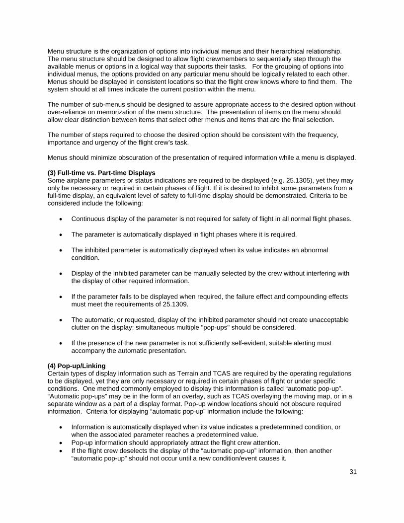
31
Menu structure is the organization of options into individual menus and their hierarchical relationship. The menu structure should be designed to allow flight crewmembers to sequentially step through the available menus or options in a logical way that supports their tasks. For the grouping of options into individual menus, the options provided on any particular menu should be logically related to each other. Menus should be displayed in consistent locations so that the flight crew knows where to find them. The system should at all times indicate the current position within the menu. The number of sub-menus should be designed to assure appropriate access to the desired option without over-reliance on memorization of the menu structure. The presentation of items on the menu should allow clear distinction between items that select other menus and items that are the final selection. The number of steps required to choose the desired option should be consistent with the frequency, importance and urgency of the flight crew’s task. Menus should minimize obscuration of the presentation of required information while a menu is displayed. (3) Full-time vs. Part-time Displays Some airplane parameters or status indications are required to be displayed (e.g. 25.1305), yet they may only be necessary or required in certain phases of flight. If it is desired to inhibit some parameters from a full-time display, an equivalent level of safety to full-time display should be demonstrated. Criteria to be considered include the following:
• Continuous display of the parameter is not required for safety of flight in all normal flight phases.
• The parameter is automatically displayed in flight phases where it is required.
• The inhibited parameter is automatically displayed when its value indicates an abnormal condition.
• Display of the inhibited parameter can be manually selected by the crew without interfering with
the display of other required information.
• If the parameter fails to be displayed when required, the failure effect and compounding effects must meet the requirements of 25.1309.
• The automatic, or requested, display of the inhibited parameter should not create unacceptable
clutter on the display; simultaneous multiple "pop-ups" should be considered.
• If the presence of the new parameter is not sufficiently self-evident, suitable alerting must accompany the automatic presentation.
(4) Pop-up/Linking Certain types of display information such as Terrain and TCAS are required by the operating regulations to be displayed, yet they are only necessary or required in certain phases of flight or under specific conditions. One method commonly employed to display this information is called “automatic pop-up”. “Automatic pop-ups” may be in the form of an overlay, such as TCAS overlaying the moving map, or in a separate window as a part of a display format. Pop-up window locations should not obscure required information. Criteria for displaying “automatic pop-up” information include the following:
• Information is automatically displayed when its value indicates a predetermined condition, or when the associated parameter reaches a predetermined value.
• Pop-up information should appropriately attract the flight crew attention. • If the flight crew deselects the display of the “automatic pop-up” information, then another
“automatic pop-up” should not occur until a new condition/event causes it.

32
• If an “automatic pop-up” condition is asserted and the system is in the wrong configuration or mode to display the information, and the system configuration can not be automatically changed, then an annunciation should be displayed in the color associated with the nature of the alert, prompting the flight crew to make the necessary changes for the display of the information.
• If a pop-up(s) occurs and obscures information, it should be shown that the obscured information is not relevant or necessary for the flight crew task. Additionally it should not cause a misleading presentation. Simultaneous multiple “pop-ups” should be considered.
• If more than one “automatic pop-up” occurs simultaneously on one display area, for example a Terrain and TCAS pop-up, then the system should prioritize the pop-up events based on their criticality.
• Any information to a given system that is not continuously displayed, but that the safety assessment of the system determines is necessary to be presented to the flight crew, should automatically pop-up or otherwise give an indication that its display is required.
8.4 Managing Display Configuration This section addresses the management of the information presented by an electronic display system and its response to failure conditions and flight crew selections. It will also provide guidance on the acceptability of display formats and their required physical location on the flight deck both during normal flight and in failure modes. Manual and automatic system reconfiguration and source switching are also addressed. (1) Managing Display Configuration in Normal Conditions In normal conditions (i.e. non failure conditions), there may be a number of possible display configurations that may be selected manually or automatically. All possible display configurations available to the flight crew should be designed and evaluated for arrangement, visibility, and interference. (2) Display System Reconfiguration This section provides guidance on manual and automatic display system reconfiguration in response to display system failure. The arrangement and visibility requirements also apply in failure conditions and alternative display locations used in non-normal conditions will have to be evaluated by the Authority. Moving display formats to different display locations on the flight deck or using redundant display paths to drive display information has been found to be acceptable to meet availability and integrity requirements. In an instrument panel configuration with a display unit for Primary Flight Information (PFI) positioned above a display unit for navigation information, it has been found acceptable to move the PFI to the lower display unit when the upper display unit has failed. In an instrument panel configuration with a display unit for Primary Flight Information (PFI) positioned next to a display unit for navigation information, it has been found acceptable to move the PFI to the display unit directly adjacent to it in case the preferred display unit has failed. It has been found acceptable to switch the navigation information to a centrally located auxiliary display (multifunction display). If several possibilities exist for relocating the failed display, there should be a recommended procedure in the airplane flight manual. It has been found acceptable to have manual or automatic switching capability in case of system failure (source, symbol generator, display unit) to ensure that required information remains available to the flight crew. In case several displays have failed, complete suppression of primary flight information may be considered for brief periods of time on a case-by-case basis, provided that the standby indication is operational and the primary flight information is readily recoverable.

33
The following means to reconfigure the displayed information have been found acceptable: • Display unit reconfiguration. Moving a display format to a different location (e.g. move the PFI to
adjacent display unit) or the use of a compacted format has been found acceptable.
• Source/graphic generator reconfiguration. The reconfiguration of graphic generator sources either manually or automatically to accommodate a failure has been found acceptable. In the case where both Captain and First Officer displays are driven by a single graphic generator source, there should be clear, cautionary alerting to the flight crew that the displayed information is from a single graphic generator source.
In certain flight phases, manual reconfiguration may not satisfy the need for the flying pilot to recover PFI without delay. Automatic reconfiguration might be necessary to cope with failure conditions that require immediate flight crew member action. When automatic reconfiguration occurs (e.g. display transfer), it should not adversely affect the performance of the flight crew and should not result in any trajectory deviation. When the display reconfiguration results in switching of sources or display paths that is not annunciated and is not obvious to the crew, care should be taken that the crew is aware of the actual status of the systems when necessary depending on flight deck philosophy. An alert should be given when the information presented to the crew is no longer meeting the required safety level, in particular single source or loss of independence.
8.5 Methods of Reconfiguration (1) Compacted Format The term "compacted format," as used in this AC, refers to a reversionary display mode where selected display components of a multi-display configuration are combined in a single display format to provide higher priority information. The “compacted format” may be automatically selected in case of a primary display failure or it may be manually selected by the flight crew. The concepts and requirements of § 25.1321, as discussed in Section 8.2.1, still apply. The compacted display format should maintain the same display attributes (color, symbol location, etc..) as the primary formats it replaces. The compacted format should ensure the proper operation of all the display functions it presents, including annunciation of navigation and guidance modes if present. Due to size constraints and to avoid clutter it may be necessary to reduce the amount of display functions on the compacted format. For example the use of numeric readouts in place of graphical scales has been found to be acceptable. Failure flags and mode annunciations should, wherever possible, be displayed in a location common with the normal format. (2) Sensor Selection and Annunciation Manual or automatic switching of sensor data to the display system is acceptable in the event of sensor failure. Independent attitude, direction, and air data sources are required for the Captain and First Officer displays of Primary Flight Information (Ref 14 CFR/CS25 § 25.1333). If sources can be switched such that the Captain and First Officer are provided with single sensor information, there should be a clear annunciation indicating this vulnerability to misleading information to both flight crew members. If sensor information sources can not be switched, then no annunciation is required.

34
There should be a means of determining the source of the displayed navigation information and the active navigation mode. If multiple or different type of navigation sources (FMS, ILS, GLS, etc.) can be selected (manually or automatically), then the selected source should be annunciated. For highly integrated display systems, automatic sensor switching is recommended to address those cases where multiple failure conditions may occur at the same time and require immediate flight crew member action. For automatic switching of sensors that is not annunciated and is not obvious to the crew, care should be taken that the crew is aware of the actual status of the systems when necessary. An alert should be given when the information presented to the crew is no longer meeting the required integrity level, in particular when there is a single sensor or loss of independence.

35
9 Display Control Devices Advances in technology have enabled displays to do more than just provide traditional information presentation. The means of interaction with the display system can be as varied as the modalities of human perception. Each of these modalities has characteristics unique to its operation that need to be considered in design of the functions it controls and the redundancy provided during failure modes. Despite the amount of redundancy that may be available to achieve a given task, the flight deck should still present a consistent user interface scheme for the primary displays and compatible, if not consistent, user interface scheme for auxiliary displays throughout the flight deck. (1) Multifunction controls should be labeled such that the pilot is able to:
• Rapidly, accurately, and consistently identify and select all functions of the control device • Quickly and reliably identify what item on the display is “active” as a result of cursor
positioning as well as what function will be performed if the item is selected using the selector buttons and/or changed using the multifunction knob.
• Determine quickly and accurately the function of the knob without extensive training or experience.
9.1 Mechanical Controls The installation guidelines below apply to control input devices that are dedicated to the operation of a specific function (e.g. control knobs, wheels), as well as new control features (e.g. Cursor Control Device, or CCD). Mechanical controls (e.g knobs, wheels) used to set numeric data on a display should have adequate friction or tactile detents to allow the flight crew to set values (e.g. setting an out-of-view heading bug to a displayed number) without extensive training or experience.. Controls for this purpose should have an appropriate amount of feel to minimize the potential for inadvertent changes. The display response gain to control input should be optimized for gross motion as well as fine positioning tasks without overshoots. The sense of motion of controls should comply with the requirements of §25.779, where applicable.
9.2 Software Controls Display systems can range from no crew interaction to crew interaction that can affect airplane systems. Three display types are identified below. i) Display only: The most common function of displays is to provide information only. This includes display technologies (e.g. CRT, LCD).There is no crew interaction involved other than perception of the display information. ii) Interactive display: Displays that utilize a graphical user interface (GUI) permit information within different display areas to be directly manipulated by the crew (e.g. changing range, scrolling CAS messages or electronic checklists, configuring windows, layering information). This level of display interaction affects only the presentation of display information and has a minimal effect on flight deck operations. There is no effect on control of airplane systems. iii) Airplane system control through displays: Displays that provide a GUI to control airplane systems operations (e.g., utility controls on displays traditionally found in overhead panel functions, FMS

36
operations, graphical flight planning) are also considered "interactive”. The amount of airplane control that a system provides should be compatible with, and equivalent testing required, for the level of criticality of the GUI and control device for that system. These are discussed in detail in section 9.1 below. The design of display systems as “controls” is dependent on the functions they control, and the applicant should consider the following guidelines: (1) Redundant methods of controlling the system may lessen the criticality required of the display control.
Particular attention should be paid to the interdependence of display controls (i.e. vulnerability to common mode failures), and to the combined effects of the loss of control of multiple systems and functions.
(2) The applicant should demonstrate that the failure of any display control does not unacceptably disrupt
operation of the airplane (i.e. the allocation of flight crew member tasks) in normal, non-normal and emergency conditions.
(3) To show compliance with §§ 25.777(a) and 25.1523, the applicant should show that the flight crew
can conveniently access required and backup control functions in all expected flight scenarios, without unacceptable disruption of airplane control, crew task performance, and Crew Resource Management (CRM).
(4) Control system latency and gains can be important in the acceptability of a display control. Usability
testing should therefore accurately replicate the latency and control gains that will be present in the actual airplane.
(5) To minimize flight crew workload and error, the initial response to a control input should take no
longer than250 msec to acknowledge the input. If the initial response to a control input is not the same as the final expected response, a means of indicating the status of the pilot input should be made available to the flight crew.
(6) To show compliance with § 25.771(e )the applicant should show by test and/or demonstration in
representative motion environment(s) (e.g. turbulence) that the display control is acceptable for controlling all functions that the flight crew may access during these conditions.
9.3 Cursor Control Device When the input device controls cursor activity on a display, it is called a cursor control device (CCD). CCDs are used to position display cursors on selectable areas of the displays. These selectable areas are “soft controls” intended to perform the same functions as mechanical switches or other controls on conventional control panels. Typically CCDs provide control of several functions and are the means for directly manipulating display elements. In addition to the above guidelines the following are design considerations unique to CCDs. (1) The CCD design and installation should enable the flight crew to clearly and precisely control the
CCD, and to maintain display configuration control, without exceptional skill during foreseeable flight conditions, both normal and adverse (e.g. turbulence, vibrations). Certain selection techniques, such as double or triple clicks, should be avoided..
(2) The safety assessment of the CCD may need to address reversion to alternate means of control
following loss of the CCD. This includes an assessment on the impact of the failure on crew workload. (3) The functionality of the CCD should be demonstrated with respect to the flight crew interface considerations outlined below:

37
(a) The ability of the flight crew to share tasks, following CCD failure, with appropriate workload and efficiency.
(b) The ability of the flight crew to use the CCD with accuracy and speed of selection, required of the related tasks, under foreseeable operating conditions (e.g. turbulence, engine imbalance. vibration).
(c) Satisfactory flight crew task performance and CCD functionality, whether the CCD is operated with a dominant or non-dominant hand.
(d) Hand stability support position (e.g. wrist rest). (e) Ease of recovery from incorrect use.
9.4 Cursor Display (1) The cursor display should be restricted from areas of primary flight information or where occlusion of
display information by a cursor could result in misinterpretation by the crew. If a cursor is allowed to enter a critical display information field, it should be demonstrated to not cause interference for all phases of flight and failure conditions that it will be presented in.
(2) Manipulation of the cursor on the display allows crew access to display elements. Because it is a
directly controllable element on the display it has unique characteristics that need consideration:
(a) Presentation of the cursor should be clear, unambiguous, and easily detectable in all foreseeable operating conditions.
(b) The failure mode of an uncontrollable and distracting display of the cursor should be evaluated.
(c) Because in most applications more than one crew member will be using the cursor, the applicant should establish an acceptable method for handling “dueling cursors” that is compatible with the overall flight deck philosophy (e.g., “last person on display wins”).
(d) If a cursor is allowed to fade from a display, some means should be employed for the crew to quickly locate it on the display system. Common examples of this are “blooming” or “growing” the cursor to attract the crew’s attention.
(e) A means should be provided to distinguish between cursors if more than one is used on a display system.

38
10 Compliance Considerations (Test and Compliance) This section provides considerations and guidance for demonstrating compliance to the regulations for the approval of electronic flight deck displays. Since some much of display system compliance is dependent on subjective evaluations by pilots and human factors specialist, this section will focus on providing specific guidance that facilitates these types of evaluations. The acceptable means of compliance (MOC) for a given display system may depend on many factors, and is determined on a case-by-case basis. For example, when the proposed display system is mature and well understood, less rigorous means such as analogical reasoning (i.e., documented as a Statement of Similarity) may be sufficient. However, more rigorous and structured methods (e.g., analysis and flight test) are appropriate if, for example, the proposed display system design is deemed novel, complex or highly integrated. In selecting the MOC, other factors might include the subjectivity of the acceptance criteria, and the evaluation facilities of the applicant (e.g., high-fidelity flight simulators). Furthermore, the manner in which these facilities are used (e.g., data collection) are influenced by the considerations listed below.
10.1 Means of Compliance (MOC) Descriptions The following MOC descriptions are focused on electronic displays:
A. System Descriptions. System descriptions may include a system architecture, description of the layout and general arrangement of the flight deck, description of the intended function, crew interfaces, system interfaces, functionality, operational modes, mode transitions, and characteristics (e.g. dynamics of the display system), and applicable requirements addressed by this description. Layout drawings and/or engineering drawings may show the geometric arrangement of hardware or display graphics. Drawings typically are used when demonstration of compliance can easily be reduced to simple geometry, arrangement, or the presence of a given feature, on a technical drawing. The following questions may be used to evaluate whether the description of intended function is sufficiently specific and detailed:
• Does each system, feature and function have a stated intended function?
• What assessments, decisions, or actions are the flight crewmembers intended to make based on the display system?
• What other information is assumed to be used in combination with the display system?
• What is the assumed operational environment in which the equipment will be used (e.g., the pilots tasks and operations within the flight deck, phase of flight and flight procedures)
B. Statement of similarity. This is a substantiation to demonstrate compliance by a comparison to a
previously approved display (system or function). The comparison details the physical, logical, and functional and operational similarities of the two systems. This method of compliance should be used with care because the flight deck should be evaluated as a whole, rather than merely as a set of individual functions or systems. For example, display functions that have been previously approved on different programs may be incompatible when applied to another flight deck. Also, changing one feature in a flight deck may necessitate corresponding changes in other features, in order to maintain consistency and prevent confusion.
C. Calculation & Engineering Analysis. These include assumptions of relevant parameters and
contexts, such as the operational environment, pilot population, and pilot training. For analyses that are not based on advisory material or accepted industry standards, validation of calculations

39
and engineering analysis using direct participant interaction with the display should be considered. Examples of analysis include computer modeling to show performance (e.g. optical performance) and human performance timing (e.g., latency, potential workload).
D. Evaluation. This is an assessment of the design, conducted by the applicant, who then provides
a report of the results to the Authority. Evaluations have two defining characteristics that distinguish themselves from tests: (1) the representation of the display design does not necessarily conform to the final documentation, and (2) the Authority does not need to be present. Evaluations may contribute to a finding of compliance, but they generally do not constitute a finding of compliance by themselves.
Evaluations may begin early in the program. They may involve static assessments of the basic design and layout of the display, part-task evaluations and/or, full task evaluations in an operationally representative environment (environment may be simulated). A wide variety of development tools may be used for evaluations, from mockups to full installation representations of the actual product or flight deck. In cases where human subjects (typically pilots) are used to gather data (subjective or objective), the applicant should fully document the process used to select subjects, the type of data collected, and the method(s) used to collect the data. This should be provided to the Authority in advance to get agreement on the extent to which the evaluations are valid and relevant for certification credit. Additionally, credit will depend on the extent to which the equipment and facilities actually represent the flight deck configuration and realism of the flight crew tasks.
E. Test. This MOC is conducted in a manner very similar to evaluations (see above), but is
performed on conformed systems (or conformed items relevant to the test), in accordance with an approved test plan, with either the aircraft certification authority or their designated representative present. A test can be conducted on a test bench, in a simulator, and/or on the actual aircraft, and is often more formal, structured and rigorous than an evaluation.
Bench or simulator tests that are conducted to show compliance should be performed in an environment that adequately represents the airplane environment, for the purpose of those tests. Flight tests can be the validation and verification of other data, such as display unusual attitude behavior from analysis, evaluations, and simulation. It is often best to use flight tests as a final confirmation of data collected using other means of compliance. “Workload assessments in the presence of failures and validation of failure effect classification need to be addressed in a simulator and/or the actual airplane during certification.”
11 Considerations for Continued Airworthiness and Maintenance This section provides guidance for the preparation of instructions for continued airworthiness of the display system and its components, to show compliance with 25.1309 and 25.1529 (including Appendix H) which requires that Instructions for Continued Airworthiness should be prepared. The guidance given is not a definitive list, and other maintenance tasks may be developed as a result of the safety assessment, design reviews, manufacturer’s recommendations, and Maintenance Steering Group (MSG)-3 analyses that are conducted.
11.1 General Considerations Information on the preparation of the instructions for continued airworthiness can be found in Appendix H to Part 25.

40
(i) If the display system uses pin programming by software means, maintenance information should be provided to enable replacement display equipment to be programmed with the approved airplane configuration. (ii) Maintenance procedures may also need to be considered for: (a)Reversionary switches if they are not used in normal operation. The concern is that they are potential latent failures, and consequently the switching or back up display/sensor may not be available when required. These failures may be addressed by a System Safety Assessment, and in the preparation of the airplane’s maintenance program (e.g. MSG-3). (b) Display cooling fans and filters integral with cooling ducting.
11.2 Design for Maintainability The system should be designed to minimize maintenance error:
(i)The display mounting, connectors, and labeling, should allow quick, easy, safe, and correct access, for identification, removal and replacement. Means should be provided (e.g. physically coded connectors) to prevent inappropriate connections of system elements (ii) If the system has the capability of providing information on system faults (e.g. diagnostics) to maintenance personnel, it should be displayed in text instead of coded information. (iii) If the flight crew needs to provide information to the maintenance personnel (example: Overheat warning), problems associated with the display system should be communicated to the flight crew as appropriate, relative to the task and criticality of the information displayed.
(iv) Suitable maintenance instructions should be provided with installation design changes. For example, this may include wiring diagram information addressing pin programming, following the incorporation of a Supplemental Type Certificate (STC) that introduces a new or modified interface to the display system.
11.3 Maintenance of Display Characteristics Maintenance procedures may be used to ensure that the display characteristics remain within the levels presented and accepted at certification. Experience has shown that display quality may degrade with time and become difficult to use. Examples are: lower brightness/contrast; distortion or discoloration of the screen (blooming effects); and parts of the screens that may not display information properly. Test methods and criteria may be established to determine if the display system remains within acceptable minimum levels. Display system manufacturers may alternatively provide “end of life“ specifications for the displays which could be adopted by the aircraft manufacturer.

41
12 Glossary of Acronyms/Abbreviations AC – Advisory Circular ADI- Attitude Director Indicator AFM-Airplane Flight Manual AMC-Acceptable Means of Compliance AMJ - Advisory Material Joint ARP-Aerospace Recommended Practices AS-Aerospace Standard CAS- Crew Alerting System CCD- Curser Control Device CDI- Course Deviation Indicator CFIT - controlled flight into terrain CFR – Code of Federal Regulations CIE- Commissions Internationale de L’Eclairage COM-Communication CRT – Cathode Ray Tube CS-Certification Specification (EASA Only) DAL - Development Assurance Level DEP- Design Eye Position DME-Distance Measuring Equipment DOD-Department of Defense DU- Display Unit EADI-Electronic Attitude Direction Indicator EASA- European Aviation Safety Agency EDS - Electronic Display System EFB – Electronic Flight Bag EGT- Exhaust Gas Temperature EHSI-Electronic Horizontal Situation Indicator EICAS –Engine Indicating and Crew Alerting System ETSO-European Technical Standard Order EURCAE – European Organization for Civil Aviation Equipment EVS-Enhanced Vision System FAA – Federal Aviation Administration FADEC - Full Authority Digital Engine Controls FHA- Functional Hazard Assessment FMS-Flight Management System FOV-Field of View GLS – GNSS (Global Navigation Satellite System) Landing System GPS – Global Positioning System GUI-Graphical User Interface HDD- Head down Display HUD –Head up Display ICAO-International Civil Aviation Organization IFE - In Flight Entertainment ILS-Instrument Landing System INS- Inertial Navigation System I/O- Input/Output ISD-Integrated Standby Display JAA- Joint Airworthiness Authority LCD –Liquid Crystal Display LED-Light Emitting Diode MASPS- Minimum Aviation System Performance Standard

42
MFD- Mutli-Function Display MIL STD- Military Standard MMO- Maximum Operating Mach Number MOC - Means Of Compliance MOPS- Minimum Operational Performance Standard MSG - Maintenance Steering Group ND-Navigation Display PFD-Primary Flight Display PFI-Primary Flight Information PI-Powerplant Information SA-Situation Awareness SAE- Society of Automotive Engineers STC - Supplemental Type Certificate SVS-Synthetic Vision System TAWS-Terrain Awareness and Warning System TCAS-Traffic Alert and Collision Avoidance System TSO-Technical Standard Order UA - User Application VHF-Very High Frequency VMO- Maximum Operation Speed VOR- Very High Frequency Omnirange

43
13 Definitions Basic T – The arrangement of primary flight information as required by 25.1321(b); including attitude, airspeed, altitude, and direction information. Brightness: The perceived or subjective luminance. As such, it should not be confused with luminance. Chrominance – The quality of a display image which includes both luminance and chromaticity and is a perceptual construct subjectively assessed by the human observer. Chromaticity: Color characteristic of a symbol or an image defined by its u’, v’ coordinates (CIE pub number 15.2, Colorimetry, second edition 1986). Coding characteristics: Coding characteristics are readily identifiable attributes commonly associated with a symbol by means of which such symbols are differentiated; i.e., size, shape, color, motion, location, etc. Color coding – A means to use color to differentiate display information. Command information: Displayed information directing a control action. Compact mode – In display use, this most frequently refers to a single, condensed display presented in numeric format that is used during reversionary or failure conditions. Conformal: Refers to displayed information which overlays the real world element that it is meant to portray irrespective of the viewing position. Contrast Ratio: For HUD – ratio of the luminance over the background scene (AS 8055) For HDD – ratio of the total foreground luminance to the total background luminance Criticality: Indication of the hazard level associated with a function, hardware, software, etc., considering abnormal behavior (of this function, hardware, software) alone, in combination, or in combination with external events. Design eye position: The position at each pilot's station from which a seated pilot achieves the optimum combination of outside visibility and instrument scan. The design eye position is a single point selected by the applicant that meets the requirements of Secs. 25.773(d) and 25.777(c) for each pilot station. It is normally a point fixed in relation to the aircraft structure (neutral seat reference point) at which the midpoint of the pilot’s eyes should be located when seated at the normal position. The DEP is the principal dimensional reference point for the location of flight deck panels, controls, displays, and external vision. Display refresh rate: The rate at which a display completely refreshes its image Display response time: time needed to change the information from one level of luminance to a different level of luminance. Display response time related to the intrinsic response (time linked to the electro-optic effect used for the display and the way to address it). Display Surface/Screen: The area of the display unit that provides an image. Display System: The entire set of avionic devices implemented to display information to the flight crew. Also known as an Electronic Display System (EDS)

44
Display Unit: A line replaceable unit that is located in the flight deck, in direct view of the flight crew, that is used to provide display information. Examples include a color head down display, and a head up display projector and combiner. Enhanced Vision System (EVS): An electronic means to provide a display of the forward external scene topography (natural or manmade features of a place or region especially in a way to show their relative positions and elevation) through the use of imaging sensors, such as a forward looking infrared, millimeter wave radiometry, millimeter wave radar, low light level image intensifying. Note: An Enhanced Flight Vision System (EFVS) is an EVS that is intended to be used for instrument approaches under provisions of 14 CFR §91.175 (l) and (m), and must display the imagery with instrument flight information on a head up display. Eye Reference Position: A single spatial position located at or near the center of the HUD Eye Box. The HUD ERP is the primary geometrical reference point for the HUD. Failure: An occurrence which affects the operation of a component, part, or element, such that it can no longer function as intended (this includes both loss of function and malfunction). Note: errors may cause failures but are not considered to be failures. Failure Condition: A condition having an effect on the airplane and/or its occupants, either direct or consequential, which is caused or contributed to by one or more failures or errors, considering flight phase and relevant adverse operational or environmental conditions, or external events. Field of View: The angular extent of the display that can be seen by either pilot with the pilot seated at the pilot’s station. Flicker – An undesirable display effect that occurs when a display does not generate quickly enough and can cause discomfort for the viewer (such as headaches and irritation). Flight Deck Philosophy – A high level description of the design principles that guide the designer and ensure a consistent and coherent interface is presented to the flight crew. Functional Hazard Assessment: A systematic, comprehensive examination of airplane and system function to identify potential Minor, Major, Hazardous, and Catastrophic failure conditions that may arise as a result of a malfunction or a failure to function. Format (Fig 13-2): An image rendered on the whole display unit surface. A format is constructed from one or more windows (Ref ARINC661) Gray Scale: number of incremental luminance levels between full dark and full bright Hazard: Any condition that compromises the overall safety of the airplane or that significantly reduces the ability of the flight crew to cope with adverse operating conditions. HUD Design eye box: The three-dimensional area surrounding the design eye position, which defines the area, from which the HUD symbology performance parameters are defined. Icon – A single graphical symbol that represents a function or event. Image Size: useful viewing area (field) of the display surface. • Direct view display: it refers to the useful (or active) area of the display (ex: units cm x cm) • Head Up Display: the Total Field Of View (units usually in degrees x degrees)

45
(Total field of view defines the maximum angular extent of the display that can be seen by either eye allowing head motion within the eyebox. (AS8055)) Indication: Any visual information - e.g. graphical gauges, graphical representations, numeric data displays (i.e. numeric), messages, lights, symbols, synoptics, etc. Information update rate: The rate at which new data is displayed or updated. Interaction – the ability to directly affect a display by utilizing a graphical user interface (GUI) that consists of a control device (e.g, trackball), cursor, and “soft” display control that is the cursor target. Latency: The time taken by the display system to react to a triggered event coming from I/O device, the symbol generator, the graphic processor, or the information source). Layer (Fig 13-3): A layer is the highest level entity of the Display System that is known by a User Application (UA). Luminance: Visible light that is emitted from the display. Commonly-used units: foot-lamberts, cd/m2 Menu: A displayed list of items from which the flight crewmember can choose Mirror image – the arrangement of a pair of displays or control panels where the images or controls are laid out such that they are flipped representations of each other. Misleading Information: Misleading information is incorrect information that is not detected by the flight crew because it appears as correct and credible information under the given circumstances. When incorrect information is automatically detected by a monitor resulting in an indication to the flight crew or when the information is obviously incorrect, it is no longer considered misleading. The consequence of misleading information will depend on the nature of the information, and the given circumstances. Mode: A mode is the functional state of a display and/or control system(s). A mode can be manually or automatically selected. Occlusion: Visual blocking of one symbol by another. Sometimes called sparing or occulting. Partitioning – A technique for providing isolation between functionality independent software components to contain and/or isolate faults and potentially reduce the effort of the software verification process. Pixel: LCD picture element which usually consists of three (red, green, blue) sub-pixels (also called dots on a CRT). Primary Displays – The display used to present primary flight information. Primary Field of View (FOV) – Primary Field-of-View is based upon the optimum vertical and horizontal visual fields from the design eye reference point that can be accommodated with eye rotation only. The description below provides an example of how this may apply to head-down displays. Primary flight information – The information whose presentation is required by 25.1303(b) and 25.1333(b), and arranged by 25.1321(b).

46
Primary flight instrument - A primary flight instrument is any display or instrument that serves as the flight crew’s primary reference of a specific parameter of primary flight information. For example, a centrally located attitude director indicator (ADI) is a primary flight instrument because it is the flight crew’s primary reference for pitch, bank, and command steering information. Primary flight reference (PFR): A primary flight reference is any display, or suite of displays or instruments, that provides the flight crew with primary flight information. Resolution: Size of the minimum element that can be displayed, expressed by the total number of pixels or dots. Pixel Defect: A pixel that appears to be in a permanently on or off-state. Required Powerplant Parameters – The information whose presentation is required by 25.1305. Reversionary – This event occurs refers to the crew initiated (manual) or automatic relocation of displays following a display failure. Shading - Shading is a variation on chromatic coordinates along an axis. Shading is used as: • a coding method for separating information, change in state, give emphasis, and depth information • a blending method between graphic elements (map displays, SVS) • to enhance similarity between a synthetic image and the real world image Software control – display elements used to manipulate, select, or de-select information (e.g. menus and soft keys) Standby Display – A backup display that is used in case of a primary display malfunction. Status information: Information about the current condition of an airplane system and its surroundings. Symbol: A symbol is a geometric form or alphanumeric information used to represent the state of a parameter on a display. The symbol maybe further defined by its location and motion on a display. Synthetic Vision System: A system which creates computer generated imagery or symbology representing how an outside forward vision scene would otherwise appear, or elements of that scene would appear, if a pilot could optically see through the visibility restriction or darkness. Texturing - Texturing is a graphic, pictorial effect placed on a display surface to give the surface a specific “look” (metallic, grassy, cloudy, etc.). Texturing is used as: • a coding method for separating information, change in state, give emphasis, and depth information • a blending method between graphic elements (map displays, SVS) • to enhance similarity between a synthetic image and the real world image Transparency – Transparency is a way of allowing seeing “through” a front element what’s “behind”. By doing this, it can alter the color perception of both the “front” and “back” element. User Application: A user application is an avionics system, interfaced with the display system, which uses the display system as a resource to display and collect information related to its own function (Ref. A661). User Application Layer Definition or Definition file: The layer definition or definition file is a software file, running on the display system but defined by the user application which describes the constitution of images (widgets hierarchical structure) as needed by the User Application (Ref. ARINC661).

47
Viewing Envelope (Fig 13-1): total volume of space where the minimum optical performance of the display is met (e.g. luminance, contrast, chromaticity.). For a direct view display it is the solid angle with respect to the normal of the display image and for a HUD a three- dimensional volume (Eyebox). Widget (Fig 13-3): A single graphical object. A widget is a generic object whose parameters can be set dynamically by a User Application. Window (Fig 13-2, 13-3): A rectangular physical area of the display surface. A window consists of one or more layers (Ref. ARINC661). Windowing – The technique to create windows. Segmenting a single display area into two or more independent display areas or inserting a new display area onto an existing display.
Figure 13-1 – Viewing Envelope
Image
EyeboxViewing angle
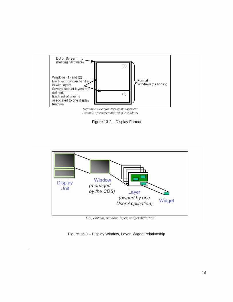
48
Figure 13-2 – Display Format
Figure 13-3 – Display Window, Layer, Wigdet relationship .

49

50
14 Related Regulations and Documents
14.1 General The regulations and standards listed below are applicable to particular systems or functions which may have implications on the display system characteristics even though they do not explicitly state display requirements. It is not an exhaustive list, and the references should be reviewed to ensure currency of issue status, and to check for any others that may be applicable.
14.2 Regulatory Sections The following is a complete list of regulations/certifications that should be considered when certifying a display system:
§ 25.143 Controllability and Maneuverability: General § 25.207 Stall warning § 25.672 Stability augmentation and power operated systems § 25.677 Trim systems § 25.679 Control system gust locks § 25.699 Lift and drag device indicator § 25.703 Takeoff warning system § 25.729 Retracting mechanism § 25.771 Pilot compartment § 25.773 Pilot compartment view § 25.777 Cockpit controls § 25.783 Doors § 25.812 Emergency lighting § 25.841 Pressurized cabins § 25.854 Lavatory fire protection § 25.857 Cargo compartment classification § 25.858 Cargo or baggage compartment smoke or fire detection systems § 25.859 Combustion heater fire protection § 25.863 Flammable fluid fire protection § 25.901 Powerplant installation § 25.903 Engines § 25.904 Automatic takeoff thrust control system (ATTCS) § 25.1001 Fuel Jettison Systems § 25.1019 Oil strainer or filter § 25.1141 Powerplant controls: General § 25.1165 Engine ignition systems § 25.1199 Extinguishing agent containers § 25.1203 Fire detector system § 25.1301 Function and installation § 25.1303 Flight and navigation instruments § 25.1305 Powerplant instruments § 25.1309 Equipment, systems, and installations § 25.1316 System lightning protection § 25.1321 Arrangement and visibility § 25.1322 Warning, caution, and advisory lights § 25.1323 Airspeed indicating system

51
§ 25.1326 Pitot heat indication systems § 25.1327 Magnetic direction indicator § 25.1329 Automatic pilot system § 25.1331 Instruments using a power supply § 25.1333 Instrument systems § 25.1335 Flight director systems § 25.1337 Powerplant instruments § 25.1351 Electrical Systems and Equipment: General § 25.1353 Electrical equipment and installations § 25.1355 Distribution system § 25.1357 Circuit protective devices § 25.1381 Instrument lights § 25.1383 Landing lights § 25.1419 Ice protection § 25.1431 Electronic equipment § 25.1435 Hydraulic systems § 25.1441 Oxygen equipment and supply § 25.1457 Cockpit voice recorders § 25.1459 Flight recorders § 25.1501 Operating Limitations and Information: General § 25.1523 Minimum flight crew § 25.1529 Instructions for Continued Airworthiness § 25.1541 Markings and Placards: General § 25.1543 Instrument markings: General § 25.1545 Airspeed limitation information § 25.1547 Magnetic direction indicator § 25.1549 Powerplant and auxiliary power unit instruments § 25.1551 Oil quantity indication § 25.1553 Fuel quantity indicator § 25.1555 Control markings § 25.1563 Airspeed placard § 25.1581 Airplane Flight Manual :General § 25.1583 Operating limitations § 25.1585 Operating procedures § 33.71 Lubrication System § 91.33 Instrument and equipment requirements § 91.205 Powered civil aircraft with standard category U.S. airworthiness certificates: Instrument and equipment requirements § 91.219 Altitude alerting system or device; turbojet powered civil airplanes § 91.221 Traffic Alert and Collision Avoidance System Equipment and use § 91.223 Terrain Awareness and Warning System CFR 91 Appendix A, Section 2 Required Instruments and Equipment § 121.221 Fire Precautions § 121.305 Flight and navigational equipment § 121.307 Engine Instruments § 121.308 Lavatory Fire Protection § 121.313 Miscellaneous Equipment § 121.323 Instruments and Equipment for Operations at Night § 121.325 Instruments and Equipment for Operations under IFR or Over-the-Top § 121.344 Digital Flight Data Recorders for Transport Category Aeroplanes (note : DFDRs may be required to record Electronic display status) § 121.354 Terrain awareness and warning system § 121.356 Traffic Alert and Collision Avoidance System § 121.357 Airborne Weather Radar Equipment Requirements § 121.358 Low-Altitude Windshear Systems Requirements

52
§ 121.360 Ground proximity warning – glideslope deviation alerting system § 135.149 Equipment requirements: General § 135.153 Ground Proximity Warning System § 135.154 Terrain Awareness and Warning System § 135.159 Equipment requirements: Carrying passengers under Visual Flight Rules (VFR) at night or under VFR over-the-top conditions § 135.163 Equipment requirements: Aircraft carrying passengers under Instrument Flight Rules (IFR) § 135.180 Traffic Alert and Collision Alerting System CFR 135 Appendix A, Additional Airworthiness Standards for Ten or More Passenger Airplanes
14.3 Advisory Circulars and Related Documents (1) FAA Documents Note: The ACs, Orders and policy memorandum can be accessed on the FAA website: www.faa.gov. Copies of current editions of the following publications may be obtained free of charge from the U.S. Department of Transportation, Subsequent Distribution Office, M-30, Ardmore East Business Center, 3341 Q 75th Avenue, Landover, MD 20785. AC20-88A Guidelines on the Marking of Aircraft Powerplant Instruments (Displays) AC 20-115B Radio Technical Commission for Aeronautic, Inc. Document RTCA/DO-178B AC20-129 Airworthiness Approval of Vertical Navigation (VNAV) Systems for use in the
National Airspace System (NAS) and Alaska AC20-130A Airworthiness approval of Navigation or Flight Management Systems
Integrating Multiple Navigation Sensors AC20-131A Airworthiness approval of Traffic Alert and Collision Avoidance Systems (TCAS
II) and mode S transponders AC 20-136 Protection of Aircraft Electrical/Electronic Systems against the Indirect Effects
of Lightning AC20-138A Airworthiness approval of Global Navigation Satellite Systems (GNSS)
Equipment AC20-140 Guideline for Design Approval of Aircraft Data Communications Systems AC 20-145 Guidance For Integrated Modular Avionics (IMA) that Implement TSO-C153
Authorized Hardware Elements AC20-151 Airworthiness Approval of Traffic Alert and Collision Avoidance Systems (TCAS
II) Version 7.0 and Associated Mode S Transponders AC20-152 RTCA, Inc., Document RTCA/DO-254, Design Assurance Guidance for
Airborne Electronic Hardware AC20-155 SAE Documents to Support Aircraft Lightning Protection Certification

53
AC 25-4 Inertial Navigation System (INS) AC 25-7A Flight Test Guide for Certification of Transport Category Airplanes AC 25-12 Airworthiness Criteria for the Approval of Airborne Windshear Warning
Systems in Transport Category AC25-15 Approval of Flight Management Systems in Transport Category Airplanes AC 25-23 Airworthiness Criteria for the Installation Approval of aTerrain Awareness and
Warning System (TAWS) for Part 25 Airplanes AC 25-24 Sustained Engine Imbalance AC 25-703-1 Takeoff Configuration warning Systems AC 25.1309-1A System Design and Analysis AC25.1329-1A Automatic Pilot Systems Approval AC 90-45A Approval of Area Navigation Systems for use in the US National Airspace
System AC120-28D Criteria for Approval of Category III Weather Minima for Takeoff, Landing, and
Rollout AC120-29A Criteria for Approval of Category I and Category II Weather Minima for
Approach. AC120-41 Criteria for Operational Approval of Airborne Wind Shear Alerting and Flight
Guidance AC120-55B Air Carrier Operational Approval and Use of TCAS II AC120-64 Operational Use and Modification of Electronic Checklists AC 120-76A Guidelines for the Certification, Airworthiness, and Operational Approval of
Electronic Flight Bag Computing Devices Order 8110.49 Software Approval Guidelines, dated June 3, 2003 PS-ACE100-2001-004 Guidance for Reviewing Certification Plans to Address Human Factors for
Certification of Part 25 Small Airplanes
DOT/FAA/CT-03/05 Human Factors Design Standards for Acquisition of Commercial Off-The-Shelf
Subsystems, Non-Developmental Items, and Developmental Systems. This document can be accessed on the FAA website: www.hf.faa.gov.
DOT/FAA/OAM-TM-03-01 Multi-Function Displays A Guide for Human Factors Evaluations ICAO 8400/5 Procedures for Air Navigation Services, ICAO Abbreviations and Codes. Fifth
Edition-1999.
(2) JAA/EASA Documents

54
Note: Copies of the EASA documents can be obtained from the EASA website www.EASA.eu.int/agency measures. JAA documents have to be purchased separately.
AMC 20-4 Airworthiness Approval and Operational Criteria for the use of Navigation
Systems in European Airspace Designated for Basic RNAV Operations. AMC 20-5 Airworthiness Approval and Operational Criteria for the use of the Navstar
Global Positioning System (GPS). JAA TGL 8, Revision 2 Certification Considerations for the Airborne Collision Avoidance System :
ACAS II. JAA TGL 10, Rev. 1 Airworthiness and operational approval for precision RNAV operations in
designated European airspace JAA TGL 12 Certification Considerations for the Terrain Awareness and Warning System
:TAWS. CS AWO All Weather Operations (3) Technical Standard Orders (TSO) Note : You may obtain a copy of the current edition of the following publications from the Federal Aviation Administration; Aircraft Certification Service; Aircraft Engineering Division; Technical and Administrative Support Staff Branch, AIR-103; 800 Independence Avenue, SW; Washington, DC 20591 or at the FAA website: www.faa.gov. The following is a partial list of the FAA Technical Standard Orders (TSOs) that may relate to electronic displays. For a complete list of TSOs, see AC 20-110, “Index of Aviation Technical Standards Orders.” It should be noted applicants might apply for a TSO that does not adequately address all of the functionality in the system. Alternatively, applicants may apply for multiple TSOs, since no single TSO applies to all functions.
PARTIAL INDEX OF TSOs THAT MAY BE APPLICABLE
TSO-C2d Airspeed Instruments
TSO-C3d Turn and Slip Instrument
TSO-C4c Bank and Pitch Instruments
TSO-C5e Direction Instrument, Non-magnetic (Gyroscopically Stabilized)
TSO-C6d Direction Instrument, Magnetic (Gyroscopically Stabilized)
TSO-C7d Direction Instrument, Magnetic Non-Stabilized Type (Magnetic Compass)
TSO-C8d Vertical Velocity Instruments (Rate-of-Climb)
TSO-C9c Automatic Pilots
TSO-C10b Altimeter, Pressure Actuated, Sensitive Type

55
TSO-C31d High Frequency (HF) Radio Communications Transmitting Equipment Operating within the Radio Frequency Range of 1.5-30 Megahertz
TSO-C34e ILS Glide Slope Receiving Equipment Operating within the Radio Frequency Range of 328.6-335.4 Megahertz (MHz)
TSO-C35d Airborne Radio Marker Receiving Equipment
TSO-C36e Airborne ILS Localizer Receiving Equipment Operating within the Radio Frequency Range of 108-112 Megahertz (MHz)
TSO-C37d VHF Radio Communications Transmitting Equipment Operating within the Radio Frequency Range 117.975 to 137.000 Megahertz
TSO-C38d VHF Radio Communications Receiving Equipment Operating within the Radio Frequency Range 117.975 to 137.000 Megahertz
TSO-C40c VOR Receiving Equipment Operating within the Radio Frequency Range of 108-117.95 Megahertz (MHz)
TSO-C41d Airborne Automatic Direction Finding (ADF) Equipment
TSO-C43c Temperature Instruments
TSO-C44b Fuel Flowmeters
TSO-C46a Maximum Allowable Airspeed Indicator Systems
TSO-C47 Pressure Instruments – Fuel, Oil, and Hydraulic
TSO-C49b Electric Tachometer: Magnetic Drag (Indicator and Generator).
TSO-C52b Flight Director Equipment
TSO-C54 Stall Warning Instruments
TSO-C55 Fuel and Oil Quantity Instruments (Reciprocating Engine Aircraft)
TSO-C63c Airborne Weather and Ground Mapping Pulsed Radars
TSO-C66c Distance Measuring Equipment (DME) Operating within the Radio Frequency Range of 960-1215 Megahertz
TSO-C67 Airborne Radar Altimeter Equipment (For Air Carrier Aircraft)
TSO-C87 Airborne Low-Range Radio Altimeter
TSO-C92c Airborne Ground Proximity Warning Equipment

56
TSO-C93 Airborne Interim Standard Microwave Landing System Converter Equipment
TSO-C94a Omega Receiving Equipment Operating within the Radio Frequency Range of 10.2 to 13.6 Kilohertz
TSO-C95 Mach Meters
TSO-C101 Over Speed Warning Instruments
TSO-C104 Microwave Landing System (MLS) Airborne Receiving Equipment
TSO-C105 Optional Display Equipment for Weather and Ground Mapping Radar Indicators
TSO-C106 Air Data Computer
TSO-C110a Airborne Passive Thunderstorm Detection Equipment
TSO-C113 Airborne Multipurpose Electronic Displays
TSO-C115b Airborne Area Navigation Equipment Using Multi-Sensor Inputs
TSO-C117a Airborne Windshear Warning and Escape Guidance Systems for Transport Airplanes
TSO-C118 Traffic Alert and Collision Avoidance System (TCAS) Airborne Equipment, TCAS I
TSO-C119b Traffic Alert and Collision Avoidance System (TCAS) Airborne Equipment, TCAS II
TSO-C120 Airborne Area Navigation Equipment Using Omega/Very Low Frequency (VLF) Inputs
TSO-C129a Airborne Supplemental Navigation Equipment Using Global Positioning System (GPS)
TSO-C145a Airborne Navigation Sensors using the Global Positioning System (GPS) Augmented by the Wide Area Augmentation System (WAAS)
TSO-C146a Stand-Alone Airborne Navigation Equipment Using the Global Positioning System (GPS) Augmented By the Wide Area Augmentation System (WAAS)
TSO-C147 Traffic Advisory System (TAS) Airborne Equipment
TSO-C151b Terrain Awareness and Warning System
TSO-C153 Integrated Modular Avionics Hardware Elements

57
TSO-C165 Electronic Map Display Equipment for Graphical Depiction of Aircraft Position
14.4 Industry Documents Copies of current editions of the following publications may be obtained as follows and may be suitable resource material for additional information, guidance, and standards for electronic flight deck display systems. (1) ICAO Documents International Civil Aviation Organization 8400/5. Procedures for Air Navigation Services ICAO Abbreviations and Codes. Fifth Edition- 1999.6.3.4.1 (2) RTCA Documents Note: The RTCA documents are available from RTCA, Inc., Suite 805, 1828 L Street NW, Washington, DC 20036-4001 or at their website at www.rtca.org. The list of RTCA documents does not include those MOPS documents referenced in the aforementioned TSOs. DO-160( ) Environmental Conditions and Test Procedures for Airborne Equipment DO-178( ) Software Considerations in Airborne Systems and Equipment Certification DO-236( ) Minimum Aviation System Performance Standards: Required Navigation
Performance for Area Navigation DO-239 Minimum Operational Performance Standards for Traffic Information Service
(TIS) Data Link Communications DO-243 Guidance for Initial Implementation of Cockpit Display of Traffic Information DO-253A Minimum Operational Performance Standards for GPS Local Area
Augmentation System Airborne Equipment DO-254 Design Assurance Guidance for Airborne Electronic Hardware
DO-255 Requirements Specification for Avionics Computer Resource (ACR) DO-257A Minimum Operational Performance Standards for the Depiction of Navigation
Information on Electronic Maps DO-259 Applications Descriptions for Initial Cockpit Display of Traffic Information
(CDTI) Applications DO-268 Concept of Operations, Night Vision Imaging System for Civil Operators DO-275 Minimum Operational Performance Standards for Integrated Night Vision
Imaging System Equipment

58
DO-282A Minimum Operational Performance Standards (MOPS) for Universal Access Tranceiver (UAT) Automatic Dependent Surveillance - Broadcast
DO-283A Minimum Operational Performance Standards for Required Navigation
Performance for Area Navigation D0-286 Minimum Aviation System Performance Standards
(MASPS) for Traffic Information Service – Broadcast (TIS-B).
DO-289 Minimum Aviation System Performance Standards (MASPS) for Aircraft Surveillance Applications. D0-296 Safety Requirements for Aeronautical Operational Control (AOC) Datalink Messages. (3) EUROCAE documents Note: The EUROCAE documents are available from EUROCAE, 102 rue Etienne Dolet 92240, Malakoff, France or at their website at www.eurocae.org. The list of EUROCAE documents does not include those MOPS documents referenced in the aforementioned ETSO’s. ED-12( ) Software Considerations in Airborne Systems and Equipment Certification ED-14( ) Environmental Conditions and Test Procedures for Airborne Equipment ED-55 MOPS for Flight Data Recorder Systems ED-75( ) -1 MASPS Required Navigation Performance for Area Navigation ED-79 Certification Considerations for Highly Integrated or Complex Aircraft Systems ED-80 Design Assurance Guidance for Airborne Electronic Hardware ED-81 Certification of Aircraft Electrical/Electronic Systems for the Indirect Effects of Lightning ED-84 Aircraft Lightning Environment and Related Test Waveform Standard ED-90A Radio Frequency Susceptibility Test procedures ED-91 Aircraft Lightning Zoning Standard ED-96 Requirements Specification for an Avionics Computer Resource (See Kirk) ED-98 User Requirements for Terrain and Obstacle Data ED-107 Guide for Certification of Aircraft in a High Intensity Radiated Field (HIRF) Environment ED-112 MOPS for Crash Protected Airborne Recorder Systems (4) Society of Automotive Engineers

59
Note: The Society of Automotive Engineers (SAE International) documents are available from SAE, 400 Commonwealth Drive, Warrendale, PA 15096-0001 or from their website at www.sae.org. AS 425C Nomenclature and Abbreviations, Flight Deck Area ARP426A Compass System Installations AS 439A Stall Warning Instrument (Turbine Powered Subsonic Aircraft) ARP 571C Flight Deck Controls and Displays for Communication and Navigation Equipment for Transport Aircraft AIR818D Aircraft Instrument and Instrument System Standards: Wording, Terminology, Phraseology, and Environmental and Design Standards For ARP 926B Fault/Failure Analysis Procedure
AIR 1093A Numeral, Letter and Symbol Dimensions for Aircraft Instrument Displays ARP 1161A Crew Station Lighting—Commercial Aircraft ARP 1782A Photometric and Colorimetric Measurement Procedures for Airborne Direct View CRT Displays ARP 1834A Fault/Failure Analysis for Digital Systems and Equipment ARP 1874 Design Objectives for CRT Displays for Part 25 (Transport) Aircraft ARP 4032A Human Engineering Considerations in the Application of Color to Electronic Aircraft Displays ARP 4033 Pilot System Integration ARP 4101 Flight Deck Layout and Facilities ARP 4102 Flight Deck Panels, Controls, and Displays ARP 4102/7 Electronic Displays ARP4102/8 Flight Deck Head-Up Displays ARP4102/15 Electronic Data Management System (EDMS) ARP 4103 Flight Deck Lighting for Commercial Transport Aircraft ARP 4105B Abbreviations and Acronyms for Use on the Flight Deck ARP 4256A Design Objectives for Liquid Crystal Displays for Part 25 (Transport) Aircraft ARP 4260 Photometric and Colorimetric Measurement Procedures for Airborne Flat Panel Displays
ARP 4754 Certification Considerations for Highly Integrated or Complex Aircraft Systems

60
ARP 4761 Guidelines and Methods for Conducting the Safety Assessment Process on Civil Airborne Systems and Equipment ARP 5287 Optical Measurement Procedures for Airborne Head-Up Display (HUD) ARP 5288 Transport Category Airplane Head Up Display (HUD) Systems ARP 5289 Electronic Aeronautical Symbols ARP 5364 Human Factor Considerations in the Design of Multifunction Display Systems for Civil Aircraft
ARP 5365 Human Interface Criteria for Cockpit Display of Traffic Information ARP5413 Certification of Aircraft Electrical/Electronic Systems for the Indirect Effects of Lightning ARP5414 Aircraft Lightning Zoning ARP5415A Users Manual for Certification of Aircraft Electrical/Electronic Systems for the Indirect Effects of Lighting AS 8034 Minimum Performance Standard for Airborne Multipurpose Electronic Displays AS 8055 Minimum Performance Standard for Airborne Head Up Display (HUD) ARD 50017 Aeronautical Charting (NOTE: Unable to locate in SAE database) ARD 50062 Human Factors Issues Associated With Terrain Separation Assurance Display Technology (NOTE: Unable to locate in SAE database) NOTE: In the event of conflicting information, this AC takes precedence as guidance for certification of transport category airplane installations. (5) ARINC Documents ARINC 661 – Cockpit Display System Interfaces to User Systems (6) Other Documents Commissions Internationale de L’Eclairage (CIE) pub number 15.2, Colorimetry, second edition 1986).

61
Appendix A: Primary Flight Information (PFI) This section provides additional guidance on the display of primary flight information elements, which is the information whose presentation is required by 25.1303(b), 1333(b) and arranged by 1321(b). A.1 Attitude Pitch attitude display scaling should be such that during normal maneuvers (such as takeoff at high thrust-to-weight ratios) the horizon remains visible in the display with at least 5 degrees pitch margin available. An accurate, easy, quick-glance interpretation of attitude should be possible for all unusual attitude situations. Information to perform effective manual recovery from unusual attitudes using chevrons, sky pointers, and/or permanent ground-sky horizon on all attitude indications is recommended. Both fixed airplane reference and fixed earth reference bank pointers ("sky" pointers) have been found to be acceptable as a reference point for primary attitude information. A mix of these types in the same flight deck is not recommended. There should be a means to determine the margin to stall and display it when necessary. For example, a pitch limit indication has been found to be acceptable. There should be a means to identify an excessive bank angle condition prior to stall buffet. Sideslip should be clearly indicated to the flight crew (e.g. split trapezoid on attitude indicator), and an indication of excessive sideslip should be provided. A.1.2 Continued function of primary flight information (including standby) in conditions of unusual attitudes or in rapid maneuvers Primary flight information must continue to be displayed in conditions of unusual attitudes or in rapid maneuvers (25.1303). The pilot must also be able to rely on primary or standby instrument information for recovery in all attitudes and at the highest pitch, roll and yaw rates that may be encountered (25.1333). In showing compliance with the requirements of 14 CFR §§ 25.1301(d) and 25.1309(a), (b), (c) and (d), the analysis and test program must consider the following conditions that might occur due to pilot action, system failures or external events:
abnormal attitude (including the airplane becoming inverted); excursion of any other flight parameter outside protected flight boundaries; or flight conditions that may result in higher than normal pitch, roll or yaw rates.
For each of the conditions identified above, primary flight displays and standby indicators must continue to provide useable attitude, altitude, airspeed and heading information and any other information that the pilot may require to execute recovery from the unusual attitude and/or arrest the higher than normal pitch, roll or yaw rates. A.2 Airspeed and Altitude Airspeed and altitude displays should be able to convey to the flight crew a quick-glance sense of the present speed or altitude. Conventional round-dial moving pointer displays inherently give some of this sense that may be difficult to duplicate on moving scales. Scale length is one attribute related to this

62
quick-glance capability. The minimum visible airspeed scale length found acceptable for moving scales has been 80 knots; since this minimum is dependent on other scale attributes and airplane operational speed range, variations from this should be verified for acceptability. Altimeters present special design problems in that: (1) the ratio of total usable range to required resolution is a factor of 10 greater than for airspeed or altitude, and (2) the consequences of losing sense of context of altitude can be detrimental. The combination of altimeter scale length and markings, therefore, should be adequate to allow sufficient resolution for precise manual altitude tracking in level flight, as well as enough scale length and markings to reinforce the flight crew's sense of altitude and to allow sufficient look-ahead room to adequately predict and accomplish level-off. Addition of radio altimeter information on the scale so that it is visually related to ground position may be helpful in giving low altitude awareness. Airspeed scale markings that remain relatively fixed (such as stall warning, VMO/MMO), or that are configuration dependent (such as flap limits), should be displayed to provide the flight crew a quick-glance sense of speed. The markings should be predominant enough to confer the quick-glance sense information, but not so predominant as to be distracting when operating normally near those speeds (e.g., stabilized approach operating between stall warning and flap limit speeds). Low speed awareness cues should provide adequate visual cues to the pilot that the airspeed is below the reference operating speed for the airplane configuration (i.e., weight, flap setting, landing gear position, etc.); similarly, high speed awareness cues should provide adequate visual cues to the pilot that the airspeed is approaching an established upper limit that may result in a hazardous operating condition.
• The cues should be readily distinguishable from other markings such as V-speeds and speed targets (bugs). The cues should indicate not only the boundary value of speed limit, but must clearly distinguish between the normal speed range and the unsafe speed range beyond those limiting values CFR §§ 25.1545. Cross-hatching may be acceptable to provide delineation between zones of different meaning.
• The display requirements for airspeed awareness cues are in addition to other alerts associated
with exceeding high and low speed limits, such as the stick shaker and aural overspeed warning. Airspeed reference marks (bugs) on conventional airspeed indicators perform a useful function, and the implementation of them on electronic airspeed displays is encouraged. Computed airspeed/angle-of-attack reference marks (bugs) such as Vstall, Vstall warning, V1, VR, V2, flap limit speeds, etc., displayed on the airspeed scale will be evaluated for accuracy. Provision should be incorporated for a reference mark that will reflect the current target airspeed of the flight guidance system. This has been required in the past for some systems that have complex speed selection algorithms, in order to give the flight crew adequate information required by § 25.1309(c) for system monitoring. Numeric only indications of airspeed and altitude have been accepted during specific phases of flight (e.g. HUD during approach) in combination with other cues (e.g. acceleration) in order to reduce display clutter. If a numeric only indication of airspeed/altitude is provided, there should still remain a system level awareness of airspeed/altitude, airspeed/altitude trends, deviations from selected airspeed/altitude targets, low and high airspeed limits, and selected airspeed/altitude setting changes. Scale units marking for air data displays incorporated into PFDs are not required ("knots," "airspeed" for airspeed, "feet," "altitude" for altimeters) as long as the content of the readout remains unambiguous. For altimeters with the capability to display in both English and Metric units, the scale and primary present value readout should remain scaled in English units with no units marking required; the Metric display should consist of a separate present value readout that does include units marking. Airspeed scale graduations found to be acceptable have been in 5-knot increments with graduations labeled at 20-knot intervals. In addition, a means to rapidly identify a change in airspeed (e.g. speed

63
trend vector or acceleration cue) should be provided; if trend or acceleration cues are used, or a numeric present value readout is incorporated, scale markings at 10-knot intervals have been found acceptable. Minimum altimeter graduations should be in 100-foot increments with a present value readout, or 50-foot increments with a present value index only. Due to operational requirements, it is expected that airplanes without either 20-foot scale graduations, or a readout of present value, will not be eligible for Category II low visibility operation with barometrically determined decision heights. Vertically oriented moving scale airspeed indication is acceptable with higher numbers at the top or bottom if no airspeed trend or acceleration cues are associated with the speed scale. Such cues should be oriented so that increasing energy or speed results in upward motion of the cue. To be consistent with this convention, airspeed scales with these cues should have the high speed numbers at the top. Speed, altitude, or vertical rate trend indicators should have appropriate hysteresis and damping to be useful and non-distracting. Evaluation should include turbulence expected in service. A.3 Vertical Speed The display range of Vertical Speed (or rate of climb) indications should be consistent with the climb/descent performance capabilities of the aircraft. If the RA is integrated with the primary vertical speed indication, the range of vertical speed indication should be sufficient to display the red and green bands for all TCAS resolution advisory (RA) information. A.4 Flight Path Vector / Symbol The display of Flight Path Vector (FPV or velocity vector) or Flight Path Angle (FPA) cues on the primary flight display is not required, but may be included in many designs. Definition of terms regarding the display of flight path: • Earth Referenced System – Inertial-based system which provides an inertially-derived display of
flight path through space. In a descent, an earth-referenced system will indicate point of impact (i.e. runway touchdown point) if displayed.
• Air Mass System – An air mass based system which provides a heading/airspeed/vertical velocity derived flight path presentation. It depicts the flight path through an air mass, will not account for air mass disturbances such as wind drift and windshear, and therefore cannot be relied on to show the point of impact on the earth’s surface.
• Flight Path Angle (FPA) (also known as a Flight Path Symbol or “caged” Flight Path Vector in various designs) - A dynamic symbol displayed on an attitude display that depicts the vertical angle relative to the artificial horizon, in the pitch axis, that the airplane is moving. A flight path angle is the vector resultant of the forward velocity and the vertical velocity. For most designs, the FPA is earth referenced, though some use air mass vectors. Motion of the FPA on the attitude display is in the vertical (pitch) axis only with no lateral motion.
• Flight Path Vector (FPV) (also known as Velocity Vector) - A dynamic symbol displayed on an attitude display that depicts the vector resultant of real-time flight path angle (vertical axis) and lateral angle relative to airplane heading created by wind drift and slip/skid. For most designs, the FPV is earth referenced, though some use air mass vectors which cannot account for wind effects.
• HUD (Heads Up Display) - A display system that projects primary flight information (e.g., attitude, air data, guidance, etc.) on a transparent screen (combiner) in the pilot’s forward field of view, between the pilot and the windshield. This allows the pilot to simultaneously use the flight information while looking along the forward path out the windshield, without scanning the head down displays. The flight information symbols should be presented as a virtual image focused at optical infinity. Attitude and flight path symbology needs to be conformal (i.e., aligned and scaled) with the outside view.

64
• HDD (Heads Down Display) - Aircraft primary flight display located on the aircraft main instrument panel directly in front of the pilot in the pilot’s primary field of view. The HDD is located below the windscreen and requires the flight crew to look below the glareshield in order to use the HDD to fly the aircraft.
• FPV/FPA-referenced Flight Director (FD) - HUD or HDD flight director cue in which the pilot “flies” the FPV/FPA cue to the FD command in order to comply with flight guidance commands. This is different from attitude FD guidance where the pilot “flies” the aircraft (i.e., pitch, boresight) symbol to follow pitch and roll commands.
The FPV symbol is essential to certain Head-Up Display (HUD) applications. FPV display on the HUD should be conformal with the outside view when within the HUD field of view. During flight situations with large bank, pitch and/or wind drift angles, the movement of the FPV may be limited by the available display field-of-view. In some designs, the pilot can manually cage the FPV which restricts its motion to the vertical axis, thereby making it an FPA. The FPV or FPA indication may also be displayed on the HDD. In some HDD applications, the FPV or FPA is the primary control and tracking cue for controlling the airplane during most phases of flight. Even though an FPV or FPA indication may be used as a primary flight control parameter, the attitude pitch and roll symbols (i.e., waterline or boresight) which are still required primary indications by 14 CFR §25.1303 must still be prominently displayed. In dynamic situations, constant availability of attitude or flight path control parameters is required. Considerations for presentation of FPV/FPA; If the FPV/FPA is used as the primary means to control the airplane in pitch and roll, the FPV/FPA system design must allow pilots to control and maneuver the airplane with a level of safety that is at least equal to traditional designs based on attitude (CFR §§ 25.1333(b)). Aircraft designs may exist where the HUD is a FPV presentation and the HDD is a FPA presentation. For these situations, some correlation between the HUD FPV display and the PFD FPA display should exist. Vertical axis presentation of FPV/FPA should be consistent. The pilot should be able to interpret and respond to them similarly. It should be easy and intuitive to perform cognitive switching between FPV/FPA and attitude when necessary. Primary Flight Display of FPV/FPA symbology must not interfere with the display of attitude and there must always bebe attitude symbology at the top center of the pilot's primary field of view, as required by 14CFR 25.1321. Airplane designs which display flight path symbology on the HUD and the HDD should use consistent symbol shapes (i.e., the HUD FPV symbol looks like the HDD FPV). In cases where an FPV is displayed head up and an FPA head down, the symbols for each should not have the same shape. When different types of flight path indications may be displayed, head up and/or head down, the symbols should be easily distinguished to avoid any misinterpretation by the flight crew members. The normal FPV, the field-of-view limited FPV and the caged FPV (i.e.,FPA) should each have a distinct appearance, so that the pilot is aware of the restricted motion, or non-conformality. Implementation of Air Mass based FPV/FPA presentations should account for inherent limitations of air mass flight path computations. Considerations for Flight Director Guidance Based on FPV/FPA; FPV/FPA based flight directors should provide some lateral movement to the lateral flight director guidance cue during bank commands.

65
To show compliance with §25.1303(b)(5), §25.1301(a), and §25.143(b), the FPV/FPA FD design must: 1. Have no characteristics that may lead to oscillatory control inputs. 2. Provide sufficiently effective and salient cues to support all expected maneuvers in longitudinal,
lateral, and directional axes. 3. Have no inconsistencies between cues provided on the HUD and HDD displays that may lead to
pilot confusion or have adverse affects on pilot performance. Performance and system safety requirements for flight guidance systems (e.g., FGS, Category II/III, takeoff) are found in Advisory Circulars 25.1329B, 120-29A and 120-28D, and CS-AWO. Appendix B: Powerplant Indications To comply with a provision of §25.1305 a display should provide all the instrument functionality of a full time dedicated analog type instrument as intended when the rule was adopted (ref. AC20-88A). The design flexibility and conditional adaptability of modern displays were not envisioned when §25.1305 “Powerplant instruments” and §25.1549 “Powerplant and auxiliary power unit instruments” were initially adopted. In addition, the capabilities of modern control systems to automate and complement flight crew functions were not envisioned. In some cases these system capabilities obviate the need for a dedicated full-time analog type instrument.
When making a finding, all uses of the affected displays should be taken into consideration, including:
(1) Flight deck indications to support the approved operating procedures [re: §25.1585],
(2) Indications as required by the powerplant system safety assessments [re: §25.1309]
(3) Indications required in support of the instructions for continued airworthiness [re: §25.1529] Example: Compliance with §25.1305(c)(3) for the engine N2 rotor was originally achieved by means of a dedicated full time analog instrument. This provided the continuous monitoring capability required to:
• support engine starting (e.g. typically used to identify fuel on point); • support power setting (e.g. sometimes used as primary or back up parameter); • “give reasonable assurance that those engine operating limitations that adversely affect turbine
rotor structural integrity will not be exceeded in service” as required by §25.903(d)(2); • provide the indication of normal, precautionary and limit operating values required by §25.1549;
as well as • support detection of unacceptable deterioration in the margin to operating limits and other
abnormal engine operating conditions as required to comply with §§25.901, 25.1309, etc. As technology evolved Full Authority Digital Engine Controls (FADECs) were introduced. FADECs were designed with the ability to monitor and control engine N2 rotor speed as required to comply with §25.903(d)(2). Additionally, engine condition monitoring programs were introduced and used to detect unacceptable engine deterioration. Flight deck technology evolved such that indications could be displayed automatically to cover abnormal engine operating conditions. The combination of these developments obviated the need for a full time analog N2 rotor speed indication. B.2 Additional Design Guidelines

66
Safety-related engine limit exceedances should be indicated in a clear and unambiguous manner. Flight crew alerting is addressed in 14CFR/CS §25.1322. If an indication of significant thrust loss is provided it should be presented in a clear and unambiguous manner. The following design guidelines are to be considered in addition to the failure conditions listed in Section 6.5.7:
1) For single failures leading to the non-recoverable loss of any indications on an engine, sufficient indications should remain to allow continued safe operation of the engine [ref. §25.901(b)(2), §25.901(c), §25.903(d)(2)]
2) For engine indications that are required during engine re-start, they should be readily available after an engine out event. (ref. §25.901(b)(2), §25.901(c) §25.903(d)(2), §25.903(e), §25.1301, §25.1305 §25.1309).

May 11, 2010 Federal Aviation Administration 800 Independence Avenue, SW Washington, D.C. 20591 Attention: Ms. Margaret Gilligan, Associate Administrator for Aviation Safety Subject: ARAC Recommendation, Avionics Systems Harmonization Working
Group References: 1. ARAC Tasking, Federal Register, April 23, 2002 2. ARAC TAEIG letter to Avionics Systems HWG, March 3, 2009 Dear Peggy, The Transport Airplane and Engine Issues Group and the Avionics System Harmonization Working Group are pleased to submit the attached proposed new appendices to AC25-11A to the FAA as an ARAC recommendation. These proposed appendices address Weather Related Displays and Head-Up Displays in accordance with references 1 and 2. The Avionics HWG report was unanimously approved by TAEIG for transmittal to the FAA at our April 14, 2010 meeting. Also attached are comments from TAEIG members Boeing and Bombardier providing some additional comments for FAA consideration. Please note that the Working Group has expressed their desire to assist the FAA in review and disposition of any public comments on the proposed Advisory Material. Sincerely yours,
C. R. Bolt Assistant Chair, TAEIG Copy: Mike Kaszycki – FAA-NWR Clark Badie – Honeywell James Wilborn – FAA-NWR Suzanne Masterson – FAA NWR Ralen Gao – FAA-Washington, D.C. – Office of Rulemaking


U.S. Department of Transportation
Federal Aviation Administration
Mr. Craig R. Bolt Assistant Chair, Aviation Rulemaking
Advisory Committee Pratt & Whitney 400 Main Street, Mail Stop 162-14 East Hartford, CT 06108
Dear Mr. Bolt:
800 Independence Ave., SW. Washington, DC 20591
This is in reply to your May 11, 2010 letter. Your letter transmitted to the FAA the Aviation Rulemaking Advisory Committee's (ARAC) recommendations regarding AC/AMC 25-1 lA for Weather Related Displays and Head-Up Displays (HUD). I understand that members of the Avionics System Harmonization Working Group (ASHWG) reached consensus and the report was approved unanimously by the Transport Airplane and Engine Issues Group (TAEIG).
I wish to thank the ARAC, particularly the members associated with TAEIG and its ASHWG that provided resources to develop the report and recommendation. The report wi]) be placed on the ARAC website at: http://www.faa.gov/regulations_policies/rulemaking/committees/arac/.
We consider your submittal of the ASHWG report as completion of tasking from our April 23, 2002 tasking statement (67 FR 19796). We will keep the committee apprised of the agency's efforts on this recommendation through the FAA report at future ARAC meetings.
Sincerely,
~~\\)\~~ Pamela Hamilton-Powell Director, Office of Rulemaking

1
AC 25-11A Head-Up Display Appendix
1 INTRODUCTION
The material provided in this appendix provides additional guidance related to the unique aspects and characteristics, the design, analysis, testing, and definition of intended functions of head-up displays (HUD) for transport category airplanes.
In most applications, the HUD provides an indication of primary flight references which allow the pilot to rapidly evaluate the aircraft attitude, energy status, and position during the phases of flight for which the HUD is designed. A common objective of HUD information presentation is to enhance pilot performance in such areas as the transition between instrument and visual flight in variable outside visibility conditions. HUDs may be used to display enhanced and synthetic vision imagery, however the scope of this appendix does not include specific guidance for systems that provide this imagery.
This appendix addresses HUDs which are designed for a variety of different operational concepts and intended functions. It includes guidance for HUDs that are intended to be used as a supplemental display, where the HUD contains the minimum information immediately required for the operational task associated with the intended function. It also addresses HUDs that are intended to be used effectively as primary flight displays. This appendix addresses both the installation of a single HUD, typically for use by the left-side pilot, as well as special considerations related to the installation and use of dual HUDs, one for each pilot. These dual HUD special considerations will be called out in the appropriate sections which follow.
For guidance associated with specific operations using a HUD, such as low visibility approach and landing operations, see the relevant requirements and guidance material (e.g. CS-AWO, AC120-28D).
Additional guidance for the design and evaluation of HUDs can be found in ARP 5288, AS 8055 and ARP 5287.
2 HUD FUNCTION
The applicant is responsible for identifying the intended function of the HUD. The intended function should include the operational phases of flight, concept of operation, including how, when, and for what purpose the HUD is intended to be used. For example, the HUD systems may provide a head-up display of situational information and/or guidance information that may be used during all phases of flight.
2.1 Primary Flight Information
If the HUD is providing primary flight information, its primary flight information should be presented to allow easy recognition by the pilot while causing no confusion due to ambiguity with similar information presented on other aircraft flight deck displays.
If a HUD displays primary flight information, it is considered the de facto primary flight information while the pilot is using it, even if it is not the pilot’s sole display of this information.
Primary flight information displayed on the HUD should comply with all the requirements associated with such information in Part 25 (e.g., §§ 25.1303(b) and 25.1333(b)). The requirements for arranging primary flight information are specified in § 25.1321(b). For specific guidance regarding the display of primary flight information see the main body of this AC and also Appendix 1.

2
2.2 Other Information
Other information displayed on a HUD may be dependent on the phases of flight and flight operations supported by the HUD. This additional information is mainly related to the display of command guidance or situational information.
For example, if the HUD is to be used to monitor the autopilot, the following information should be displayed:
a. Situation information based on independent raw data;
b. Autopilot operating mode;
c. Autopilot disconnect warning (visual).
Additional information should also be displayed if required to enable the pilot to perform aircraft maneuvers during phases of flight for which the HUD is approved. These may include:
a. Flight path indication;
b. Target airspeed references and speed limit indications;
c. Target altitude references and altitude awareness (e.g., DH, MDA) indications;
d. Heading or course references.
2.3 Head-Up to Head-Down Transition
Events that may lead to transition between the HUD and the Head Down Display (HDD) should be identified and scenarios developed for evaluation (e.g., simulation, flight test). These scenarios should include systems failures, as well as events leading to unusual attitudes. Transition capability should be shown for all foreseeable modes of upset.
There may be differences between the way in which the head up and head down displays present
information (e.g., flight path, situational, or aircraft performance information). Differences
between the head up format and head down format should not create pilot confusion,
misinterpretation, unacceptable delay, or otherwise hinder the pilot’s transition between the two
displays. HUD information should be easy to recognize and interpret by the pilot while causing
no confusion due to ambiguity with similar information presented on other aircraft flight deck
displays.
The HUD symbols should be consistent, but not necessarily identical, with those used on head
down instruments to prevent misinterpretation or difficulty in transitioning between the two types
of display. Similar symbols on the HUD and on the head down displays should have the same
meaning.
The use of similar symbols on the HUD and on the head down displays to represent different
parameters is not acceptable.
2.4 Dual HUDs
The applicant should define the operational concept for the use of the dual-HUD installation that details Pilot-Flying/Pilot-Not-Flying (PF/PNF) tasks and responsibilities in regards to using and monitoring head-down displays (HDD) and HUD’s during all phases of flight. The Dual HUD concept of operation should specifically address the simultaneous use of the HUD by both pilots during each phase of flight, as well as cross cockpit transfer of control.

3
Single HUD installations where the pilot is likely to use the HUD as a primary flight reference rely
on the fact that the PNF will monitor, full-time, the head-down instruments and alerting systems,
for failures of systems, modes, and functions not associated with primary flight displays or HUD.
For the simultaneous use of dual HUDs, the applicant should demonstrate that the flight crew is able to maintain an equivalent level of awareness of key information not displayed on the HUD (e.g. powerplant indications, alerting messages, aircraft configuration indications).
The operational concept, defined by the applicant and used during the piloted evaluation of the
installation, should account for the expected roles and responsibilities of the PF and the PNF,
considering the following:
When a pilot is using a HUD as the PFD, the visual head down indications may not
receive the same level of vigilance by that pilot, compared to a pilot using the head down
PFD.
How the scan of the head down instruments is ensured during all phases of flight, and if
not, what compensating design features are needed to help the flightcrew maintain
awareness of key information (e.g., powerplant indications, alerting messages, aircraft
configuration indication) not displayed on the HUD.
Which pilot is expected to maintain a scan of head down instrument indications and how
often. For any case where the scan of head down information is not full-time for at least
one pilot, the design should have compensating design features which ensure an
equivalent level of timeliness and awareness of the information provided by the head
down visual indications.
Cautions and warnings, if the visual information, equivalent to the head down PFD
indications, is not presented in the HUD, the design should have compensating features
that ensure the pilot using the HUD is made aware with no additional delay and able to
respond with no reduction of task performance or degraded safety
For those phases of flight where airworthiness approval is predicated on the use of the HUD, or
when it can be reasonably expected that the pilot will operate primarily by reference to the HUD,
the objective is to not redirect attention of the pilot flying to another display when an immediate
maneuver is required (e.g., resolution advisory, windshear). The applicant should either provide
in the HUD the guidance, warnings, and annunciations of certain systems, if installed, such as a
Terrain Awareness and Warning System (TAWS), or a traffic alert and collision avoidance system
(TCAS) and a wind shear detection system, or provide compensating design features ( e.g., a
combinations of means such as control system protections and an unambiguous reversion
message in the HUD) and procedures that ensure the pilot has equivalently effective visual
information for timely awareness and satisfactory response to these alerts.
A global (re-)assessment of the alerting function should be performed to assess the HUDs
alerting design and techniques together with the Alerting attention getting (visual MW and
MC/aural) and other alerting information in the flight deck to ensure that timely crew awareness
and response are always achieved when needed.

4
3 INSTALLATION
3.1 HUD Field of View
The design of the HUD installation should provide adequate display field-of-view in order for the HUD to function as intended in all anticipated flight attitudes, aircraft configurations, or environmental conditions, such as crosswinds, for which it is approved. All airworthiness and operational limitations should be specified in the AFM.
The optical characteristics of the HUD make the ability to fully view essential flight information more sensitive to the pilot's eye position, compared to head down displays. The HUD design eye-box is a three dimensional volume, specified by the manufacturer, within which display visibility requirements are met. For compliance to §§ 25.773 and 25.1301, whenever the pilot's eyes are within the design eyebox, the required flight information will be visible in the HUD. The minimum monocular field of view (FOV) required to display this required flight information, should include the center of the FOV and must be specified by the manufacturer.
The fundamental requirements for instrument arrangement and visibility that are found in §§
25.1321, 25.773 and 25.777 apply to these devices. Section 25.1321 requires that each flight
instrument for use by any pilot be plainly visible at that pilot’s station, with minimum practicable
deviation from the normal position and forward line of vision. Advisory Circular (AC) 25.773-1
defines the Design Eye Position (DEP) as a single point that meets the requirements of §§ 25.773
and 25.777. For certification purposes, the DEP is the pilot’s normal seated position, and fixed
markers or other means should be installed at each pilot station to enable the pilots to position
themselves in their seats at the DEP for an optimum combination of outside visibility and
instrument scan. The Design Eye Box should be positioned around the Design Eye Position.
The visibility of the displayed HUD symbols must not be unduly sensitive to pilot head movements
in all expected flight conditions. In the event of a total loss of the display as a result of a head
movement, the pilot must be able to regain the display rapidly and without difficulty.
The lateral and vertical dimensions of the eyebox represent the total movement of a monocular
viewing instrument with a 1/4 in. (6.35 mm) entrance aperture (pupil). The eye-box longitudinal
dimension represents the total fore-aft movement over which the requirement of this specification
is met. (Reference SAE AS8055).
The HUD design eyebox should be laterally and vertically positioned around the respective pilot's
design eye position (DEP), and be large enough that the required flight information will be visible
to the pilot at the minimum displacements from the DEP listed below. When the HUD is a
Primary Flight Display, or when airworthiness approval is predicated on the use of the HUD, or
when the pilot can be reasonably expected to operate primarily by reference to the HUD, larger
minimum design eyebox dimensions, than those shown below, may be necessary.
Lateral: 1.5 inches left and right from the DEP (three inches wide)
Vertical: 1.0 inches up and down from the DEP (two inches high)
Longitudinal: 2.0 inches fore and aft from the DEP (4 inches deep)
The HUD installation must comply with §§ 25.1321, 25.773 and accommodate pilots from 5’2” to
6’3” tall (per 25.777), seated with seat belts fastened and positioned at the DEP.

5
3.2 Obstruction of View
When installed, whether deployed or not, the HUD equipment must not create additional significant obstructions to either pilot's compartment view (§ 25.773). The equipment must not restrict either pilot's view of any controls, indicators or other flight instruments.
The HUD should not significantly degrade the necessary pilot compartment view of the outside world for normal, non-normal, or emergency flight maneuvers during any phase of flight for a pilot seated at the DEP. The HUD should be evaluated to ensure that it does not significantly affect the ability of any crewmember to spot other traffic, distinctly see approach lights, runways, signs, markings, or other aspects of the external visual scene.
The optical performance of the HUD must not degrade, distort or detract from the pilot's view of external references or in regards to seeing and avoiding other aircraft such that it would not enable them to safely perform any maneuvers within the operating limits of the airplane (§25.773). Where the windshield optically modifies the pilot's view of the outside world, the conformal HUD symbols must be optically consistent with the perceived outside view. The combination of the windshield and the HUD must meet the requirements of § 25.773(a)(1).
The optical qualities of the HUD should be uniform across the entire field of view. When viewed by both eyes from any off-center position within the eyebox, non-uniformities shall not produce perceivable differences in binocular view. Additional guidance is provided in ARP 5288.
3.3 Crew Safety
The HUD system must be designed and installed to prevent the possibility of pilot injury in the event of an accident or any other foreseeable circumstance such as turbulence, hard landing, bird strike, etc. The installation of the HUD, including overhead unit and combiner, must comply with the head injury criteria (HIC) of § 25.562 (c)(5). Additionally, the HUD installation must comply with the retention requirements of § 25.789(a) and occupant injury requirements of §§ 25.785 (d) and (k).
For a dual HUD installation, there is the potential for both pilots to experience an incapacitating injury as a result of flight or gust loads. This becomes a safety of flight issue, since the entire flightcrew would be incapacitated. The types of injuries of concern may be long duration, low impact, high load, as opposed to the high impact, short duration injuries assessed by HIC. A dedicated method of compliance may be needed should analysis of the installation geometry indicate that flight or gust loads will produce occupant contact with the HUD installation.
For compliance to §§ 25.803, 25.1307, 25.1411 and 25.1447, the HUD installation must not interfere with or restrict the use of other installed equipment such as emergency oxygen masks, headsets, or microphones. The installation of the HUD must not adversely affect the emergency egress provisions for the flight crew, or significantly interfere with crew access. The system must not hinder the crew's movement while conducting any flight procedures.
3.4 HUD Controls
For compliance to § 25.777, the means of controlling the HUD, including its configuration and display modes, must be visible to, identifiable, accessible, and within the reach of, the pilots from their normal seated position. For compliance to §§ 25.777, 25.789 and 25.1301, the position and movement of the HUD controls must not lead to inadvertent operation. For compliance to § 25.1381, the HUD controls must be adequately illuminated for all normal ambient lighting conditions, and must not create any objectionable reflections on the HUD or other flight instruments. Unless a fixed level of illumination is satisfactory under all lighting conditions, there should be a means to control its intensity.

6
To the greatest extent practicable, the HUD controls should be integrated with other associated flight deck controls, to minimize the crew workload associated with HUD operation and to enable flightcrew awareness.
HUD controls, including the controls to change or select HUD modes, should be implemented to minimize pilot workload for data selection or data entry and allow the pilot to easily view and perform all mode control selections from his seated position.
4 INFORMATION PRESENTATION
4.1 Displayed Information
The HUD information display requirements will depend on the intended function of the HUD. Specific guidance for displayed information is contained within the main body and Appendix 1 of this AC. In addition, the following sections provide guidance related to unique characteristics of the HUD. As in the case of other flight deck displays, new and/or novel display formats may be subject to an Authority human factors pilot interface evaluation(s).
4.1.1 Alternate Formats of Displaying Primary Flight Information
There may be certain operations and phases of flight during which certain primary flight reference indications in the HUD do not need to have the analog cues for trend, deviation, and quick glance awareness that would normally be necessary. For example, during the precision approach phase, HUD formats have been accepted that provide a digital only display of airspeed and altitude. Acceptance of these displays has been predicated on the availability of compensating features that provide clear and distinct warning to the flight crew when these and certain other parameters exceed well-defined tolerances around the nominal approach state (e.g., approach warning), and these warnings have associated procedures that require the termination of the approach.
Formats with digital-only display of primary flight information (e.g., airspeed, altitude, attitude, heading) should be demonstrated to provide at least:
a satisfactory level of task performance,
a satisfactory awareness of proximity to limit values, like Vs, VMO and VFE, or
a satisfactory means to avoid violating such limits.
If a different display format is used for go-around than that used for the approach, the format transition should occur automatically as a result of the normal go-around or missed approach procedure.
Changes in the display format and primary flight data arrangement should be minimized to prevent confusion and to enhance the pilots' ability to interpret vital data.
4.1.2 Aircraft Control Considerations
For those phases of flight where airworthiness approval is predicated on the use of the HUD, or when it can be reasonably expected that the pilot will operate primarily by reference to the HUD, the HUD should adequately provide:
information to permit instant pilot evaluation of the airplane's flight state and position. This should be shown to be adequate for manually controlling the airplane, and for monitoring the performance of the automatic flight control system. Use of the HUD for manual control of the airplane and monitoring of the automatic flight control system, should not
7
require exceptional skill, excessive workload, or excessive reference to other flight displays.
cues for the pilot to instantly recognize unusual attitudes and shall not hinder its recovery.
If the HUD is designed to provide guidance or information for recovery from upsets or
unusual attitudes, recovery steering guidance commands should be distinct from, and not
confused with, orientation symbology such as horizon “pointers.” This capability should
be shown for all foreseeable modes of upset, including crew mishandling, autopilot failure
(including "slowovers"), and turbulence/gust encounters.
4.1.3 Airspeed Considerations
As with other electronic flight displays, the HUD airspeed indications may not typically show the entire range of airspeed. Section 25.1541 (b)(2) of the Federal Aviation Regulations states: "The airplane must contain - Any additional information, instrument markings, and placards required for the safe operation if there are unusual design, operating, or handling characteristics. "
Low speed awareness cues presented on the HUD should provide adequate visual cues to the pilot that the airspeed is below the reference operating speed for the airplane configuration (i.e., weight, flap setting, landing gear position, etc.); similarly, high speed awareness cues should provide adequate visual cues to the pilot that the airspeed is approaching an established upper limit that may result in a hazardous operating condition.
The cues should be readily distinguishable from other markings such as V-speeds and speed targets (bugs). The cues should not only indicate the boundary value of speed limit, but also clearly distinguish between the normal speed range and the unsafe speed range beyond those limiting values. Cross-hatching may be acceptable to provide delineation between zones of different meaning.
4.1.4 Flight Path Considerations
An indication of the aircraft’s velocity vector, or flight path vector, is considered essential to most HUD applications. Earth-referenced flight path display information provides an instantaneous indication of where the aircraft is actually going. During an approach this information can be used to indicate the aircraft’s impact or touchdown point on the runway. The earth referenced flight path will show the effects of wind on the motion of the airplane. The flight path vector can be used by the pilot to set a precise climb or dive angle relative to the conformal outside scene or relative to the HUD’s flight path (pitch) reference scale and horizon displays. In the lateral axis the flight path symbols should indicate the aircraft track relative to the boresight.
Air mass derived flight path may be displayed as an alternative, but will not show the effects of wind on the motion of the airplane. In this case the lateral orientation of the flight path display represents the aircraft’s sideslip while the vertical position relative to the reference symbol represents the aircraft’s angle of attack.
The type of flight path information displayed (e.g., earth referenced, air mass) may be dependent on the operational characteristics of a particular aircraft and the phase of flight during which the flight path is to be displayed.
4.1.5 Attitude Considerations
An accurate, easy, quick glance interpretation of attitude by the pilot should be possible for all unusual attitude situations and command guidance display configurations. The pitch attitude

8
display should be such that during all maneuvers a horizon reference remains visible with enough margin to allow the pilot to recognize pitch and roll orientation. For HUDs that are capable of displaying the horizon conformally, display of a non-conformal horizon reference should be distinctly different than the display of a conformal horizon reference.
In addition, extreme attitude symbology and automatically decluttering the HUD at extreme attitudes has been found acceptable (extreme attitude symbology should not be visible during normal maneuvering).
When the HUD is designed not to be used for recovery from unusual attitude, there should be:
compensating features (e.g., characteristics of the airplane and the HUD system),
immediate direction to the pilot to use the head down PFD for recovery, and
satisfactory demonstration of timely recognition and correct recovery maneuvers.
4.2 Display Compatibility
The content, arrangement and format of the HUD information should be sufficiently compatible and consistent with the head down displays to preclude pilot confusion, misinterpretation, or excessive cognitive workload. Transitions between the HUD and head down displays, whether required by navigation duties, failure conditions, unusual airplane attitudes, or other reasons, should not present difficulties in data interpretation or delays/interruptions in the flight crew's ability to manually control the airplane or to monitor the automatic flight control system.
The HUD and HDD formats and data sources need to be compatible to ensure that the same information presented on both displays have the same intended meaning. HUD and HDD parameters should be consistent to avoid misinterpretation of similar information, but the display presentations need not be identical.
Deviation from these guidelines may be unavoidable due to conflict with other information display characteristics or requirements unique to head up displays. These may include minimization of display clutter, minimization of excessive symbol flashing, and the presentation of certain information conformal to the outside scene. Deviations from these guidelines will require additional pilot evaluation.
The following should be considered:
(a) Symbols that have the same meaning should be the same format; (b) Information (symbols) should appear in the same general location relative to other information; (c) Alphanumeric readouts should have the same resolution, units, and labeling (e.g., the command reference indication for “vertical speed” should be displayed in the same foot-per-minute increments and labeled with the same characters as the head-down displays); (d) Analogue scales or dials should have the same range and dynamic operation (e.g., a Glideslope Deviation Scale displayed head-up should have the same displayed range as the Glideslope Deviation Scale displayed head-down, and the direction of movement should be consistent); (e) FGS modes (e.g. autopilot, flight director, autothrust) and state transitions (e.g. land 2 to land 3) should be displayed on the HUD, and except for the use of colour, should be displayed using consistent methods (e.g., the method used head-down to indicate a flight director mode transitioning from armed to captured should also be used head-up); and (f) Information sources should be consistent between the HUD and the head-down displays used by the same pilot.

9
(g) When command information (i.e., flight director commands) is displayed on the HUD in addition to the head-down displays, the HUD depiction and guidance cue deviation “scaling” needs to be consistent with that used on the head-down displays. This is intended to provide comparable pilot performance and workload when using either head-up or head-down displays. (h) The unique information concerning current HUD system mode, reference data, status state transitions, and alert information that is displayed to the pilot flying on the HUD, should also be displayed to the pilot not flying using consistent nomenclature to ensure unambiguous awareness of the HUD operation.
4.3 Indications and Alerts
In order to demonstrate compliance with 25.1322 and to the extent that most HUDs are currently single color (monochrome) devices, caution and warning information should be emphasized with the appropriate use of attention-getting properties such as flashing, outline boxes, brightness, size, and/or location to compensate for the lack of color coding. A consistent documented philosophy should be developed for each alert level and conflicts of meaning with head-down display format changes will need to be avoided.
Additional guidance is in AC 25.1329 and AC 25.1322 and the associated regulations.
4.4 Display Clutter
Clutter has been addressed elsewhere in this A(M)C. However, for a HUD, special attention is needed regarding the effects of clutter affecting the see-through characteristics of the display.
5 VISUAL CHARACTERISTICS
The following paragraphs highlight some areas, which are related to performance aspects that are specific to the HUD. ARP5288 and AS8055 provide performance guidelines for a head-up display. As stated in Chapter 3, the applicant should notify the Airworthiness Authority if any visual display characteristics do not meet the guidelines in AS8055 and ARP 5288.
5.1 Luminance Control
The display luminance (brightness) should be satisfactory in the presence of dynamically changing background (ambient) lighting conditions (0 to 10,000 fL per AS8055), so that the HUD data is visible to the pilot(s). To accomplish this, the HUD may have both manual and automatic luminance control capabilities. It is recommended that automatic control is provided in addition to the manual control. Manual control of the HUD brightness level should be available to the flight crew in order to provide the means to set a reference level for automatic brightness control. If automatic control for display brightness is not provided, it should be shown that a single manual setting is satisfactory for the range of lighting conditions encountered during all foreseeable operational conditions and against expected external scenes. Readability of the displays should be satisfactory in all foreseeable operating and ambient lighting conditions. AS8055 and ARP 5288 provide guidelines for contrast and luminance control.
5.2 Alignment
Proper HUD alignment is needed to match conformal display parameters as close as possible to the outside (real) world, depending on the intended function of those parameters.
If the HUD combiner is stowable, means should be provided to ensure that it is fully deployed prior to using the symbology for aircraft control. The HUD system shall provide means to alert the pilot if the position of the combiner causes normally conformal data to become misaligned in a manner that may result in display of misleading information.

10
The range of motion of conformal symbology can present certain challenges in rapidly changing and high crosswind conditions. In certain cases, the motion of the guidance and the primary reference cue may be limited by the field of view. It should be shown that, in such cases, the guidance remains usable and that there is a positive indication that it is no longer conformal with the outside scene. It should also be shown that there is no interference between the indications of primary flight information and the flight guidance cues.
5.2.1 Symbol Positioning Accuracy (External)
External Symbol Positioning Accuracy, or Display Accuracy, is a measure of the relative
conformality of the HUD display with respect to the real world view seen by the pilot through the
combiner and windshield from any eye position within the HUD Eyebox. Display Accuracy is a
monocular measurement, and, for a fixed field point, is numerically equal to the angular difference
between the position of a real world feature as seen through the combiner and windshield, and
the HUD projected symbology.
The total HUD system display accuracy error budget (excluding sensor and windshield errors)
includes installation errors, digitization errors, electronic gain and offset errors, optical errors,
combiner positioning errors, errors associated with the CRT and yoke (if applicable),
misalignment errors, environmental conditions (i.e., temperature and vibration), and component
variations. Optical errors are both head position and field angle dependent and are comprised of
three sources: uncompensated pupil and field errors originating in the optical system aberrations,
image distortion errors, and manufacturing variations. The optical errors are statistically
determined by sampling the HUD FOV and Eyebox. (See 4.2.10 of SAE 8055 for a discussion of
field of view and Eyebox sampling);
The optical errors shall represent 95.4% (2 sigma) of all sampled points.
The display accuracy errors are characterized in both the horizontal and vertical planes.
Total display accuracy shall be characterized as the root-sum square (RSS) errors of
these two component errors.
All display errors shall be minimized across the display field of view consistent with the intended
function of the HUD. The following are the allowable display accuracy errors for a conformal HUD
as measured from the HUD Eye Reference Point:
HUD Boresight <= 5.0 mrad
<= 10° diameter <= 7.5 mrad (2 Sigma)
<= 30° diameter <=10.0 mrad (2 Sigma)
>30° diameter < 10 mrad + kr[(FOV)(in degrees) - 30)] (2 Sigma)
kr = 0.2 mrad of error per degree of FOV
The HUD manufacturer shall specify the maximum allowable installation error. In no case shall
the display accuracy error tolerances cause hazardously misleading data to be presented to the
pilot viewing the HUD.
5.2.2 Symbol Positioning Alignment
Symbols which are interpreted relative to each other shall be aligned to preclude erroneous
interpretation of information. Symbols which are not interpreted relative to each other may overlap
but shall not cause erroneous interpretation of display data, even when they overlap.
5.2.3 Combiner Position Alignment:

11
The HUD system shall provide a warning to the pilot if the position of the combiner causes
conformal data to become hazardously misaligned.
5.3 Reflections and Glare The HUD must be free of glare and reflections that could interfere with the normal duties of the
minimum flight crew (per 14 CFR 25.1523 and 25.777).
5.4 Ghost Images The visibility of ghost images within the HUD of external surfaces must be minimized so as not to impair the pilot's ability to use the display.
A ghost image is an undesired image appearing at the image plane of an optical system.
Reflected light may form an image near the plane of the primary image. This may result in a false
image of the object or an out-of-focus image of a bright source of light in the field of the optical system (e.g., a "ghost image"). 5.5 Design Eye Position
The HUD Design Eye Position (DEP) must be the same as that defined for the basic cockpit in accordance with AC 25.773-1. The Design Eyebox must contain the DEP. The displayed symbols which are necessary to perform the required tasks must be visible to the pilot from the DEP and the symbols must be positioned such that excessive eye movements are not required to scan elements of the display. 5.6 Field Of View The Field of View should be established by taking into consideration the intended operational environment and potential aircraft configurations. 5.7 Head Motion The visibility of the displayed symbols must not be unduly sensitive to pilot head movements in all expected flight conditions. In the event of a total loss of the display as a result of a head movement, the pilot must be able to regain the display rapidly and without difficulty. 5.8 Accuracy and Stability The system operation should not be adversely affected by aircraft manoeuvring or changes in attitude encountered in normal service. The accuracy of positioning of symbols must be commensurate with their intended use. Motion of non-conformal symbols must be smooth, not sluggish or jerky, and consistent with aircraft control response. Symbols must be stable with no discernible flicker or jitter. 5.9 HUD Optical Performance As far as practicable, the optical performance of the HUD must not degrade, distort or detract from the pilot's view of external references or of other aircraft. Where the windshield optically modifies the pilot's view of the outside world, the conformal HUD symbols must be optically consistent with the perceived outside view. The combination of the windshield and the HUD must meet the requirements of 14 CFR/CS 25.773(a)(1).
6 SAFETY ASPECTS
The installation of HUD systems in flight decks may introduce complex functional
interrelationships between the pilots and other display and control systems. Consequently, a

12
Functional Hazard Assessment (FHA) which requires a top down approach, from an airplane
level perspective, should be developed in accordance with FAR/CS 25.1309. Development of a
FHA for a particular installation requires careful consideration of the role the HUD plays within the
flight deck in terms of integrity of function and availability of function, as well the operational
concept of the installation to be certified (dual vs single, type and amount of information
displayed, etc.). Chapter 4 of this AC provides material that may be useful in supporting the FHA
preparation.
All alleviating flight crew actions that are considered in the HUD safety analysis need to be
validated for incorporation in the airplane flight manual procedures section or for inclusion in type-
specific training.
Since the flight information displayed on the HUD is visible only to one pilot, and since in most
cases, failures of flight parameters shown on the HUD are not independent of those shown on the
same pilot’s head down primary flight display, the HUD may not be a suitable means to comply
with 25.1333(b) following loss of primary head down flight displays. The rule requires that at least
one display of information essential to safety of flight remain available to the (both) pilots, not just
one pilot.
7 CONTINUED AIRWORTHINESS
Depending on the type of operation and the intended function of the HUD, instructions for the continued airworthiness of a display system and its components have to be prepared to show compliance with §§ 25.1309 and 25.1529 (including Appendix H)
8 FLIGHT DATA RECORDING
The installation of HUDs has design aspects and unique operational characteristics requiring
specific accident recording considerations. HUD guidance modes and status (in use or
inoperative) and display declutter mode should be considered to be recorded to comply with §
25.1459(e) and 121.344.

1
Appendix W Weather Displays
1. Background and Scope: This appendix provides additional guidance for displaying weather information in the flight
deck. Weather displays provide the flight crew with additional tools to help the flight crew
make decisions based on weather information.
Sources of weather information may include, but would not be limited to: onboard, real-time
weather, data-linked weather, turbulence information, pilot/air traffic reports, and may be
displayed in a variety of graphical or text formats.
Because there are many sources of weather information, it is important that the applicant identify
and assess the intended function for a particular source and display of weather information, and
apply the guidance contained within this AC/AMC.
2. Key Characteristics In addition to the general guidelines provided in this AC, there are unique aspects of the display
of weather information so that the information is being used as intended.
A. The display should enable the flight crew to quickly, accurately, and consistently
differentiate among sources of displayed weather, as well as differentiate between time-
critical weather information and dated, non-time critical weather information.
B. Weather presentations (display format, the use of colors, labels, data formats, and
interaction with other display parameters) should be clear and unambiguous and not
result in a flight crew member’s misunderstanding or misinterpretation of the weather
information being displayed. Weather displays may use red and amber/yellow provided
that all of the following criteria are met;
1. The use of color is in compliance with 14 CFR/CS 25.1322, AC 25.1322, and this
AC.
2. The use of color is appropriate to the task and context of use, and,
3. The proposed use does not affect the attention getting qualities of flight crew alerting
and does not adversely affect the alerting functions across the flight deck, and,
4. Color conventions (such as ARINC 708; AC 20-149) are utilized.
Note: AC 20-149 indicates an exclusion to the acceptability of DO-267A (paragraph 7.d) for part
25 airplanes.

2
C. If more than one source of weather information is available to the flight crew, an
indication of the weather source selection should be provided.
D. If weather information is displayed as an overlay on an existing display format, both the
weather information and the information it overlays should be readily distinguished and
correctly interpreted from each other. It also should be consistent with the information it
overlays, in terms of position, orientation, range, and altitude.
E. When simultaneously displaying multiple weather sources (e.g. weather radar and data
link weather), each source should be clear and unambiguous and not result in a
misunderstanding or misinterpretation of the displayed weather information by the flight
crew. This is applicable also for symbols (e.g. winds aloft, lightning) having the same
meaning from different weather information sources.
F. Fusion of sensor information to create a single weather image may be acceptable
provided the fused weather information meets its intended function, and the fused
information is shown to be in compliance with the guidance in this AC (e.g the pilot
understands the source of the fused information). When fusing or overlaying multiple
weather sources, the resultant combined image should meet its intended function despite
any differences in image quality, projection, data update rates, data latency, or sensor
alignment algorithms.
G. If weather information is displayed on the HUD, the guidelines of this AC including
appendix H need to be considered.
H. When weather is not displayed in real time, some means to identify its relevance (e.g.
time stamp or product age) should be provided. Presenting product age is particularly
important when combining information from multiple weather products.
I. If a weather radar looping (animation) feature is provided, means to readily identify the
total elapsed time of the image compilation should be provided, to avoid potential
misinterpretation of the movement of the weather cells.
J. For products that have the ability to present weather for varying altitudes (e.g., potential
or reported icing, radar, lightning strikes), information should be presented that allows
the flight crew to distinguish or identify which altitude ranges are being presented.
K. Weather information may include a number of graphical and text information “features”
or sets of information (e.g. text and graphical METARS, winds aloft) There should be a
means to identify the meaning of each “feature” to ensure that the information is correctly
used.
L. If the pilot or system has the ability to turn a weather source on and off, it should be
clearly indicated when it is turned off.

3
M. When weather information is presented in a vertical situation display (VSD), it should be
depicted sufficiently wide to contain the weather information that is relevant to the
current phase of flight or flight path. In addition:
1. Weather information displayed on VSD shall be accurately depicted with respect to
the scale factors of the display (i.e., vertical and horizontal), all vertical path
information displayed, including glide slope, approach path, or angle of descent.
2. Consideration should be given to making the weather information display width
consistent with the display width used by other systems, including Terrain Awareness
and Warning System (TAWS), if displayed.
3. On-Board Weather Radar Information On-Board Weather Radar may provide forward-looking weather detection, including windshear
and turbulence detection.
The display of on-board weather radar information should be in accordance with the applicable
portions of RTCA DO-220, “Minimum Operational Performance Standards for Airborne
Weather Radar With Forward-Looking Windshear Capability.”
The weather display echoes from precipitation and ground returns should be clear, automatic,
timely, concise and distinct for rapid pilot interpretation so flight crews can easily analyze and
avoid areas of detected hazards. The radar range, elevation, and azimuth indications should
provide sufficient indication to the flight crew to allow for safe avoidance maneuvers.
4. Predictive Windshear Information The display of windshear information, if provided, should be clear, automatic, timely, concise
and distinct for rapid pilot interpretation so flight crews can easily detect and avoid areas of
windshear activity.
When a windshear threat is detected, the corresponding display may be automatically presented
or selected by pilot action, at a range which is appropriate to identify the windshear threat. Pilot
workload necessary for its presentation should be minimized and should not take more than one
action when the cockpit is configured for normal operating procedures.
The display of a predictive windshear threat, including relative position and azimuth with respect
to the nose of the airplane, should be presented in an unambiguous manner to effectively assist
the flight crew in responding to the windshear threat; the symbol should be presented in
accordance with DO-220.
The size and location of the windshear threat should be presented using a symbol that is
sufficient to allow the pilot to recognize and respond to the threat
The range selected by the pilot for the windshear display should be sufficient to allow the pilot to
distinguish the event from other displayed information. Amber radial lines may be used to

4
extend from the left and right radial boundaries of the icon extending to the upper edge of the
display.
5. Safety Aspects Both the loss of weather information plus the display of misleading weather information should
be addressed in the functional hazard assessment (FHA). In particular, this should only address
failures of the display system that could result in loss of or misleading weather information, not
the sensor itself.
In accordance with paragraph 4 of this AC, display of misleading weather radar includes the
display of weather radar information that would lead the pilot to make a bad decision and
introduce a potential hazard. Examples of misleading weather radar information include, but are
not limited to: storm cells presented on the display that are not in the correct position, are at the
wrong intensity, not displayed when they should be displayed, or mis-registered in the case of a
combined (e.g fused) image.

Comment Response Template for FAA Rulemaking/Guidance Documents
DOCUMENT TITLE:
AC 25-11A Appendix for Wx
COMMENTS PREPARED BY: Name: Boeing
Date: April 23, 2010
COMMENT #1 of 2
Specific section of the proposed document that is of concern.
Paragraph 2.J. For products that have the ability to present weather for varying altitudes (e.g., potential or reported icing, radar, lightning strikes), information should be presented that allows the flight crew to distinguish or identify which altitude ranges are being presented or altitude range applies to each feature.
What is the proposed text?
What about this proposed text do we want changed?
For products that have the ability to present weather for varying altitudes (e.g., potential or reported icing, radar, lightning strikes), information should be presented that allows the flight crew to distinguish or identify which altitude ranges are being presented or altitude range applies to each feature.
Why is the change justified?
Provides clearer description of acceptable means of compliance.
COMMENT #2 of 2
Specific section of the proposed document that is of concern.
Paragraph 2.L. If the pilot or system has the ability to turn a weather source on and off, there must be a clear means for the flight crew to determine if it is turned on or off it should be clearly indicated when it is turned off.
What is the proposed text?
What about this proposed text do we want changed?
If the pilot or system has the ability to turn a weather source on and off, there must be a clear means for the flight crew to determine if it is turned on or off it should be clearly indicated when it is turned off.
Why is the change justified?
Allows for a "Quiet Dark” flightdeck concept. Allows the uses a positive alpha/numeric display on the nav displays when wxr is turned ON, whether or not there is a wxr return, and blanks this indication when the wxr is turned off.


Comment Response Template for FAA Rulemaking/Guidance Documents
DOCUMENT TITLE:
AC 25-11A Appendix for HUD
COMMENTS PREPARED BY: Name: Boeing
Date: April 23, 2010
COMMENT #1 of 5 Specific section of the proposed document that is of concern.
Section 2.2, "c. Autopilot disconnect warning (Visual)".
What is the proposed text?
Recommend change it to: "c. Autopilot engage status"
What about this proposed text do we want changed?
c. Autopilot disconnect warning (Visual) engage status "
Why is the change justified?
Revised wording provides a more appropriate flightdeck design criteria.
COMMENT #2 of 5 Specific section of the proposed document that is of concern.
Section 2.4 Dual HUDs, second paragraph on page 3.
What is the proposed text?
Recommended change - "For the simultaneous use of dual HUDs, the applicant should demonstrate that a means shall be provided so the flight crew is able to maintain an equivalent level of awareness of key information not displayed on the HUD."
What about this proposed text do we want changed?
For the simultaneous use of dual HUDs, the applicant should demonstrate that a means shall be provided so the flight crew is able to maintain an equivalent level of awareness of key information not displayed on the HUD.
Why is the change justified?
Provides language more appropriate for the applicant of the type design.
COMMENT #3 of 5 Specific section of the proposed document that is of concern.
Section 2.4 Dual HUDs, first paragraph on page 3 of 12.
What is the proposed text?
Single HUD installations where the pilot is likely to use the HUD as a primary flight reference rely on the fact that the PNF will monitor, full-time, the head-down instruments and alerting systems, for failures of systems, modes, and functions not associated with primary flight displays or HUD.
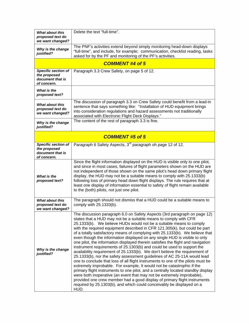
What about this proposed text do we want changed?
Delete the text “full-time”.
Why is the change justified?
The PNF’s activities extend beyond simply monitoring head-down displays “full-time”, and include, for example; communication, checklist reading, tasks asked for by the PF and monitoring of the PF’s activities.
COMMENT #4 of 5 Specific section of the proposed document that is of concern.
Paragraph 3.3 Crew Safety, on page 5 of 12.
What is the proposed text?
What about this proposed text do we want changed?
The discussion of paragraph 3.3 on Crew Safety could benefit from a lead-in sentence that says something like: "Installation of HUD equipment brings into consideration regulations and hazard assessments not traditionally associated with Electronic Flight Deck Displays."
Why is the change justified?
The content of the rest of paragraph 3.3 is fine.
COMMENT #5 of 5 Specific section of the proposed document that is of concern.
Paragraph 6 Safety Aspects, 3rd paragraph oh page 12 of 12.
What is the proposed text?
Since the flight information displayed on the HUD is visible only to one pilot, and since in most cases, failures of flight parameters shown on the HUD are not independent of those shown on the same pilot’s head down primary flight display, the HUD may not be a suitable means to comply with 25.1333(b) following loss of primary head down flight displays. The rule requires that at least one display of information essential to safety of flight remain available to the (both) pilots, not just one pilot.
What about this proposed text do we want changed?
The paragraph should not dismiss that a HUD could be a suitable means to comply with 25.1333(b).
Why is the change justified?
The discussion paragraph 6.0 on Safety Aspects (3rd paragraph on page 12) states that a HUD may not be a suitable means to comply with CFR 25.1333(b). We believe HUDs would not be a suitable means to comply with the required equipment described in CFR 121.305(k), but could be part of a totally satisfactory means of complying with 25.1333(b). We believe that even though the information displayed on any single HUD is visible to only one pilot, the information displayed therein satisfies the flight and navigation instrument requirements of 25.1303(b) and could be used to support the availability requirement of 25.1333(b). We don't believe the requirement of 25.1333(b), nor the safety assessment guidelines of AC 25-11A would lead one to conclude that loss of all flight instruments to one of the pilots must be extremely improbable. For example, It would not be catastrophic if the primary flight instruments to one pilot, and a centrally located standby display were both inoperative (an event that may not be extremely improbable), provided one crew member had a good display of primary flight instruments required by 25.1303(b), and which could conceivably be displayed on a HUD.


Pratt & Whitney 400 Main Street East Hartford, CT 06108
October 22, 2010
Federal Aviation Administration 800 Independence Avenue, SW Washington, D.C. 20591
0 Pratt & Whitney A United Technologies Company
Attention: Ms. Margaret Gilligan, Associate Administrator for Aviation Safety
Subject: Updated ARAC Recommendation, Avionics Systems Harmonization Working Group
References: 1. ARAC Tasking, Federal Register, April 23, 2002 2. TAEIG letter to FAA May 11, 2010
Dear Peggy,
The Transport Airplane and Engine Issues Group and the Avionics System Harmonization Working Group are pleased to submit the attached proposed new appendices to AC25-11A to the FAA as an updated ARAC recommendation. These proposed appendices address Weather Related Displays and Head-Up Displays in accordance with the reference 1 tasking. The Avionics HWG report was originally transmitted to the FAA per the reference 2 letter and included comments from Boeing and Bombardier. The working Group subsequently reviewed those comments and updated the proposed advisory material.
Sincerely yours,
C.R. Bolt Assistant Chair, TAEIG
Copy: Mike Kaszycki - FAA-NWR Clark Badie - Honeywell James Wilborn - FAA-NWR Suzanne Masterson - FAA NWR Ralen Gao - FAA-Washington, D.C. - Office of Rulemaking

: ·~
U.S. Department of Transportation
Federal Aviation Administration
DEC 1 7 2010
Mr. Craig R. Bolt, Assistant Chair Aviation Rulemaking Advisory Committee Pratt & Whitney 400 Main Street, Mail Stop 162-14 East Hartford, CT 06108
Dear Mr. Bolt:
This is in reply to your October 22, 20 IO letter. Your letter transmitted to the FAA the Aviation Rulemaking Advisory Committee's (ARAC) updated recommendations regarding AC/AMC 25-1 lA for Weather Related Displays and Head-Up Displays (HUD). I understand this update is the result of the Avionics Systems Harmonization Working Group's (ASWHG) review of and response to Boeing and Bombardier's comments, attached to the original ARAC transmission in May 11, 2010.
I wish to thank the ARAC, particularly the members associated with TAEIG and its ASHWG that provided resources to develop the report and recommendation. The updated report will be placed on the ARAC website.
Sincerely,
~~\\\~~ Pamela Hamilton-Powell Director, Office of Rulemaking

1. Background and Scope:
Appendix W Weather Displays
This appendix provides additional guidance for displaying weather information in the flight deck. Weather displays provide the flight crew with additional tools to help the flight crew make decisions based on weather information.
Sources of weather information may include, but would not be limited to: onboard, real-time weather, data-linked weather, turbulence information, pilot/air traffic reports, and may be displayed in a variety of graphical or text formats.
Because there are many sources of weather information, it is important that the applicant identify and assess the intended function for a particular source and display of weather information, and apply the guidance contained within this AC/AMC.
2. Key Characteristics In addition to the general guidelines provided in this AC, there are unique aspects of the display of weather information so that the information is being used as intended.
A. The display should enable the flight crew to quickly, accurately, and consistently differentiate among sources of displayed weather, as well as differentiate between timecritical weather information and dated, non-time critical weather information.
B. Weather presentations (display format, the use of colors, labels, data formats, and interaction with other display parameters) should be clear and unambiguous and not result in a flight crew member's misunderstanding or misinterpretation of the weather info1mation being displayed. Weather displays may use red and amber/yellow provided that all of the following criteria are met;
1. The use of color is in compliance with 14 CFR/CS 25.1322, AC 25.1322, and this AC.
2. The use of color is appropriate to the task and context of use, and,
3. The proposed use does not affect the attention getting qualities of flight crew alerting and does not adversely affect the alerting functions across the flight deck, and,
4. Color conventions (such as ARINC 708; AC 20-149) are utilized.
Note: AC 20-149 indicates an exclusion to the acceptability of D0-267 A (paragraph 7 .d) for part 25 airplanes.
1

C. If more than one source of weather information is available to the flight crew, an indication of the weather source selection should be provided.
D. If weather information is displayed as an overlay on an existing display format, both the weather information and the information it overlays should be readily distinguished and correctly interpreted from each other. It also should be consistent with the information it overlays, in terms of position, orientation, range, and altitude.
E. When simultaneously displaying multiple weather sources ( e.g. weather radar and data link weather), each source should be clear and unambiguous and not result in a misunderstanding or misinterpretation of the displayed weather information by the flight crew. This is applicable also for symbols (e.g. winds aloft, lightning) having the same meaning from different weather information sources.
F. Fusion of sensor information to create a single weather image may be acceptable provided the fused weather information meets its intended function, and the fused information is shown to be in compliance with the guidance in this AC (e.g the pilot understands the source of the fused information). When fusing or overlaying multiple weather sources, the resultant combined image should meet its intended function despite any differences in in1age quality, projection, data update rates, data latency, or sensor alignment algorithms.
G. lf weather information is displayed on the HUD, the guidelines of this AC including appendix H need to be considered.
H. When weather is not displayed in real time, some means to identify its relevance ( e.g. time stamp or product age) should be provided. Presenting product age is particularly important when combining information from multiple weather products.
I. If a weather radar looping (anjmation) feature is provided, means to readily identify the total elapsed time of the image compilation should be provided, to avoid potential misinterpretation of the movement of the weather cells.
J. For products that have the ability to present weather for varying altitudes (e.g., potential or reported icing, radar, lightning strikes), information should be presented that allows the ilight crew to distinguish or identify which altitude range applies to each feature.
K. Weather information may include a number of graphical and text information "features" or sets of information ( e.g. text and graphical MET ARS, winds aloft) There should be a means to identify the meaning of each "feature" to ensure that the information is correctly used.
L. If the pilot or system has the ability to turn a weather source on and off, there should be a clear means for the flight crew to determine if it is turned on or off.
M. When weather information is presented in a vertical situation display (VSD), it should be depicted sufficiently wide to contain the weather information that is relevant to the current phase of flight or flight path. In addition:
2

1. Weather information displayed on VSD shall be accurately depicted with respect to the scale factors of the display (i.e., vertical and horizontal), all vertical path information displayed, including glide slope, approach path, or angle of descent.
2. Consideration should be given to making the weather information display width consistent with the display width used by other systems, including Terrain Awareness and Warning System (TA WS), if displayed.
3. On-Board Weather Radar Information On-Board Weather Radar may provide forward-looking weather detection, including windshear and turbulence detection.
The display of on-board weather radar information should be in accordance with the applicable portions of RTCA D0-220, "Minimum Operational Performance Standards for Airborne Weather Radar With Forward-Looking Windshear Capability."
The weather display echoes from precipitation and ground returns should be clear, automatic, timely, concise and distinct for rapid pilot interpretation so flight crews can easily analyze and avoid areas of detected hazards. The radar range, elevation, and azimuth indications should provide sufficient indication to the flight crew to allow for safe avoidance maneuvers.
4. Predictive Windshear Information The display of windshear information, if provided, should be clear, automatic, timely, concise and distinct for rapid pilot interpretation so flight crews can easily detect and avoid areas of windshear activity.
When a windshear threat is detected, the corresponding display may be automatically presented or selected by pilot action, at a range which is appropriate to identify the windshear threat. Pilot workload necessary for its presentation should be minimized and should not take more than one action when the cockpit is configured for normal operating procedures.
The display of a predictive windshear threat, including relative position and azimuth with respect to the nose of the airplane, should be presented in an unambiguous manner to effectively assist the flight crew in responding to the windshear threat; the symbol should be presented in accordance with D0-220.
The size and location of the windshear threat should be presented using a symbol that is sufficient to allow the pilot to recognize and respond to the threat
The range selected by the pilot for the windshear display should be sufficient to allow the pilot to distinguish the event from other displayed information. Amber radial lines may be used to extend from the left and right radial boundaries of the icon extending to the upper edge of the display.
3
5. Safety Aspects Both the loss of weather information plus the display of misleading weather information should be addressed in the functional hazard assessment (FHA). In particular, this should only address failures of the display system that could result in loss of or misleading weather information, not the sensor itself
In accordance with paragraph 4 of this AC, display of misleading weather radar includes the display of weather radar information that would lead the pilot to make a bad decision and introduce a potential hazard. Examples of misleading weather radar information include, but are not limited to: storm cells presented on the display that are not in the correct position, are at the wrong intensity, not displayed when they should be displayed, or mis-registered in the case of a combined (e.g fused) image.
4

AC 25-11A Head-Up Display Appendix
1 INTRODUCTION The material provided in this appendix provides additional guidance related to the unique aspects and characteristics, the design, analysis, testing, and definition of intended functions of head-up displays (HUD) for transport category airplanes.
In most applications, the HUD provides an indication of primary flight references which allow the pilot to rapidly evaluate the aircraft attitude, energy status, and position during the phases of flight for which the HUD is designed. A common objective of HUD information presentation is to enhance pilot performance in such areas as the transition between instrument and visual flight in variable outside visibility conditions. HUDs may be used to display enhanced and synthetic vision imagery, however the scope of this appendix does not include specific guidance for systems that provide this imagery.
This appendix addresses HUDs which are designed for a variety of different operational concepts and intended functions. It includes guidance for HUDs that are intended to be used as a supplemental display, where the HUD contains the minimum information immediately required for the operational task associated with the intended function. It also addresses HUDs that are intended to be used effectively as primary flight displays. This appendix addresses both the installation of a single HUD, typically for use by the left-side pilot, as well as special considerations related to the installation and use of dual HUDs, one for each pilot. These dual HUD special considerations will be called out in the appropriate sections which follow.
For guidance associated with specific operations using a HUD, such as low visibility approach and landing operations, see the relevant requirements and guidance material (e.g. CS-AWO, AC120-28D).
Additional guidance for the design and evaluation of HUDs can be found in ARP 5288, AS 8055 and ARP 5287.
2 HUD FUNCTION The applicant is responsible for identifying the intended function of the HUD. The intended function should include the operational phases of flight, concept of operation, including how, when, and for what purpose the HUD is intended to be used. For example, the HUD systems may provide a head-up display of situational information and/or guidance information that may be used during all phases of flight.
2.1 Primary Flight Information
If the HUD is providing primary flight information, its primary flight information should be presented to allow easy recognition by the pilot while causing no confusion due to ambiguity with similar information presented on other aircraft flight deck displays.
If a HUD displays primary flight information, it is considered the de facto primary flight information while the pilot is using it, even if it is not the pilot's sole display of this information.
Primary fl ight information displayed on the HUD should comply with all the requirements associated with such information in Part 25 (e.g. , §§ 25.1 303(b) and 25.1333(b)). The requirements for arranging primary flight information are specified in § 25.1321 (b). For specific guidance regarding the display of primary flight information see the main body of this AC and also Appendix 1.
1

2.2 Other Information
Other information displayed on a HUD may be dependent on the phases of flight and flight operations supported by the HUD. This add itional information is mainly related to the display of command guidance or situational information.
For example, if the HUD is to be used to monitor the autopilot, the following information should be displayed:
a. Situation information based on independent raw data; b. Autopilot operating mode; c. Autopilot engage status;
c. Autopilot disconnect warning (visual).
Additional information should also be displayed if required to enable the pilot to perform aircraft maneuvers during phases of flight for which the HUD is approved. These may include:
a. Flight path indication; b. Target airspeed references and speed limit indications; c. Target altitude references and altitude awareness (e.g ., DH, MDA) indications; d. Heading or course references.
2.3 Head-Up to Head-Down Transition
Events that may lead to transition between the HUD and the Head Down Display (HOD) should be identified and scenarios developed for evaluation (e.g., simulation, flight test). These scenarios should include systems failures, as well as events leading to unusual attitudes. Transition capability should be shown for all foreseeable modes of upset.
There may be differences between the way in which the head up and head down displays present information (e.g. , flight path, situational, or aircraft performance information). Differences between the head up format and head down format should not create pilot confusion, misinterpretation, unacceptable delay, or otherwise hinder the pilot's transition between the two displays. HUD information should be easy to recogn ize and interpret by the pilot while causing no confusion due to ambiguity with similar information presented on other aircraft flight deck displays.
The HUD symbols should be consistent, but not necessarily identical, with those used on head down instruments to prevent misinterpretation or difficulty in transitioning between the two types of display. Similar symbols on the HUD and on the head down displays should have the same meaning.
The use of similar symbols on the HUD and on the head down displays to represent different parameters is not acceptable.
2.4 Dual HUDs
The applicant should define the operational concept for the use of the dual-HUD installation that details Pilot-Flying/Pilot-Not-Flying (PF/PNF) tasks and responsibilities in regards to using and monitoring head-down displays (HOD) and HU D's during all phases of flight. The Dual HUD concept of operation should specifically address the simultaneous use of the HUD by both pilots during each phase of flight, as well as cross cockpit transfer of control.
2

Single HUD installations where the pilot is likely to use the HUD as a primary flight reference rely on the fact that the PNF will monitor the head-down instruments and alerting systems, for failures of systems, modes, and functions not associated with primary flight displays or HUD.
For the simultaneous use of dual HUDs, a means shall be provided so that the flight crew is able to maintain an equivalent level of awareness of key information not displayed on the HUD (e.g. powerplant indications, alerting messages, aircraft configuration indications).
The operational concept, defined by the applicant and used during the piloted evaluation of the installation, should account for the expected roles and responsibilities of the PF and the PNF,
considering the following:
• When a pilot is using a HUD as the PFD, the visual head down indications may not receive the same level of vigilance by that pilot, compared to a pilot using the head down PFD.
• How the scan of the head down instruments is ensured during all phases of flight, and if not, what compensating design features are needed to help the flightcrew maintain awareness of key information (e.g., powerplant indications, alerting messages, aircraft configuration indication) not displayed on the HUD.
• Which pilot is expected to maintain a scan of head down instrument indications and how often. For any case where the scan of head down information is not full-time for at least one pilot, the design should have compensating design features which ensure an equivalent level of timeliness and awareness of the information provided by the head down visual indications.
• Cautions and warnings, if the visual information, equivalent to the head down PFD indications, is not presented in the HUD, the design should have compensating features that ensure the pilot using the HUD is made aware with no additional delay and able to respond with no reduction of task performance or degraded safety
For those phases of flight where airworthiness approval is predicated on the use of the HUD, or when it can be reasonably expected that the pilot will operate primarily by reference to the HUD, the objective is to not redirect attention of the pilot flying to another display when an immediate maneuver is required (e.g., resolution advisory, windshear). The applicant should either provide in the HUD the guidance, warnings, and annunciations of certain systems, if installed, such as a Terrain Awareness and Warning System (TAWS), or a traffic alert and collision avoidance system (TCAS) and a wind shear detection system, or provide compensating design features ( e.g., a combinations of means such as control system protections and an unambiguous reversion message in the HUD) and procedures that ensure the pilot has equivalently effective visual information for timely awareness and satisfactory response to these alerts.
A global (re-)assessment of the alerting function should be performed to assess the HUDs alerting design and techniques together with the Alerting attention getting (visual MW and MC/aural) and other alerting information in the flight deck to ensure that timely crew awareness and response are always achieved when needed.
3

3 INSTALLATION
3.1 HUD Field of View
The design of the HUD installation should provide adequate display field-of-view in order for the HUD to function as intended in all anticipated flight attitudes, aircraft configurations, or environmental conditions, such as crosswinds, for which it is approved. All airworth iness and operational limitations should be specified in the AFM.
The optical characteristics of the HUD make the ability to fully view essential flight information more sensitive to the pilot's eye position, compared to head down displays. The HUD design eye-box is a three dimensional volume, specified by the manufacturer, within which display visibility requirements are met. For compliance to §§ 25. 773 and 25.1301 , whenever the pilot's eyes are within the design eyebox, the required flight information will be visible in the HUD. The minimum monocular field of view (FOV) requ ired to display this required flight information, should include the center of the FOV and must be specified by the manufacturer.
The fundamental requirements for instrument arrangement and visibility that are found in §§ 25.1321, 25. 773 and 25. 777 apply to these devices. Section 25. 1321 requires that each flight instrument for use by any pilot be plainly visible at that pilot's station, with minimum practicable deviation from the normal position and forward line of vision. Advisory Circular (AC) 25.773-1 defines the Design Eye Position (DEP) as a single point that meets the requirements of§§ 25.773 and 25.777. For certification purposes, the DEP is the pilot's normal seated position, and fixed markers or other means should be installed at each pilot station to enable the pilots to position themselves in their seats at the DEP for an optimum combination of outside visibility and instrument scan. The Design Eye Box should be positioned around the Design Eye Position.
The visibility of the displayed HUD symbols must not be unduly sensitive to pilot head movements in all expected flight conditions. In the event of a total loss of the display as a result of a head movement, the pilot must be able to regain the display rapidly and without difficulty.
The lateral and vertical dimensions of the eyebox represent the total movement of a monocular viewing instrument with a 1/4 in. (6.35 mm) entrance aperture (pupil). The eye-box longitudinal dimension represents the total fore-aft movement over which the requirement of this specification is met. (Reference SAE AS8055).
The HUD design eyebox should be laterally and vertically positioned around the respective pilot's design eye position (DEP), and be large enough that the required flight information will be visible to the pilot at the minimum displacements from the DEP listed below. When the HUD is a Primary Flight Display, or when airworthiness approval is predicated on the use of the HUD, or when the pilot can be reasonably expected to operate primarily by reference to the HUD, larger minimum design eyebox dimensions, than those shown below, may be necessary.
Lateral: 1.5 inches left and right from the DEP (three inches wide)
Vertical: 1.0 inches up and down from the DEP (two inches high)
Longitudinal: 2.0 inches fore and aft from the DEP (4 inches deep)
The HUD installation must comply with §§ 25.1321, 25. 773 and accommodate pilots from 5'2" to 6'3" tall (per 25.777), seated with seat belts fastened and positioned at the DEP.
4

3.2 Obstruction of View
When installed, whether deployed or not, the HUD equipment must not create additional significant obstructions to either pilot's compartment view(§ 25.773). The equipment must not restrict either pilot's view of any controls, indicators or other flight instruments.
The HUD shou ld not significantly degrade the necessary pilot compartment view of the outside world for normal, non-normal, or emergency flight maneuvers during any phase of flight for a pilot seated at the DEP. The HUD should be evaluated to ensure that it does not significantly affect the ability of any crewmember to spot other traffic, distinctly see approach lights, runways, signs, markings, or other aspects of the external visual scene.
The optical performance of the HUD must not degrade, distort or detract from the pilot's view of external references or in regards to seeing and avoiding other aircraft such that it would not enable them to safely perform any maneuvers within the operating limits of the airplane (§25.773). Where the windshield optically modifies the pilot's view of the outside world, the conformal HUD symbols must be optically consistent with the perceived outside view. The combination of the windshield and the HUD must meet the requirements of§ 25. 773(a)(1 ).
The optical qualities of the HUD should be uniform across the entire field of view. When viewed by both eyes from any off-center position within the eyebox, non-uniformities shall not produce perceivable differences in binocular view. Additional guidance is provided in ARP 5288.
3.3 Crew Safety
Installation of HUD equipment brings into consideration potential physical hazards not traditionally associated with head down electronic flight deck displays.
The HUD system must be designed and installed to prevent the possibility of pilot injury in the event of an accident or any other foreseeable circumstance such as turbulence, hard landing, bird strike, etc. The installation of the HUD, including overhead unit and combiner, must comply with the head injury criteria (HIC) of§ 25.562 (c)(5). Additionally, the HUD installation must comply with the retention requirements of§ 25.789(a) and occupant injury requirements of§§ 25.785 (d) and (k).
For a dual HUD installation, there is the potential for both pilots to experience an incapacitating injury as a result of flight or gust loads. This becomes a safety of flight issue, since the entire flightcrew would be incapacitated. The types of injuries of concern may be long duration, low impact, high load, as opposed to the high impact, short duration injuries assessed by HIC. A dedicated method of compliance may be needed should analysis of the installation geometry indicate that flight or gust loads will produce occupant contact with the HUD installation.
For compliance to§§ 25.803, 25.1307, 25.1411 and 25.1447, the HUD installation must not interfere with or restrict the use of other installed equipment such as emergency oxygen masks, headsets, or microphones. The installation of the HUD must not adversely affect the emergency egress provisions for the flight crew, or significantly interfere with crew access. The system must not hinder the crew's movement while conducting any flight procedures.
3.4 HUD Controls
For compliance to§ 25.777, the means of controll ing the HUD, including its configuration and display modes, must be visible to, identifiable, accessible, and within the reach of, the pilots from their normal seated position. For compliance to§§ 25. 777, 25. 789 and 25.1301 , the position and movement of the HUD controls must not lead to inadvertent operation. For compliance to§ 25.1381 , the HUD controls must be adequately illuminated for all normal ambient lighting conditions, and must not create any objectionable reflections on the HUD or other flight
5

instruments. Unless a fixed level of illumination is satisfactory under all lighting conditions, there should be a means to control its intensity.
To the greatest extent practicable, the HUD controls should be integrated with other associated flight deck controls, to minimize the crew workload associated with HUD operation and to enable flightcrew awareness.
HUD controls, including the controls to change or select HUD modes, should be implemented to minimize pilot workload for data selection or data entry and allow the pilot to easily view and perform all mode control selections from his seated position.
4 INFORMATION PRESENTATION
4.1 Displayed Information
The HUD information display requirements will depend on the intended function of the HUD. Specific guidance for displayed information is contained within the main body and Appendix 1 of this AC. In addition, the following sections provide guidance related to unique characteristics of the HUD. As in the case of other flight deck displays, new and/or novel display formats may be subject to an Authority human factors pilot interface evaluation(s).
4.1.1 Alternate Formats of Displaying Primary Flight Information
There may be certain operations and phases of flight during which certain primary flight reference indications in the HUD do not need to have the analog cues for trend, deviation, and quick glance awareness that would normally be necessary. For example, during the precision approach phase, HUD formats have been accepted that provide a digital only display of airspeed and altitude. Acceptance of these displays has been predicated on the availability of compensating features that provide clear and distinct warning to the flight crew when these and certain other parameters exceed well-defined tolerances around the nominal approach state (e.g ., approach warning), and these warnings have associated procedures that require the termination of the approach.
Formats with digital-only display of primary flight information (e.g., airspeed, altitude, attitude, heading) should be demonstrated to provide at least:
• a satisfactory level of task performance,
• a satisfactory awareness of proximity to limit values, like Vs, VMO and VFE, or
• a satisfactory means to avoid violating such limits.
If a different display format is used for go-around than that used for the approach, the format transition should occur automatically as a result of the normal go-around or missed approach procedure.
Changes in the display format and primary flight data arrangement should be minimized to prevent confusion and to enhance the pilots' ability to interpret vital data.
4.1.2 Aircraft Control Considerations
For those phases of flight where airworthiness approval is predicated on the use of the HUD, or when it can be reasonably expected that the pilot will operate primarily by reference to the HUD, the HUD should adequately provide:
6

• information to permit instant pilot evaluation of the airplane's flight state and position. This should be shown to be adequate for manually controlling the airplane, and for monitoring the performance of the automatic flight control system. Use of the HUD for manual control of the airplane and monitoring of the automatic flight control system, should not require exceptional skill, excessive workload, or excessive reference to other flight displays.
• cues for the pilot to instantly recognize unusual attitudes and shall not hinder its recovery. If the HUD is designed to provide guidance or information for recovery from upsets or unusual attitudes, recovery steering guidance commands should be distinct from, and not confused with, orientation symbology such as horizon "pointers." This capability should be shown for all foreseeable modes of upset, including crew mishandling, autopilot failure (including "slowovers"), and turbulence/gust encounters.
4.1 .3 Airspeed Considerations
As with other electronic flight displays, the HUD airspeed indications may not typically show the entire range of airspeed. Section 25.1541 (b)(2) of the Federal Aviation Regulations states: "The airplane must contain - Any additional information, instrument markings, and placards required for the safe operation if there are unusual design, operating, or handling characteristics. "
Low speed awareness cues presented on the HUD should provide adequate visual cues to the pilot that the airspeed is below the reference operating speed for the airplane configuration (i.e., weight, flap setting, landing gear position, etc.); similarly, high speed awareness cues should provide adequate visual cues to the pilot that the airspeed is approaching an established upper limit that may result in a hazardous operating condition.
The cues should be readily distinguishable from other markings such as V-speeds and speed targets (bugs). The cues should not only indicate the boundary value of speed limit, but also clearly distinguish between the normal speed range and the unsafe speed range beyond those limiting values. Cross-hatching may be acceptable to provide delineation between zones of different meaning.
4.1 .4 Flight Path Considerations
An indication of the aircraft's velocity vector, or flight path vector, is considered essential to most HUD applications. Earth-referenced flight path display information provides an instantaneous indication of where the aircraft is actually going. During an approach this information can be used to indicate the aircraft's impact or touchdown point on the runway. The earth referenced flight path will show the effects of wind on the motion of the airplane. The flight path vector can be used by the pilot to set a precise climb or dive angle relative to the conformal outside scene or relative to the HUD's flight path (pitch) reference scale and horizon displays. In the lateral axis the flight path symbols should indicate the aircraft track relative to the boresight.
Air mass derived flight path may be displayed as an alternative, but will not show the effects of wind on the motion of the airplane. In this case the lateral orientation of the flight path display represents the aircraft's sideslip while the vertical position relative to the reference symbol represents the aircraft's angle of attack.
The type of flight path information displayed (e.g., earth referenced, air mass) may be dependent on the operational characteristics of a particular aircraft and the phase of flight during which the flight path is to be displayed.
7

4.1.5 Attitude Considerations
An accurate, easy, quick glance interpretation of attitude by the pilot should be possible for all unusual attitude situations and command guidance display configurations. The pitch attitude display should be such that during all maneuvers a horizon reference remains visible with enough margin to allow the pilot to recognize pitch and roll orientation. For HUDs that are capable of displaying the horizon conformally, display of a non-conformal horizon reference should be distinctly different than the display of a conformal horizon reference.
In addition, extreme attitude symbology and automatically decluttering the HUD at extreme attitudes has been found acceptable (extreme attitude symbology should not be visible during normal maneuvering).
When the HUD is designed not to be used for recovery from unusual attitude, there should be: • compensating features (e.g., characteristics of the airplane and the HUD system), • immediate direction to the pilot to use the head down PFD for recovery, and • satisfactory demonstration of timely recognition and correct recovery maneuvers.
4.2 Display Compatibility
The content, arrangement and format of the HUD information should be sufficiently compatible and consistent with the head down displays to preclude pilot confusion, misinterpretation, or excessive cognitive workload. Transitions between the HUD and head down displays, whether required by navigation duties, failure conditions, unusual airplane attitudes, or other reasons, should not present difficulties in data interpretation or delays/interruptions in the flight crew's ability to manually control the airplane or to monitor the automatic flight control system.
The HUD and HOD formats and data sources need to be compatible to ensure that the same information presented on both displays have the same intended meaning. HUD and HOD parameters should be consistent to avoid misinterpretation of similar information, but the display presentations need not be identical.
Deviation from these guidelines may be unavoidable due to conflict with other information display characteristics or requirements unique to head up displays. These may include minimization of display clutter, minimization of excessive symbol flashing, and the presentation of certain information conformal to the outside scene. Deviations from these guidelines will require additional pilot evaluation.
The following should be considered:
(a) Symbols that have the same meaning should be the same format;
(b) Information (symbols) should appear in the same general location relative to other information;
(c) Alphanumeric readouts should have the same resolution, units, and labeling (e.g., the command reference indication for "vertical speed" should be displayed in the same foot-perminute increments and labeled with the same characters as the head-down displays);
(d) Analogue scales or dials should have the same range and dynamic operation (e.g., a Glideslope Deviation Scale displayed head-up should have the same displayed range as the Glideslope Deviation Scale displayed head-down, and the direction of movement should be consistent);
(e) FGS modes (e.g. autopilot, flight director, autothrust) and state transitions (e.g. land 2 to land 3) should be displayed on the HUD, and except for the use of colour, should be displayed using consistent methods (e.g., the method used head-down to indicate a flight director mode transitioning from armed to captured should also be used head-up); and
8

(f) Information sources should be consistent between the HUD and the head-down displays used by the same pilot.
(g) When command information (i.e., flight director commands) is displayed on the HUD in addition to the head-down displays, the HUD depiction and guidance cue deviation "scaling" needs to be consistent with that used on the head-down displays. This is intended to provide comparable pilot performance and workload when using either head-up or head-down displays.
(h) The unique information concerning current HUD system mode, reference data, status state transitions, and alert information that is displayed to the pilot flying on the HUD, should also be displayed to the pilot not flying using consistent nomenclature to ensure unambiguous awareness of the HUD operation.
4.3 Indications and Alerts
In order to demonstrate compliance with 25.1322 and to the extent that most HUDs are currently single color (monochrome) devices, caution and warning information should be emphasized with the appropriate use of attention-getting properties such as flashing, outline boxes, brightness, size, and/or location to compensate for the lack of color coding. A consistent documented philosophy should be developed for each alert level and conflicts of meaning with head-down display format changes will need to be avoided.
Additional guidance is in AC 25. 1329 and AC 25.1322 and the associated regulations.
4.4 Display Clutter
Clutter has been addressed elsewhere in this A(M)C. However, for a HUD, special attention is needed regarding the effects of clutter affecting the see-through characteristics of the display.
5 VISUAL CHARACTERISTICS The following paragraphs highlight some areas, which are related to performance aspects that are specific to the HUD. ARP5288 and AS8055 provide performance guidelines for a head-up display. As stated in Chapter 3, the applicant should notify the Airworthiness Authority if any visual display characteristics do not meet the guidelines in AS8055 and ARP 5288.
5.1 Luminance Control
The display luminance (brightness) should be satisfactory in the presence of dynamically changing background (ambient) lighting conditions (0 to 10,000 fl per AS8055), so that the HUD data is visible to the pilot(s). To accomplish this, the HUD may have both manual and automatic luminance control capabilities. It is recommended that automatic control is provided in addition to the manual control. Manual control of the HUD brightness level should be available to the flight crew in order to provide the means to set a reference level for automatic brightness control. If automatic control for display brightness is not provided, it should be shown that a single manual setting is satisfactory for the range of lighting conditions encountered during all foreseeable operational conditions and against expected external scenes. Readability of the displays should be satisfactory in all foreseeable operating and ambient lighting conditions. AS8055 and ARP 5288 provide guidelines for contrast and luminance control.
5.2 Alignment
Proper HUD alignment is needed to match conformal display parameters as close as possible to the outside (real) world, depending on the intended function of those parameters.
If the HUD combiner is stowable, means should be provided to ensure that it is fully deployed prior to using the symbology for aircraft control. The HUD system shall provide means to alert the
9

pilot if the position of the combiner causes normally conformal data to become misaligned in a manner that may result in display of misleading information.
The range of motion of conformal symbology can present certain challenges in rapidly changing and high crosswind conditions. In certain cases, the motion of the guidance and the primary reference cue may be limited by the field of view.
It should be shown that, in such cases, the guidance remains usable and that there is a positive indication that it is no longer conformal with the outside scene. It should also be shown that there is no interference between the indications of primary flight information and the flight guidance cues.
5.2.1 Symbol Positioning Accuracy (External)
External Symbol Positioning Accuracy, or Display Accuracy, is a measure of the relative conformality of the HUD display with respect to the real world view seen by the pilot through the combiner and windshield from any eye position within the HUD Eyebox. Display Accuracy is a monocular measurement, and, for a fixed field point, is numerically equal to the angular difference between the position of a real world feature as seen through the combiner and windshield, and the HUD projected symbology.
The total HUD system display accuracy error budget (excluding sensor and windshield errors) includes installation errors, digitization errors, electronic gain and offset errors, optical errors, combiner positioning errors, errors associated with the CRT and yoke (if applicable), misalignment errors, environmental conditions (i.e., temperature and vibration). and component variations. Optical errors are both head position and field angle dependent and are comprised of three sources: uncompensated pupil and field errors originating in the optical system aberrations, image distortion errors, and manufacturing variations. The optical errors are statistically determined by sampling the HUD FOV and Eyebox. (See 4.2.1 O of SAE 8055 for a discussion of field of view and Eyebox sampling);
• The optical errors shall represent 95.4% (2 sigma) of all sampled points. • The display accuracy errors are characterized in both the horizontal and vertical planes. • Total display accuracy shall be characterized as the root-sum square (RSS) errors of
these two component errors.
All display errors shall be minimized across the display field of view consistent with the intended function of the HUD. The following are the allowable display accuracy errors for a conformal HUD as measured from the HUD Eye Reference Point:
• HUD Boresight • <= 10° diameter • <= 30° diameter • >30° diameter
<= 5.0 mrad <= 7.5 mrad (2 Sigma) <=10.0 mrad (2 Sigma) < 10 mrad + kr[(FOV)(in degrees) - 30)] (2 Sigma) kr = 0.2 mrad of error per degree of FOV
The HUD manufacturer shall specify the maximum allowable installation error. In no case shall the display accuracy error tolerances cause hazardously misleading data to be presented to the pilot viewing the HUD.
10
5.2.2 Symbol Positioning Alignment
Symbols which are interpreted relative to each other shall be aligned to preclude erroneous interpretation of information. Symbols which are not interpreted relative to each other may overlap but shall not cause erroneous interpretation of display data, even when they overlap.
5.2.3 Combiner Position Alignment: The HUD system shall provide a warning to the pilot if the position of the combiner causes conformal data to become hazardously misaligned.
5.3 Reflections and Glare
The HUD must be free of glare and reflections that could interfere with the normal duties of the minimum flight crew (per 14 CFR 25.1523 and 25.777).
5.4 Ghost Images
The visibility of ghost images within the HUD of external surfaces must be minimized so as not to impair the pilot's ability to use the display.
A ghost image is an undesired image appearing at the image plane of an optical system. Reflected light may form an image near the plane of the primary image. This may result in a false image of the object or an out-of-focus image of a bright source of light in the field of the optical system (e.g., a "ghost image").
5.5 Design Eye Position
The HUD Design Eye Position (DEP) must be the same as that defined for the basic cockpit in accordance with AC 25.773-1. The Design Eyebox must contain the DEP. The displayed symbols which are necessary to perform the required tasks must be visible to the pilot from the DEP and the symbols must be positioned such that excessive eye movements are not required to scan elements of the display.
5.6 Field Of View The Field of View should be established by taking into consideration the intended operational environment and potential aircraft configurations.
5. 7 Head Motion The visibility of the displayed symbols must not be unduly sensitive to pilot head movements in all expected flight cond itions. In the event of a total loss of the display as a result of a head movement, the pilot must be able to regain the display rapidly and without difficulty.
5.8 Accuracy and Stability The system operation should not be adversely affected by aircraft manoeuvring or changes in attitude encountered in normal service. The accuracy of positioning of symbols must be commensurate with their intended use. Motion of non-conformal symbols must be smooth, not sluggish or jerky, and consistent with aircraft control response. Symbols must be stable with no discernible flicker or jitter.
5.9 HUD Optical Performance As far as practicable, the optical performance of the HUD must not degrade, distort or detract from the pilot's view of external references or of other aircraft. Where the windshield optically modifies the pilot's view of the outside world, the conformal HUD symbols must be optically consistent with the perceived outside view. The combination of the windshield and the HUD must meet the requirements of 14 CFR/CS 25.773(a)(1).
11

6 SAFETY ASPECTS The installation of HUD systems in flight decks may introduce complex functional interrelationships between the pilots and other display and control systems. Consequently, a Functional Hazard Assessment (FHA) which requires a top down approach, from an airplane level perspective, should be developed in accordance with FAR/CS 25.1309. Development of a FHA for a particular installation requires careful consideration of the role the HUD plays within the flight deck in terms of integrity of function and availability of function, as well the operational concept of the installation to be certified (dual vs single, type and amount of information displayed, etc.). Chapter 4 of this AC provides material that may be useful in supporting the FHA preparation.
All alleviating flight crew actions that are considered in the HUD safety analysis need to be validated for incorporation in the airplane flight manual procedures section or for inclusion in typespecific training.
Since the flight information displayed on the HUD is visible only to one pilot, and since in most cases,
failures of flight parameters shown on the HUD are not independent of those shown on the same pilot's
head down primary flight display, the applicant should demonstrate that the HUD only provides a suitable
means to comply with 25.1333(b) following loss of primary head down flight display to the pilot using the
HUD. The rule requires that at least one display of information essential to safety of flight remain
available to the (both) pilots, not just one pilot.
7 CONTINUED AIRWORTHINESS
Depending on the type of operation and the intended function of the HUD, instructions for the continued airworthiness of a display system and its components have to be prepared to show compliance with §§ 25.1309 and 25.1529 (including Appendix H)
8 FLIGHT DAT A RECORDING
The installation of HUDs has design aspects and unique operational characteristics requiring specific accident recording considerations. HUD guidance modes and status (in use or inoperative) and display declutter mode shou ld be considered to be recorded to comply with§ 25.1459(e) and 121.344.
12

1. Background and Scope:
Appendix W Weather Displays
This appendix provides additional guidance for displaying weather information in the flight deck. Weather displays provide the flight crew with additional tools to help the flight crew make decisions based on weather information.
Sources of weather information may include, but would not be limited to: onboard, real-time weather, data-linked weather, turbulence information, pilot/air traffic reports, and may be displayed in a variety of graphical or text formats .
Because there are many sources of weather information, it is important that the applicant identify and assess the intended function for a particular source and display of weather information, and apply the guidance contained within this AC/AMC.
2. Key Characteristics In addition to the general guidelines provided in this AC, there are unique aspects of the display of weather information so that the information is being used as intended.
A. The display should enable the flight crew to quickly, accurately, and consistently differentiate among sources of displayed weather, as well as differentiate between timecritical weather information and dated, non-time critical weather infonnation.
8 . Weather presentations (display format, the use of colors, labels, data fonnats, and interaction with other display parameters) should be clear and unambiguous and not result in a flight crew member's misunderstanding or misinterpretation of the weather information being displayed. Weather displays may use red and amber/yellow provided that all of the following criteria are met;
I. The use of color is in compliance with 14 CFR/CS 25 .1322, AC 25.1322, and this AC.
2. The use of color is appropriate to the task and context of use, and,
3. The proposed use does not affect the attention getting qua! ities of flight crew alerting and does not adversely affect the alerting functions across the flight deck, and,
4 . Color conventions (such as ARINC 708; AC 20-149) are utilized.
Note: AC 20-149 indicates an exclusion to the acceptabi lity of D0-267 A (paragraph 7.d) for part 25 airplanes.
1

I ~ ---
C. If more than one source of weather information is available to the flight crew, an indication of the weather source selection should be provided.
D. If weather information is displayed as an overlay on an existing display format, both the weather information and the information it overlays should be readily distinguished and correctly interpreted from each other. It also should be consistent with the information it overlays, in terms of position, orientation, range, and altitude.
E. When simultaneously displaying multiple weather sources (e.g. weather radar and data link weather), each source should be clear and unambiguous and not result in a misunderstanding or misinterpretation of the displayed weather information by the flight crew. This is applicable also for symbols (e.g. winds aloft, lightning) having the same meaning from different weather information sources.
F. Fusion of sensor information to create a single weather image may be acceptable provided the fused weather information meets its intended function, and the fused information is shown to be in compliance with the guidance in this AC (e.g the pilot understands the source of the fused information). When fusing or overlaying multiple weather sources, the resultant combined image should meet its intended function despite any differences in image quality, projection, data update rates, data latency, or sensor alignment algorithms.
G. If weather information is displayed on the HUD, the guidelines of this AC including appendix H need to be considered.
H. When weather is not displayed in real time, some means to identify its relevance (e.g. time stamp or product age) should be provided. Presenting product age is particularly important when combining information from multiple weather products.
I. If a weather radar looping (animation) feature is provided, means to readily identify the total elapsed time of the image compilation should be provided, to avoid potential misinterpretation of the movement of the weather cells.
J . For products that have the ability to present weather for varying altitudes (e.g., potential or reported icing, radar, lightning strikes), infonnation should be presented that allows the flight crew to distinguish or identify which altitude range applies to each feature,,.
K. Weather information may include a number of graphical and text information "features" or sets of infonnation (e.g. text and graphical METARS, winds aloft) There should be a means to identify the meaning of each "feature" to ensure that the information is correctly used.
L. If the pilot or svstem has the ability to turn a weather source on and off, there should be a clear means for the flight crew to determine if it is turned on or off.
M. When weather information is presented in a vertical situation display (VSD), it should be depicted sufficiently wide to contain the weather information that is relevant to the current phase of flight or flight path. In addition:
2
{"oeleted: s are being presented.
~ eted_:-"-1 _____ __,

I. Weather information displayed on VSD shall be accurately depicted with respect to the scale factors of the display (i.e., vertical and horizontal), all vertical path information displayed, including glide slope, approach path, or angle of descent.
2. Consideration should be given to making the weather information display width consistent with the display width used by other systems, including Terrain Awareness and Warning System (TA WS), if displayed.
3. On-Board Weather Radar Information On-Board Weather Radar may provide forward-looking weather detection, including windshear and turbulence detection.
The display of on-board weather radar information should be in accordance with the applicable portions of RTCA D0-220, "Minimum Operational Performance Standards for Airborne Weather Radar With Forward-Looking Windshear Capability."
The weather display echoes from precipitation and ground returns should be clear, automatic, timely, concise and distinct for rapid pilot interpretation so flight crews can easily analyze and avoid areas of detected hazards. The radar range, elevation, and azimuth indications should provide sufficient indication to the flight crew to allow for safe avoidance maneuvers.
4. Predictive Windshear Information The display ofwindshear information, if provided, should be clear, automatic, timely, concise and distinct for rapid pilot interpretation so flight crews can easily detect and avoid areas of windshear activity. ·
When a windshear threat is detected, the corresponding display may be automatically presented or selected by pilot action, at a range which is appropriate to identify the windshear threat. Pilot workload necessary for its presentation should be minimized and should not take more than one action when the cockpit is configured for normal operating procedures.
The display of a predictive windshear threat, including relative position and azimuth with respect to the nose of the airplane, should be presented in an unambiguous manner to effectively assist the flight crew in responding to the windshear threat; the symbol should be presented in accordance with D0-220.
The size and location of the windshear threat should be presented using a symbol that is sufficient to allow the pilot to recognize and respond to the threat
The range selected by the pilot for the windshear display should be sufficient to allow the pilot to distinguish the event from other displayed information. Amber radial lines may be used to extend from the left and right radial boundaries of the icon extending to the upper edge of the display.
3

5. Safety Aspects Both the loss of weather information plus the display of misleading weather information should be addressed in the functional hazard assessment (FHA). In particular, this should only address failures of the display system that could result in loss of or misleading weather information, not the sensor itself.
In accordance with paragraph 4 of this AC, display of misleading weather radar includes the display of weather radar information that would lead the pilot to make a bad decision and introduce a potential hazard. Examples of misleading weather radar information include, but are not limited to: storm cells presented on the display that are not in the correct position, are at the wrong intensity, not displayed when they should be displayed, or mis-registered in the case of a combined (e.g fused) image.
4

AC 25-11A Head-Up Display Appendix
1 INTRODUCTION The material provided in this appendix provides additional guidance related to the unique aspects and characteristics, the design, analysis, testing, and definition of intended functions of head-up displays (HUD) for transport category airplanes.
In most applications, the HUD provides an indication of primary flight references which allow the pilot to rapidly evaluate the aircraft attitude, energy status, and position during the phases of flight for which the HUD is designed. A common objective of HUD information presentation is to enhance pilot performance in such areas as the transition between instrument and visual flight in variable outside visibility conditions. HUDs may be used to display enhanced and synthetic vision imagery, however the scope of this appendix does not include specific guidance for systems that provide this imagery.
This appendix addresses HUDs which are designed for a variety of different operational concepts and intended functions. It includes guidance for HUDs that are intended to be used as a supplemental display, where the HUD contains the minimum information immediately required for the operational task associated with the intended function. It also addresses HUDs that are intended to be used effectively as primary fl ight displays. This appendix addresses both the installation of a single HUD, typically for use by the left-side pilot, as well as special considerations related to the installation and use of dual HUDs, one for each pilot. These dual HUD special considerations will be called out in the appropriate sections which follow.
For guidance associated with specific operations using a HUD, such as low visibility approach and landing operations, see the relevant requirements and guidance material (e.g. CS-AWO, AC120-28D).
Additional guidance for the design and evaluation of HUDs can be found in ARP 5288, AS 8055 and ARP 5287.
2 HUD FUNCTION The applicant is responsible for identifying the intended function of the HUD. The intended function should include the operational phases of flight, concept of operation, including how, when, and for what purpose the HUD is intended to be used. For example, the HUD systems may provide a head-up display of situational information and/or guidance information that may be used during all phases of flight.
2.1 Primary Flight Information
If the HUD is providing primary flight information, its primary flight information should be presented to allow easy recognition by the pilot while causing no confusion due to ambiguity with similar information presented on other aircraft flight deck displays.
If a HUD displays primary flight information, it is considered the de facto primary flight information while the pilot is using it, even if it is not the pilot's sole display of this information.
Primary fl ight information displayed on the HUD should comply with all the requirements associated with such information in Part 25 (e.g., §§ 25.1 303(b) and 25.1333(b)). The requirements for arranging primary flight information are specified in § 25.1321 (b). For specific guidance regarding the display of primary flight information see the main body of this AC and also Appendix 1.
1

2.2 Other Information
Other information displayed on a HUD may be dependent on the phases of fl ight and flight operations supported by the HUD. This additional information is mainly related to the display of command guidance or situational information.
For example, if the HUD is to be used to monitor the autopilot, the following information should be displayed:
a. Situation information based on independent raw data; b. Autopilot operating mode; c. Autopilot engage status: c. Autopilot disconnect warning (visual).
Additional information should also be displayed if required to enable the pilot to perform aircraft maneuvers during phases of flight for which the HUD is approved. These may include:
a. Flight path indication; b. Target airspeed references and speed limit indications; c. Target altitude references and altitude awareness (e.g., DH, MDA) indications; d. Heading or course references.
2.3 Head-Up to Head-Down Transition
Events that may lead to transition between the HUD and the Head Down Display (HOD) should be identified and scenarios developed for evaluation (e.g., simulation, flight test). These scenarios should include systems failures, as well as events leading to unusual attitudes. Transition capability should be shown for all foreseeable modes of upset.
There may be differences between the way in which the head up and head down displays present information (e.g., flight path, situational, or aircraft performance information). Differences between the head up format and head down format should not create pilot confusion, misinterpretation, unacceptable delay, or otherwise hinder the pilot's transition between the two displays. HUD information should be easy to recognize and interpret by the pilot while causing no confusion due to ambiguity with similar information presented on other aircraft flight deck displays.
The HUD symbols should be consistent, but not necessari ly identical, with those used on head down instruments to prevent misinterpretation or difficulty in transitioning between the two types of display. Similar symbols on the HUD and on the head down displays should have the same meaning.
The use of similar symbols on the HUD and on the head down displays to represent different parameters is not acceptable.
2.4 Dual HUDs
The applicant should define the operational concept for the use of the dual-HUD installation that details Pilot-Flying/Pilot-Not-Flying (PF/PNF) tasks and responsibilities in regards to using and monitoring head-down displays (HDD) and HUD's during all phases of flight. The Dual HUD concept of operation should specifically address the simultaneous use of the HUD by both pilots during each phase of flight, as well as cross cockpit transfer of control.
2

Single HUD installations where the pilot is likely to use the HUD as a primary flight reference rely on the fact that the PNF will monito!Jhe head-down j ri_s!ru_rn~nJ?.~r1.d_aJerti_l'lg_ systems, for failures of systems, modes, and functions not associated with primary flight displays or HUD.
. .. For the simultaneous use of dual HUDs, ,e means shall be provided so that the flight crew i~_a,l_)le __ ',. \.:: ... to maintain an equivalent level of awareness of key information not displayed on the HUD (e.g. ., ... powerplant indications, alerting messages, aircraft configuration indications).
The operational concept, defined by the applicant and used during the piloted evaluation of the installation, should account for the expected roles and responsibilities of the PF and the PNF, considering the fol lowing:
• When a pilot is using a HUD as the PFD, the visual head down indications may not receive the same level of vigi lance by that pilot, compared to a pilot using the head down PFD.
• How the scan of the head down instruments is ensured during all phases of flight, and if not, what compensating design features are needed to help the flightcrew maintain awareness of key information (e.g., powerplant indications, alerting messages, aircraft configuration indication} not displayed on the HUD.
• Which pilot is expected to maintain a scan of head down instrument indications and how often. For any case where the scan of head down information is not full-time for at least one pilot, the design should have compensating design features which ensure an equivalent level of timeliness and awareness of the information provided by the head down visual indications.
• Cautions and warnings, if the visual information, equivalent to the head down PFD indications, is not presented in the HUD, the design should have compensating features that ensure the pilot using the HUD is made aware with no additional delay and able to respond with no reduction of task performance or degraded safety
For those phases of flight where airworthiness approval is predicated on the use of the HUD, or when it can be reasonably expected that the pi lot will operate primarily by reference to the HUD, the objective is to not redirect attention of the pilot flying to another display when an immediate maneuver is required (e.g., resolution advisory, windshear). The applicant should either provide in the HUD the guidance, warnings, and annunciations of certain systems, if installed, such as a Terrain Awareness and Warning System (TAWS}, or a traffic alert and collision avoidance system (TCAS) and a wind shear detection system, or provide compensating design features ( e.g., a combinations of means such as control system protections and an unambiguous reversion message in the HUD) and procedures that ensure the pilot has equivalently effective visual information for timely awareness and satisfactory response to these alerts.
A global (re-}assessment of the alerting function should be performed to assess the HUDs alerting design and techniques together with the Alerting attention getting (visual MW and MC/aural) and other alerting information in the flight deck to ensure that timely crew awareness and response are always achieved when needed.
3
~
Comment [H1]: Per feedback received during the TAEIG report, PNF will have other dut ies including reviewing checklist, performing communicat,ons, etc, and will not monitor " full 1,me·
Deleted: .
Deleted: full-time
Deleted: .
Deleted: the applicant should demonstrate -

3 INSTALLATION
3.1 HUD Field of View
The design of the HUD installation should provide adequate display field-of-view in order for the HUD to function as intended in all anticipated flight attitudes, aircraft configurations, or environmental conditions, such as crosswinds, for which it is approved. All airworthiness and operational limitations should be specified in the AFM.
The optical characteristics of the HUD make the ability to fu lly view essential flight information more sensitive to the pilot's eye position, compared to head down displays. The HUD design eye-box is a three dimensional volume, specified by the manufacturer, within which display visibility requirements are met. For compliance to§§ 25.773 and 25.1301, whenever the pilot's eyes are within the design eyebox, the required flight information will be visible in the HUD. The minimum monocular field of view (FOV) required to display this required flight information, should include the center of the FOV and must be specified by the manufacturer.
The fundamental requirements for instrument arrangement and visibility that are found in §§ 25.1321, 25.773 and 25.777 apply to these devices. Section 25.1 321 requires that each flight instrument for use by any pilot be plainly visible at that pi lot's station, with minimum practicable deviation from the normal position and forward line of vision. Advisory Circular (AC) 25.773-1 defines the Design Eye Position (DEP) as a single point that meets the requirements of§§ 25.773 and 25.777. For certification purposes, the DEP is the pilot's normal seated position, and fixed markers or other means should be installed at each pilot station to enable the pilots to position themselves in their seats at the DEP for an optimum combination of outside visibility and instrument scan. The Design Eye Box should be positioned around the Design Eye Position.
The visibility of the displayed HUD symbols must not be unduly sensitive to pilot head movements in all expected flight conditions. In the event of a total loss of the display as a result of a head movement, the pilot must be able to regain the display rapidly and without difficulty.
The lateral and vertical dimensions of the eyebox represent the total movement of a monocular viewing instrument with a 1/4 in. (6.35 mm) entrance aperture (pupil). The eye-box longitudinal dimension represents the total fore-aft movement over which the requirement of this specification is met. (Reference SAE AS8055).
The HUD design eyebox should be laterally and vertically positioned around the respective pilot's design eye position (DEP), and be large enough that the required flight information will be visible to the pilot at the minimum displacements from the DEP listed below. When the HUD is a Primary Flight Display, or when airworthiness approval is predicated on the use of the HUD, or when the pilot can be reasonably expected to operate primarily by reference to the HUD, larger minimum design eyebox dimensions, than those shown below, may be necessary.
Lateral: 1.5 inches left and right from the DEP (three inches wide)
Vertical: 1.0 inches up and down from the DEP (two inches high)
Longitudinal: 2.0 inches fore and aft from the DEP (4 inches deep)
The HUD installation must comply with §§ 25.1321, 25. 773 and accommodate pilots from 5'2" to 6'3" tall (per 25.777), seated with seat belts fastened and positioned at the DEP.
4

3.2 Obstruction of View
When installed, whether deployed or not, the HUD equipment must not create additional significant obstructions to either pilot's compartment view(§ 25.773). The equipment must not restrict either pilot's view of any controls, indicators or other flight instruments.
The HUD should not significantly degrade the necessary pilot compartment view of the outside world for normal, non-normal, or emergency flight maneuvers during any phase of flight for a pilot seated at the DEP. The HUD should be evaluated to ensure that it does not significantly affect the ability of any crewmember to spot other traffic, distinctly see approach lights, runways, signs, markings, or other aspects of the external visual scene.
The optical performance of the HUD must not degrade, distort or detract from the pilot's view of external references or in regards to seeing and avoiding other aircraft such that it would not enable them to safely perform any maneuvers within the operating limits of the airplane (§25.773). Where the windshield optically modifies the pilot's view of the outside world, the conformal HUD symbols must be optically consistent with the perceived outside view. The combination of the windshield and the HUD must meet the requirements of§ 25.773(a)(1 ).
The optical qualities of the HUD should be uniform across the entire field of view. When viewed by both eyes from any off-center position within the eyebox, non-uniformities shall not produce perceivable differences in binocular view. Additional guidance is provided in ARP 5288.
3.3 Crew Safety
Installation of HUD equipment brings into consideration potential physical hazards not traditionally associated with head down electronic flight deck displays.
The HUD system must be designed and installed to prevent the possibi lity of pilot injury in the event of an accident or any other foreseeable circumstance such as turbulence, hard landing, bird strike, etc. The installation of the HUD, including overhead unit and combiner, must comply with the head injury criteria (HIC) of§ 25.562 (c)(5). Additionally, the HUD installation must comply with the retention requirements of§ 25.789(a) and occupant injury requirements of§§ 25.785 (d) and (k).
For a dual HUD installation, there is the potential for both pilots to experience an incapacitating injury as a result of flight or gust loads. This becomes a safety of flight issue, since the entire flightcrew would be incapacitated. The types of injuries of concern may be long duration, low impact. high load, as opposed to the high impact, short duration injuries assessed by HIC. A dedicated method -of compliance may be needed should analysis of the installation geometry indicate that flight or gust loads will produce occupant contact with the HUD installation.
For compliance to§§ 25.803, 25.1307, 25.1411 and 25.1447, the HUD installation must not interfere with or restrict the use of other installed equipment such as emergency oxygen masks, headsets, or microphones. The installation of the HUD must not adversely affect the emergency egress provisions for the flight crew, or significantly interfere with crew access. The system must not hinder the crew's movement while conducting any flight procedures.
3.4 HUD Controls
For compliance to§ 25. 777, the means of controlling the HUD, including its configuration and display modes, must be visible to, identifiable, accessible, and within the reach of, the pilots from their normal seated position. For compliance to§§ 25.777, 25.789 and 25.1301 , the position and movement of the HUD controls must not lead to inadvertent operation. For compliance to § 25.1381, the HUD controls must be adequately illuminated for all normal ambient lighting conditions, and must not create any objectionable reflections on the HUD or other flight
5

instruments. Unless a fixed level of illumination is satisfactory under all lighting conditions, there should be a means to control its intensity.
To the greatest extent practicable, the HUD controls should be integrated with other associated flight deck controls, to minimize the crew workload associated with HUD operation and to enable flightcrew awareness.
HUD controls, including the controls to change or select HUD modes, should be implemented to minimize pilot workload for data selection or data entry and allow the pilot to easily view and perform all mode control selections from his seated position.
4 INFORMATION PRESENTATION
4.1 Displayed Information
The HUD information display requirements will depend on the intended function of the HUD. Specific guidance for displayed information is contained within the main body and Appendix 1 of this AC. In addition, the following sections provide guidance related to unique characteristics of the HUD. As in the case of other flight deck displays, new and/or novel display formats may be subject to an Authority human factors pilot interface evaluation(s).
4.1.1 Alternate Formats of Displaying Primary Flight Information
There may be certain operations and phases of flight during which certain primary flight reference indications in the HUD do not need to have the analog cues for trend, deviation, and quick glance awareness that would normally be necessary. For example, during the precision approach phase, HUD formats have been accepted that provide a digital only display of airspeed and altitude. Acceptance of these displays has been predicated on the availability of compensating features that provide clear and distinct warning to the flight crew when these and certain other parameters exceed well-defined tolerances around the nominal approach state (e.g., approach warning), and these warnings have associated procedures that require the termination of the approach.
Fonnats with digital-only display of primary flight information (e.g., airspeed, altitude, attitude, heading) should be demonstrated to provide at least
• a satisfactory level of task performance,
• a satisfactory awareness of proximity to limit values, like Vs, VMO and VFE, or
a satisfactory means to avoid violating such limits.
If a different display format is used for go-around than that used for the approach, the format transition should occur automatically as a result of the normal go-around or missed approach procedure.
Changes in the display format and primary flight data arrangement should be minimized to prevent confusion and to enhance the pilots' ability to interpret vital data.
4.1.2 Aircraft Control Considerations
For those phases of flight where airworthiness approval is predicated on the use of the HUD, or when it can be reasonably expected that the pilot will operate primarily by reference to the HUD, the HUD should adequately provide:
6
• information to permit instant pilot evaluation of the airplane's flight state and position. This should be shown to be adequate for manually controlling the airplane, and for monitoring the performance of the automatic flight control system. Use of the HUD for manual control of the airplane and monitoring of the automatic flight control system, should not require exceptional ski ll, excessive workload, or excessive reference to other flight displays.
• cues for the pilot to instantly recognize unusual attitudes and shall not hinder its recovery. If the HUD is designed to provide guidance or information for recovery from upsets or unusual attitudes, recovery steering guidance commands should be distinct from, and not confused with, orientation symbology such as horizon "pointers." This capability should be shown for all foreseeable modes of upset, including crew mishandling, autopilot failure (including "slowovers"), and turbulence/gust encounters.
4.1.3 Airspeed Considerations
As with other electronic flight displays, the HUD airspeed indications may not typically show the entire range of airspeed. Section 25.1541 (b)(2) of the Federal Aviation Regulations states: ''The airplane must contain - Any additional information, instrument markings, and placards required for the safe operation if there are unusual design, operating, or handling characteristics. "
Low speed awareness cues presented on the HUD should provide adequate visual cues to the pilot that the airspeed is below the reference operating speed for the airplane configuration (i.e., weight, flap setting, landing gear position, etc.); similarly, high speed awareness cues should provide adequate visual cues to the pilot that the airspeed is approaching an established upper limit that may result in a hazardous operating condition.
The cues should be readily distinguishable from other markings such as V-speeds and speed targets (bugs). The cues should not only indicate the boundary value of speed limit, but also clearly distinguish between the normal speed range and the unsafe speed range beyond those limiting values. Cross-hatching may be acceptable to provide delineation between zones of different meaning.
4.1.4 Flight Path Considerations
An indication of the aircraft's velocity vector, or flight path vector, is considered essential to most HUD applications. Earth-referenced flight path display information provides an instantaneous indication of where the aircraft is actually going. During an approach this information can be used to indicate the aircraft's impact or touchdown point on the runway. The earth referenced flight path will show the effects of wind on the motion of the airplane. The flight path vector can be used by the pilot to set a precise climb or dive angle relative to the conformal outside scene or relative to the HUD's flight path (pitch) reference scale and horizon displays. In the lateral axis the flight path symbols should indicate the aircraft track relative to the boresight.
Air mass derived flight path may be displayed as an alternative, but will not show the effects of wind on the motion of the airplane. In this case the lateral orientation of the flight path display represents the aircraft's sideslip whi le the vertical position relative to the reference symbol represents the aircraft's angle of attack.
The type of flight path information displayed (e.g., earth referenced, air mass) may be dependent on the operational characteristics of a particular aircraft and the phase of flight during which the flight path is to be displayed.
7

4.1.5 Attitude Considerations
An accurate, easy, quick glance interpretation of attitude by the pilot should be possible for all unusual attitude situations and command guidance display configurations. The pitch attitude display should be such that during all maneuvers a horizon reference remains visible with enough margin to allow the pilot to recognize pitch and roll orientation. For HUDs that are capable of displaying the horizon conformally, display of a non-conformal horizon reference should be distinctly different than the display of a conformal horizon reference.
In addition, extreme attitude symbology and automatically decluttering the HUD at extreme attitudes has been found acceptable (extreme attitude symbology should not be visible during normal maneuvering).
When the HUD is designed not to be used for recovery from unusual attitude, there should be: • compensating features (e.g., characteristics of the airplane and the HUD system), • immediate direction to the pilot to use the head down PFD for recovery, and • satisfactory demonstration of timely recognition and correct recovery maneuvers.
4.2 Display Compatibility
The content, arrangement and format of the HUD information should be sufficiently compatible and consistent with the head down displays to preclude pilot confusion, misinterpretation, or excessive cognitive workload. Transitions between the HUD and head down displays, whether required by navigation duties, failure conditions, unusual airplane attitudes, or other reasons, should not present difficulties in data interpretation or delays/interruptions in the flight crew's ability to manually control the airplane or to monitor the automatic flight control system.
The HUD and HOD formats and data sources need to be compatible to ensure that the same information presented on both displays have the same intended meaning. HUD and HDD parameters should be consistent to avoid misinterpretation of similar information, but the display presentations need not be identical.
Deviation from these guidelines may be unavoidable due to conflict with other information display characteristics or requirements unique to head up displays. These may include minimization of display clutter, minimization of excessive symbol flashing, and the presentation of certain information conformal to the outside scene. Deviations from these guidelines will require additional pilot evaluation.
The following should be considered:
(a) Symbols that have the same meaning should be the same format;
(b) Information (symbols) should appear in the same general location relative to other information;
(c) Alphanumeric readouts should have the same resolution, units, and labeling (e.g., the command reference indication for "vertical speed" should be displayed in the same foot-perminute increments and labeled with the same characters as the head-<iown displays);
(d) Analogue scales or dials should have the same range and dynamic operation (e.g., a Glideslope Deviation Scale displayed head-up should have the same displayed range as the Glideslope Deviation Scale displayed head-down, and the direction of movement should be consistent);
(e) FGS modes (e.g. autopilot, flight director, autothrust) and state transitions (e.g. land 2 to land 3) should be displayed on the HUD, and except for the use of colour, should be displayed using consistent methods (e.g., the method used head-down to indicate a flight director mode transitioning from armed to captured should also be used head-up); and
8

(f) Information sources should be consistent between the HUD and the head-down displays used by the same pilot.
(g) When command information (i.e., flight director commands) is displayed on the HUD in addition to the head-down displays, the HUD depiction and guidance cue deviation "scaling" needs to be consistent with that used on the head-down displays. This is intended to provide comparable pilot performance and workload when using either head-up or head-down displays.
(h) The unique information concerning current HUD system mode, reference data, status state transitions, and alert information that is displayed to the pilot flying on the HUD, should also be displayed to the pilot not flying using consistent nomenclature to ensure unambiguous awareness of the HUD operation.
4.3 Indications and Alerts
In order to demonstrate compliance with 25.1322 and to the extent that most HUDs are currently single color (monochrome) devices, caution and warning information should be emphasized with the appropriate use of attention-getting properties such as flashing, outline boxes, brightness, size, and/or location to compensate for the lack of color coding. A consistent documented philosophy should be developed for each alert level and conflicts of meaning with head-down display format changes will need to be avoided.
Additional guidance is in AC 25.1329 and AC 25.1322 and the associated regulations.
4.4 Display Clutter
Clutter has been addressed elsewhere in this A(M)C. However, for a HUD, special attention is needed regarding the effects of clutter affecting the see-through characteristics of the display.
5 VISUAL CHARACTERISTICS The following paragraphs highlight some areas, which are related to performance aspects that are specific to the HUD. ARP5288 and AS8055 provide performance guidelines for a head-up display. As stated in Chapter 3, the applicant should notify the Airworthiness Authority if any visual display characteristics do not meet the guidelines in AS8055 and ARP 5288.
5.1 Luminance Control
The display luminance (brightness) should be satisfactory in the presence of dynamically changing background (ambient) lighting conditions (0 to 10,000 fl per AS8055), so that the HUD data is visible to the pilot(s). To accomplish this, the HUD may have both manual and automatic luminance control capabilities. It is recommended that automatic control is provided in addition to the manual control. Manual control of the HUD brightness level should be available to the flight crew in order to provide the means to set a reference level for automatic brightness control. If automatic control for display brightness is not provided, it should be shown that a single manual setting is satisfactory for the range of lighting conditions encountered during all foreseeable operational conditions and against expected external scenes. Readability of the displays should be satisfactory in all foreseeable operating and ambient lighting conditions. AS8055 and ARP 5288 provide guidelines for contrast and luminance control.
5.2 Alignment
Proper HUD alignment is needed to match conformal display parameters as close as possible to the outside (real) world, depending on the intended function of those parameters.
If the HUD combiner is stowable, means should be provided to ensure that it is fully deployed prior to using the symbology for aircraft control. The HUD system shall provide means to alert the
9
pilot if the position of the combiner causes normally conformal data to become misaligned in a manner that may result in display of misleading information.
The range of motion of conformal symbology can present certain challenges in rapidly changing and high crosswind conditions. In certain cases, the motion of the guidance and the primary reference cue may be limited by the field of view.
It should be shown that, in such cases, the guidance remains usable and that there is a positive indication that it is no longer conformal with the outside scene. It should also be shown that there is no interference between the indications of primary flight information and the flight guidance cues.
5.2.1 Symbol Positioning Accuracy (External)
External Symbol Positioning Accuracy, or Display Accuracy, is a measure of the relative conformality of the HUD display with respect to the real world view seen by the pilot through the combiner and windshield from any eye position within the HUD Eyebox. Display Accuracy is a monocular measurement, and, for a fixed field point, is numerically equal to the angular difference between the position of a real world feature as seen through the combiner and windshield, and the HUD projected symbology.
The total HUD system display accuracy error budget (excluding sensor and windshield errors) includes installation errors, digitization errors, e lectronic gain and offset errors, optical errors, combiner positioning errors, errors associated with the CRT and yoke (if applicable), misalignment errors, environmental conditions (i.e., temperature and vibration), and component variations. Optical errors are both head position and field angle dependent and are comprised of three sources: uncompensated pupil and field errors originating in the optical system aberrations, image distortion errors, and manufacturing variations. The optical errors are statistically determined by sampling the HUD FOV and Eyebox. (See 4.2.10 of SAE 8055 for a discussion of field of view and Eyebox sampling);
• The optical errors shall represent 95.4% (2 sigma) of all sampled points. • The display accuracy errors are characterized in both the horizontal and vertical planes. • Total d isplay accuracy shall be characterized as the root-sum square (RSS) errors of
these two component errors.
A ll display errors shall be minimized across the display field of view consistent with the intended function of the HUD. The following are the allowable display accuracy errors for a conformal HUD as measured from the HUD Eye Reference Point
• HUD Boresight • <= 10° diameter • <= 30° diameter • >30° diameter
<= 5.0 mrad <= 7.5 mrad (2 Sigma) <=10.0 mrad (2 Sigma) < 10 mrad + kr[(FOV)(in degrees) - 30)] (2 Sigma) kr = 0.2 mrad of error per degree of FOV
The HUD manufacturer shall specify the maximum allowable installation error. In no case shall the display accuracy error tolerances cause hazardously misleading data to be presented to the pilot viewing the HUD.
10

5.2.2 Symbol Positioning Alignment
Symbols which are interpreted relative to each other shall be aligned to preclude erroneous interpretation of information. Symbols which are not interpreted relative to each other may overlap but shall not cause erroneous interpretation of display data, even when they overlap.
5.2.3 Combiner Position Alignment: The HUD system shall provide a warning to the pilot if the position of the combiner causes conformal data to become hazardously misaligned.
5.3 Reflections and Glare
The HUD must be free of glare and reflections that could interfere with the normal duties of the minimum flight crew (per 14 CFR 25.1523 and 25.777).
5.4 Ghost Images
The visibility of ghost images within the HUD of external surfaces must be minimized so as not to impair the pilot's ability to use the display.
A ghost image is an undesired image appearing at the image plane of an optical system. Reflected light may form an image near the plane of the primary image. This may result in a false image of the object or an out-of-focus image of a bright source of light in the field of the optical system (e.g., a "ghost image").
5.5 Design Eye Position
The HUD Design Eye Position (DEP) must be the same as that defined for the basic cockpit in accordance with AC 25. 773-1. The Design Eyebox must contain the DEP. The displayed symbols which are necessary to perform the required tasks must be visible to the pilot from the DEP and the symbols must be positioned such that excessive eye movements are not required to scan elements of the display.
5.6 Field Of View The Field of View should be established by taking into consideration the intended operational environment and potential aircraft configurations.
5.7 Head Motion The visibility of the displayed symbols must not be unduly sensitive to pilot head movements in all expected flight conditions. In the event of a total loss of the display as a result of a head movement, the pilot must be able to regain the display rapidly and without difficulty.
5.8 Accuracy and Stability The system operation should not be adversely affected by aircraft manoeuvring or changes in attitude encountered in normal service. The accuracy of positioning of symbols must be commensurate with their intended use. Motion of non-conformal symbols must be smooth, not sluggish or jerky, and consistent with aircraft control response. Symbols must be stable with no discernible fl icker or jitter.
5.9 HUD Optical Performance As far as practicable, the optical performance of the HUD must not degrade, distort or detract from the pilot's view of external references or of other aircraft. Where the windshield optically modifies the pilot's view of the outside world, the conformal HUD symbols must be optically consistent with the perceived outside view. The combination of the windshield and the HUD must meet the requirements of 14 CFR/CS 25.773(a)(1 ).
11
6 SAFETY ASPECTS The installation of HUD systems in flight decks may introduce complex functional interrelationships between the pilots and other display and control systems. Consequently, a Functional Hazard Assessment (FHA) which requires a top down approach, from an airplane level perspective, should be developed in accordance with FAR/CS 25.1309. Development of a FHA for a particular installation requires careful consideration of the role the HUD plays within the flight deck in terms of integrity of function and availabil ity of function, as well the operational concept of the installation to be certified (dual vs single, type and amount of information displayed, etc.). Chapter 4 of this AC provides material that may be useful in supporting the FHA preparation.
All alleviating flight crew actions that are considered in the HUD safety analysis need to be validated for incorporation in the airplane flight manual procedures section or for inclusion in typespecific training.
Since the flight information displayed on the HUD is visible only to one pilot. and since in most cases.
failures of flight parameters shown on the HUD are not independent of those shown on the same pilot's
head down primary flight display, the applicant should demonstrate that the HUD only provides a suitable
means to comply with 25.1333(b) following loss of primary_head down flight display to the pilot using the
HUD. The rule requires that at least one display of information essential to safety of flight remain
available to the (both) pilots. not just one pilot.
7 .f.9.~I~N_UED AIRWORTHINESS
Depending on the type of operation and the intended function of the HUD, instructions for the continued airworthiness of a display system and its components have to be prepared to show compliance with§§ 25.1309 and 25.1529 (including Appendix H)
8 FLIGHT DATA RECORDING
The installation of HUDs has design aspects and unique operational characteristics requiring specific accident recording considerations. HUD guidance modes and status (in use or inoperative) and display declutter mode should be considered to be recorded to comply with § 25.1459(e) and 121.344.
12
Deleted: Since the flight information displayed on the HUD is visible only to one pilot, and since in most cases, failures of flight parameters shown on the HUD are not independent of those shown on the same pilot's head down primary flight display. the HUD may not be a suitable means to comply with 25.1333(b) following Joss of primary head down Hight displays. The rule requires that at least one
Udisplay of information essential to safety of flight remain available to the both) pilots. not just one pilot. 11

This section of the FEDERAL REGISTERcontains regulatory documents having generalapplicability and legal effect, most of whichare keyed to and codified in the Code ofFederal Regulations, which is published under50 titles pursuant to 44 U.S.C. 1510.
The Code of Federal Regulations is sold bythe Superintendent of Documents. Prices ofnew books are listed in the first FEDERALREGISTER issue of each week.
Rules and Regulations Federal Register
67201
Vol. 75, No. 211
Tuesday, November 2, 2010
1 Published in the Federal Register (41 FR 55467) on December 20, 1976; Amendment No. 25–38.
DEPARTMENT OF TRANSPORTATION
Federal Aviation Administration
14 CFR Part 25
[Docket No.: FAA–2008–1292; Amendment No. 25–131]
RIN 2120–AJ35
Flightcrew Alerting
AGENCY: Federal Aviation Administration (FAA), DOT. ACTION: Final rule.
SUMMARY: The FAA is amending the airworthiness standards for transport category airplanes concerning flightcrew alerting. These standards update definitions, prioritization, color requirements, and performance for flightcrew alerting to reflect changes in technology and functionality. This amendment adds additional alerting functions, and consolidates and standardizes definitions and regulations for flightcrew warning, caution, and advisory alerting systems. This action will result in harmonized standards between the FAA and the European Aviation Safety Agency. DATES: This amendment becomes effective January 3, 2011. FOR FURTHER INFORMATION CONTACT: For technical questions concerning this rule, contact Loran Haworth, FAA, Airplane and Flightcrew Interface Branch (ANM– 111), Transport Airplane Directorate, Aircraft Certification Service, 1601 Lind Avenue, SW., Renton, Washington 98057–3356; telephone (425) 227–1133; facsimile 425–227–1232; e-mail [email protected].
For legal questions concerning this rule, contact Doug Anderson, FAA, Office of the Regional Counsel (ANM– 7), 1601 Lind Avenue, SW., Renton, Washington 98057–3356; telephone (425) 227–2166; facsimile 425–227–
1007; e-mail [email protected]. SUPPLEMENTARY INFORMATION:
Authority for This Rulemaking The FAA’s authority to issue rules on
aviation safety is found in Title 49 of the United States Code. Subtitle I, section 106 describes the authority of the FAA Administrator. Subtitle VII, Aviation Programs, describes in more detail the scope of the agency’s authority.
This rulemaking is promulgated under the authority described in subtitle VII, part A, subpart III, section 44701, ‘‘General requirements.’’ Under that section, the FAA is charged with promoting safe flight of civil aircraft in air commerce by prescribing regulations and minimum standards in the interest of safety for the design and performance of aircraft that the Administrator finds necessary for safety in air commerce. This regulation is within the scope of that authority. It prescribes new safety standards for the design and operation of transport category airplanes.
Background Section 25.1322 of Title 14, Code of
Federal Regulations (14 CFR), became effective February 1, 1977,1 and has never been amended. Since it was issued there have been many advances in the design and technology of flight deck alerting devices. The new technologies associated with integrated visual, aural, and tactile flightcrew alerts and alert messaging are more effective in alerting the flightcrew and aiding them in decision making than the discrete colored lights for warning, caution, and advisory alerts prescribed in § 25.1322. The word ‘‘alert’’ in the above context is a generic term used to describe a flight deck indication meant to attract the attention of the flightcrew and identify a non-normal operational or airplane system condition. Warnings, cautions, and advisories are considered to be categories of alerts.
Because § 25.1322 is outdated and lacks content commensurate with state- of-the-art flight deck display technology, applicants have to perform additional work when showing compliance to that regulation. This results in additional work for the FAA, which has to generate issue papers and special conditions when applicants want to install
advanced flight deck designs and current display technologies that are not addressed in § 25.1322.
Summary of the NPRM
The notice of proposed rulemaking (NPRM), Notice No. 09–05, published in the Federal Register on July 9, 2009 (74 FR 32810), is the basis for this final rule. The public comment period closed on September 8, 2009. In the NPRM, the FAA proposed to amend the airworthiness standards for flightcrew alerting in transport category airplanes. The proposed standards addressed regulations regarding definitions, prioritization, color requirements, and performance for flightcrew alerting. In the NPRM, the FAA also proposed to update the current standards to reflect the current technology and functionality for flightcrew alerting.
Summary of the Final Rule
The FAA is adopting this final rule to update the flightcrew alerting standards so they are relevant to the current technology. This includes adding additional alerting functions, and consolidating and standardizing definitions and regulations for flightcrew warning, caution, and advisory alerting systems. Adopting this rule also harmonizes flightcrew alerting standards between the FAA and the European Aviation Safety Agency (EASA). This rule will apply to applications for type certificates submitted after the effective date of the rule. This rule may also apply to applications for type design changes, including amended Type Certificates and Supplemental Type Certificates, submitted after the effective date of the rule, in accordance with § 21.101.
This final rule adopts the proposed rule with wording changes to improve clarity. Also, the order of certain paragraphs has been changed to improve the coherence of the rule.
Summary of Comments
The FAA received comments from 18 commenters, including civil aviation authorities, manufacturers, aviation associations, and the National Transportation Safety Board. All of the commenters generally supported the proposed changes to § 25.1322. Only the substantive comments are discussed below.
VerDate Mar<15>2010 17:21 Nov 01, 2010 Jkt 223001 PO 00000 Frm 00001 Fmt 4700 Sfmt 4700 E:\FR\FM\02NOR1.SGM 02NOR1hsro
bins
on o
n D
SK
69S
OY
B1P
RO
D w
ith R
ULE
S

67202 Federal Register / Vol. 75, No. 211 / Tuesday, November 2, 2010 / Rules and Regulations
2 The full text of each commenter’s submission is available in the public docket.
3 AC 20–149, Safety and Interoperability Requirements for Initial Domestic Flight Information Service-Broadcast, 8/31/2005. AC 25– 23, Airworthiness Criteria for the Installation Approval of a Terrain Awareness and Warning System (TAWS) for Part 25 Airplanes, 5/22/2000. AC 25–11A, Electronic Flight Deck Displays, 06/21/ 2007. AC 25–12, Airworthiness Criteria for the Approval of Airborne Windshear Warning Systems in Transport Category Airplanes, 11/2/87. AC 20– 131A, Airworthiness Approval of Traffic Alert and Collision Avoidance Systems Aircraft Flight Information Services-Broadcast (FIS–B) Data Link Systems and (TCAS II) and Mode S Transponders, 03/29/1993. AC 20–149, Safety and Interoperability Requirements for Initial Domestic Flight Information Service-Broadcast, 08/31/2005. TSO– C117, Airborne Windshear Warning and Escape Guidance Systems for Transport Airplanes, 01/10/ 1990. TSO–C147, Traffic Advisory System (TAS) Airborne Equipment, 4/16/1998. TSO–C151b, Terrain Awareness and Avoidance System, 12/17/ 2002. TSO–C157, Aircraft Flight Information Services-Broadcast (FIS–B) Data Link Systems and Equipment, 9/20/2004.
Discussion of the Final Rule
The FAA received comments on the following general areas of the proposal:
• Reserving and limiting the use of alerting colors red, amber, or yellow on the flight deck.
• Restricting the use of yellow to caution alerts only.
• Restricting the use of certain colors for advisory alerts.
• Weather displays and terrain awareness and warning system (TAWS) displays.
• Requiring cues from two different senses for warning and caution alerts.
• Identifying an alert and determining corrective action.
• Minimizing and preventing the effects of false and nuisance alerts.
• Suppressing the attention-getting component of an alert caused by failure of the alerting function.
• Requiring that an alert presentation be removed once the condition no longer exists.
• Presenting alerts on multi-color displays.
• Presenting alerts on monochromatic displays.
• Prioritizing alerts within a given category.
• Applying the changed product rule. • Economic impact. Below is a more detailed discussion of
the rule, as it relates to the comments the FAA received to the NPRM.2
Reserving and Limiting the Use of Red, Amber, or Yellow on the Flight Deck
In the NPRM, the FAA proposed that visual alert indications shown on multi- color displays conform to the following color convention (proposed § 25.1322(d)):
(1) Red for warning alert indications; (2) Amber or yellow for caution alert
indications; (3) Any color except red, amber,
yellow, or green for advisory alert indications. The FAA also proposed that the use of red, amber, and yellow be reserved for alerting functions and that the use of these colors for functions other than flightcrew alerting must be limited and not adversely affect flightcrew alerting (proposed § 25.1322(f)).
After review, commenters’ greatest concern with the proposed rule was the restriction imposed on color usage in the flight deck. However, following comments and internal FAA review, the final rule text now combines two sentences into one, to further clarify the intent to limit the use of certain colors.
The final rule text for § 25.1322(f) states: ‘‘Use of the colors red, amber, and yellow on the flight deck for functions other than flightcrew alerting must be limited and must not adversely affect flightcrew alerting.’’ The final rule text is harmonized with EASA. Airbus commented that the FAA’s proposal to limit the use of red to only warning alerts is too restrictive. Airbus stated that some system failures may require immediate response during certain operations but not in others, and that the color coding must always consider the worst case scenario. Airbus proposed that paragraph § 25.1322(f) be revised to add: ‘‘However, deviations are acceptable for: (i) The use of red for failure flags on primary flight display and navigation display that may require immediate crew awareness and response;’’
The FAA has changed the final rule text; however, these changes do not align with Airbus’ proposal. The purpose of this final rule is to update the current standards to provide an increased level of safety. The FAA notes the trend in flightcrew alerting is toward reducing nuisance alerts by using smarter alerting, where the alerting system has built-in logic and knows when to display the alerts. The rule will require that alerting functions be designed to minimize the effects of false and nuisance alerts and prevent the presentation of these alerts when they are inappropriate. Red flags are one way to present visual warning information. However, alert indications that are similar in presentation but have two different meanings can be confusing to the flightcrew. Airbus’ suggested text sets up a situation where certain red flags require immediate flightcrew response, while other red flags do not. This creates an opportunity for pilot error in determining the significance of the flag (since it has more than one meaning) and will slow the flightcrew’s response to the flagged alert. Such a result is against the purpose of the rule. Additional guidance on flags is found in advisory circular (AC) 25.1322–1.
Airbus also commented that red, amber, and yellow are used for graphical depictions of weather phenomena and terrain elevation. The limitation in the last sentence of proposed paragraph § 25.1322(f) may be interpreted (or misinterpreted) as not allowing the use of red, amber, or yellow for weather displays and TAWS. Airbus proposed that paragraph § 25.1322(f) be revised to add:
However, deviations are acceptable for: (ii) The use of red and amber for weather display, terrain hazard [TAWS] and TCAS
[traffic collision avoidance system] sector, provided widely spread standards are used.
The FAA acknowledges that red, amber, and yellow have been used for weather radar, TAWS, and TCAS displays. However, the FAA does not agree that the suggestion to limit the use of these colors for alerts can be broadly interpreted as not allowing the use of red, amber, or yellow for weather radar, wind shear, TAWS, and TCAS. The FAA has guidance regarding colors that can be used on these specific displays in ACs and technical standard orders (TSO).3 For example, AC 20–149 states that for flight information service- broadcast weather, red ‘‘should be associated with a need for immediate flightcrew awareness and/or conditions that represent serious near-term or serious potential threats to safety.’’ Amber should be for flightcrew awareness of conditions that represent moderate near-term or moderate potential threats to safety. Also, AC 25– 23 includes guidance stating that TAWS should be compliant with the requirements of § 25.1322 and use the color scheme specified in § 25.1322. The FAA guidance that recommends the use of red, amber, or yellow for indications other than alerts should be construed as FAA agreement that use of these colors comply with the published guidance of § 25.1322. Using these colors for indications other than alerts is acceptable if the use is limited and does not adversely affect flightcrew alerting. Paragraph (f) is intended to limit the use of these colors outside of flightcrew alerting features and functions in order to standardize their use within the flight deck, to protect their meaning, and to avoid diluting their attention-getting characteristics. However, it is not our intent to entirely prohibit their use for any other functions. If proposed for any
VerDate Mar<15>2010 17:21 Nov 01, 2010 Jkt 223001 PO 00000 Frm 00002 Fmt 4700 Sfmt 4700 E:\FR\FM\02NOR1.SGM 02NOR1hsro
bins
on o
n D
SK
69S
OY
B1P
RO
D w
ith R
ULE
S

67203 Federal Register / Vol. 75, No. 211 / Tuesday, November 2, 2010 / Rules and Regulations
4 AC 25–11, Transport Category Airplanes Electronic Display Systems, 16 July 1987.
functions other than flightcrew alerting, an applicant would have to show an operational need to use these colors for other purposes. For example, using these colors for marketing or other non- safety related functions is typically not appropriate. Even if an applicant can show there is an operational need, using these colors for non-flightcrew alerting purposes would not be permitted if flightcrew alerting is adversely affected.
Consistent use and standardization for red, amber, and yellow is required to retain the effectiveness of flightcrew alerts. The flightcrew should not become desensitized to the meaning and importance of color coding for alerts. This rule will limit the frequency and use of red, amber, and yellow to flightcrew alerting-related functions in the flight deck. This limitation is also necessary to avoid desensitizing pilots to the urgency that should be associated with the meaning of these colors, which could increase the flightcrew’s processing time, add to their workload, and increase the potential for flightcrew confusion or errors. Any proposed uses of these colors for non-alerting features or functions must show that they do not have any of these adverse effects.
Weather radar and TAWS displays are examples of displays that comply with this regulation. There is a demonstrated operational need for these systems to impart safety-related information—for example, when the nearby terrain presents a threat because it is near and at or above the airplane’s flight trajectory—using these colors in a limited way. Additionally, the FAA has found that these displays do not adversely affect flightcrew alerting.
For future certification projects that require demonstrated compliance to this regulation, existing and previously- approved uses of these colors for features and functions other than flightcrew alerting will be evaluated under the criteria described above.
Boeing suggested adding ‘‘advisory’’ as an alert for functions other than flightcrew alerting that must not adversely affect flightcrew alerting. Boeing stated that the color for advisory alerts must be reserved for the same reason the colors for warning and caution alerts are being protected.
The FAA agrees that the final rule could include additional limitations regarding the use of certain colors in the flight deck. However, reserving the color used for advisory alerts was not included in the proposed rule because advisory alerts would further restrict available colors for other uses, the number of colors that can be distinguished under all foreseeable conditions is already a limited set, and
advisory alerts do not require immediate awareness.
The guidance in AC 25–11A recommends as a best practice to use six colors or less in a typical deck to display all of the information necessary to safely operate the airplane. Since Boeing currently uses amber for both caution and advisory alerts, it has already limited the colors it uses for flightcrew alerting to two: Red for warning alerts, and amber for caution and advisory alerts. This allows Boeing to use four additional colors for flight deck displays. However, an unequal burden would be placed on those original equipment manufacturers that followed the FAA guidance in AC 25– 11 4 and used a color other than amber for advisory alerts. Those original equipment manufacturers would only have three additional colors to use throughout the flight deck because three colors are already reserved for flightcrew alerting: Red for warning, amber or yellow for caution, and whatever color they chose for advisory alerts. Although colors used for advisory alerts are not restricted in this rule, these alerts must still be colored so as to perform their intended function. The FAA will include guidance language in AC 25.1322–1 regarding restrictions on the colors that should be used for advisory alerts.
Boeing also commented that limiting the use of color for functions other than flightcrew alerting is beyond the scope of the proposed rule, and can even conflict with other rules, advisory material, and industry standards for the use of color. As an example, Boeing cited § 25.1549, Powerplant and auxiliary power unit instruments, which prescribes color requirements for the use of red and yellow on engine instruments.
The FAA has determined that limiting the use of red, amber, and yellow on the flight deck for functions other than alerting is within the scope of this rule. The FAA’s intent is to limit the wide- spread use of red, amber, and yellow in the flight deck so when a pilot sees one of these colors the pilot can quickly identify that indication as an alert. Similar wording was recommended in the ARAC final report. As explained above, the proposed rule stated that the use of red, amber, or yellow for functions other than flightcrew alerting must be limited and must not ‘‘adversely affect’’ flightcrew alerting. Section 25.1322(f) of the final rule has been revised to emphasize that use of the colors red, amber, and yellow on the
flight deck for functions other than flightcrew alerting must be limited and must not adversely affect flightcrew alerting.
Regarding Boeing’s comment that limiting the use of color for functions other than flightcrew alerting might conflict with other rules, specifically § 25.1549 on engine instruments, neither proposed nor final § 25.1322 would prohibit compliance with the color requirements of § 25.1549. The required use of red and yellow in that section is consistent with the warning and caution criteria of this rule.
Requiring That Yellow Only Be Used for Caution Alerts
Proposed § 25.1322(d)(2) would have required that amber or yellow be used for caution alerts. Airbus stated that this proposed requirement was too restrictive. The color yellow is extensively used in all Airbus flight decks, but not for alerting purposes. Yellow is used to distinguish between displays that indicate systems and operations are normal and displays that indicate there is a problem.
One reason the FAA proposed to limit the use of yellow was that amber and yellow are visually similar—research studies, discussed in the original version of AC 25–11, indicate high color confusion between yellow and amber. Further, yellow is already used to indicate cautionary ranges on some electronic and mechanical displays. The ARAC final report also made the same recommendation to limit the use of yellow. In addition, the original version of AC 25–11 included a statement that ‘‘the extensive use of the color yellow for other than caution/abnormal information is discouraged.’’ The guidance in AC 25–11A states: ‘‘Use of the color yellow for functions other than flightcrew alerting should be limited and should not adversely affect flightcrew alerting.’’ Therefore, Airbus may continue to use yellow to indicate normal operation and airplane system conditions, but only if use of this color is limited and Airbus can demonstrate that there is no adverse effect on flightcrew alerting. The intent of the proposed rule is retained in this final rule but the text has been revised for clarity.
Restricting the Use of Certain Colors for Advisory Alerts
Proposed § 25.1322(d)(3) would have prohibited the use of red, amber, yellow, or green for advisory alerts. Boeing and Airbus objected to the inclusion of amber and yellow in this proposed restriction and provided the following reasons:
VerDate Mar<15>2010 17:21 Nov 01, 2010 Jkt 223001 PO 00000 Frm 00003 Fmt 4700 Sfmt 4700 E:\FR\FM\02NOR1.SGM 02NOR1hsro
bins
on o
n D
SK
69S
OY
B1P
RO
D w
ith R
ULE
S

67204 Federal Register / Vol. 75, No. 211 / Tuesday, November 2, 2010 / Rules and Regulations
5 One organization is SAE Technical Committee G–10, Aerospace Behavioral Engineering Technology.
(1) There are no known incidents or accidents that can be attributed to the inability of the flightcrew to distinguish between caution and advisory alerts.
(2) There are a limited number of display colors available for use on flight deck displays.
(3) The use of certain colors for advisory level alerts is already widespread in the aviation industry.
(4) If an advisory alert is presented in any color other than amber or yellow the flightcrew would not perceive the alert as non-normal.
Boeing suggested that, instead of prohibiting the use of certain colors, there should be a requirement that the alert categories be readily distinguishable from each other. Boeing and Airbus both agreed that red should not be used for advisory alerts.
The FAA concurs with the reasons provided by the commenters and has removed the restriction. The final rule allows the use of amber or yellow for advisory alerts, as was allowed in the ARAC final report. However, in AC 25.1322, the FAA will recommend that a separate and distinct color be used when possible. The AC will also recommend that, if color is not used to distinguish between caution and advisory alerts, any alternate coding technique must meet the general requirements of § 25.1322(a)(2) so the flightcrew can readily and easily detect the difference between caution and advisory alerts.
Using Green for Advisory Alerts The FAA received several comments
regarding the use of the color green. Cessna recommended that green be used for advisory alerts and that green should be mentioned in the final rule. Embraer asked that the requirements clearly address the use of the color green. Airbus stated that prohibiting green for advisory alerts is too restrictive. The General Aviation Manufacturers Association (GAMA) wanted to retain the use of green to indicate that systems are safely operating. GAMA requested that the proposed rule be changed to specify that green must be used to identify a safe operation and that in some instances yellow may also be used for non-cautionary alerts.
The FAA finds the suggestion to use green for normal operation and system conditions to be outside the scope of this final rule. Alerts are associated with non-normal operation or system conditions, not normal conditions. The FAA’s original intent in the proposed requirements for § 25.1322 was to address only non-normal operation or system conditions. The final rule text has been revised for clarity and
§ 25.1322(a)(1)(i) now states that flightcrew alerts must ‘‘[i]dentify non- normal operation or airplane system conditions * * *.’’
Further, the FAA already provides a recommendation for using green to indicate that systems are normal in AC 25–11A, Table 11 (recommended colors).
Limiting the Colors That Can Be Used for Weather Displays and TAWS Displays
Airbus and a private citizen commented that the color ‘‘green’’ should be allowed for weather displays, TAWS, and TCAS. Airbus proposed that red, amber, yellow, and green should be allowed for weather displays and TAWS displays with no restrictions or limitations. Airbus also commented that magenta is used in the weather radar system to provide ‘‘turbulence ahead’’ alerts and in TAWS for advisory alerts. The private citizen stated that the definition within the color radar guidance calls the various colors ‘‘warnings,’’ including the use of green for a ‘‘minimum warning.’’
As previously mentioned, Table 11 in AC 25–11A lists recommended colors for certain functions. Table 12 in AC 25–11A provides specific colors for certain display features. The color magenta is typically used for an instrument landing system deviation pointer, and for a selected heading and active route/flight plan. Green is typically used to indicate engaged modes and normal conditions, current data, and values. As adopted, § 25.1322(e) requires that red be used for warning alerts, yellow or amber for caution alerts, and any other color except red and green for advisory alerts.
This final rule will not allow the use of magenta for a warning or caution category alert. However, magenta can be used on weather displays for awareness of turbulence and heavy rain. Green can also be used on a weather display and typically indicates areas of light rainfall. The FAA could not find any references to using green for ‘‘minimum warning.’’ Section 25.1322 does not allow use of the color green for a non-normal alert Use of the colors green and magenta for awareness on a weather display is acceptable if it is within the manufacturer’s color philosophy to use these colors for that purpose.
A consistent and standardized color usage is desirable to ensure the pilot understands the urgency of an alert based on its color. The manufacturer and the FAA should evaluate inconsistencies in color usage to ensure that these do not lead to confusion or errors, and do not adversely impact the
intended function of the system(s) involved. Color usage should adhere to the color coding guidance in AC 25– 11A.
The FAA has tasked ARAC with updating the guidance in AC 25–11A for weather displays in transport category airplanes. To meet this goal, ARAC has re-convened the ASHWG, which is working with industry and professional organizations.5 For weather displays, TAWS, TCAS, or any other piece of flight deck equipment, other regulations (for example, § 25.1309(c)) determine whether any particular flight deck indication serves the function of an alert (for example, whether it identifies ‘‘non- normal’’ operation). If a flight deck indication is determined to be an alert, this indication must then comply with the requirement of § 25.1322.
WSI Corporation, a company that provides a subscription service for aviation weather information, commented that the proposed rule would not standardize color usage for the presentation of datalink radar, warm fronts, and low pressure systems. WSI stated that the proposed rule language would slow the adoption of proven technology or create non-standard presentations of weather phenomena, because designers would each have their own interpretation of what is meant by a display that does ‘‘not adversely affect flightcrew alerting.’’
The FAA understands this commenter’s concern regarding non- standard presentations on weather displays. The FAA did not intend to use § 25.1322 to standardize color usage for datalink radar, warm fronts, or low pressure system displays. The FAA does intend to include guidance on how to comply with the requirement that using red, amber, and yellow on the flight deck for functions other than flightcrew alerting must be limited and must not adversely affect flightcrew alerting. If an applicant chooses to use alerting colors for non-alerting functions, that applicant is responsible for showing that the use of these colors is limited, meets an operational need, and does not cause an adverse effect on flightcrew alerting. The determination of what is considered adverse depends not only on the actual display but also on how the display is integrated on the flight deck. The adverse effect associated with using alerting colors for non-alerting functions is that the flightcrew may spend extra time to determine whether a flightcrew alert actually occurred and, if so, its meaning. In general, use of alerting
VerDate Mar<15>2010 17:21 Nov 01, 2010 Jkt 223001 PO 00000 Frm 00004 Fmt 4700 Sfmt 4700 E:\FR\FM\02NOR1.SGM 02NOR1hsro
bins
on o
n D
SK
69S
OY
B1P
RO
D w
ith R
ULE
S

67205 Federal Register / Vol. 75, No. 211 / Tuesday, November 2, 2010 / Rules and Regulations
colors for non-alerting purposes would be considered adverse effects when such use: (1) Interferes with the flightcrew’s ability to identify non-normal operation or airplane system conditions, (2) slows the flightcrew’s awareness of and response to an alert, (3) slows the flightcrew’s ability to determine the appropriate actions, and (4) interferes with the flightcrew’s ability to readily and easily detect and understand the alert under all foreseeable operation conditions. Since several factors determine whether using alerting colors for non-alerting purposes will have an adverse effect, evaluations during simulations or flight tests will usually be required. Alerting components found on weather displays must follow the requirements in this final rule. As previously mentioned, ARAC is currently tasked with developing recommendations for a revision to AC 25–11A that will address guidance for weather displays in transport category airplanes.
Requiring Cues From Two Different Senses for Warning and Caution Alerts
Proposed § 25.1322(a)(1) would have required attention-getting cues through at least two different senses. Cessna agreed that warning alerts should have two sensory cues. However, it did not agree that all caution alerts must require two sensory alerts. Cessna also stated that the priority of the alert should determine if two sensory alerts are necessary (for example, safety of flight issue).
The FAA’s reason for the two sensory alerts requirement is that both warning and caution alerts require immediate flightcrew awareness, and adding the requirement for getting attention through a second sense helps to ensure flightcrew awareness. The two sensory alerts requirement is supported by ARAC recommendation and by the NTSB’s comments to the NPRM. The final rule retains this safety requirement.
Identifying Alerts and Determining Corrective Action
The Air Line Pilots Association, International, and Boeing commented that the term ‘‘[d]etermine corrective action’’ in proposed § 25.1322(a)(2) could be interpreted three different ways. It could be a requirement (1) to provide specific instructions on the alerting display; (2) that the alert determine the correct action, or (3) that the flightcrew determine the correct action or respond to an alert condition. These commenters stated that the alert should ‘‘help’’ the flightcrew determine the correct action.
Although the FAA believes that the proposed language in § 25.1322(a) implies flightcrew decision-making rather than a reduction in pilot decision-making or authority, we have clarified and reorganized § 25.1322(a) in the final rule. Section 25.1322(a)(1) requires that flightcrew alerts provide the flightcrew with the information needed to (1) identify non-normal operation or airplane system conditions, and (2) determine the appropriate actions, if any. The FAA did not incorporate the commenters’ suggestions to include the words ‘‘help’’ or ‘‘allow’’ in the final rule because those words would weaken the requirement that the system needs to provide sufficient information for the flightcrew to make an informed decision. Also, the FAA and industry acknowledge that, in some situations, time-critical alerts must be direct.
Deleting the Words ‘‘Less Urgent’’ in the Definition of Caution Alert
The text for § 25.1322(b)(2) proposed that alerts conform to a prioritization hierarchy that included a caution alert for conditions that require immediate flightcrew awareness and less urgent flightcrew response. A private citizen, Boeing, and EASA recommended removing the words ‘‘less urgent,’’ or as an alternative define what this term means.
The FAA agrees with the commenters’ suggestions and § 25.1322(b)(2) has revised the caution alert to require immediate flightcrew awareness and subsequent flightcrew response.
Minimizing and Preventing the Effects of False and Nuisance Alerts
Proposed § 25.1322(c) required the presentation of alerts be designed to minimize nuisance effects and, specifically, (1) permit each occurrence of attention-getting cues to be acknowledged and suppressed, (2) prevent the presentation of an inappropriate or unnecessary alert, (3) remove the alert when the condition no longer exists, and (4) provide a means to suppress an attention-getting component of an alert caused by a failure of the alerting system that interferes with the flightcrew’s ability to safely operate the airplane.
EASA and Cessna expressed concern that inappropriate or unnecessary alerts could not be fully prevented and that the requirement to ‘‘prevent’’ might be too stringent. GAMA was concerned that the term ‘‘minimize’’ would set a continually moving regulatory target and requested that the FAA clarify the intent of this requirement.
In response to EASA and Cessna, the FAA’s intent was to emphasize that features to prevent inappropriate or unnecessary alerts should be a part of the design process for how to present alerts. In response to GAMA, the FAA will include methods of compliance for ‘‘minimizing’’ nuisance effects in AC 25.1322–1. GAMA is correct in assuming that, as future methods and technologies become more capable of minimizing the effects of false and nuisance alerts, the FAA will expect industry to use best practices to minimize these effects.
In the final rule, the FAA moved the requirements of proposed § 25.1322(c) to a new paragraph § 25.1322(d) and added the words ‘‘the effects of false and’’ to the introductory sentence. That introductory sentence now states ‘‘[t]he alert function must be designed to minimize the effects of false and nuisance alerts. In particular, it must be designed to: (1) Prevent the presentation of an alert that is inappropriate or unnecessary.’’ This rule text was harmonized with EASA.
Suppressing the Attention-Getting Component of an Alert Caused by Failure of the Alerting Function
Proposed § 25.1322(c)(4) requires the flightcrew alerting system provide a means to suppress an attention-getting component of an alert caused by a failure of the alerting system that interferes with the flightcrew’s ability to safely operate the airplane. Airbus and Embraer asked what part of the alert would be suppressed, the attention- getting component or the alert itself? Embraer also asked:
• How does the FAA propose to alert the crew of failure of the alerting system itself?
• Does this refer to global suppression or suppression of a single event?
The scenario that the FAA envisioned when proposing this requirement is when an alert’s attention-getting component (for example, continuous aural alerts or continuous flashing lights) interferes with the flightcrew’s ability to safely operate the airplane. Manufacturers must provide a means, through their design, to suppress the attention-getting component(s). This rule did not envision a complete failure of the alerting system, just the interference of attention-getting components due to the failure of an alerting function. If a more-thorough alerting system failure triggers the need to inform the flightcrew, the equipment manufacturers are responsible for determining how the flightcrew will be alerted.
VerDate Mar<15>2010 17:21 Nov 01, 2010 Jkt 223001 PO 00000 Frm 00005 Fmt 4700 Sfmt 4700 E:\FR\FM\02NOR1.SGM 02NOR1hsro
bins
on o
n D
SK
69S
OY
B1P
RO
D w
ith R
ULE
S

67206 Federal Register / Vol. 75, No. 211 / Tuesday, November 2, 2010 / Rules and Regulations
Where failure of the alerting function interferes with the flightcrew’s ability to safely operate the airplane, the proposed rule did not specify global suppression or suppression of a single event because such suppression (global or single event) would depend on the particular system design and trigger for the false alert. The intent of the rule is to suppress only the attention-getting component that may cause pilot distraction. The final rule was not changed in response to this comment.
Removing the Presentation of an Alert When the Condition No Longer Exists
Proposed § 25.1322(c)(3) would require that an alert be removed when the condition that initiated the alert no longer exists. Airbus commented that this proposed requirement should be flexible enough to allow some tolerances or exceptions, notably when data or parameters required to determine the condition are not available. Airbus also proposed that paragraph § 25.1322(c)(3) be modified to require confirmation that the condition no longer exists, except if justified.
The FAA has determined that the alerting function that created the alert should be intelligent enough to remove the alert when the condition no longer exists and there is no longer any need for pilot awareness or action. If for any reason, including loss of data, the systems on the airplane are unable to determine that the condition associated with the alert no longer exists, but the alert persists, the pilot should usually assume that the condition still exists. We believe an alert that is no longer relevant would add clutter to the display and could confuse and distract the flightcrew from attending to other alerts. The commenter did not provide and we are not aware of any situation that would justify retaining an alert when the condition no longer exists. The proposal is adopted without change.
Presenting Alerts on Multi-Color Displays
Proposed § 25.1322(d) would require visual alert indications that are shown on multi-color displays to conform to the following color convention:
(1) Red for warning alert indications. (2) Amber or yellow for caution alert
indications. (3) Any color except red, amber,
yellow, or green for advisory alert indications.
EASA commented that using color for alert should be standard; and the term ‘‘alert’’ is already defined as an indication and the words ‘‘that are shown on multi-color displays’’ should
be removed. In addition, EASA commented that using color for alerts should be the standard. Boeing commented that the ARAC recommendation purposefully refrained from specific technological implementations such as lights, color displays, monochromatic displays, head-up displays (HUDs), and tactile and aural devices. The ARAC recommendation was based on functions, not specific technology. Proposed § 25.1322(d) deviated from the ARAC recommendations in a way that would have unintended effects contrary to the overall objective of an improved minimum safety standard. For example: Master warning and caution lights are not on a multi-color display and yet the color requirements must still apply.
Language from the ARAC final report is shown below:
‘‘(d) Alerts must conform to the following color convention for visual alert indications:
(1) Red for warning alert indications. (2) Amber/yellow for caution alert
indications. (3) Any color except red or green for
advisory alert indications.’’ The FAA and EASA agree with the
commenter that this proposal would not allow for alerts on monochromatic HUDs, even though certain time-critical alerts on HUDs are in use today. However, the FAA believes there is a safety benefit for appropriately-designed alerts appearing on HUDs, and modified ARAC recommendation to allow for alerts appearing on HUDs and monochromatic displays. Although the FAA and EASA reached agreement on harmonized language for multi-color capable and monochromatic displays for visual alerts, the FAA now recognizes that this agreed-to language does not fully address alerting functions such as master caution and master warning lights, which are also considered monochromatic displays since they are capable of providing only a single alerting color.
In response to these comments, the FAA revised paragraph § 25.1322(e) in this final rule to emphasize the use of color for alerts and to also address single-color displays that provide alerting colors (for example, master warning and master caution alerts). The revised rule text also renders the regulation less technology-specific.
Presenting Alerts on Monochromatic Displays
Proposed § 25.1322(e) required visual alert indications shown on monochromatic displays use display coding techniques such that the flightcrew can clearly distinguish
between warning, caution, and advisory alert categories.
EASA stated that the use of color for alerts should be the standard, and other techniques should be considered only in cases where color is not possible (for example, monochromatic displays and HUDs).
The FAA agrees with EASA; however, if color use is not possible to indicate, separate, and standardize between alert categories, other coding techniques must be used that are as effective as the color standard. The FAA does not want to prescribe coding techniques (other than color) that may be used by applicants to distinguish the alert categories. However, the coding must meet all of the applicable requirements in this final rule to ensure the alerts are readily and easily detectable and intelligible by the flightcrew, including conditions which present multiple alerts (§ 25.1322 (a)(2)).
Boeing stated that if alerts were made visually distinctive by category on a head-down display (HDD), and were duplicated on a monochromatic display, then the duplicate alert on the monochromatic display does not need to be distinguishable by category. For example, if the presentation of an alert on HDDs was distinctive so as to easily identify its category of alert, then the duplicate alert on monochromatic HUDs does not need to be visually distinctive. Other alert information presented simultaneously, such as aural alerts, presence of master lights, and visual information on HDDs, provides sufficient cues to the flightcrew to determine the correct response and urgency of response.
The FAA disagrees with Boeing’s comment ‘‘that alerts need not be visually distinctive so the alert category can be easily determined’’ on the HUD. It is a key requirement of the visual alert indication to distinguish its category, regardless of whether the presentation is head-up or head-down. The safety objective for visual alert indications is that they clearly signify the urgency of the alert and the need for immediate intervention, if applicable. A visual alert indication that does not distinguish the alert category (for example, warning, caution, or advisory) would fail to properly convey its urgency. The FAA does not expect a pilot using the HUD to also scan the head-down primary flight display, so the pilot may miss what is only on the head-down display. If the visual indication of the head- down primary flight display distinguishes the alert category, but the indication on the HUD does not, it fails to meet the safety objective for this rule.
VerDate Mar<15>2010 17:21 Nov 01, 2010 Jkt 223001 PO 00000 Frm 00006 Fmt 4700 Sfmt 4700 E:\FR\FM\02NOR1.SGM 02NOR1hsro
bins
on o
n D
SK
69S
OY
B1P
RO
D w
ith R
ULE
S

67207 Federal Register / Vol. 75, No. 211 / Tuesday, November 2, 2010 / Rules and Regulations
6 14 CFR 25.1301, Function and Installation.
7 14 CFR 21.101, Designation of applicable regulations (commonly known as the Changed Product Rule).
The FAA revised § 25.1322(e)(2) in the final rule to clearly state that visual alert indications must conform to the prescribed color convention unless it is not possible to comply with the convention. The additional language was needed to address the situation where a monochromatic display is capable of providing only a single alerting color, such as red for a master warning, or yellow or amber for a master caution light. Adding this language also makes the regulation less technology- specific, as recommended by ARAC and commenters.
Prioritizing Alerts Within a Given Category
Proposed § 25.1322(b) would have required that alerts conform to a prioritization hierarchy based on category, but it did not require alerts to be prioritized within a given category. EASA commented that this additional prioritization should be required. EASA also suggested that the information in proposed § 25.1322(b) be reorganized and moved to a new § 25.1322(c)(1).
The FAA agrees with both suggestions. For alerts to perform their intended function as required by § 25.1301,6 they must be prioritized when more than one alert is displayed at the same time. The FAA has revised new § 25.1322(c)(1) to require that alerts be prioritized with a given category. A typical example of prioritizing alerts within categories is the time-critical warning alert which, to meet its intended function, must have higher priority on a display than a general warning alert. This change to the final rule strengthens the case for prioritizing alerts within categories that was part of the original ARAC recommendations. Guidance for this additional prioritization is available in AC 25.1322–1.
Economic Impact GAMA and a private citizen
commented on the Regulatory Flexibility Analysis. They suggested that the rule would affect other organizations in addition to the five transport category airplane manufacturers discussed in the Analysis. They commented that the proposed rule contained new regulations which would apply to organizations that design and certify equipment installations in the flight deck under supplemental type certificate (STC) approvals and design components for installation in the flight deck under the FAA’s technical standard order (TSO) program.
Additionally, the regulations would affect modification shops that use the field approval process for installing equipment in the flight deck. Both GAMA and a private citizen recommended that the FAA address these affected organizations with respect to cost, benefit, and small business impact.
GAMA also commented that neither the proposed regulation, nor the associated guidance material, discussed issues related to the Changed Product Rule (14 CFR 21.101) and how modifications to the flight deck which affect or contain alerting functions should be addressed. GAMA was particularly concerned about the effect of changing an existing alerting scheme as a result of a minor change in the flight deck.
The FAA disagrees. This rule applies only to type certificate applications for transport category airplanes submitted after the rule’s effective date and to certain amended type certificate (TC) and supplemental TC (STC) applications submitted after that date.
Modification shops are not permitted to obtain field approvals for significant product-level changes, so we do not anticipate any direct impact of this rule on that type of business. A minor change to the flight deck would not be considered a significant product-level change, so updating the existing alerting scheme would not be required for minor changes.
There may be some future applications for STC approval of significant product-level design changes that would affect flightcrew alerting. The FAA expects that the requirements of § 21.101 will determine which future design changes would need to have the certification bases updated to include the requirements in this final rule. The FAA addressed these additional costs of updating a certification basis in the economic evaluation for § 21.101.7
Unfunded Mandates Assessment
GAMA commented that this rule may generate an unfunded mandate. The FAA calculated the cost of this rule and it does not create an unfunded mandate.
Regulations Affecting Intrastate Aviation in Alaska
GAMA commented that this rule would directly impact the cost of installing flight decks in existing airplanes which operate in support of commerce and the public benefit in Alaska. The FAA has determined that
this rule will not affect any existing airplanes.
Harmonizing Rule Text Between the FAA and EASA
Boeing and Airbus expressed concern because the proposed rule deviated in some areas from the ARAC recommendations and there might be conflicts between the FAA and EASA regulations. The FAA and EASA have harmonized on the rule text. The principles behind the ARAC recommendations were closely followed.
Paperwork Reduction Act The Paperwork Reduction Act of 1995
(44 U.S.C. 3507(d)) requires that the FAA consider the impact of paperwork and other information collection burdens imposed on the public. We have determined that there is no current or new requirement for information collection associated with this amendment.
International Compatibility In keeping with U.S. obligations
under the Convention on International Civil Aviation, it is FAA policy to conform to International Civil Aviation Organization (ICAO) Standards and Recommended Practices to the maximum extent practicable. The FAA has determined that there are no ICAO Standards and Recommended Practices that correspond to these regulations.
Regulatory Evaluation, Regulatory Flexibility Determination, International Trade Impact Assessment, and Unfunded Mandates Assessment
Changes to Federal regulations must undergo several economic analyses. First, Executive Order 12866 directs that each Federal agency shall propose or adopt a regulation only upon a reasoned determination that the benefits of the intended regulation justify its costs. Second, the Regulatory Flexibility Act of 1980 (Pub. L. 96–354) requires agencies to analyze the economic impact of regulatory changes on small entities. Third, the Trade Agreements Act (Pub. L. 96–39) prohibits agencies from setting standards that create unnecessary obstacles to the foreign commerce of the United States. In developing U.S. standards, this Trade Act requires agencies to consider international standards and, where appropriate, that they be the basis of U.S. standards. Fourth, the Unfunded Mandates Reform Act of 1995 (Pub. L. 104–4) requires agencies to prepare a written assessment of the costs, benefits, and other effects of proposed or final rules that include a Federal mandate
VerDate Mar<15>2010 17:21 Nov 01, 2010 Jkt 223001 PO 00000 Frm 00007 Fmt 4700 Sfmt 4700 E:\FR\FM\02NOR1.SGM 02NOR1hsro
bins
on o
n D
SK
69S
OY
B1P
RO
D w
ith R
ULE
S

67208 Federal Register / Vol. 75, No. 211 / Tuesday, November 2, 2010 / Rules and Regulations
likely to result in the expenditure by State, local, or tribal governments, in the aggregate, or by the private sector, of $100 million or more annually (adjusted for inflation with base year of 1995). This portion of the preamble summarizes the FAA’s analysis of the economic impacts of this final rule. We suggest readers seeking greater detail read the full regulatory evaluation, a copy of which we have placed in the docket for this rulemaking.
In conducting these analyses, the FAA determined that this final rule: (1) Has benefits that justify its costs; (2) is not an economically ‘‘significant regulatory action: as defined in section 3(f) of Executive Order 12866; (3) is ‘‘significant’’ as defined in DOT’s Regulatory Policies and Procedures; (4) will not have a significant economic impact on a substantial number of small entities; (5) will not create unnecessary obstacles to the foreign commerce of the United States; and (6) will not impose an unfunded mandate on State, local, or tribal governments, or on the private sector, by exceeding the threshold identified above. These analyses are summarized below.
Total Benefits and Costs of This Rule
The estimated cost of this final rule over the 20-year analysis period is $7.7 million ($4.1 million present value). The estimated potential benefits of this final rule over the 20-year analysis period, consists of preventing at least 10 serious injuries worth $8.3 million ($4.4 million present value).
Persons Potentially Affected by This Rule
• Manufacturers of future part 25 airplanes.
• Manufacturers of future instrument panel avionics for future part 25 airplanes.
Assumptions
Discount rates—7%. Analysis period—2010 through 2029
(twenty years).
Changes From the NPRM to the Final Rule
There were no substantive changes made to the Regulatory Evaluation, Regulatory Flexibility Analysis, or Unfunded Mandates Assessment as a result of comments received on the NPRM.
Benefits of This Rule
For future part 25 airplanes, we estimated that the rule changes would avoid about 10 serious injuries over a 20-year period. The resulting benefits include averted fatalities and injuries,
loss of airplanes, investigation cost, and collateral damages. The total benefits are about $4.4 million in present value terms.
Costs of This Rule There are no additional
manufacturing or operating costs associated with this rule; however, there are additional design and certification costs to future part 25 airplane manufacturers. The average cost estimate per new airplane certification is $0.7 million. The estimated number of new certifications annually is 0.55. When the average cost estimate per new airplane certification ($0.7 million) is multiplied by the estimated annual number of new certifications (0.55), the estimated annuals costs are $385,000. When summed over the 20-year analysis period the total cost of this rule is about $4.1 million in present value terms.
Regulatory Flexibility Determination The Regulatory Flexibility Act of 1980
(Pub. L. 96–354) (RFA) establishes ‘‘as a principle of regulatory issuance that agencies shall endeavor, consistent with the objectives of the rule and of applicable statutes, to fit regulatory and informational requirements to the scale of the businesses, organizations, and governmental jurisdictions subject to regulation. To achieve this principle, agencies are required to solicit and consider flexible regulatory proposals and to explain the rationale for their actions to assure that such proposals are given serious consideration.’’ The RFA covers a wide range of small entities, including small businesses, not-for- profit organizations, and small governmental jurisdictions.
Agencies must perform a review to determine whether a rule will have a significant economic impact on a substantial number of small entities. If the agency determines that it will, the agency must prepare a regulatory flexibility analysis as described in the RFA.
However, if an agency determines that a rule is not expected to have a significant economic impact on a substantial number of small entities, section 605(b) of the RFA provides that the head of the agency may so certify and a regulatory flexibility analysis is not required. The certification must include a statement providing the factual basis for this determination, and the reasoning should be clear.
Section 603 of the Act requires agencies to prepare and make available for public comment a final regulatory flexibility analysis (FRFA) describing the impact of final rules on small entities. Section 603(b) of the Act
specifies the content of a FRFA. Each FRFA must contain:
• A description of the reasons why action by the agency is being considered;
• A succinct statement of the objectives of, and legal basis for, the final rule;
• A description and an estimate of the number of small entities to which the rule will apply;
• A description of the projected reporting, record keeping and other compliance requirements of the final rule, including an estimate of the classes of small entities which will be subject to the requirement and the type of professional skills necessary for preparation of the report or record;
• An identification, to the extent practicable, of all relevant Federal rules which may duplicate, overlap, or conflict with the final rule.
• Each final regulatory flexibility analysis shall also contain a description of any significant alternatives to the final rule which accomplish the stated objectives of applicable statutes and which minimizes any significant economic impact of the final rule or small entities.
GAMA and a private citizen commented on the initial regulatory flexibility analysis. The FAA’s responses to these comments were responded to earlier in the ‘‘Summary of Comments’’ section of this preamble. The FAA believes this final rule will not have a significant impact on a substantial number of small entities because all United States transport- aircraft category manufacturers exceed the Small Business Administration small-entity criteria of 1,500 employees. In addition, the alerting system design firms contacted by the FAA for preparation of the initial regulatory evaluation did not consider that they would incur any additional costs as a result of the proposed rule.
Therefore, as the FAA Administrator, I certify that this rule will not have a significant economic impact on a substantial number of small entities.
International Trade Impact Analysis The Trade Agreements Act of 1979
(Pub. L. 96–39), as amended by the Uruguay Round Agreements Act (Pub. L. 103–465), prohibits Federal agencies from establishing any standards or engaging in related activities that create unnecessary obstacles to the foreign commerce of the United States. Pursuant to these Acts, the establishment of standards is not considered an unnecessary obstacle to the foreign commerce of the United States, so long as the standard has a
VerDate Mar<15>2010 17:21 Nov 01, 2010 Jkt 223001 PO 00000 Frm 00008 Fmt 4700 Sfmt 4700 E:\FR\FM\02NOR1.SGM 02NOR1hsro
bins
on o
n D
SK
69S
OY
B1P
RO
D w
ith R
ULE
S

67209 Federal Register / Vol. 75, No. 211 / Tuesday, November 2, 2010 / Rules and Regulations
legitimate domestic objective, such as the protection of safety, and does not operate in a manner that excludes imports that meet this objective. The FAA notes the purpose is to ensure the safety of the American public, and has assessed the effects of this rule to ensure it does not exclude imports that meet this objective. As a result this rule is not considered as creating an unnecessary obstacle to foreign commerce.
Unfunded Mandates Assessment Title II of the Unfunded Mandates
Reform Act of 1995 (Pub. L. 104–4) requires each Federal agency to prepare a written statement assessing the effects of any Federal mandate in a proposed or final agency rule that may result in an expenditure of $100 million or more (adjusted annually for inflation with the base year 1995) in any one year by State, local, and tribal governments, in the aggregate, or by the private sector; such a mandate is deemed to be a ‘‘significant regulatory action.’’ The FAA currently uses an inflation-adjusted value of $143.1 million in lieu of $100 million.
This final rule does not contain such a mandate. The requirements of Title II do not apply.
Executive Order 13132, Federalism The FAA has analyzed this final rule
under the principles and criteria of Executive Order 13132, Federalism. We determined that this action will not have a substantial direct effect on the States, or the relationship between the Federal Government and the States, or on the distribution of power and responsibilities among the various levels of government, and, therefore, does not have federalism implications.
Regulations Affecting Intrastate Aviation in Alaska
Section 1205 of the FAA Reauthorization Act of 1996 (110 Stat. 3213) requires the FAA, when modifying its regulations in a manner affecting intrastate aviation in Alaska, to consider the extent to which Alaska is not served by transportation modes other than aviation, and to establish appropriate regulatory distinctions. In the NPRM, we requested comments on whether the proposed rule should apply differently to intrastate operations in Alaska. We received one comment from GAMA stating that this rule will directly impact the cost of installing flight decks in existing airplanes which operate in support of commerce and the public benefit in Alaska. We have determined that this rule will not affect any existing airplanes and, based on the administrative record of this rulemaking, there is no need to make
any regulatory distinctions applicable to intrastate aviation in Alaska.
Environmental Analysis
FAA Order 1050.1E identifies FAA actions that are categorically excluded from preparation of an environmental assessment or environmental impact statement under the National Environmental Policy Act in the absence of extraordinary circumstances. The FAA has determined this rulemaking action qualifies for the categorical exclusion identified in paragraph 312(f) and involves no extraordinary circumstances.
Regulations That Significantly Affect Energy Supply, Distribution, or Use
The FAA has analyzed this final rule under Executive Order 13211, Actions Concerning Regulations that Significantly Affect Energy Supply, Distribution, or Use (May 18, 2001). We have determined that it is not a ‘‘significant energy action’’ under the executive order because it is not likely to have a significant adverse effect on the supply, distribution, or use of energy.
Availability of Rulemaking Documents
You can get an electronic copy of rulemaking documents using the Internet by—
1. Searching the Federal eRulemaking Portal (http://www.regulations.gov);
2. Visiting the FAA’s Regulations and Policies Web page at http:// www.faa.gov/regulations_policies/ or
3. Accessing the Government Printing Office’s Web page at http:// www.gpoaccess.gov/fr/index.html.
You can also get a copy by sending a request to the Federal Aviation Administration, Office of Rulemaking, ARM–1, 800 Independence Avenue, SW., Washington, DC 20591, or by calling (202) 267–9680. Make sure to identify the amendment number or docket number of this rulemaking.
Anyone is able to search the electronic form of all comments received into any of our dockets by the name of the individual submitting the comment (or signing the comment, if submitted on behalf of an association, business, labor union, etc.). You may review DOT’s complete Privacy Act statement in the Federal Register published on April 11, 2000 (Volume 65, Number 70; Pages 19477–78) or you may visit http://DocketsInfo.dot.gov.
Small Business Regulatory Enforcement Fairness Act
The Small Business Regulatory Enforcement Fairness Act (SBREFA) of 1996 requires FAA to comply with
small entity requests for information or advice about compliance with statutes and regulations within its jurisdiction. If you are a small entity and you have a question regarding this document, you may contact your local FAA official, or the person listed under the FOR FURTHER INFORMATION CONTACT heading at the beginning of the preamble. You can find out more about SBREFA on the Internet at http://www.faa.gov/ regulations_policies/rulemaking/ sbre_act/.
List of Subjects in 14 CFR Part 25 Aircraft, Aviation safety, Reporting
and recordkeeping requirements, Safety, Transportation.
The Amendment
■ In consideration of the foregoing, the Federal Aviation Administration amends Chapter I of Title 14, Code of Federal Regulations as follows:
PART 25—TITLE AIRWORTHINESS STANDARDS: TRANSPORT CATEGORY AIRPLANES
■ 1. The authority citation for part 25 continues to read as follows:
Authority: 49 U.S.C. 106(g), 40113, 44701, 44702 and 44704.
■ 2. Revise § 25.1322 to read as follows:
§ 25.1322 Flightcrew alerting. (a) Flightcrew alerts must: (1) Provide the flightcrew with the
information needed to: (i) Identify non-normal operation or
airplane system conditions, and (ii) Determine the appropriate actions,
if any. (2) Be readily and easily detectable
and intelligible by the flightcrew under all foreseeable operating conditions, including conditions where multiple alerts are provided.
(3) Be removed when the alerting condition no longer exists.
(b) Alerts must conform to the following prioritization hierarchy based on the urgency of flightcrew awareness and response.
(1) Warning: For conditions that require immediate flightcrew awareness and immediate flightcrew response.
(2) Caution: For conditions that require immediate flightcrew awareness and subsequent flightcrew response.
(3) Advisory: For conditions that require flightcrew awareness and may require subsequent flightcrew response.
(c) Warning and caution alerts must: (1) Be prioritized within each
category, when necessary. (2) Provide timely attention-getting
cues through at least two different senses by a combination of aural, visual, or tactile indications.
VerDate Mar<15>2010 17:21 Nov 01, 2010 Jkt 223001 PO 00000 Frm 00009 Fmt 4700 Sfmt 4700 E:\FR\FM\02NOR1.SGM 02NOR1hsro
bins
on o
n D
SK
69S
OY
B1P
RO
D w
ith R
ULE
S

67210 Federal Register / Vol. 75, No. 211 / Tuesday, November 2, 2010 / Rules and Regulations
(3) Permit each occurrence of the attention-getting cues required by paragraph (c)(2) of this section to be acknowledged and suppressed, unless they are required to be continuous.
(d) The alert function must be designed to minimize the effects of false and nuisance alerts. In particular, it must be designed to:
(1) Prevent the presentation of an alert that is inappropriate or unnecessary.
(2) Provide a means to suppress an attention-getting component of an alert caused by a failure of the alerting function that interferes with the flightcrew’s ability to safely operate the airplane. This means must not be readily available to the flightcrew so that it could be operated inadvertently or by habitual reflexive action. When an alert is suppressed, there must be a clear and unmistakable annunciation to the flightcrew that the alert has been suppressed.
(e) Visual alert indications must: (1) Conform to the following color
convention: (i) Red for warning alert indications. (ii) Amber or yellow for caution alert
indications. (iii) Any color except red or green for
advisory alert indications. (2) Use visual coding techniques,
together with other alerting function elements on the flight deck, to distinguish between warning, caution, and advisory alert indications, if they are presented on monochromatic displays that are not capable of conforming to the color convention in paragraph (e)(1) of this section.
(f) Use of the colors red, amber, and yellow on the flight deck for functions other than flightcrew alerting must be limited and must not adversely affect flightcrew alerting.
Issued in Washington, DC, on October 20, 2010.
J. Randolph Babbitt, Administrator. [FR Doc. 2010–27629 Filed 11–1–10; 8:45 am]
BILLING CODE 4910–13–P
DEPARTMENT OF TRANSPORTATION
Federal Aviation Administration
14 CFR Part 95
[Docket No. 30751; Amdt. No. 490]
IFR Altitudes; Miscellaneous Amendments
AGENCY: Federal Aviation Administration (FAA), DOT. ACTION: Final rule.
SUMMARY: This amendment adopts miscellaneous amendments to the required IFR (instrument flight rules) altitudes and changeover points for certain Federal airways, jet routes, or direct routes for which a minimum or maximum en route authorized IFR altitude is prescribed. This regulatory action is needed because of changes occurring in the National Airspace System. These changes are designed to provide for the safe and efficient use of the navigable airspace under instrument conditions in the affected areas. DATES: Effective Date: 0901 UTC, November 18, 2010. FOR FURTHER INFORMATION CONTACT: Harry Hodges, Flight Procedure Standards Branch (AMCAFS–420), Flight Technologies and Programs Division, Flight Standards Service, Federal Aviation Administration, Mike Monroney Aeronautical Center, 6500 South MacArthur Blvd., Oklahoma City, OK 73169 (Mail Address: P.O. Box 25082 Oklahoma City, OK 73125) telephone: (405) 954–4164. SUPPLEMENTARY INFORMATION: This amendment to part 95 of the Federal Aviation Regulations (14 CFR part 95) amends, suspends, or revokes IFR altitudes governing the operation of all aircraft in flight over a specified route or any portion of that route, as well as the changeover points (COPs) for Federal airways, jet routes, or direct routes as prescribed in part 95.
The Rule
The specified IFR altitudes, when used in conjunction with the prescribed changeover points for those routes, ensure navigation aid coverage that is adequate for safe flight operations and free of frequency interference. The reasons and circumstances that create the need for this amendment involve matters of flight safety and operational efficiency in the National Airspace System, are related to published
aeronautical charts that are essential to the user, and provide for the safe and efficient use of the navigable airspace. In addition, those various reasons or circumstances require making this amendment effective before the next scheduled charting and publication date of the flight information to assure its timely availability to the user. The effective date of this amendment reflects those considerations. In view of the close and immediate relationship between these regulatory changes and safety in air commerce, I find that notice and public procedure before adopting this amendment are impracticable and contrary to the public interest and that good cause exists for making the amendment effective in less than 30 days.
Conclusion
The FAA has determined that this regulation only involves an established body of technical regulations for which frequent and routine amendments are necessary to keep them operationally current. It, therefore—(1) is not a ‘‘significant regulatory action’’ under Executive Order 12866; (2) is not a ‘‘significant rule’’ under DOT Regulatory Policies and Procedures (44 FR 11034; February 26, 1979); and (3) does not warrant preparation of a regulatory evaluation as the anticipated impact is so minimal. For the same reason, the FAA certifies that this amendment will not have a significant economic impact on a substantial number of small entities under the criteria of the Regulatory Flexibility Act.
List of Subjects in 14 CFR Part 95
Airspace, Navigation (air). Issued in Washington, DC, on October 22,
2010. John M. Allen, Director, Flight Standards Service.
Adoption of the Amendment
■ Accordingly, pursuant to the authority delegated to me by the Administrator, part 95 of the Federal Aviation Regulations (14 CFR part 95) is amended as follows effective at 0901 UTC, November 18, 2010. ■ 1. The authority citation for part 95 continues to read as follows:
Authority: 49 U.S.C. 106(g), 40103, 40106, 40113, 40114, 40120, 44502, 44514, 44719, 44721.
■ 2. Part 95 is amended to read as follows:
VerDate Mar<15>2010 17:21 Nov 01, 2010 Jkt 223001 PO 00000 Frm 00010 Fmt 4700 Sfmt 4700 E:\FR\FM\02NOR1.SGM 02NOR1hsro
bins
on o
n D
SK
69S
OY
B1P
RO
D w
ith R
ULE
S