walkway covers architectural & and canopies … · installation details fasteners finishes...
TRANSCRIPT

2310 Mercator Drive, Orlando, FL 32807
407. 671. 6225 / 800. 238.7207 Fax: (407) 671"8252
www.perfectionarch.com
Walkway Covers
and Canopies
Architectural &
Engineering Catalog
Version 2.0

Aluminum Sunshades
Table of ContentsTable of Contents
Flat Roof System
Gable Roof System
Sloped Roof System
Overhead Supported Canopy System
Canopy Applications
Installation Details
Fasteners
Finishes
Lighting
Samples of Drawings and Details System Specifications
Samples of Drawings and Details System Specifications
Samples of Drawings and Details System Specifications
Samples of Drawings and Details System Specifications
Samples of Drawings and Details System Specifications
Specifications Pictures of Existing Projects
Aluminum Canopies
Samples of Drawings and Details Pictures of Existing Products Sunshade Specifications
Horizontal and Sloped

TOC SEC
Flat Roof SystemFlat Roof System
U Bent
System Specifications
Double T Bent “U” Bent Wall Mount
“T” Bent Wall Mount U Bent Details T Bent Details
Side Fascia Details
Wall Connection Details

TOC SEC

TOC SEC

TOC SEC

TOC SEC

TOC SEC

TOC SEC

TOC SEC

TOC SEC

TOC SEC
Gable Roof SystemGable Roof System
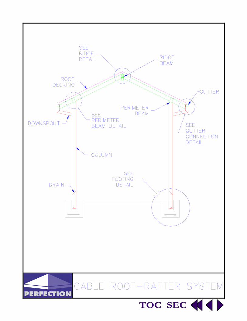
Gable Roof—Rafter System
System Specifications
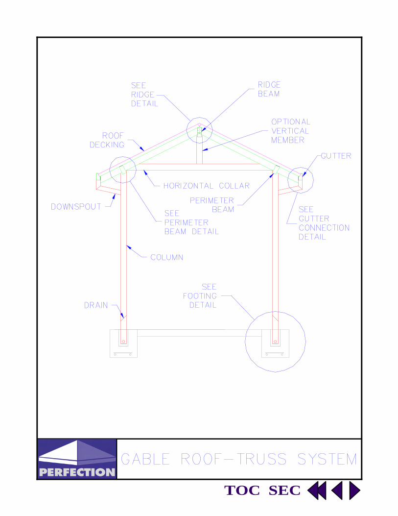
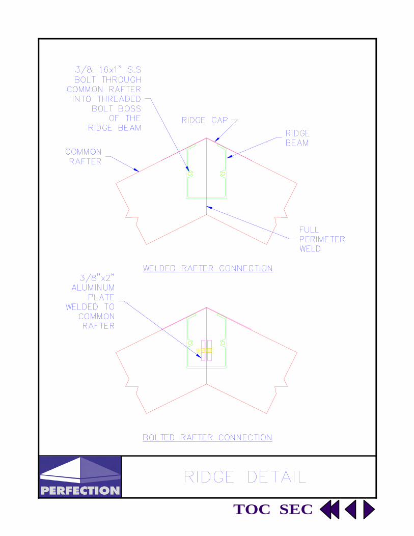
Gable Roof—Truss System Ridge Detail
Perimeter Beam Detail Gutter Downspout Detail
TOC SEC
TOC SEC
TOC SEC

TOC SEC

TOC SEC

TOC SEC
Sloped Roof SystemSloped Roof System
System Specifications
Upper Roof Detail
Lower Roof Detail
Free Standing
Wall Connection
Wall Mount Detail

TOC SEC

TOC SEC

TOC SEC

TOC SEC

TOC SEC

TOC SEC
Overhead Supported Overhead Supported Canopy SystemCanopy System
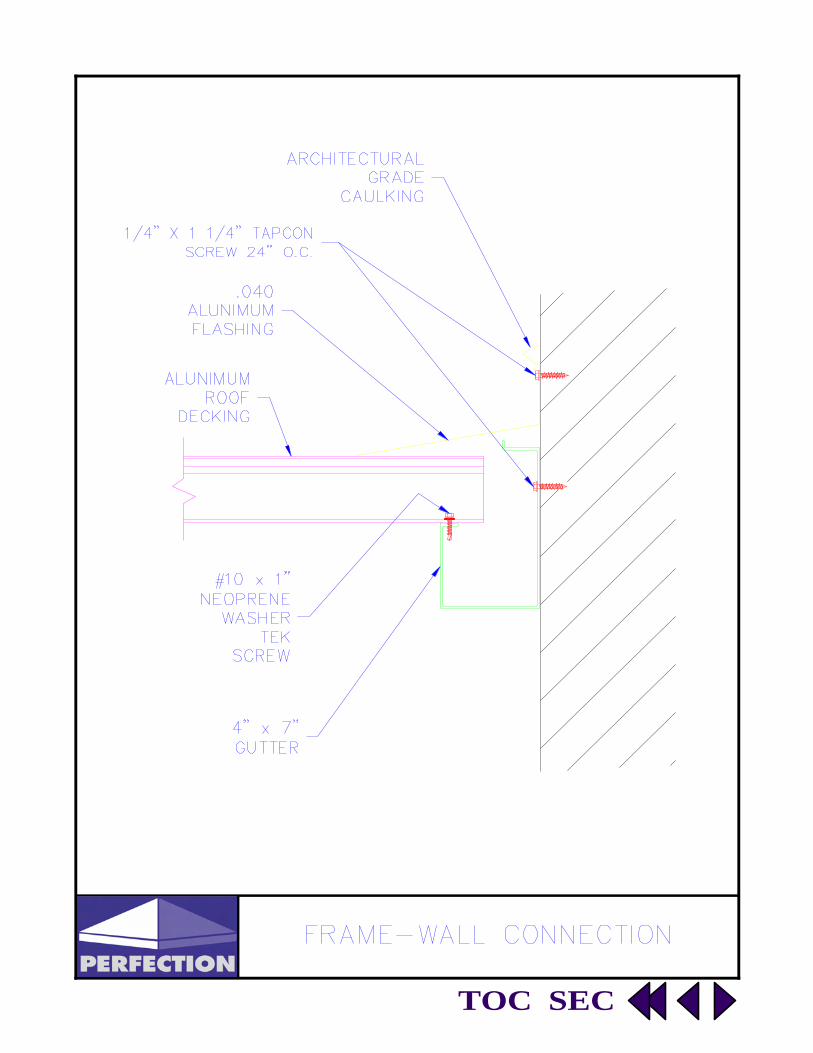
Frame-Wall Connection System Specifications
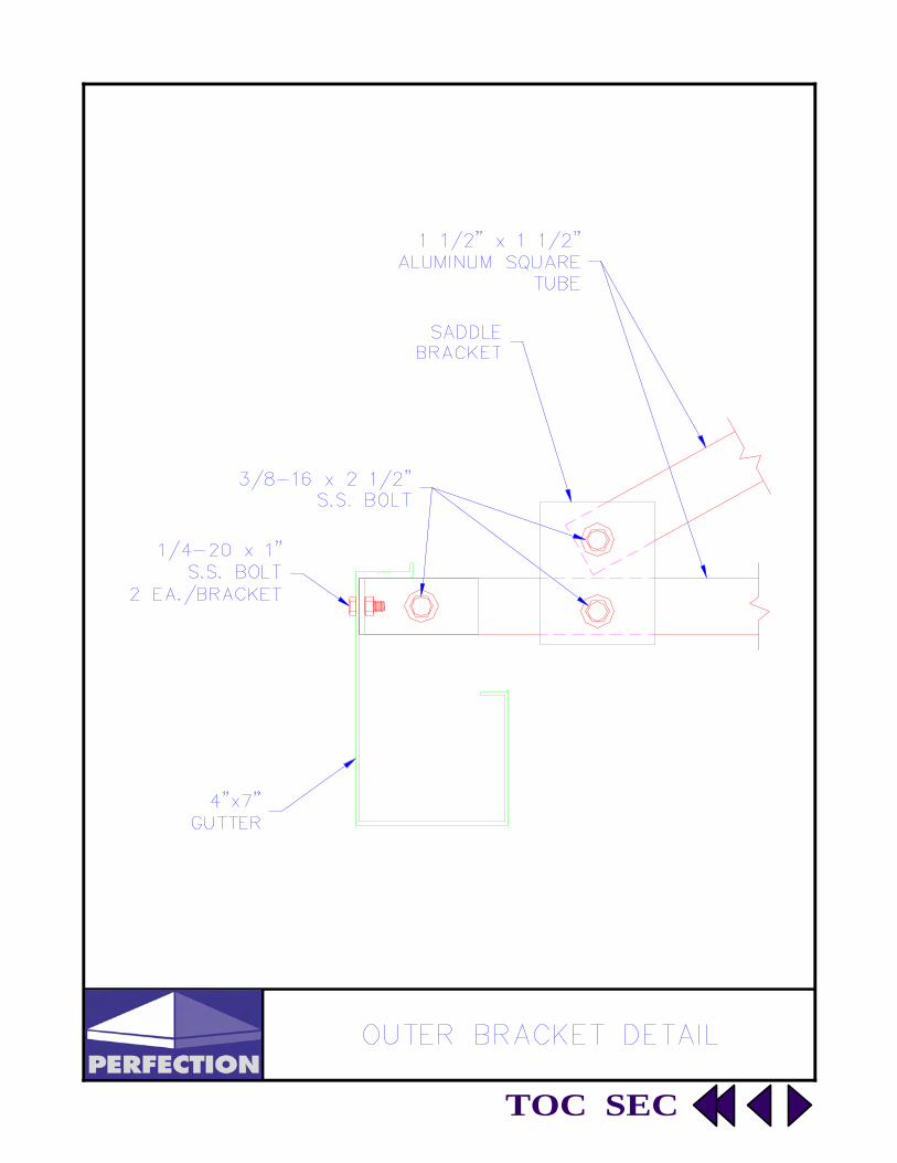
Outer Bracket Detail
Upper Bracket Detail
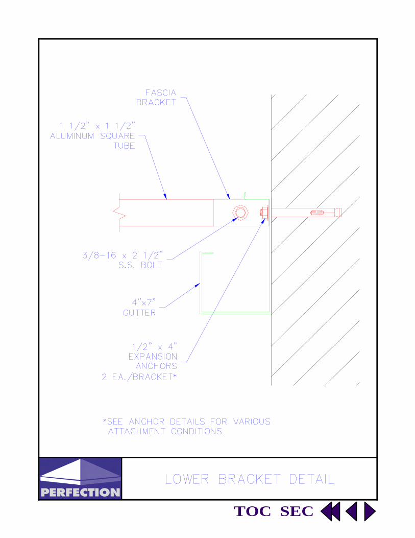
Lower Bracket Detail
Suspended Canopy

TOC SEC
TOC SEC

TOC SEC
TOC SEC
TOC SEC

TOC SEC
SpecialSpecial ApplicationsApplications
Pavilion
Vehicle Entrance Canopy
Picnic Pavilion

TOC SEC
Advent Lutheran School—Boca Raton, Florida

TOC SEC
Lakeland YMCA - Lakeland, Florida

TOC SEC
Rest Stop — Ocala , Florida

TOC SEC
SpecificationsSpecifications
Extruded Deck 2
System Specifications
Roll Formed Decking
Extruded Deck 1
Gutters & Facia
Columns
Beams

TOC SEC

TOC SEC

TOC SEC

TOC SEC

TOC SEC

TOC SEC

TOC SEC
Installation DetailsInstallation Details
Wedge Anchors - Concrete Wall
System Specifications
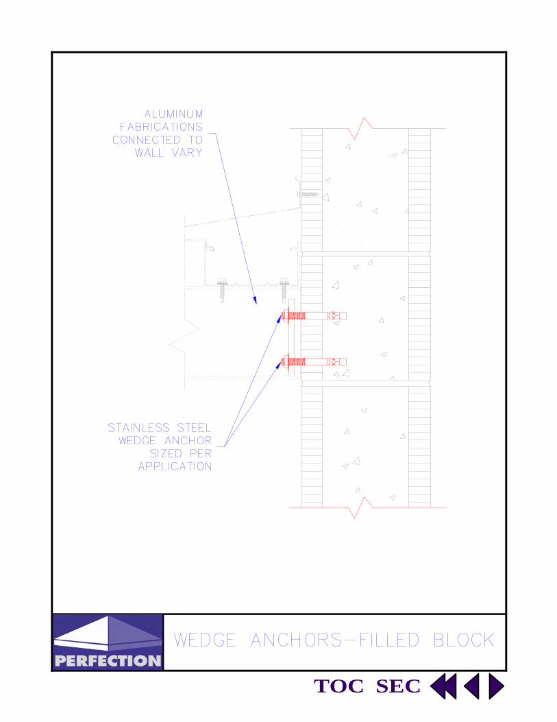
Wedge Anchors - Filled Block
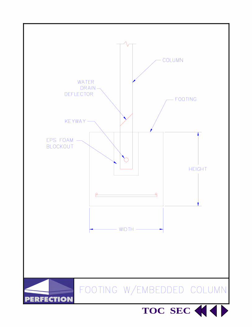
Concrete Footing - Basic Change of Direction
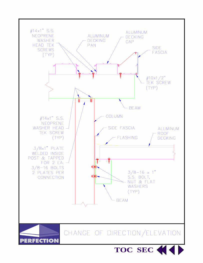
Change of Direction and Elevation
Change of Elevation Detail
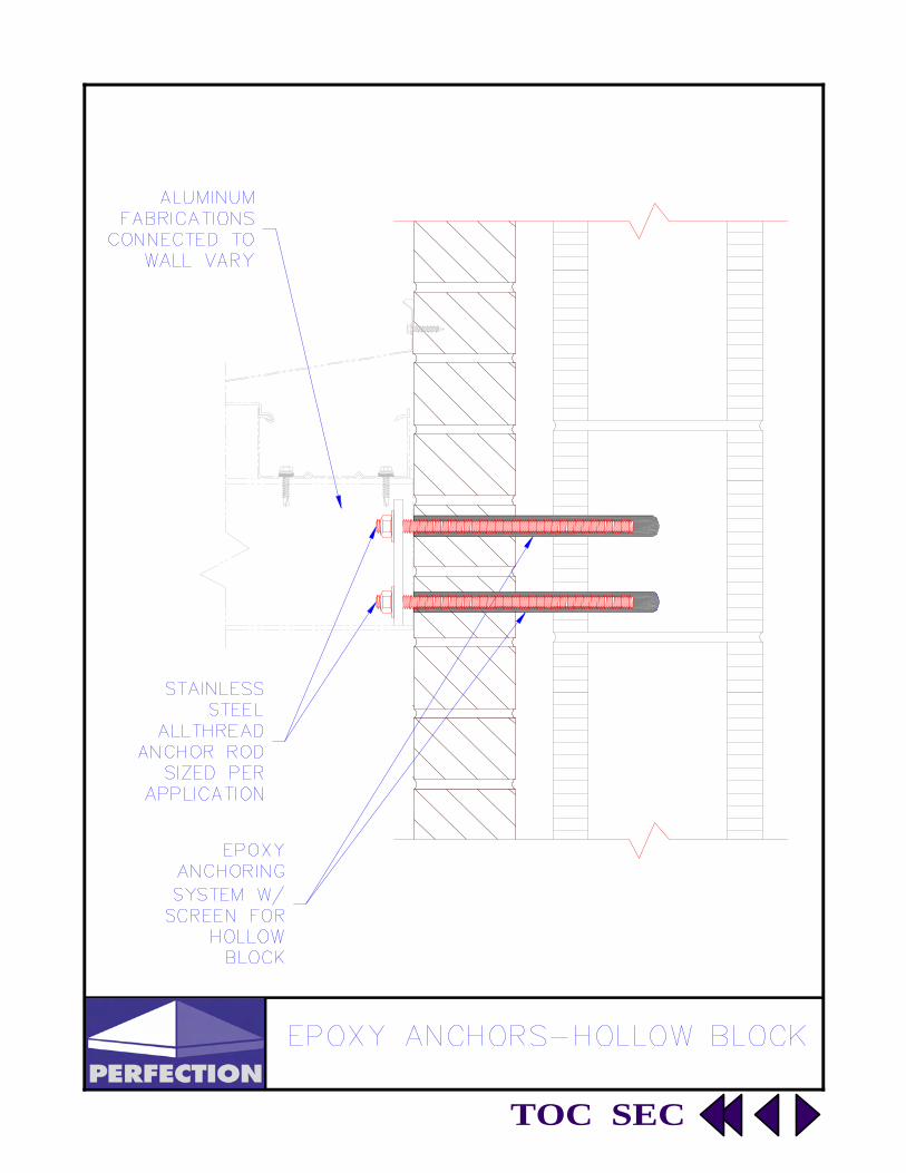
Epoxy Anchors - Hollow Block - Brick
Epoxy Anchors - Filled Block - Brick
T-Rain Cap Detail

TOC SEC
TOC SEC

TOC SEC
TOC SEC

TOC SEC
TOC SEC
TOC SEC

TOC SEC

TOC SEC

TOC SEC
FastenersFasteners
Standard Screws
System Specifications
Standard Bolts Standard Anchors

TOC SEC

TOC SEC

TOC SEC
TOC SEC
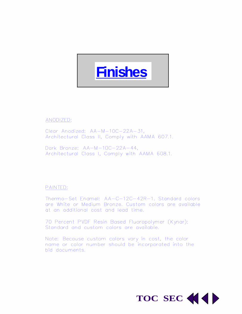
FinishesFinishes

TOC SEC
LightingLighting
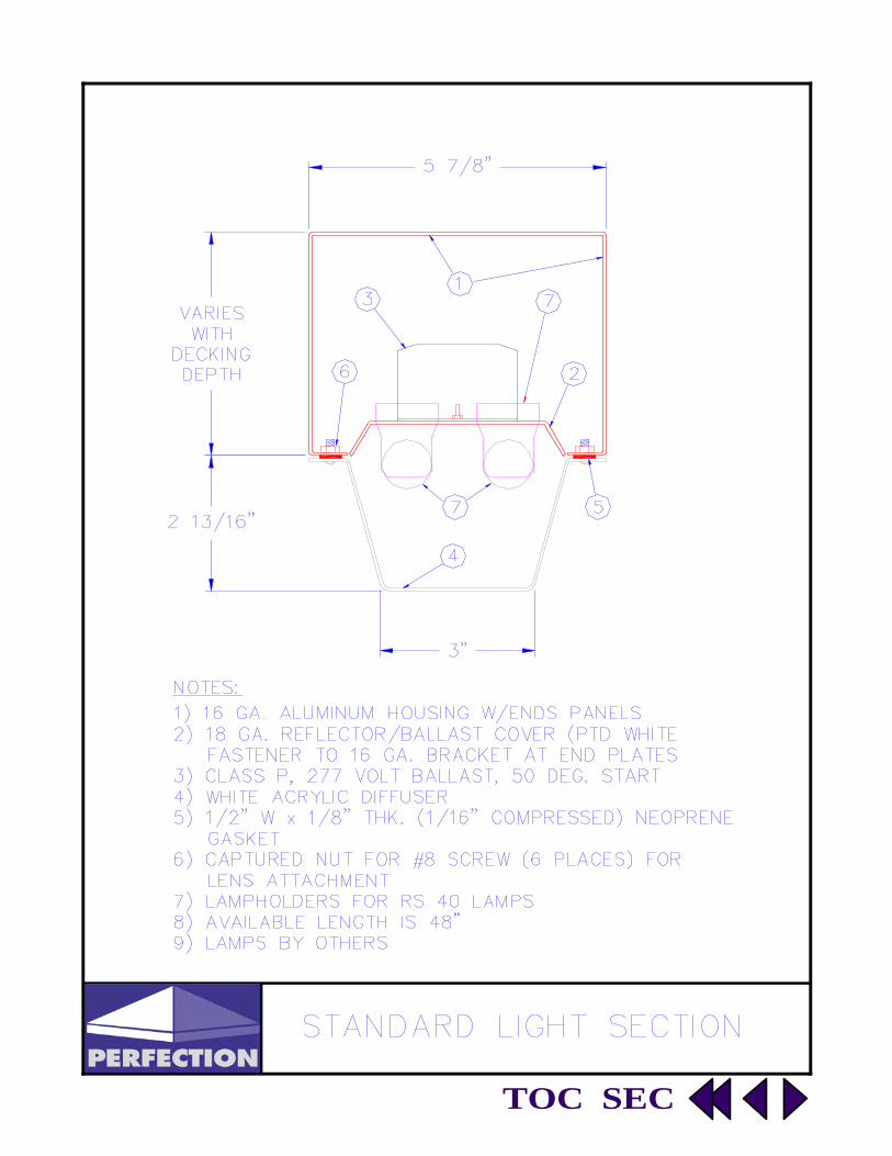
Standard Light Section
TOC SEC

58
SECTION 10530
PRE-ENGINEERED [WALKWAY COVERS] [CANOPIES] (Perfection Architectural Systems, Inc.)
GENERAL NOTES TO SPECIFIER: THIS SPECIFICATION SECTION HAS BEEN PREPARED TO ASSIST DESIGN PROFESSIONALS IN THE PREPARATION OF PROJECT OR OFFICE MASTER SPECIFICATIONS. IT FOLLOWS GUIDELINES ESTABLISHED BY THE CONSTRUCTION SPECIFICATIONS INSTITUTE, AND THEREFORE MAY BE USED WITH MOST MASTER SPECIFICATION SYSTEMS WITH MINOR EDITING. EDIT CAREFULLY TO SUIT PROJECT REQUIREMENTS. MODIFY AS NECESSARY AND DELETE ITMES THAT ARE NOT APPLICABLE. VERIFY THAT REFERENCED SECTION NUMBERS AND TITLES ARE CORRECT. (NUMBERS AND TITLES REFERENCED ARE BASED ON MASTERFORMAT, 1995 EDITION). THIS SECTION ASSUMES THE PROJECT MANUAL WILL CONTAIN COMPLETE DIVISION 1 DOCUMENTS IN-CLUDING SECTIONS 01330-SUBMITTAL PROCEDURES, 01620-PRODUCT OPTIONS, 01630-PRODUCT SUBSTI-TUTION PROCEDURES, 01660-PRODUCT STORAGE AND HANDLING REQUIREMENTS, 01770-CLOSEOUT PRO-CEDURES, AND 01780-CLOSEOUT SUBMITTALS. CLOSE COORDINATION WITH DIVISION 1 SECTIONS IS RE-QUIRED. IF THE PROJECT MANUAL DOES NOT CONTAIN THESE SECTIONS, ADDITIONAL INFORMATION SHOULD BE INCLUDED UNDER THE APPROPRIATE ARTICLES. THIS IS AN OPEN PROPRIETARY SPECIFICATION ALLOWING USERS THE OPTION OF APPROVING OTHER MANUFACTURERS WHICH COMPLY WITH THE CRITERIA SPECIFIED HEREIN. NOTES TO THE SPECIFIER ARE CONTAINED IN BOXES AND SHOULD BE DELETED FROM FINAL COPY. OPTIONAL ITEMS REQUIRING SELECTION BY THE SPECIFIER ARE ENCLOSED WITHIN BRACKETS, E.G: [35] [40] [45]. MAKE APPROPRIATE SELECTIONS AND DELETE OTHERS. ITEMS REQUIRING ADDITIONAL INFORRMATION ARE UNDERLINED BLANK SPACES, E.G: __________. OPTIONAL PARAGRAPHS REQUIRING SELECTION OF ONE OF THE OPTIONS ARE SEPARATED BY “OR” WITHIN A BOX, E.G
OPTIONAL FEATURES THAT MAY BE SELECTED OR DELETED AS DESIRED ARE SHOWN IN BOLD FACE TYPE.
OR
Click Here for an Editable Version of the
Specification 10530

TOC SEC
PART 1 GENERAL 1.1 SUMMARY
A. Section includes: Pre-engineered and pre-finished extruded aluminum [walkway
covers] [canopies]
B. Products Supplies But Not Installed Under This Section: Foam block-outs for col-umn foundations.
C. Related Sections: 1. 03100-Concrete Forms and Accessories 2. 03300-Cast-in-Place Concrete
1.2 SYSTEM DESCRIPTION VERIFY SPACING AND CONFIGURATION OF STRUCTURAL MEMBERS DOES NOT EXCEED MANUFACTURER’S DESIGN LOAD LIMITATIONS.
A. Design Requirements:
VERIFY SIZE/CONFIGURATION OF ONE PIECE RIGID BENTS, IF SPECIFIED BELOW, DOES NOT EXCEED MANUFACTURER’S SHIPPING LIMITATIONS.
1. Columns, beams, deck and trim shall be aluminum extrusions. Structural framing shall consist of [heli-arc welded, one-piece rigid bents] [and] [bolt connected members] with interlocking deck sections secured by screws. Canopy Shall be self-draining from deck through bents to discharge point [at ground level] [as shown on Drawings].
2. Building Code: [SBCCI, Standard Building Code] [International Building Code], ______ Edition.
3. Design Loads: a. Comply with Building Code for site location. b. Collateral Loads: Additional loads imposed by other materials or systems
identified in contract documents. 4. Structural Design: Prepare complete structural design calculations for can-
opy members including footings.
OR 4. Strutural Design: Prepare complete structural design calculations for canopy members except footings. Provide reactions as required for footing design by the Engineer of Record.
1.3 SUBMITTALS
A. Reference Section 01330-Submittal Procedures; submit following items:
1. Product data. 2. Shop Drawings: Layout and erection drawings showing roof framing, deck
panels, cross sections and trim details clearly indicating proper assembly. 3. Samples: Color selection samples consisting of actual coating material or
anodizing process on aluminum extrusions.

TOC SEC
4. Quality Assurance/Control Submittals: a. Qualifications: Letter certifying manufacturer’s required qualifications. b. Structural Design Calculations. c. Manufacturer’s Installation Instructions.
1.1 QUALITY ASSURANCE
A. Overall Standards: Structural engineering design documents shall be stamped by a structural engineer registered to practice in the state of [Florida] [______].
A. Qualifications:
1. Manufacturer Qualifications: Minimum five years experience in producing covers/canopies with welded bents and of the type specified.
2. Installer Qualifications: Minimum two years experience in erecting covers/canopies of the type specified.
1.2 DELIVERY STORAGE AND HANDLING
A. Reference Section 01660-Product Storage and Handling Requirements.
A. Follow manufacturer’s instructions. PART 2 PRODUCTS
1.1 MANUFACTURERS
A. Manufacturer: Perfection Architectural Systems, Inc. 4460 North Goldenrod Road, Bldg. 104 Winter Park, FL 32792 Tel: (800) 238-7207 Fax: (407) 671-8252 INSERT NAME, ADDRESS AND PHONE NUMBERS OF LOCAL REPRESENTATIVE BELOW.
1. Representative:
B. Substitutions: Reference Section 01630-Product Substitution Procedures. 1.2 MATERIALS
A. Aluminum Extrusions: 6063 alloy, T-6 temper.
B. Grout: 1 part portland cement, 3 parts masonry sand; 2,000 psi (13.8 MPa) compressive strength.
C. Foam Block-Outs: Rigid foam blocks sized as required for column embedment depth and shape.
1.3 COMPONENTS
A. Columns: 1. Radius-cornered aluminum tubular extrusions [of size shown on Drawings] [as required by structural engineering design].

TOC SEC
3. Grout Key: Provide two 1 ½ inch (38 mm) diameter holes in column base, one each in opposite sides.
4. Provide clear acrylic protection coat on surfaces in contact with grout.
B. Beams: Open top aluminum tubular extrusions [of size shown on Drawings] [as re-quired by structural engineering design].
C. Deck: Rigid-Roll-Lock extruded aluminum, self-flashing, interlocking sections [of size and profile shown on Drawings] [as required by structural engineering design].
1. Provide welded endplate water dams where sections terminate at other than drain-age channels.
D. Fascia: Provide manufacturer’s standard extruded aluminum fascia [and gutter] sections as shown on Drawings and as required to complete the installation resulting in a neat finished appearance.
E. Flashing: Aluminum sheet, thickness as recommended by manufacturer for specific condition.
2.4 ACCESSORIES
A. Fasteners: 1. Deck Screws: No. 14 x 1 inch (25 mm), self tapping, Type 18-8 stainless steel with
neoprene washer. 2. Trim Screws: No. 10 x ½ inch (13 mm), self tapping, Type 18-8 stainless steel.
OR
3. Trim Rivets: Aluminum rivets, size as recommended by manufacturer for specific condition.
4. Other Fasteners: Type 18-8 stainless steel, fastener type as recommended by manufacturer for specific condition.
2.5 FABRICATION
A. Shop Assembly: Fabricate cross beams and columns into one piece rigid bents with
corners mitered and heli-arc welded to the extent that completed bents can be shipped on local, state and federal highways without special permit. Provide bolted connections for bents required to be shipped unassembled.
OR
A. Shop Assembly: Fabricate cross beams and columns for field assembled bolted con-nections.
2.6 FINISH SELECT ONE OF THE FOUR FOLLOWING FINISHES FOR BENTS; ONE FOR THE DECK AND ONE FOR THE FASCIA/GUTTER; DELETE THE REMAINING THREE. DIFFERENT FINISHES CAN BE SELECTED FOR EACH ITEM.
TOC SEC
A. Bents: 1. Clear Anodized: AA-M-10C-22A-31, Architectural Class II, comply with AAMA
607.1. 2. Bronze Anodized: AA-M-10C-22A-44, Architectural Class I, comply with AAMA
608.1. 3. Thermo-Set Enamel: AA-C-12C-42R-1, [color as selected by Architect from manu-
facturer’s standard color range] [custom color as selected by Architect], comply with AAMA 603.
4. 70 percent PVDF resin based fluoropolymer: AA-C-12C-42R-1, [2] [3] coat appli-cation, custom color as selected by Architect, comply with AAMA 605.
B. Deck:
1. Clear Anodized: AA-M-10C-22A-31, Architectural Class II, comply with AAMA 607.1.
2. Bronze Anodized: AA-M-10C-22A-44, Architectural Class I, comply with AAMA 608.1.
3. Thermo-Set Enamel: AA-C-12C-42R-1, [color as selected by Architect from manu-facturer’s standard color range] [custom color as selected by Architect], comply with AAMA 603.
4. 70 percent PVDF resin based fluoropolymer: AA-C-12C-42R-1, [2] [3] coat appli-cation, custom color as selected by Architect, comply with AAMA 605.
C. Fascia/Gutter:
1. Clear Anodized: AA-M-10C-22A-31, Architectural Class II, comply with AAMA 607.1.
2. Bronze Anodized: AA-M-10C-22A-44, Architectural Class I, comply with AAMA 608.1.
3. Thermo-Set Enamel: AA-C-12C-42R-1, [color as selected by Architect from manu-facturer’s standard color range] [custom color as selected by Architect], comply with AAMA 603.
4. 70 percent PVDF resin based fluropolymer: AA-C-12C-42R-1, [2] [3] coat applica-tion , custom color as selected by Architect, comply with AAMA 605.
PART 3 EXECUTION
3.1 EXAMINATION
A. Examine footings in which bents will be set [and building surfaces to which canopy will connect]. Verify footing locations and elevations comply with shop drawings.
B. Coordinate with responsible entity to perform corrective work on unsatisfactory foot-ings or surfaces.
C. Commencement of work by installer is acceptance of existing conditions. 3.2 ERECTION
A. Erect canopy in accordance with manufacturer’s installation instructions.
B. Set bents plumb, straight and true to line, adequately braced to maintain position until grout has cured.
3.3 CLEANING A. Clean surfaces soiled by work as recommended by manufacturer.

TOC SEC
B. Remove surplus materials and debris from the site. 3.4 PROTECTION A. Protect finished aluminum surfaces from damage due to subsequent operations
through [Substantial Completion] [final acceptance by the Owner] B. END OF SECTION

SunshadesSunshades
Horizontal Overhead Supported
Sloped Bottom Supported
Sunshade Applications
Sunshade Specification


SunshadeSunshade ApplicationsApplications
Horizontal
Sloped
Variations

Freedom Elementary School Bradenton, Florida

Freedom High School Orlando, Florida

Freedom High School Orlando, Florida

SECTION 10705 - EXTERIOR SUN CONTROL DEVICES PART 1 - GENERAL 1.1 RELATED DOCUMENTS A. Drawings and general provisions of the Contract, including General and Supplementary Conditions and Division 1 Specification Sections, apply to this Section. 1.2 SUMMARY A. This Section includes the following: 1. Horizontal and or inclined fixed, extruded-aluminum sun control assemblies. B. Related Sections include the following: 1. Division 5 Section "Structural Steel” for supporting structure. 1.3 PERFORMANCE REQUIREMENTS
A. Structural Performance: Provide exterior sun control assemblies capable of withstanding the effects of loads and stresses from dead loads, live loads, snow loads, snow drift loads, wind loads, and normal thermal movement without evidencing permanent deformation of assembly or components including blades, frames, and supports; noise or metal fatigue caused by blade rat-tle or flutter; or permanent damage to fasteners and anchors. Assemblies shall comply with state and local codes.
1. Dead Load: As required by applicable building code. 2. Live Load: As required by applicable building code. 3. Snow Load: As required by applicable building code. 4. Snow Drift Load: As required by applicable building code.
5. Wind Load: Uniform pressure (velocity pressure) of (Insert Design Criteria) lb./sq. ft. (Insert Design Criteria Pa), acting inward or outward.
6. Thermal Movements: Provide assemblies that allow for thermal movements result ing from the following maximum change (range) in ambient and surface tempera tures by preventing buckling, opening of joints, overstressing of components, and other detrimental effects:
a. Temperature Change (Range): 120 deg F (67 deg C), ambient; 180 deg F
(100 deg C), material surfaces. 1.4 SUBMITTALS
A. Product Data: Manufacturer’s technical and descriptive data on sun control components and assemblies.
B. Shop Drawings: For exterior sun control assemblies and accessories. Include plans; eleva-
tions; sections; and details showing profiles, angles, and spacing of blades, frames and sup-ports. Show unit dimensions related to supporting and adjoining structures and construction. Indicate anchorage details and locations.
C. Structural Calculations: Submit a comprehensive analysis of design loads, including dead
loads, live loads, snow loads, snow drift loads, wind loads and thermal movement. Design cal-culations shall identify the moment and shear forces transferred to the structure or supports through the installation connections.
D Structural Calculations shall be stamped and signed by a professional engineer registered in
jurisdiction where Project is located.
Click Here for an Editable
Version of the Specification 10705

E. Samples for Initial Selection: Manufacturer's color charts showing the full range of colors available for units with factory-applied color finishes.
F. Samples for Verification: Of each type of metal finish required, prepared on samples of same thick-
ness and material indicated for final work. Where finishes involve normal color and texture varia-tions, include sample sets showing the full range of variations expected.
G. Qualification Data: For firms and persons specified in "Quality Assurance" Article to demonstrate
their capabilities and experience. Include lists of completed projects with project names and ad-dresses, names and addresses of architects and owners, and other information specified.
1.5 QUALITY ASSURANCE
A. Professional Engineer Qualifications: A professional engineer who is legally qualified to practice in juris-diction where Project is located and who is experienced in providing engineering services of kind indi-cated. Engineering services are defined as those performed for installations of sun controls that are similar to those indicated for this Project in material, design, and intent.
1. Welding Standards: As follows: a. Comply with AWS D1.2, "Structural Welding Code--Aluminum." b. Comply with AWS D1.3, "Structural Welding Code--Sheet Steel."
c. Certify that each welder has satisfactorily passed AWS qualification tests for welding processes involved and, if pertinent, has undergone recertification. SMACNA Standard: Comply with SMACNA's "Architectural Sheet Metal Manual" recommendations for fabrication, construction details, and installation procedures.
1.6 PROJECT CONDITIONS
A. Field Measurements: Verify actual supporting and adjoining construction by field measurements be-fore fabrication; and indicate recorded measurements on final Shop Drawings. Coordinate construc-tion to ensure that sun control assemblies fit properly to supporting and adjoining construction and coordinate schedule with construction progress to avoid delaying the work.
1. Established Dimensions: Where field measurements cannot be made without delaying the work,
verify dimensions and proceed with fabricating of sun control assemblies without field measure-ments. Coordinate construction to ensure that sun control assemblies correspond to estab-lished dimensions.
PART 2 - PRODUCTS 2.1 MANUFACTURERS
A. Manufacturers:
1. Perfection Architectural Systems, Inc. 2310 Mercator Drive
Orlando, FL 32807 800-238-7207 Fax 407-671-8252 www.perfectionarch.com 2.2 MATERIALS A. Aluminum Extrusions: ASTM B 221 (ASTM B 221M), alloy 6063-T5 or T-52.
B. Aluminum Sheet: ASTM B 209 (ASTM B 209M), alloy 3003 or 5005 with temper as required for forming, or as otherwise recommended by metal producer for required finish.

C. Aluminum Castings: ASTM B 26/B 26M, alloy 319.
D. Stainless-Steel Sheet: ASTM A 666, Type 302 or 304.
E. Fasteners: Of same basic metal and alloy as fastened metal or 300 series stainless steel, unless
otherwise indicated. Do not use metals that are incompatible with joined materials. 1. Use types and sizes to suit unit installation conditions.
2. Use Phillips flat-head screws for exposed fasteners, unless otherwise indicated.
F. Anchors and Inserts: Of type, size, and material required for loading and installation indicated. Use non-ferrous metal or hot-dip galvanized anchors and inserts for exterior installations and elsewhere as needed for corrosion resistance. Use toothed steel or expansion bolt devices for drilled-in-place an-chors.
G. Bituminous Paint: Cold-applied asphalt mastic complying with SSPC-Paint 12 but containing no asbes-
tos fibers, or cold-applied asphalt emulsion complying with ASTM D 1187. 2.3 FABRICATION, GENERAL
A. Assemble sun control assemblies in factory to minimize field splicing and assembly. Disassemble units as necessary for shipping and handling limitations. Clearly mark units for reassembly and coordinated installation.
B. Sun control assemblies shall be assembled entirely by mechanical fasteners or welding. Components
shall be joined with a minimum of two fillet welds each one-inch (25.4 mm) long produced with the Pulsed Gas Metal Arc Welding (GMAW/MIG) process with minimum 0.125” (3.18 mm) throat.
C. Maintain equal sun control blade spacing, including separation between blades and frames to produce
uniform appearance.
D. Include supports, anchorages, and accessories required for complete assembly.
E. Join frame members to one another and to fixed sun control blades with mechanical joints concealed from view, unless size of sun control assembly makes concealed, bolted connections between frame members necessary.
2.4 HORIZONTAL and/or INCLINED FIXED, EXTRUDED-ALUMINUM SUN CONTROLS
A. Horizontal and/or inclined, fixed, extruded-aluminum sun control assemblies complying with the follow-ing:
1. Blade: Specify blade type, material and thickness, as indicated. 2. Outrigger: Specify outrigger type, material and thickness, as indicated. 3. Fascia: Specify fascia type, material and thickness, as indicated. 2.5 FINISHES, GENERAL A. Comply with NAAMM's "Metal Finishes Manual for Architectural and Metal Products" for recommendations for applying and designating finishes. B. Finish sun controls after assembly. 2.6 ALUMINUM FINISHES
1. Clear Anodized: AA-M-10C-22A-31, Architectural Class II, comply with AAMA 607.1.
2. Bronze Anodized: AA-M-10C-22A-44, Architectural Class I, comply with AAMA 608.1.

3. Thermo-Set Enamel: AA-C-12C-42R-1, comply with AAMA 603. a. Color: As selected by architect from manufacturer's standard color
range. ** NOTE TO SPECIFIER ** Delete subparagraph above or below as required for the project.
b. Color: Custom color as selected by architect. 4. Fluoropolymer Coating: 70 percent PVDF resin based fluoropolymer,
AA-C-12C-42R-1, custom color as selected by architect, comply with AAMA 605. a. Two coat application.
** NOTE TO SPECIFIER ** Delete subparagraph above or below as required for the project. b. Three coat application.
PART 3 - EXECUTION 3.1 PREPARATION
A. Coordinate Installation Drawings, diagrams, templates, instructions, and directions for anchorages that are to be embedded in concrete or masonry construction. Coordinate delivery of such items to Project site.
3.2 INSTALLATION
A. Locate and place sun control assemblies level, plumb, and at indicated alignment with adjacent work.
B. Use concealed anchorages where possible. Provide stainless steel/neoprene washers fitted to screws where required to protect metal surfaces and to make a weather tight connection.
C. Form closely fitted joints with exposed connections accurately located and secured.
D. Repair finishes damaged by cutting, welding, soldering, and grinding. Restore finishes so no evidence remains of corrective work. Return items that cannot be refinished in the field to the factory, make re-quired alterations, and refinish entire unit or provide new units.
a. Protect galvanized and nonferrous-metal surfaces from corrosion or galvanic action by applying
a heavy coating of bituminous paint on surfaces that will be in contact with concrete, masonry, or dissimilar metals.
3.3 CLEANING AND PROTECTING
A. Clean exposed surfaces of sun control devices that are not protected by temporary covering to remove fingerprints and soil during construction period.
B. Clean exposed surfaces with water and a mild soap or detergent not harmful to finishes. Thoroughly
rinse surfaces and dry.
C. Protect sun control assemblies from damage during construction. Use temporary protective coverings where needed and approved by the sun control manufacturer.
D. Clean and touch up minor abrasions in finishes with air-dried coating that matches color and gloss of, and is compatible with, factory-applied finish coating.
END OF SECTION