efore opus power system - innovative energiesinnovative.co.nz/uploads/pdf/opus_usermanual.pdf ·...
TRANSCRIPT

Efore OPUSPower SystemUser’s manual

Efore OPUS Power System User Manual
2
Efore Plc. makes no representations or warranties with respect to the contents or use of this documentation and speci cally disclaims any express or implied warranties of merchantability or tness for any particular purpose. Further, Efore Plc reserves the right to revise this publication and to make changes to its content, at any time, without obligation to notify any person other or entity of such revisions.
Further, Efore Plc makes no representations or warranties with respect to any software, also speci cally disclaiming any express or implied warranties of merchantability or tness for any particular purpose. In addition, Efore Plc reserves the right to make changes to any and all parts of Efore software, at any time, without any obligation to notify any person or other entity of such changes.
All copyrights reserved. No part of this publication may be reproduced, photocopied, stored in a retrieval system, or transmitted without the express written consent of the publisher.
This document contains a description of the product and as detailed instructions for its use as possible. However, the possibility of errors cannot be ruled out entirely.
In the event of ambiguities or contradiction between different language versions, the Eng-lish version of this document shall be considered authoritative.
Efore OPUS Power System User Manual
3
TABLE OF CONTENTS
1...... CONVENTIONS USED IN THIS DOCUMENT ................. 8
1.1. ...Acronyms and Terms Used in this Document ...................... 81.2. ...Symbols Used in this Document .................................... 91.3. ...Special Text Styles Used in this Document .......................... 91.4. ...Trademarks Mentioned in This Document ........................... 91.5. ...Revision History of the User’s Manual DEV_06365 ............. 91.6. ...User Manual and Firmware Revision Compatibility ........... 10
2...... INTRODUCTION .............................................................11
2.1. ...System Modules................................................................. 112.2. ...Controller Modules and Busses ......................................... 122.3. ...Voltage Versions ................................................................ 122.4. ...Recti ers ............................................................................ 122.5. ... Inverter and Bypass Modules............................................. 132.6. ...Batteries ............................................................................. 13
2.6.1. .. Battery Con guration ............................................. 142.7. ...Modbus TCP ...................................................................... 15
2.7.1. .. Memory Areas ........................................................ 152.7.2. .. Operation Modes ................................................... 162.7.3. .. Measurements ....................................................... 172.7.4. .. Alarms .................................................................... 17
2.8. ...EchoAgent.......................................................................... 21
3...... PRINCIPLES OF OPERATION ......................................22
3.1. ...Parameter System ............................................................. 223.2. ...Busses, Modules, Ports, and Devices................................ 23
3.2.1. .. Busses and Modules ............................................. 233.2.2. .. Ports ...................................................................... 243.2.3. .. Devices .................................................................. 253.2.4. .. Inventory Limit ....................................................... 25
3.3. ...Charge Modes.................................................................... 263.3.1. .. Float Charge .......................................................... 263.3.2. .. Boost Charge ......................................................... 263.3.3. .. Battery Charge Current Limiting ............................ 273.3.4. .. Battery Tests .......................................................... 283.3.5. .. Temperature Compensation .................................. 293.3.6. .. Recti er Default Voltage ........................................ 29
3.4. ...Mains Fault......................................................................... 303.5. ...Low Voltage Disconnect (LVD) ........................................... 303.6. ...Alarms ................................................................................ 31
3.6.1. .. External Alarms ...................................................... 323.7. ...LED Indications .................................................................. 32
3.7.1. .. Local Display Module ............................................. 323.7.2. .. Recti er .................................................................. 333.7.3. .. LVD Module ........................................................... 333.7.4. .. BM Module ............................................................. 333.7.5. .. SAM Module .......................................................... 33
Efore OPUS Power System User Manual
4
4...... LOCAL USER INTERFACE .............................................34
4.1. ...General .............................................................................. 344.2. ...The First Start-up ............................................................... 35
4.2.1. .. Base Parameters Dialog ........................................ 354.2.2. .. New Modules Dialog .............................................. 354.2.3. .. Uncon gured Modules Dialog ................................ 35
4.3. ...Main Display....................................................................... 364.4. ...Main Menu ......................................................................... 374.5. ...Measurements ................................................................... 37
4.5.1. .. System Measurements ......................................... 374.5.2. .. Battery Block Measurements ................................. 384.5.3. .. Battery Current Measurements .............................. 394.5.4. .. Load Current Measurements ................................. 394.5.5. .. Recti er Measurements ......................................... 394.5.6. .. Inverter Measurements .......................................... 414.5.7. .. Bypass Measurements .......................................... 42
4.6. ...Parameters ........................................................................ 424.6.1. .. Parameter Page .................................................... 434.6.2. .. Device List Parameters .......................................... 43
4.7. ... Inventory ........................................................................... 444.7.1. .. Locating Modules ................................................... 454.7.2. .. Module Information ............................................... 454.7.3. .. Changing Node Index ............................................ 454.7.4. .. Locating Devices ................................................... 464.7.5. .. Device Information ................................................. 474.7.6. .. Changing Device Usage ........................................ 484.7.7. .. Changing Device Index .......................................... 484.7.8. .. Changing Device Attributes ................................... 49
4.8. ...Alarms ................................................................................ 504.8.1. .. Alarm Logs ............................................................. 504.8.2. .. Alarm Information and Acknowledgement ............. 504.8.3. .. Batch Actions on Alarm Masses ............................ 514.8.4. .. Setting Alarm Parameters ..................................... 514.8.5. .. Con guring Alarm Relays ...................................... 52
4.9. ...Actions ............................................................................... 524.9.1. .. Device Tests ........................................................... 524.9.2. .. Manual Boost Charging ......................................... 524.9.3. .. Manual Battery Tests ............................................ 524.9.4. .. Factory Parameters ............................................... 524.9.5. .. Restarting Controller .............................................. 534.9.6. .. Reset Battery Discharge ....................................... 534.9.7. .. Clear All Data ........................................................ 53
4.10. .Common Tasks .................................................................. 544.10.1. Setting the Low Voltage Alarm Limit ...................... 544.10.2. Setting LVD Pickup and Disconnect Parameters ... 544.10.3. Setting the Battery Charge Current Limit ............... 544.10.4. Changing Start Times of Periodic Tasks ................ 554.10.5. Setting the Earth Fault Detection Threshold .......... 554.10.6. Removing Obsolete Modules from Inventory ......... 56
4.11. ..Menu Structure .................................................................. 56
Efore OPUS Power System User Manual
5
5...... REMOTE INTERFACES ................................................. 57
5.1. ... Introduction ........................................................................575.2. ...RS-232 Port ....................................................................... 575.3. ...Ethernet port ......................................................................58
5.3.1. .. Indirect Connection ..............................................595.3.2. .. Direct Connection ..................................................59
5.4. ...TCP/IP Con guration Utility ...............................................605.4.1. .. Locating the Systems in the Network ....................60
5.5. ...Web Interface .....................................................................615.5.1. .. Introduction ............................................................ 615.5.2. .. Login ......................................................................615.5.3. .. Usage ...................................................................625.5.4. .. Structure ................................................................62
5.6. ...Terminal Interface...............................................................635.6.1. .. Telnet .....................................................................635.6.2. .. SSH ....................................................................... 635.6.3. .. RS-232 ...................................................................635.6.4. .. Login ......................................................................635.6.5. .. Usage .................................................................... 645.6.6. .. Uploading/Downloading Files ...............................645.6.7. .. Changing Parameters ........................................... 65
5.7. ...User Levels ........................................................................655.8. ...SNMP/SMTP Alarm Noti cation .........................................67
5.8.1. .. SNMP ..................................................................... 675.8.2. .. SMTP ............................................................67
5.9. ...Administration ....................................................................685.9.1. .. Changing the Date/Time ........................................685.9.2. .. Programmable Con guration Logic .......................685.9.3. .. Administrative Actions ...........................................70
5.10. .Downloading and Uploading System Inventory Database . 715.11. ..Downloading and Uploading System Parameters.............. 715.12. .System Logs and Data Exporting.......................................725.13. .Firmware Update................................................................ 72
5.13.1. Update Methods ....................................................735.13.2. Performing Firmware Update .................................735.13.3. Module-Speci c Update Notes .............................745.13.4. Firmware Redundancy ...........................................75
6...... SYSTEM MAINTENANCE .............................................. 76
6.1. ...General .............................................................................. 766.2. ...Removing Recti er/Inverter/Bypass Module ......................766.3. ...Adding a New Recti er/Inverter/Bypass Module ................766.4. ...Replacing the System Controller Module ...........................766.5. ...Adding or Removing Other System Modules .....................776.6. ...Calibrating the Current Shunt Offset .................................. 78
7...... PARAMETERS ............................................................... 79
7.1. ...Parameter and Alarm Parameter Groups...........................797.2. ...Parameter Descriptions...................................................... 79
7.2.1. .. System Parameters ............................................... 807.2.2. .. Battery Parameters ..............................................807.2.3. .. Communication Parameters ................................80
Efore OPUS Power System User Manual
6
7.2.4. .. Charge Parameters ............................................. 817.2.5. .. Battery Tests ........................................................ 817.2.6. .. LVD Defaults ........................................................ 837.2.7. .. Inverter Parameters ............................................. 837.2.8. .. Alarm Parameters ................................................ 83
8...... DEVICE PARAMETERS ..................................................89
8.1. ...Recti ers ............................................................................ 898.2. ...EIM Inverters ...................................................................... 898.3. ...EBPU Bypass Modules ...................................................... 898.4. ...Current Measurement ........................................................ 908.5. ...Battery Voltage Measurement ............................................ 908.6. ...Block Voltage Measurement .............................................. 908.7. ...Temperature Measurement ................................................ 908.8. ...Alarm Relays ...................................................................... 918.9. ...Alarm Inputs ....................................................................... 918.10. .Earth Fault Alarm ............................................................... 918.11. .. Low Voltage Disconnect ............................................... 92
9...... ALARMS ..........................................................................93
9.1. ...System Over Temperature ................................................. 939.2. ...Low System Voltage........................................................... 939.3. ...High System Voltage .......................................................... 939.4. ...Mains Fault......................................................................... 939.5. ...Charge Voltage Deviation .................................................. 939.6. ...Bypass Mains Fault ............................................................ 949.7. ...Phase Fault ........................................................................ 949.8. ... Inverter System Fault ......................................................... 949.9. ...Recti ers Overload............................................................. 949.10. . Inverters Overload.............................................................. 949.11. ..Bus Fault ............................................................................ 959.12. . Inventory Full...................................................................... 959.13. .Earth Fault.......................................................................... 959.14. .Boost Charge Active........................................................... 959.15. .Con guration Con ict ......................................................... 959.16. .Recti er Fault ..................................................................... 969.17. .Recti er Over Voltage ........................................................ 969.18. .Recti er Over Temperature ................................................ 969.19. .Recti er Mains Fault .......................................................... 969.20. .Recti er Wrong Voltage Version ........................................ 969.21. .Communication Error ......................................................... 969.22. .Module Fault ...................................................................... 979.23. . Inverter Fault ...................................................................... 979.24. .Bypass Fault ...................................................................... 979.25. .NvRam Fault ...................................................................... 979.26. .Con g Fault ........................................................................ 979.27. .Bad Firmware ..................................................................... 979.28. .Automatic Boost Charge Fault ........................................... 989.29. .Battery Test Fault ............................................................... 989.30. .Battery Block Low Voltage ................................................. 989.31. .Battery Block High Voltage................................................. 989.32. .Battery Over Temperature .................................................. 989.33. .Battery String Asymmetry................................................... 99
Efore OPUS Power System User Manual
7
9.34. .Load LVD Disconnect Warning .......................................... 999.35. .Load LVD Disconnect Imminent ......................................... 999.36. .Battery LVD Disconnect Warning ....................................... 999.37. .Battery LVD Disconnect Imminent ..................................... 999.38. .Contactor Fault..................................................................1009.39. .Battery Fuse Fault .............................................................1009.40. .Load Fuse Fault ................................................................1009.41. .Current Shunt Fault ...........................................................1009.42. .Battery Temperature Sensor Fault ....................................1009.43. .No Battery Temperature Sensor ........................................1009.44. .No System Temperature Sensor .......................................1019.45. .Ext. Alarm Group 1 ............................................................1019.46. .Ext. Alarm Group 2 ............................................................1019.47. .Ext. Alarm Group 3 ............................................................1019.48. .Ext. Alarm Group 4 ............................................................101
10.... APPENDICES ............................................................... 102
Appendix A: Menu Structure........................................................102Appendix B: Parameter Groups ..................................................103Appendix C:Alarm Parameter Groups .........................................104
Efore OPUS Power System User Manual
8
1. CONVENTIONS USED IN THIS DOCUMENT
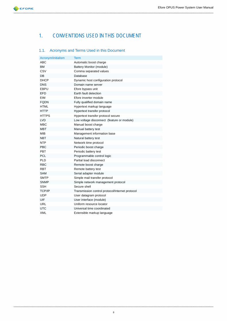
1.1. Acronyms and Terms Used in this Document
Acronym/initialism Term ABC Automatic boost chargeBM Battery Monitor (module)CSV Comma separated valuesDB DatabaseDHCP Dynamic host con guration protocolDNS Domain name serverEBPU Efore bypass unitEFD Earth fault detectionEIM Efore inverter moduleFQDN Fully quali ed domain nameHTML Hypertext markup languageHTTP Hypertext transfer protocolHTTPS Hypertext transfer protocol secureLVD Low voltage disconnect (feature or module)MBC Manual boost chargeMBT Manual battery testMIB Management information baseNBT Natural battery testNTP Network time protocolPBC Periodic boost chargePBT Periodic battery testPCL Programmable control logicPLD Partial load disconnectRBC Remote boost chargeRBT Remote battery testSAM Serial adapter moduleSMTP Simple mail transfer protocolSNMP Simple network management protocolSSH Secure shellTCP/IP Transmission control protocol/Internet protocolUDP User datagram protocolUIF User interface (module)URL Uniform resource locatorUTC Universal time coordinatedXML Extensible markup language
Efore OPUS Power System User Manual
9
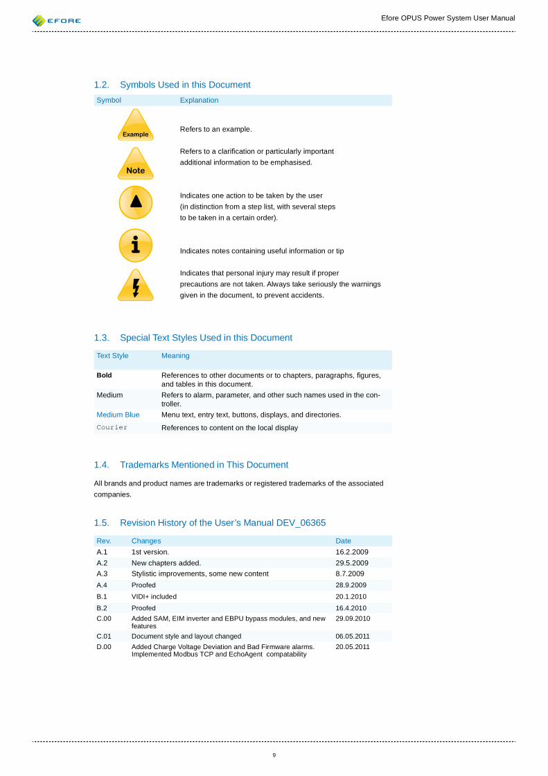
1.2. Symbols Used in this Document Symbol Explanation
Refers to an example.
Refers to a clari cation or particularly important additional information to be emphasised.
Indicates one action to be taken by the user (in distinction from a step list, with several steps to be taken in a certain order).
Indicates notes containing useful information or tip
Indicates that personal injury may result if proper precautions are not taken. Always take seriously the warnings given in the document, to prevent accidents.
1.3. Special Text Styles Used in this Document
Text Style Meaning
Bold References to other documents or to chapters, paragraphs, gures, and tables in this document.
Medium Refers to alarm, parameter, and other such names used in the con-troller.
Medium Blue Menu text, entry text, buttons, displays, and directories.
Courier References to content on the local display
1.4. Trademarks Mentioned in This Document
All brands and product names are trademarks or registered trademarks of the associated companies.
1.5. Revision History of the User’s Manual DEV_06365
Rev. Changes Date A.1 1st version. 16.2.2009A.2 New chapters added. 29.5.2009A.3 Stylistic improvements, some new content 8.7.2009A.4 Proofed 28.9.2009
B.1 VIDI+ included 20.1.2010
B.2 Proofed 16.4.2010C.00 Added SAM, EIM inverter and EBPU bypass modules, and new
features29.09.2010
C.01 Document style and layout changed 06.05.2011D.00 Added Charge Voltage Deviation and Bad Firmware alarms.
Implemented Modbus TCP and EchoAgent compatability20.05.2011
Efore OPUS Power System User Manual
10
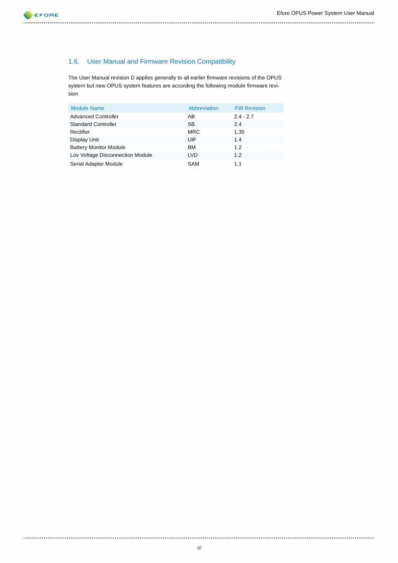
1.6. User Manual and Firmware Revision Compatibility
The User Manual revision D applies generally to all earlier rmware revisions of the OPUS system but new OPUS system features are according the following module rmware revi-sion
Module Name Abbreviation FW RevisionAdvanced Controller AB 2.4 - 2.7Standard Controller SB 2.4Recti er MRC 1.35Display Unit UIF 1.4Battery Monitor Module BM 1.2Lov Voltage Disconnection Module LVD 1.2
Serial Adapter Module SAM 1.1
Efore OPUS Power System User Manual
11
2. INTRODUCTION
An OPUS power system has ve main parts:
1. System modules2. Recti ers 3. Distribution 4. Batteries5. Inverters and bypass switches
This document is the user’s manual for the whole OPUS system, but the main emphasis is on the system controller functionality. Electromechanical installation and maintenance tasks are covered in the Installation and Start-up Manual for the system.
2.1. System ModulesThe following two modules are installed in all standard OPUS systems:
• VIDI+ system controller module • UIF (user interface) module
The VIDI+ system controller is a supervisor of an OPUS power system. The task of the system controller is to control and monitor system modules and functions. The VIDI+ controller consist of two separate boards, the standard controller and the advanced control-ler. In addition to the controller module can be included an IO board which contains an input for Earth Fault Detection, eight more alarm/temperature inputs and alarm relays. The VIDI+ controller provides a comprehensive but still easy-to-use local user interface, which can be accessed via the UIF module. In addition to the functionality of the local UIF a remote Web or terminal user interface via Ethernet or serial port connection provides more information from the system and enables among others:
• Event log and enhanced alarm log• Battery test logs and graphical presentation of battery tests• System power, battery temperature and battery discharge logs• Log data exporting• More con guration options• SNMP and SMTP alarm noti cation • Device naming
In addition to the VIDI+ and UIF modules, the following system modules are available:
• DFM (Distibution Fuse) module for monitoring load fuses• LVD (Low Voltage Disconnect) module for additional LVD control, cur-
rent measurement and alarm/temperature inputs• BM (Battery Monitor) module for battery block voltage measurements,
current measurement and alarm/temperature inputs• SAM (Serial Adapter) module for different serial interfaces
Efore OPUS Power System User Manual
12
2.2. Controller Modules and Busses
As the system controller module is the brains of the power system, all the system modules (UIF, recti ers, etc.) are connected to it. The OPUS power system uses a digital control bus called PowerCAN to provide communication between the system modules. PowerCAN is based on industry-standard CAN bus technology, but the communication protocol is proprietary to Efore.
A VIDI+ controller has two separate CAN busses:
ExtBus Extension module bus. All extension modules, such as LVD, BM and SAM modules, are connected to this bus. The UIF module is also connected to this bus, although it has a dedicated connector on the system controller module.
RectBus1 Recti er bus 1. All PowerCAN-compatible recti er modules, such as MRC recti ers, are connected to this bus.
In addition to the CAN busses, the controller module has many connections for internal and external signals such as voltage and current measurement, LVD control, alarm and temperature inputs, and alarm outputs.
The UIF module provides a local user interface, and it features a graphical LCD display and input controls.
The PowerCAN busses must be terminated at both ends with 120 ohm resistors. This can be accomplished with small RJ-45 terminator plugs which are shipped with the system. In a normal system con guration, the plugs are only installed on only one end of the bus. The ExtBus bus is terminated internally at the UIF module, and the RectBus1 is terminated internally at the VIDI+ system control module.
If only one end of a PowerCAN bus is terminated, the bus works when the cable is short enough and there are not many devices on the bus. However, to ensure proper functional-ity in all circumstances, it is recommended to make sure the bus is always terminated at both ends.
A SAM module enables the OPUS system connection to an external serial interface bus or a module using a serial interface bus connection to the VIDI+ controller. EIM inverter and EBPU bypass modules used in the OPUS system are controlled to the VIDI+ controller via a SAM module.
2.3. Voltage Versions There are OPUS power systems available for all common DC voltages used in industrial and telecommunication applications: 24 V, 48 V, 60 V, 110 V, 125 V and 220 V. The differ-ent voltage versions usually require different recti ers, electromechanics, and batteries. However, the same VIDI+ system controller modules can be used for all voltage versions. The voltage version and all of the related voltage parameters are de ned by the VIDI+ parameter system.
2.4. Recti ersThe VIDI+ controller is designed to work with different recti er modules. However, this manual assumes that MRC recti ers are being used.
Efore OPUS Power System User Manual
13
Normally, the recti ers are controlled and monitored by the VIDI+ controller. The control-ler controls output voltage and power levels of the recti ers on the basis of battery charge modes, temperatures and various control algorithms. Problems in recti ers will be indicated as alarms on the user interfaces.
The recti ers can also work independently from the system controller. If a recti er cannot communicate with the system controller, the recti er restores the default voltage. An excep-tion to this is when the default voltage is higher than previous voltage set by the system controller, in which case the default voltage is not restored.
The default voltage depends on the voltage version of the recti er. The default voltage and the Recti er Voltage Group parameter of MRC recti ers are presented in the following table:
Voltage Version Default Voltage Recti er Voltage Group Parameter24 V 27.24V 248 V 54.48 V 460 V 68.1 V 5110 V 122.58 V 9125 V 136.8 V 10220 V 245.3 V 18
Load sharing functionality of the recti ers does not require the presence of the system controller. All recti ers sharing the same load must be interconnected with a CAN bus, and at least one end of the CAN bus must be terminated.
2.5. Inverter and Bypass ModulesEIM inverter and EBPU bypass modules are controlled and monitored by the VIDI+ control-ler via the SAM module. By the controller are set the operation parameters to the modules. The controller shows measurements from the modules and activates alarms concerning the modules if the alarms are enabled and alarm conditions are lled up.
The EIM inverter and EBPU bypass modules can also work independently from the system controller. If the modules cannot communicate with the VIDI+ controller, the modules continue working according the set parameters but measurement and alarm information is no longer updated. If the VIDI+ controller is however functional, The Communication Error alarm from the modules is activated.
2.6. Batteries
The OPUS power system is designed to be used with lead-acid, nickel-cadmium and nickel-metal hybride batteries. Any battery type that behaves similarly to these can be used, provided that the cell voltage parameters are set up properly.
The following battery-related terms are used in this document and the VIDI+ controller in general:
Cell The smallest natural battery element. The nominal voltage of a single cell is usually about two volts for the common battery types.
Block A number (one or more) of battery cells connected in series, forming a physical block that can be replaced as a single entity. Usually a battery block consists of one, three, or six battery cells. For example, the standard lead-acid battery block used in cars contains six battery cells and has a nominal voltage of 12 volts.
Efore OPUS Power System User Manual
14
String A number (one or more) of battery blocks connected in series. The nominal voltage of a battery string equals the voltage version of the system. For example, a 48 V system usually contains one or more strings each having four 12 V blocks.
Bank A number (one or more) of battery strings connected in parallel.
As the batteries are often the most expensive component of a power system, the VIDI+ controller has many features for protecting batteries, extending their life, and monitoring their condition:
• Low voltage disconnect protects the battery from deep discharge• Periodic boost charge extends battery life by equalising the cell
voltages • Temperature compensation extends battery life by reducing charge
voltage in high temperatures • Battery tests can be used to monitor battery condition • Various alarms can be used to inform the operator about bad operation
conditions
In a recti er power system, batteries are charged by recti er (AC-to-DC converter) mod-ules. When there is no AC (mains power) available, the batteries supply all the current required by the load, until the mains return or the batteries are exhausted.
2.6.1. Battery Con guration
In the OPUS system is three parameters that affects to the system voltage version. These are system Voltage Version, Cells Per Block and Nominal Cell Voltage. Usually the nominal cell voltage of a battery is 2 V. Set the other two parameters according an installed battery. The Cells Per Block parameter means a number of cells in one battery block. The default value to this parameter in the VIDI+ controller is six, which is commonly used battery type (6*2 V = 12 V). The system Voltage Version parameter describes how many block is con-nected in series in a battery string. Below are instructions how to set the parameters.
If you use the Web or Terminal interface, you must log in as an admin user to be able to change parameters. More information of different user levels on the remote interface can be found from Section 5.7 (User Levels). If the local user interface is being used and the password for the local user interface is nonzero, the password will be asked before any parameter can be changed.
1. Check that the Expert Mode parameter is Enabled from System Pa-rameters. This enables that all parameters are shown on the display and they can be changed.
2. Check that a battery fuse (fuses) is switched off.3. Set a value corresponding the battery to the Cells Per Block parameter
of the System Parameters. 4. Next the controller shows related parameters to this parameter change
and new values of the related parameters. These values can be changed manually but it is easier to accept these values and continue changes as below guided.
5. Next change the parameter Voltage Version on the System Parameters to a right value.
Efore OPUS Power System User Manual
15
6. Next the controller shows related parameters to this parameter change and new values of the related parameters. In this phase change the Recti er Voltage Version parameter to the right value and accept others as they are. The Recti er Voltage Version parameter for MRC recti ers is: 2 for 24V, 4 for 48V, 5 for 60V, 9 for 110V, 10 for 125V and 18 for 220V.
7. If you didn’t change the recti er voltage version parameter in the previ-ous step but accepted all parameters, you can change it now from the System Parameters.
8. Check battery cell voltage values from the Parameters • Battery Pa-rameters. If the values are not corresponding the battery, change them.
9. After these actions test the system output voltage levels in different charge modes: the oat charge (FC), the boost charge (BC), the tem-perature compensation (TC), the battery test (BT).
10. If the system is at the time in FC mode, check that the system output voltage is correct.
11. If a temperature sensor is connected to the system and it is con gured as a battery temperature sensor, enable the TC mode from the Param-eters • Charge Parameters • Temperature Compensation. Check that the system output voltage level corresponds the charge mode and the temperature level. Disable the TC mode.
12. Select Start Manual Boost Charging from the Actions menu. Check that the system output voltage level is correct. Stop the MBC.
13. Select from the Actions menu Start Manual Battery Test. The system output voltage is for a moment on the recti er’s lowest output voltage level but then the battery test is terminated and the system returns to the previous charge mode.
14. Switch on the battery fuse (fuses).15. If the battery is empty it should be in the Charge State.
2.7. Modbus TCPEfore Opus system’s Modbus/TCP implementation supports two simultaneous client-server connection at a time. Server side will end connection, if there is over 1 minute interval between messages. It is recommended for client side to send messages to server at least once in 30 seconds.
Opus system’s server will wait for Modbus requests on Modbus default TCP port 502
Following modbus functions can be used:
• read multiple registers (fc 3)• read/write registers (fc 23)
2.7.1. Memory Areas
‘Holding registers’ area is used to provide information about the system. Each memory address holds 16 bits of data and the data can be only read. Writing to ‘holding registers’ area is discarded. Because these are holding registers, address range is 4:0001 – 4:0039. Unused areas between the used data areas can be read. They are set to ‘0’.
Other memory areas are not used and will return illegal data address if they are tried to read/write.
Efore OPUS Power System User Manual
16
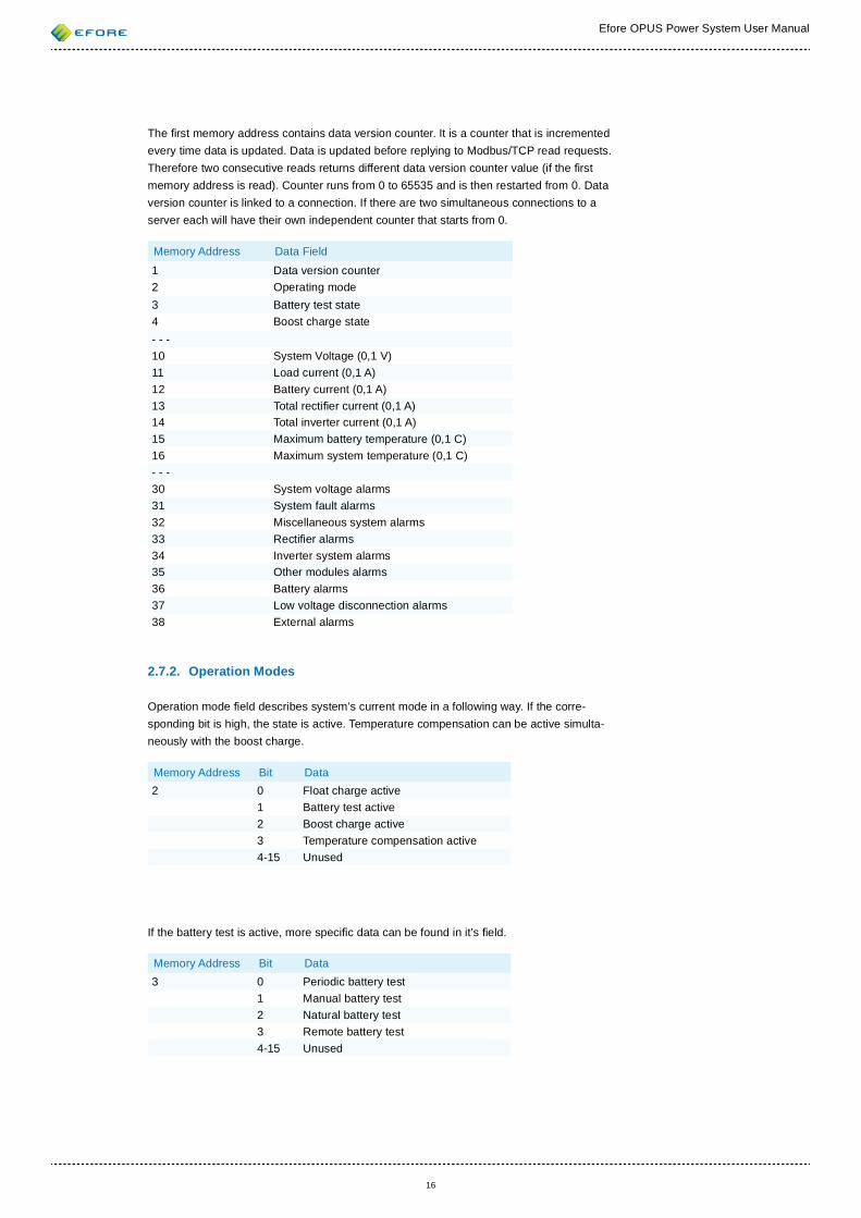
The rst memory address contains data version counter. It is a counter that is incremented every time data is updated. Data is updated before replying to Modbus/TCP read requests. Therefore two consecutive reads returns different data version counter value (if the rst memory address is read). Counter runs from 0 to 65535 and is then restarted from 0. Data version counter is linked to a connection. If there are two simultaneous connections to a server each will have their own independent counter that starts from 0.
Memory Address Data Field
1 Data version counter2 Operating mode3 Battery test state4 Boost charge state- - - 10 System Voltage (0,1 V)11 Load current (0,1 A)12 Battery current (0,1 A)13 Total recti er current (0,1 A)14 Total inverter current (0,1 A)15 Maximum battery temperature (0,1 C)16 Maximum system temperature (0,1 C)- - -30 System voltage alarms31 System fault alarms32 Miscellaneous system alarms33 Recti er alarms34 Inverter system alarms35 Other modules alarms36 Battery alarms37 Low voltage disconnection alarms38 External alarms
2.7.2. Operation Modes
Operation mode eld describes system’s current mode in a following way. If the corre-sponding bit is high, the state is active. Temperature compensation can be active simulta-neously with the boost charge.
Memory Address Bit Data2 0 Float charge active
1 Battery test active2 Boost charge active3 Temperature compensation active4-15 Unused
If the battery test is active, more speci c data can be found in it’s eld.
Memory Address Bit Data3 0 Periodic battery test
1 Manual battery test2 Natural battery test3 Remote battery test4-15 Unused
Efore OPUS Power System User Manual
17
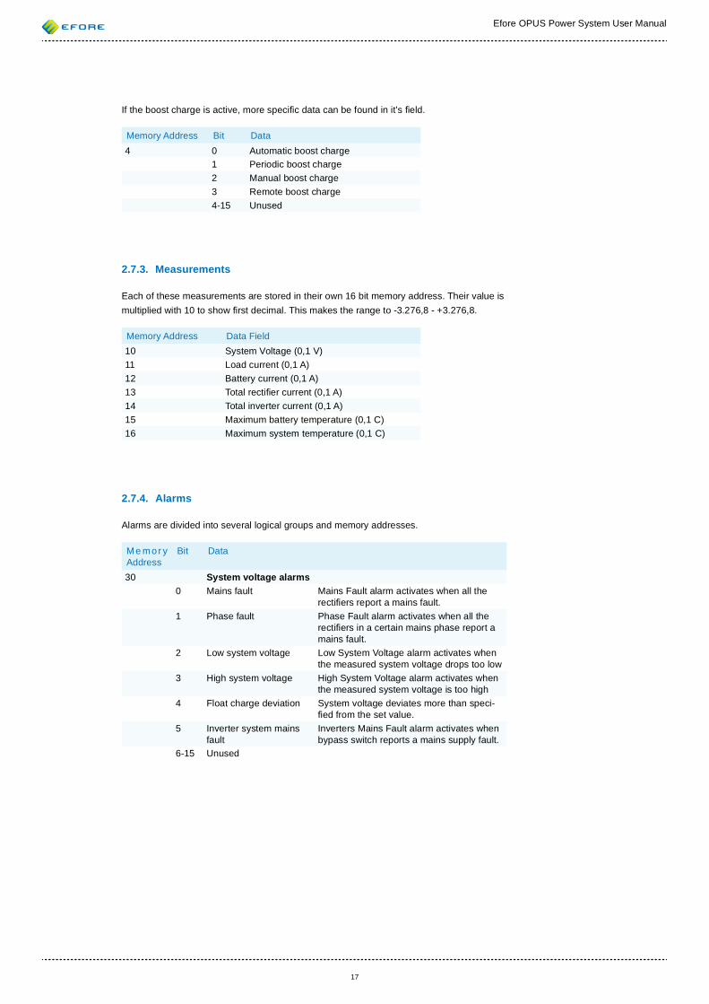
If the boost charge is active, more speci c data can be found in it’s eld.
Memory Address Bit Data4 0 Automatic boost charge
1 Periodic boost charge2 Manual boost charge3 Remote boost charge4-15 Unused
2.7.3. Measurements
Each of these measurements are stored in their own 16 bit memory address. Their value is multiplied with 10 to show rst decimal. This makes the range to -3.276,8 - +3.276,8.
Memory Address Data Field10 System Voltage (0,1 V)11 Load current (0,1 A)12 Battery current (0,1 A)13 Total recti er current (0,1 A)14 Total inverter current (0,1 A)15 Maximum battery temperature (0,1 C)16 Maximum system temperature (0,1 C)
2.7.4. Alarms
Alarms are divided into several logical groups and memory addresses.
Me mor y Address
Bit Data
30 System voltage alarms0 Mains fault Mains Fault alarm activates when all the
recti ers report a mains fault.1 Phase fault Phase Fault alarm activates when all the
recti ers in a certain mains phase report a mains fault.
2 Low system voltage Low System Voltage alarm activates when the measured system voltage drops too low
3 High system voltage High System Voltage alarm activates when the measured system voltage is too high
4 Float charge deviation System voltage deviates more than speci- ed from the set value.
5 Inverter system mains fault
Inverters Mains Fault alarm activates when bypass switch reports a mains supply fault.
6-15 Unused
Efore OPUS Power System User Manual
18
Me mor y Address
Bit Data
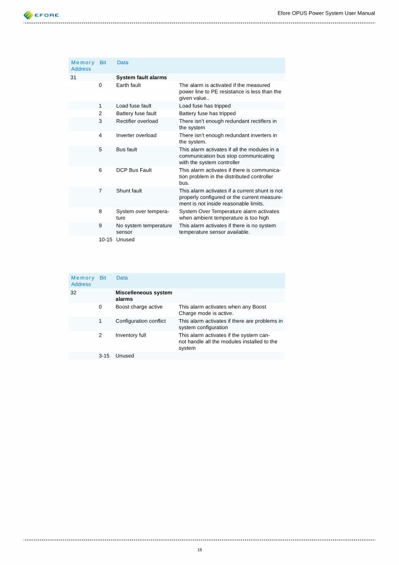
31 System fault alarms0 Earth fault The alarm is activated if the measured
power line to PE resistance is less than the given value..
1 Load fuse fault Load fuse has tripped2 Battery fuse fault Battery fuse has tripped3 Recti er overload There isn’t enough redundant recti ers in
the system4 Inverter overload There isn’t enough redundant inverters in
the system.5 Bus fault This alarm activates if all the modules in a
communication bus stop communicating with the system controller
6 DCP Bus Fault This alarm activates if there is communica-tion problem in the distributed controller bus.
7 Shunt fault This alarm activates if a current shunt is not properly con gured or the current measure-ment is not inside reasonable limits.
8 System over tempera-ture
System Over Temperature alarm activates when ambient temperature is too high
9 No system temperature sensor
This alarm activates if there is no system temperature sensor available.
10-15 Unused
Me mor y Address
Bit Data
32 Miscelleneous system alarms
0 Boost charge active This alarm activates when any Boost Charge mode is active.
1 Con guration con ict This alarm activates if there are problems in system con guration
2 Inventory full This alarm activates if the system can-not handle all the modules installed to the system
3-15 Unused
Efore OPUS Power System User Manual
19
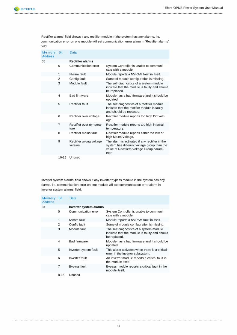
‘Recti er alarms’ eld shows if any recti er module in the system has any alarms. i.e. communication error on one module will set communication error alarm in ‘Recti er alarms’ eld.
Memo ry Address
Bit Data
33 Recti er alarms0 Communication error System Controller is unable to communi-
cate with a module.1 Nvram fault Module reports a NVRAM fault in itself. 2 Con g fault Some of module con guration is missing.3 Module fault The self-diagnostics of a system module
indicate that the module is faulty and should be replaced.
4 Bad rmware Module has a bad rmware and it should be updated.
5 Recti er fault The self-diagnostics of a recti er module indicate that the recti er module is faulty and should be replaced.
6 Recti er over voltage Recti er module reports too high DC volt-age.
7 Recti er over tempera-ture
Recti er module reports too high internal temperature.
8 Recti er mains fault Recti er module reports either too low or high Mains Voltage.
9 Recti er wrong voltage version
The alarm is activated if any recti er in the system has different voltage group than the value of Recti ers Voltage Group param-eter.
10-15 Unused
‘Inverter system alarms’ eld shows if any inverter/bypass module in the system has any alarms. i.e. communication error on one module will set communication error alarm in ‘Inverter system alarms’ eld.
Memory Address
Bit Data
34 Inverter system alarms0 Communication error System Controller is unable to communi-
cate with a module.1 Nvram fault Module reports a NVRAM fault in itself. 2 Con g fault Some of module con guration is missing.3 Module fault The self-diagnostics of a system module
indicate that the module is faulty and should be replaced.
4 Bad rmware Module has a bad rmware and it should be updated.
5 Inverter system fault This alarm activates when there is a critical error in the inverter subsystem.
6 Inverter fault An inverter module reports a critical fault in the module itself.
7 Bypass fault Bypass module reports a critical fault in the module itself.
8-15 Unused
Efore OPUS Power System User Manual
20
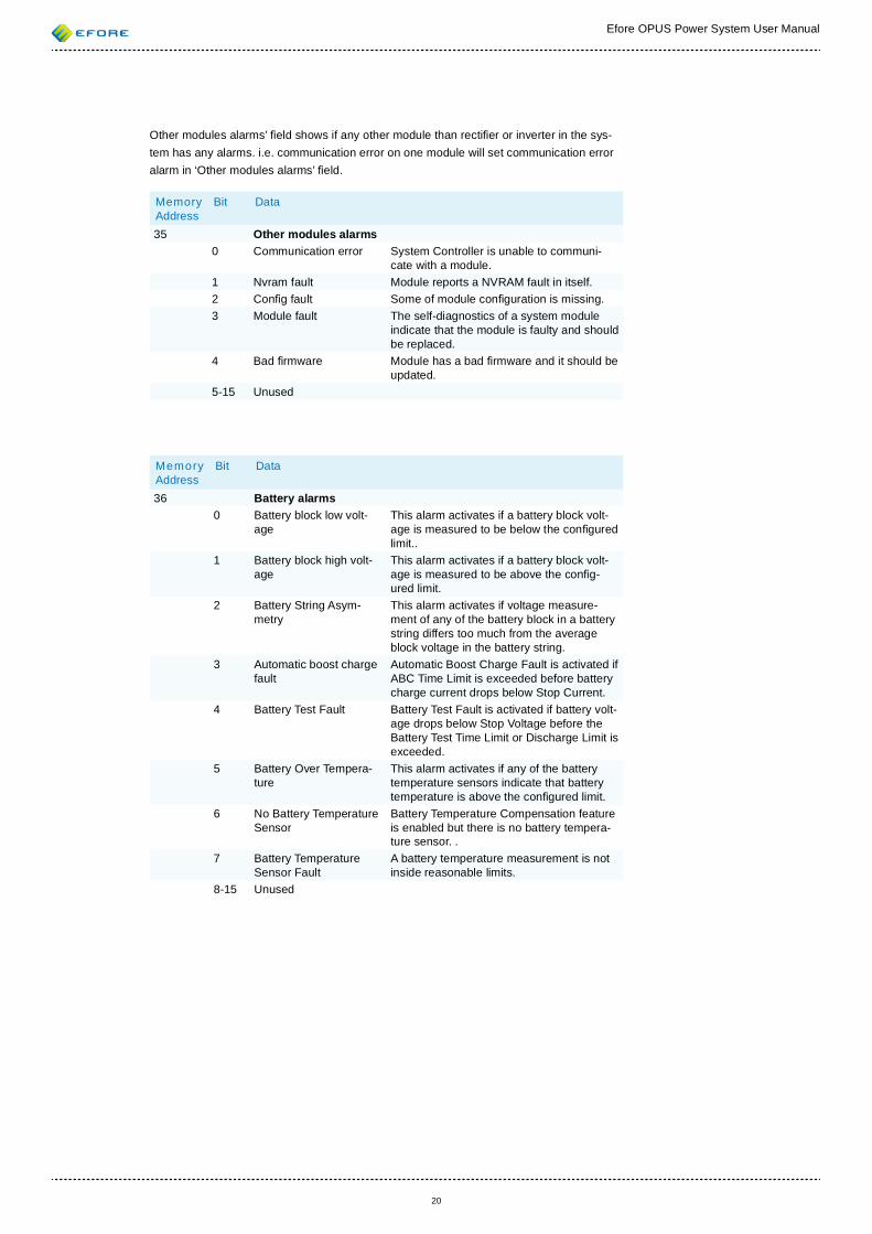
Other modules alarms’ eld shows if any other module than recti er or inverter in the sys-tem has any alarms. i.e. communication error on one module will set communication error alarm in ‘Other modules alarms’ eld.
Memory Address
Bit Data
35 Other modules alarms0 Communication error System Controller is unable to communi-
cate with a module.1 Nvram fault Module reports a NVRAM fault in itself. 2 Con g fault Some of module con guration is missing.3 Module fault The self-diagnostics of a system module
indicate that the module is faulty and should be replaced.
4 Bad rmware Module has a bad rmware and it should be updated.
5-15 Unused
Memory Address
Bit Data
36 Battery alarms0 Battery block low volt-
ageThis alarm activates if a battery block volt-age is measured to be below the con gured limit..
1 Battery block high volt-age
This alarm activates if a battery block volt-age is measured to be above the con g-ured limit.
2 Battery String Asym-metry
This alarm activates if voltage measure-ment of any of the battery block in a battery string differs too much from the average block voltage in the battery string.
3 Automatic boost charge fault
Automatic Boost Charge Fault is activated if ABC Time Limit is exceeded before battery charge current drops below Stop Current.
4 Battery Test Fault Battery Test Fault is activated if battery volt-age drops below Stop Voltage before the Battery Test Time Limit or Discharge Limit is exceeded.
5 Battery Over Tempera-ture
This alarm activates if any of the battery temperature sensors indicate that battery temperature is above the con gured limit.
6 No Battery Temperature Sensor
Battery Temperature Compensation feature is enabled but there is no battery tempera-ture sensor. .
7 Battery Temperature Sensor Fault
A battery temperature measurement is not inside reasonable limits.
8-15 Unused
Efore OPUS Power System User Manual
21
Memory Address
Bit Data
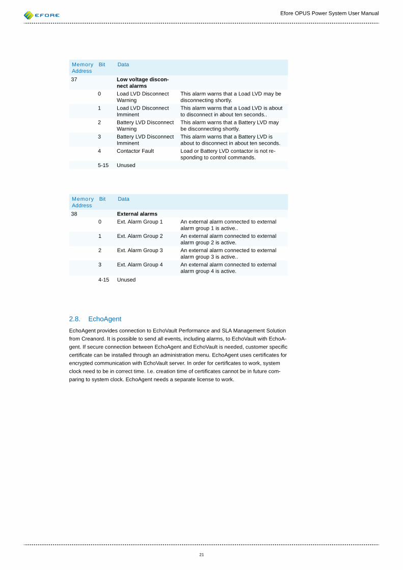
37 Low voltage discon-nect alarms
0 Load LVD Disconnect Warning
This alarm warns that a Load LVD may be disconnecting shortly.
1 Load LVD Disconnect Imminent
This alarm warns that a Load LVD is about to disconnect in about ten seconds..
2 Battery LVD Disconnect Warning
This alarm warns that a Battery LVD may be disconnecting shortly.
3 Battery LVD Disconnect Imminent
This alarm warns that a Battery LVD is about to disconnect in about ten seconds.
4 Contactor Fault Load or Battery LVD contactor is not re-sponding to control commands.
5-15 Unused
Memory Address
Bit Data
38 External alarms0 Ext. Alarm Group 1 An external alarm connected to external
alarm group 1 is active..1 Ext. Alarm Group 2 An external alarm connected to external
alarm group 2 is active.2 Ext. Alarm Group 3 An external alarm connected to external
alarm group 3 is active..3 Ext. Alarm Group 4 An external alarm connected to external
alarm group 4 is active.4-15 Unused
2.8. EchoAgentEchoAgent provides connection to EchoVault Performance and SLA Management Solution from Creanord. It is possible to send all events, including alarms, to EchoVault with EchoA-gent. If secure connection between EchoAgent and EchoVault is needed, customer speci c certi cate can be installed through an administration menu. EchoAgent uses certi cates for encrypted communication with EchoVault server. In order for certi cates to work, system clock need to be in correct time. I.e. creation time of certi cates cannot be in future com-paring to system clock. EchoAgent needs a separate license to work.
Efore OPUS Power System User Manual
22
3. PRINCIPLES OF OPERATION
3.1. Parameter System
Because of VIDI+’s highly exible design, it can be used in many different applications with different voltage, current and power levels, battery types, etc. However, exibility often en-tails complexity. One of the main objectives in the design of the VIDI+ controller has been to hide this complexity from the user.
One of those points is the parameter system of VIDI+. All modern power system controllers have quite a collection of parameters. This is true for VIDI+ also. In VIDI+, those param-eters are also interlinked. This means that a parameter may affect default, minimum, and maximum values of other parameters, in what are called parameter dependencies.
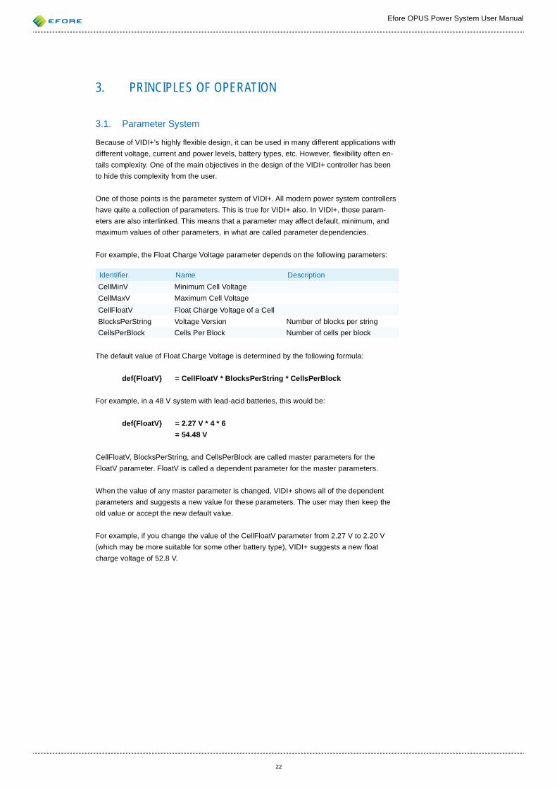
For example, the Float Charge Voltage parameter depends on the following parameters:
Identi er Name Description CellMinV Minimum Cell VoltageCellMaxV Maximum Cell VoltageCellFloatV Float Charge Voltage of a CellBlocksPerString Voltage Version Number of blocks per stringCellsPerBlock Cells Per Block Number of cells per block
The default value of Float Charge Voltage is determined by the following formula:
def{FloatV} = CellFloatV * BlocksPerString * CellsPerBlock
For example, in a 48 V system with lead-acid batteries, this would be:
def{FloatV} = 2.27 V * 4 * 6 = 54.48 V
CellFloatV, BlocksPerString, and CellsPerBlock are called master parameters for the FloatV parameter. FloatV is called a dependent parameter for the master parameters.
When the value of any master parameter is changed, VIDI+ shows all of the dependent parameters and suggests a new value for these parameters. The user may then keep the old value or accept the new default value.
For example, if you change the value of the CellFloatV parameter from 2.27 V to 2.20 V (which may be more suitable for some other battery type), VIDI+ suggests a new oat charge voltage of 52.8 V.
Efore OPUS Power System User Manual
23
Some parameters, such as CellFloatV and other cell voltage parameters, are considered ‘expert-mode’ parameters, as they need not be changed during normal operation of a power system. If such parameters need to be changed or audited, the Expert Mode parameter, in the System Parameters group, needs to be enabled.
In the user interface, the full parameter names are always used instead of the parameter identi ers. The identi ers may be used in some places in the documentation to clarify the mathematical nota-tion and keep it concise. The parameter of the VIDI+ controller are presented in Section 7 (Parameters).
Minimum and maximum dependencies affect the minimum and maximum value for a pa-rameter, naturally. For example, the minimum value for oat charge voltage is determined by the following formula:
min{FloatV} = CellMinV * BlocksPerString * CellsPerBlock
An example for a 48 V system is: min{FloatV} = 1.75 V * 4 * 6 = 42.00 V
Thus, you cannot change the value of the oat charge parameter to less than 42 volts. This should cover all normal situations. However, should some special situation so require, you can go below this limit by changing the CellMinV parameter to less than 1.75 V.
If a master parameter is changed such that the value of a dependent parameter leaves the allowed range, VIDI+ prompts for new values for each such parameter.
Detailed instructions on auditing and changing parameters using the local user interface are available in Section 4.6 (Parameters).
3.2. Busses, Modules, Ports, and Devices
3.2.1. Busses and Modules
Different types of modules can be connected to a VIDI+ controller via the PowerCAN bus. The VIDI+ system controller is a module itself, and so is the UIF module.
As stated earlier, the VIDI+ controller has two PowerCAN busses, named ExtBus and RectBus1. In addition to these, there is a virtual bus called Controller Bus in between the standard and advanced control modules.
Efore OPUS Power System User Manual
24
The serial adapter module (SAM) of the OPUS system, connected to the ExtBus, provides a serial interface bus enabling a serial interface connection to other modules or outside the OPUS system. The EIM inverter and EBPU bypass modules used in the OPUS system communicate via a SAM module. The VIDI+ controller reads measurement and alarm information from the inverter and bypass modules. The VIDI+ controller can also set some parameters to the modules. If there is a need to see more detailed information from the inverter or bypass modules, see the inverter and bypass module manuals.
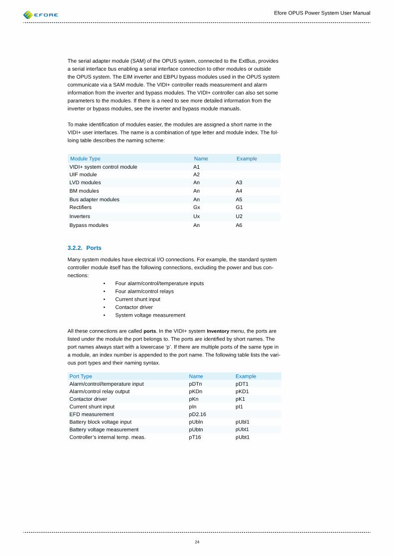
To make identi cation of modules easier, the modules are assigned a short name in the VIDI+ user interfaces. The name is a combination of type letter and module index. The fol-loing table describes the naming scheme:
Module Type Name Example VIDI+ system control module A1UIF module A2LVD modules An A3BM modules An A4Bus adapter modules An A5Recti ers Gx G1
Inverters Ux U2
Bypass modules An A6
3.2.2. Ports
Many system modules have electrical I/O connections. For example, the standard system controller module itself has the following connections, excluding the power and bus con-nections:
• Four alarm/control/temperature inputs• Four alarm/control relays • Current shunt input• Contactor driver • System voltage measurement
All these connections are called ports. In the VIDI+ system Inventory menu, the ports are listed under the module the port belongs to. The ports are identi ed by short names. The port names always start with a lowercase ‘p’. If there are multiple ports of the same type in a module, an index number is appended to the port name. The following table lists the vari-ous port types and their naming syntax.
Port Type Name Example Alarm/control/temperature input pDTn pDT1Alarm/control relay output pKDn pKD1Contactor driver pKn pK1Current shunt input pIn pI1EFD measurement pD2.16Battery block voltage input pUbln pUbl1Battery voltage measurement pUbtn pUbt1Controller’s internal temp. meas. pT16 pUbt1
Efore OPUS Power System User Manual
25
3.2.3. Devices
Each port can be con gured for certain use or uses. Con gured ports are called Devices. Examples of devices are:
• Alarm/control/temp input con gured as Battery Fuse Alarm device• Alarm/control/temp input con gured as Battery Temperature Sensor
device• Contactor driver con gured as Load LVD device (PLD)
There can be multiple devices of the same type in a system. For this reason, the devices are numbered. The numbers are called device indices or sometimes device IDs. For exam-ple, the rst battery LVD device has device index 1.
In addition to plain index numbering, some devices can be grouped. Each group has its own number. For example, distribution fuses are usually numbered by their group instead of as individual fuses (the state of which is usually unknown to the system controller).
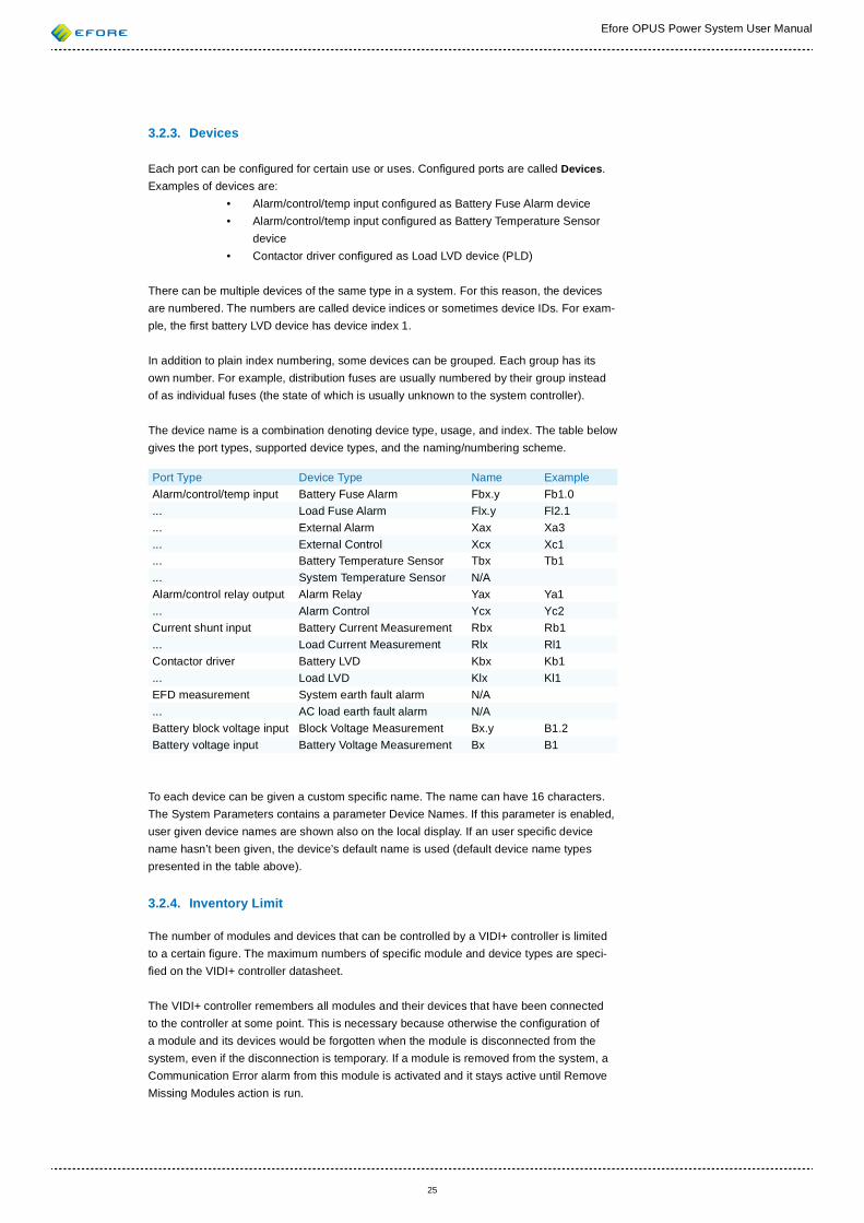
The device name is a combination denoting device type, usage, and index. The table below gives the port types, supported device types, and the naming/numbering scheme.
Port Type Device Type Name ExampleAlarm/control/temp input Battery Fuse Alarm Fbx.y Fb1.0... Load Fuse Alarm Flx.y Fl2.1... External Alarm Xax Xa3... External Control Xcx Xc1... Battery Temperature Sensor Tbx Tb1... System Temperature Sensor N/AAlarm/control relay output Alarm Relay Yax Ya1... Alarm Control Ycx Yc2Current shunt input Battery Current Measurement Rbx Rb1... Load Current Measurement Rlx Rl1Contactor driver Battery LVD Kbx Kb1... Load LVD Klx Kl1EFD measurement System earth fault alarm N/A... AC load earth fault alarm N/ABattery block voltage input Block Voltage Measurement Bx.y B1.2Battery voltage input Battery Voltage Measurement Bx B1
To each device can be given a custom speci c name. The name can have 16 characters. The System Parameters contains a parameter Device Names. If this parameter is enabled, user given device names are shown also on the local display. If an user speci c device name hasn’t been given, the device’s default name is used (default device name types presented in the table above).
3.2.4. Inventory Limit
The number of modules and devices that can be controlled by a VIDI+ controller is limited to a certain gure. The maximum numbers of speci c module and device types are speci- ed on the VIDI+ controller datasheet.
The VIDI+ controller remembers all modules and their devices that have been connected to the controller at some point. This is necessary because otherwise the con guration of a module and its devices would be forgotten when the module is disconnected from the system, even if the disconnection is temporary. If a module is removed from the system, a Communication Error alarm from this module is activated and it stays active until Remove Missing Modules action is run.
Efore OPUS Power System User Manual
26
Inventory limi ts may be exceeded when new units are installed or units are replaced with new ones. In this situation, the controller tries to free space in its inventory by discarding old (disconnected) modules of the same type. If this doesn’t help, the new modules will be ignored. This kind of situation will be signalled by an Inventory Full alarm.
The full inventory problem may be solved by manually commanding the controller to remove all missing modules from inventory. This command can be executed from the user interfaces.
3.3. Charge Modes When mains power is available, VIDI+ adjusts the output voltage of the recti ers according to the system charge state. The supported charge states are described below.
3.3.1. Float Charge
This is the default charge state. The batteries are charged with a voltage optimal for continuous operation. The oat charge voltage is speci ed by the Float Charge Voltage parameter, in the Charge Parameters group. The default oat charge voltage is 2.27 V per battery cell.
The temperature compensation feature can be used in Float Charge mode.
3.3.2. Boost Charge
Boost charging enables faster battery charging and equalises battery cell voltages. During boost charge, batteries are charged with higher voltage than in oat charge. The default boost charge voltage is 2.40 V per battery cell.
Boost charge can be activated manually, automatically after a mains fault, periodically at set intervals or with a remote signal, which is connected to one input of the OPUS system.
If enabled, automatic boost charge (ABC) begins after a mains fault once the battery charge current exceeds the Start Current limit for ve seconds. The default value of Start Current is 10% of the nominal system current. Automatic boost charge can also start after controller restart, provided that the Start Current value is exceeded, as a prolonged mains fault usually causes the controller to power down.
The automatic boost charge will stop after the charge current drops below the Stop Cur-rent value set or when the maximum boost charge time is exceeded. The default for Stop Current value is 5 % and the default Time Limit value is 20 hours.
If periodic boost charge (PBC) is enabled, the system will automatically boost charge the batteries at the intervals speci ed. This helps to keep block and cell voltages balanced. You can set the boost charging frequency.
The remote boost charge (RBC) method enables the boost charge mode starting with an external input signal. The RBC settings are done using the con gurable logic of the VIDI+ controller. The con gurable logic can be accessed only via a remote user interface (web or terminal interface). The external input signal must be con gured as a control input. This will be done from the inventory menu (see more information from the Section 8.9 (Alarm Inputs) ). When the input is set as a control input, it is shown on the Control Inputs list of the con gurable logic page of the VIDI+ controller under the Administration menu. Open the Control Inputs list and de ne settings. You can invert the input signal state, set the ac-tivation or deactivation delay to the action. Select from the System Control list Start Boost Charging. More detailed instructions to the con gurable logic settings can be found from
Efore OPUS Power System User Manual
27
the help page of the web/terminal interface or from the Section 5.9.2 (Programmable Con- guration Logic). From the parameter page of the RBC (Parameters • Charge Parameters • Boost Charge • Remote Boost Charge) can be de ned whether the RBC is stopped if the external sinal’s state changes. On this page are de ned also other RBC parameters.
Periodic, automatic and remote boost charging methods are disabled if any of the following conditions are true:
• Battery test alarm is active (non-acknowledged)• Battery over temperature alarm is active• Battery temperature sensor fault alarm is active• ABC (automatic boost charge) fault alarm is active (non-acknowl-
edged)• Battery temperature is not within the allowed limits• Battery fuse alarm is active
Manual boost charging (MBC) is disabled if any of the alarms listed above is active and has not been acknowledged.
On the System Alarms exist the Boost Charge Active alarm (Parameters • Alarm Param-eters • System Alarms). If this alarm is enabled, its state is active always when any boost charge mode is active. With this alarm can be informed to outside the system that the system is in the boost charge mode. The same information can be given also with the con gurable logic using the System State event, more information on the Section 5.9.2 (Programmable Con guration Logic).
If boost charging does not begin as expected:
1. Check the alarms list2. Check the battery temperature
If any boost charge mode is active when a rmware updating to any system module is started, the boost charge mode will be terminated and the system goes to the oat charge mode.
3.3.3. Battery Charge Current Limiting
Charge current limiting is a feature that prevents batteries from being charged with an excessive current. Charge current limiting is disabled by default. It can be enabled from the Charge Current Control parameter group which belongs to Charge Parameters.
Battery charge current limiting works on two levels:
System-Wide Limit De ned under Charge Parameters, this limit is for total battery
current. Total battery current is the sum of individual battery cur-rent measurements.
Device-Speci c Limits These limits are de ned by the Charge Limit parameter for each
battery current measurement device.
The controller attempts to control the output voltage of recti ers such that none of the limits are exceeded. In other words, all of the charge current limits are in effect simultaneously.
Efore OPUS Power System User Manual
28
3.3.4. Battery Tests
Battery tests are used to monitor the state of the batteries. The system controller manages battery testing by lowering output voltage of the recti ers to a standby level. In this state, the recti ers will not source current until the battery voltage reaches the standby voltage. If the batteries are in poor condition and the battery voltage suddenly falls very low, the recti- ers will return to oat charge mode and supply power to the load without interruption.
The battery test ends successfully after a user-con gured time or energy limit has been exceeded. The energy limit will be exceeded when the con gured amount of energy, meas-ured in ampere-hours (Ah), has been discharged from the batteries. If the battery voltage drops below the Stop Voltage Limit parameter before time or energy limit is reached, the battery test fails. If the battery test fails, the controller activates Battery Test Fault alarm. Stop Voltage and Time Limit are con gurable parameters.
In the rst moments of a battery test, it is normal for the battery voltage to rst drop sig-ni cantly and then return to a higher level. To prevent this behaviour from causing failure of the battery test, two additional parameters are available: Shutdown Voltage and Ignore Time. At the beginning of the battery test, the Stop Voltage value is ignored until the time set as the Ignore Timer value has elapsed. During that time, only the Shutdown Voltage limit is in effect. If the battery voltage drops below Shutdown Voltage at any point in the battery test, the battery test fails.
VIDI+ controller features a precharge timer which is used to make sure battery tests are performed only on fully charged batteries. The precharge timer is reset on mains fault and controller start-up. Battery tests are only possible after the precharge timer has exceeded value of the Precharge Time parameter. However, VIDI+ user interfaces provide a possibil-ity to reset the precharge timer manually.
There are four variations of the battery test: Manual Battery Test (MBT), Periodic Battery Test (PBT), Natural Battery Test (NBT) and Remote Battery Test (RBT).
MBT can be started manually from a user interface.
PBT can be con gured to start a certain number of times per year. It is useful for automa-tion of the battery testing. However, PBT will not start if either any of the following alarms is active:
1. Battery Test Alarm 2. Battery Fuse Alarm3. Battery Over Temperature Alarm
Allowed starting time of the PBT can be de ned separately to each weekday. Also can be set ten date when PBT is forbidden.
NBT, when enabled, starts automatically when the system detects a mains fault. The test fails if the battery voltage drops below the limits before the mains fault ends and the con gured NBT Time Limit setting has not been exceeded. An active Battery Test Alarm prevents NBT starting.
RBT can be started via a remote signal which is connected to an input of the OPUS sys-tem. This input must be set as a Cotrol Input from the inventory menu (see more informa-tion from the Section 8.9 (Alarm Inputs)). The RBT settings are done using the con gura-ble logic of the VIDI+ controller. The con gurable logic can be accessed only via a remote user interface (web or terminal interface). When the input is set as the control input, it is shown on the Control Inputs list of the con gurable logic page of the VIDI+ controller under the Administration menu. Open the Control Inputs list and de ne settings. You can invert
Efore OPUS Power System User Manual
29
the input signal state, set the activation or deactivation delay to the action. Select from the System Control list Start Battery Test. More detailed instructions to the con gurable logic settings can be found from the help page of the web/terminal interface or from the Section 5.9.2 (Programmable Con guration Logic). From the parameter page of the RBT (Param-eters • Battery Tests • Remote Battery Test) can be de ned whether the RBT is stopped if the external signal’s state changes. On this page are de ned also other RBT parameters.
If a battery test fails, a battery test alarm is activated..
On the con gurable logic page exist the System State event where is the Battery Test Active state. The battery test active state is active always when any battery test mode is active. With this state signal can be informed to outside the system that a battery test is going on.
VIDI+ provides a battery test log which shows both successful and failed battery tests. Natural battery tests which have ended prematurely due to end of mains fault will be removed automatically from the battery test log. The battery test log can be accessed from the remote intefaces only. On the web interface it is possible to see graphical voltage-time or voltage-Ah curves representing the recorded battery tests.
VIDI+ provides also a battery discharge log which shows a depth of battery discharging. This log is updated after each battery test.
If any battery test mode is active when a rmware updating to any system module is started, a battery test will be terminated and the system goes to the oat charge mode. The battery test data will be saved
3.3.5. Temperature Compensation
High temperature has a detrimental effect on battery life. However, if high temperature can-not be avoided, battery life can be improved by means of temperature compensation. If enabled, the temperature compensation mode controls the recti ers’ output voltage automatically according to the battery temperature. In high temperatures the charge voltage is decreased and in low temperatures it is increased.
If the temperature compensation mode is active when a rmware updating to any system module is started, the temperature compensation mode will be terminated and the system goes to the oat charge mode.
3.3.6. Recti er Default Voltage
A default voltage is programmed into all OPUS recti er modules during manufacturing. The default voltage depends on the recti er module type and voltage version.
Upon recti er start-up, the recti ers use the default voltage as the voltage setpoint. When the master controller has nished initialisation, it will send a new setpoint voltage to the recti ers as determined by the charge state.
If a recti er is unable to communicate with the system controller, it maintains the last volt-age set by the system controller unless it is higher than the default voltage of the recti er, in which case the recti er reverts to the default voltage.
This mechanism ensures that batteries are not overcharged or over-discharged in the event of system controller malfunction during battery test or boost charge.
Efore OPUS Power System User Manual
30
3.4. Mains Fault
When all present recti ers report a mains fault, the VIDI+ controller assumes that the mains supply is down and enters the Mains Fault state. If enabled, the Mains Fault alarm will activate after this.
If the system is started up without recti ers, for example from batteries, the controller assumes that there is a mains fault. This is because MRC recti ers are unable to commu-nicate with the VIDI+ controller when the recti ers have no AC power. The Mains Fault will happen also if the system is powered by MRC recti ers, but the recti ers are not connected to the VIDI+ controller.
During mains fault only one battery test mode is possible: the Natural Battery Test, which is started automatically upon beginning of mains fault if enabled (see Section 3.3.4 (Battery Tests)).
The VIDI+ controller assumes that a mains fault has ended when at least one recti er reports that the mains supply is OK.
3.5. Low Voltage Disconnect (LVD) If the duration of a mains fault exceeds the capacity of the batteries, the batteries gener-ally must be disconnected from the load before they become too deeply discharged. Deep discharge may destroy the batteries or shorten their life considerably.
For this purpose, the LVD (low voltage disconnect) feature is used. An LVD feature requires two components: contactor control hardware and a contactor. The VIDI+ system controller module provides one contactor driver (an LVD device). An LVD device may be con gured for the following uses:
None LVD control feature is not used.
Battery LVD contactor is connected between the system and the batteries (battery bank or individual battery string in the case of multiple-battery LVDs). This LVD set-up is called Battery LVD.
Load LVD contactor is connected between the system and load branch. This LVD set-up is called Load LVD, or sometimes PLD (for par-tial load disconnect).
In normal operation, the contactor is closed (conducting). When a load or batteries are to be disconnected from the system, the contactor is opened.
An LVD can be controlled in one of the following modes:
Voltage The voltage is disconnected when the system voltage falls below Disconnect Voltage limit. It will be reconnected when the system voltage exceeds Pickup Voltage. A warning alarm is activated (if enabled) when the difference between the system voltage and Disconnect Voltage is less than or equal to the Voltage Margin value for the alarm.
Efore OPUS Power System User Manual
31
Time A timer is started at the beginning of a mains fault. When the time exceeds the Disconnect Time setting, the LVD contactor will be disconnected. It will be reconnected shortly after the mains power returns. A warning alarm is activated (if enabled) when the time to disconnection is less than or equal to the Time Margin value for the alarm.
Discharge The battery discharge counter starts to run on a mains fault. Battery discharge is measured in ampere-hours (Ah). The LVD contactor will be disconnected when the discharge exceeds the Disconnect Discharge limit and reconnected when mains power returns. If a warning alarm is enabled, it will be activated when the remaining discharge before disconnection is less than or equal to the Discharge Margin value for the alarm.
Just before the LVD contactor is disconnected, an LVD Disconnect Imminent alarm will be activated. From disconnection of the battery LVD usually follows a total system power-off. Later on, the alarm can be seen in the alarm log and the reason for the shutdown can be determined.
Both latching and non-latching contactor types can be used with VIDI+. The type of the contactor must be con gured for each LVD device.
3.6. Alarms VIDI+ provides comprehensive alarm functionality. There are more than 40 alarms to warn the operator of potential or active problems.
All alarms can be individually enabled or disabled and routed to any combination of alarm relays. A single alarm relay can be used for multiple alarms. An activation delay can be set for each alarm.
Enabled alarms always have one or more alarm sources. There are different types of alarm sources:
System A system-level alarm, such as System Low Voltage.
Bus An alarm related to an entire module bus as stated in the alarm information. For example, a bus fault alarm can have ExtBus1 as the alarm source.
Module An alarm caused by one or more speci c physical modules. A list of modules in the alarm state is always shown. For example, the recti er overtemperature alarm may have recti ers G1 and G4 as the alarm sources.
Device An alarm related to one or more of the system devices. For example, a contactor fault alarm can have LVD device Kl1 as the alarm source.
Efore OPUS Power System User Manual
32
All alarm events have the following two state variables:
• Active or non-active• Acknowledged or non-acknowledged
An alarm is active as long as any source for the alarm (for example, a mains fault) is active. An alarm can be acknowledged by the operator at any point, also when the alarm is no longer active. Acknowledging an active alarm will not remove it from the active alarms list, but the alarm will be removed from the list of non-acknowledged alarms.
The alarms are recorded into an alarm log. On VIDI+, all alarms activations, acknowledge-ments and deactivations are stored into event log, too.
A listing of alarms and related parameters is available in Section 9 (Alarms).
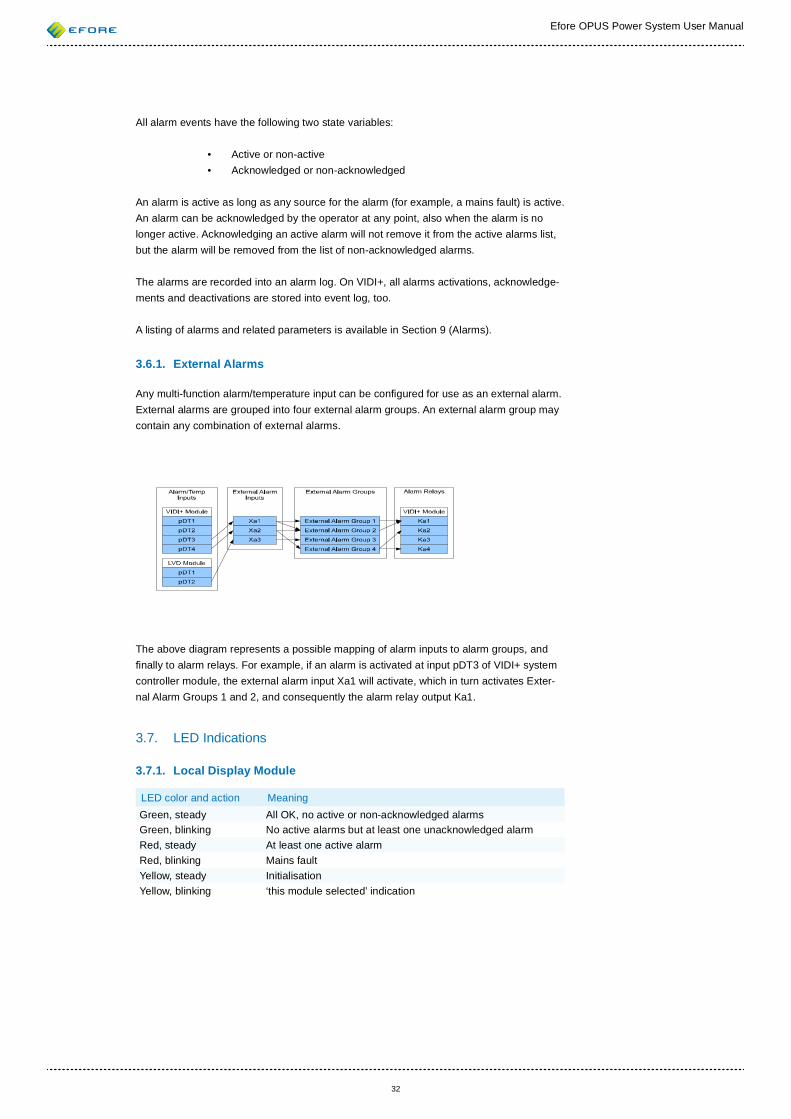
3.6.1. External Alarms
Any multi-function alarm/temperature input can be con gured for use as an external alarm. External alarms are grouped into four external alarm groups. An external alarm group may contain any combination of external alarms.
The above diagram represents a possible mapping of alarm inputs to alarm groups, and nally to alarm relays. For example, if an alarm is activated at input pDT3 of VIDI+ system controller module, the external alarm input Xa1 will activate, which in turn activates Exter-nal Alarm Groups 1 and 2, and consequently the alarm relay output Ka1.
3.7. LED Indications
3.7.1. Local Display Module
LED color and action MeaningGreen, steady All OK, no active or non-acknowledged alarmsGreen, blinking No active alarms but at least one unacknowledged alarmRed, steady At least one active alarmRed, blinking Mains faultYellow, steady InitialisationYellow, blinking ‘this module selected’ indication
Efore OPUS Power System User Manual
33
3.7.2. Recti er
LED color and action MeaningGreen, steady All OKGreen, blinking Communication errorRed, steady Fatal error, service needed:
Memory/parameter errorFuse faultDC faultFast DC over voltage protection (FOV)Other permanent error preventing recti er operation
Red, blinking Temporary failure:Mains faultOver temperatureSelective DC over voltage protection (SOV)DC undervoltage alarmOther temporary error
Yellow, steady Test modeYellow, blinking LED test
3.7.3. LVD Module
LED color and action MeaningGreen, steady All OK. Autonomous mode on or master presentGreen, blinking Initiliasation, communication error with a master controller and
autonomous mode not onRed, steady Fatal error, device must be replacedRed, blinking Contactor fault or over currentRed, one blink Boot-up LED testYellow, steady Test modeYellow, blinking LED test or ‘this module selected’ indication
3.7.4. BM Module
LED color and action MeaningGreen, steady All OKGreen, blinking Initiliasation, communication error with a master controllerRed, steady Fatal error, device must be replacedRed, blinking At least one of the con gured block measurements have low
voltageRed, one blink Boot-up LED testYellow, steady Test modeYellow, blinking LED test or ‘this module selected’ indication
3.7.5. SAM Module
LED color and action MeaningGreen, steady All OKGreen, blinking Initiliasation, communication error with a master controllerRed, steady Fatal error, device must be replacedRed, blinking NoneRed, one blink Boot-up LED testYellow, steady Test modeYellow, blinking LED test or ‘this module selected’ indication
LED indications of the EIM inverter and EBPU bypass modules are decriped in their user manuals.
Efore OPUS Power System User Manual
34
4. LOCAL USER INTERFACE
4.1. General
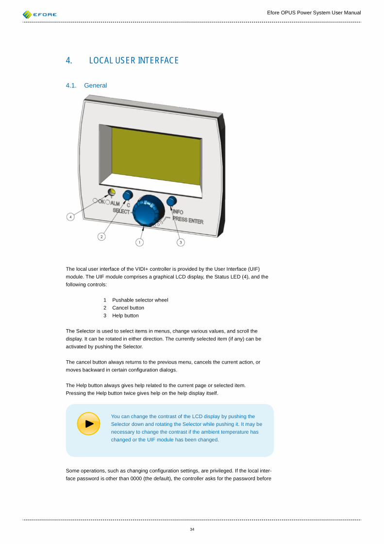
The local user interface of the VIDI+ controller is provided by the User Interface (UIF) module. The UIF module comprises a graphical LCD display, the Status LED (4), and the following controls:
1 Pushable selector wheel 2 Cancel button 3 Help button
The Selector is used to select items in menus, change various values, and scroll the display. It can be rotated in either direction. The currently selected item (if any) can be activated by pushing the Selector.
The cancel button always returns to the previous menu, cancels the current action, or moves backward in certain con guration dialogs.
The Help button always gives help related to the current page or selected item. Pressing the Help button twice gives help on the help display itself.
You can change the contrast of the LCD display by pushing the Selector down and rotating the Selector while pushing it. It may be necessary to change the contrast if the ambient temperature has changed or the UIF module has been changed.
Some operations, such as changing con guration settings, are privileged. If the local inter-face password is other than 0000 (the default), the controller asks for the password before
Efore OPUS Power System User Manual
35
allowing access to privileged operations. If the password is 0000, all password prompts are disabled for the local interface.
If you choose to use a password, it can be changed from the System Parameters menu. Please write the password down and store it in a safe place. A forgotten password can be recovered by the remote interface.
Refer to Section 4.11 (Menu Structure) for the structure of the local interface display menus.
4.2. The First Start-up In normal system shipments, the VIDI+ controller has been con gured by Efore at the fac-tory. However, should you receive an uncon gured VIDI+ controller, a few basic con gura-tion tasks need to be performed. VIDI+ will automatically ask for all the required informa-tion.
4.2.1. Base Parameters Dialog
There are three base parameters for which safe default values cann ot be assum ed.
These are:• Voltage Version • Nominal Current of System • Nominal Battery Capacity
If these parameters are not set, the Base Parameters Dialog will appear on the local inter-face. The dialog asks the user to set valid values for each of these parameters. After that, default values are assigned for all other parameters. The default value of many parameters depends on the three base parameters as described in Section 3.1 (Parameter System).
After setting of the base parameters (and the module/device con guration that will follow the Base Parameters Dialog), you should check that all important parameters are set as you want.
4.2.2. New Modules Dialog
If there are new modules installed in the system that do not require con guration, the New Modules Dialog will appear. Currently, UIF and AB are the only such modules. This dialog can be dismissed by pressing the Selector or the Cancel button.
4.2.3. Uncon gured Modules Dialog
The Uncon gured Modules Dialog will appear if there are new modules installed in the system and VIDI+ cannot con gure them automatically.
It should be noted that all device-speci c con gurations are stored in both the controller module and the modules containing the devices. For example, the Mains Phase attribute of the MRC recti er is stored both in the recti er itself and in the VIDI+ controller module. If the controller module needs to be replaced, the new controller module will load the device- or module-speci c con gurations from the modules. However, because the new controller cannot be sure whether the module con guration is actually correct (you could be moving the module in from another system), the Uncon gured Modules Dialog will prompt for its con guration.
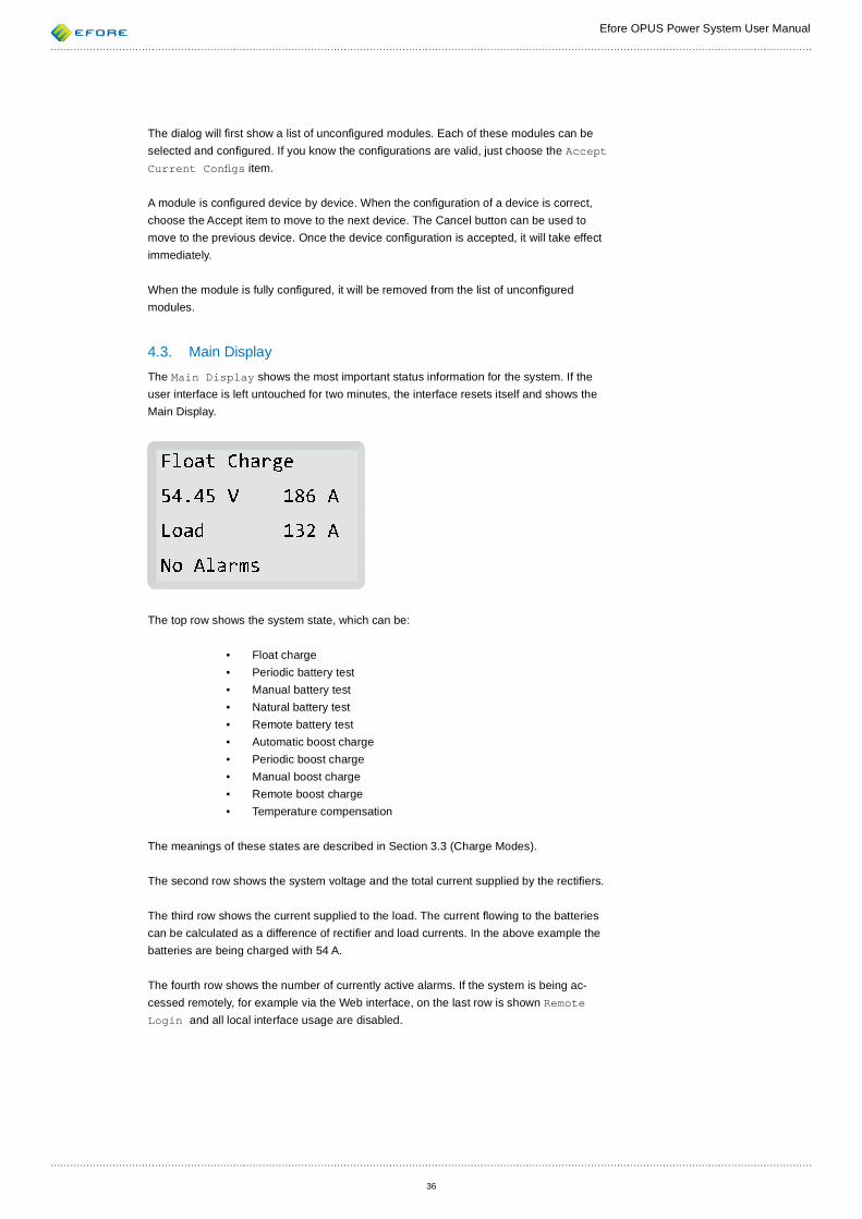
Efore OPUS Power System User Manual
36
The dialog will rst show a list of uncon gured modules. Each of these modules can be selected and con gured. If you know the con gurations are valid, just choose the Accept Current Con gs item.
A module is con gured device by device. When the con guration of a device is correct, choose the Accept item to move to the next device. The Cancel button can be used to move to the previous device. Once the device con guration is accepted, it will take effect immediately.
When the module is fully con gured, it will be removed from the list of uncon gured modules.
4.3. Main Display The Main Display shows the most important status information for the system. If the user interface is left untouched for two minutes, the interface resets itself and shows the Main Display.
The top row shows the system state, which can be:
• Float charge• Periodic battery test• Manual battery test• Natural battery test• Remote battery test• Automatic boost charge• Periodic boost charge• Manual boost charge• Remote boost charge• Temperature compensation
The meanings of these states are described in Section 3.3 (Charge Modes).
The second row shows the system voltage and the total current supplied by the recti ers.
The third row shows the current supplied to the load. The current owing to the batteries can be calculated as a difference of recti er and load currents. In the above example the batteries are being charged with 54 A.
The fourth row shows the number of currently active alarms. If the system is being ac-cessed remotely, for example via the Web interface, on the last row is shown Remote Login and all local interface usage are disabled.
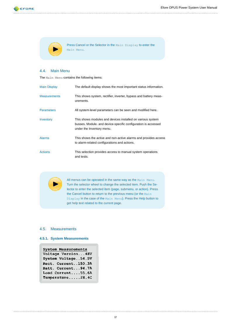
Efore OPUS Power System User Manual
37
Press Cancel or the Selector in the Main Display to enter the Main Menu.
4.4. Main Menu The Main Menu contains the following items:
Main Display The default display shows the most important status information.
Measurements This shows system, recti er, inverter, bypass and battery meas-urements.
Parameters All system-level parameters can be seen and modi ed here.
Inventory This shows modules and devices installed on various system busses. Module- and device-speci c con guration is accessed under the Inventory menu.
Alarms This shows the active and non-active alarms and provides access to alarm-related con gurations and actions.
Actions This selection provides access to manual system operations and tests.
All menus can be operated in the same way as the Main Menu. Turn the selector wheel to change the selected item. Push the Se-lector to enter the selected item (page, submenu, or action). Press the Cancel button to return to the previous menu (or the Main Display in the case of the Main Menu). Press the Help button to get help text related to the current page.
4.5. Measurements
4.5.1. System Measurements

Efore OPUS Power System User Manual
38
Voltage Version is the nominal voltage of the system. System Voltage is the meas-ured system voltage. Rect. Current is the total current supplied by the recti ers.
Batt. Current is the total battery current, which is positive when batteries are being charged and negative when batteries are being discharged. If there is no battery current shunt resistor installed and con gured, the battery current is shown as zero. If there are multiple battery current shunt resistors available, the reading is the sum of the measured currents.
Load Current is always calculated by subtracting the battery current from the recti er current. The calculation does not take into account the marginal current consumption of the system modules. Load current measurement devices do not affect this reading.
Temperature is the measured ambient temperature of the system. At least one ambient temperature sensor has to be enabled for a valid reading to be obtained. If multiple ambi-ent temperature sensors are con gured, the highest reading is used and shown here.
The System Measurements page can be reached from Main Menu • Measurements • System.
4.5.2. Battery Block Measurements
Max Temp indicates the temperature of the battery temperature sensor, or the temperature of the warmest-reading battery temperature sensor if multiple battery temperature sensors are installed and con gured.
Total Current is the total battery current, positive when batteries are being charged and negative when batteries are being discharged. This measurement is also available from the System Measurements page.
Discharged is a reading indicating the amount of energy discharged from the batteries. It is always positive or zero. A value of zero means that the batteries are judged to be full.
The following line indicates the charge direction of the battery, which is either Charges, Discharges or In Stand-by. Normally a battery current shunt resistor is used to measure the battery current, and thus the charge direction. In stand-by means that battery current is so small that charge direction cannot be determined reliably. If there’s no battery current measurement available at all, the controller assumes that batteries are charged when there is no mains fault, and discharged when there is a mains fault.
Temperatures shows a list of functional battery temperature sensors and measurements on a separate page.
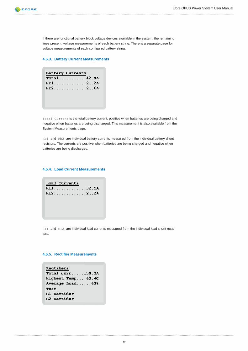
Efore OPUS Power System User Manual
39
If there are functional battery block voltage devices available in the system, the remaining lines present voltage measurements of each battery string. There is a separate page for voltage measurements of each con gured battery string.
4.5.3. Battery Current Measurements
Total Current is the total battery current, positive when batteries are being charged and negative when batteries are being discharged. This measurement is also available from the System Measurements page.
Rb1 and Rb2 are individual battery currents measured from the individual battery shunt resistors. The currents are positive when batteries are being charged and negative when batteries are being discharged.
4.5.4. Load Current Measurements
Rl1 and Rl2 are individual load currents measured from the individual load shunt resis-tors.
4.5.5. Recti er Measurements
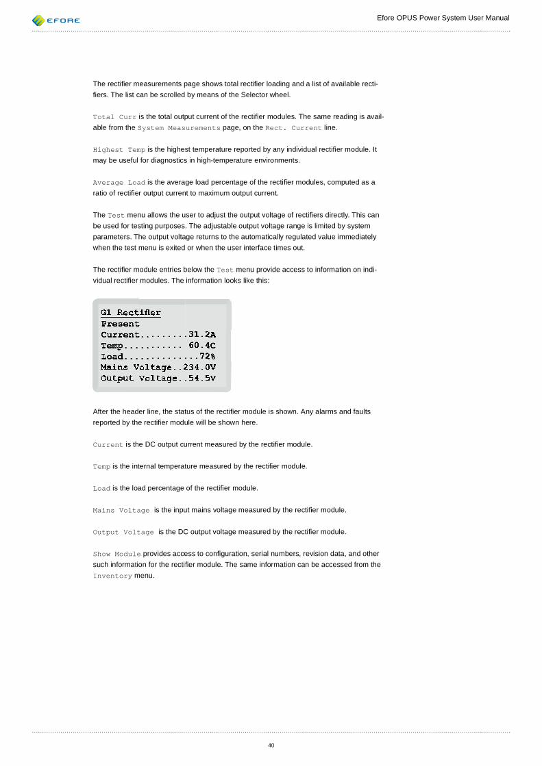
Efore OPUS Power System User Manual
40
The recti er measurements page shows total recti er loading and a list of available recti- ers. The list can be scrolled by means of the Selector wheel.
Total Curr is the total output current of the recti er modules. The same reading is avail-able from the System Measurements page, on the Rect. Current line.
Highest Temp is the highest temperature reported by any individual recti er module. It may be useful for diagnostics in high-temperature environments.
Average Load is the average load percentage of the recti er modules, computed as a ratio of recti er output current to maximum output current.
The Test menu allows the user to adjust the output voltage of recti ers directly. This can be used for testing purposes. The adjustable output voltage range is limited by system parameters. The output voltage returns to the automatically regulated value immediately when the test menu is exited or when the user interface times out.
The recti er module entries below the Test menu provide access to information on indi-vidual recti er modules. The information looks like this:
After the header line, the status of the recti er module is shown. Any alarms and faults reported by the recti er module will be shown here.
Current is the DC output current measured by the recti er module.
Temp is the internal temperature measured by the recti er module.
Load is the load percentage of the recti er module.
Mains Voltage is the input mains voltage measured by the recti er module.
Output Voltage is the DC output voltage measured by the recti er module.
Show Module provides access to con guration, serial numbers, revision data, and other such information for the recti er module. The same information can be accessed from the Inventory menu.
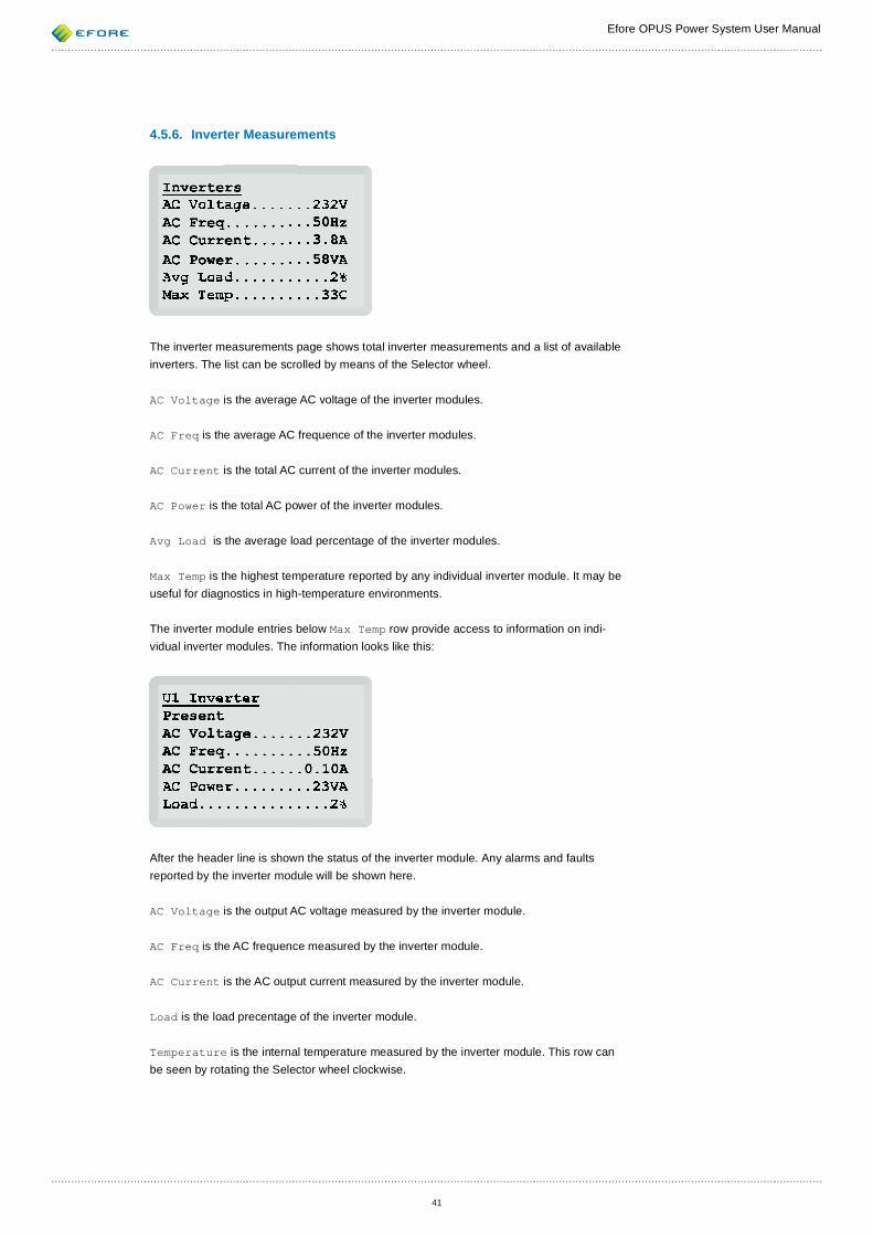
Efore OPUS Power System User Manual
41
4.5.6. Inverter Measurements
The inverter measurements page shows total inverter measurements and a list of available inverters. The list can be scrolled by means of the Selector wheel.
AC Voltage is the average AC voltage of the inverter modules.
AC Freq is the average AC frequence of the inverter modules.
AC Current is the total AC current of the inverter modules.
AC Power is the total AC power of the inverter modules.
Avg Load is the average load percentage of the inverter modules.
Max Temp is the highest temperature reported by any individual inverter module. It may be useful for diagnostics in high-temperature environments.
The inverter module entries below Max Temp row provide access to information on indi-vidual inverter modules. The information looks like this:
After the header line is shown the status of the inverter module. Any alarms and faults reported by the inverter module will be shown here.
AC Voltage is the output AC voltage measured by the inverter module.
AC Freq is the AC frequence measured by the inverter module.
AC Current is the AC output current measured by the inverter module.
Load is the load precentage of the inverter module.
Temperature is the internal temperature measured by the inverter module. This row can be seen by rotating the Selector wheel clockwise.
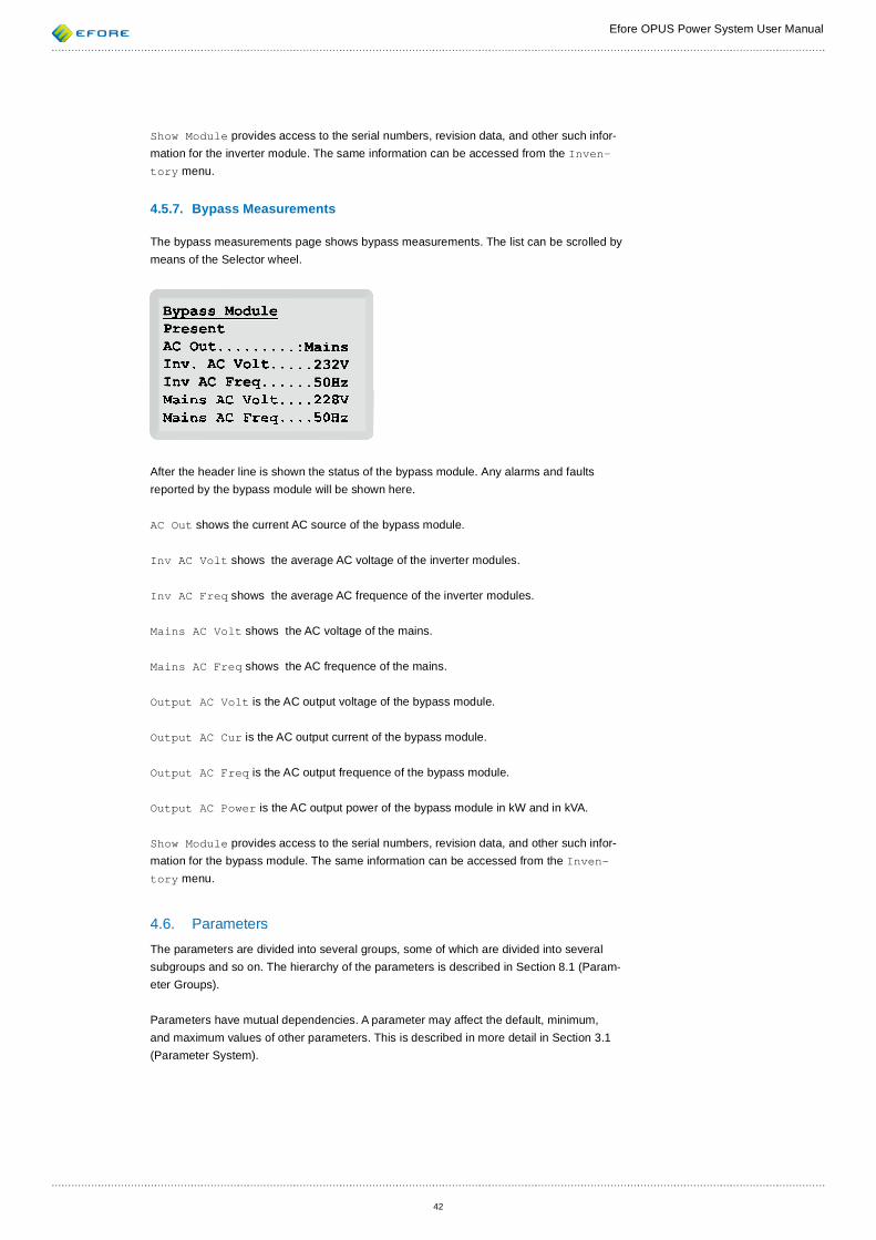
Efore OPUS Power System User Manual
42
Show Module provides access to the serial numbers, revision data, and other such infor-mation for the inverter module. The same information can be accessed from the Inven-tory menu.
4.5.7. Bypass Measurements
The bypass measurements page shows bypass measurements. The list can be scrolled by means of the Selector wheel.
After the header line is shown the status of the bypass module. Any alarms and faults reported by the bypass module will be shown here.
AC Out shows the current AC source of the bypass module.
Inv AC Volt shows the average AC voltage of the inverter modules.
Inv AC Freq shows the average AC frequence of the inverter modules.
Mains AC Volt shows the AC voltage of the mains.
Mains AC Freq shows the AC frequence of the mains.
Output AC Volt is the AC output voltage of the bypass module.
Output AC Cur is the AC output current of the bypass module.
Output AC Freq is the AC output frequence of the bypass module.
Output AC Power is the AC output power of the bypass module in kW and in kVA.
Show Module provides access to the serial numbers, revision data, and other such infor-mation for the bypass module. The same information can be accessed from the Inven-tory menu.
4.6. Parameters The parameters are divided into several groups, some of which are divided into several subgroups and so on. The hierarchy of the parameters is described in Section 8.1 (Param-eter Groups).
Parameters have mutual dependencies. A parameter may affect the default, minimum, and maximum values of other parameters. This is described in more detail in Section 3.1 (Parameter System).

Efore OPUS Power System User Manual
43
4.6.1. Parameter Page
There is a parameter page for each parameter. From a parameter page, you can view the current value of the parameter and modify that value. If a local interface password is set, modifying the value requires entry of the password. The password itself is a system parameter.
The following is an example of the parameter page for the Float Charge Voltage parameter.
The title line shows the name of the parameter.
The second line shows the current value of the parameter. If the value is blinking, this indi-cates that the value can be changed by turning the selector wheel. If the value is not blink-ing, editing can be started by selecting the value. However, if the local interface password is required but not yet entered, it must be entered before the value can be changed.
After the correct value has been set, editing can be nished by pushing the Selector. To con rm the parameter change, select the Accept item. If the parameter has dependen-cies, the depending parameter will be shown after Accept is selected. An informational message about parameter dependencies will be shown before the rst depending param-eter.
To cancel editing of a parameter, or to exit the parameter page, press the Cancel button. If you are on a parameter page for a dependent parameter, pressing the Cancel button will return you the previous parameter page.
If the parameter has a valid previous value, the Old line shows this value. It can be re-stored by selecting the Old item.
The default value of the parameter is indicated by the Default line. The default value can be used by selecting the Default item.
To see help text related to a parameter, press the Help button.
4.6.2. Device List Parameters
There is a special parameter type called a device list. Device list parameters allow selec-tion of any combination of related devices. The device list parameters are used for
• Selection of alarm relays selection for each alarm • Alarm inputs’ selection for external alarm groups
The device list selection screen can look like this:
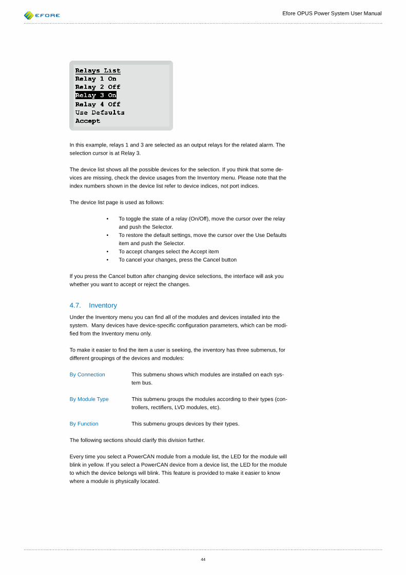
Efore OPUS Power System User Manual
44
In this example, relays 1 and 3 are selected as an output relays for the related alarm. The selection cursor is at Relay 3.
The device list shows all the possible devices for the selection. If you think that some de-vices are missing, check the device usages from the Inventory menu. Please note that the index numbers shown in the device list refer to device indices, not port indices.
The device list page is used as follows:
• To toggle the state of a relay (On/Off), move the cursor over the relay and push the Selector.
• To restore the default settings, move the cursor over the Use Defaults item and push the Selector.
• To accept changes select the Accept item• To cancel your changes, press the Cancel button
If you press the Cancel button after changing device selections, the interface will ask you whether you want to accept or reject the changes.
4.7. Inventory Under the Inventory menu you can nd all of the modules and devices installed into the system. Many devices have device-speci c con guration parameters, which can be modi- ed from the Inventory menu only.
To make it easier to nd the item a user is seeking, the inventory has three submenus, for different groupings of the devices and modules:
By Connection This submenu shows which modules are installed on each sys-tem bus.
By Module Type This submenu groups the modules according to their types (con-trollers, recti ers, LVD modules, etc).
By Function This submenu groups devices by their types.
The following sections should clarify this division further.
Every time you select a PowerCAN module from a module list, the LED for the module will blink in yellow. If you select a PowerCAN device from a device list, the LED for the module to which the device belongs will blink. This feature is provided to make it easier to know where a module is physically located.
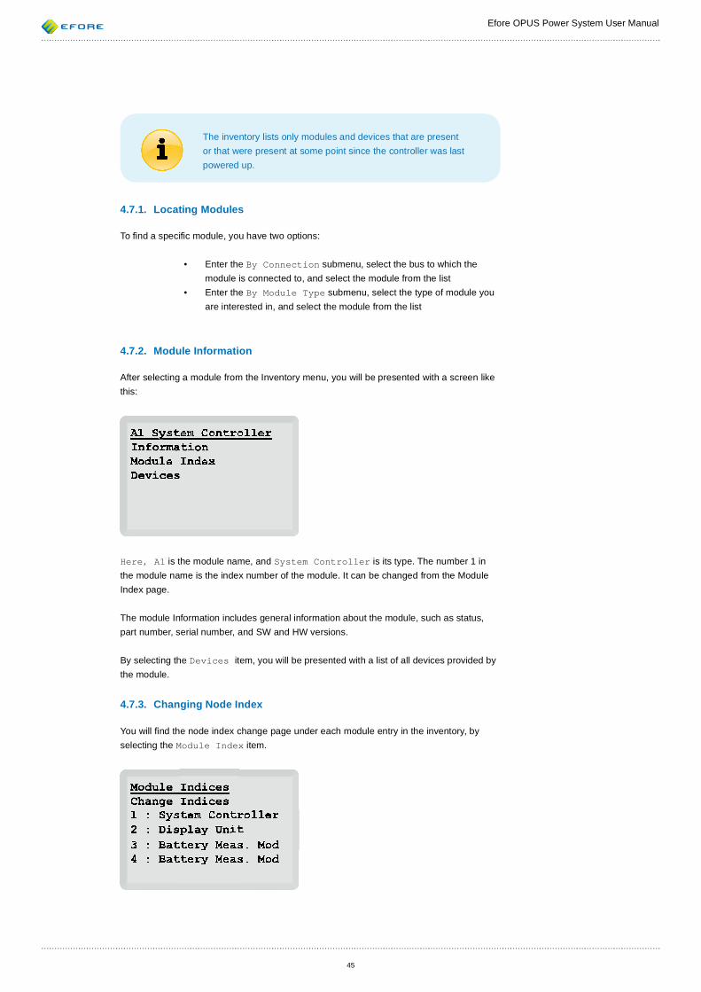
Efore OPUS Power System User Manual
45
The inventory lists only modules and devices that are present or that were present at some point since the controller was last powered up.
4.7.1. Locating Modules
To nd a speci c module, you have two options:
• Enter the By Connection submenu, select the bus to which the module is connected to, and select the module from the list
• Enter the By Module Type submenu, select the type of module you are interested in, and select the module from the list
4.7.2. Module Information
After selecting a module from the Inventory menu, you will be presented with a screen like this:
Here, A1 is the module name, and System Controller is its type. The number 1 in the module name is the index number of the module. It can be changed from the Module Index page.
The module Information includes general information about the module, such as status, part number, serial number, and SW and HW versions.
By selecting the Devices item, you will be presented with a list of all devices provided by the module.
4.7.3. Changing Node Index
You will nd the node index change page under each module entry in the inventory, by selecting the Module Index item.
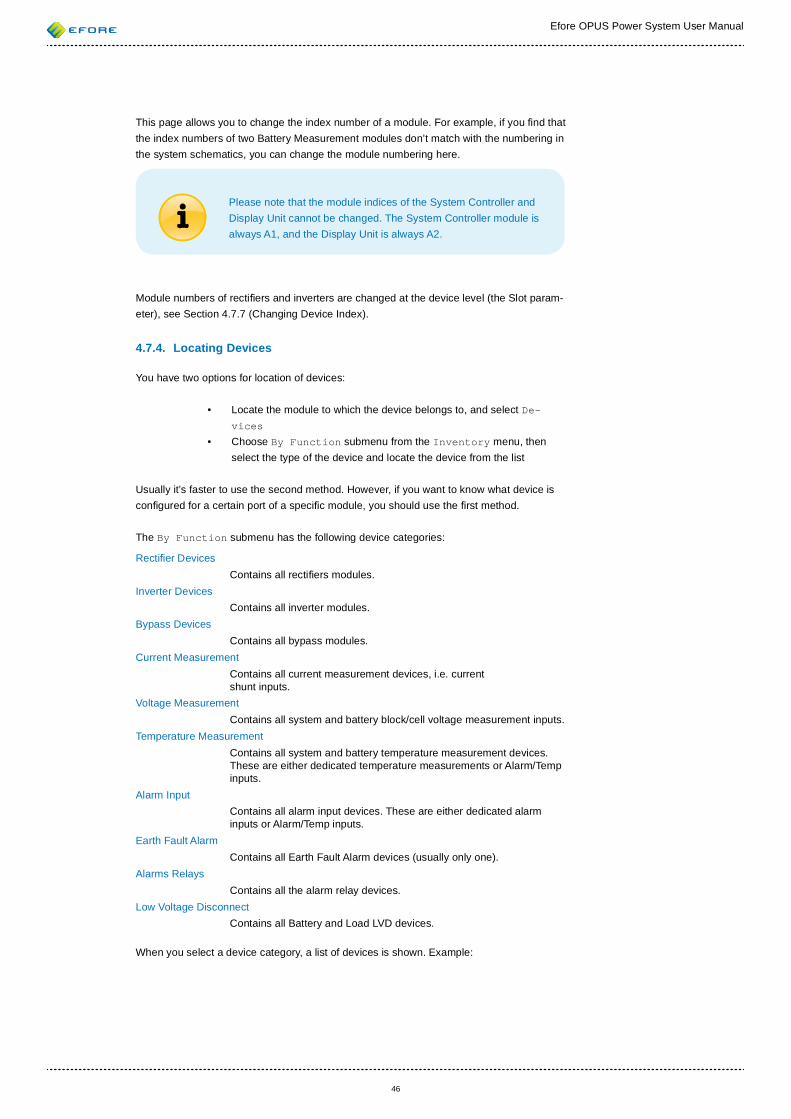
Efore OPUS Power System User Manual
46
This page allows you to change the index number of a module. For example, if you nd that the index numbers of two Battery Measurement modules don’t match with the numbering in the system schematics, you can change the module numbering here.
Please note that the module indices of the System Controller and Display Unit cannot be changed. The System Controller module is always A1, and the Display Unit is always A2.
Module numbers of recti ers and inverters are changed at the device level (the Slot param-eter), see Section 4.7.7 (Changing Device Index).
4.7.4. Locating Devices
You have two options for location of devices:
• Locate the module to which the device belongs to, and select De-vices
• Choose By Function submenu from the Inventory menu, then select the type of the device and locate the device from the list
Usually it’s faster to use the second method. However, if you want to know what device is con gured for a certain port of a speci c module, you should use the rst method.
The By Function submenu has the following device categories:
Recti er Devices Contains all recti ers modules.Inverter Devices Contains all inverter modules.Bypass Devices Contains all bypass modules.Current Measurement Contains all current measurement devices, i.e. current
shunt inputs. Voltage Measurement Contains all system and battery block/cell voltage measurement inputs. Temperature Measurement Contains all system and battery temperature measurement devices.
These are either dedicated temperature measurements or Alarm/Temp inputs.
Alarm Input Contains all alarm input devices. These are either dedicated alarm
inputs or Alarm/Temp inputs. Earth Fault Alarm Contains all Earth Fault Alarm devices (usually only one).Alarms Relays Contains all the alarm relay devices. Low Voltage Disconnect Contains all Battery and Load LVD devices.
When you select a device category, a list of devices is shown. Example:
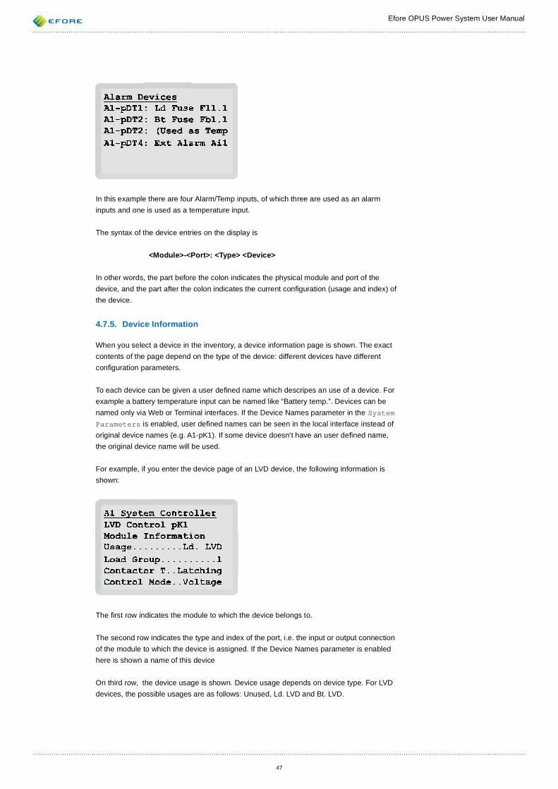
Efore OPUS Power System User Manual
47
In this example there are four Alarm/Temp inputs, of which three are used as an alarm inputs and one is used as a temperature input.
The syntax of the device entries on the display is
<Module>-<Port>: <Type> <Device>
In other words, the part before the colon indicates the physical module and port of the device, and the part after the colon indicates the current con guration (usage and index) of the device.
4.7.5. Device Information
When you select a device in the inventory, a device information page is shown. The exact contents of the page depend on the type of the device: different devices have different con guration parameters.
To each device can be given a user de ned name which descripes an use of a device. For example a battery temperature input can be named like “Battery temp.”. Devices can be named only via Web or Terminal interfaces. If the Device Names parameter in the System Parameters is enabled, user de ned names can be seen in the local interface instead of original device names (e.g. A1-pK1). If some device doesn’t have an user de ned name, the original device name will be used.
For example, if you enter the device page of an LVD device, the following information is shown:
The rst row indicates the module to which the device belongs to.
The second row indicates the type and index of the port, i.e. the input or output connection of the module to which the device is assigned. If the Device Names parameter is enabled here is shown a name of this device
On third row, the device usage is shown. Device usage depends on device type. For LVD devices, the possible usages are as follows: Unused, Ld. LVD and Bt. LVD.
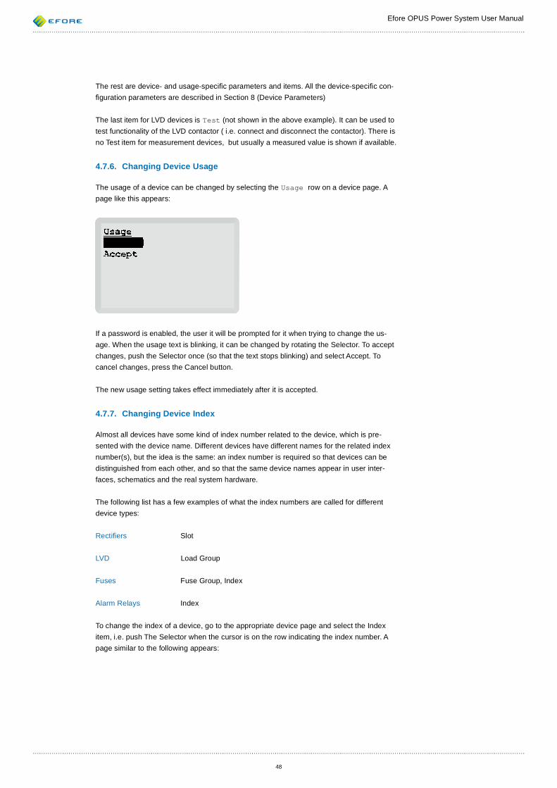
Efore OPUS Power System User Manual
48
The rest are device- and usage-speci c parameters and items. All the device-speci c con- guration parameters are described in Section 8 (Device Parameters)
The last item for LVD devices is Test (not shown in the above example). It can be used to test functionality of the LVD contactor ( i.e. connect and disconnect the contactor). There is no Test item for measurement devices, but usually a measured value is shown if available.
4.7.6. Changing Device Usage
The usage of a device can be changed by selecting the Usage row on a device page. A page like this appears:
If a password is enabled, the user it will be prompted for it when trying to change the us-age. When the usage text is blinking, it can be changed by rotating the Selector. To accept changes, push the Selector once (so that the text stops blinking) and select Accept. To cancel changes, press the Cancel button.
The new usage setting takes effect immediately after it is accepted.
4.7.7. Changing Device Index
Almost all devices have some kind of index number related to the device, which is pre-sented with the device name. Different devices have different names for the related index number(s), but the idea is the same: an index number is required so that devices can be distinguished from each other, and so that the same device names appear in user inter-faces, schematics and the real system hardware.
The following list has a few examples of what the index numbers are called for different device types:
Recti ers Slot
LVD Load Group
Fuses Fuse Group, Index
Alarm Relays Index
To change the index of a device, go to the appropriate device page and select the Index item, i.e. push The Selector when the cursor is on the row indicating the index number. A page similar to the following appears:
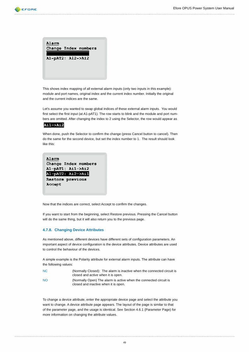
Efore OPUS Power System User Manual
49
This shows index mapping of all external alarm inputs (only two inputs in this example): module and port names, original index and the current index number. Initially the original and the current indices are the same.
Let’s assume you wanted to swap global indices of these external alarm inputs. You would rst select the rst input (at A1-pAT1). The row starts to blink and the module and port num-bers are omitted. After changing the index to 2 using the Selector, the row would appear as
Ai1->Ai2
When done, push the Selector to con rm the change (press Cancel button to cancel). Then do the same for the second device, but set the index number to 1. The result should look like this:
Now that the indices are correct, select Accept to con rm the changes.
If you want to start from the beginning, select Restore previous. Pressing the Cancel button will do the same thing, but it will also return you to the previous page.
4.7.8. Changing Device Attributes
As mentioned above, different devices have different sets of con guration parameters. An important aspect of device con guration is the device attributes. Device attributes are used to control the behaviour of the devices.
A simple example is the Polarity attribute for external alarm inputs. The attribute can have the following values:
NC (Normally Closed): The alarm is inactive when the connected circuit is closed and active when it is open.
NO (Normally Open) The alarm is active when the connected circuit is closed and inactive when it is open.
To change a device attribute, enter the appropriate device page and select the attribute you want to change. A device attribute page appears. The layout of the page is similar to that of the parameter page, and the usage is identical. See Section 4.6.1 (Parameter Page) for more information on changing the attribute values.
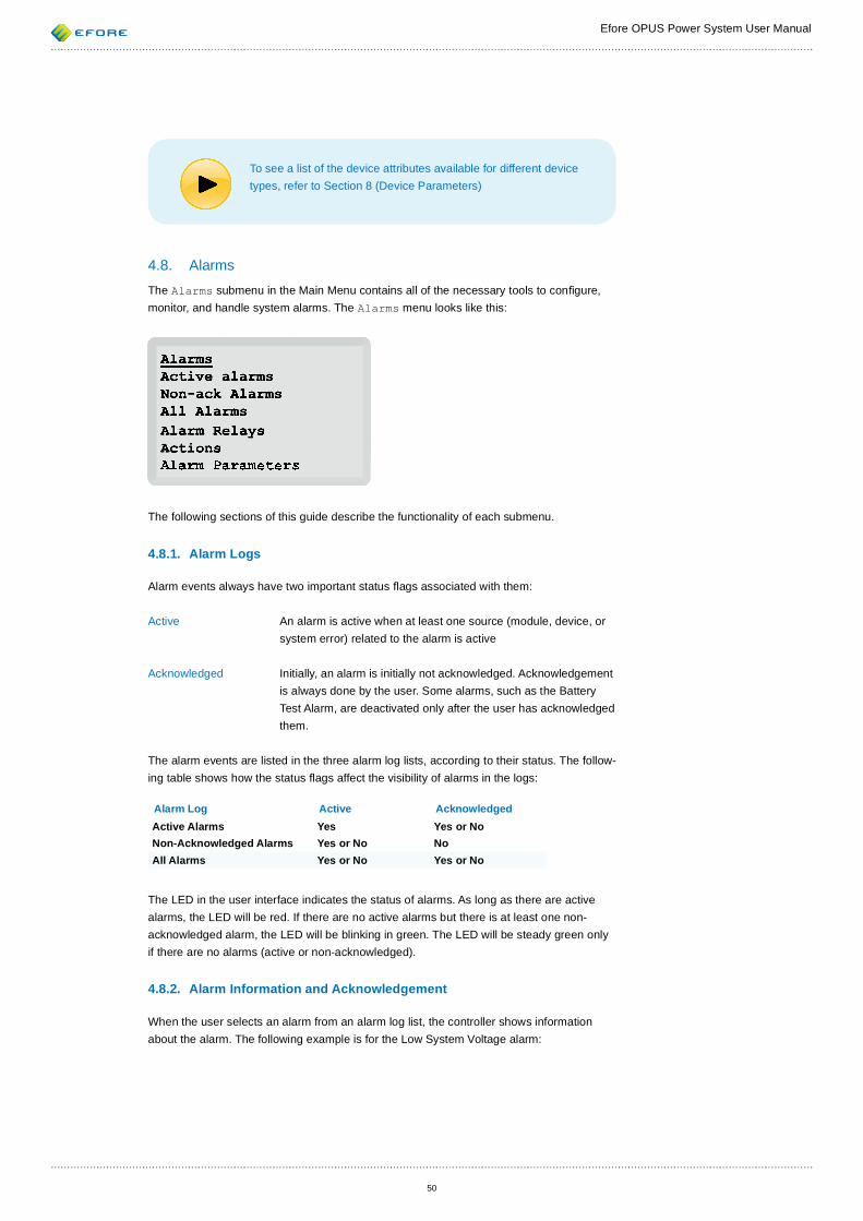
Efore OPUS Power System User Manual
50
To see a list of the device attributes available for different device types, refer to Section 8 (Device Parameters)
4.8. AlarmsThe Alarms submenu in the Main Menu contains all of the necessary tools to con gure, monitor, and handle system alarms. The Alarms menu looks like this:
The following sections of this guide describe the functionality of each submenu.
4.8.1. Alarm Logs
Alarm events always have two important status ags associated with them:
Active An alarm is active when at least one source (module, device, or system error) related to the alarm is active
Acknowledged Initially, an alarm is initially not acknowledged. Acknowledgement is always done by the user. Some alarms, such as the Battery Test Alarm, are deactivated only after the user has acknowledged them.
The alarm events are listed in the three alarm log lists, according to their status. The follow-ing table shows how the status ags affect the visibility of alarms in the logs:
Alarm Log Active AcknowledgedActive Alarms Yes Yes or NoNon-Acknowledged Alarms Yes or No NoAll Alarms Yes or No Yes or No
The LED in the user interface indicates the status of alarms. As long as there are active alarms, the LED will be red. If there are no active alarms but there is at least one non-acknowledged alarm, the LED will be blinking in green. The LED will be steady green only if there are no alarms (active or non-acknowledged).
4.8.2. Alarm Information and Acknowledgement
When the user selects an alarm from an alarm log list, the controller shows information about the alarm. The following example is for the Low System Voltage alarm:
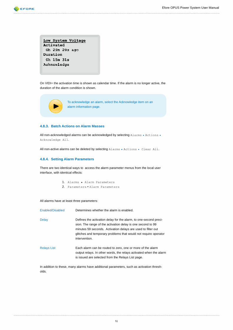
Efore OPUS Power System User Manual
51
On VIDI+ the activation time is shown as calendar time. If the alarm is no longer active, the duration of the alarm condition is shown.
To acknowledge an alarm, select the Acknowledge item on an alarm information page.
4.8.3. Batch Actions on Alarm Masses
All non-acknowledged alarms can be acknowledged by selecting Alarms • Actions • Acknowledge All.
All non-active alarms can be deleted by selecting Alarms • Actions • Clear All.
4.8.4. Setting Alarm Parameters
There are two identical ways to access the alarm parameter menus from the local user interface, with identical effects:
1. Alarms • Alarm Parameters2. Parameters • Alarm Parameters
All alarms have at least three parameters:
Enabled/Disabled Determines whether the alarm is enabled.
Delay De nes the activation delay for the alarm, to one-second preci-sion. The range of the activation delay is one second to 99 minutes 59 seconds. Activation delays are used to lter out glitches and temporary problems that would not require operator intervention.
Relays List Each alarm can be routed to zero, one or more of the alarm output relays. In other words, the relays activated when the alarm is issued are selected from the Relays List page.
In addition to these, many alarms have additional parameters, such as activation thresh-olds.
Efore OPUS Power System User Manual
52
4.8.5. Con guring Alarm Relays
As described in the previous section, the alarm relays related to an alarm are con gured from the alarm’s parameters page. The instructions for working with a device list parameter are found in Section 4.6.2 (Device List Parameters).
To see which alarms are assigned to a certain relay, select the relay from the Alarms • Alarm Relays list. A page listing all the assigned alarms (if any) appears.
To test the operation of alarm relays without making any alarms active, enter the Actions • Test Devices • Alarm Relays page.
4.9. ActionsYou can access most of the manual system operations and commands under the Actions menu.
4.9.1. Device Tests
The Device Tests page allows a user to test LVD contactors and alarm relays. After the state of a device is changed manually, it will remain under manual control until the user leaves the test page or a display time-out (about two minutes) occurs.
4.9.2. Manual Boost Charging
Boost charging allows faster charging of the batteries to full capacity. Refer to Section 3.3.2 (Boost Charge) for more information on boost charging.
Manual boost charging can be started from Actions • Boost Charge • Start Man-ual Boost Charge. If a boost charge mode is already active, it can be stopped here.
Certain alarms prevent the automatic and periodic boost charge modes from starting. These alarms must be acknowledged before manual boost charging can be started. How-ever, the controller will inform the user of any such non-acknowledged alarms in the event that manual boost charging is attempted.
The maximum time limit for manual boost charging can be set from the Actions • Boost Charge • Con gure Parameters • Manual Boost Charge menu. Please note that the same parameters can be accessed from the Parameters • Charge Pa-rameters menu.
4.9.3. Manual Battery Tests
Starting and stopping of manual battery tests is similar to that of manual boost charging described in the previous section. Manual battery test operations can be accessed from the Actions • Battery Tests menu.
Refer to Section 3.3.4 (Battery Tests) for more information on battery tests in general.
4.9.4. Factory Parameters
Factory parameters are saved in the system after initial con guration of the system at the factory. The factory parameters include the correct voltage version, system nominal current and other parameters as requested in the original system order. Any parameter changes made by the end customer are usually not included in the factory parameters, unless fac-tory parameters have been overwritten by the customer.
Efore OPUS Power System User Manual
53
Factory parameters do not contain, or affect, any device-speci c or module-speci c con- gurations.
If you suspect that the integrity of the system parameters has been compromised, you can restore the factory parameters from the Actions • Load Factory Params menu. This operation requires entering the system password if it is not the default. After restoring the factory parameters, please check the correctness of all the important parameters.
Please note that restoration of the factory parameters cannot be undone.
It is also possible to save the current state of parameters as factory parameters. This can be accomplished from Actions • Save Factory Params menu, but the Expert Mode parameter in the System Parameters must be enabled for this menu to be visible. After the factory parameters have been rewritten, the original factory parameters will be lost.
4.9.5. Restarting Controller
In some rare cases it may be necessary to restart the system controller. The controller’s restarting doesn’t affect to the system parameter or decive settings.
Restarting the controller does not interrupt the power supply from the recti ers. However, in use of a non-latching LVD contactor connected directly to the system controller module, the contactor will be disconnected for a short time. Also the alarm relays will be activated for a while.
The controller can be restarted from Actions • Restart Controller.
4.9.6. Reset Battery Discharge
If the battery discharge log is wanted to be cleared, it can be done by selecting Actions • Clear Batt. Disc.
4.9.7. Clear All Data
All system data can be cleared from the Actions • Clear All Data menu. This clears all parameters, device con gurations and log data from all system modules. After this ac-tion the VIDI+ controller asks user to set system parameters and device con gurations.
Efore OPUS Power System User Manual
54
4.10. Common Tasks
This section contains instructions for accomplishing some commonly required tasks.
4.10.1. Setting the Low Voltage Alarm Limit
1. Go to the Parameters • Alarm Parameters • System Alarms • Low System Voltage • Low SysV Limit page
2. Enter the new voltage limit 3. Select Accept 4. You are Done!
4.10.2. Setting LVD Pickup and Disconnect Parameters
There are multiple sets of LVD parameters:
Load LVD Defaults De nes the default parameters for all load LVD devices. When you
change a default parameter, the controller will prompt you on chang-ing the corresponding parameter for all load LVD devices to the new default.
Battery LVD Defaults Similar to Load LVD Defaults, but applies to all battery LVDs. Device-Speci c Each LVD device has its own set of parameters which can be set indi-
vidually.
Usually, it is recommended to change the device-speci c LVD parameters directly:
1. Locate the LVD device - for example, go to Inventory • By Function • Low Voltage Disconnect and select the correct LVD device
2. Select the parameter you want to change 3. Enter the new value4. Select Accept5. You are Done
4.10.3. Setting the Battery Charge Current Limit
See Section 3.3.3 (Battery Charge Current Limiting) for description of battery charge cur-rent limitation feature.
To enable and set the system-wide charge current limit:
1. Enter the Parameters • Charge Parameters • Charge Cur-rent Control menu
2. Set the Charge Current Limit parameter to the correct value3. Make sure the Enabled/Disabled parameter is set to Enabled
Efore OPUS Power System User Manual
55
To set the charge current limit for a speci c current measurement device (i.e. to limit the charge current of a speci c battery string):
1. Locate the battery current measurement device from the Inventory, for example, go to Inventory • By Function • Current Meas-urement and select the correct device from the list
2. Select the Charge Limit parameter and push the Selector on it3. Specify the new value and select Accept
Please note that for device-speci c charge current limitation to work, the system-wide charge current limiting must have been enabled in the system charge parameters.
4.10.4. Changing Start Times of Periodic Tasks
Periodic boost charge and periodic battery testing can be con gured to start a certain number of times per year. These numbers can be changed in the parameters menu.
By contrast, the next start time of these operations can be checked and changed from the actions menu: Actions • Boost Charge • Periodic Start Time for periodic boost charge and Actions • Battery Tests • Periodic Start Time for peri-odic battery test.
4.10.5. Setting the Earth Fault Detection Threshold
Earth fault detection works by measuring leak resistance from the system DC bus bar (both positive and negative) to protective earth of the system (the PE ground). If the leak resist-ance is below the selected alarm threshold, the Earth Fault alarm is activated. The alarm shows whether a leakage is between the system plus (Earth Fault: +Rail) or minus (Earth Fault: -Rail) bus par and the PE ground.
The activation delay time for the Earth Fault alarm should be at least 10 seconds. If a smaller delay is used, the risk of false alarms during system voltage transitions increases.
1. Enter the Parameters • Alarm Parameters • System Alarms • Earth Fault menu.
2. Make sure the Enabled/Disabled parameter is set to Enabled.3. Check the alarm activation Delay time.4. Select the Threshold parameter and choose a leak resistance thresh-
old: 100 kOhm, 500 kOhm or 1 MOhm.
It is recommended to test the Earth Fault alarm after any changes to the alarm’s parameters. Testing can be done by connecting a properly selected resistor between a DC bus bar ( rst positive and then negative pole, but not both at the same time) and PE. How-ever, there can be a risk of electric shock when one peforms such a test, so proper electrical work procedures must be followed!
Efore OPUS Power System User Manual
56
For the Earth Fault alarm to function properly, the VIDI+ system control module must have an I/O card installed (a factory-installed option), and an Earth Fault Alarm device must have been con g-ured and enabled. The device, if it is available, can be found via from Inventory • By Function • Earth Fault Alarm.
4.10.6. Removing Obsolete Modules from Inventory
As described in Section 3.2.4 (Inventory Limit) the inventory database of the VIDI+ control-ler contains both present and old (removed) modules.
It is recommended that, after permanently removing modules from the system, you free the internal resources allocated for those modules in the VIDI+ controller. This can be ac-complished from the inventory menu: Inventory • Remove Missing Modules. The operation removes information about all devices not currently present in the system.
If a module has been removed from a system but the Remove Missing Modules action has not been performed, the Communication Error alarm is active. By selecting this alarm can be seen more detailed information from the alarm source and the activation time. The alarm is not deactivated although it is acknowledged. To deactivate the alarm perform the action Remove Missing Modules.
4.11. Menu Structure A diagram in the appendix A illustrates the local user interface menu hierarchy in a simpli- ed form. Dynamic menu structures have been omitted. Parameter and alarm parameter submenus are presented in the appendices B and C
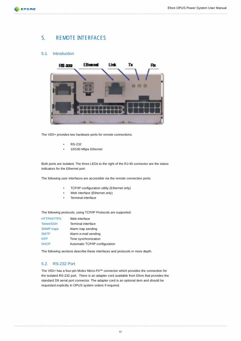
Efore OPUS Power System User Manual
57
5. REMOTE INTERFACES
5.1. Introduction
The VIDI+ provides two hardware ports for remote connections:
• RS-232• 10/100 Mbps Ethernet
Both ports are isolated. The three LEDs to the right of the RJ-45 connector are the status indicators for the Ethernet port.
The following user interfaces are accessible via the remote connection ports:
• TCP/IP con guration utility (Ethernet only)• Web interface (Ethernet only)• Terminal interface
The following protocols, using TCP/IP Protocols are supported:
HTTP/HTTPS Web interfaceTelnet/SSH Terminal interfaceSNMP traps Alarm trap sending SMTP Alarm e-mail sendingNTP Time synchronizationDHCP Automatic TCP/IP con guration
The following sections describe these interfaces and protocols in more depth.
5.2. RS-232 PortThe VIDi+ has a four-pin Molex Micro-Fit™ connector which provides the connection for the isolated RS-232 port. There is an adapter cord available from Efore that provides the standard D9 serial port connector. The adapter cord is an optional item and should be requested explicitly in OPUS system orders if required.
Efore OPUS Power System User Manual
58
The default communication settings for the RS-232 port are:
Baud rate 115200 bpsData bits 8Parity NoneStop bits 1Flow control Off
Baud rate, parity and stop bits settings are included in the VIDI+ communication pa-rameters group and can be modi ed. These parameters are accessible through all user interfaces.
The RS-232 port provides the same text-based user interface as the SSH and Telnet pro-tocols provide for the Ethernet connection. See Section 5.6 (Terminal Interface) for more information.
Most terminal program can be used to use the terminal interface. However, the following terminal programs have been tested to work:
• Microsoft® HyperTerminal • PuTTY • Minicom
5.3. Ethernet port
A standard RJ-45 modular jack connector is used for Ethernet connection.
Similar RJ-45 connectors are also used for other system busses such as the PowerCAN bus. Connecting Ethernet cable into Pow-erCAN connector (or vice versa) shouldn’t do any damage, but may distrupt communications in both busses for as long as the cable is connected.Efore takes no responsibility whatsoever of any damages or prob-lems caused by wrong connections.
Connecting to a VIDI+ system via an Ethernet port requires that the system has a valid TCP/IP con guration. There are several ways to set up the con guration:
1. Con guration via local interface (Parameters • Communication Param-eters)
2. Con guration via RS-232 terminal interface 3. Using the TCP/IP Con guration Utility
In addition to manual con guration, the VIDI+ can obtain the TCP/IP con guration by using the DHCP protocol. This requires a DHCP server to be available in the local Ethernet sub-net. DHCP functionality is enabled by default. When enabled, the current TCP/IP con gu-ration can be seen by inspecting the related con guration parameters, or using the TCP/IP con guration utility.
There are two ways to make a connection from a PC to the VIDI+:
1. Connect both PC and VIDI+ to an Ethernet hub or switch (possibly via an of ce or site network) .
2. Connect the PC directly to the VIDI+ by means of a cross-connected Ethernet cable.
Efore OPUS Power System User Manual
59
5.3.1. Indirect Connection
It is termed an indirect connection when the VIDI+ is connected to an of ce or site network via an Ethernet switch or hub. In this con guration all TCP/IP features of VIDI+ can be used. This it is the recommended approach unless there are security concerns.
Efore strongly recommends that a VIDI+ controller of an OPUS system is never connected directly to the public internet. Although data security is one of the main priorities in VIDI+ controller design, there is no systematic process in place to keep security patches of the installed VIDI+ controller up-to-date.
Efore takes no responsibility whatsoever of any damages caused by security breaches to VIDI+ controllers.
5.3.2. Direct Connection
To connect a PC directly to the VIDI+, you must use a cross-connected Ethernet cable. A normal straight-connected cable used to connect a PC to an Ethernet hub or switch will not work.
If the PC normally uses DHCP to obtain its TCP/IP con guration, a DHCP lease may expire while the PC is connected to the VIDI+, causing the TCP/IP con guration of the PC to change. To prevent this, always use a static IP address for the PC when connecting directly to the VIDI+.
If unsure of which static IP address to use for the PC for direct connection, you may try the following:
IP address 192.168.200.1Netmask 255.255.255.0
Assuming the previous con guration for the PC, the following con guration can be used for the VIDI+:
IP address 192.168.200.2Netmask 255.255.255.0
A gateway and DNS servers are not necessary for either PC or the VIDI+ in the direct con-nection method.
When connecting to VIDI+ using a web browser in direct connection method, make sure the browser does not have any web proxies enabled. In direct connection these web proxies would be no longer reachable by the PC, preventing the web connection.
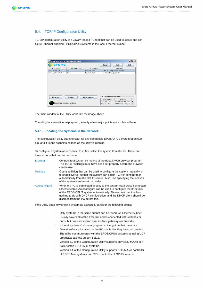
Efore OPUS Power System User Manual
60
5.4. TCP/IP Con guration Utility
TCP/IP con guration utility is a Java™-based PC tool that can be used to locate and con- gure Ethernet-enabled EPOS/OPUS systems in the local Ethernet subnet.
The main window of the utility looks like the image above.
The utility has an online help system, so only a few major points are explained here.
5.4.1. Locating the Systems in the Network
The con guration utility starts to scan for any compatible EPOS/OPUS system upon star-tup, and it keeps scanning as long as the utility is running.
To con gure a system or to connect to it, rst select the system from the list. There are three actions that can be performed:
Browser Connect to a system by means of the default Web browser program. The TCP/IP settings must have been set properly before the browser can be used.
Settings Opens a dialog that can be used to con gure the system manually, or to enable DHCP so that the system can obtain TCP/IP con guration automatically from the DCHP server. Also, text specifying the location of the system can be set manually.
Autocon gure When the PC is connected directly to the system via a cross-connected Ethernet cable, Autocon gure can be used to con gure the IP details of the EPOS/OPUS system automatically. Please note that this has nothing to do with DHCP con guration, and the DHCP client should be disabled from the PC before this.
If the utility does now show a system as expected, consider the following points:
• Only systems in the same subnet can be found. An Ethernet subnet usually covers all of the Ethernet nodes connected with switches or hubs, but does not extend over routers, gateways or rewalls.
• If the utility doesn’t show any systems, it might be that there is a rewall software installed on the PC that is blocking the scan queries. The utility communicates with the EPOS/OPUS systems by using UDP broadcast packets on port 51111.
• Version 1.0 of the Con guration Utility supports only ESC-MA.48 con-troller of the EPOS Mini systems.
• Version 1.1 of the Con guration Utility supports ESC-MA.48 controller of EPOS Mini systems and VIDI+ controller of OPUS systems.
Efore OPUS Power System User Manual
61
5.5. Web Interface
5.5.1. Introduction
The web interface can be accessed using any HTML 4.01 standards-conforming Web browser, such as:
• Mozilla Firefox, tested with versions 2 and 3• Mozilla SeaMonkey, tested with version 1.7• Microsoft Internet Explorer, tested with version 5 and 6
Both HTTP and HTTPS (HTTP over SSL) protocols are supported. The URLs for the VIDI+ Web interface are:
HTTP http://ip.address/HTTPS https://ip.address/
where ip.address is the numeric or literal IP address of the VIDI+. See Section 5.3 (Ether-net port) for more information on how to con gure and determine IP address of the VIDI+.
When connecting to the web interface of VIDI+ using HTTPS, your browser may complain about an untrusted certi cate. This happens because VIDI+ self-signs the SSL certi cates it uses for secure connections. It is safe to trust the certi cate, and it is recommended to allow the browser to remember the certi cate permanently.
5.5.2. Login
The web interface session must be started by logging in. The login screen asks for user name and password. See Section 5.7 (User Levels) for more information on user levels and passwords. It is also possible to select the language for the session from the login screen. The available depend on the version of the VIDI+ software.
Only one user can be logged in at a time, this includes usage of the local user interface. When there is a remote user logged in, the local user interface returns to the main display and indicates that a remote user has logged in. No actions are possible from the local user interface during a remote login session.
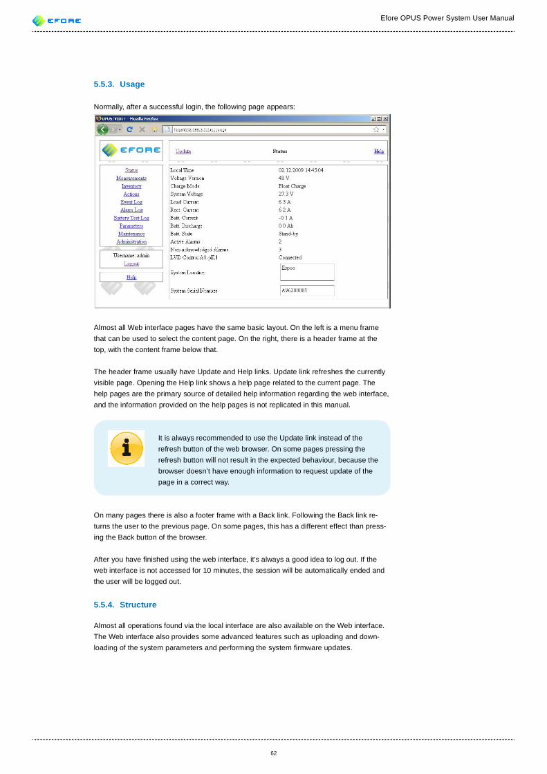
Efore OPUS Power System User Manual
62
5.5.3. Usage
Normally, after a successful login, the following page appears:
Almost all Web interface pages have the same basic layout. On the left is a menu frame that can be used to select the content page. On the right, there is a header frame at the top, with the content frame below that.
The header frame usually have Update and Help links. Update link refreshes the currently visible page. Opening the Help link shows a help page related to the current page. The help pages are the primary source of detailed help information regarding the web interface, and the information provided on the help pages is not replicated in this manual.
It is always recommended to use the Update link instead of the refresh button of the web browser. On some pages pressing the refresh button will not result in the expected behaviour, because the browser doesn’t have enough information to request update of the page in a correct way.
On many pages there is also a footer frame with a Back link. Following the Back link re-turns the user to the previous page. On some pages, this has a different effect than press-ing the Back button of the browser.
After you have nished using the web interface, it’s always a good idea to log out. If the web interface is not accessed for 10 minutes, the session will be automatically ended and the user will be logged out.
5.5.4. Structure
Almost all operations found via the local interface are also available on the Web interface. The Web interface also provides some advanced features such as uploading and down-loading of the system parameters and performing the system rmware updates.
Efore OPUS Power System User Manual
63
Below is a brief description of information that can be found on each Web interface page:
Status Shows status information for the system at a glance. Measurements Detailed information about various system measurements and alarm
inputs. Actions Option to start and stop battery test, boost charging and clear the bat-
tery Ah counter. Event Log A log of various system events. Alarm Log The alarm log. Battery Test Log A display of all completed and ongoing battery tests.System Logs Logs of battery discharge, battery temperature and system output
power.Inventory Module and device inventory for the system, shown in a tree-like struc-
ture. All device- and module-speci c con gurations and measurements are also accessible via the Inventory menu.
Parameters System parameters, including alarm matrix con guration. Maintenance Certain maintenance testing operations. Administration Various administrative actions, such as changing of the date and time,
management of passwords, system location text, loading of factory default parameters, and performing system rmware updates.
5.6. Terminal InterfaceThe terminal interface can be accessed with the Telnet and SSH protocols via an Ethernet port and by means of terminal software via RS-232.
5.6.1. Telnet
Telnet is an unencrypted terminal protocol for TCP/IP. Unencrypted means that all packets, including password data, are transmitted in clear-text form.
To connect to a VIDI+ via Telnet, start a telnet program and open a connection to the IP address of the VIDI+.
5.6.2. SSH
The SSH (Secure Shell) protocol is indented as a secure replacement for Telnet. All mes-sages are transmitted in encrypted form.
On the rst SSH connection from any given PC to a certain VIDI+ controller, the SSH program is likely to warn about unknown peer. This is normal, as each VIDI+ controller generates a new SSH server certi cate upon the rst start-up.
5.6.3. RS-232
See Section Section 5.2 (RS-232 Port) for more information on using the RS-232 port.
To start a terminal session, open a terminal program, select an appropriate serial port and make sure the serial settings are OK, then press Enter several (3-10) times until a Login: prompt appears.
If possible, use VT100 terminal emulation mode.
5.6.4. Login
A remote interface username and password is required for login. See Section 5.7 (User Levels) for more information on this matter.
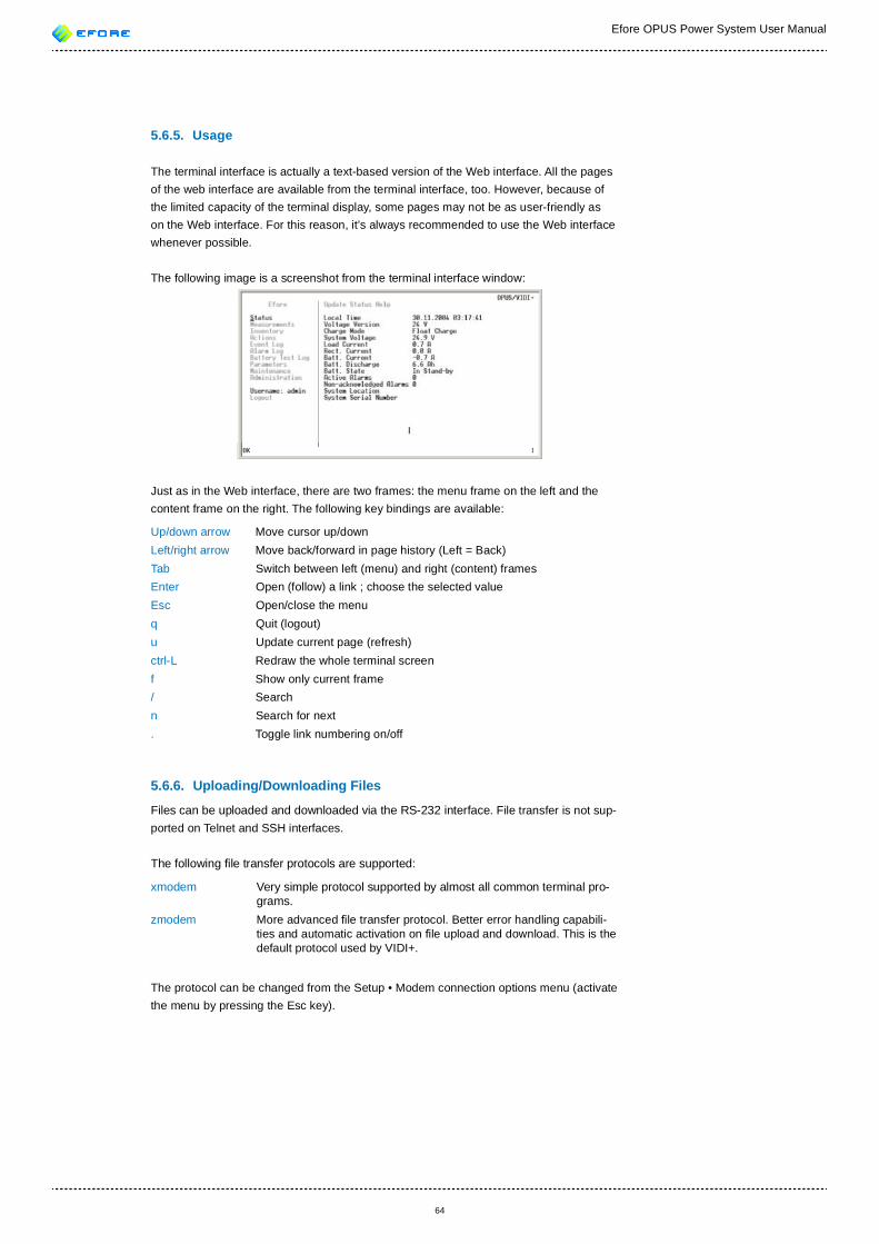
Efore OPUS Power System User Manual
64
5.6.5. Usage
The terminal interface is actually a text-based version of the Web interface. All the pages of the web interface are available from the terminal interface, too. However, because of the limited capacity of the terminal display, some pages may not be as user-friendly as on the Web interface. For this reason, it’s always recommended to use the Web interface whenever possible.
The following image is a screenshot from the terminal interface window:
Just as in the Web interface, there are two frames: the menu frame on the left and the content frame on the right. The following key bindings are available:
Up/down arrow Move cursor up/down Left/right arrow Move back/forward in page history (Left = Back)Tab Switch between left (menu) and right (content) framesEnter Open (follow) a link ; choose the selected valueEsc Open/close the menu q Quit (logout)u Update current page (refresh)ctrl-L Redraw the whole terminal screenf Show only current frame/ Searchn Search for next. Toggle link numbering on/off
5.6.6. Uploading/Downloading Files
Files can be uploaded and downloaded via the RS-232 interface. File transfer is not sup-ported on Telnet and SSH interfaces.
The following le transfer protocols are supported:
xmodem Very simple protocol supported by almost all common terminal pro-grams.
zmodem More advanced le transfer protocol. Better error handling capabili-ties and automatic activation on le upload and download. This is the default protocol used by VIDI+.
The protocol can be changed from the Setup • Modem connection options menu (activate the menu by pressing the Esc key).
Efore OPUS Power System User Manual
65
Example: downloading a parameters XML le1. Use the menu frame to open the Parameters page.2. Press Tab to switch to the right frame.3. Move the cursor to the link titled params.xml under the text
Download System Parameter File4. Press Enter.5. In some versions, a le name prompt appears. Just press Enter. 6. A dialog appears:
Download will start automatically...7. Press OK.8. Depending on your terminal program, the download may or may not
start automatically. If it does not, start the download manally. Refer to documentation of the terminal program if necessary.
9. A le called params.xml should be available on your computer. If the terminal program didn’t prompt for download location, look for the le in the current work directory (which may be C:\).
Example: uploading a parameters XML le
1. Use the menu frame to open the Parameters page.2. Press tab to switch to the right frame.3. Move the cursor over the text eld (empty underlined row) under the
text Upload System Parameter File.4. Press Enter.5. Write a parameter le name (e.g. params.xml).6. Press Enter.7. Move the cursor to the link titled [Upload]8. Press Enter9. A dialog prompting you to start the upload appears.10. Start the upload from your terminal program. Select from the menu
Transfer\Send File. Select the le to be uploaded and choose the used protocol. Press Send.
11. The VIDI+ checks the upload parameters, and prompts for accepting the changes. Note that uploading parameters may affect depending parameters, too.
5.6.7. Changing Parameters
To change the value of a parameter in the terminal interface, follow these steps:
1. Open the Parameters page in the menu frame.2. Press Tab to switch to the right frame.3. Navigate in the Parameters page until you nd the parameter to be
modi ed.4. Move the cursor to the Current value eld.5. Press Enter to start editing the value. You can use the left and right ar-
row keys to move the cursor to the text eld. Press the down arrow key when nished. Do not press Enter, as that cancels the changes.
6. Move the cursor over the [ Apply ] button and press Enter.
5.7. User Levels
There are three user levels available for remote interfaces of VIDI+:
User Read-only accessPower Access to basic maintenance actionsAdmin Full access
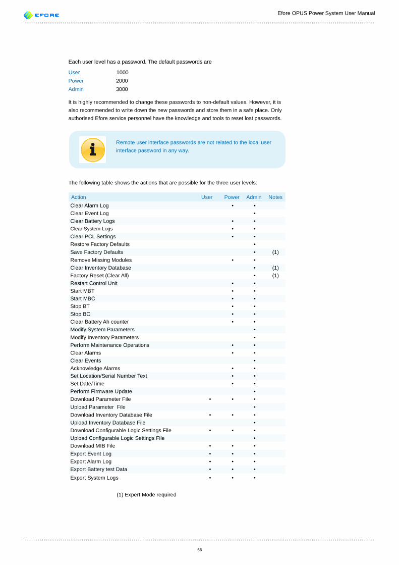
Efore OPUS Power System User Manual
66
Each user level has a password. The default passwords are
User 1000Power 2000Admin 3000
It is highly recommended to change these passwords to non-default values. However, it is also recommended to write down the new passwords and store them in a safe place. Only authorised Efore service personnel have the knowledge and tools to reset lost passwords.
Remote user interface passwords are not related to the local user interface password in any way.
The following table shows the actions that are possible for the three user levels:
Action User Power Admin NotesClear Alarm Log • •Clear Event Log •Clear Battery Logs • •Clear System Logs • •Clear PCL Settings • •Restore Factory Defaults •Save Factory Defaults • (1)Remove Missing Modules • •Clear Inventory Database • (1)Factory Reset (Clear All) • (1)Restart Control Unit • •Start MBT • •Start MBC • •Stop BT • •Stop BC • •Clear Battery Ah counter • •Modify System Parameters •Modify Inventory Parameters •Perform Maintenance Operations • •Clear Alarms • •Clear Events •Acknowledge Alarms • •Set Location/Serial Number Text • •Set Date/Time • •Perform Firmware Update •Download Parameter File • • •Upload Parameter File •Download Inventory Database File • • •Upload Inventory Database File •Download Con gurable Logic Settings File • • •Upload Con gurable Logic Settings File •Download MIB File • • •Export Event Log • • •Export Alarm Log • • •Export Battery test Data • • •Export System Logs • • •
(1) Expert Mode required
Efore OPUS Power System User Manual
67
5.8. SNMP/SMTP Alarm Noti cation
VIDI+ version 2.x and later support SNMP/SMTP alarm noti cations. SNMP traps or SMTP e-mails can be sent in response to speci ed events.
The main difference between SNMP and SMTP is that SNMP trap alarm noti cation is designed for automatic handling of alarms, while e-mail messages are targeted mainly at human receivers. Of course, how the traps or e-mail messages are ultimately used, is fully up to the end user.
5.8.1. SNMP
SNMP (Simple Network Management Protocol) version 2c traps are supported. SNMP traps are UDP datagrams (packets) that are sent to an appropriately con gured NMS (net-work management station).
An SNMP MIB le called EFORE-MIB.TXT or EFORE.MIB , provided by Efore, can be used with the NMS software for proper decoding of SNMP traps sent by the VIDI+.
Two kinds of traps are supported:
Alarm trap When alarm traps are enabled, one alarm trap is sent per alarm event. Sending can be con gured to occur on alarm state changes (activation, acknowledgement, or deactivation) or at speci ed intervals when an alarm is in a certain state or certain states. Alarm traps contain informa-tion on the alarm code, alarm message, activation time, duration, and alarm relays .
Overview trap An overview trap includes the total numbers of active and non-acknowl-edged alarms in the system. Also the current status of system alarm relays is included.
Both alarm and overview traps can be enabled or disabled individually. The system alarm relay information can be used to determine alarm criticality level. However, it is fully up to the end user to specify which alarm relays signal which criticality level, or to ignore such a classi cation.
SNMP con guration can be performed from Parameters • Communication Parameters • SNMP.
It is possible to specify multiple NMS IP addresses by separating the addresses with com-mas. Example:
nms1.efore. , nms2.efore.
5.8.2. SMTP
When SMTP (Simple Mail Transfer Protocol) alarm e-mail noti cation is enabled, informa-tion about the selected alarms is sent in an email message to the speci ed recipients. Sending can be con gured to occur at speci ed intervals or only when a particular alarm changes state.
SMTP con guration can be found from Parameters • Communication Parameters • SNMP.
Multiple e-mail recipients can be speci ed through separation of the addresses with com-mas
Efore OPUS Power System User Manual
68
5.9. Administration
5.9.1. Changing the Date/Time
Date/Time con guration can be found on the Administration • Date/Time page.
On this page, both local and UTC (Universal Time Coordinated, also known as Greenwich Mean Time, GMT) time is shown. The difference between the local and UTC times is deter-mined by the time zone, which can be set from the same page.
If the local or UTC time is wrong, rst check that the time zone is correctly set, and then adjust the local time to the correct value.
The VIDI+ has NTP (Network Time Protocol) client support. It is recommended to use NTP to maintain the correct date and time whenever possible. Using NTP requires that an NTP server be available in the network. Efore recommends that end users use an NTP server supported by the local site network.
The Date/Time page provides a list of public NTP servers. The list of prede ned servers is sourced from support.ntp.org, and the regulations and rules speci ed there apply. All NTP servers listed are provided and maintained by third parties and Efore is in no way related to those parties. Usage of the prede ned servers is fully at the end user’s responsibility. Efore does not provide any support for addressing problems related to use of any servers or services not maintained by Efore.
5.9.2. Programmable Con guration Logic
The programmable con guration logic settings can be accessed from the menu Administra-tion • Con gurable Logic. Only the admin user can change these settings.
On the Con gurable Logic page you can de ne different kind of events to start differ-ent kind of actions in the OPUS system. The con guration logic is based on connections between events and actions.
Events of the con guration logic are:• Control Inputs: these inputs are alarm input devices of the OPUS
system that are con gured as an ‘External Control’. Only the External Control devices can be seen in the Control Input list. If there is none External Control input in the VIDI+ then the Control Inputs list is empty.
• Alarms: Any alarm of the VIDI+ controller. If an alarm is disabled in the Parameters • Alarm Parameters it can’t be used either via the PCL.
• System States: Indication whether a boost charging or a battery test state is active.
Actions of the con guration logic are:• System Controls: Control of boost charging and battery tests.• Control Relays: these devices are alarm relays that are con gured as
Control relays.
System states that can cause some action are:• Boost Charging Active• Battery Test Active
Efore OPUS Power System User Manual
69
System controls that can result from any events are:• Disable Boost Charging• Start Boost Charging• Disable Battery Tests• Start Battery Test
An event can be connected to any number of entries in the System Control and Control Re-lays lists. More than one event can be connected to a same action in the System Controls or Control Relays. For all the events, at least one action must be chosen for it to be in use. To select or unselect an entry in a list press the Ctrl button while clicking on the entry.
To submit changes press the Submit button. To discard changes and return to the previous con guration, press the Restore Previous button.
Following parameters can be con gured for each event.
• When Alarm Active: (Alarms only) If selected, the event will be active when the alarm is active. If neither this nor ‘When Alarm Not Ack-d’ is selected, event will be set inactive.
• When Alarm Not Ack-d: (Alarms only) If selected, the event will be active when the alarm has not been acknowledged. If neither this nor ‘When Alarm Not Active’ is selected, event will be set inactive.
• Disabled: (Other than alarms only) If selected, the event will be set inactive.
• Inverted: If selected, the state of an event will be inverted.• Activation Delay: On transition from inactive to active state of the
event, the speci ed delay will be applied before the action changes to active state.
• Deactivation Delay: On transition from active to inactive state of the event, the speci ed delay will be applied before the action changes to inactive state.
It should be noted that while the Con gurable Logic provides functionality similar to input/output selection of alarm parameters and Alarm Matrix, these con gurations are mostly independent of each other.
Doing changes to the Con gurable Logic doesn’t affect alarm parameters in any way. Because the Con gurable Logic operates with Control Relays and External Control inputs, selection of external alarm inputs or alarm relays in alarm parameters does not affect the Con gurable Logic.
However, all other alarm parameters (Enabled/Disabled, Delay, thresholds) control activa-tion of alarms and thus have effect on Alarm-based inputs of the Con gurable Logic, too.
To see an overview of connections and the current states of inputs and outputs, click the Connection Overview Matrix link.
The con guration logic settings can be downloaded and uploaded in XML format. To down-load the PCL le from the system press the link ‘pcl.xml’ on the Con guration logic page. Save the le or open it with a programm suited for the purpose. Only the admin user can upload a PCL le to the system. To do this press the Browse button and select a PCL le.Then press the Upload button.
5.9.3. Administrative Actions
The Administrative actions page can be found from the Administration menu. Most actions are allowed only for the admin-level user, but some can be performed by the power-level user, too. See Section 5.7 (User Levels) for details on this.
Administrative actions cannot be undone. Think before acting.
Some actions are hidden until the Expert Mode parameter is Enabled from System Param-eters.
Clear Alarm Log Clears all alarms from the alarm log, except the currently active alarms.Clear Event Log Clears all events from the event log. A new event indicating that the
event log was cleared, will be generated after clearing. Clear Battery Logs Clears all battery test log entries.Clear Battery Discharge Log Clears the battery discharge log entries.Clear Battery Temperature Log Clears the battery temperature log entries.Clear System Power Log Clears the system power log entries.Clear Programmable Logic Con guration Clears the programmable logic con guration settings.Restore Factory Default Parameters Replaces the current system parameters with factory parameters.
Initially the factory parameters have been saved to the controller at the factory after the initial con guration, but it is possible to overwrite those parameters later (see Save Parameters As Factory Defaults).
Save Parameters as Factory Defaults (Expert Mode required) Save the current parameters as the factory parameters, so that they
can be restored later via the Restore Factory Default Parameters ac-tion.
Remove Missing Modules Removes all modules and related devices from the inventory database
that are no longer present in the system. This may be useful to free space in the inventory database, or to get rid of references to removed modules in certain parts of the user interfaces.
Clear Inventory Database (Expert Mode only) Clear all modules and devices from the inventory database. All device
and module con gurations will be lost. The controller software will be restarted.
Factory Reset (Expert Mode only) Clears all con gurations and logs from the system, including those
for all connected PowerCAN modules. As the name “Factory Reset” suggests, the controller modules will be like fresh units from the factory (without pre-con guration done) after this action. The controller soft-ware will be restarted.

This feature is mainly intended for use only in testing and for the manu-facturer’s service purposes.
Reboot System Control Unit Reboots the VIDI+ Advanced Controller, including the operating sys-
tem. This operation takes about a minute, during which the LUIF may indicate that the system master control unit is not responding.
This may be necessary after the rmware of the VIDI+ Advanced Con-troller has been updated.
Restart System Control Unit Software (Expert Mode only) Restart the VIDI+ control software. This operation takes a few seconds.
5.10. Downloading and Uploading System Inventory DatabaseIt is possible to download and upload inventory database in XML format from the main Inventory page. This may be useful for backup purposes and cloning of identical or nearly identical systems.
After inventory database XML le has been uploaded, it is possible to select which modules will be affected by the new con gurations. On the Inventory Database Import page you can map con gurations read from the uploaded XML le to system modules.
Each module con guration found from the uploaded XML le will be shown on the left side of the page. For each such module con guration, a list of possible target modules present in the system is shown on the right side.
Only con gurations of modules of an equal type can be mapped. It is possible to omit map-ping of a con guration by selecting the “Drop from the list” option from the target list.
To see physical location of a target module, select a module from a target list and press the corresponding Blink button. If the selected module supports this, it will blink its status LED in yellow color for a few times.
To update list of available target modules, press Refresh button.
When nished, press Submit button. After this, it is recommended to inspect the con gura-tions of the affected modules from the Inventory tree.
5.11. Downloading and Uploading System ParametersSystem parameters can be downloaded and uploaded from the main Parameters page of the Web interface. The parameter le is in XML format.
When uploading the parameters, the controller checks which parameters have changed and checks that the new values are valid. If changes affect any dependent parameter, the values are updated if necessary. All dependent parameters are presented to the user.
In some versions of VIDI+ the values determined by internal param-eter dependencies override values speci ed in the uploaded le. This may cause that values of the depending parameters are not updated correctly. This problem can be worked around by upload-ing the parameters again.
Although possible, it is not recommended to modify the parameter XML les by hand, as this is prone to errors and may cause dependency problems. Efore does not provide sup-port for solving problems caused by manual parameter le changes.
5.12. System Logs and Data ExportingThe VIDI+ controller collects data from the system. The data is stored to different logs and it can be exported in XML and CSV format with or without headers. To export the data select a wanted le format on the Log page and press the Export button. The data of the system is collected to the following logs
Alarm Log The alarm log displays contents of the system alarm log. A user can
select to wiew all, active or unacknowledged alarms. The default view is all alarms. On the exported log is the same data as on the alarm log page at the time.
Event Log The event log shows all events of the system. On the exported log is
the same data as on the event log page. Battery Test Log Each battery test data is stored to the log. On the battery test log page
is shown a list of all done battery tests. To see a data of an individual battery test press a link Download in the end of the row. On the battery test data page is shown the battery test con guration parameters and measured data. The exported data contains all measurements.
Battery Discharge Log The battery discharge log displays statistics about a depth of a battery
discharge during mains faults or battery tests. A depth of a discharge, is calculated as a ratio of discharged ampere hours to the battery nominal capasity. The depth of discharge is determined at an end of a mains fault or battery test and the statistic is updated. An exported data contains a data of this table.
Battery Temperature Log The battery temperature log displays statistics about battery tempera-
ture. The VIDI+ controller calculates the total cumulative time that battery temperature resides in each temperature range. The values are updated once per hour. If there are multible battery temperature sen-sors available, the highest measured value will be used. If there is no battery temperature sensor, the values will not be updated. An exported data contains a data of this table. The time column’s value is a decimal number and the unit is hour (e.g. the table’s value 162 h 59 m can be shown as 162,9931 hours).
System Power Log The system power log shows graphical presentation of total system
output power as a function of time. The log data is measured once per second, but the curve data is updated only once per hour. If the unit selected for the X-axis is a day, the maximum time scale is one year. If the unit is an hour, the maximum scale is one month (31 days). The power curve can be seen with different resolutions (small, medium and large). To the exported data the time scale and resolution don’t effect.
5.13. Firmware UpdateThe following OPUS components support rmware update:
• VIDI+ system controller module• UIF module• MRC recti ers• LVD module• BM module • SAM module
The rmware updates are controlled by the VIDI+ controller.
Efore takes no responsibility whatsoever of any damage caused by failed rmware updates, or damages caused by limited system functionality during the rmware update.
5.13.1. Update Methods
Two update methods are available:
Repository update The VIDI+ connects to the given HTTP repository (usually maintained
by Efore), determines which updates are available, and downloads the required update packages.
Package update A rmware update package is uploaded to the VIDI+. The package may
contain update images for single or multiple system module type.
The choice of the update method depends on the circumstances. If you want to perform a generic system rmware update, the repository update is the easiest way. However, that requires that the VIDI+ system is able to access the HTTP repository. In some site network con gurations, this may not be possible. The package update method can be used in all cases. When updating multiple module types, the package update method also grants bet-ter control over the update sequence, provided that you have a separate update package for each module type.
On the rmware update page, there is also an option for allowing downgrading of rmware versions. This should be used only if a newer rmware version has been diagnosed to be incompatible with your system, or if you want to reapply the same rmware version. Re-updating may be useful if you simply want to test the rmware update process.
5.13.2. Performing Firmware Update
The rmware update can be initiated from the Web interface by opening the Administration • Firmware Update page.
Repository Method
Enter a valid update repository URL (for the repository method) . If downgrading or same-grading is to be allowed, tick the related Allow downgrading box. Press the Download button.
The controller will connect to the update repository, determine which updates are , and check that all required les exist. This may take some time, especially if the connection to the update server is slow.
Update Package Method
On the rmware update page, select a rmware update package for the Update Package eld. If downgrading or same-grading is to be allowed, tick the related Allow downgrading box. Press the Upload button. The upload may take a while, especially if the update pack-age is large or connection to the VIDI+ is slow.
Starting the Update
After the controller has selected the viable rmware updates, the user interface will show which modules will be updated and which versions will be used. The user will need to con rm the start of the update.
After con rmation, the update starts. The user interface will indicate the status and progress of the update for each module present in the system.
Finishing the Update
For all modules the rmware update will be nished automatically and no user actions are required. If the advanced controller board of the VIDI+ controller is being updated, it will reboot itself after the update.
After the rmware update is nished, it is recommended to check the versions and status information for the updated modules from the Inventory menu. It’s also a good idea to check that there are no unexpected alarms in the alarm log
5.13.3. Module-Speci c Update Notes
The VIDI+
The VIDI+ features two separate controller boards inside the VIDI+ controller module: the standard controller and the advanced controller. The advanced controller provides all of the remote interfaces functionality, and it controls the rmware update process.
The VIDI+ Advanced Controller
• Should be updated last.• Most system control functions will be operational during the update, but
some system functionality may be degraded, disabled or unavailable.• Controller reboot is required after the update. • During the reboot, the local display may indicate that the main system
controller is not responding. This is normal unless the normal operation does not recover in a few minutes.
VIDI+ Standard Controller
• The standard controller is visible as a PowerCAN module for the advanced controller.
• While the standard controller is being updated, there may be breaks in communication with other system modules, as all PowerCAN traf c is routed via the standard controller.
• All the alarm relays will be active during the update.• If a non-latching LVD contactor is being used, the contactor will be
disconnected during the update.
UIF (Local Display Module)
• The display and the controls are nonfunctional during the update.
MRC Recti ers
• The recti er will not supply power while being updated.• If there are two or more unloaded recti ers in the system, the controller
will update two of them at a time, otherwise only one recti er.
• If updating fails for a single MRC module even after multiple retries, the update will be aborted. Otherwise, there would be a risk of the system being left without any functional recti ers.
LVD Module
• The module will be nonfunctional during the update. • If a non-latching LVD contactor is being used, the contactor will be
disconnected during the update.
BM Module
• The BM module will be nonfunctional during the update.
SAM Module
• The SAM module will be nonfunctional during the update.
5.13.4. Firmware Redundancy
All PowerCAN-connected modules have two sets of rmware:
Main The main application rmware.CANLoader More compact rmware that is used only for updating the main
rmware.
If an update of the main rmware of a PowerCAN-connected module fails during the update for any reason, the main rmware will be nonfunctional as the result. However, it will still be possible to retry the update, because the CANloader rmware is still functional.
The main rmware can update CANloader rmware. If the update of CANloader fails, the module functionality is not degraded except that the main rmware update is not possible. Broken CANloader rmware can be xed by restarting the rmware update.
The VIDI+ Advanced Controller itself also has two sets of rmware, but the update mecha-nism is slightly different. The ash memory of the VIDI+ has been divided into two identical areas, each holding a version of the main rmware. On controller start-up, the newer of these two sets of rmware is started, unless it has been marked as nonfunctional. Should a rmware update fail, there is no danger to system functionality, because the failed rmware will not be started. If the update is successful but the new rmware is nonfunctional, the old rmware will be re-selected after an unsuccessful run.
Efore OPUS Power System User Manual
76
6. SYSTEM MAINTENANCE
6.1. General
All control modules and recti ers can be removed from and installed in the system while the system is operational.
It is usually possible to install and remove fuses in a live system, but because of the high risk of electric shock (due to high voltage and/or current) involved, this may only be done by a properly trained professional.
6.2. Removing Recti er/Inverter/Bypass ModuleRefer to the Installation and Start-up Manual of the system for instructions on unplugging a recti er/inverter/bypass module from the system.
To remove the old recti er/inverter/bypass module from the inventory database of the VIDI+ controller, refer to Section 4.10.6 (Removing Obsolete Modules from Inventory).
6.3. Adding a New Recti er/Inverter/Bypass ModuleRefer to the Installation and Start-up Manual of the system for instructions on plugging in a recti er/inverter/bypass module for the system.
After the recti er/inverter/bypass module is connected and powered up properly, a dialog reporting an uncon gured module should appear on the local user interface. Enter the cor-rect settings for the new recti er. Refer to Subsection Section 4.2.3 (Uncon gured Modules Dialog) for information .
6.4. Replacing the System Controller ModuleTo remove the system controller module, follow these steps:
1. Disconnect the cable set from the power connector (marked ‘PWR’)2. Disconnect all other cables3. Remove the xing screws4. Remove the module from the system
Install the new module:
1. Install the module in the correct place2. Attach the screws3. Connect all cables except the power connector cable set4. Connect the power connector cable set5. The controller should power up6. Con gure the new controller module
Efore OPUS Power System User Manual
77
If the new controller module had been used in an other system before, it is highly recom-mended to perform a factory reset for the new module:
1. Disconnect all PowerCAN bus cables (marked ‘CAN1’, ‘CAN2’) except UIF (marked ‘CAN2/UIF’) from the VIDI+ controller module
2. If the system isn’t powered up yet, power it up now and wait until the controller is ready
3. If you wish to use the Web interface, log in to the system as the admin user
4. Enable Expert Mode from the System Parameters menu 5. From the local interface, select Actions • Clear All Data. Alternatively,
from the Web interface, select Admin • Administrative Actions • Factory Reset.
6. Con rm the operation
Factory Reset will erase all con guration data and data logs in the controller, including fac-tory parameters (the parameter settings loaded initially at the factory). If you don’t want to lose the factory parameters, you can use a combination of the following functions:
• Clear Inventory to erase all module and device con gurations• Restore Factory Parameters to load the system parameters set at the
factory • To clear the old log data: Clear Alarm Log, Clear Event Log, Clear
Battery Logs, Clear Battery Discharge Log, Clear Battery Tempera-ture Log, Clear System Power Log and Clear Programmable Logic Con guration
Connect the PowerCAN cables to the VIDI+ controller. The controller gets the module and device settings from the modules installed in the system.
Refer to Section 4.2 (The First Start-up) for more information on initial con guration of the controller module.
6.5. Adding or Removing Other System ModulesFollow module-speci c instructions. Where they do not specify otherwise, follow these common steps to remove a module:
1. Disconnect the power cable set connector (marked ‘POWER’)2. Disconnect all other cables3. Remove the module from the system4. Remove the old module from the controller’s inventory, as described in
Section 4.10.6 (Removing Obsolete Modules from Inventory); if a mod-ule is to be replaced, this step can be performed after the new module has been installed.
The common steps to install a new module:
1. Install the new module into the system2. Connect all cables except the power connector3. Connect the power connector cable set4. Con gure the new module
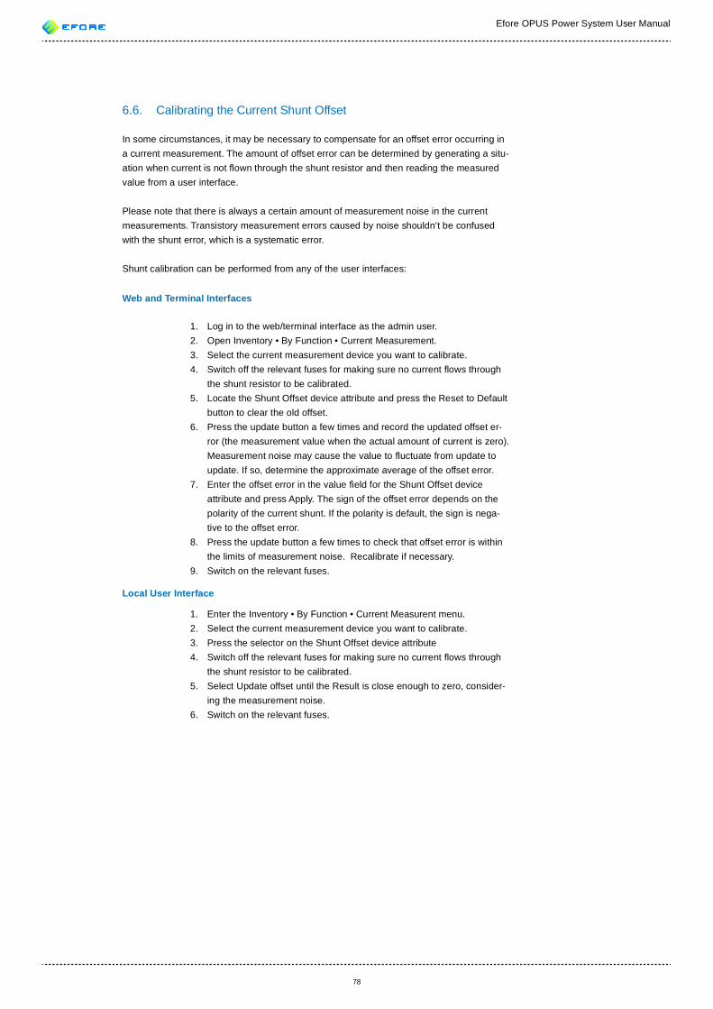
Efore OPUS Power System User Manual
78
6.6. Calibrating the Current Shunt Offset
In some circumstances, it may be necessary to compensate for an offset error occurring in a current measurement. The amount of offset error can be determined by generating a situ-ation when current is not own through the shunt resistor and then reading the measured value from a user interface.
Please note that there is always a certain amount of measurement noise in the current measurements. Transistory measurement errors caused by noise shouldn’t be confused with the shunt error, which is a systematic error.
Shunt calibration can be performed from any of the user interfaces:
Web and Terminal Interfaces
1. Log in to the web/terminal interface as the admin user.2. Open Inventory • By Function • Current Measurement.3. Select the current measurement device you want to calibrate.4. Switch off the relevant fuses for making sure no current ows through
the shunt resistor to be calibrated.5. Locate the Shunt Offset device attribute and press the Reset to Default
button to clear the old offset.6. Press the update button a few times and record the updated offset er-
ror (the measurement value when the actual amount of current is zero). Measurement noise may cause the value to uctuate from update to update. If so, determine the approximate average of the offset error.
7. Enter the offset error in the value eld for the Shunt Offset device attribute and press Apply. The sign of the offset error depends on the polarity of the current shunt. If the polarity is default, the sign is nega-tive to the offset error.
8. Press the update button a few times to check that offset error is within the limits of measurement noise. Recalibrate if necessary.
9. Switch on the relevant fuses.
Local User Interface
1. Enter the Inventory • By Function • Current Measurent menu.2. Select the current measurement device you want to calibrate.3. Press the selector on the Shunt Offset device attribute4. Switch off the relevant fuses for making sure no current ows through
the shunt resistor to be calibrated.5. Select Update offset until the Result is close enough to zero, consider-
ing the measurement noise. 6. Switch on the relevant fuses.
Efore OPUS Power System User Manual
79
7. PARAMETERS
7.1. Parameter and Alarm Parameter Groups
Diagrams in the appendices B and C illustrate the hierarchy of the parameters and alarm parameters - i.e., how they are grouped in the user interfaces and con guration les. The individual alarm param-eters (Enabled/Disabled, Delay, and Relay List) have been omitted from the diagram for the sake of readability
7.2. Parameter DescriptionsThe rest of this chapter contains parameter descriptions for the VIDI+ controller. Names of parameters are used in the user interfaces and are referred to in many places in this document.
Parameters can have dependencies as described in Section 3.1 (Parameter System) In some cases, a system parameter affects values of device attributes.
When a depending parameter goes out of a range because a higher-level parameter has been changed, the depending parameter will be set to a default value instead of minimum/maximum value, unless the default value is not valid. If the default value is not valid, the minimum/maximum limit is used.
Efore OPUS Power System User Manual
80
7.2.1. System Parameters
Expert Mode Expert Mode allows access to some base parameters which don’t directly affect system operation but affect other parameters.
Cells Per Block Number of battery cells per battery block. In a normal 12 V lead-acid battery block there are 6 cells per block. If block is the same as cell, use value of 1.
Voltage Version De nes voltage version of the system as number of battery blocks per string. For 12 V battery blocks, value 4 of this parameter means a 48 V system.
Recti er Voltage Group De nes voltage group of recti ers to be controlled. This value must match with the voltage group of the installed recti ers. Recti er voltage groups are: 2 for 24V, 4 for 48V etc. When ca. 12 V battery blocks are used, value of this parameter is equal to Voltage Version.
System Nominal Current Nominal maximum current rating of the system. Also used as default value for current shunt nominal current settings.
Battery Capacity Total capacity of batteries in Ampere-hours.
Energy Save Mode Enable/disable energy save mode. When enabled, a minimum number of recti ers is used to supply power. The unused recti ers are put into a standby mode. This increases overall system ef ciency.
Language Language selection for the local interface.
Device names When enabled, user speci ed device names are shown in local display. If name hasn’t been given, device’s default name is used. When disabled, default names are used in the local display.
System Password Local Interface system password. If the password is 0000, it will not be asked.
7.2.2. Battery Parameters
Minimum Cell Voltage De nes minimum charge voltage per cell for all parameters.
Maximum Cell Voltage De nes maximum charge voltage per cell for all parameters.
Minimum Cell Monitoring Voltage De nes minimum monitoring voltage per cell for all parameters.
Nominal Cell Voltage De nes nominal cell voltage.
Float Charge Voltage per Cell De nes oat charge voltage per battery cell.
Boost Charge Voltage per Cell De nes boost charge voltage per battery cell.
TC Volts per Celcius per Cell Temperature compensation coef cient, volts per degree of celcius per cell.
7.2.3. Communication Parameters
DHCP Enabled Whether to enable DHCP support. DHCP can be used to obtain IP settings automatically from a network supporting DHCP. Note! Changing the setting will take effect after the logout.
IP Address IP Address for TCP/IP in format aaa.bbb.ccc.ddd. Note! Changing the IP address will take effect after the logout.
IP Netmask IP Netmask for TCP/IP in format aaa.bbb.ccc.ddd. Note! Changing the netmask will take effect after the logout.
IP Gateway IP address of gateway (router) for TCP/IP in format aaa.bbb.ccc.ddd. Note! Changing the gateway will take effect after the logout.
DNS Server 1 IP address of primary DNS server in format aaa.bbb.ccc.ddd.
DNS Server 2 IP address of secondary DNS server in format aaa.bbb.ccc.ddd.
RS-232 Baud rate Baud rate for serial port communications.
RS-232 Data Bits Number of data bits for serial port communications.
RS-232 Parity Parity checking mode for serial port communications.
RS-232 Stop Bits Number of stop bits for serial port communications.
7.2.3.1. SMTP Settings
SMTP Server IP address (numeric or FQDN) of SMTP mail relay server. Single entry only.
Trigger De nes the alarm states which cause sending of an alarm email.
Period Period for sending alarm mails in hours/minutes.
From The email address which is used as the sender of alarm emails.
To Email address of alarm mail recipient.

Efore OPUS Power System User Manual
81
7.2.3.2. SNMP Settings
SNMP Parameters IP address (numeric or FQDN) of SNMP NMS (Network Management Station). Multiple entries must be separated with a comma.
Trigger Alarm states which cause sending of per-alarm SNMP traps.
Period Period for sending alarm SNMP traps in minutes/seconds.
Send Overview Enables or disables sending of alarm overview SNMP traps.
7.2.3.3. EchoAgent Settings
Enabled/Disabled Enable/Disable EchoVault agent.
7.2.4. Charge Parameters
Float Charge Voltage Recti er voltage during oat charge. Float charge is the default charge state.
7.2.4.1. Charge Current Control
Enable/Disable De nes whether Battery Charge Current Control is enabled.
Charge Current Limit Limit for total battery charge current. Recti er output voltage is controlled to keep charge current below this limit. Battery current measurement devices have their invidual charge limits.
Fast Control Gain Control gain value for Charge Current Limit operating in fast mode. Smaller value makes charge current control more stable, bigger value makes it faster.
Slow Control Gain Control gain value for Charge Current Limit operating in slow mode. Smaller value makes charge current control more stable, bigger value makes it faster.
7.2.4.2. Boost Charge
Boost Charge Voltage Recti er output voltage during Boost Charging.
BC Minimum Temperature Minimum ambient temperature for Boost Charge operation.
BC Maximum Temperature Maximum ambient temperature for Boost Charge operation.
7.2.4.2.1. Manual Boost Charge
MBC Maximum Time Maximum Manual Boost Charge time.
7.2.4.2.2. Periodic Boost Charge
Enable/Disable De nes whether Periodic Boost Charge is enabled.
PBC Maximum Time Maximum Periodic Boost Charge time.
PBC Times in a Year Number of times Periodic Boost Charge is performed in a year.
7.2.4.2.3. Automatic Boost Charge
Enable/Disable De nes whether Automatic Boost Charge is enabled.
ABC Maximum Time Maximum Automatic Boost Charge time.
ABC Start Current Automatic Boost Charging is activated if battery charge current exceeds Start Current after a mains fault.
ABC Stop Current Automatic Boost Charging is deactivated if battery charge current drops below Stop Current.
7.2.4.2.4. Remote Boost Charge
Enable/Disable De nes whether Remote Boost Charge is enabled.
RBC Maximum Time Maximum Remote Boost Charge time.
Latching Input When Enabled, RBC will remain active after start until time limit is reached, regardless of the state of the control signal. When Disabled, RBC will be stopped also when control signal deactivates.
7.2.4.3. Temperature Compensation
Enable/Disable De nes whether Temperature Compensation is enabled.
TC Volts per Celsius Temperature to voltage ratio of Temperature Compensation.
TC Maximum Voltage Maximum charge voltage when using Temperature Compensation.
TC Minimum Voltage Minimum charge voltage when using Temperature Compensation.
TC Nominal Temperature The temperature at which Temperature Compensation does not have effect on the charge voltage.
7.2.5. Battery Tests
BT Ignore Time Settling time in the beginning of the test during which Stop Voltage is ignored.
Efore OPUS Power System User Manual
82
BT Shutdown Voltage Battery Test is always stopped when battery voltage drops below Shutdown Voltage
BT Min Precharge Time Minimum charge time before Battery Test can be started after a mains fault.
7.2.5.1. Manual Battery Test
MBT Stop Voltage Manual Battery Test is stopped when battery voltage drops below Stop Voltage and Ignore Time has passed.
MBT Time Limit Manual Battery Test testing time in hours / minutes. The test ends successfully when the time limit is reached. The BT Ignore Time speci es the minimum value for this parameter.
MBT Discharge Limit Maximum battery discarge limit for Manual Battery Test in Ampere hours. The test ends successfully when the discharge limit is reached. Set to zero to disable the limit.
7.2.5.2. Periodic Battery Test
Enable/Disable De nes whether Periodic Battery Test is enabled.
PBT Times in a Year Number of times Periodic Battery Test is performed in a year.
PBT Stop Voltage Periodic Battery Test is stopped when battery voltage drops below Stop Voltage and Ignore Time has passed.
PBT Time Limit Periodic Battery Test testing time in hours / minutes. The test ends successfully when the time limit is reached. The BT Ignore Time speci es the minimum value for this parameter.
PBT Discharge Limit Maximum battery discarge limit for Periodic Battery Test in Ampere hours. The test ends successfully when the discharge limit is reached. Set to zero to disable the limit.
7.2.5.2.1. Safe hours
PBT Monday Time Window PBT can be started on Monday in this time window (starthour:startminutes - stophour:stopminutes).
PBT Tuesday Time Window PBT can be started on Tuesday in this time window (starthour:startminutes - stophour:stopminutes).
PBT Wednesday Time Window PBT can be started on Wednesday in this time window (starthour:startminutes - stophour:stopminutes).
PBT Thursday Time Window PBT can be started on Thursday in this time window (starthour:startminutes - stophour:stopminutes).
PBT Friday Time Window PBT can be started on Friday in this time window (starthour:startminutes - stophour:stopminutes).
PBT Saturday Time Window PBT can be started on Saturday in this time window (starthour:startminutes - stophour:stopminutes).
PBT Sunday Time Window PBT can be started on Sunday in this time window (starthour:startminutes - stophour:stopminutes).
7.2.5.2.2. Forbidden days
PBT Forbidden Day 1 PBT is not allowed to start in this day of the year (month.day).
PBT Forbidden Day 2 PBT is not allowed to start in this day of the year (month.day).
PBT Forbidden Day 3 PBT is not allowed to start in this day of the year (month.day).
PBT Forbidden Day 4 PBT is not allowed to start in this day of the year (month.day).
PBT Forbidden Day 5 PBT is not allowed to start in this day of the year (month.day).
PBT Forbidden Day 6 PBT is not allowed to start in this day of the year (month.day).
PBT Forbidden Day 7 PBT is not allowed to start in this day of the year (month.day).
PBT Forbidden Day 8 PBT is not allowed to start in this day of the year (month.day).
PBT Forbidden Day 9 PBT is not allowed to start in this day of the year (month.day).
PBT Forbidden Day 10 PBT is not allowed to start in this day of the year (month.day).
7.2.5.3. Natural Battery Test
Enable/Disable De nes whether Natural Battery Test is enabled.
NBT Stop Voltage Natural Battery Test is stopped when battery voltage drops below Stop Voltage and Ignore Time has passed.
NBT Time Limit Natural Battery Test testing time in hours / minutes. The test ends successfully when the time limit is reached. The BT Ignore Time speci es the minimum value for this parameter.

Efore OPUS Power System User Manual
83
NBT Discharge Limit Maximum battery discarge limit for Natural Battery Test in Ampere hours. The test ends successfully when the discharge limit is reached. Set to zero to disable the limit.
7.2.5.4. Remote Battery Test
Enable/Disable De nes whether Remote Battery Test is enabled.
Latching Input When Enabled, RBT will remain active after start until time, discharge or voltage limit is reached, regardless of the state of the control signal. When Disabled, RBT will be stopped also when control signal deactivates.
RBT Stop Voltage Remote Battery Test is stopped when battery voltage drops below Stop Voltage and Ignore Time has passed.
RBT Time Limit Remote Battery Test testing time in hours / minutes. The test ends successfully when the time limit is reached. The BT Ignore Time speci es the minimum value for this parameter.
RBT Discharge Limit Maximum battery discarge limit for Remote Battery Test in Ampere hours. The test ends successfully when the discharge limit is reached. Set to zero to disable the limit.
7.2.6. LVD Defaults
7.2.6.1. Load LVD Defaults
Ld LVD Control Mode LVD Control mode de nes the basis for connecting and disconnecting the LVD contactor. Voltage: system voltage. Time: mains fault duration. Discharge: battery discharge during mains fault.
Ld LVD Contactor Type This must be set according to the type of the LVD contactor used.
Ld LVD Disconnect V LVD contactor is disconnected when system voltage drops below this threshold.
Ld LVD Pickup V LVD contactor is connected when system voltage rises above this threshold.
7.2.6.2. Battery LVD Defaults
Bt LVD Control Mode LVD Control mode de nes the basis for connecting and disconnecting the LVD contactor. Voltage: system voltage. Time: mains fault duration. Discharge: battery discharge during mains fault.
Bt LVD Contactor Type This must be set according to the type of the LVD contactor used.
Bt LVD Disconnect V LVD contactor is disconnected when system voltage drops below this threshold.
Bt LVD Pickup V LVD contactor is connected when system voltage rises above this threshold.
7.2.7. Inverter Parameters
Default Mode De nes the default AC source of the bypass switch.
Bypass Mains Min Voltage Minimum mains AC voltage which bypass switch accepts before switching to inverter supply.
Bypass Mains Max Voltage Maximum mains AC voltage which bypass switch accepts before switching to inverter supply.
Inverters Disconnect V Inverters DC supply low voltage disconnect voltage. If system DC voltage drops below this limit, the inverters will be shut down to save batteries.
Inverters Pickup V Inverters DC supply low voltage pickup voltage. After a low voltage disconnect, the inverters will be activated again when system DC voltage exceeds this limit.
Output Voltage AC output voltage setpoint for the inverters.
Output Frequency AC output frequency for the inverters.
Overtemp Alarm Limit Internal over temperature alarm limit.
EFD Enabled/Disabled Enable/disable AC output Earth Fault Detection. Should not be enabled if there is a bypass module installed.
7.2.8. Alarm Parameters
7.2.8.1. System Alarms
7.2.8.1.1. System Over Temperature
Enable/Disable De nes whether System Over Temperature is enabled.
Delay De nes activation delay time for System Over Temperature.
Relays List De nes output relay list for System Over Temperature.
Sys Temp Limit Temperature limit for System Over Temperature.
7.2.8.1.2. Low System Voltage
Enable/Disable De nes whether Low System Voltage is enabled.

Efore OPUS Power System User Manual
84
Delay De nes activation delay time for Low System Voltage.
Relays List De nes output relay list for Low System Voltage.
Low SysV Limit Voltage limit for Low System Voltage.
7.2.8.1.3. High System Voltage
Enable/Disable De nes whether High System Voltage is enabled.
Delay De nes activation delay time for High System Voltage.
Relays List De nes output relay list for High System Voltage.
High SysV Limit Voltage limit for High System Voltage.
7.2.8.1.4. Mains Fault
Enable/Disable De nes whether Mains Fault is enabled.
Delay De nes activation delay time for Mains Fault.
Relays List De nes output relay list for Mains Fault.
7.2.8.1.5. Charge Voltage Deviation
Enable/Disable De nes whether Charge Voltage Deviation is enabled.
Delay De nes activation delay time for Charge Voltage Deviation.
Relays List De nes output relay list for Charge Voltage Deviation.
Deviation Limit Maximum deviation percent from the charge voltage.
7.2.8.1.6. Bypass Mains Fault
Enable/Disable De nes whether Bypass Mains Fault is enabled.
Delay De nes activation delay time for Bypass Mains Fault.
Relays List De nes output relay list for Bypass Mains Fault.
7.2.8.1.7. Phase Fault
Enable/Disable De nes whether Phase Fault is enabled.
Delay De nes activation delay time for Phase Fault.
Relays List De nes output relay list for Phase Fault.
7.2.8.1.8. Inverter System Fault
Enable/Disable De nes whether Inverter System Fault is enabled.
Delay De nes activation delay time for Inverter System Fault.
Relays List De nes output relay list for Inverter System Fault.
7.2.8.1.9. Recti ers Overload
Enable/Disable De nes whether Recti ers Overload is enabled.
Delay De nes activation delay time for Recti ers Overload.
Relays List De nes output relay list for Recti ers Overload.
Redundancy Limit Minimum number of redundant recti ers for Recti ers Overload.
7.2.8.1.10. Inverters Overload
Enable/Disable De nes whether Inverters Overload is enabled.
Delay De nes activation delay time for Inverters Overload.
Relays List De nes output relay list for Inverters Overload.
Redundancy Limit Minimum number of redundant recti ers for Inverters Overload.
7.2.8.1.11. Bus Fault
Enable/Disable De nes whether Bus Fault is enabled.
Delay De nes activation delay time for Bus Fault.
Relays List De nes output relay list for Bus Fault.
7.2.8.1.12. Inventory Full
Enable/Disable De nes whether Inventory Full is enabled.
Delay De nes activation delay time for Inventory Full.
Relays List De nes output relay list for Inventory Full.

Efore OPUS Power System User Manual
85
7.2.8.1.13. Earth Fault
Enable/Disable De nes whether Earth Fault is enabled.
Delay De nes activation delay time for Earth Fault.
Relays List De nes output relay list for Earth Fault.
Threshold Earth fault alarm threshold resistance. The alarm is activated if the measured power line to PE resistance is less than the given value.
7.2.8.1.14. Boost Charge Active
Enable/Disable De nes whether Boost Charge Active is enabled.
Delay De nes activation delay time for Boost Charge Active.
Relays List De nes output relay list for Boost Charge Active.
7.2.8.1.15. Con guration Con ict
Enable/Disable De nes whether Con guration Con ict is enabled.
Delay De nes activation delay time for Con guration Con ict.
Relays List De nes output relay list for Con guration Con ict.
7.2.8.2. Module Alarms
7.2.8.2.1. Recti er Fault
Enable/Disable De nes whether Recti er Fault is enabled.
Delay De nes activation delay time for Recti er Fault.
Relays List De nes output relay list for Recti er Fault.
7.2.8.2.2. Recti er Over Voltage
Enable/Disable De nes whether Recti er Over Voltage is enabled.
Delay De nes activation delay time for Recti er Over Voltage.
Relays List De nes output relay list for Recti er Over Voltage.
7.2.8.2.3. Recti er Over Temperature
Enable/Disable De nes whether Recti er Over Temperature is enabled.
Delay De nes activation delay time for Recti er Over Temperature.
Relays List De nes output relay list for Recti er Over Temperature.
7.2.8.2.4. Recti er Mains Fault
Enable/Disable De nes whether Recti er Mains Fault is enabled.
Delay De nes activation delay time for Recti er Mains Fault.
Relays List De nes output relay list for Recti er Mains Fault.
7.2.8.2.5. Recti er Wrong Voltage Version
Enable/Disable De nes whether Recti er Wrong Voltage Version is enabled.
Delay De nes activation delay time for Recti er Wrong Voltage Version.
Relays List De nes output relay list for Recti er Wrong Voltage Version.
7.2.8.2.6. Communication Error
Enable/Disable De nes whether Communication Error is enabled.
Delay De nes activation delay time for Communication Error.
Relays List De nes output relay list for Communication Error.
7.2.8.2.7. Module Fault
Enable/Disable De nes whether Module Fault is enabled.
Delay De nes activation delay time for Module Fault.
Relays List De nes output relay list for Module Fault.
7.2.8.2.8. Inverter Fault
Enable/Disable De nes whether Inverter Fault is enabled.
Delay De nes activation delay time for Inverter Fault.
Relays List De nes output relay list for Inverter Fault.

Efore OPUS Power System User Manual
86
7.2.8.2.9. Bypass Fault
Enable/Disable De nes whether Bypass Fault is enabled.
Delay De nes activation delay time for Bypass Fault.
Relays List De nes output relay list for Bypass Fault.
7.2.8.2.10. NvRam Fault
Enable/Disable De nes whether NvRam Fault is enabled.
Delay De nes activation delay time for NvRam Fault.
Relays List De nes output relay list for NvRam Fault.
7.2.8.2.11. Con g Fault
Enable/Disable De nes whether Con g Fault is enabled.
Delay De nes activation delay time for Con g Fault.
Relays List De nes output relay list for Con g Fault.
7.2.8.2.12. Bad Firmware
Enable/Disable De nes whether Bad Firmware is enabled.
Delay De nes activation delay time for Bad Firmware.
Relays List De nes output relay list for Bad Firmware.
7.2.8.3. Battery Alarms
7.2.8.3.1. Automatic Boost Charge Fault
Enable/Disable De nes whether Automatic Boost Charge Fault is enabled.
Delay De nes activation delay time for Automatic Boost Charge Fault.
Relays List De nes output relay list for Automatic Boost Charge Fault.
7.2.8.3.2. Battery Test Fault
Enable/Disable De nes whether Battery Test Fault is enabled.
Delay De nes activation delay time for Battery Test Fault.
Relays List De nes output relay list for Battery Test Fault.
7.2.8.3.3. Battery Block Low Voltage
Enable/Disable De nes whether Battery Block Low Voltage is enabled.
Delay De nes activation delay time for Battery Block Low Voltage.
Relays List De nes output relay list for Battery Block Low Voltage.
Low BlockV Limit Voltage limit for Battery Block Low Voltage.
7.2.8.3.4. Battery Block High Voltage
Enable/Disable De nes whether Battery Block High Voltage is enabled.
Delay De nes activation delay time for Battery Block High Voltage.
Relays List De nes output relay list for Battery Block High Voltage.
High BlockV Limit Voltage limit for Battery Block High Voltage.
7.2.8.3.5. Battery Over Temperature
Enable/Disable De nes whether Battery Over Temperature is enabled.
Delay De nes activation delay time for Battery Over Temperature.
Relays List De nes output relay list for Battery Over Temperature.
Battery Temp Limit Temperature limit for Battery Over Temperature.
7.2.8.3.6. Battery String Asymmetry
Enable/Disable De nes whether Battery String Asymmetry is enabled.
Delay De nes activation delay time for Battery String Asymmetry.
Relays List De nes output relay list for Battery String Asymmetry.
Asymmetry Limit Battery string asymmetry limit for Battery String Asymmetry.

Efore OPUS Power System User Manual
87
7.2.8.4. LVD Alarms
7.2.8.4.1. Load LVD Disconnect Warning
Enable/Disable De nes whether Load LVD Disconnect Warning is enabled.
Delay De nes activation delay time for Load LVD Disconnect Warning.
Relays List De nes output relay list for Load LVD Disconnect Warning.
Ld LVD Warn. Voltage Margin Load LVD Disconnect Warning will be activated if voltage difference to disconnect voltage of Load LVD is lower than this value and Load LVD is in voltage control mode.
Ld LVD Warn. Time Margin Load LVD Disconnect Warning will be activated when time to disconnect is less than this value and Load LVD is in time control mode.
Ld LVD Warn. Discharge Margin Load LVD Disconnect Warning will be activated when Load LVD is in Discharge control mode and the difference of battery discharge and LVD Disconnect Ah Limit is less than this value.
7.2.8.4.2. Load LVD Disconnect Imminent
Enable/Disable De nes whether Load LVD Disconnect Imminent is enabled.
Delay De nes activation delay time for Load LVD Disconnect Imminent.
Relays List De nes output relay list for Load LVD Disconnect Imminent.
7.2.8.4.3. Battery LVD Disconnect Warning
Enable/Disable De nes whether Battery LVD Disconnect Warning is enabled.
Delay De nes activation delay time for Battery LVD Disconnect Warning.
Relays List De nes output relay list for Battery LVD Disconnect Warning.
Bt LVD Warn. Voltage Margin Battery LVD Disconnect Warning will be activated if voltage difference to disconnect voltage of Battery LVD is lower than this value and Battery LVD is in voltage control mode.
Bt LVD Warn. Time Margin Battery LVD Disconnect Warning will be activated when time to disconnect is less than this value and Battery LVD is in time control mode.
Bt LVD Warn. Discharge Margin Battery LVD Disconnect Warning will be activated when Battery LVD is in Discharge control mode and the difference of battery discharge and LVD Disconnect Ah Limit is less than this value.
7.2.8.4.4. Battery LVD Disconnect Imminent
Enable/Disable De nes whether Battery LVD Disconnect Imminent is enabled.
Delay De nes activation delay time for Battery LVD Disconnect Imminent.
Relays List De nes output relay list for Battery LVD Disconnect Imminent.
7.2.8.4.5. Contactor Fault
Enable/Disable De nes whether Contactor Fault is enabled.
Delay De nes activation delay time for Contactor Fault.
Relays List De nes output relay list for Contactor Fault.
7.2.8.5. Peripheral Alarms
7.2.8.5.1. Battery Fuse Fault
Enable/Disable De nes whether Battery Fuse Fault is enabled.
Delay De nes activation delay time for Battery Fuse Fault.
Relays List De nes output relay list for Battery Fuse Fault.
7.2.8.5.2. Load Fuse Fault
Enable/Disable De nes whether Load Fuse Fault is enabled.
Delay De nes activation delay time for Load Fuse Fault.
Relays List De nes output relay list for Load Fuse Fault.
7.2.8.5.3. Current Shunt Fault
Enable/Disable De nes whether Current Shunt Fault is enabled.
Delay De nes activation delay time for Current Shunt Fault.
Relays List De nes output relay list for Current Shunt Fault.
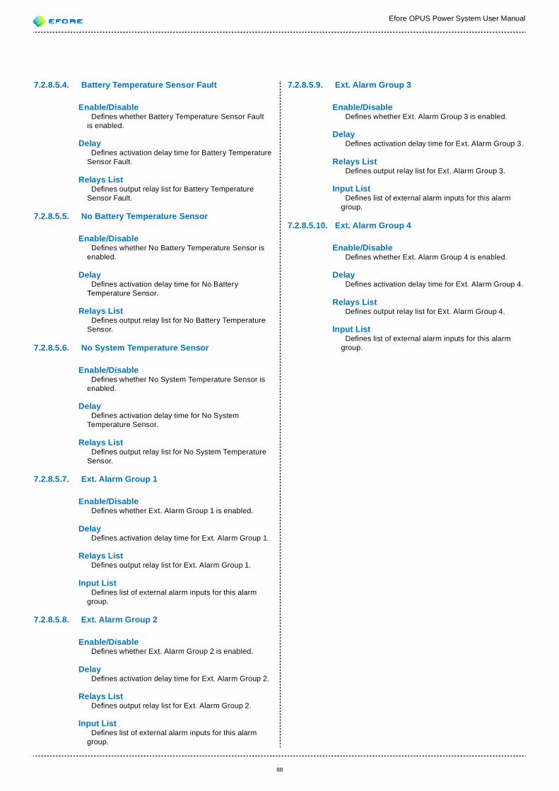
Efore OPUS Power System User Manual
88
7.2.8.5.4. Battery Temperature Sensor Fault
Enable/Disable De nes whether Battery Temperature Sensor Fault is enabled.
Delay De nes activation delay time for Battery Temperature Sensor Fault.
Relays List De nes output relay list for Battery Temperature Sensor Fault.
7.2.8.5.5. No Battery Temperature Sensor
Enable/Disable De nes whether No Battery Temperature Sensor is enabled.
Delay De nes activation delay time for No Battery Temperature Sensor.
Relays List De nes output relay list for No Battery Temperature Sensor.
7.2.8.5.6. No System Temperature Sensor
Enable/Disable De nes whether No System Temperature Sensor is enabled.
Delay De nes activation delay time for No System Temperature Sensor.
Relays List De nes output relay list for No System Temperature Sensor.
7.2.8.5.7. Ext. Alarm Group 1
Enable/Disable De nes whether Ext. Alarm Group 1 is enabled.
Delay De nes activation delay time for Ext. Alarm Group 1.
Relays List De nes output relay list for Ext. Alarm Group 1.
Input List De nes list of external alarm inputs for this alarm group.
7.2.8.5.8. Ext. Alarm Group 2
Enable/Disable De nes whether Ext. Alarm Group 2 is enabled.
Delay De nes activation delay time for Ext. Alarm Group 2.
Relays List De nes output relay list for Ext. Alarm Group 2.
Input List De nes list of external alarm inputs for this alarm group.
7.2.8.5.9. Ext. Alarm Group 3
Enable/Disable De nes whether Ext. Alarm Group 3 is enabled.
Delay De nes activation delay time for Ext. Alarm Group 3.
Relays List De nes output relay list for Ext. Alarm Group 3.
Input List De nes list of external alarm inputs for this alarm group.
7.2.8.5.10. Ext. Alarm Group 4
Enable/Disable De nes whether Ext. Alarm Group 4 is enabled.
Delay De nes activation delay time for Ext. Alarm Group 4.
Relays List De nes output relay list for Ext. Alarm Group 4.
Input List De nes list of external alarm inputs for this alarm group.
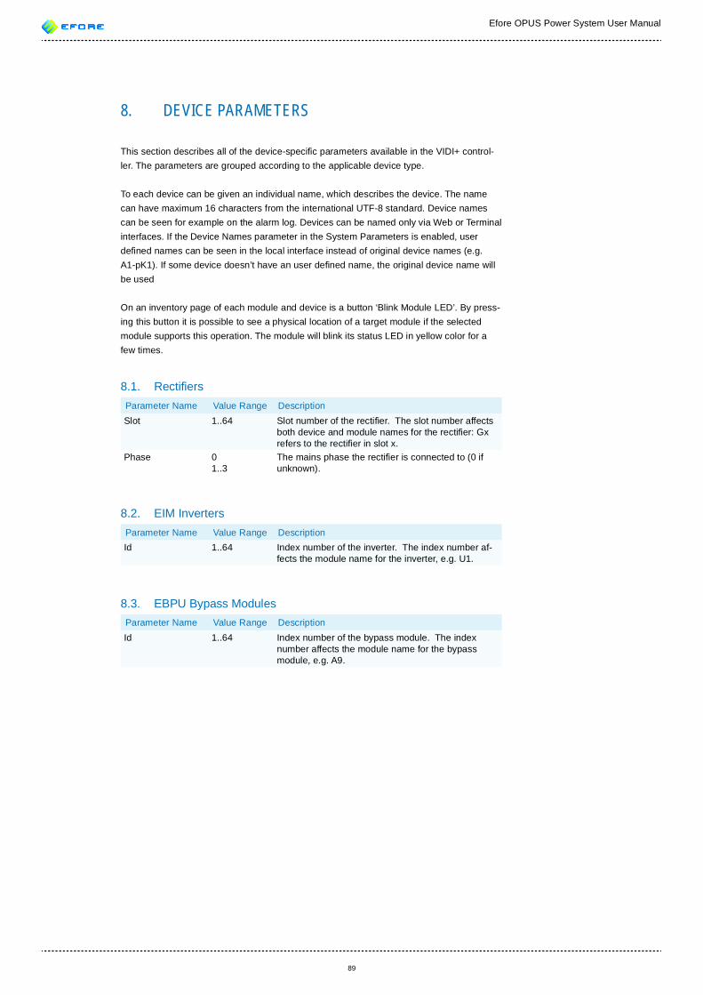
Efore OPUS Power System User Manual
89
8. DEVICE PARAMETERS
This section describes all of the device-speci c parameters available in the VIDI+ control-ler. The parameters are grouped according to the applicable device type.
To each device can be given an individual name, which describes the device. The name can have maximum 16 characters from the international UTF-8 standard. Device names can be seen for example on the alarm log. Devices can be named only via Web or Terminal interfaces. If the Device Names parameter in the System Parameters is enabled, user de ned names can be seen in the local interface instead of original device names (e.g. A1-pK1). If some device doesn’t have an user de ned name, the original device name will be used
On an inventory page of each module and device is a button ‘Blink Module LED’. By press-ing this button it is possible to see a physical location of a target module if the selected module supports this operation. The module will blink its status LED in yellow color for a few times.
8.1. Recti ersParameter Name Value Range DescriptionSlot 1..64 Slot number of the recti er. The slot number affects
both device and module names for the recti er: Gx refers to the recti er in slot x.
Phase 01..3
The mains phase the recti er is connected to (0 if unknown).
8.2. EIM InvertersParameter Name Value Range DescriptionId 1..64 Index number of the inverter. The index number af-
fects the module name for the inverter, e.g. U1.
8.3. EBPU Bypass ModulesParameter Name Value Range DescriptionId 1..64 Index number of the bypass module. The index
number affects the module name for the bypass module, e.g. A9.
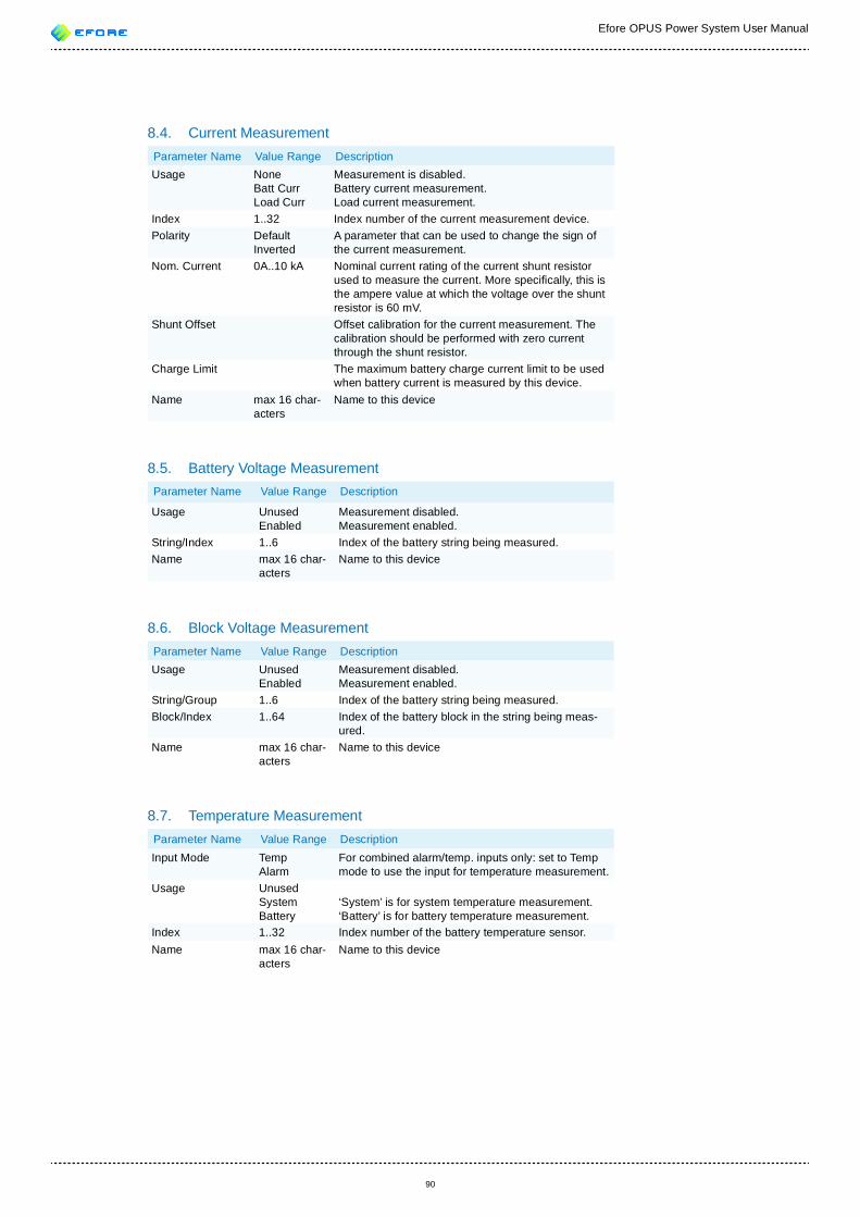
Efore OPUS Power System User Manual
90
8.4. Current MeasurementParameter Name Value Range DescriptionUsage None
Batt CurrLoad Curr
Measurement is disabled. Battery current measurement.Load current measurement.
Index 1..32 Index number of the current measurement device.Polarity Default
InvertedA parameter that can be used to change the sign of the current measurement.
Nom. Current 0A..10 kA Nominal current rating of the current shunt resistor used to measure the current. More speci cally, this is the ampere value at which the voltage over the shunt resistor is 60 mV.
Shunt Offset Offset calibration for the current measurement. The calibration should be performed with zero current through the shunt resistor.
Charge Limit The maximum battery charge current limit to be used when battery current is measured by this device.
Name max 16 char-acters
Name to this device
8.5. Battery Voltage MeasurementParameter Name Value Range Description
Usage UnusedEnabled
Measurement disabled.Measurement enabled.
String/Index 1..6 Index of the battery string being measured.Name max 16 char-
actersName to this device
8.6. Block Voltage MeasurementParameter Name Value Range DescriptionUsage Unused
EnabledMeasurement disabled.Measurement enabled.
String/Group 1..6 Index of the battery string being measured.Block/Index 1..64 Index of the battery block in the string being meas-
ured.Name max 16 char-
actersName to this device
8.7. Temperature MeasurementParameter Name Value Range DescriptionInput Mode Temp
Alarm For combined alarm/temp. inputs only: set to Temp mode to use the input for temperature measurement.
Usage UnusedSystemBattery
‘System’ is for system temperature measurement.‘Battery’ is for battery temperature measurement.
Index 1..32 Index number of the battery temperature sensor. Name max 16 char-
actersName to this device
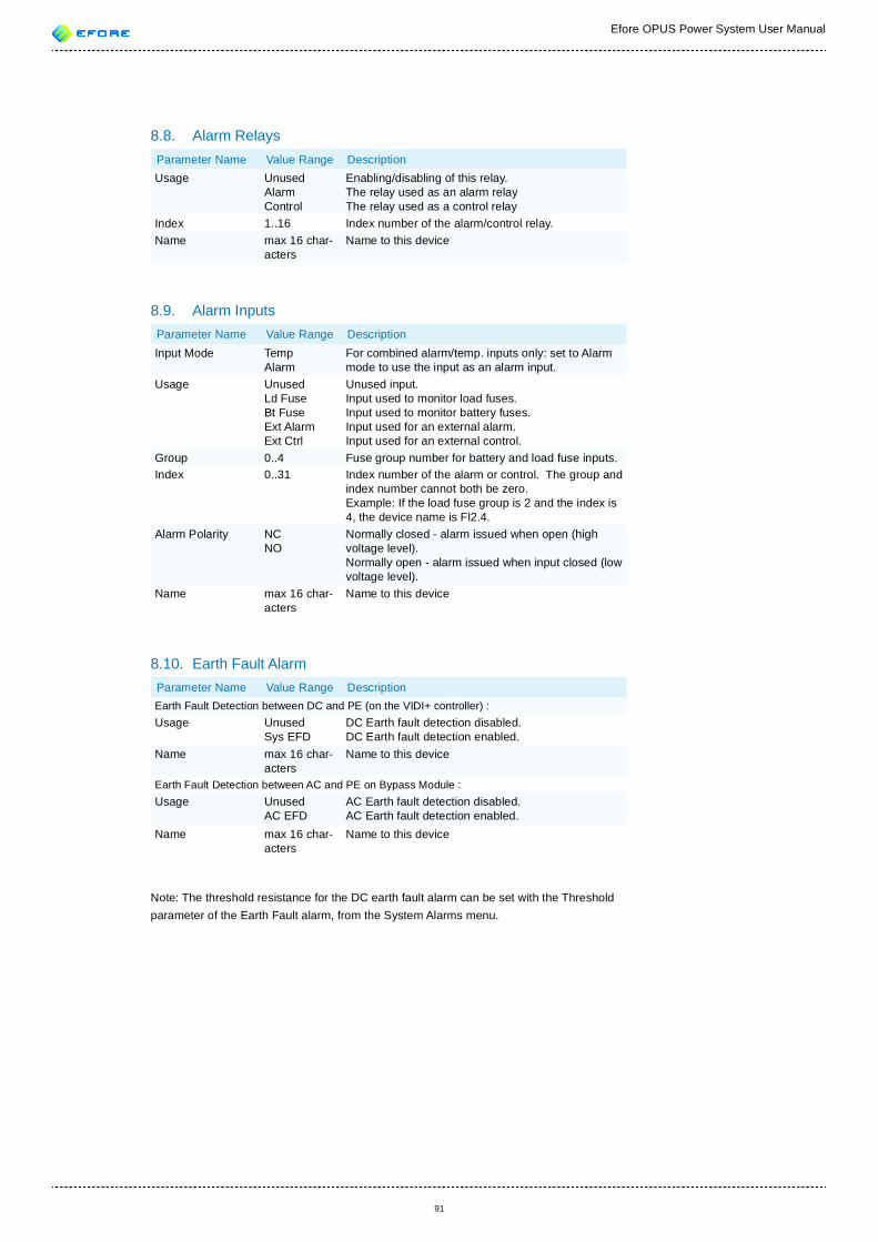
Efore OPUS Power System User Manual
91
8.8. Alarm RelaysParameter Name Value Range DescriptionUsage Unused
AlarmControl
Enabling/disabling of this relay.The relay used as an alarm relayThe relay used as a control relay
Index 1..16 Index number of the alarm/control relay.Name max 16 char-
actersName to this device
8.9. Alarm InputsParameter Name Value Range DescriptionInput Mode Temp
Alarm For combined alarm/temp. inputs only: set to Alarm mode to use the input as an alarm input.
Usage UnusedLd FuseBt FuseExt AlarmExt Ctrl
Unused input.Input used to monitor load fuses.Input used to monitor battery fuses.Input used for an external alarm.Input used for an external control.
Group 0..4 Fuse group number for battery and load fuse inputs.Index 0..31 Index number of the alarm or control. The group and
index number cannot both be zero. Example: If the load fuse group is 2 and the index is 4, the device name is Fl2.4.
Alarm Polarity NCNO
Normally closed - alarm issued when open (high voltage level).Normally open - alarm issued when input closed (low voltage level).
Name max 16 char-acters
Name to this device
8.10. Earth Fault AlarmParameter Name Value Range DescriptionEarth Fault Detection between DC and PE (on the VIDI+ controller) :Usage Unused
Sys EFDDC Earth fault detection disabled.DC Earth fault detection enabled.
Name max 16 char-acters
Name to this device
Earth Fault Detection between AC and PE on Bypass Module :Usage Unused
AC EFDAC Earth fault detection disabled.AC Earth fault detection enabled.
Name max 16 char-acters
Name to this device
Note: The threshold resistance for the DC earth fault alarm can be set with the Threshold parameter of the Earth Fault alarm, from the System Alarms menu.
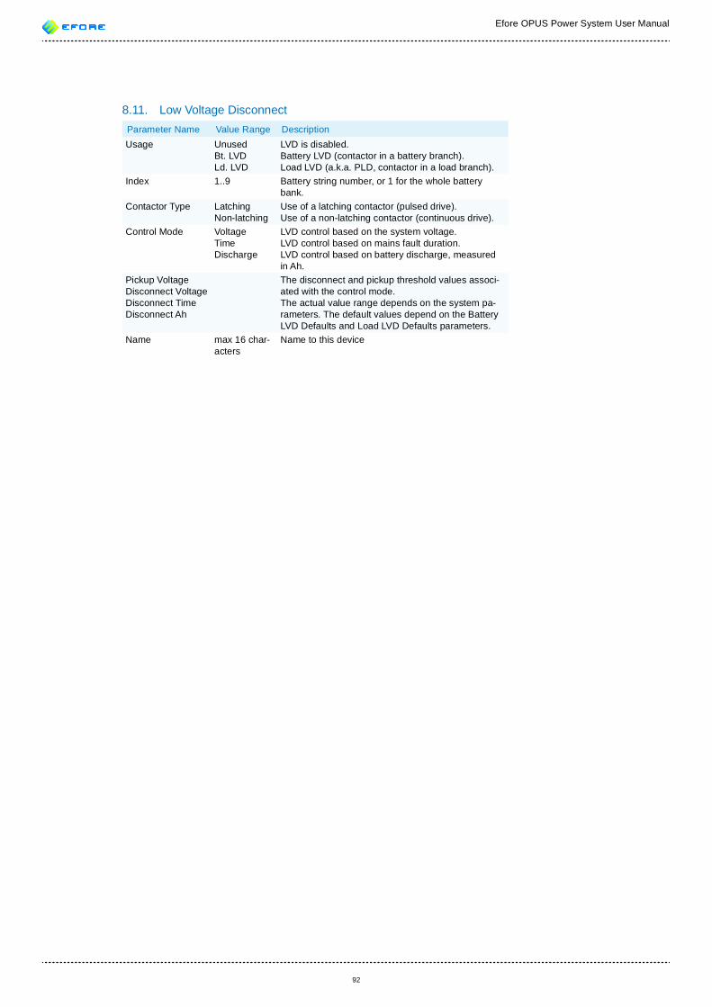
Efore OPUS Power System User Manual
92
8.11. Low Voltage Disconnect Parameter Name Value Range DescriptionUsage Unused
Bt. LVDLd. LVD
LVD is disabled.Battery LVD (contactor in a battery branch).Load LVD (a.k.a. PLD, contactor in a load branch).
Index 1..9 Battery string number, or 1 for the whole battery bank.
Contactor Type LatchingNon-latching
Use of a latching contactor (pulsed drive).Use of a non-latching contactor (continuous drive).
Control Mode VoltageTimeDischarge
LVD control based on the system voltage.LVD control based on mains fault duration.LVD control based on battery discharge, measured in Ah.
Pickup VoltageDisconnect VoltageDisconnect TimeDisconnect Ah
The disconnect and pickup threshold values associ-ated with the control mode. The actual value range depends on the system pa-rameters. The default values depend on the Battery LVD Defaults and Load LVD Defaults parameters.
Name max 16 char-acters
Name to this device
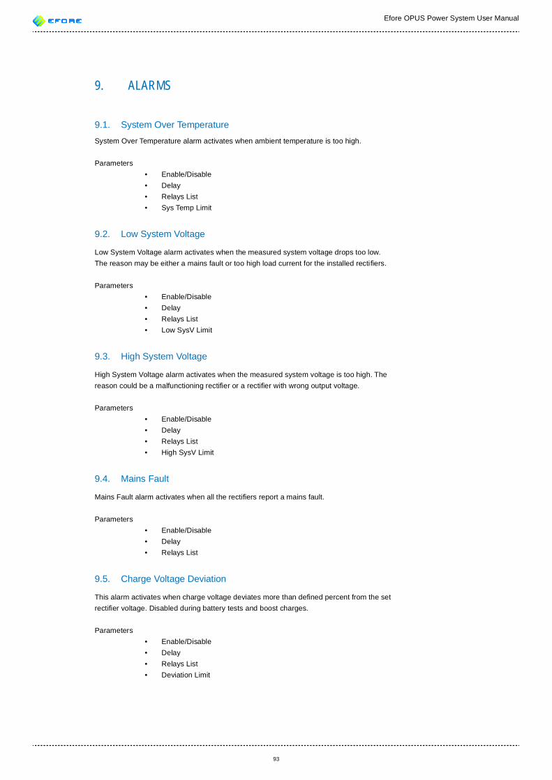
93
Efore OPUS Power System User Manual
9. ALARMS
9.1. System Over Temperature
System Over Temperature alarm activates when ambient temperature is too high.
Parameters • Enable/Disable • Delay • Relays List • Sys Temp Limit
9.2. Low System Voltage
Low System Voltage alarm activates when the measured system voltage drops too low. The reason may be either a mains fault or too high load current for the installed recti ers.
Parameters • Enable/Disable • Delay • Relays List • Low SysV Limit
9.3. High System Voltage
High System Voltage alarm activates when the measured system voltage is too high. The reason could be a malfunctioning recti er or a recti er with wrong output voltage.
Parameters • Enable/Disable • Delay • Relays List • High SysV Limit
9.4. Mains Fault
Mains Fault alarm activates when all the recti ers report a mains fault.
Parameters • Enable/Disable • Delay • Relays List
9.5. Charge Voltage Deviation
This alarm activates when charge voltage deviates more than de ned percent from the set recti er voltage. Disabled during battery tests and boost charges.
Parameters • Enable/Disable • Delay • Relays List • Deviation Limit
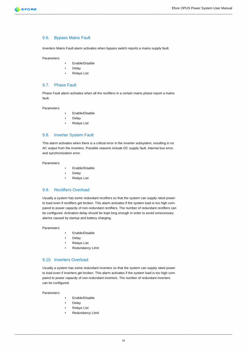
94
Efore OPUS Power System User Manual
9.6. Bypass Mains Fault
Inverters Mains Fault alarm activates when bypass switch reports a mains supply fault.
Parameters • Enable/Disable • Delay • Relays List
9.7. Phase Fault
Phase Fault alarm activates when all the recti ers in a certain mains phase report a mains fault.
Parameters • Enable/Disable • Delay • Relays List
9.8. Inverter System Fault
This alarm activates when there is a critical error in the inverter subsystem, resulting in no AC output from the inverters. Possible reasons include DC supply fault, internal bus error, and synchronization error.
Parameters • Enable/Disable • Delay • Relays List
9.9. Recti ers Overload
Usually a system has some redundant recti ers so that the system can supply rated power to load even if recti ers get broken. This alarm activates if the system load is too high com-pared to power capacity of non-redundant recti ers. The number of redundant recti ers can be con gured. Activation delay should be kept long enough in order to avoid unnecessary alarms caused by startup and battery charging.
Parameters • Enable/Disable • Delay • Relays List • Redundancy Limit
9.10. Inverters Overload
Usually a system has some redundant inverters so that the system can supply rated power to load even if inverters get broken. This alarm activates if the system load is too high com-pared to power capacity of non-redundant inverters. The number of redundant inverters can be con gured.
Parameters • Enable/Disable • Delay • Relays List • Redundancy Limit
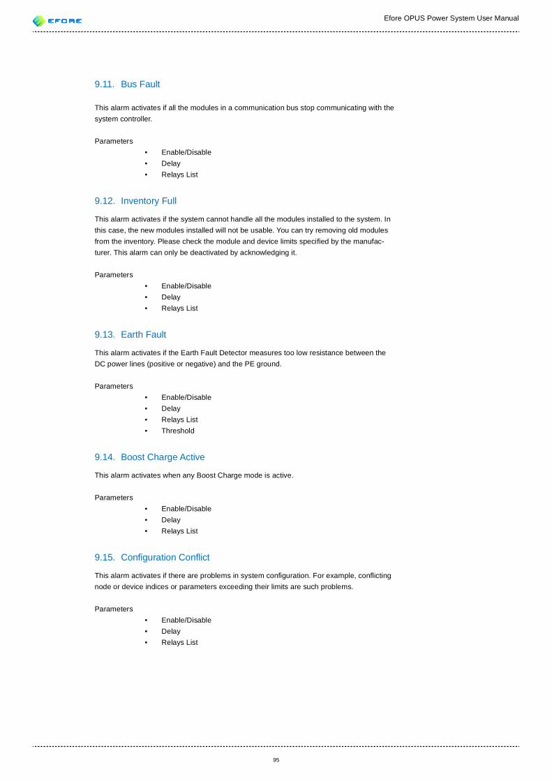
95
Efore OPUS Power System User Manual
9.11. Bus Fault
This alarm activates if all the modules in a communication bus stop communicating with the system controller.
Parameters • Enable/Disable • Delay • Relays List
9.12. Inventory Full
This alarm activates if the system cannot handle all the modules installed to the system. In this case, the new modules installed will not be usable. You can try removing old modules from the inventory. Please check the module and device limits speci ed by the manufac-turer. This alarm can only be deactivated by acknowledging it.
Parameters • Enable/Disable • Delay • Relays List
9.13. Earth Fault
This alarm activates if the Earth Fault Detector measures too low resistance between the DC power lines (positive or negative) and the PE ground.
Parameters • Enable/Disable • Delay • Relays List • Threshold
9.14. Boost Charge Active
This alarm activates when any Boost Charge mode is active.
Parameters • Enable/Disable • Delay • Relays List
9.15. Con guration Con ict
This alarm activates if there are problems in system con guration. For example, con icting node or device indices or parameters exceeding their limits are such problems.
Parameters • Enable/Disable • Delay • Relays List
96
Efore OPUS Power System User Manual
9.16. Recti er Fault
The self-diagnostics of a recti er module indicate that the recti er module is faulty and should be replaced. In some cases a cold restart of the recti er module may x the prob-lem.
Parameters • Enable/Disable • Delay • Relays List
9.17. Recti er Over Voltage
Recti er module reports too high DC voltage. The recti er may require cold restart to recover from the fault.
Parameters • Enable/Disable • Delay • Relays List
9.18. Recti er Over Temperature
Recti er module reports too high internal temperature. The ambient temperature may be too high.
Parameters • Enable/Disable • Delay • Relays List
9.19. Recti er Mains Fault
Recti er module reports either too low or high Mains Voltage.
Parameters • Enable/Disable • Delay • Relays List
9.20. Recti er Wrong Voltage Version
The alarm is activated if any recti er in the system has different voltage group than the value of Recti ers Voltage Group parameter.
Parameters • Enable/Disable • Delay • Relays List
9.21. Communication Error
System Controller is unable to communicate with a system module. This can happen if the module has been disconnected from the bus, removed from the system or is faulty.
Parameters • Enable/Disable • Delay • Relays List
97
Efore OPUS Power System User Manual
9.22. Module Fault
The self-diagnostics of a system module indicate that the module is faulty and should be replaced. In some cases a cold restart of the module may x the problem.
Parameters • Enable/Disable • Delay • Relays List
9.23. Inverter Fault
An inverter module reports a critical fault in the module itself.
Parameters • Enable/Disable • Delay • Relays List
9.24. Bypass Fault
Bypass module reports a critical fault in the module itself.
Parameters • Enable/Disable • Delay • Relays List
9.25. NvRam Fault
Module reports a NVRAM fault in the module itself.
Parameters • Enable/Disable • Delay • Relays List
9.26. Con g Fault
Some of module con guration is missing.
Parameters • Enable/Disable • Delay • Relays List
9.27. Bad Firmware
Module has a bad rmware and it should be updated.
Parameters • Enable/Disable • Delay • Relays List
98
Efore OPUS Power System User Manual
9.28. Automatic Boost Charge Fault
Automatic Boost Charge Fault is activated if ABC Time Limit is exceeded before battery charge current drops below Stop Current.
Parameters • Enable/Disable • Delay • Relays List
9.29. Battery Test Fault
Battery Test Fault is activated if battery voltage drops below Stop Voltage before the Bat-tery Test Time Limit or Discharge Limit is exceeded.
Parameters • Enable/Disable • Delay • Relays List
9.30. Battery Block Low Voltage
This alarm activates if a battery block voltage is measured to be below the con gured limit.
Parameters • Enable/Disable • Delay • Relays List • Low BlockV Limit
9.31. Battery Block High Voltage
This alarm activates if a battery block voltage is measured to be above the con gured limit.
Parameters • Enable/Disable • Delay • Relays List • High BlockV Limit
9.32. Battery Over Temperature
This alarm activates if any of the battery temperature sensors indicate that battery tempera-ture is above the con gured limit.
Parameters • Enable/Disable • Delay • Relays List • Battery Temp Limit
99
Efore OPUS Power System User Manual
9.33. Battery String Asymmetry
This alarm activates if voltage measurement of any of the battery block in a battery string differs too much from the average block voltage in the battery string.
Parameters • Enable/Disable • Delay • Relays List • Asymmetry Limit
9.34. Load LVD Disconnect Warning
This alarm warns that a Load LVD may be disconnecting shortly. The user may con gure voltage, time or discharge margin from the warning to the disconnect point.
Parameters • Enable/Disable • Delay • Relays List • Ld LVD Warn. Voltage Margin • Ld LVD Warn. Time Margin • Ld LVD Warn. Discharge Margin
9.35. Load LVD Disconnect Imminent
This alarm warns that a Load LVD is about to disconnect in about ten seconds.
Parameters • Enable/Disable • Delay • Relays List
9.36. Battery LVD Disconnect Warning
This alarm warns that a Battery LVD may be disconnecting shortly. The user may con gure voltage, time or discharge margin from the warning to the disconnect point.
Parameters • Enable/Disable • Delay • Relays List • Bt LVD Warn. Voltage Margin • Bt LVD Warn. Time Margin • Bt LVD Warn. Discharge Margin
9.37. Battery LVD Disconnect Imminent
This alarm warns that a Battery LVD is about to disconnect in about ten seconds. This will most likely shut down the system.
Parameters • Enable/Disable • Delay • Relays List
100
Efore OPUS Power System User Manual
9.38. Contactor Fault
Load or Battery LVD contactor is not responding to control commands. Either the contactor if faulty or the feedback signal from the aux contacts is invalid.
Parameters • Enable/Disable • Delay • Relays List
9.39. Battery Fuse Fault
A battery fuse has tripped.
Parameters • Enable/Disable • Delay • Relays List
9.40. Load Fuse Fault
A load fuse has tripped.
Parameters • Enable/Disable • Delay • Relays List
9.41. Current Shunt Fault
This alarm activates if a current shunt is not properly con gured or the current measure-ment is not inside reasonable limits.
Parameters • Enable/Disable • Delay • Relays List
9.42. Battery Temperature Sensor Fault
A battery temperature measurement is not inside reasonable limits. The sensor or sensor cables are likely to be damaged.
Parameters • Enable/Disable • Delay • Relays List
9.43. No Battery Temperature Sensor
Battery Temperature Compensation feature is enabled but there is no battery temperature sensor.
Parameters • Enable/Disable • Delay • Relays List
101
Efore OPUS Power System User Manual
9.44. No System Temperature Sensor
This alarm activates if there is no system temperature sensor available.
Parameters • Enable/Disable • Delay • Relays List
9.45. Ext. Alarm Group 1
An external alarm connected to external alarm group 1 is active.
Parameters • Enable/Disable • Delay • Relays List • Input List
9.46. Ext. Alarm Group 2
An external alarm connected to external alarm group 2 is active.
Parameters • Enable/Disable • Delay • Relays List • Input List
9.47. Ext. Alarm Group 3
An external alarm connected to external alarm group 3 is active.
Parameters • Enable/Disable • Delay • Relays List • Input List
9.48. Ext. Alarm Group 4
An external alarm connected to external alarm group 4 is active.
Parameters • Enable/Disable • Delay • Relays List • Input List
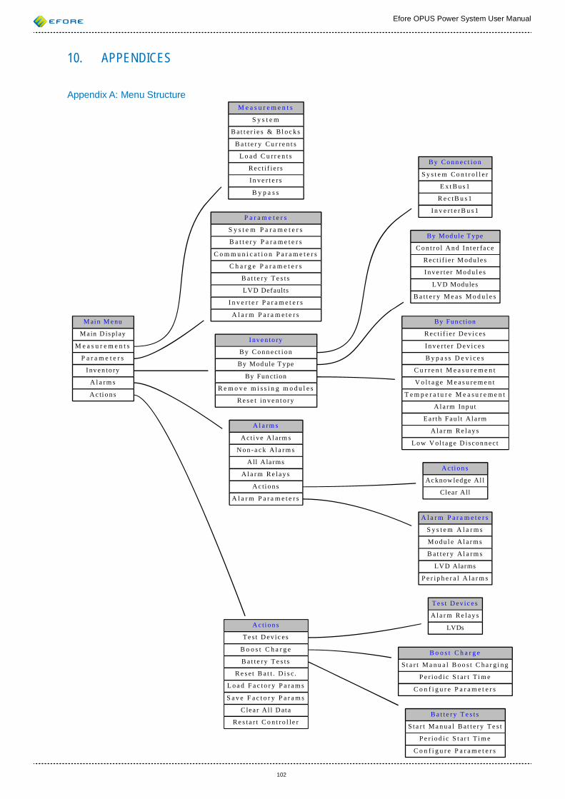
Efore OPUS Power System User Manual
102
10. APPENDICES
Appendix A: Menu Structure
M ain M enu
Main D ispl ay
M e a s u r e m e n t s
P a r a m e t e r s
I nv e n to ry
A l a rm s
A c ti o n s
M e a s u r e m e n t s
S y s t e m
B a t t e r i e s & Bl o c k s
B a t t e r y C u r r e n t s
L o a d C u r r e n t s
Rec t i f i e rs
I n v e r t e r s
B y p a s s
P a r a m e t e r s
S y s t e m P a r a m e t e r s
B a t t e r y P a r a m e t e r s
C o m m u n i c a t i o n P a r a m e t e r s
C h a r g e P a r a m e t e r s
B a t t e r y T e s t s
LVD Defaults
I n v e r t e r P a r a m e t e r s
A l a r m P a r a m e t e r s
I nv e n to ry
B y C o n n e c t i o n
By Mod ule T ype
By Fun ct ion
R e m o v e m i s s i n g m o d u l e s
R e s e t in v e n t o r y
A l a rm s
Ac t ive A la rm s
N o n - a c k A l a r m s
All A la rms
A l a r m R e l a y s
A c ti o n s
A l a r m P a r a m e t e r s
A c ti o n s
Te s t D ev ic es
B o o s t C h a r g e
B a t t e r y T e s t s
R e s e t B a t t . D i s c .
L o a d F a c to r y P a ra m s
S a v e F a c t o r y P a r a m s
Clea r Al l D ata
R e s ta r t C o n t r o l l e r
B y C o n n e c t i o n
S y s t e m Co n t r o l l e r
E x t B u s 1
R e c tB u s 1
I n v e r t e r B u s 1
By Mod ule T ype
C o n t r o l A n d I n t e r fa c e
Rec t i f i e r M odu le s
I n v e r t e r M o d u l e s
LVD Modules
B a t t e r y M e a s M o d u l e s
By Fun ct ion
Rec t i f i e r Dev ices
I n v e r t e r D e v i c e s
B y p a s s D e v i c e s
C u r r e n t M e a s u r e m e n t
V o l t a g e M e a s u r e m e n t
T e m p e r a t u r e M e a s u r e m e n t
A l a rm In p ut
Ea r th Fau l t A la rm
A l a r m R e l a y s
Low V o l t ag e D i sconn ec t
A c ti o n s
Ac know ledge Al l
Clear All
A l a r m P a r a m e t e r s
S y s t e m A l a r m s
M o d u l e A l a r m s
B a t t e r y A l a r m s
LVD Alarms
P e r ip h e r a l A la r m s
Te s t D ev ic es
A l a r m R e l a y s
LVDs
B o o s t C h a r g e
S t a r t M a n u a l B o o s t C h a r g i n g
P e r io d i c S t a r t T i m e
C o n f i g u r e P a r a m e t e r s
B a t t e r y T e s t s
S t a r t M a n u a l B at t e r y T e s t
P e r io d i c S t a r t T i m e
C o n f i g u r e P a r a m e t e r s
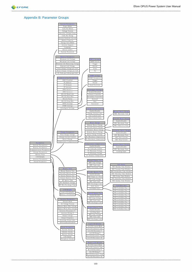
Efore OPUS Power System User Manual
103
Appendix B: Parameter Groups
P a r a m e t e r s
S y s t e m P a r a m e t e r s
B a t t e r y P a r a m e t e r s
C o m m u n i c a t i o n P a r a m e t e r s
C h a r g e P a r a m e t e r s
B a t t er y Te s t s
LVD Def ault s
I n v e r t e r P a r a m e t e r s
A l a r m P a r a m e t e r s
S y s t e m P a r a m e t e r s
E xp e r t Mo d e
Ce l ls P er B lo c k
Vol t age Ver si on
Re ct i fi er Vo lt a ge Gr ou p
C el l s Pe r St r i n g
S y s t e m N o mi n a l Cu r r e n t
B at t e r y Ca p a ci t y
E n e r g y S a v e Mo d e
I n v e r t e r S u p p o r t
L a n g u a g e
D e v i c e n a m e s
S y s t e m P a s s w o r d
B a t t e r y P a r a m e t e r s
Mi nimu m Cel l V olt ag e
Max im um C el l Vo lt ag e
Min imu m Cel l Mon itoring Vo lt age
Nom ina l Ce ll Vol ta ge
F lo a t Ch ar g e Vo l ta g e pe r Ce l l
B oo s t C h ar g e V o lt a g e p e r C el l
TC Vo lt s pe r C el ci u s p er Ce l l
C o m m u n i c a t i o n P a r a m e t e r s
DHC P E na bl ed
I P A d d r e s s
I P N e t ma s k
I P Ga te wa y
D NS S e r v e r 1
D NS S e r v e r 2
R S - 2 3 2 B a u d r a t e
R S- 2 32 D at a B i t s
RS -2 32 Pa ri t y
R S- 2 3 2 St o p B i ts
S MT P S e t ti n g s
S NMP S et t i n gs
E c h oA g e n t S e t t i n g s
C h a r g e P a r a m e t e r s
F lo a t Ch a rg e Vo l t ag e
C h a r g e C u r r e n t Co n t ro l
B o o s t C h a r g e
T e m p e r a t u r e C o m p e n s a t io n
B a t t er y Te s t s
Ma n ua l B at t e ry T es t
P er i od i c Ba t t er y Te s t
Na t u r al Ba t t er y T es t
R e mo t e B a t t e r y T es t
BT I gn o re T im e
BT S hu t do wn V ol t a ge
B T M i n Pr e c ha r ge Ti me
LVD Def ault s
Loa d LVD Defa ult s
Bat te ry L VD Def aul ts
I n v e r t e r P a r a m e t e r s
De f au l t Mo de
AC Vo lta ge Ve rsi on
By p as s Ma in s Mi n Vol t a ge
B yp a s s Ma i ns Ma x Vo l t a ge
I n ve r t er s D i s co n ne c t V
I nv er t er s Pi c ku p V
Ou tp ut V ol ta ge
O ut p u t F re q u en c y
Ov e rt e mp Al a rm L im it
EF D E na bl e d/ Di sa bl e d
A l a r m P a r a m e t e r s
S y s t e m A l a r m s
Mo d ul e A la r ms
B a t t e r y A l a r ms
LVD Alarms
P e r i p h e r a l A l a r m s
S MT P S e t ti n g s
S MT P S er v e r
Tri gger
P e ri o d
Fr o m
To
S NMP S et t i n gs
S N M P P a r a m e t e r s
Tri gger
P e ri o d
S e n d O v e r v i e w
E c h oA g e n t S e t t i n g s
E n a bl e d / D i s a b l e d
P ri m ar y C on t ro l l er
S e c on d a r y C o n t r o l l e r
P ro t o co l
Po r t
P a s s w o r d
C h a r g e C u r r e n t Co n t ro l
E na b l e /D i s a bl e
C ha r ge Cu r re n t L i mi t
F as t C o nt r o l Ga i n
S lo w Co n t ro l G ai n
B o o s t C h a r g e
M a n u a l B o o s t C h a r g e
P e r i o d i c B o o s t C h a r g e
A u t o m a t i c B o o s t C h a r g e
R e m o t e B o o s t C h a r g e
B oo s t Ch a r g e V o l t ag e
B C Mi n imu m T e mp e ra t u r e
B C M a x i mu m T em p e r a tu r e
T e m p e r a t u r e C o m p e n s a t io n
E na b l e /D i s a bl e
TC V ol t s pe r Ce l si u s
TC Maxi mum Vol ta ge
TC Mi ni mum Vol ta ge
T C No mi n a l T em pe r a t ur e
M a n u a l B o o s t C h a r g e
MBC Max i mum Time
P e r i o d i c B o o s t C h a r g e
E na b l e /D i s a bl e
P BC Ma x i mu m Time
P BC T im e s i n a Ye a r
A u t o m a t i c B o o s t C h a r g e
E na b l e /D i s a bl e
AB C Ma xi mu m T im e
A BC S t ar t Cu r r en t
AB C St o p Cu r r en t
R e m o t e B o o s t C h a r g e
E na b l e /D i s a bl e
RB C M ax i mum Ti m e
La tc hi ng I np ut
Ma n ua l B at t e ry T es t
MBT St op Vo lt age
MBT Time Limit
MBT D isc har ge Limi t
P er i od i c Ba t t er y Te s t
E na b l e /D i s a bl e
P BT Tim es i n a Ye a r
PB T S t op Vol t ag e
PBT Ti me Limi t
PB T D is c ha rg e Li mi t
S a f e h o u r s
F o r b i d d e n d a y s
Na t u r al Ba t t er y T es t
E na b l e /D i s a bl e
NB T St o p Vo lt a ge
NBT Time Limit
NBT Dis ch arg e L imi t
R e mo t e B a t t e r y T es t
E na b l e /D i s a bl e
La tc hi ng I np ut
RBT St op Vol ta ge
RBT Time Limit
RB T Di sc ha rge Li mi t
S a f e h o u r s
PB T Mon day Tim e Win do w
PB T T ue s da y T im e W in do w
PB T W ed ne sd ay Ti me Wi n do w
P BT Th u rs d ay T im e Wi nd ow
PBT F rid ay Ti me Windo w
P BT Sa t ur d ay Ti m e W in d ow
P BT Su n da y Ti me W in d ow
F o r b i d d e n d a y s
P BT Fo r bi d de n Da y 1
P BT Fo r bi d de n Da y 2
P BT Fo r bi d de n Da y 3
P BT Fo r bi d de n Da y 4
P BT Fo r bi d de n Da y 5
P BT Fo r bi d de n Da y 6
P BT Fo r bi d de n Da y 7
P BT Fo r bi d de n Da y 8
P BT Fo r bi d de n Da y 9
P BT Fo r bi d d en D ay 1 0
Loa d LVD Defa ult s
Ld LVD Control Mode
Ld LVD Cont actor Type
Ld LVD Disconnect V
Ld LVD Pickup V
Ld LVD Di scon nect Time
Ld LVD Dis connect Ah
Bat te ry L VD Def aul ts
Bt LVD Contro l Mode
Bt LVD Contact or Type
Bt LVD Di sconnect V
Bt LVD Pickup V
Bt LVD Di sc onn ec t Ti me
Bt LVD Disconne ct Ah
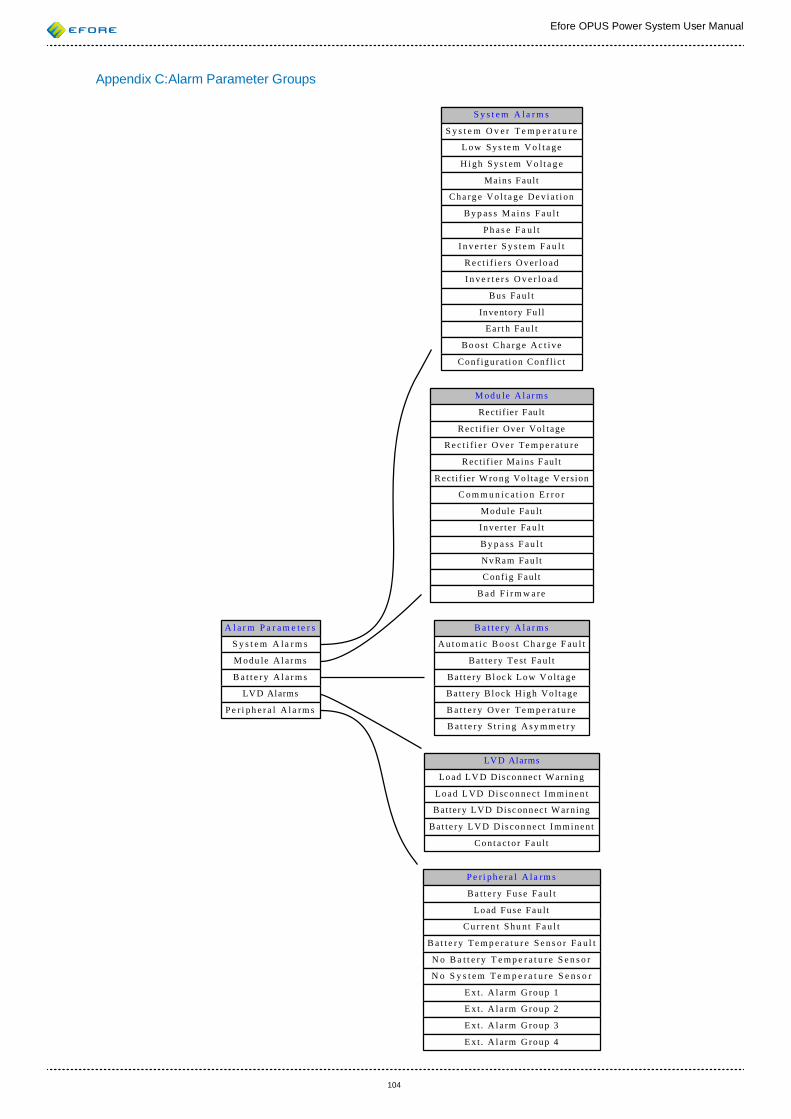
Efore OPUS Power System User Manual
104
Appendix C:Alarm Parameter Groups
A l a r m P a r a m e t e r s
S y s t e m A la r m s
M odu le A l a r ms
B a t t e r y A l a r m s
LVD Alarms
P e r i ph e r a l A l a rm s
S y s t e m A la r m s
S y s t e m O v e r T e m p e r a t u r e
L ow Sys te m V o l t a ge
H i gh S ys t em V o lt a g e
Mains F aul t
Cha rg e Vo l t a ge De v i a t i on
B y p as s M a i n s F a u l t
P h a s e F a u l t
I n v e r t e r S y s t e m F a u l t
R e ct i f i e r s O v er l o ad
I n v e r t e r s O v e r lo a d
Bus Fau l t
Invento ry Fu l l
Ear t h Fau l t
Bo os t C ha rg e Ac t i ve
Conf igu rat i on Conf l i c t
M odu le A l a r ms
Recti f ie r Fau lt
Rect i f ie r Over Vol tage
R e c t i f i e r O ve r Te m p e r at u re
R ect i f ier Mains F aul t
R ect i f ier W ro ng Vo ltag e V er sion
C o m m u n i c a t i o n E r r o r
Modul e Fau lt
Inve r t e r Fa u l t
B y p a ss F au l t
NvRam Fau lt
C onfi g F aul t
B a d F i r m w a re
B a t t e r y A l a r m s
A u t o m a t i c B o o s t Ch a r g e F au l t
B at te ry Te st Fa u l t
Ba tt e ry B l oc k Low V oltage
Ba tt e ry B lock High Vo lt age
B a t t e r y O v e r T e m p e r a t u r e
B at t e r y S t r i n g A s y mm e t r y
LVD Alarms
Load LV D Disconnect Warnin g
Load L VD Di sc onnec t Imm inen t
B at ter y LVD Disc onnect W arn ing
Ba t t e ry LV D D iscon nect Imminen t
Con t a c to r Fa u l t
P e r i ph e r a l A l a rm s
Ba t t e ry Fus e Fa u l t
Load Fuse Fau l t
C u r re n t S hu n t F a u l t
B a t t e r y T e m p e r a t u r e S e n s o r Fa u l t
N o B a t t e r y T e m p e r a t u r e S e n s o r
N o S y s t e m T e m p e r a t u r e S e n s o r
E x t . A l a rm G roup 1
E x t . A l a rm G roup 2
E x t . A l a rm G roup 3
E x t . A l a rm G roup 4