vpn client administrator guide - cisco.com · this vpn client administrator guide tells you how to...
TRANSCRIPT

VPN Client Administrator GuideRelease 4.6August 2004
Corporate HeadquartersCisco Systems, Inc.170 West Tasman DriveSan Jose, CA 95134-1706 USAhttp://www.cisco.comTel: 408 526-4000
800 553-NETS (6387)Fax: 408 526-4100
Text Part Number: OL-5492-01

THE SPECIFICATIONS AND INFORMATION REGARDING THE PRODUCTS IN THIS MANUAL ARE SUBJECT TO CHANGE WITHOUT NOTICE. ALL STATEMENTS, INFORMATION, AND RECOMMENDATIONS IN THIS MANUAL ARE BELIEVED TO BE ACCURATE BUT ARE PRESENTED WITHOUT WARRANTY OF ANY KIND, EXPRESS OR IMPLIED. USERS MUST TAKE FULL RESPONSIBILITY FOR THEIR APPLICATION OF ANY PRODUCTS.
THE SOFTWARE LICENSE AND LIMITED WARRANTY FOR THE ACCOMPANYING PRODUCT ARE SET FORTH IN THE INFORMATION PACKET THAT SHIPPED WITH THE PRODUCT AND ARE INCORPORATED HEREIN BY THIS REFERENCE. IF YOU ARE UNABLE TO LOCATE THE SOFTWARE LICENSE OR LIMITED WARRANTY, CONTACT YOUR CISCO REPRESENTATIVE FOR A COPY.
The Cisco implementation of TCP header compression is an adaptation of a program developed by the University of California, Berkeley (UCB) as part of UCB’s public domain version of the UNIX operating system. All rights reserved. Copyright © 1981, Regents of the University of California.
NOTWITHSTANDING ANY OTHER WARRANTY HEREIN, ALL DOCUMENT FILES AND SOFTWARE OF THESE SUPPLIERS ARE PROVIDED “AS IS” WITH ALL FAULTS. CISCO AND THE ABOVE-NAMED SUPPLIERS DISCLAIM ALL WARRANTIES, EXPRESSED OR IMPLIED, INCLUDING, WITHOUT LIMITATION, THOSE OF MERCHANTABILITY, FITNESS FOR A PARTICULAR PURPOSE AND NONINFRINGEMENT OR ARISING FROM A COURSE OF DEALING, USAGE, OR TRADE PRACTICE.
IN NO EVENT SHALL CISCO OR ITS SUPPLIERS BE LIABLE FOR ANY INDIRECT, SPECIAL, CONSEQUENTIAL, OR INCIDENTAL DAMAGES, INCLUDING, WITHOUT LIMITATION, LOST PROFITS OR LOSS OR DAMAGE TO DATA ARISING OUT OF THE USE OR INABILITY TO USE THIS MANUAL, EVEN IF CISCO OR ITS SUPPLIERS HAVE BEEN ADVISED OF THE POSSIBILITY OF SUCH DAMAGES.
VPN Client Administrator GuideCopyright © 2004 Cisco Systems, Inc.All rights reserved.
CCIP, CCSP, the Cisco Arrow logo, the Cisco Powered Network mark, Cisco Unity, Follow Me Browsing, FormShare, and StackWise are trademarks of Cisco Systems, Inc.; Changing the Way We Work, Live, Play, and Learn, and iQuick Study are service marks of Cisco Systems, Inc.; and Aironet, ASIST, BPX, Catalyst, CCDA, CCDP, CCIE, CCNA, CCNP, Cisco, the Cisco Certified Internetwork Expert logo, Cisco IOS, the Cisco IOS logo, Cisco Press, Cisco Systems, Cisco Systems Capital, the Cisco Systems logo, Empowering the Internet Generation, Enterprise/Solver, EtherChannel, EtherSwitch, Fast Step, GigaStack, Internet Quotient, IOS, IP/TV, iQ Expertise, the iQ logo, iQ Net Readiness Scorecard, LightStream, MGX, MICA, the Networkers logo, Networking Academy, Network Registrar, Packet, PIX, Post-Routing, Pre-Routing, RateMUX, Registrar, ScriptShare, SlideCast, SMARTnet, StrataView Plus, Stratm, SwitchProbe, TeleRouter, The Fastest Way to Increase Your Internet Quotient, TransPath, and VCO are registered trademarks of Cisco Systems, Inc. and/or its affiliates in the U.S. and certain other countries.
All other trademarks mentioned in this document or Web site are the property of their respective owners. The use of the word partner does not imply a partnership relationship between Cisco and any other company. (0304R)

OL-5492-01
C O N T E N T S
About This Guide ix
Audience ix
Organization x
Related Documentation xi
VPN 3000 Series Concentrator Documentation xi
Other References xi
Conventions xii
Data Formats xii
Obtaining Documentation xiii
Cisco.com xiii
Documentation CD-ROM xiii
Ordering Documentation xiii
Documentation Feedback xiv
Obtaining Technical Assistance xiv
Cisco.com xiv
Technical Assistance Center xv
Cisco TAC Website xv
Cisco TAC Escalation Center xv
Obtaining Additional Publications and Information xvi
C H A P T E R 1 Configuration Information for an Administrator 1-1
VPN 3000 Series Concentrators Configuration Information 1-1
Configuring a VPN 3000 Concentrator for Remote Access Users 1-1
Completing Quick Configuration 1-2
Creating an IPSec Group 1-2
Creating VPN Client User Profiles 1-3
Configuring VPN Client Users for Digital Certificate Authorization 1-3
Connecting with Digital Certificates 1-5
Configuring VPN Client Firewall Policy—Windows Only 1-5
Overview 1-5
Firewall Configuration Scenarios 1-8
Defining a Filter and Rules to Use with Firewalls for CPP 1-10
Configuring the VPN 3000 Concentrator to Enforce Firewall Usage on the VPN Client 1-11
Setting up Cisco Integrated Client Firewall (CIC) for CPP 1-11
iiiVPN Client Administrator Guide

Contents
Custom Vendor Codes 1-12
Obtaining Firewall Troubleshooting Information 1-12
Notifying Remote Users of a Client Update—All VPN Client Platforms 1-13
Setting up Local LAN Access for the VPN Client 1-14
Configuring the VPN Concentrator for Client Backup Servers 1-16
Configuring NAT Traversal for the VPN Client 1-16
Global Configuration 1-16
Configuring Automatic Browser Configuration—Windows Only 1-17
Configuring Entrust Entelligence for the VPN Client—Windows Only 1-18
Setting up the VPN Client for Authentication using Smart Cards—Windows Only 1-20
Configuring Mutual Authentication 1-20
Configuring Mutual Group Authentication on the VPN Client System 1-20
Configuring Mutual Authentication on the VPN Concentrator 1-21
C H A P T E R 2 Preconfiguring the VPN Client for Remote Users 2-1
User Profiles 2-1
File Format for All Profile Files 2-2
Making a Parameter Read Only 2-2
Creating a Global Profile 2-2
Features Controlled by Global Profile 2-2
Global Profile Configuration Parameters 2-4
Creating and Using a Default User Profile 2-13
DNS Suffixes and the VPN Client—Windows 2000 and Windows XP Only 2-13
Setting Up RADIUS SDI Extended Authentication 2-16
Creating Connection Profiles 2-17
Features Controlled by Connection Profiles 2-17
Creating a .pcf file for a Connection Profile 2-19
Naming the Connection Profile 2-19
Connection Profile Configuration Parameters 2-20
Distributing Configured VPN Client Software to Remote Users 2-26
Separate Distribution 2-26
Distribution with the VPN Client Software 2-27
C H A P T E R 3 Updating VPN Client Software 3-1
Enabling Client Update (All Client Types) 3-1
Updating the VPN Client Software Automatically on Windows 2000 and Windows XP Systems 3-2
ivVPN Client Administrator Guide
OL-5492-01

Contents
Managing Autoupdates 3-3
Prerequisite 3-3
Enabling Client Update for Automatic Updates 3-3
Getting the Updated Software from Cisco Systems 3-4
Creating the New Update Configuration File 3-6
new_update_config.ini File Keywords and Values 3-6
Creating the Profile Distribution Package 3-7
How Automatic Update Works 3-8
C H A P T E R 4 Configuring Automatic VPN Initiation 4-1
Creating Automatic VPN Initiation in the vpnclient.ini File 4-3
Preparation 4-3
What You Have to Do 4-3
Verifying Automatic VPN Initiation Configuration 4-5
C H A P T E R 5 Using the VPN Client Command-Line Interface 5-1
CLI Commands 5-1
Displaying a List of VPN Client Commands 5-1
Starting a Connection—vpnclient connect 5-2
Displaying a Notification—vpnclient notify 5-4
Displaying an Automatic VPN Initiation Configuration—Windows Only 5-5
Suspending/Resuming Stateful Firewall (Windows Only) 5-5
Ending a Connection—vpnclient disconnect 5-6
Displaying Information About Your Connection—vpnclient stat 5-6
Return Codes 5-11
Application Example—Windows Only 5-13
C H A P T E R 6 Managing Digital Certificates from the Command Line 6-1
Setting Certificate Keywords 6-1
Certificate Command Syntax 6-1
Certificate Contents 6-2
Certificate Passwords 6-3
Certificate Tags 6-4
Certificate Management Operations 6-4
Enrolling Certificates 6-6
Enrollment Operations 6-6
Enrollment Troubleshooting Tip 6-7
vVPN Client Administrator Guide
OL-5492-01

Contents
C H A P T E R 7 Customizing the VPN Client Software 7-1
Customizing the VPN Client GUI for Windows 7-2
Areas Affected by Customizing the VPN Client 7-2
Installation Bitmap 7-2
Program Menu Titles and Text 7-3
VPN Client 7-4
Setup Bitmap—setup.bmp 7-5
Creating the oem.ini File 7-5
Sample oem.ini File 7-5
oem.ini File Keywords and Values 7-6
Customizing the VPN Client Using an MSI Transform 7-10
Creating the Transform 7-10
OEM.INI File and MSI 7-14
Installing the VPN Client using the Transform 7-15
Installing the VPN Client Without User Interaction 7-16
Silent Installation Using InstallShield 7-16
Silent Installation Using MSI 7-17
Launching SetMTU with Silent Installation 7-17
Customizing the VPN Client GUI for Mac OS X 7-18
C H A P T E R 8 Troubleshooting and Programmer Notes 8-1
Troubleshooting the VPN Client 8-1
Gathering VPN Client Logs 8-1
Getting Information About Severity 1 Events 8-2
Gathering System Information for Customer Support 8-2
If Your Operating System is Windows 98, 98 SE, ME, 2000, or XP 8-2
If Your Operating System is Windows NT or Windows 2000 8-3
If Your Operating System is Mac OS X 8-4
Solving Common Problems 8-5
Shutting Down on Windows 98 8-5
Booting Automatically Starts up Dial-up Networking on Windows 95 8-5
Changing the MTU Size 8-5
Changing the MTU Size—Windows 8-5
Changing the MTU Size—Linux, Solaris, and Mac OS X 8-6
Setting the MTU from the Command Line 8-7
viVPN Client Administrator Guide
OL-5492-01

Contents
Delete With Reason 8-7
Configuring Delete with Reason on the VPN Concentrator 8-8
Start Before Logon and GINAs—Windows Only 8-8
Fallback Mode 8-9
Incompatible GINAs 8-9
Programmer Notes 8-9
Testing the Connection 8-9
Command Line Switches for vpngui Command—Windows Only 8-10
IKE Proposals 8-13
Unit Client Application Program Interface 8-16
C H A P T E R 9 Windows Installer (MSI) Information 9-1
Differences Between InstallShield and MSI 9-1
Starting the VPN Client MSI 9-2
Alternative Ways to Launch MSI 9-2
Launching MSI via Command Line 9-2
Launching MSI via the MSI Icon 9-2
Logging During Installation 9-3
I N D E X
viiVPN Client Administrator Guide
OL-5492-01

Contents
viiiVPN Client Administrator Guide
OL-5492-01

About This Guide
This VPN Client Administrator Guide tells you how to set up selected features of the Cisco VPN Client for users. This manual supplements the information provided in accompanying documentation for the Cisco VPN devices that work with the VPN Client. The chapters and sections in this manual apply to all platforms supported by the Cisco VPN Client unless otherwise specified.
The VPN Client is a software client that lets users:
• Connect to a Cisco VPN device
• Capture, filter, and display messages generated by the VPN Client software
• Enroll for and manage certificates
• Remove the VPN Client software from the program menu (for InstallShield installation only)
• Manually change the size of the maximum transmission unit (see “Changing the MTU Size”)
For information about how to use this application, see the VPN Client User Guide for your platform.
In this administrator guide, the term Cisco VPN device refers to the following Cisco products:
• Cisco VPN 3000 Series Concentrator
• Cisco Secure PIX Firewall devices
• IOS platform devices, such as the Cisco 7100 Series Routers
AudienceWe assume you are an experienced system administrator or network administrator with appropriate education and training, who knows how to install, configure, and manage internetworking systems. You should be familiar with system configuration and management for the platform you are administering.
ixVPN Client Administrator Guide
OL-5492-01

About This Guide
OrganizationThe VPN Administrator Guide is organized as follows:
Chapter Title Description
Chapter 1 Configuration Information for an Administrator
Explains how to configure a VPN 3000 Concentrator for remote access, personal firewalls, local LAN access, backup servers, NAT-T. Also describes how to configure a VPN Client to work with Entrust Entelligence and smart cards.
Chapter 2 Preconfiguring the VPN Client for Remote Users
Shows how to create global and user profiles.
Chapter 3 Updating VPN Client Software Describes how to update VPN Client software manually and automatically for all VPN Client platforms.
Chapter 4 Configuring Automatic VPN Initiation
Describes auto initiation and how to configure the vpnclient.ini file for auto initiation.
Chapter 5 Using the VPN Client Command-Line Interface
Explains how to use the command-line interface (CLI) to connect to a VPN device, how to disconnect from a VPN device, and how to get status information from a VPN device. You can use these commands in batch mode.
Chapter 6 Managing Digital Certificates from the Command Line
Explains how to use the command-line interface (CLI) to manage digital certificates.
Chapter 7 Customizing the VPN Client Software
Describes how to use your own names and icons for the VPN Client applications instead of Cisco Systems names. Also describes how to install and reboot the VPN Client software without user interaction, called silent mode.
Chapter 8 Troubleshooting and Programmer Notes
Lists troubleshooting techniques. Describes how to use the SetMTU application.
Chapter 9 Windows Installer (MSI) Information
Lists the differences between InstallShield and MSI, describes alternative ways to start MSI, explains logging and upgrading.
xVPN Client Administrator Guide
OL-5492-01

About This GuideRelated Documentation
Related DocumentationThis administrator guide is a companion to the following VPN Client user guides:
• VPN Client User Guide for Windows, Release 4.6— explains to Windows VPN Client users how to install the VPN Client for Windows software, configure connection entries, connect to Cisco VPN devices, manage VPN connections, and enroll for digital certificates.
• VPN Client User Guide for Mac OS X, Release 4.6— explains to Mac VPN Client users how to install the VPN Client for Mac software, configure connection entries, connect to Cisco VPN devices, manage VPN connections, and enroll for digital certificates. The VPN Client on the Macintosh platform can be managed through the GUI or the command-line interface.
• VPN Client User Guide for Linux and Solaris, Release 4.6— explains to Linux and Solaris VPN Client users how to install the VPN Client software, configure connection entries, connect to Cisco VPN devices, manage VPN connections, and enroll for digital certificates. The VPN Client on the Linux and Solaris platforms is managed only through the command-line interface.
• Also the VPN Client includes an online HTML-based help system that you can access through a browser in several ways: clicking the Help icon on the Cisco Systems VPN Client programs menu (Start>Programs>Cisco Systems VPN Client>Help), pressing F1 while using the applications, or clicking the Help button on screens that include it.
• Release Notes for the Cisco VPN Client Version 4.6—includes information relevant to all platforms.
To view the latest version of the VPN Client documentation on the Cisco Web site, go to the following site and click on VPN Clients.
http://www.cisco.com/univercd/cc/td/doc/product/vpn/index.htm
VPN 3000 Series Concentrator DocumentationThe VPN 3000 Concentrator Getting Started, Release 4.1 guide explains how to unpack and install the VPN 3000 Concentrator, and how to configure the minimal parameters. This is known as Quick Config.
The VPN 3000 Concentrator Reference Volume I: Configuration, Release 4.1 explains how to start and use the VPN 3000 Concentrator Manager. It details the Configuration screens and explains how to configure your device beyond the minimal parameters you set during quick configuration.
The VPN 3000 Concentrator Reference Volume II: Administration and Monitoring, Release 4.1 provides guidelines for administering and monitoring the VPN 3000 Concentrator. It explains and defines all functions available in the Administration and Monitoring screens of the VPN 3000 Concentrator Manager. Appendixes to this manual provide troubleshooting guidance and explain how to access and use the alternate command-line interface.
The VPN 3000 Concentrator Manager (the Manager) also includes online help that you can access by clicking the Help icon on the toolbar in the Manager window.
Other ReferencesOther useful references include:
• Cisco Systems, Dictionary of Internetworking Terms and Acronyms. Cisco Press: 2001.
• Virtual Private Networking: An Overview. Microsoft Corporation: 1999. (Available from Microsoft website.)
xiVPN Client Administrator Guide
OL-5492-01

About This GuideConventions
• www.ietf.org for Internet Engineering Task Force (IETF) Working Group drafts on IP Security Protocol (IPSec).
• www.whatis.com, a web reference site with definitions for computer, networking, and data communication terms.
ConventionsThis document uses the following conventions:
Notes use the following conventions:
Note Means reader take note. Notes contain helpful suggestions or references to material not covered in the publication.
Cautions use the following conventions:
Caution Means reader be careful. Cautions alert you to actions or conditions that could result in equipment damage or loss of data.
Data FormatsAs you configure and manage the system, enter data in the following formats unless the instructions indicate otherwise:
Convention Description
boldface font User actions and commands are in boldface.
italic font Arguments for which you supply values are in italics.
screen font Terminal sessions and information the system displays are in screen font.
boldface screen font
Information you must enter is in boldface screen font in the command-line interface (for example, vpnclient stat).
italic screen font Arguments for which you supply values are in italic screen font.
Type of Data Format
IP Addresses IP addresses use 4-byte dotted decimal notation (for example, 192.168.12.34); as the example indicates, you can omit leading zeros in a byte position.
Subnet Masks and Wildcard Masks
Subnet masks use 4-byte dotted decimal notation (for example, 255.255.255.0). Wildcard masks use the same notation (for example, 0.0.0.255); as the example illustrates, you can omit leading zeros in a byte position.
xiiVPN Client Administrator Guide
OL-5492-01

About This GuideObtaining Documentation
Obtaining DocumentationCisco provides several ways to obtain documentation, technical assistance, and other technical resources. These sections explain how to obtain technical information from Cisco Systems.
Cisco.comYou can access the most current Cisco documentation on the World Wide Web at this URL:
http://www.cisco.com/univercd/home/home.htm
You can access the Cisco website at this URL:
http://www.cisco.com
International Cisco web sites can be accessed from this URL:
http://www.cisco.com/public/countries_languages.shtml
Documentation CD-ROMCisco documentation and additional literature are available in a Cisco Documentation CD-ROM package, which may have shipped with your product. The Documentation CD-ROM is updated monthly and may be more current than printed documentation. The CD-ROM package is available as a single unit or through an annual subscription.
Registered Cisco.com users can order the Documentation CD-ROM (product number DOC-CONDOCCD=) through the online Subscription Store:
http://www.cisco.com/go/subscription
Ordering DocumentationYou can find instructions for ordering documentation at this URL:
http://www.cisco.com/univercd/cc/td/doc/es_inpck/pdi.htm
MAC Addresses MAC addresses use 6-byte hexadecimal notation (for example, 00.10.5A.1F.4F.07).
Hostnames Hostnames use legitimate network hostname or end-system name notation (for example, VPN01). Spaces are not allowed. A hostname must uniquely identify a specific system on a network.
Text Strings Text strings use upper- and lower-case alphanumeric characters. Most text strings are case-sensitive (for example, simon and Simon represent different usernames). In most cases, the maximum length of text strings is 48 characters.
Port Numbers Port numbers use decimal numbers from 0 to 65535. No commas or spaces are permitted in a number.
Type of Data Format
xiiiVPN Client Administrator Guide
OL-5492-01

About This GuideObtaining Technical Assistance
You can order Cisco documentation in these ways:
• Registered Cisco.com users (Cisco direct customers) can order Cisco product documentation from the Networking Products MarketPlace:
http://www.cisco.com/en/US/partner/ordering/index.shtml
• Registered Cisco.com users can order the Documentation CD-ROM (Customer Order Number DOCCD-NA-12XYR or DOCCD-NA-4XYR)) through the online Subscription Store:
http://www.cisco.com/go/subscription
• Nonregistered Cisco.com users can order documentation through a local account representative by calling Cisco Systems Corporate Headquarters (California, U.S.A.) at 408 526-7208 or, elsewhere in North America, by calling 800 553-NETS (6387).
Documentation FeedbackYou can submit comments electronically on Cisco.com. On the Cisco Documentation home page, click Feedback at the top of the page.
You can e-mail your comments to [email protected].
You can submit your comments by mail by using the response card behind the front cover of your document or by writing to the following address:
Cisco SystemsAttn: Customer Document Ordering170 West Tasman DriveSan Jose, CA 95134-9883
We appreciate your comments.
Obtaining Technical AssistanceCisco provides Cisco.com, which includes the Cisco Technical Assistance Center (TAC) Website, as a starting point for all technical assistance. Customers and partners can obtain online documentation, troubleshooting tips, and sample configurations from the Cisco TAC website. Cisco.com registered users have complete access to the technical support resources on the Cisco TAC website, including TAC tools and utilities.
Cisco.comCisco.com offers a suite of interactive, networked services that let you access Cisco information, networking solutions, services, programs, and resources at any time, from anywhere in the world.
Cisco.com provides a broad range of features and services to help you with these tasks:
• Streamline business processes and improve productivity
• Resolve technical issues with online support
• Download and test software packages
• Order Cisco learning materials and merchandise
• Register for online skill assessment, training, and certification programs
xivVPN Client Administrator Guide
OL-5492-01

About This GuideObtaining Technical Assistance
To obtain customized information and service, you can self-register on Cisco.com at this URL:
http://www.cisco.com
Technical Assistance CenterThe Cisco TAC is available to all customers who need technical assistance with a Cisco product, technology, or solution. Two levels of support are available: the Cisco TAC website and the Cisco TAC Escalation Center. The avenue of support that you choose depends on the priority of the problem and the conditions stated in service contracts, when applicable.
We categorize Cisco TAC inquiries according to urgency:
• Priority level 4 (P4)—You need information or assistance concerning Cisco product capabilities, product installation, or basic product configuration.
• Priority level 3 (P3)—Your network performance is degraded. Network functionality is noticeably impaired, but most business operations continue.
• Priority level 2 (P2)—Your production network is severely degraded, affecting significant aspects of business operations. No workaround is available.
• Priority level 1 (P1)—Your production network is down, and a critical impact to business operations will occur if service is not restored quickly. No workaround is available.
Cisco TAC Website
You can use the Cisco TAC website to resolve P3 and P4 issues yourself, saving both cost and time. The site provides around-the-clock access to online tools, knowledge bases, and software. To access the Cisco TAC website, go to this URL:
http://www.cisco.com/tac
All customers, partners, and resellers who have a valid Cisco service contract have complete access to the technical support resources on the Cisco TAC website. Some services on the Cisco TAC website require a Cisco.com login ID and password. If you have a valid service contract but do not have a login ID or password, go to this URL to register:
http://tools.cisco.com/RPF/register/register.do
If you are a Cisco.com registered user, and you cannot resolve your technical issues by using the Cisco TAC website, you can open a case online at this URL:
http://www.cisco.com/en/US/support/index.html
If you have Internet access, we recommend that you open P3 and P4 cases through the Cisco TAC website so that you can describe the situation in your own words and attach any necessary files.
Cisco TAC Escalation Center
The Cisco TAC Escalation Center addresses priority level 1 or priority level 2 issues. These classifications are assigned when severe network degradation significantly impacts business operations. When you contact the TAC Escalation Center with a P1 or P2 problem, a Cisco TAC engineer automatically opens a case.
To obtain a directory of toll-free Cisco TAC telephone numbers for your country, go to this URL:
http://www.cisco.com/warp/public/687/Directory/DirTAC.shtml
xvVPN Client Administrator Guide
OL-5492-01

About This GuideObtaining Additional Publications and Information
Before calling, please check with your network operations center to determine the level of Cisco support services to which your company is entitled: for example, SMARTnet, SMARTnet Onsite, or Network Supported Accounts (NSA). When you call the center, please have available your service agreement number and your product serial number.
Obtaining Additional Publications and InformationInformation about Cisco products, technologies, and network solutions is available from various online and printed sources.
• The Cisco Product Catalog describes the networking products offered by Cisco Systems as well as ordering and customer support services. Access the Cisco Product Catalog at this URL:
http://www.cisco.com/en/US/products/products_catalog_links_launch.html
• Cisco Press publishes a wide range of networking publications. Cisco suggests these titles for new and experienced users: Internetworking Terms and Acronyms Dictionary, Internetworking Technology Handbook, Internetworking Troubleshooting Guide, and the Internetworking Design Guide. For current Cisco Press titles and other information, go to Cisco Press online at this URL:
http://www.ciscopress.com
• Packet magazine is the Cisco monthly periodical that provides industry professionals with the latest information about the field of networking. You can access Packet magazine at this URL:
http://www.cisco.com/en/US/about/ac123/ac114/about_cisco_packet_magazine.html
• iQ Magazine is the Cisco monthly periodical that provides business leaders and decision makers with the latest information about the networking industry. You can access iQ Magazine at this URL:
http://business.cisco.com/prod/tree.taf%3fasset_id=44699&public_view=true&kbns=1.html
• Internet Protocol Journal is a quarterly journal published by Cisco Systems for engineering professionals involved in the design, development, and operation of public and private internets and intranets. You can access the Internet Protocol Journal at this URL:
http://www.cisco.com/en/US/about/ac123/ac147/about_cisco_the_internet_protocol_journal.html
• Training—Cisco offers world-class networking training, with current offerings in network training listed at this URL:
http://www.cisco.com/en/US/learning/le31/learning_recommended_training_list.html
xviVPN Client Administrator Guide
OL-5492-01

OL-5492-01
C H A P T E R 1
Configuration Information for an AdministratorThis chapter provides information to a network administrator that supplements the VPN Client User Guide for your platform and the VPN 3000 Series Concentrator Reference Volume I: Configuration.
This chapter includes the following major topics:
• VPN 3000 Series Concentrators Configuration Information
• Configuring Entrust Entelligence for the VPN Client—Windows Only
• Setting up the VPN Client for Authentication using Smart Cards—Windows Only
• Configuring Mutual Authentication
VPN 3000 Series Concentrators Configuration InformationWe recommend that you carefully read the chapter on “User Management,” VPN 3000 Series Concentrator Reference Volume I: Configuration. The “User Management” chapter contains complete information on setting up remote users to connect through the IPSec tunnel, and also explains how to use features such as setting up a client banner, firewalls, split tunneling, and so on.
This section covers the following tasks:
• Configuring a VPN 3000 Concentrator for Remote Access Users
• Configuring VPN Client Firewall Policy—Windows Only
• Notifying Remote Users of a Client Update—All VPN Client Platforms
• Setting up Local LAN Access for the VPN Client
• Configuring the VPN Concentrator for Client Backup Servers
• Configuring NAT Traversal for the VPN Client
• Configuring Automatic Browser Configuration—Windows Only
Configuring a VPN 3000 Concentrator for Remote Access UsersBefore VPN Client users can access the remote network through a VPN 3000 Concentrator, you must complete the following tasks on the VPN 3000 Concentrator:
• Complete all the steps in quick configuration, as a minimum.
• Create and assign attributes to an IPSec group.
1-1VPN Client Administrator Guide

Chapter 1 Configuration Information for an AdministratorVPN 3000 Series Concentrators Configuration Information
• Create and assign attributes to VPN Client users as members of the IPSec group.
• Configure VPN Client users who are using digital certificates instead of pre-shared keys for authentication.
Completing Quick Configuration
For steps in quick configuration, refer to VPN 3000 Series Concentrator Getting Started or Quick Configuration online help.
Be sure to perform the following tasks.
• Configure and enable both Ethernet interfaces 1 and 2 (Private and Public) with appropriate IP addresses and filters.
• Configure a DNS server and default gateway.
• Enable IPSec as one of the tunneling protocols (the default).
• Enter a group name and password for an IPSec group.
• Configure at least one method for assigning user IP addresses.
• Configure authentication servers for group and user authentication. These instructions assume the internal server for both, but you can set up any of the external servers instead.
• Save the configuration.
Creating an IPSec Group
During the Quick Configuration, you can automatically create an IPSec group. If you want to add an IPSec group or modify one, follow the procedure in this section.
Refer to “User Management” in the VPN 3000 Series Concentrator Reference Volume I: Configuration, or the online help, for details on configuring groups.
You may want to set base-group attributes before you create an IPSec group; see the Configuration | User Management | Base Group screen. We suggest you carefully review the General Parameters and IPSec Parameters on that screen. If you use external user authentication, base-group attributes are especially important since they govern all attributes that the external server does not provide.
The VPN Client uses the IPSec protocol for creating and using secure tunnels. IPSec has two authentication phases: first for the group, then for the user. These instructions assume that you are using the VPN 3000 Concentrator internal authentication server for both group and user authentication.
Use the Configuration | User Management | Groups | Add screen to create an IPSec group:
Step 1 Under the Identity tab, enter a Group Name and Password. VPN Client users need these to configure a connection entry and connect via the VPN Client; see “Gathering Information You Need” in Chapter 2 of the VPN Client User Guide for your platform.
Step 2 Next, select a method of authentication. The Type parameter determines the group authentication method, Internal or External. Internal groups are configured on the VPN Concentrator. If you select External, you must configure an external RADIUS server to authenticate and provide appropriate group attributes.
Step 3 Under the General tab | Tunneling Protocols, be sure IPSec is checked.
1-2VPN Client Administrator Guide
OL-5492-01

Chapter 1 Configuration Information for an AdministratorVPN 3000 Series Concentrators Configuration Information
Step 4 Under the IPSec tab | IPSec SA, select ESP-3DES-MD5 to require Triple-DES authentication. Alternatively, you could choose ESP-DES-MD5, which uses DES authentication and provides a minimum level of security. Or, to use AES, select one of the AES protocols, such as ESP-AES128-SHA. AES is the most secure.
Note To create or customize the Security Association (SA), see the Configuration | Policy Management | Traffic Management | Security Associations screens.
Step 5 Under IPSec > Authentication, choose the method you use for the members of the group; for example, Internal or RADIUS. If you choose an authentication method other than None or Internal, be sure to configure the external authentication server appropriately and supply users with the appropriate information for installing the VPN Client.
Step 6 To require users to enter a password each time they log in, we suggest that you not check Allow Password Storage on Client, which is on the Client Config tab. Not checking this parameter provides greater security.
Step 7 To add the group, click Add, and then save the configuration.
Creating VPN Client User Profiles
For details on configuring VPN Client users within a group, see “User Management,” in the VPN 3000 Series Concentrator Reference Volume I: Configuration.
Use the Configuration | User Management | Users | Add or Modify screen to configure a VPN Client user:
Step 1 Enter a User Name, Password, and Verify Password. VPN Client users need a user name and password to authenticate when they connect to the VPN Concentrator; see “Gathering Information You Need” in Chapter 2 of the VPN Client User Guide for your platform.
Step 2 Under Group, select the group name you configured under the section “Creating an IPSec Group.”
Step 3 Carefully review and configure other attributes under General and IPSec. Note that if you are adding a user, the Inherit? checkboxes refer to base-group attributes; if you are modifying a user, the checkboxes refer to the user’s assigned-group attributes.
Step 4 Click Add or Apply, and save the configuration.
Configuring VPN Client Users for Digital Certificate Authorization
Use the following procedure to configure the VPN 3000 Concentrator for IPSec client connections using digital certificates.
• Activate an IKE SA.
• Configure a security association (SA) to use the VPN 3000 Concentrator’s identity certificate.
• Create a new group for clients connecting with certificates.
• Add VPN Client users to the new group.
1-3VPN Client Administrator Guide
OL-5492-01

Chapter 1 Configuration Information for an AdministratorVPN 3000 Series Concentrators Configuration Information
• For details refer to the VPN 3000 Series Concentrator Reference Volume I: Configuration:
– On configuring IKE proposals, see “Tunneling Protocols.”
– On configuring SAs, see “Policy Management.”
– On configuring groups and users, see “User Management.”
Follow these steps:
Step 1 Use the Configuration | System | Tunneling Protocols | IPSec | IKE Proposals screen to activate an IKE proposal for certificates:
a. Activate one of the IKE protocols such as CiscoVPNClient-3DES-MD5-RSA-DH5, CiscoVPNClient-3DES-SHA-DSA-DH5, or CiscoVPNClient-AES128-SHA.
Note To use AES, move the AES proposal(s) to the top of the list. You must be running Release 3.6 or higher of the VPN Client software to use AES.
b. If you do not want to modify one of the standard proposals, copy an active proposal and give it a new name; for example, copy the CiscoVPNClient-3DES-MD5-RSA-DH5 and name it “IKE-Proposal for digital certificate use.”
c. Click Security Associations, which takes you to the next step.
Step 2 Use the Configuration | Policy Management | Traffic Management | Security Associations screen to create a new SA. You can use the Security Associations link on the IKE Proposals screen.
a. Add a new SA. For example, name it “Security association for digital certificate use.”
b. Change the Digital Certificates parameter to identify the VPN 3000 Concentrator’s digital certificate. This is the only field that you need to change.
Step 3 Use the Configuration | User Management | Groups | Add or Modify screen to configure a group for using digital certificates:
a. To use the Organizational Unit to configure the group, under the Identity tab, enter a group name that is the same as the OU field of the certificate(s) for this group. For example, if the OU in the VPN Client certificate is Finance, you would enter Finance as the group name. The OU is a field of the ASN.1 Distinguished Name (DN). Enter password and verify it.orAlternatively, you can configure a policy for certificate group matching. To use this approach, go to Configuration | Policy Management | Certificate Group Matching | Policy. For instructions on creating rules, see VPN 3000 Series Concentrator Reference I: Configuration for this section or refer to online help.
b. Under the IPSec tab > IPSec SA, select the IPSec SA you created in step 2; for example, “Security association for digital certificate use.”
c. Under IPSec tab > Authentication, select the method you use for user authentication; for example, Internal. If you select an external authentication method, such as RADIUS, be sure to configure the external authentication server appropriately and supply users with the appropriate entries for the “Gathering the Information You Need” section in Chapter 2 of the VPN Client User Guide for your platform.
d. Click Add or Apply, and save the configuration.
1-4VPN Client Administrator Guide
OL-5492-01

Chapter 1 Configuration Information for an AdministratorVPN 3000 Series Concentrators Configuration Information
Step 4 Use the Configuration | User Management | Users | Add or Modify | Identity screen to configure VPN Client users for digital certificates:
a. As the group name, enter the group you have set up in step 3 as the group parameter; continuing the example, you would enter Finance.
b. Click Add or Apply, and save the configuration.
Connecting with Digital Certificates
Before you create a VPN Client connection entry using a digital certificate, you must have already enrolled in a Public Key Infrastructure (PKI), have received approval from the Certificate Authority (CA), and have one or more certificates installed on the VPN Client system. If this is not the case, then you need to obtain a digital certificate. You can obtain one by enrolling with a PKI directly using the Certificate Manager feature, or you can obtain an Entrust profile through Entrust Entelligence. Currently, we have tested the following PKIs:
• UniCERT from Baltimore Technologies (www.baltimoretechnologies.com)
• Entrust PKI™ 5.0 from Entrust Technologies (www.entrust.com)
• Versign (www.verisign.com)
• RSA KEON 5.7 and 6.0
• Microsoft Certificate Services 2.0
• Cisco Certificate Store
The Web sites listed in parentheses in this list contain information about the digital certificates that each PKI provides.
Configuring VPN Client Firewall Policy—Windows OnlyTo provide a higher level of security, the VPN Client can either enforce the operation of a supported firewall or receive a pushed down stateful firewall policy for Internet bound traffic. This section includes the following topics:
• how firewalls work with the VPN Client
• list of the personal firewall products that the VPN Client can enforce for Internet traffic
• how to configure a stateful firewall policy on a VPN Concentrator for the VPN Client to enforce
Overview
This section summarizes how a network administrator can control personal firewall features from a VPN 3000 Concentrator operating as the Secure Gateway communicating policy information to the VPN Client running on a Windows platform.
1-5VPN Client Administrator Guide
OL-5492-01

Chapter 1 Configuration Information for an AdministratorVPN 3000 Series Concentrators Configuration Information
Optional versus Required Configuration Option
The VPN Concentrator can require that a VPN Client use a designated firewall configuration or make this configuration optional. Making a designated firewall configuration optional gives a VPN Client user a chance to install the desired firewall on the client PC. When the VPN Client tries to connect, it notifies the VPN Concentrator about any firewalls installed on the client PC. The VPN Concentrator sends back information about what firewall the VPN Client must use. If the firewall configuration is optional, the VPN Concentrator can notify the VPN Client that there is a mismatch but still allow the VPN Client to establish a tunnel. The optional feature thus lets the network administrator of the VPN Client maintain the tunneled connection while obtaining and installing the required firewall.
Stateful Firewall (Always On)
The VPN Client configuration option Stateful Firewall (Always On) is enabled on the VPN Client. This configuration option is not negotiated. The policy is not controlled from the VPN Concentrator. The VPN Client user enables this option on the VPN Client under the Options menu or while the VPN Client is active by right-clicking on the VPN Client icon and selecting the option.
When enabled, this feature allows no inbound sessions from all networks, whether or not a VPN connection is in effect. Also, the firewall is active for both tunneled and nontunneled traffic. Users who enable this feature cannot have a server running on their PC and their system can no longer respond to PING requests. There are two exceptions to allowing no inbound traffic. The first is DHCP, which sends requests to the DHCP server out one port but receives responses from DHCP through a different port. For DHCP, the stateful firewall allows inbound traffic. The second is ESP (VPN data). The stateful firewall allows ESP traffic from the secure gateway, because ESP rules are packet filters and not session-based filters.
Stateful Firewall (Always On) is the most basic VPN Client firewall and provides the highest level of security. However, it is also the least flexible, since it blocks almost all incoming traffic and does not allow outbound traffic to be limited.
Note The Always On personal firewall allows inbound access from the internal (tunneled) network to ensure that your internal applications work properly, while still providing additional protection for non tunneled traffic.
Cisco Integrated Client
The VPN Client on the Windows platform includes a stateful firewall that incorporates Zone Labs technology. This firewall is used for both the Stateful Firewall (Always On) feature and the Centralized Protection Policy (see “Centralized Protection Policy (CPP)”). This firewall is transparent to the VPN Client user, and is called “Cisco Integrated Client Firewall” or CIC. While the “Always On” option lets the VPN Client user choose to have basic firewall protection in effect, CPP lets an administrator define rules to enforce for inbound/outbound Internet traffic during split tunneling operation. Since tunnel everything already forces all traffic back through the tunnel, CPP is not used for tunnel everything.
Centralized Protection Policy (CPP)
Centralized Protection Policy (CPP) also known as firewall push policy, lets a network administrator define a set of rules for allowing or dropping Internet traffic while the VPN Client is tunneled in to the VPN Concentrator. A network administrator defines this policy on the VPN Concentrator, and the policy is sent to the VPN Client during connection negotiation. The VPN Client passes the policy to the Cisco Integrated Client, which then enforces the policy. If the client user has already selected the “Always On” option, any more restrictive rules are enforced for Internet traffic while the tunnel is established.
1-6VPN Client Administrator Guide
OL-5492-01

Chapter 1 Configuration Information for an AdministratorVPN 3000 Series Concentrators Configuration Information
Since CIC includes a stateful firewall module, most configurations block all inbound traffic and permit either all outbound traffic or traffic through specific TCP and UDP ports outbound. Cisco Integrated Client, Zone Alarm, and Zone Alarm Pro firewalls can assign firewall rules. CPP rules are in effect during split tunneling and help protect the VPN Client PC from Internet attacks by preventing servers from running and by blocking any inbound connections unless they are associated with outbound connections.
CPP provides more flexibility than the Stateful Firewall (Always On) feature, since with CPP, you can refine the ports and protocols that you want to permit.
Policy Configured on the Remote PC—Personal Firewall Enforcement
As an alternative to CPP, a network manager can define policy on the personal firewall that is installed on the same PC as the VPN Client. This approach accommodates situations where there is already a firewall set up and in use on the PC. The VPN Client then polls the personal firewall every 30 seconds to make sure it is running and if it is not, terminates the secure connection to the VPN Concentrator. In this case, the VPN Concentrator does not define the firewall policy. The only contact the VPN Client has with the firewall is polling it to ascertain that it is running, a capability known as Are You There (AYT).
Currently, the VPN Client supports the following personal firewalls:
• BlackIce Defender
• Cisco Security Agent
• Sygate Personal Firewall
• Sygate Personal Firewall Pro
• Sygate Security Agent
• ZoneAlarm
• ZoneAlarmPro
Zone Labs Integrity Agent and Integrity Server (IA/IS)
The Zone Labs Integrity solution secures remote PCs on Windows platforms. This feature is a client/server solution that comprises four components:
Integrity Server (IS)—located on a central organization’s network, IS maintains policies for the firewall on the remote VPN Client PCs. A network manager defines the policy on the IS, the IS downloads the policy to the Integrity Agent (IA) on the remote PC through a secure tunnel activated through the VPN Concentrator. The IS monitors the PC to ensure enforcement of the policy. The IS also communicates with the VPN Concentrator to establish/terminate connections, exchange session and user information, and report status information.
Integrity Agent (IA)—on the remote PC enforces the protection policies it receives from IS and communicates with IS to exchange policy and status information. The IA also communicates with the VPN Client on the remote PC to obtain server addresses and to exchange status information with the VPN Concentrator.
VPN Concentrator—provides the means for configuring firewall functionality by group. It reports the IS’s IP address and other VPN session-related information to the VPN Client, which passes it on to the IA. The VPN Concentrator also communicates with the IS to establish and terminate sessions, exchange session and user information, and request and acquire authentication status.
1-7VPN Client Administrator Guide
OL-5492-01

Chapter 1 Configuration Information for an AdministratorVPN 3000 Series Concentrators Configuration Information
VPN Client—on the remote PC gets the IS addresses and information from the VPN Concentrator and passes it to the IA. The VPN Client also gets and reports status information from the IA and terminates sessions.
Once the connection is up and IS has communicated the firewall policy to IA, then IS and IA keep in touch though a heartbeat mechanism.
Firewall Configuration Scenarios
This section shows three sample firewall configurations. Each diagram shows the parameter settings in effect on the VPN Concentrator as well as the firewall product and policy in effect on the VPN Client.
Cisco Integrated Client
Figure 1-1 shows a typical configuration for Cisco Integrated Client, in which the policy (CPP) is pushed to the VPN Client. This policy blocks inbound traffic from the Internet while split tunneling is in use. Traffic from the private network is not blocked, however.
Figure 1-1 Cisco Integrated Client
Remote Firewall
Figure 1-2 shows a configuration in which the policy is set up on a personal firewall on the PC. In this case, Are You There (AYT) is the policy. The VPN Client polls the firewall every 30 seconds to ensure that it is still running and if it is not, the VPN Client terminates the session.
6744
7
Private network
VPN Concentrator (VPNC)Require FirewallCisco Integrated Client FirewallPolicy Pushed (CPP)Filter/rules = drop all inbound;forward any outbound
VPN Client PCIntegrated FirewallPolicy from VPNC
Internet
1-8VPN Client Administrator Guide
OL-5492-01

Chapter 1 Configuration Information for an AdministratorVPN 3000 Series Concentrators Configuration Information
Figure 1-2 Remote Firewall Determines Policy
Client/Server Approach
Figure 1-3 shows a sample configuration for Zone Labs Integrity.
Figure 1-3 Client/Server—Integration With Zone Labs Integrity Server
6744
8
Private network
VPN Concentrator (VPNC)Require firewallSpecific firewall selectedPolicy set up on remote PC's firewall
VPN Client PCZoneAlarm, BlackICE,Custom, etc.
Firewall defines and maintains policyVPN Client polls (AYT)
Internet
6744
9
Private network
VPN Concentrator (VPNC)Knows address of ISProvides User ID/Session ID/Port to ISSends User ID/Session ID/Port to VPN Client
Integrity Server (IS)Gets User ID, Session ID, and Port from VPNCProvides connection information to VPNCEstablishes policy; pushes policy to Integrity Agent (IA)
VPN Client PCIntegrity Agent (IA)
IA installed and runningVPNC and VPN Client negotiateVPNC passes User ID/Session ID/Port to Integrity ServerVPN Client-- initializes IA with cached info--passes User ID/Session ID to IAIA connects with IS; gets firewall policy from IS
IA starts enforcing policyVPN Client polls IA every 30 secondsIf Firewall terminates, VPN connection droppedVPN Client uninitializes IACaches policy
Internet
1-9VPN Client Administrator Guide
OL-5492-01

Chapter 1 Configuration Information for an AdministratorVPN 3000 Series Concentrators Configuration Information
Defining a Filter and Rules to Use with Firewalls for CPP
When you want the VPN Concentrator to push the firewall policy to the VPN Client, you must first define the policy on the VPN Concentrator. To do this you need to create a filter and add rules to the filter on the public network. The VPN 3000 Concentrator provides a default filter you can use for CPP by selecting it from the menu. The name of this filter is “Firewall Filter for VPN Client (Default)”. This filter allows all outbound traffic and drops all inbound traffic.
Firewall filters are session filters, rather than packet filters. This means that for an “allow all outbound/drop all inbound” rule, the CPP policy lets inbound responses come from outbound sessions only from IP protocols TCP, UDP, and ICMP. These protocols are the only protocols that are “stateful.” Most administrators will want to use a rule that blocks all inbound traffic and either permits all outbound traffic or limits outbound traffic to specific TCP and UDP ports. For complete information on creating filters and adding rules in general, see VPN 3000 Series Concentrator Reference Volume I: Configuration, Configuration | Policy Management | Traffic Management.
Example 1-1 Creating a Filter for a Firewall Policy allowing the VPN Client to Act as a Web Server
This example shows step-by-step how to add a filter that allows outbound traffic to any protocol and to allow inbound traffic from HTTP but none of the other protocols. In this way, you can enable your VPN Client to become a Web server.
Step 1 First, create a rule that allows inbound traffic only from HTTP. To do this, go to Configuration | Policy Management | Traffic Management | Rules.
Step 2 Click Add
a. For the Rule Name, enter the name, such as FW-Allow incoming HTTP.
b. For Action, choose Forward.
c. For Protocol, choose TCP.
d. For TCP/UDP Destination Port, choose HTTP(80).
e. Click Add.
Step 3 Next add a filter that drops all inbound traffic except from HTTP but forwards any outbound traffic while connected through a tunnel. To do this, under Traffic Management, click Filters.
a. Click the Add Filter box.
b. Enter the filter name, such as FW-Allow Incoming HTTP, and select the defaults for the remaining parameters.
c. Click Add, which brings up the Actions screen.
d. On this screen, highlight the rule you made in Step 2 and click Add to move it to the Current Rules in Filter column. Do the same for the Any Out (forward/out) rule.
e. Click Done.
Step 4 Save the configuration.
This filter now is available under Base Group and Groups for you to select for the CPP policy.
1-10VPN Client Administrator Guide
OL-5492-01

Chapter 1 Configuration Information for an AdministratorVPN 3000 Series Concentrators Configuration Information
Configuring the VPN 3000 Concentrator to Enforce Firewall Usage on the VPN Client
This section shows how to configure the VPN Concentrator to require the VPN Client to enforce the use of a personal firewall on the VPN Client PC. On the VPN 3000 Concentrator side, you configure the Base Group or a specific group of users to enforce a personal firewall policy on the VPN Client side. Use the following general procedure.
Step 1 To configure firewalls for the Base Group, choose Configuration | User Management | Base Groupor to configure firewalls for a specific group, choose Configuration | User Management | Groups.
Step 2 To add a firewall, do one of the following:
• For the Base Group, choose the Client FW tab.
• To create a new group for a firewall configuration, click Add Group and then click the Client FW tab.
• To add a firewall to an existing group, highlight the group name, click Modify Group, and click the Client FW tab.
Step 3 To require a firewall, under the Firewall Setting attribute, choose Firewall Required.
Step 4 Under the Firewall attribute, choose a firewall from the Firewall pull-down menu. If the firewall you are using is not on the list, you must use Custom.
Step 5 Choose the Firewall Policy: Policy defined by the remote firewall (AYT) or Policy pushed (CPP). (See the next section.)
For complete information, refer to VPN 3000 Series Concentrator Reference Volume I: Configuration, the section “User Management” or the VPN 3000 Concentrator Network Manager’s online help.
Setting up Cisco Integrated Client Firewall (CIC) for CPP
Step 1 Under Client FW tab on Firewall Setting, choose Firewall Required.
Step 2 On the Firewall pull-down menu, choose Cisco Integrated Client Firewall.
Step 3 On Firewall Policy, click Policy Pushed and select a filter that contains firewall policy rules. You can choose the default firewall filter or one that you have configured for a special purpose (see “Defining a Filter and Rules to Use with Firewalls for CPP”).
Setting up a Client/Server Firewall —Zone Labs Integrity
Step 1 Configure firewall policy on the Integrity Server (IS), following Zone Labs documentation.
Step 2 On the VPN Concentrator, go to Configuration | System | Servers | Firewall Server. For the Zone Labs Integrity Server, enter the host name or IP address and the port number.
Step 3 Under Configuration | User Management | Base Group or Groups | Client FW tab (see “Defining a Filter and Rules to Use with Firewalls for CPP”), configure the following:
a. Firewall Setting = Firewall Required
b. Firewall = Zone Labs Integrity
c. Firewall Policy = Policy from Server
1-11VPN Client Administrator Guide
OL-5492-01

Chapter 1 Configuration Information for an AdministratorVPN 3000 Series Concentrators Configuration Information
Step 4 Save the configuration.
Custom Vendor Codes
On the VPN 3000 Concentrator, you can configure a custom firewall. Currently there are no supported firewall configurations that you cannot choose from the menu on the VPN Concentrator. This feature is mainly for future use. Nevertheless, the following table lists the vendor codes and products that are currently supported.
Obtaining Firewall Troubleshooting Information
This section describes two ways to obtain information about firewall negotiations: through the IPSec Log or a notification from the VPN Concentrator.
Examining the IPSec Log
One way to see what is happening during tunnel negotiation between the VPN Client and the VPN Concentrator is to examine messages in the IPSec Log on the VPN Client. You can use the Log Viewer application to do this (for information on using Log Viewer, refer to the VPN Client User Guide for Windows, Chapter 5). During tunnel negotiation, the VPN Client initiates the firewall exchange by sending the VPN Concentrator a list of firewalls installed and running on the PC, if any. The VPN Concentrator then sends messages indicating its firewall requirements to the VPN Client.
Following is an example of this exchange.
First, the request from the VPN Client to the VPN Concentrator:
Next, the responses from the VPN Concentrator:
1-12VPN Client Administrator Guide
OL-5492-01

Chapter 1 Configuration Information for an AdministratorVPN 3000 Series Concentrators Configuration Information
Notifications
If the VPN Client and VPN Concentrator firewall configurations do not match, the VPN Concentrator notifies the VPN Client when the VPN Client user attempts to connect. If the firewall configuration is required, the connection attempt fails; if the firewall configuration is optional, the tunnel comes up.
Figure 1-4 Firewall Mismatch Notification
Notifying Remote Users of a Client Update—All VPN Client PlatformsYou can notify VPN Client users when it is time to update the VPN Client software on their remote systems. The notification can include a location containing the client update (the update does not happen automatically). Use the Client Update procedure at the VPN 3000 Concentrator to configure a client notification:
Step 1 To enable Client Update, go to Configuration | System | Client Update and click Enable.
Step 2 At the Configuration | System | Client Update | Enable screen, check Enabled (the default) and then click Apply.
Step 3 On the Configuration | System | Client Update | screen, click Entries.
Step 4 On the Entries screen, click Add. | The VPN Concentrator Manager, displays the Configuration | System | Client Update | Entries | Add or Modify screen.
Step 5 For Client Type, enter the operating systems to notify:
• Windows includes all Windows based platforms
• Win9X includes Windows 95, Windows 98, and Windows ME platforms
• WinNT includes Windows NT 4.0, Windows 2000, and Windows XP platforms
• Linux
• Solaris
• Mac OS X
1-13VPN Client Administrator Guide
OL-5492-01

Chapter 1 Configuration Information for an AdministratorVPN 3000 Series Concentrators Configuration Information
Note The VPN 3000 Concentrator sends a separate notification message for each entry in a Client Update list. Therefore your client update entries must not overlap. For example, the value Windows includes all Windows platforms, and the value WinNT includes Windows NT 4.0, Windows 2000 and Windows XP platforms. So you would not include both Windows and WinNT. To find out the client types and version information, click on the lock icon at the top left corner of the Cisco Systems VPN Client main window and choose About VPN Client.
Step 6 In the URL field, enter the URL that contains the notification.
To activate the Launch button on the VPN Client Notification, the message must include the protocol HTTP or HTTPS and the server address of the site that contains the update. The message can also include the directory and filename of the update, for example, http://www.oz.org/upgrades/clientupdate. If you do not want to activate the Launch button for the remote user, you do not need to include a protocol in the message.
Step 7 In the Revisions field, enter a comma separated list of client revisions that do not need the update because they are already using the latest software. For example, the value 3.6.5 (Rel), 4.0 (Rel) identifies the releases that are compliant; all other VPN Clients need to upgrade.
Step 8 Click Add.
The Notification dialog box appears when the remote user first connects to the VPN device or when the user clicks the Notifications button on the Connection Status dialog box. When the notification pops up, on the VPN Client, click Launch on the Notification dialog box to open a default browser and access the URL containing the update.
Setting up Local LAN Access for the VPN ClientRemote users with Cable or DSL access from home might have home networks for sharing files and printers. You can configure local LAN access for remote users so that they can access resources on the LAN at the client side and still maintain the secure connection to the central site (through the IPSec tunnel).
Before you begin, you should carefully read the section on split tunneling in the VPN 3000 Series Concentrator Reference Volume 1: Configuration. See the section explaining Configuration | User Management | Groups | Add or Modify | IPSec tab.
Configuring local LAN access involves the following general steps:
• Enabling local LAN access on the VPN Client
• Enabling local LAN access in specific groups on the VPN 3000 Concentrator
• Adding the accessible networks to a network list (or using the default network address).
Use the following procedure:
Step 1 On the VPN Client, enable the Allow Local LAN Access parameter.
When creating or modifying a connection entry, display the Transport tab and check Allow Local LAN Access.
1-14VPN Client Administrator Guide
OL-5492-01

Chapter 1 Configuration Information for an AdministratorVPN 3000 Series Concentrators Configuration Information
Figure 1-5 Setting the Allow Local LAN Access Parameter on the VPN Client
Step 2 On the VPN 3000 Concentrator, either add a new group or modify an existing group as follows:
a. To configure local LAN access for a specific group, go to Configuration | User Management | Groups.
b. Choose either Add to add a new group or Modify to enable Local LAN for an existing group.
c. Go to the Client Config tab.
d. At the Split Tunneling Policy attribute, under Value, click the Tunnel everything radio button and then click Allow the networks in list to bypass the tunnel. This enables local LAN access on the VPN Client.
e. At the Split Tunneling Network List, under Value, choose the network list you have created for local LAN access, if any.
VPN Client Local LAN is the default and is assigned the address 0.0.0.0/0.0.0.0. This IP address allows access to all hosts on the client side LAN without regard to the network addressing configured on that network. Since this local LAN access is limited to only one local network, if you have multiple network cards in the client PC, you can access only the network in which the VPN Client has established the VPN connection.
For information on creating a network list, see VPN 3000 Series Concentrator ReferenceVolume I: Configuration, “Configuration | Policy Management | Traffic Management | Network Lists”.
Note When the VPN Client is connected and configured for local LAN access, you cannot print or browse by name on the local LAN. When the VPN Client is disconnected, you can print or browse by name.
You can browse or print by IP Address. To print, you can change the properties for the network printer to use the IP Address instead of names. For example instead of the syntax \\sharename\printername, use \\x.x.x.x\printername, where x.x.x.x is an IP address.
1-15VPN Client Administrator Guide
OL-5492-01

Chapter 1 Configuration Information for an AdministratorVPN 3000 Series Concentrators Configuration Information
To print and browse by name, you can use an LMHOSTS file. To do this, add the IP addresses and local hostnames to a text file named LMHOSTS and place it on all your local PCs in the \Windows directory. The PC’s TCP/IP stack then uses the IP address to hostname mapping in the LMHOSTS file to resolve the name when printing or browsing. This approach requires that all local hosts have a static IP address; or if you are using DHCP, you must configure local hosts to always get the same IP address.
Example LMHOSTS file:192.168.1.100 MKPC
192.168.1.101 SBPC
192.168.1.101 LHPC
Configuring the VPN Concentrator for Client Backup ServersThis section shows how to configure a group on the VPN Concentrator to automatically push new backup server information to a VPN Client.
Step 1 On the VPN Concentrator, go to Configuration | User Management | Group.
Step 2 To add a new group, click Add or to modify an existing group, highlight it in the box and click Modify.
Step 3 Go to the Client Config tab.
Step 4 For IPSec Backup Servers, select Use List Below from the drop-down menu.
Step 5 Enter a list of up to 10 IPSec backup servers in high to low priority order.
Step 6 Type each server address or name on a single line into the IPSec Backup Servers box.
Step 7 Click Apply and then save the configuration.
Configuring NAT Traversal for the VPN ClientNAT Traversal (NAT-T) lets the VPN Concentrator establish IPSec tunnels with a VPN Client when there is a NAT device between them. It does this by encapsulating ESP traffic in UDP datagrams, which provides ESP with the port information that NAT devices require.
You can configure NAT-T globally on the VPN Concentrator, which then activates NAT-T for all groups configured on the VPN Concentrator.
Global Configuration
To configure NAT-T globally, follow these steps on the VPN Concentrator:
Step 1 Go to Configuration | System | Tunneling Protocols| IPSec | NAT Transparency and check the IPSec over NAT-T check box.
Step 2 Click Apply and then save the configuration.
1-16VPN Client Administrator Guide
OL-5492-01

Chapter 1 Configuration Information for an AdministratorVPN 3000 Series Concentrators Configuration Information
Next configure the following parameters on the VPN Client.
Step 1 If creating a new connection entry, click New under Connection Entries. If modifying an existing connection entry, highlight the entry and click Modify. In either case, a properties dialog box displays.
Step 2 Open the Transport tab.
Step 3 Check Enable Transparent Tunneling check box.
Step 4 Click the IPSec over UDP (NAT/PAT) radio button.
Configuring Automatic Browser Configuration—Windows Only
Note This feature is supported only for Microsoft Internet Explorer web browser.
When a remote user connects to the VPN Concentrator (a secure gateway), the VPN Client can receive a web browser proxy setting from the VPN Concentrator and then change the web browser proxy configuration of the user to operate within the organization’s environment. This setting is in effect only while the user is connected to the secure gateway. When the user disconnects, the VPN Client automatically changes the browser proxy of the PC to its original setting.
A network administrator configures this setting on the VPN Concentrator. Use the following procedure to configure the browser proxy setting for the VPN Client:
Step 1 On the VPN Concentrator, go to Configuration | User Management | Base Group.
Step 2 Click the Client Config tab.
Step 3 Scroll down to the Microsoft Client Parameters section.
Step 4 Edit the following sections:
a. Select the IP Proxy Server Policy method (following the instructions on the screen). Your choices are as follows. These choices are mutually exclusive.
– Do not modify proxy settings—leaves the proxy setting unchanged
– No proxy—disables the proxy setting in the VPN Client PC
– Autodetect proxy—enables automatic detection of the proxy server setting in the VPN Client PC (but does not change it)
– Use the proxy and server port configured in the IE Proxy Server box. If you choose this option, fill in the remaining boxes in this section of the Client Config tab. IE Proxy Server identity is required.
b. In the IE Proxy Server box, enter the name of the proxy server, a colon (:), and the port number for clients using Internet Explorer; for example, myproxy.mycompany.com:8080
c. In the IE Proxy Serve Exception List, enter the addresses or domains that are not to be accessed through a proxy server. This list corresponds to the Exceptions box in the Proxy Settings dialog box in Internet Explorer. You can enter wildcards; for example, www.*.org or 10.10.*
d. To allow local requests to bypass the proxy server, click Bypass Proxy Server for Local Addresses.
1-17VPN Client Administrator Guide
OL-5492-01

Chapter 1 Configuration Information for an AdministratorConfiguring Entrust Entelligence for the VPN Client—Windows Only
Step 5 Make sure you save the configuration.
Note The browser proxy feature in the VPN Client differs from Internet Explorer in the following ways:In Internet Explorer, auto detect policy and use proxy server/port are not mutually exclusive.The VPN Client supports only a single proxy server for all protocols, while for Internet Explorer, you can configure a proxy server for each protocol.The VPN Client does not support the Internet Explorer option “Use automatic configuration script.”
Configuring Entrust Entelligence for the VPN Client—Windows Only
This section explains how to set up a VPN Client to access Entrust Entelligence to obtain an Entrust identity certificate. It also provides information for using the VPN Client software with Entrust. For Entrust installation and configuration information, see your Entrust documentation—Entrust Entelligence Quick Start Guide or Entrust Entelligence online help.
Use the following procedure:
Step 1 Install Entrust Entelligence software on the remote user’s PC.
You should install the Entrust Entelligence software before you install the VPN Client. The order is important when the VPN Client is using start before logon and Entrust SignOn at the same time. For information about what happens when both of these features are configured on the VPN Client, refer to VPN Client User Guide for Windows, Chapter 5.
Step 2 As part of Entust Entelligence installation, create a new Entrust profile, using the Create Entrust Profile Wizard.
To create an Entrust Entelligence profile, you need the following information:
• The Entrust Entelligence reference number
• The Entrust Entelligence authorization code
• The name of a directory for storing the profile
• A name for the profile
• A password, following the rules set by the Entrust administrator
Step 3 Optionally install Entrust SignOn, following the instructions in the Entrust documentation.
a. As part of Entrust SignOn installation, you see the Entrust Options dialog box. (See Figure 1-6.)
b. Make sure that you check Always prompt me to confirm this login information. Checking this box causes the Entrust SignOn login dialog box to pause and allow the VPN connection to come up before the remote user enters the NT logon information.
1-18VPN Client Administrator Guide
OL-5492-01

Chapter 1 Configuration Information for an AdministratorConfiguring Entrust Entelligence for the VPN Client—Windows Only
Figure 1-6 Entrust Options SignOn Tab
Step 4 After creating a profile, log out of Entrust Entelligence.
Step 5 Install the VPN Client software.
Step 6 Create a new connection entry that includes authenticating using an Entrust certificate. For instructions see section “Configuring an Entrust Certificate for Authentication,” in Chapter 4 of VPN Client User Guide for Windows.
Note The VPN Client relies on an up-to-date Entrust DLL file. The name of this file is kmpapi32.dll. If you are using Entrust Entelligence version 5.1, the DLL file is up to date. If you have version 4.0 or 5.0 installed on the VPN Client system, then the DLL file is not up to date.
If “Entelligence Certificate (Entrust)” does not appear in the Certificate menu on the VPN Client, you probably do not have the latest version of the DLL file, which ships with the VPN Client software. To update the kmpapi32.dll file, copy it to the VPN Client system from the Release medium and place it in the Windows default system directory. For Windows NT, Windows 2000 and Windows XP systems, this directory is c:\WinNT\System32. For Windows 9x and Windows ME, the directory is \Windows\System.
1-19VPN Client Administrator Guide
OL-5492-01

Chapter 1 Configuration Information for an AdministratorSetting up the VPN Client for Authentication using Smart Cards—Windows Only
Setting up the VPN Client for Authentication using Smart Cards—Windows Only
The VPN Client supports authentication via a certificate stored on a smart card. Once you create a connection entry and choose the certificate for authentication, the VPN Client user needs to insert the smart card into its reader. Once the VPN Client connection is initiated, the user is prompted to enter a PIN or passcode to obtain access to the smart card. The private key stays on the smart card and is never accessible without entering the PIN or passcode. Also, in most cases, there is a limit to how many times someone can try to enter the PIN or passcode after which there is a lock on the card.
Explaining how to configure VPN Client authentication for every smart card vendor is beyond the scope of this documentation. You must follow documentation from your smart card vendor to obtain this information.
In general:
Step 1 Under Key Options, when you are performing web-based certificate enrollment, choose your smart card provider from the pull-down menu.
Step 2 For Key usage choose Signature and verify that Create new key set is selected.
Step 3 Install the certificate. The keys are generated on the smart card and a copy of the certificate is stored in the Microsoft store on your PC and listed on the VPN Client Certificates tab.
Step 4 Go to the Connection Entry > Modify dialog, and do the following:
a. Open the Authentication tab and check the Certificate Authentication radio button
b. Display the drop-down Name menu and click the smartcard certificate.
Now a VPN Client user can complete authentication only when the smart card is inserted in its reader that is plugged into the proper port on the PC and when the user enters the correct PIN or passcode.
Note With most vendors, when the smart card is not plugged in, the Certificates tab still displays the certificate. However when disconnected, e-token by Aladdin removes the certificate from the list. The certificate appears in the list only when the e-token is inserted and active.
Configuring Mutual AuthenticationThis section contains information to help an administrator configure authentication on a VPN Client system and on the VPN Concentrator. These notes apply to all VPN Client platforms.
Configuring Mutual Group Authentication on the VPN Client SystemGroup Authentication is a method that uses pre-shared keys for mutual authentication. In this method, the VPN Client and the VPN central-site device use a group name and password to validate the connection. This is a symmetrical form of authentication since both sides use the same authentication method during their negotiations. Pre-shared authentication occurs in two stages.
1-20VPN Client Administrator Guide
OL-5492-01

Chapter 1 Configuration Information for an AdministratorConfiguring Mutual Authentication
During the first stage, the two sides exchange security parameters and create a secure channel. During the second stage, user authentication takes place. The VPN central-site device asks for username and password to verify that the remote user is a legitimate member of a group configured on the VPN central-site device.
Mutual group authentication is asymmetrical in that each side uses a different method to authenticate the other while establishing a secure tunnel to form the basis for group authentication. In this method, authentication happens in two stages. During the first stage, the VPN central-site device authenticates itself using public-key techniques (digital signature) and the two sides negotiate to establish a secure channel for communication. During the second stage, the actual authentication of the VPN Client user by the central-site VPN device takes place. since this approach does not use pre-shared keys for peer authentication, it provides greater security than group authentication alone as it is not vulnerable to a man-in-the-middle attack.
To use mutual group authentication, the remote user’s VPN Client system must have a root certificate installed. If needed, you can install a root certificate automatically by placing it on the VPN Client system during installation. The certificate must be in a file named rootcert, with no extension and must be placed in the installation directory for the remote user’s VPN Client system. For more information on loading a rootcert, see the installation instructions in the user guide for the remote user’s platform
Configuring Mutual Authentication on the VPN ConcentratorThe VPN Concentrator must use the same Certificate Authority (CA) as the VPN Client system for mutual authentication to take place. On the VPN Concentrator side, you must configure the following:
Step 1 Select an IKE proposal that allows HYBID mode authentication, such as those listed “Valid VPN Client IKE Proposals” (table) in Chapter 8 of this manual. For example, in the VPN Concentrator, select HYBRID-AES256-SHA-RSA as the IKE proposal. For information on configuring IKE proposals, see VPN 3000 Series Concentrator Reference, Volume I, Configuration, the section on Configuration | Tunneling and Security | IPSec | IKE Proposals: (http://www.cisco.com/en/US/products/hw/vpndevc/ps2284/products_configuration_guide_chapter09186a00801f1e36.html#1137591)
Note IKE proposals that include HYBRID mode authentication are not in the 4.1 Rel release of the VPN 3000 Concentrator. However, you can select them in the VPN 3000 Concentrator release that accompanies Release 4.6.
Step 2 If the VPN Concentrator does not yet have an identity certificate, you need to enroll with the CA for the certificate. You can find information for doing so in VPN 3000 Series Concentrator Reference, Volume II, Administration and Monitoring, the section on Configuration Management: (http://www.cisco.com/en/US/products/hw/vpndevc/ps2284/products_administration_guide_chapter09186a00801f1dc5.html).
Step 3 Configure an IPSec SA to use an identity certificate to be authenticated with the CA certificate of the VPN Client. You can find information in VPN 3000 Series Concentrator Reference, Volume I, Configuration, the section on Configuration | Policy Management | Traffic Management | Security Associations: (http://www.cisco.com/en/US/products/hw/vpndevc/ps2284/products_configuration_guide_chapter09186a00801f1dbb.html#1563342)
1-21VPN Client Administrator Guide
OL-5492-01

Chapter 1 Configuration Information for an AdministratorConfiguring Mutual Authentication
Step 4 Configure a VPN Group on the VPN Concentrator to use the new IPSec SA from Step 3. For information on configuring VPN groups, see VPN 3000 Series Concentrator Reference, Volume I, Configuration, the section on Configuration | User Management | Groups, IPSec tab: (http://www.cisco.com/en/US/products/hw/vpndevc/ps2284/products_configuration_guide_chapter09186a00801f1df7.html#1907522.)
1-22VPN Client Administrator Guide
OL-5492-01

OL-5492-01
C H A P T E R 2
Preconfiguring the VPN Client for Remote UsersThis chapter explains how to prepare configurations for remote users and how to distribute them. This chapter includes the following sections:
• User Profiles
• Creating a Global Profile
• Creating Connection Profiles
User ProfilesGroups of configuration parameters define the connection entries that remote users use to connect to a VPN central-site device. Together these parameters form files called profiles. There are two profiles: a global profile and an individual profile.
• A global profile sets rules for all remote users; it contains parameters for the VPN Client as a whole. The name of the global profile file is vpnclient.ini.
• Individual profiles contain the parameter settings for each connection entry and are unique to that connection entry. Individual profiles have a .pcf extension.
Profiles are created in two ways:
1. When an administrator or a remote user creates connection entries using the VPN Client graphical user interface (Windows and Macintosh only)
2. When you create profiles using a text editor
In the first case, the remote user is also creating a file that can be edited through a text editor. You can start with a profile file generated through the GUI and edit it. This approach lets you control some parameters that are not available in the VPN Client GUI application. For example, auto-initiation or dial-up wait for third-party dialers.
The default location for individual profiles is:
• For Windows platforms—C:\Program Files\Cisco Systems\VPN Client\Profiles.
• For the Linux, Solaris, and Mac OS X platforms— /etc/CiscoSystemsVPNClient/Profiles/
This chapter explains how to create and edit the vpnclient.ini and individual profiles. Both files use the same conventions.
2-1VPN Client Administrator Guide

Chapter 2 Preconfiguring the VPN Client for Remote UsersCreating a Global Profile
Note The easiest way to create a profile for the Windows platforms is to run the VPN Client and use the VPN Client GUI to configure the parameters. When you have created a profile in this way, you can copy the .pcf file to a distribution disk for your remote users. This approach eliminates errors you might introduce by typing the parameters and the group password gets automatically converted to an encrypted format.
File Format for All Profile FilesThe vpnclient.ini and .pcf files follow normal Windows.ini file format:
• Use a semicolon (;) to begin a comment.
• Place section names within brackets [section name]; they are not case sensitive.
• Use key names to set values for parameters; keyword = value. Keywords without values, or unspecified keywords, use VPN Client defaults. Keywords can be in any order and are not case sensitive, although using lower and uppercase makes them more readable.
Making a Parameter Read Only
To make a parameter read-only so that the client user cannot change it within the VPN Client applications, precede the parameter name with an exclamation mark (!). This controls what the user can do within the VPN Client applications only. You cannot prevent someone from editing the global or .pcf file and removing the read-only designator.
Creating a Global ProfileThe name of the global profile is vpnclient.ini. This file is located in the following directories:
• For Windows platforms—C:\Program Files\Cisco Systems\VPN Client directory
• For the Linux, Solaris, and Mac OS X platforms— /etc/CiscoSystemsVPNClient/vpnclient.ini
These are the default locations created during installation.
Features Controlled by Global ProfileThe vpnclient.ini file controls the following features on all VPN Client platforms:
• Start before logon
• Automatically connect to the default connection entry (default profile) upon startup
• Automatically disconnect upon log off
• Control of logging services by class
• Certificate enrollment
• Identity of a proxy server for routing HTTP traffic
• Identity of an application to launch upon connect
• Missing group warning message
• Logging levels for log classes
2-2VPN Client Administrator Guide
OL-5492-01

Chapter 2 Preconfiguring the VPN Client for Remote UsersCreating a Global Profile
• RADIUS SDI extended authentication behavior
• GUI parameters—appearance and behavior of GUI applications
The vpnclient.ini file controls the following additional features in the Windows platform:
• Location of the Entrust.ini file
• List of GINAs that are not compatible with the VPN Client
• Auto initiation
• Setting of the Stateful Firewall option
• The method to use in adding suffixes to domain names on Windows 2000 and Windows XP platforms
• When working with a third-party dialer, time to wait after receiving an IP address before initiating an IKE tunnel
• Network proxy server for routing HTTP traffic
• Application launching
• DNS suffixes
• Force Network Login, which forces a user on Windows NT, Windows 2000, or Windows XP to log out and log back in to the network without using cached credentials
• Accessibility options setting
• Setting a default connection entry
• Connecting to a default connection entry
Sample vpnclient.ini file
Note Profiles for the VPN Client are interchangeable between platforms. Keywords that are specific to the Windows platform are ignored by other platforms.
This sample file shows what you might see if you open it with a text editor
[main]IncompatibleGinas=PALGina.dll,theirgina.dllRunAtLogon=0EnableLog=1DialerDisconnect=1AutoInitiationEnable=1AutoInitiationRetryInterval=1AutoInitiationRetryLimit=50AutoInitiationList=techsupport,admin[techsupport]Network=175.55.0.0Mask=255.255.0.0ConnectionEntry=ITsupport[admin]Network=176.55.0.0Mask=255.255.0.0ConnectionEntry=AdministrationConnectonopen=1[LOG.IKE]LogLevel=1[LOG.CM]LogLevel=1
2-3VPN Client Administrator Guide
OL-5492-01

Chapter 2 Preconfiguring the VPN Client for Remote UsersCreating a Global Profile
[LOG.PPP]LogLevel=2[LOG.DIALER]LogLevel=2[LOG.CVPND]LogLevel=1[LOG.CERT]LogLevel=0[LOG.IPSEC]LogLevel=3[LOG.FIREWALL]LogLevel=1[LOG.CLI]LogLevel=1[CertEnrollment]SubjectName=Alice WonderlandCompany=University of OZDepartment=International RelationsState=MassachusettsCountry=USEmail=AliceW@UOZ.comCADomainName=CertsAreUsCAHostAddress=10.10.10.10CACertificate=CAU[Application Launcher]Enable=1Command=c:\apps\apname.exe[ForceNetLogin]Force=1Wait=10DefaultMsg=For authorized users onlySeparator=**************************************[GUI]WindowWidth=578WindowHeight=367WindowX=324WindowY=112VisibleTab=0ConnectionAttribute=0AdvancedView=1DefaultConnectionEntry=ACMEMinimizeOnConnect=1UseWindowSettings=1ShowToolTips=1ShowConnectHistory=1AccessibilityOption=1
The rest of this section explains the parameters that can appear in the vpnclient.ini file, what they mean, and how to use them.
Global Profile Configuration ParametersTable 2-1 lists all parameters, keywords, and values. It also includes the parameter name as used in the VPN Client GUI application if it exists, and where to configure it in the application.
Each parameter can be configured on all VPN Client platforms unless specified.
2-4VPN Client Administrator Guide
OL-5492-01

Chapter 2 Preconfiguring the VPN Client for Remote UsersCreating a Global Profile
Table 2-1 vpnclient.ini file parameters
.ini Parameter (Keyword) VPN Client Parameter Description Values
VPN Client GUI Configuration Location(s)
[main] Required keyword to identify main section.
[main]
Enter exactly as shown, as first entry in the file.
Does not appear in GUI
DialupWait Specifies the number of seconds to wait between receiving an IP address from a third-party dialer such as General Packet Radio Services (GPRS) before initiating an IKE tunnel.
This grants enough time for the connection to go through on the first attempt.
After the keyword and equal sign, enter the number of seconds to wait. For example:
DialupWait=1
Default number = 0.
Does not appear in GUI
IncompatibleGinas(Windows-only)
Lists Graphical Identification and Authentication dynamic link libraries (GINA.DLLs) that are not compatible with Cisco’s GINA. Adding a GINA to the list causes the VPN Client to leave the GINA alone during installation and use fallback mode. The VPN Client goes into fallback mode only if RunAtLogon = 1. Otherwise, the Client GINA is never installed. (See “Installing the VPN Client Without User Interaction”.
After the keyword and equal sign, enter the name(s) of the GINAs, separated by commas. For example:
IncompatibleGinas=PALgina.dll, Yourgina.dll, Theirgina.dll
Do not enclose the name in quotes.
Does not appear in GUI
MissingGroupDialog Controls the pop up window warning that occurs when a user tries to connect without setting the group name in a preshared connection.
0= (default) Do not show the warning message.1=Show the warning message.
Does not appear in GUI
RunAtLogon(Windows-only)
Specifies whether to start the VPN Client connection before users log on to their Microsoft network. Available only for the Windows NT platform (Windows NT 4.0, Windows 2000 and Windows XP). This feature is sometimes known as the NT Logon feature.
0 = Disable (default)1 = Enable
Options > Windows Logon Properties > Enable start before logon
EntrustIni=(Windows-only)
Locates the entrust.ini file if it is in a location that is different from the default.ini file. The default location is the base Windows system directory.
Complete pathname of location Does not appear in GUI
2-5VPN Client Administrator Guide
OL-5492-01

Chapter 2 Preconfiguring the VPN Client for Remote UsersCreating a Global Profile
DialerDisconnect=(Windows-only)
Determines whether to automatically disconnect upon logging off a Windows NT platform (Windows NT 4.0, Windows 2000 and Windows XP). Disabling this parameter lets the VPN connection remain when the user logs off, allowing that user to log back in without having to establish another connection.
0 = Disable1 = Enable (default disconnect on logoff)
Options > Windows Logon Properties > Disconnect VPN connection when logging off
There are limitations to DialerDisconnect. For example, in the case of MS DUN, the RAS (PPP) connection might go down when the user logs off. For more information about this specific case, see the following URL:
http://support.microsoft.com/support/kb/articles/Q158/9/09.asp?LN=EN-US&SD=gn&FR=0&qry=RAS%20AND%20LOGOFF&rnk=2&src=DHCS_MSPSS_gn_SRCH&SPR=NTW40
EnableLog= Determines whether to override log settings for the classes that use the logging services. By default, logging is turned on. This parameter lets a user disable logging without having to set the log levels to zero for each of the classes. By disabling logging you can improve the performance of the client system.
0 = Disable1 = Enable (default)
Log > Enable/Disable
StatefulFirewall=(Windows-only)
Determines whether the stateful firewall is always on. When enabled, the stateful firewall always on feature allows no inbound sessions from all networks, whether a VPN connection is in effect or not. Also, the firewall is active for both tunneled and nontunneled traffic.
0 = Disable (default)1 = Enable
Options > Stateful Firewall (Always On)
StatefulFirewallAllowICMP (Windows only)
Controls whether StatefulFirewall (Always On) allows ICMP traffic.
Some DHCP Servers use ICMP pings to detect if the DHCP client PCs are up so that the lease can be revoked or retained.
0 = Disable (default)1 = Enable
Does not appear in the GUI.
AutoInitiationEnable Enables auto initiation, which is an automated method for establishing a wireless VPN connection in a LAN environment. For information on this feature see Updating VPN Client Software
0 = Disable (default)1 = Enable
Options > Automatic VPN Initiation
AutoInitiationRetry-Interval
Specifies the time to wait, in minutes, before retrying auto initiation after a connection attempt failure.
1 to 10 minutes
Default = 1 minute
Options > Automatic VPN Initiation
Table 2-1 vpnclient.ini file parameters (continued)
.ini Parameter (Keyword) VPN Client Parameter Description Values
VPN Client GUI Configuration Location(s)
2-6VPN Client Administrator Guide
OL-5492-01
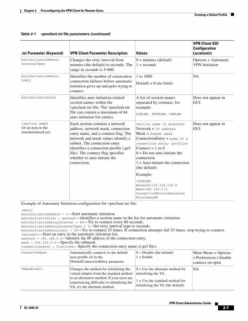
Chapter 2 Preconfiguring the VPN Client for Remote UsersCreating a Global Profile
AutoInitiationRetry-IntervalType
Changes the retry interval from minutes (the default) to seconds. The range in seconds is 5-600.
0 = minutes (default)1 = seconds
Options > Automatic VPN Initiation
AutoInitiationRetry-Limit
Identifies the number of consecutive connection failures before automatic initiation gives up and quits trying to connect.
1 to 1000
Default = 0 (no limit)
NA
AutoInitiationList Identifies auto initiation-related section names within the vpnclient.ini file. The vpnclient.ini file can contain a maximum of 64 auto initiation list entries.
A list of section names separated by commas; for example:
SJWLAN, RTPWLAN, CHWLAN
Does not appear in GUI
[section name]
(of an item in the AutoInitiationList)
Each section contains a network address, network mask, connection entry name, and a connect flag. The network and mask values identify a subnet. The connection entry identifies a connection profile (.pcf file). The connect flag specifies whether to auto initiate the connection.
Section name in brackets
Network = IP addressMask = Subnet maskConnectionEntry = name of a connection entry (profile)
Connect = 1 or 00 = Do not auto initiate the connection1 = Auto initiate the connection (the default)
Example:
[SJWLAN]Network=110.110.110.0Mask=255.255.0.0ConnectionEntry=SantaJuanWirelessLAN
Does not appear in GUI
Example of Automatic Initiation configuration for vpnclient.ini file:
[main]AutoInitiationEnable = 1—Start automatic initiation.autoInitiationList = autonet—identifies a section name in the list for automatic initiation.AutoInitiationRetryInterval = 60—Try to connect every 60 seconds.AutoInitiationRetryIntervalType = 1—Set retry interval type to seconds.AutoInitiationRetryLimit = 25—Try to connect 25 times. If connection attempts fail 25 times, stop trying to connect.[autonet]—Start an entry in the automatic initiation list.network = 192.168.0.0—Identify the IP address of the connection entry.mask = 255.255.0.0—Specify the submaskconnectionentry = flatirons—Specify the connection entry name s(.pcf file).
ConnectOnOpen Automatically connects to the default user profile set in the DefaultConnectionEntry parameter
0 = Disable (the default)1 = Enable
Main Menu > Options > Preferences > Enable connect on open
VAEnableAlt Changes the method for initializing the virtual adapter from the standard method to an alternative method. If your users are experiencing difficulty in initializing the VA, try the alternate method.
0 = Use the alternate method for initializing the VA
1 = Use the standard method for initializing the VA (the default)
NA
Table 2-1 vpnclient.ini file parameters (continued)
.ini Parameter (Keyword) VPN Client Parameter Description Values
VPN Client GUI Configuration Location(s)
2-7VPN Client Administrator Guide
OL-5492-01

Chapter 2 Preconfiguring the VPN Client for Remote UsersCreating a Global Profile
AddDhcpRoute (Windows only)
Adds a route that bypasses all traffic going to the DHCP server. This is the normal behavior. However, if your users do not want the VPN Client to bypass all traffic going to the DHCP server because other services exist on the server, use this parameter to change the default behavior of the software.
0 = Do not add a route to bypass the DHCP server1 = Add a route to bypass the DHCP server (default)
For each class that follows, use the LogLevel= parameter to set the logging level
[LOG.IKE] Identifies the Internet Key Exchange class for setting the logging level.
[LOG.IKE]
Enter exactly as shown.
Log > Settings
[LOG.CM] Identifies the Connection Manager class for setting the logging level.
[LOG.CM]
Enter exactly as shown.
Log > Settings
[LOG.XAUTH] Identifies the Extend authorization class for setting the logging level.
[LOG.XAUTH]
Enter exactly as shown.
Log > Settings
[LOG.PPP](Windows-only)
Identifies the PPP class for setting the logging level.
[LOG.PPP]
Enter exactly as shown.
Log > Settings
[LOG.CVPND] Identifies the Cisco VPN Daemon class for setting the logging level.
[LOG.CVPND]
Enter exactly as shown.
Log > Settings
[LOG.CERT] Identifies the Certificate Management class for setting the logging level.
[LOG.CERT]
Enter exactly as shown.
Log > Settings
[LOG.IPSEC] Identifies the IPSec module class for setting the logging level.
[LOG.IPSEC]
Enter exactly as shown.
Log > Settings
[LOG.FIREWALL](Windows-only)
Identifies the FWAPI class for setting the logging level.
[LOG.FIREWALL]
Enter exactly as shown
Log > Settings
[LOG.CLI] Identifies the Command-Line Interface class for setting the logging level.
[LOG.CLI]
Enter exactly as shown
Log > Settings
[LOG.GUI] Identifies the Graphical User Interface class for setting the logging level.
[LOG.GUI]
Enter exactly as shown
Log > Settings
LogLevel= Determines the log level for individual classes that use logging services. By default, the log level for all classes is Low. You can use this parameter to override the default setting for the preceding [LOG] parameters.
The VPN Client supports log levels from 1 (lowest) to 15 (highest).
Default = 1
To set logging levels, you must first enable logging: EnableLog=1.
Log > Settings
Table 2-1 vpnclient.ini file parameters (continued)
.ini Parameter (Keyword) VPN Client Parameter Description Values
VPN Client GUI Configuration Location(s)
2-8VPN Client Administrator Guide
OL-5492-01

Chapter 2 Preconfiguring the VPN Client for Remote UsersCreating a Global Profile
[CertEnrollment] Required keyword to identify the Certificate Enrollment section.
[CertEnrollment]
Enter exactly as shown.
Does not appear in GUI
SubjectName= Identifies the username associated with this certificate.
Maximum of 519 alphanumeric characters.
Certificates > Enroll Certificate Enrollment form
Company= Identifies the company or organization of the certificate owner.
Maximum of 129 alphanumeric characters.
Certificates > Enroll Certificate Enrollment form
Department= Identifies the department or organizational unit of the certificate owner. If matching by IPSec group in a VPN 3000 Concentrator, must match the group name in the configuration.
Maximum of 129 alphanumeric characters.
Certificates > Enroll Certificate Enrollment form
State= Identifies the state or province of the certificate owner.
Maximum of 129 alphanumeric characters.
Certificates > Enroll Certificate Enrollment form
Country= Identifies the two-letter code identifying the country of this certificate owner.
Maximum of 2 alphanumeric characters.
Certificates > Enroll Certificate Enrollment form
Email= Identifies the certificate owner’s email address.
Maximum of 129 alphanumeric characters.
Certificates > Enroll Certificate Enrollment form
IPAddress Identifies the IP address of the system of the certificate owner.
Internet address in dotted decimal notation.
Certificates > Enroll Certificate Enrollment form
Domain Identifies the fully qualified domain name of the host that is serving the certificate owner.
Maximum of 129 alphanumeric characters.
Certificates > Enroll Certificate Enrollment form
CADomainName= Identifies the domain name that the certificate authority belongs to; for network enrollment.
Maximum of 129 alphanumeric characters.
Certificates > Enroll Certificate Enrollment form
CAHostAddress= Identifies the IP address or hostname of the certificate authority.
Internet hostname or IP address in dotted decimal notation. Maximum of 129 alphanumeric characters.
Certificates > Enroll Certificate Enrollment form
CACertificate= Identifies the name of the self-signed certificate issued by the certificate authority.
Maximum of 519 alphanumeric characters.
Note: The VPNClient GUI ignores a read-only setting on this parameter.
Certificates > Enroll Certificate Enrollment form
Table 2-1 vpnclient.ini file parameters (continued)
.ini Parameter (Keyword) VPN Client Parameter Description Values
VPN Client GUI Configuration Location(s)
2-9VPN Client Administrator Guide
OL-5492-01

Chapter 2 Preconfiguring the VPN Client for Remote UsersCreating a Global Profile
NetworkProxy=(Windows-only)
Identifies a proxy server you can use to route HTTP traffic. Using a network proxy can help prevent intrusions into your private network.
IP address in dotted decimal notation or domain name. Maximum of 519 alphanumeric characters. The proxy setting sometimes has a port associated with it.
Example:10.10.10.10:8080
Does not appear in GUI
[ApplicationLauncher](Windows-only)
(No VPN Client field)
Required keyword to identify Application Launcher section.
[ApplicationLauncher]
Enter exactly as shown, as first entry in the section.
Does not appear in GUI
Enable=(Windows-only)
Use this parameter to allow VPN Client users to launch an application when connecting to the private network.
0 = Disabled (default)1 = Enabled
Disabled means no launching.
Options> Application Launcher
Command=(Windows-only)
The name of the application to be launched. This variable includes the pathname to the command, and the name of the command complete with arguments.
command string
Maximum 512 alphanumeric characters.
Example:
c:\auth\swtoken.exe.
Options> Application Launcher> Application
[DNS](Windows-only)
(No VPN Client field)
Required keyword to identify DNS section.
[DNS]
Enter exactly as shown, as first entry in the section.
Does not appear in GUI.
AppendOriginalSuffix=(Windows-only)
Determines the way the VPN Client treats suffixes to domain names. See “DNS Suffixes and the VPN Client—Windows 2000 and Windows XP Only”, following this table.
0 = do nothing1= append the primary DNS suffix to the suffix that the VPN Concentrator supplies. This is the default value.2= append the primary and connection-specific DNS suffixes to the suffix that the VPN Concentrator supplies.
Does not appear in GUI.
[RadiusSDI] Required keyword to identify the RADIUS SDI extended authentication (XAuth) section. Configure this section to enable a VPN Client to handle Radius SDI authentication the same as native SDI authentication, which makes authentication easier for VPN Client users to authenticate using SDI.
Enter exactly as shown. Does not appear in GUI.
Table 2-1 vpnclient.ini file parameters (continued)
.ini Parameter (Keyword) VPN Client Parameter Description Values
VPN Client GUI Configuration Location(s)
2-10VPN Client Administrator Guide
OL-5492-01

Chapter 2 Preconfiguring the VPN Client for Remote UsersCreating a Global Profile
QuestionSubStr Uniquely identifies question-type RADIUS SDI Xauth prompts.
Enter text up to 32 bytes in length. The default text is a question mark.
Example:
“Are you prepared to have the system generate your PIN? (y/n):”
Response: ____________
The question appears in the GUI during extended authentication. It is followed by a Response field.
NewPinSubStr Uniquely identifies new PIN RADIUS SDI Xauth prompts.
Enter text up to 32 bytes in length. Default text is “new PIN.”
Example:
“Enter a new PIN of 4 to 8 digits.”
Appears in the GUI during extended authentication.
NewPasscodeSubStr Uniquely identifies new passcode RADIUS Xauth prompts.
Enter text up to 32 bytes in length. Default text is “new passcode.”
Example:
“PIN accepted.
Wait for the token code to change, then enter the new passcode”
Appears in the GUI during extended authentication.
[Netlogin](windows-only
Identifies the Force Network Login section of the vpnclient.ini file. This feature forces a user on Windows NT, Windows 2000, and Windows XP to log out and log back in to the network without using cached credentials.
Enter exactly as shown; this is required as part of the feature.
Does not appear in the GUI.
Note You cannot use this feature with Start Before Logon. If users are connecting via dialup (RAS), you should add the registry key described in the Microsoft article: http://support.microsoft.com/default.aspx?scid=kb;en-us;Q158909. Adding the registry key assures that the RAS connection does not drop when the user gets logged off.
Force(windows-only)
Specifies what action to take for the Force Network Login feature. This parameter is required for this feature.
0 = (default) Do not force the user to log out and log in.1 = Force user to log out when the Wait time is reached unless an option is selected.2 = Disconnect VPN session upon reaching the Wait time unless an option is selected.3 = Wait for the user to select Connect or Disconnect.
Does not appear in the GUI.
Table 2-1 vpnclient.ini file parameters (continued)
.ini Parameter (Keyword) VPN Client Parameter Description Values
VPN Client GUI Configuration Location(s)
2-11VPN Client Administrator Guide
OL-5492-01

Chapter 2 Preconfiguring the VPN Client for Remote UsersCreating a Global Profile
Wait(windows-only)
Determines the number of seconds to wait before performing an action specified by the Force parameter. This parameter is optional.
x number of seconds.
The default is 5 seconds.
Does not appear in the GUI.
DefaultMsg(windows-only)
Specifies a message to display before performing the action specified by the Force parameter. Message can vary according to setting of Force. This parameter is optional.
Ascii text up to 1023 bytes.
Default message = You will soon be disconnected.
Does not appear in the GUI.
Separator(windows-only)
Specifies the separator text that separates banner text from the message. If no banner exists, the separator is not displayed. This parameter is optional.
Ascii text up to 511 bytes.
Default separator = ------------
Does not appear in the GUI.
[GUI] Required keyword to identify the section of the file that lets you control features of the Graphical User Interface application.
[GUI]
Enter exactly as shown, as first entry in the section.
Does not appear in the GUI.
DefaultConnectionEntry Specifies the name of the connection entry for the VPN Client to use to initiate a connection, unless otherwise indicated.
ConnectionEntryName Connection Entries > Add/Modify > Set as default entry.
WindowWidth Controls the width of the window. Default = 578 pixels Manual control
WindowHeight Controls the height of the window. Default = 367 pixels Manual control
WindowX Controls the X coordinate of the window.
0 to 1024 pixels
Default = 324
Where the window appears horizontally relative to your monitor’s screen
WindowY Controls the Y coordinate of the window.
0 to 768 pixels
Default = 112
Where the window appears vertically relative to your monitor’s screen
VisibleTab Tracks which tab is currently visible in the advanced mode main dialog; an index.
Connection EntriesCertificatesLog
VPN Client main dialog
ConnectionAttibute Indicates the current setting for the status bar display. The status bar is the line area at the bottom of the dialog that shows the state of the connection (connect/not connected), if connected, the name of the connection entry on the left and what the status is on the right.
If you click on the arrow on the right end of the status bar, the right part of the status bar changes. This value records the current display selection.
VPN Client main dialog > status bar
Table 2-1 vpnclient.ini file parameters (continued)
.ini Parameter (Keyword) VPN Client Parameter Description Values
VPN Client GUI Configuration Location(s)
2-12VPN Client Administrator Guide
OL-5492-01

Chapter 2 Preconfiguring the VPN Client for Remote UsersCreating a Global Profile
Creating and Using a Default User ProfileYou can configure a default user profile, which is the same as the default connection entry capability in the VPN Client GUI (see VPN Client User Guide for Windows, Chapter 4, “Setting a Default Connection Entry” or VPN Client User Guide for Mac OS X, Chapter 5, “Connecting to a Default Connection Entry.” The parameter DefaultConnectionEntry in the VPN Client .ini file contains the name of the default user profile. Then you can use the Connect on Open feature to configure the VPN Client to connect to the default user profile when it connects to a secure gateway. To activate this configuration, using the parameters in the vpnclient.ini file, use the following procedure:
Step 1 Specify the name of a default connection entry in the DefaultConnectionEntry parameter; for example, DefaultConnectionEntry=myprofile.
Step 2 Enable the ConnectOnOpen parameter (ConnectOnOpen=1).
DNS Suffixes and the VPN Client—Windows 2000 and Windows XP OnlyWhen a command or program such as ping server123 passes a hostname without a suffix to a Windows 2000 or Windows XP platform, Windows 2000/XP has to convert the name into a fully-qualified domain name (FQDN). The Windows operating system has two methods for adding suffixes to domain names: Method 1 and Method 2. This section describes these two methods.
AdvancedView Toggles between Advanced and Simple modes of operation.
Simple Mode = 0Advanced Mode = 1 (default)
Main menu > Options menu > Advanced/ Simple Mode
MinimizeOnConnect Controls whether to minimize to a system tray icon upon connection to a VPN central-site device.
0 = Do not minimize1 = Do minimize (default)
Main menu > Options > Preferences > Hide upon connect
UseWindowSettings Controls whether to save windows settings.
0 = No1 = Yes (default)
Main menu > Options > Preferences > Save window settings
ShowTooltips Controls whether to display the tool tips.
0 = No1 = Yes (default)
Main menu > Options > Preferences > Enable tooltips
ShowConnectHistory Controls whether to display the connection history dialog during connection negotiation.
0 = No (default)1 = Yes
Main menu > Options > Preferences > Enable Connection History Display
AccessibilityOption Controls whether to activate 508 accessibility options (Windows only)
0 = No (default)1 = Yes
Main menu > Options > Preferences > Enable accessibility options
Table 2-1 vpnclient.ini file parameters (continued)
.ini Parameter (Keyword) VPN Client Parameter Description Values
VPN Client GUI Configuration Location(s)
2-13VPN Client Administrator Guide
OL-5492-01

Chapter 2 Preconfiguring the VPN Client for Remote UsersCreating a Global Profile
Method 1—Primary and Connection-Specific DNS Suffixes
A primary DNS suffix is global across all adapters. A connection-specific DNS suffix is only for a specific connection (adapter), so that each connection can have a different DNS suffix.
Identifying a Primary DNS Suffix
A primary suffix comes from the computer name. To find or assign a primary DNS suffix, use the following procedure according to your operating system:
On Windows 2000
Step 1 On a Windows 2000 desktop, right click the My Computer icon, and select Properties from the menu.
The System Properties dialog displays.
Step 2 Open the Network Identification tab.
The entry next to Full Computer Name identifies the computer’s name and DNS suffix on this screen, for example, SILVER-W2KP.tango.dance.com. The part after the first dot is the primary DNS suffix, in this example: tango.dance.com.
Step 3 To change the primary DNS suffix, click Properties on the Network Identification tab.
The Identification Changes dialog displays.
Step 4 Click More....
This action displays the DNS Suffix and Net BIOS Computer Name dialog. The Primary DNS suffix of this computer entry identifies the primary suffix. You can edit this entry.
On Windows XP
Step 1 Right click My Computer, and select Properties from the menu.
The System Properties dialog displays.
Step 2 Open the Computer Name tab.
The entry next to Full Computer Name identifies the computer’s name and DNS suffix on this screen (for example, SILVER-W2KP.tango.dance.com). The part after the first dot is the primary DNS suffix (in this example: tango.dance.com).
Step 3 To change the primary DNS suffix, click Change on the Computer Name tab.
The Computer Name Changes dialog displays.
Step 4 Click More....
This action displays the DNS Suffix and Net BIOS Computer Name dialog. The Primary DNS suffix of this computer entry identifies the primary suffix. You can edit this entry.
Identifying a Connection-Specific DNS Suffix
You can identify a connection-specific DNS suffix in one of two ways.
1. The connection-specific DNS value is listed as the DNS suffix for the selected connection on the Advanced TCP/IP Settings dialog.
2-14VPN Client Administrator Guide
OL-5492-01

Chapter 2 Preconfiguring the VPN Client for Remote UsersCreating a Global Profile
Note The following instructions are for a Windows 2000 platform. There may be slight variations on a Windows XP platform.
To display the Advanced TCP/IP Settings dialog, use the following procedure:
Step 1 Right click the My Network Places icon to display the Properties dialog, which lists your connections.
Step 2 Double-click on a connection (for example, local) to display its Properties dialog. The connection uses the checked components, such as those shown in Figure 2-1, which shows components of a connection named Local Area Connection.
Figure 2-1 Displaying Properties for a Connection
Step 3 Double-click Internet Protocol (TCP/IP) to reveal its properties.
Step 4 Select Advanced.
Step 5 Display the DNS tab and look at DNS suffix for this connection box. If the box is empty, you can have it assigned by the DHCP Server.
a. To identify the connection-specific suffix assigned by the DHCP Server, use the ipconfig /all command (Alternative 2, below) and for the DNS Server address.
2. The connection-specific DNS value is listed in the output from the ipconfig /all command, executed at the command-line prompt. Look under Windows 2000 IP Configuration for DNS Suffix Search List. Under Ethernet Adapter Connection Name, look for Connection-specific DNS Suffix.
2-15VPN Client Administrator Guide
OL-5492-01

Chapter 2 Preconfiguring the VPN Client for Remote UsersCreating a Global Profile
Method 2—User Supplied DNS Suffix
For this method, you can provide specific suffixes. You can view and change suffixes in the DNS tab of the connection properties page. The Append these DNS suffixes (in order) edit box supplies the name that you can edit. The values you provide here are global to all adapters.
VPN Client Behavior
When the VPN Client establishes a VPN tunnel to the VPN central device (for example, the VPN 3000 Concentrator), the VPN Client uses Method 2 without regard for the method that the Windows platform uses. If the Windows platform is using Method 2, the VPN Client appends the suffix provided by the VPN central device. This is the default behavior and works correctly with no problem.
However if Windows is using Method 1, the VPN Client does not append the primary or connection-specific suffix. To fix this problem, you can set the AppendOriginalSuffix option in the vpnclient.ini file. In Table 2-1, the [DNS] section contains this option:
[DNS]
AppendOriginalSuffix=1:
In this case, the VPN Client appends the primary DNS suffix to the suffix provided by the VPN Concentrator. While the tunnel is established, Windows has two suffixes: one provided by the VPN Concentrator and the primary DNS suffix.
AppendOriginalSuffix=2:
In this case, the VPN Client appends the primary and connection-specific DNS suffixes to the suffix provided by the VPN Concentrator. While the tunnel is established, Windows has three suffixes: one provided by the VPN Concentrator, the primary DNS suffix, and the connection-specific DNS suffix.
Note If Windows is using Method 2, adding these values to the vpnclient.ini file has no effect.
The VPN Client sets these values every time a tunnel is established and then restores the original configuration when tearing down the tunnel.
Setting Up RADIUS SDI Extended AuthenticationYou can configure the VPN Client to handle RADIUS SDI authentication the same way it handles “native” SDI authentication, which is more seamless and easier to use. With this configuration, users do not have to deal with the RSA SecurID software interface; the VPN Client software directly interfaces with the RSA SecureID software for the user.
To enable intelligent handling of RADIUS SDI authentication, you must configure one profile (.pcf) parameter and possibly three global (vpnclient.ini) parameters:
• In the vpnclient.ini file, enter the following information. (For complete information on these parameters, see Table 2-1.)
– RadiusSDI—identifies the configuration section for RADIUS SDI
– A question sub-string to identify question prompts (e.g. “?”)
– A new PIN sub-string to identify prompts for a new PIN
– A new passcode sub-string to identify prompts for a new passcode
2-16VPN Client Administrator Guide
OL-5492-01

Chapter 2 Preconfiguring the VPN Client for Remote UsersCreating Connection Profiles
• In the profile (connection entry) file under the Main section, enter the parameter “RadiusSDI = 1”. (See Table 2-2.)
Now when the request comes in to the VPN Client, the software identifies it as a RADIUS SDI extended authentication request and knows how to process the request.
Creating Connection ProfilesThe VPN Client uses parameters that must be uniquely configured for each remote user of the private network. Together these parameters make up a user profile, which is contained in a profile configuration file (.pcf file) in the VPN Client user’s local file system in the following directories:
• For Windows platforms—Program Files\Cisco Systems\VPN Client\Profiles (if the software installed in the default location)
• For the Linux, Solaris, and Mac OS X platforms— /etc/CiscoSystemsVPNClient/Profiles/
These parameters include the authentication type used, remote server address, IPSec group name and password, use of a log file, use of backup servers, and automatic Internet connection via Dial-Up Networking among many other features and requirements. Each connection entry has its own .pcf file. For example, if you have three connection entries, named Doc Server, Documentation, and Engineering, the Profiles directory shows the list of .pcf files.
Figure 2-2 shows the directory structure for the user profile in the Windows platforms.
Figure 2-2 List of .pcf files
Features Controlled by Connection ProfilesA connection profile (.pcf file) controls the following features on all platforms):
• Description of the connection profile
• The remote server address
• Authentication type
• Name of IPSec group containing the remote user
• Group password
• Connecting to the Internet via dial-up networking
2-17VPN Client Administrator Guide
OL-5492-01

Chapter 2 Preconfiguring the VPN Client for Remote UsersCreating Connection Profiles
• Name of remote user
• Remote user’s password
• Backup servers
• Split DNS
• Type of dial-up networking connection
• Transparent tunneling
• TCP tunneling port
• Allowing of local LAN access
• Enabling of IKE and ESP keepalives
• Setting of peer response time-out
• Certificate parameters for a certificate connection
• Setting of certificate chain
• Diffie-Hellman group
• Verification of the DN of a peer certificate
• RADIUS SDI extended authentication setting
• Use of SDI hardware token setting
• Split DNS setting
• Use legacy IKE port setting
A connection profile (.pcf file) controls the following additional features on the Windows platform:
• Dial-Up networking phone book entry for Microsoft
• Command string for connecting through an ISP
• NT domain
• Logging on to Microsoft Network and credentials
• Change the default IKE port from 500/4500 (must be explicitly added)
• Enable Force Network Login, which forces a user on Windows NT, Windows 2000, and Windows XP to log out and then log back in to the network without using cached credentials
• Enable/disable the browser proxy setting on the VPN Client for all connection types
Sample .pcf file
Note Connection profiles for the VPN Client are interchangeable between platforms. Keywords that are specific to the Windows platform are ignored by other platforms.
When you open the Doc Server.pcf file, it looks like the example below. This is a connection entry that uses preshared keys. Note that the enc_ prefix (for example, enc_GroupPwd) indicates that the value for that parameter is encrypted.
[main]Description=connection to TechPubs serverHost=10.10.99.30AuthType=1GroupName=docusers
2-18VPN Client Administrator Guide
OL-5492-01

Chapter 2 Preconfiguring the VPN Client for Remote UsersCreating Connection Profiles
GroupPwd=enc_GroupPwd=158E47893BDCD398BF863675204775622C494B39523E5CB65434D3C851ECF2DCC8BD488857EFAFDE1397A95E01910CABECCE4E040B7A77BFEnableISPConnect=0ISPConnectType=0ISPConnect=ISPCommand=Username=aliceSaveUserPassword=0UserPassword=enc_UserPassword=NTDomain=EnableBackup=1BackupServer=Engineering1, Engineering2, Engineering 3, Engineering4EnableMSLogon=0MSLogonType=0EnableNat=1EnableLocalLAN=0TunnelingMode=0TCPTunnelingPort=10000CertStore=0CertName=CertPath=CertSubjectNameSendCertChain=0VerifyCertDN=CN=”ID Cert”,OU*”Cisco”,ISSUER-CN!=”Entrust”,ISSURE-OU!*”wonderland”DHGroup=2PeerTimeOut=90ForceNetLogin=1
You can configure the VPN Client for remote users by creating a profile configuration file for each connection entry and distribute the .pcf files with the VPN Client software. These configuration files can include all, or only some, of the parameter settings. Users must configure those settings not already configured.
You can also distribute the VPN Client to users without a configuration file and let them configure it on their own. In this case, when they complete their configuration using the VPN Client program, they are in effect creating a .pcf file for each connection entry, which they can edit and share.
To protect system security you should not include key security parameters such as the IPSec group password, authentication username, or authentication password in .pcf files for remote users.
Note Whatever preconfiguring you provide, you must supply users with the information they need to configure the VPN Client. See “Gathering Information You Need” in Chapter 2 of the VPN Client User Guide for your platform.
Creating a .pcf file for a Connection ProfileEach user requires a unique configuration file. Use Notepad or another ASCII text editor to create and edit each file. Save as a text-only file with no formatting.
Naming the Connection Profile
For a Windows platform, you can create profile names that contain spaces. However, if you want to distribute profiles to other platforms (Linux, Mac OS X, or Solaris), the name cannot contain spaces.
2-19VPN Client Administrator Guide
OL-5492-01

Chapter 2 Preconfiguring the VPN Client for Remote UsersCreating Connection Profiles
Connection Profile Configuration Parameters
Table 2-2 lists all parameters, keywords, and values. It also includes the VPN Client parameter name (if it exists) that corresponds to the keyword and where it is configured on the VPN Client GUI.
You can configure each parameter on all VPN Client platforms unless specified.
Table 2-2 .pcf file parameters
.pcf Parameter (Keyword) VPN Client Parameter Description Values
VPN Client Configuration Location(s)
[main] (No VPN Client field)
Required keyword to identify main section.
[main]
As the first entry in the file, enter exactly as shown.
Does not appear in GUI
Description= Description
A line of text that describes this connection entry. Optional.
Any text.
Maximum 246 alphanumeric characters.
Connection Entry>New/Modify
Host= Remote server address
The hostname or IP address of the Cisco remote access server (a VPN central-site device) to which remote users connect.
Internet hostname, or IP address in dotted decimal notation.
Maximum 255 alphanumeric characters.
Connection Entry >New/Modify
AuthType= Authentication type
For a description of authentication and authentication types, see the VPN Client user guides for the platform you are using.
The authentication type of this user:
1 = Pre-shared keys (default)3 = Digital Certificate using an RSA signature.5 = Mutual authentication (see note below)
Connection Entry >New/Modify > Authentication
Note Setting up mutual or hybrid authentication for users:To use this authentication method, the VPN central-site device must have an identity certificate installed derived from a root certificate that matches the root certificate installed on the VPN Client system (the credentials used by both sides must match for mutual trust to take place). For information on how to provide a root certificate to a remote user during installation, consult the installation section in the user guide for the platform you are using. For VPN Concentrator configuration information see Configuring Mutual Authentication.
GroupName= Group Name
The name of the IPSec group that contains this user. Used with pre-shared keys.
The exact name of the IPSec group configured on the VPN central-site device.
Maximum 32 alphanumeric characters. Case-sensitive.
Connection Entry >New/Modify > Authentication
GroupPwd= Group Password
The password for the IPSec group that contains this user. Used with pre-shared keys.
The first time the VPN Client reads this password, it replaces it with an encypted one (enc_GroupPwd).
The exact password for the IPSec group configured on the VPN central-site device.
Minimum of 4, maximum 32 alphanumeric characters. Case-sensitive clear text.
Connection Entry >New/Modify > Authentication
2-20VPN Client Administrator Guide
OL-5492-01

Chapter 2 Preconfiguring the VPN Client for Remote UsersCreating Connection Profiles
encGroupPwd= The password for the IPSec group that contains the user. Used with preshared keys. This is the scrambled version of the GroupPwd.
Binary data represented as alphanumeric text.
Does not appear in GUI.
EnableISPConnect=(Windows-only)
Connect to the Internet via Dial-Up Networking
Specifies whether the VPN Client automatically connects to an ISP before initiating the IPSec connection; determines whether to use PppType parameter.
0 = Disable (default)1 = Enable
The VPN Client GUI ignores a read-only setting on this parameter.
Connection Entry >New/Modify >Dial-Up > Connect to the Internet via dial-up
ISPConnectType=(Windows-only)
Dial-Up Networking connection entry type
Identifies the type to use: ISPConnect or ISPCommand.
0 = ISPConnect (default)1 = ISPCommand
The VPN Client GUI ignores a read-only setting on this parameter.
Connection Entry >New/Modify >Dial-Up > (choosing either DUN or Third Party (command)
ISPConnect=(Windows-only)
Dial-Up Networking Phonebook Entry (Microsoft)
Use this parameter to dial into the Microsoft network; dials the specified dial-up networking phone book entry for the user’s connection.
Applies only if EnableISPconnect=1 and ISPConnectType=0.
phonebook_name
This variable is the name of the phone book entry for DUN – maximum of 256 alphanumeric characters.
The VPN Client GUI ignores a read-only setting on this parameter.
Connection Entry >New/Modify >Dial-Up > Microsoft Dial-Up Networking > Phonebook
ISPCommand=(Windows-only)
Dial-Up Networking Phonebook Entry (command)
Use this parameter to specify a command to dial the user’s ISP dialer.
Applies only if EnableISPconnect=1 and ISPConnectType=1.
command string
This variable includes the pathname to the command and the name of the command complete with arguments; for example:
c:\isp\ispdialer.exe dialEngineering
Maximum 512 alphanumeric characters.
Connection Entry >New/Modify >Dial-Up > Third party dialup program > Application
Username= User Authentication: Username
The name that authenticates a user as a valid member of the IPSec group specified in GroupName.
The exact username. Case-sensitive, clear text, maximum of 32 characters.
The VPN Client prompts the user for this value during user authentication.
Connection Entry >New/Modify > Authentication
Table 2-2 .pcf file parameters (continued)
.pcf Parameter (Keyword) VPN Client Parameter Description Values
VPN Client Configuration Location(s)
2-21VPN Client Administrator Guide
OL-5492-01

Chapter 2 Preconfiguring the VPN Client for Remote UsersCreating Connection Profiles
UserPassword= User Authentication: Password
The password used during extended authentication.
The first time the VPN Client reads this password, it saves it in the file as the enc_UserPassword and deletes the clear-text version. If SaveUserPassword is disabled, then the VPN Client deletes the UserPassword and does not create an encrypted version.
You should only modify this parameter manually if there is no GUI interface to manage profiles.
Maximum of 32 alphanumeric characters, case sensitive.
Connection Entry >New/Modify > Authentication
encUserPassword Scrambled version of the user’s password
Binary data represented as alphanumeric text.
Does not appear in GUI.
SaveUserPassword Determines whether or not the user password or its encrypted version are valid in the profile.
This value is pushed down from the VPN central-site device.
0 = (default) do not allow user to save password information locally.1 = allow user to save password locally.
Does not appear in GUI.
NTDomain=(Windows-only)
User Authentication: Domain
The NT Domain name configured for the user’s IPSec group. Applies only to user authentication via a Windows NT Domain server.
NT Domain name. Maximum 14 alphanumeric characters. Underbars are not allowed.
Connection Entry >New/Modify
EnableBackup= Enable backup server(s)
Specifies whether to use backup servers if the primary server is not available.
0 = Disable (default)1 = Enable
Connection Entry > New/Modify > Backup Servers
BackupServer= (Backup server list)
List of hostnames or IP addresses of backup servers.
Applies only if EnableBackup=1.
Legitimate Internet hostnames, or IP addresses in dotted decimal notation. Separate multiple entries by commas. Maximum of 255 characters in length.
Connection Entry > New/Modify > Backup Servers
EnableMSLogon=(Windows-only)
Logon to Microsoft Network.
Specifies that users log on to a Microsoft network.
Applies only to systems running Windows 9x.
0 = Disable1 = Enable (Default)
Connection Entry > New/Modify > Microsoft Logon
This is available only on Windows 98 and Windows ME.
Table 2-2 .pcf file parameters (continued)
.pcf Parameter (Keyword) VPN Client Parameter Description Values
VPN Client Configuration Location(s)
2-22VPN Client Administrator Guide
OL-5492-01

Chapter 2 Preconfiguring the VPN Client for Remote UsersCreating Connection Profiles
MSLogonType=(Windows-only)
Use default system logon credentials.
Prompt for network logon credentials.
Specifies whether the Microsoft network accepts the user’s Windows username and password for logon, or whether the Microsoft network prompts for a username and password.
Applies only if EnableMSLogon=1.
0 = (default) Use default system logon credentials; i.e., use the Windows logon username and password.1 = Prompt for network logon username and password.
Connection Entry > New/Modify > Microsoft Logon
This is available only on Windows 98 and Windows ME.
EnableNat= Enable Transparent Tunneling.
Allows secure transmission between the VPN Client and a secure gateway through a router serving as a firewall, which may also be performing NAT or PAT.
0 = Disable1 = Enable (default)
Connection Entry > New/Modify > Transport
TunnelingMode= Specifies the mode of transparent tunneling, over UDP or over TCP; must match that used by the secure gateway with which you are connecting.
0 = UDP (default)1 = TCP
Connection Entry > New/Modify > Transport
TCPTunnelingPort= Specifies the TCP port number, which must match the port number configured on the secure gateway.
Port number from 1 through 65545
Default = 10000
Connection Entry> New/Modify > Transport
EnableLocalLAN= Allow Local LAN Access.
Specifies whether to enable access to resources on a local LAN at the Client site while connected through a secure gateway to a VPN device at a central site.
0 = Disable (default)1 = Enable
Connection Entry > New/Modify > Transport
PeerTimeout= Peer response time-out
The number of seconds to wait before terminating a connection because the VPN central-site device on the other end of the tunnel is not responding.
Number of seconds
Minimum = 30 secondsMaximum = 480 secondsDefault = 90 seconds
Connection Entry > New/Modify > Transport
Table 2-2 .pcf file parameters (continued)
.pcf Parameter (Keyword) VPN Client Parameter Description Values
VPN Client Configuration Location(s)
2-23VPN Client Administrator Guide
OL-5492-01

Chapter 2 Preconfiguring the VPN Client for Remote UsersCreating Connection Profiles
CertStore= Certificate Store
Identifies the type of store containing the configured certificate.
0 = No certificate (default)1 = Cisco2 = MicrosoftThe VPN Client GUI ignores a read-only (!) setting on this parameter. (See note)
Windows GUI
Does not appear in GUI. You can view on Certificates tab.
Mac OS X GUI
Connection Entry > New/Modify > Transport
Note Normally, if a parameter is marked as read only, the GUI disables the checkbox or edit box so users can not change the value of the parameter. However, this is not true for Certificate parameters. These values cannot be overwritten in the file. Users can change them in the GUI display, but these changes are not saved.
CertName= Certificate Name
Identifies the certificate used to connect to a VPN central-site device.
Maximum 129 alphanumeric characters
The VPN Client GUI ignores a read-only setting on this parameter.
Certificates > View
CertPath= The complete pathname of the directory containing the certificate file.
Maximum 259 alphanumeric characters
The VPN Client GUI ignores a read-only setting on this parameter.
Certificates > Import
CertSubjectName The fully qualified distinguished name (DN) of certificate’s owner. If present, the VPN Dialer enters the value for this parameter.
Either do not include this parameter or leave it blank.
The VPN Client GUI ignores a read-only setting on this parameter.
Certificates > View
CertSerialHash A hash of the certificate’s complete contents, which provides a means of validating the authenticity of the certificate. If present, the VPN Dialer enters the value for this parameter.
Either do not include this parameter or leave it blank.
The VPN Client GUI ignores a read-only setting on this parameter.
Certificates > View
Note When processing certificate authentication, the software uses the following fields in priority order:CertSerialHash CertSubjNameCertNameIf there are two ceertificates with the same DN or CN, the software chooses the first certificate.
SendCertChain Sends the chain of CA certificates between the root certificate and the identity certificate plus the identity certificate to the peer for validation of the identity certificate.
0 = disable (default)1 = enable
• Connection Entry > New/Modify
• Certificates > Export
Table 2-2 .pcf file parameters (continued)
.pcf Parameter (Keyword) VPN Client Parameter Description Values
VPN Client Configuration Location(s)
2-24VPN Client Administrator Guide
OL-5492-01

Chapter 2 Preconfiguring the VPN Client for Remote UsersCreating Connection Profiles
VerifyCertDN Prevents a user from connecting to a valid gateway by using a stolen but valid certificate and a hijacked IP address. If the attempt to verify the domain name of the peer certificate fails, the client connection also fails.
Include any certificate DN values of both subject and issuer:
You can use all valid ASCII characters including -_@<>()., as well as wildcards. See example:
Does not appear in GUI
Example: VerifyCertDN=CN=”ID Cert”,OU*”Cisco”,ISSUER-CN!=”Entrust”,ISSUER-OU!*”wonderland”CN=”ID Cert”—Specifies an exact match on the CN.OU*”Cisco”—Specifies any OU that contains the string “Cisco”.ISSUER-CN!”Entrust”—Specifies that the Issuer CN must not equal “Entrust”.ISSUER-OU!*”wonderland”—Specifies that the Issuer OU must not contain “wonderland”.
DHGroup Allows a network administrator to override the default group value on a VPN device used to generate Diffie- Hellman key pairs.
1 = modp group 12 = modp group 2 (default)5 = modp group 5
Note: This value is preset only for pre-shared keys; for a certificate-authenticated connection, the DHGroup number is negotiated.
Does not appear in GUI
RadiusSDI Tells the VPN Client to assume that Radius SDI is being used for extended authentication (XAuth).
0 = No (default)1 = Yes
If this parameter is enabled, the prompts in the GUI for SDI authentication are from Radius SDI and configured using parameters in the vpnclient.ini file.
SDIUseHardwareToken Enables a connection entry to avoid using RSA SoftID software.
0 = Yes, use RSA SoftID (default)1 = No, ignore RSA SoftID software installed on the PC.
Does not appear in GUI
EnableSplitDNS Determines whether the connection entry is using splitDNS, which can direct packets in clear text over the Internet to domains served through an external DNS or through an IPSec tunnel to domains served by a corporate DNS. This feature is configured on the VPN 3000 Concentrator and is used in a split-tunneling connection.
Note You must also enable this feature on the VPN central-site device you are connecting to.
0 = No1 = Yes (default)
Does not appear in GUI
Table 2-2 .pcf file parameters (continued)
.pcf Parameter (Keyword) VPN Client Parameter Description Values
VPN Client Configuration Location(s)
2-25VPN Client Administrator Guide
OL-5492-01

Chapter 2 Preconfiguring the VPN Client for Remote UsersCreating Connection Profiles
Distributing Configured VPN Client Software to Remote UsersWhen you have created the VPN Client profile configuration file, you can distribute it to users separately or as part of the VPN Client software.
Separate Distribution
To distribute the configuration file separately and have users import it to the VPN Client after they have installed it on their PCs, follow these steps:
Note For the Mac OS X platform, the configuration file is placed in the Profiles folder before the VPN Client is installed. See Chapter 2 of the VPN Client User Guide for Mac OS X for more information.
Step 1 Distribute the appropriate profile files to users on whatever media you prefer.
Step 2 Supply users with necessary configuration information.
UseLegacyIKEPort Changes the default IKE port from 500/4500 to dynamic ports to be used during all connections. You must explicitly enter this parameter into the .pcf file.
0 = Turn off the legacy setting; use dynamic ports with cTCP.
1 = (default) Maintain the legacy setting 500/4500. This lets TCP/UDP work easily with VPN central-site devices that support cTCP. This setting enables interoperability with VPN central-site devices that expect the VPN Client to use static port assignments. Enabling this parameter inhibits interoperability with certain versions of Windows.
Does not appear in GUI
ForceNetlogin (windows-only)
Enables the Force Net Login feature for this connection profile.
0 = Do not force the user to log out and log in (default).1 = Force user to log out when the Wait time is reached unless an option is selected.2 = Disconnect VPN session upon reaching the Wait time unless an option is selected.3 = Wait for the user to select Connect or Disconnect.
Does not appear in GUI
Table 2-2 .pcf file parameters (continued)
.pcf Parameter (Keyword) VPN Client Parameter Description Values
VPN Client Configuration Location(s)
2-26VPN Client Administrator Guide
OL-5492-01

Chapter 2 Preconfiguring the VPN Client for Remote UsersCreating Connection Profiles
Step 3 Instruct users to:
a. Install the VPN Client according to the instructions in the VPN Client User Guide for your platform.
b. Start the VPN Client and follow the instructions in Chapter 5 of the VPN Client User Guide for your platform. See the section “Importing a VPN Client Configuration File.” (Windows-only)
c. Finish configuring the VPN Client according to the instructions in Chapter 4of the VPN Client User Guide for your platform.
d. Connect to the private network, and enter parameters according to the instructions in Chapter 5 of the VPN Client User Guide for your platform.
Distribution with the VPN Client Software
If the vpnclient.ini file is bundled with the VPN Client software when it is first installed, it automatically configures the VPN Client during installation. You can also distribute the profile files (one .pcf file for each connection entry) as preconfigured connection profiles for automatic configuration.
To distribute preconfigured copies of the VPN Client software to users for installation, perform the following steps:
Step 1 Copy the VPN Client software files from the distribution CD-ROM into each directory where you created an vpnclient.ini (global) file and separate connection profiles for a set of users.
Note For the Mac OS X platform, preconfigured files are placed in the Profiles and Resources folders before the VPN Client is installed. The vpnclient.ini file is placed in the installer directory. See Chapter 2 of the VPN Client User Guide for Mac OS X for more information.
Step 2 Prepare and distribute the bundled software.
CD-ROM or network distribution: Be sure the vpnclient.ini file and profile files are in the same directory with all the CD-ROM image files. You can have users install from this directory through a network connection; or you can copy all files to a new CD-ROM for distribution; or you can create a self-extracting ZIP file that contains all the files from this directory, and have users download it, and then install the software.
Step 3 Supply users with any other necessary configuration information and instructions. See Chapter 2 of the VPN Client User Guide for your platform.
2-27VPN Client Administrator Guide
OL-5492-01

Chapter 2 Preconfiguring the VPN Client for Remote UsersCreating Connection Profiles
2-28VPN Client Administrator Guide
OL-5492-01

OL-5492-01
C H A P T E R 3
Updating VPN Client SoftwareThere are two ways to update VPN Client software. You can place a new release or update on a web server, called the update server, and notify remote users of all client types (Linux, Windows, Mac OS X and so on) where to retrieve and install the updated software. Or, starting with Release 4.6, you can automatically update VPN Client software for Windows 2000 and Windows XP remote users.
This section has the following sections:
Enabling Client Update (All Client Types)
Updating the VPN Client Software Automatically on Windows 2000 and Windows XP Systems
Managing Autoupdates
How Automatic Update Works
Enabling Client Update (All Client Types)To update VPN Client software, you must enable Client Update on the VPN Concentrator. When you enable Client Update, you notify VPN Client users that it is time to update the VPN Client software on their remote systems. The notification includes a location containing the update package (the update does not happen automatically).
Note Each update folder on the web server must contain only one version package from Cisco. If you need more than one version, configure more groups on the VPN Concentrator to update from different web server folders.
Use the Client Update procedure at the VPN 3000 Concentrator to configure a client notification:
Step 1 To enable Client Update, go to Configuration | System | Client Update and click Enable.
Step 2 At the Configuration | System | Client Update | Enable screen, check Enabled (the default) and then click Apply.
Step 3 On the Configuration | System | Client Update | screen, click Entries.
Step 4 On the Entries screen, click Add. The VPN Concentrator Manager, displays the Configuration | System | Client Update | Entries | Add or Modify screen.
3-1VPN Client Administrator Guide

Chapter 3 Updating VPN Client SoftwareUpdating the VPN Client Software Automatically on Windows 2000 and Windows XP Systems
Step 5 For Client Type, enter the operating systems to notify:
• Windows includes all Windows based platforms
• Win9X includes Windows 95, Windows 98, and Windows ME platforms
• WinNT includes Windows NT 4.0, Windows 2000, and Windows XP platforms
• Linux
• Solaris
• Mac OS X
Note The VPN 3000 Concentrator sends a separate notification message for each entry in a Client Update list. Therefore your client update entries must not overlap. For example, the value Windows includes all Windows platforms, and the value WinNT includes Windows NT 4.0, Windows 2000 and Windows XP platforms. So you would not include both Windows and WinNT. To find out the client types and version information, click on the lock icon at the top left corner of the Cisco Systems VPN Client main window and choose About VPN Client.
Step 6 In the URL field, enter the URL that contains the notification.
To activate the Launch button on the VPN Client Notification, the message must include the protocol HTTP or HTTPS and the server address of the site that contains the update. The message can also include the directory and filename of the update, for example, http://www.oz.org/upgrades/clientupdate. If you do not want to activate the Launch button for the remote user, you do not need to include a protocol in the message.
Step 7 In the Revisions field, enter a comma separated list of client revisions that do not need the update because they are already using the latest software. For example, the value 4.0 (Rel), 4.0.3 identifies the releases that are compliant; all other VPN Clients need to upgrade.
Step 8 Click Add.
The Notification dialog box appears when the remote user first connects to the VPN device or when the user clicks the Notifications button on the Connection Status dialog box. When the notification pops up, on the VPN Client, click Launch on the Notification dialog box to open a default browser and access the URL containing the update.
Updating the VPN Client Software Automatically on Windows 2000 and Windows XP Systems
The VPN Client for Windows 2000 and Windows XP software can securely download updates and new versions automatically through a tunnel from a VPN 3000 Concentrator or other VPN server that can provide notifications.
With this feature, called autoupdate, users do not need to uninstall an old version of the software, reboot, install the new version, and then reboot again. Instead, an administrator makes updates and profiles available on a web server and when a remote user starts up the VPN Client, the software detects that a download is available and automatically gets it.
3-2VPN Client Administrator Guide
OL-5492-01

Chapter 3 Updating VPN Client SoftwareManaging Autoupdates
If a new version requires reboots (during a major upgrade), the remote user has to reboot only twice, when the program uninstalls the old version and when download completes. If the new version does not require a reboot, as in a minor update, autoupdate notifies users that they do not need to reboot. Also, if a user interrupts the download by disconnecting the VPN Client and then later reconnects, the download resumes at the point where it was interrupted.
Managing AutoupdatesThis section explains the manager tasks needed to automatically update VPN Client software. Generally, an administrator is responsible for performing the following tasks:
• Setting up a web server to contain the download packages, called the update server. The packages contain update-x.x.xx.xxxx-minor/major-K9 files, provided by Cisco Systems. This procedure outline assumes that you already know how to set up web servers and does not include instructions for doing so.
• Enabling the VPN Concentrator to perform autoupdates
• Obtaining the latest version package from Cisco
• Creating the profile bundle—a package containing new or revised profiles (.pcf files) (optional)
• Changing the version information file (new_update_config.ini)
• Creating oem zip packages and enter the names of these packages into the new_update_config.ini file.
PrerequisiteRemote users must have the VPN Client for Windows 4.6 or greater installed on their PCs to use the automatic update feature.
Enabling Client Update for Automatic UpdatesThe procedure for configuring Client Update on the VPN Concentrator for automatic updating VPN Client software is a subset of the notification feature described in the section “Enabling Client Update (All Client Types).” For detailed information on how to configure Client Update, you should read the Client Update section of Cisco VPN 3000 Series Concentrator Reference, Vol. I: Configuration.
To enable Client Update on the system, use the procedure in section “Enabling Client Update (All Client Types).”
You may want to create a group especially for autoupdate; use the following procedure.
Step 1 To enable Client Update at the VPN group level, go to Configuration | User Management | Groups.
Step 2 To add a new group especially for automatic updates, click Add and enter the name of the group. Then click Apply. The new group appears in the Current list. Now you can select the group and modify it for Client Update.
Step 3 Next too modify a group in the Current list for Client Update, select the group and click Client Update. The manager displays the Client Update screen.
3-3VPN Client Administrator Guide
OL-5492-01
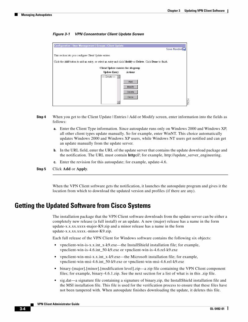
Chapter 3 Updating VPN Client SoftwareManaging Autoupdates
Figure 3-1 VPN Concentrator Client Update Screen
Step 4 When you get to the Client Update | Entries | Add or Modify screen, enter information into the fields as follows:
a. Enter the Client Type information. Since autoupdate runs only on Windows 2000 and Windows XP, all other client types update manually. So for example, enter WinNT. This choice automatically updates Windows 2000 and Windows XP users, while Windows NT users get notified and can get an update manually from the update server.
b. In the URL field, enter the URL of the update server that contains the update download package and the notification. The URL must contain http://; for example, http://update_server_engineering.
c. Enter the revision for this autoupdate; for example, update-4.6.
Step 5 Click Add or Apply.
When the VPN Client software gets the notification, it launches the autoupdate program and gives it the location from which to download the updated version and profiles (if there are any).
Getting the Updated Software from Cisco SystemsThe installation package that the VPN Client software downloads from the update server can be either a completely new release (a full install) or an update. A new (major) release has a name in the form update-x.x.xx.xxxx-major-K9.zip and a minor release has a name in the form update-x.x.xx.xxxx.-minor-K9.zip.
Each full release of the VPN Client for Windows software contains the following six objects:
• vpnclient-win-is-x.x.int_x-k9.exe—the InstallShield installation file; for example, vpnclient-win-is-4.6.int_50-k9.exe or vpnclient-win-is-4.6.rel-k9.exe
• vpnclient-win-msi-x.x.int_x-k9.exe—the Microsoft installation file; for example, vpnclient-win-msi-4.6.int_50-k9.exe or vpnclient-win-msi-4.6.rel-k9.exe
• binary-[major].[minor].[modification level].zip—a zip file containing the VPN Client component files; for example, binary-4.6.1.zip. See the next section for a list of what is in this .zip file.
• sig.dat—a signature file containing a signature of binary.zip, the InstallShield installation file and the MSI installation file. This file is used for the verification process to ensure that these files have not been tampered with. When autoupdate finishes downloading the update, it deletes this file.
3-4VPN Client Administrator Guide
OL-5492-01

Chapter 3 Updating VPN Client SoftwareManaging Autoupdates
• binary_config.ini—a configuration file listing the version available on the update server. Autoupdate uses this file to determine whether it needs to go get the update. If the last major version number (for example, 4.6.1.0) in this file is greater than the current version, autoupdate downloads a full install. If not, then autoupdate looks at the version field. If the version number (for example, 4.6.1.1) is greater than the current version on the PC, autoupdate downloads an update. In any case, after autoupdate finishes downloading the update package, it deletes this file.
• new_update_config.ini—the configuration file that the autoupdate program uses to determine what to download. An administrator who is adding profiles and oem packages to an update must enter the names of the files that contain new or updated profiles and oem packages into this file. Once autoupdate has completed the update, this file becomes update_config.ini on the user’s system.
Of these six objects, an administrator is responsible only for updating the new_update_config.ini file when distributing new or updated profiles. You must not modify the other files in the package. Cisco supplies these files and they are secured by the signature in the sig.dat file.
An update installation consists of a zip file called binary.zip and includes the following files:
Table 3-1 Update Files
Filename Description
CSGina.dll The VPN Client’s GINA file (see “Start Before Logon and GINAs—Windows Only”)
cvpnd.exe The VPN Client Daemon (main daemon), which initializes client service and controls messaging process and flow.
CVPNDRVA.sys The name of the network driver.
ipsecdialer.exe The IPSec module, which obtains network traffic and applies IPSec rules to it.
ipseclog.exe The logging application
ppptool.exe The point-to-point protocol application
SetMTU.exe The application that automatically sets the MTU file size and lets users change the MTU size
vpnclient.exe The VPN Client executable
vpngui.exe The VPN Client graphical user interface program
vpnapi.dll The VPN API library file
ppptool_fc.qm
Language files used in localization
ppptool_jp.qm
qt_jp.qm
vpnclient_fc.qm
vpnclient_jp.qm
3-5VPN Client Administrator Guide
OL-5492-01

Chapter 3 Updating VPN Client SoftwareManaging Autoupdates
Creating the New Update Configuration FileWhen distributing new or modified profiles, the administrator must enter information into the new_update_config.ini file. This file has the same structure as a standard configuration file (see File Format for All Profile Files). Following is a sample new_update_config.ini file.
[Update]Version=1FileName=profiles.zipMaxSize=7000
[Oem]FileName=oem.zipMaxSize=10000
[Transform]Filename=transform.zipMaxSize=12000
[Autoupdate]Required=1
new_update_config.ini File Keywords and Values
Table 3-2 describes each part of the new_update_config.ini file.
Table 3-2 new_update_config.ini File Parameters
Keyword Description Value
[Update] Required keyword to identify update information.
Keep exactly as shown.
Version= Version number of the update package. The administrator can use this parameter to track updates by incrementing the value each time there is a new version of this file.
Enter a value 0 or greater.
Filename= Name of the zip file containing profiles to update or install
Enter the filename (string.zip)
Example: newprofile.zip
MaxSize= Size in bytes of the profile file plus 5000 bytes. This places a limit on how large the file can be.
Enter the size of the file plus 5000 bytes.
Example: 10000
[Oem] Optional keyword to identify OEM information for InstallShield installation, if needed.
Keep exactly as shown.
FileName= Name of the zip file containing oem information to update or install (InstallShield).
Enter the filename (string.zip)
Example: newoem.zip
MaxSize= Size in bytes of the oem file plus 5000 bytes. This places a limit on how large the file can be.
Enter the size of the file plus 5000 bytes.
Example: 12000
3-6VPN Client Administrator Guide
OL-5492-01

Chapter 3 Updating VPN Client SoftwareManaging Autoupdates
Note The transform within the zip file for modifying an MSI installation must be named oem.mst.
Creating the Profile Distribution PackageTo automatically distribute new or updated profiles, use the following procedure:
Step 1 Create the new profile files or modify your current profile files. For information on how to create and modify individual profiles (.pcf files), see “Creating Connection Profiles.”
Step 2 Create a zip file containing the updated profiles; for example, name it profiles.zip.
Step 3 Enter the name of this .zip file into the new_update_config.ini file nd increment the version number under the [Update] section of this file.
Note Although you do not need to update the VPN Client to update the profiles, the update server must also contain all of the required Cisco distributed update files for the VPN Client to accept the new profiles.
Step 4 Copy the new_update_config.ini and the zip file containing the new profiles onto the update server.
[Transform] Optional keyword to identify oem information for MSI installation.
Keep exactly as shown.
FileName= Name of the zip file containing transform information to update or install an update to the MSI installation program.
Enter the filename (string.zip).
Example: newtransform.zip
MaxSize Size in bytes of the transform file plus 5000 bytes. This places a limit on how large the file can be.
Enter the size of the file plus 5000 bytes.
Example: 14000
[Autoupdate] Keyword to identify the autoupdate section.
Keep exactly as shown.
Required= Indicates whether the update or profile update is required.
Enter either 0 or 1.
0 = not required1 = required
Table 3-2 new_update_config.ini File Parameters (continued)
Keyword Description Value
3-7VPN Client Administrator Guide
OL-5492-01

Chapter 3 Updating VPN Client SoftwareHow Automatic Update Works
How Automatic Update WorksThis section provides information for administrators that want to understand more about how this feature works. This is a high-level overview of the autoupdate feature.
The automatic update feature (autoupdate) comprises three processes:
• autoupdate.exe—detects that an update package is on the update server and goes out and retrieves it
• autoinstall.exe—installs the update package
• autoupdategui.exe—handles notifications to the remote user and user responses to notifications
This is what happens:
• A remote user starts up the VPN Client and establishes a tunnel
• The VPN Client software gets the URL of the site containing the update package
• The VPN Client software starts the autoupdate.exe program and gives it the URL for the update package
• Autoupdate determines if an update is necessary by comparing the version information to the one that exists on the VPN Client PC.
• If the update package is later than the one on the PC, autoupdate downloads the update package.
• Autoupdate than lets the remote user know that the update package is available
• The remote user accepts or rejects the update package
• If the remote user accepts the update package, autoupdate verifies the integrity of the update
• Autoupdate unzips the update package then installs it
• If there are any errors, autoupdate or autoinstall logs them in the autoupdate.log and autoinstall.log files found in the Updates folder of the VPN Client folder.
3-8VPN Client Administrator Guide
OL-5492-01

OL-5492-01
C H A P T E R 4
Configuring Automatic VPN InitiationNote Before you begin, we highly recommend that you read “SAFE: Wireless LAN Security in Depth,” which you can access at http://www.cisco.com/go/safe This document analyzes the best practices of implementing security for wireless LANs using VPNs. For a sample configuration demonstrating complete step-by-step instructions covering the group/user configuration on the VPN Concentrator, auto initiation configuration on the VPN Client, and wireless configuration in the Aironet, refer to the TAC technical note “Configuring Automatic VPN Initiation on a Cisco VPN Client in a Wireless LAN Environment.”
Automatic VPN initiation (auto initiation) provides secure connections within an on-site wireless LAN (WLAN) environment through a VPN Concentrator. When auto initiation is configured on the VPN Client, the VPN Client:
• Becomes active immediately when a user starts his/her PC or when the PC becomes active after being on standby or hibernating
• Detects that the PC has an IP address defined as requiring auto initiation
• Establishes a VPN tunnel to the VPN Concentrator defined for its network, prompts the user to authenticate, and allows that user network access
It is worth mentioning that although auto initiation was designed for wireless environments, you can use it in any networking environment. Auto initiation provides a generic way for the VPN Client to auto initiate a connection whether the VPN Client PC is based on specific networks or not.
Figure 4-1 depicts a simple network configuration that employs VPN for securing on-site WLANs. The VPN 3000 Concentrators, which may or may not be using load balancing, provide the gateway between the untrusted and the trusted networks. The DHCP Server can be on either side of the VPN 3000 Concentrator. VPN Client users with laptops that have wireless NIC cards can connect through access points (APs) throughout the campus or building and tunnel to the trusted 30.30.30.x network from the untrusted 10.10.10.x network. The network administrator can set this type of scenario up to be largely transparent to the VPN Client user.
Note You can set up auto initiation configurations that both include and exclude networks for auto initiation.
4-1VPN Client Administrator Guide

Chapter 4 Configuring Automatic VPN Initiation
Figure 4-1 Auto Initiation Scenario
In Figure 4-1 the trusted (wired) network, numbered 30.30.30, is at the top of the diagram with a VPN Concentrator separating it from other networks considered untrusted. The untrusted networks contain wireless subnets, such as 20.20.A.x and 20.20.B.x. Every device on the untrusted network must use a VPN tunnel to access resources on the trusted network. Access to a DHCP server must be available to provide the devices on the untrusted network with initial IP connectivity to the VPN Concentrator. The figure shows the placement of the DHCP server as optional, since it can be placed either on the untrusted network or on the trusted network with DHCP Relay enabled in the VPN Concentrator.
To configure auto initiation for users on the network, you add parameters to the VPN Client’s global profile (vpnclient.ini). For information on how to create or use a global profile, see “Creating a Global Profile.”
Using the VPN Client GUI, users can only enable/disable auto initiation and change the retry interval. These features are available through the Options menu when auto initiation has been configured through the global profile. If auto initiation is not configured, these options do not appear in the Options menu. For a complete explanation of how auto initiation appears to the VPN Client user on a Windows system, see Cisco VPN Client User Guide for Windows, “Using Automatic VPN Initiation.”
The auto initiation feature can be used in WLAN environments containing NIC cards and access points from any vendor.
7172
7
RADIUSServer
DHCPServer
Optionalplacement
30.30.30.3
30.30.30.2
10.10.10.1
30.30.30.1
TrustedUntrusted
FileServer
30.30.30.4 30.30.30.Xnetwork
DHCPServer 10.10.10.2
20.20.A.1(Access point)
20.20.A.Xnetwork
10.10.10.Xnetwork
20.20.A.2(Access point)20.20.A.3
30.30.30.5PN assigned)
VPN 3000s(load balancing)
Routednetwork
20.20.B.1(Access point)
20.20.B.Xnetwork
20.20.B.2(Access point) 20.20.B.3
30.30.30.6(VPN assigned)
4-2VPN Client Administrator Guide
OL-5492-01

Chapter 4 Configuring Automatic VPN InitiationCreating Automatic VPN Initiation in the vpnclient.ini File
Creating Automatic VPN Initiation in the vpnclient.ini FileThis section shows how to create or edit the vpnclient.ini file to activate auto initiation on a VPN Client.
PreparationBefore you begin, you should gather the information you need to configure auto initiation:
• The network IP addresses for the client network
• The subnet mask for the client network
• The names for all connection entries that users are using for their connections
What You Have to DoTo configure auto initiation, you must add the following keywords and values in the [Main] section of the vpnclient.ini global profile file:
• AutoInitiationEnable—enables or disables auto initiation. To enable auto initiation, enter 1. To disable it, enter 0.
• AutoInitiationRetryInterval—specifies the number of minutes to wait before retrying an auto initiation connection. The range is 1 to 10 minutes or 5 to 600 seconds. If you do not include this parameter in the file, the default retry interval is one minute.
• AutoInitiationRetryIntervalType—specifies whether the retry AutoInitiationRetryInterval parameter is displayed in minutes or seconds. The default is minutes.
• AutoInitiationList—provides a series of section names, each of which contains a network address, a subnet mask, a connection entry name, and optionally, a connect flag. You can include a maximum of 64 section (network) entries.
– The section name is the name of an entry in the auto initiation list (within brackets)
– The network and subnet mask identify a subnet
– The connection entry specifies a connection profile (.pcf file) configured for auto initiation.
– The connect flag, if present, indicates the action to take if there is a match. If the Connect parameter is set to 1, the VPN Client should auto initiate; if 0, the VPN Client should not auto initiate. The default setting is 1. This parameter is optional. You can use it to exclude certain network ranges from auto initiation. For example, you might want to address a situation where Mobile IP and VPN software clients co-exist on client PCs and you want the VPN Client to auto initiate when not on a corporate subnet.
In general, when configuring exceptions with the Connect parameter, you might want to place the network ranges you are excluding before those that should auto initiate. More importantly, the software processes the list in the order specified in the vpnclient.ini file. When it matches an entry in the list, the software stops searching and the Connect setting of that entry determines whether to auto initiate or do nothing. So if you put the Connect = 1 entries first, the software never reaches the Connect=0 entries.
It is also important to order the entries in the list by the uniqueness of the network and subnet mask. You should list the more unique entries first. For example, an entry with a network/mask that specifies a match on 10.10.200.* should come before a network/mask that specifies a match on 10.10.*.*. If not, the software matches 10.10.*.* and never reaches 10.10.200.*
Here is an example of an entry in an auto initiation list that excludes the network from auto initiating:
4-3VPN Client Administrator Guide
OL-5492-01

Chapter 4 Configuring Automatic VPN InitiationCreating Automatic VPN Initiation in the vpnclient.ini File
[Franklin]Network=10.10.200.0Subnet=255.255.255.0ConnectionEntry=robronConnect=0
Example 4-1 Section of vpnclient.ini File for Auto Initiation
Suppose a sales manager travels among three locations (Chicago, Denver, and Laramie) within a corporation, attending sales meetings, and wants to securely and easily initiate a wireless connection at these locations. The vpnclient.ini contains the entries shown in this example. The connection entry named in each network section points to the individual’s profile (.pcf) for that on-site wireless LAN network.
[Main]AutoInitiationEnable=1AutoInitiationRetryInterval=3AutoInitiationList=ChicagoWLAN,DenverWLAN,LaramieWLAN[ChicagoWLAN]Network=110.110.110.0Mask=255.255.255.0ConnectionEntry=Chicago (points to a connection profile named chicago.pcf)[DenverWLAN]Network=220.220.220.0Mask=255.255.255.0ConnectionEntry=Denver (points to a connection profile named denver.pcf)[LaramieWLAN]Network=221.221.221.0Mask=255.255.255.0ConnectionEntry=Laramie (points to a connection profile named laramie.pcf)
Example 4-2 Section of vpnclient File for Auto Initiation that excludes and includes auto initiation
In this example, the exceptions (more specific) network addresses appear first in the vpnclient.ini file followed by the connection entries for auto initiation. The connection entries for auto initiation do not need to include the Connect parameter.
[Main]AutoInitiationEnable=1AutoInitiationRetryInterval=3AutoInitiationList=NetworkAExceptions,NetworkA,NetworkBexceptions,NetworkB[NetworkAExceptions]Network=192.168.0.0Mask=255.255.255.0ConnectionEntry=VPNprofileA1Connect=0[NetworkA]Network=192.0.0.0Mask=255.0.0.0ConnectionEntry=VPNprofileA2[NetworkBExceptions]Network=161.200.100.0Mask=255.255.255.0ConnectionEntry=VPNprofileB1Connect=0[NetworkB]Network=161.200.0.0Mask=255.255.0.0ConnectionEntry=VPNprofileB2
4-4VPN Client Administrator Guide
OL-5492-01

Chapter 4 Configuring Automatic VPN InitiationCreating Automatic VPN Initiation in the vpnclient.ini File
Verifying Automatic VPN Initiation ConfigurationTo verify that you have configured auto initiation correctly, open the VPN Client GUI application and perform the following steps:
Step 1 Display the Options menu, and select Automatic VPN Initiation.
Step 2 On the Automatic VPN Initiation dialog, verify that Enable automatic VPN initiation is selected. If not, then click to select it.
Step 3 Click Apply to close the window.
Alternatively you can verify the auto initiation configuration from the command line by executing the following command:
vpnclient verify autoinitconfig
This display shows configuration information for each setting plus a list of your network entries.
4-5VPN Client Administrator Guide
OL-5492-01

Chapter 4 Configuring Automatic VPN InitiationCreating Automatic VPN Initiation in the vpnclient.ini File
4-6VPN Client Administrator Guide
OL-5492-01

OL-5492-01
C H A P T E R 5
Using the VPN Client Command-Line InterfaceThis chapter explains how to use the VPN Client command-line interface (CLI) to connect to a Cisco VPN device, generate statistical reports, and disconnect from the device. You can create your own script files that use the CLI commands to perform routine tasks, such as connect to a corporate server, run reports, and then disconnect from the server.
CLI CommandsThis section lists each command, its syntax, and gives sample output for each command. It is organized by task.
Displaying a List of VPN Client CommandsTo display a list of all VPN Client commands, go to the directory that contains the VPN Client software, and enter the vpnclient command at the command-line prompt:
Note The vpnclient command lists all the commands and parameters available for your platform. Not all commands and parameters are available on all platforms.
5-1VPN Client Administrator Guide

Chapter 5 Using the VPN Client Command-Line InterfaceCLI Commands
Starting a Connection—vpnclient connectTo start a connection, enter the following command:
vpnclient connect <profile> [user <username>][eraseuserpwd | pwd <password>][nocertpwd] [cliauth]
Table 5-1 lists the command options you can use with the vpnclient connect command, includes the task that each option performs, and gives an example of each option.
Table 5-1 Command Line Options
option Definition Notes and Examples
profile Name of the connection entry (.pcf file), that you have previously configured. Required.
If the filename contains spaces, enclose it in double quotes on the command line.
Example: vpnclient connect “to VPN”
user Specifies a username for authentication; with the pwd option, suppresses the username prompt in authentication dialog. Optional.
Updates the username in the .pcf file with this name. However, if the name supplied is not valid, the VPN Client displays the authentication dialog on a subsequent request.
Example: vpnclient connect user robronpwd siltango toVPN
eraseuserpwd Erases the user password saved on the Client PC thereby forcing the VPN Client to prompt for a password. Optional.
You might have configured a connection with Saved Password to suppress a password prompt when connecting using a batch file. You can then use the eraseuserpwd to return to the more secure state of requiring password input from the console when connecting.
Example: vpnclient connect eraseuserpwd toVPN
pwd Specifies a password for authentication; with the user option on the command line, suppresses the password prompt in authentication dialog. Optional.
If the password supplied is not valid, the VPN Client displays the authentication dialog on a subsequent request. After encrypting and using the password for the connection, the VPN Client clears the password in the .pcf file. Using this option on the command line compromises security and is not recommended.
Example: vpnclient connect user robronpwd siltango toVPN
nocertpwd Suppresses prompting for a certificate password.Optional.
Example: vpnclient connect nocertpwd toVPN
cliauth (Windows platforms only)
Prompts for authentication information on the command line. Eliminates the GUI prompt that displays during a connection request from the command line.
The VPN client prompts for username and password. The password is displayed as asterisks.
Example: vpnclient connect cliauth toVPN
5-2VPN Client Administrator Guide
OL-5492-01

Chapter 5 Using the VPN Client Command-Line InterfaceCLI Commands
Example 5-1 vpnclient connect Command
This example shows the vpnclient connect command that connects you to the Engineering Server using the profile name “engineering”
At this point, the VPN Client displays an authentication dialog box that prompts for your username and password.
Figure 5-1 Authenticating a User
After you enter your name and password, authentication succeeds, and the command continues executing.
stdin Causes the CLI to read input from the standard input pipe instead of from the console.
This option enables third party software to provide input directly to the CLI
Example: vpnclient connect toVPN stdin
sd Suppresses the “Do you wish to disconnect your Dial-Up Networking connection?” message that occurs when one is using Microsoft Dial-Up Networking.
Post version 4.0.3D this switch behaves as documented here.
Example: vpnclient connect toVPN sd
Table 5-1 Command Line Options
option Definition Notes and Examples
5-3VPN Client Administrator Guide
OL-5492-01

Chapter 5 Using the VPN Client Command-Line InterfaceCLI Commands
Example 5-2 vpn connect Command Using cliauth
Alternatively, to suppress the User Authentication window shown in Example 4-1, you can use the cliauth parameter. The command line then prompts for username and password. Using the cliauth parameter avoids having a password display in clear text on the command line.
Example 5-3 vpnclient connect Command Using Parameters
The following command connects to the remote network without user interaction. Notice that the password appears on the command line in clear text.
Displaying a Notification—vpnclient notifyWhen you connect, you can display a notification using the vpnclient notify command:
vpnclient notify
Example 5-4 vpnclient notify Command
The following session shows how to use the vpnclient notify command to display a notification from a network administrator.
5-4VPN Client Administrator Guide
OL-5492-01

Chapter 5 Using the VPN Client Command-Line InterfaceCLI Commands
C:\Program Files\Cisco Systems\Vpn Client\vpnclient notifyCisco Systems VPN Client Version 4.0Copyright <C> 1998-2003 Cisco Systems, Inc. All Rights Reserved.Client Type<s>: WindowsRunning on: 5.0.2195
Notification:Your network administrator has placed an update of the Cisco Systems VPN Client at the following location:http://www.mycompany.com/clientupdate
Displaying an Automatic VPN Initiation Configuration—Windows OnlyTo display your configuration for auto initiation, enter the following command:
vpnclient verify autoinitconfig
Note If the mask in the output display does not match the value in the profile, then the mask is invalid. An invalid mask is displayed as 255.255.255.255
Example 5-5 vpnclient verify Command
The following command shows your auto initiation configuration for one access point.
Suspending/Resuming Stateful Firewall (Windows Only)To suspend the stateful firewall, enter the following command:
vpnclient suspendfw
To resume a suspended stateful firewall, enter the following command;
vpnclient resume.fw
Example 5-6 Suspending and Resuming Stateful Firewall
The following commands control the setting of the stateful firewall. The first command output shows the response displayed when the stateful firewall is not enabled when the command is executed. The next two commands, executed after enabling the stateful firewall, first suspend the firewall and then resume it.
5-5VPN Client Administrator Guide
OL-5492-01

Chapter 5 Using the VPN Client Command-Line InterfaceCLI Commands
Note If you reboot the PC after suspending the stateful firewall, the software restores the Stateful Firewall setting to enable and this will block traffic.
Ending a Connection—vpnclient disconnectTo disconnect from your session, enter the following command:
vpnclient disconnect
Example 5-7 vpnclient disconnect Command
The following command disconnects you from your secure connection.
Displaying Information About Your Connection—vpnclient statTo generate status information about your connection, enter the following command:
vpnclient stat [reset] [traffic] [tunnel] [route] [firewall] [repeat]
5-6VPN Client Administrator Guide
OL-5492-01

Chapter 5 Using the VPN Client Command-Line InterfaceCLI Commands
When entered without any of the optional parameters, the vpnclient stat command displays all status information. The following parameters are optional:
The following examples show sample output from the vpnclient stat command. For more information on statistical output, see VPN Client User Guide for Windows.
Option Definition Examplereset Restarts all connection counts from zero. SA stats
are not reset.vpnclient stat reset
traffic Displays a summary of bytes in and out, packets encrypted and decrypted, packets bypassed, and packets discarded.
vpnclient stat traffic
tunnel Displays IPSec tunneling information. vpnclient stat tunnelroute Displays configured routes. vpnclient stat routesfirewall Identifies the type of firewall in use and displays
information generated by the firewall configuration. This option is available only on Windows platforms
vpnclient stat firewall
repeat Provides a continuous display, refreshing it every few seconds. To end the display, press <ctrl-C>.
To first reset the statistics information, use the reset option with the repeat option (see examples).
vpnclient stat traffic repeatvpnclient stat repeatvpnclient stat reset traffic repeatvpnclient stat reset repeat
5-7VPN Client Administrator Guide
OL-5492-01

Chapter 5 Using the VPN Client Command-Line InterfaceCLI Commands
Example 5-8 vpnclient stat Command
Following is an example of the information that the vpnclient stat command displays.
Example 5-9 vpnclient stat reset Command
The vpnclient stat reset command resets all connection counters.
5-8VPN Client Administrator Guide
OL-5492-01

Chapter 5 Using the VPN Client Command-Line InterfaceCLI Commands
Example 5-10 vpnclient stat traffic Command
Here is a sample of the information that the vpnclient stat traffic command generates.
Example 5-11 vpnclient stat tunnel Command
To display only tunneling information, use the vpnclient stat tunnel command. Here is a sample.
Example 5-12 vpnclient stat route Command
The vpnclient stat route command displays information similar to the following display.
5-9VPN Client Administrator Guide
OL-5492-01

Chapter 5 Using the VPN Client Command-Line InterfaceCLI Commands
Example 5-13 vpnclient stat firewall Command—Windows Only
The vpnclient stat firewall command displays information similar to the following display.
Note The maximum size of any VPN Client statistics count is 4,294,967,296. Once the VPN Client software reaches this limit, the statistics count rolls back to zero and starts again.
5-10VPN Client Administrator Guide
OL-5492-01

Chapter 5 Using the VPN Client Command-Line InterfaceReturn Codes
Return CodesThis section lists the error levels (return codes) that you can receive when using the VPN Client command-line interface.
Return Code Message Meaning
200 SUCCESS_START The VPN Client connection started successfully.
201 SUCCESS_STOP The VPN Client connection has ended.
202 SUCCESS_STAT The VPN Client has generated statistical information successfully.
203 SUCCESS_ENUMPPP The enumppp command has succeeded. This command lists phone book entries when connecting to the Internet via dial-up.
1 ERR_UNKNOWN An unidentifiable error has occurred during command-line parsing.
2 ERR_MISSING_COMMAND Command is missing from command-line input.
3 ERR_BAD_COMMAND There is an error in the command entered; check spelling.
4 ERR_MISSING_PARAMS The command-line input is missing required parameter(s).
5 ERR_BAD_PARAMS The parameter(s) in the command input are incorrect; check spelling.
6 ERR_TOO_MANY_PARAMS The command-line input contains too many parameters.
7 ERR_NO_PARAMS_NEEDED The command entered does not require parameters.
8 ERR_ATTACH_FAILED Interprocess communication error occurred attaching to the generic interface.
9 ERR_DETACH_FAILED Interprocess communication error occurred detaching from the generic interface.
10 ERR_NO_PROFILE The VPN Client failed to read the profile.
11 ERR_PWD_MISMATCHED Reserved
12 ERR_PWD_TOO_LONG The password contains too many characters. The group password limit is 32 characters; the certificate password limit is 255 characters.
13 ERR_TOO_MANY_TRIES Attempts to enter a valid password have exceed the amount allowed. The limit is three times.
14 ERR_START_FAILED The connection attempt has failed; unable to connect.
15 ERR_STOP_FAILED The disconnect action has failed; unable to disconnect.
16 ERR_STAT_FAILED The attempt to display connection status has failed.
17 ERR_ENUM_FAILED Unable to list phonebook entries.
5-11VPN Client Administrator Guide
OL-5492-01

Chapter 5 Using the VPN Client Command-Line InterfaceReturn Codes
18 ERR_COMMUNICATION_FAILED A serious interprocess communication error has occurred.
19 ERR_SET_HANDLER_FAILED Set console control handler failed.
20 ERR_CLEAR_HANDLER_FAILED Attempt to clean up after a user break failed.
21 ERR_OUT_OF_MEMORY Out of memory. Memory allocation failed.
22 ERR_BAD_INTERFACE Internal display error.
23 ERR_UNEXPECTED_CALLBACK In communicating with the Connection Manager, an unexpected callback (response) occurred.
24 ERR_DO_NOT_CONTINUE User quit at a banner requesting “continue?”
25 ERR_GUI_RUNNING Cannot use the command-line interface when connected through the graphical interface dialer application.
26 ERR_SET_WORK_DIR_FAILED The attempt to set the working directory has failed. This is the directory where the program files reside.
27 ERR_NOT_CONNECTED Attempt to display status has failed because there is no connection in effect.
28 ERR_BAD_GROUP_NAME The group name configured for the connection is too long. The limit is 128 characters.
29 ERR_BAD_GROUP_PWD The group password configured for the connection is too long. The limit is 32 characters.
30 ERR_BAD_AUTHTYPE The authentication type configured for the connection is invalid.
31 RESERVED_01 Reserved.
32 RESERVED_02 Reserved.
33 ERR_COMMUNICATION_TIMED_OUT Interprocess communication timed out.
34 ERR_BAD_3RD_PARTY_DIAL Failed to launch a third-party dialer.
35 ERR_DAEMON_NOT_RUNNING (CVPND.EXE)—Non-Windows only
Connection needs to be established for command to execute.
36 ERR_DAEMON_ALREADY_RUNNING (CVPND.EXE)—Non-Windows only
Command cannot work because connection is already established.
Return Code Message Meaning
5-12VPN Client Administrator Guide
OL-5492-01

Chapter 5 Using the VPN Client Command-Line InterfaceApplication Example—Windows Only
Application Example—Windows OnlyHere is an example of a DOS batch file (.bat) that uses CLI commands to connect to the corporate office from a branch office, run an application, and then disconnect from the corporate site.
runxls.batrem assume you have generated a report in the middle of the night that needs rem to be sent to the corporate office.
rem .. generate report.xls . .
rem connect to the home officevpnclient connect myprofile user admin pwd admin
rem check return code from vpnclient call....if %errorlevel% neq 200 goto failedrem if okay continue and copy report
copy report.xls \\mycorpserver\directory\overnight_reports /v
rem now disconnect the VPN connectionvpnclient disconnectecho Spreadsheet uploadedgoto end:failedecho failed to connect with error = %errorlevel%:end
5-13VPN Client Administrator Guide
OL-5492-01

Chapter 5 Using the VPN Client Command-Line InterfaceApplication Example—Windows Only
5-14VPN Client Administrator Guide
OL-5492-01

Cisco VPNOL-5491-01
C H A P T E R 6
Managing Digital Certificates from the Command LineThis chapter describes how use the command-line interface to manage digital certificates in your certificate store. Your certificate store is the location in your local file system for storing digital certificates. The store for the VPN Client is the Cisco store.
Setting Certificate KeywordsTo use certificates for authentication, you must correctly set all keywords that apply to certificates in your user profile. Check your settings for the following keywords:
• AuthType = 3 (certificate authentication)
• CertStore = 1 (Cisco certificate store)
• CertName = Common Name (This must be the same common name entered for a certificate.)
For more information on setting parameters in your user profile, see “User Profiles.”
Certificate Command SyntaxThe command line interface for certificate management operates in two ways:
• The standard UNIX shell or the DOS command-line prompt at which you enter all arguments for a given command on the same line.
cisco_cert_mgr -U -op enroll -f filename -chall challenge_phrase
• A prompting mode in which you enter minimum arguments for a given command and are prompted for any remaining information.
The minimum command line argument follows this basic form:
cisco_cert_mgr -U -op operationcisco_cert_mgr -R -op operationcisco_cert_mgr -E -op operation
Where:
– -U applies to the user or private certificate.
You can use the -U flag for all certificate management command operations, except enroll_resume.
6-1 Client User Guide for Linux and Solaris

Chapter 6 Managing Digital Certificates from the Command LineCertificate Contents
– -R applies to the root certificate or certificate authority (CA) certificate.
You can use the -R flag for list, view, verify, delete, export, import, and change password operations.
– -E applies to certificate enrollment.
You can only use the -E flag with list and delete, and you must specify it using the enroll_resume operation.
The operation for the specified certificate follows the -op argument. Valid operations for the certificate manager command are list, view, verify, delete, export, import, enroll, enroll_file, and enroll_resume. For more information on these operations, see the “Certificate Management Operations.”
For example, if you enter the following command:
cisco-cert-mgr -R -op import
Certificate manager prompts you for the name of the file to import.
Certificate ContentsThis section describes the type of information contained in a digital certificate.
A typical digital certificate contains the following information:
• Common name—The name of the owner, usually both the first and last names. This field identifies the owner within the Public Key Infrastructure (PKI) organization.
• Department—The name of the owner’s department. This is the same as the organizational unit.
– If you are connecting to a VPN 3000 concentrator, this field must match the Group Name configured for the owner in the concentrator.
• Company—The company in which the owner is using the certificate. This is the same as the organization.
• State—The state in which the owner is using the certificate.
• Country—The two-character country code in which the owner’s system is located.
• Email—The e-mail address of the owner of the certificate.
• Thumbprint—An MD5 hash of the certificate’s complete contents. The thumbprint provides a means for validating the authenticity of the certificate. For example, if you contact the issuing CA, you can use this identifier to verify that this certificate is the correct one to use.
• Key size—The size of the signing key pair in bits.
• Subject—The fully qualified domain name (FQDN) of the certificate’s owner. This field uniquely identifies the owner of the certificate in a format that can be used for LDAP and X.500 directory queries. A typical subject includes the following fields:
– common name (cn)
– organizational unit, or department (ou)
– organization or company (o)
– locality, city, or town (l)
– state or province (st)
– country (c)
– e-mail address (e)
6-2Cisco VPN Client User Guide for Linux and Solaris
OL-5491-01

Chapter 6 Managing Digital Certificates from the Command LineCertificate Passwords
Other items might be included in the Subject, depending on the certificate.
• Serial number—A unique identifier used for tracking the validity of the certificate on the certificate revocation lists (CRLs).
• Issuer—The FQDN of the source that provided the certificate.
• Not before—The beginning date that the certificate is valid.
• Not after—The end date beyond which the certificate is no longer valid.
The following output is an example of the type of information contained in a digital certificate:
Common Name: Fred FlintstoneDepartment: Rock yardCompany: Stone Co.State: (null)Country: (null)Email: [email protected] Print: 2936A0C874141273761B7F06F8152CF6Key Size: 1024Subject:[email protected],cn=Fred Flinstone,ou=Rockyard,o=Stone Co. l=BedrockSerial #: 7E813E99B9E0F48077BF995AA8D4ED98Issuer: Stone Co.Not before: Thu May 24 18:00:00 2001Not after: Mon May 24 17:59:59 2004
Certificate PasswordsEach digital certificate is protected by a password. Many operations performed by the certificate management command require that you enter the password before the operation can take place.
The operations that require you to enter a password are:
• Delete
• Import
• Export
• Enroll
Note For the enroll operation, the password to protect the digital certificate is a separate password from the optional challenge password that you enter for the server certificate.
You are prompted for any passwords that are required to complete the command. You must enter the password and verify the password again before the command can execute. If the password is not accepted, you must re-enter the command.
When you establish a VPN connection with a certificate, a certificate password is also required.
All passwords can be up to 32 alphanumeric characters in length, and are case sensitive.
6-3Cisco VPN Client User Guide for Linux and Solaris
OL-5491-01

Chapter 6 Managing Digital Certificates from the Command LineCertificate Tags
Certificate TagsA certificate tag is the identifier for each unique certificate. Each certificate added to the certificate store is assigned a certificate tag. An enroll operation also generates a certificate tag, even if the enroll operation does not complete.
Some certificate management operations require that you enter a certificate tag argument before the operation can take place. Operations that require certificate tags are listed in Table 6-1. Use the list operation to find your certificate tag.
To enter a certificate tag argument, use the -ct command followed by the certificate identifier, listed as -ct Cert # next to the operation.
The following example shows the view command with a required certificate tag:
cisco_cert_mgr -U -op view -ct 0
Where the operation is view, and the certificate tag is 0.
If you do not enter the -ct argument and certificate tag, the command line prompts you for them. If you enter an invalid certificate tag, the command line lists all certificates in the certificate store, and prompts you again for the certificate tag.
Certificate Management OperationsList all certificate management operations on the command line following the minimum command line argument. Valid operation strings allow you to list, view, verify, delete, export, import, and enroll digital certificates in your store.
The following is an example of a certificate management command with the list operation, and a sample output.
cisco_cert_mgr -U -op list
cisco_cert_mgr Version 3.0.7
Cert # Common Name 0 Fred Flinstone 1 Dino
Table 6-1 describes the operations that can be used with the certificate management command.
Table 6-1 Parameters for the cert_mgr Command
Parameter Description
list Lists all certificates in the certificate store. Each certificate in the list is identified by a unique certificate tag (Cert #).
view -ct Cert # Views the specified certificate. You must enter a certificate tag.
6-4Cisco VPN Client User Guide for Linux and Solaris
OL-5491-01

Chapter 6 Managing Digital Certificates from the Command LineCertificate Management Operations
verify -ct Cert # Verifies that the specified certificate is valid. You must enter a certificate tag.
If the certificate is verified, the message ‘Certificate Cert # verified’ appears.
If the certificate fails verification for any reason, the message ‘Certificate Cert # failed verification’ appears. Following this message is a text string that describes the reason for the failure.
delete -ct Cert # Deletes the specified certificate. You must enter a certificate tag.
export -ct Cert # -f filename Exports the identified certificate from the certificate store to a specified file. You must enter a certificate tag and a filename. If either is omitted, the command line prompts you for them.
You must enter the full path of the destination. If you enter only the filename, the file is placed in your working directory.
import -f filename Imports a certificate from a specified file to the certificate store.
This operation requires two different passwords: the password that protects the file (assigned by your administrator), and the password you select to protect the certificate.
enroll-cn common_name-ou organizational_unit-o organization-st state-c country-e email -ip IP_Address-dn domain_name-caurl url_of _CA-cadn domain_name[-chall challenge_phrase]
For user certificates only.
Obtains a certificate by enrolling you with a Certificate Authority (CA) over the network.
Enter each keyword individually on the command line.
See the “Enrolling Certificates” for more information.
You can obtain a challenge phrase from your administrator or from the CA.
enroll_file-cn common_name-ou organizational_unit -o organization-st state-c country-e email -ip IP_Address-dn domain_name-f filename-enc [ base64 | binary ]
For user certificates only.
Generates an enrollment request file that you can e-mail to the CA or paste into a webpage form. When CA generates the certificate, you must import it using the import operation.
See the “Enrolling Certificates” for more information.
Table 6-1 Parameters for the cert_mgr Command (continued)
Parameter Description
6-5Cisco VPN Client User Guide for Linux and Solaris
OL-5491-01

Chapter 6 Managing Digital Certificates from the Command LineEnrolling Certificates
Enrolling CertificatesA Certificate Authority (CA) is a trusted organization that issues digital certificates to users for verifying that they are who they claim to be. The certificate enrollment operations allow you to obtain your certificate from a CA over the network or from an enrollment request file.
There are three types of certificate enrollment operations.
• The enroll operation allows you to obtain a certificate by enrolling with a CA over the network. You must enter the URL of the CA, the domain name of the CA, and the common name.
• The enroll_file operation generates an enrollment request file that you can e-mail to a CA or post into a webpage form. You must enter a filename, a common name, and an encoding type.
With the enroll and enroll_file operations, you can include keywords to supply additional information (see Table 6-2).
• The enroll_resume operation resumes an interrupted network enrollment. You must enter the -E argument and a certificate tag. To find your certificate tag, use the list operation.
Enrollment OperationsTo use enrollment operations, enter the certificate manager command, an enroll operation, and the associated keywords on the command line.
• The following example shows the enroll command with the minimum required keywords for common name (-cn), URL of the CA (-caurl) and domain name of the CA (-cadn):
cisco_cert_mgr -U -op enroll -cn Ren Hoek -caurl http://172.168.0.32/certsrv/mscep/mscep.dll -cadn nobody.fake
• The following example shows the enroll_file command with the minimum required keywords for filename (-f), common name (-cn), and encoding type (-enc):
cisco_cert_mgr -U -op enroll_file -f filename -cn Ren Hoek -enc base64
• The following example shows the enroll_file command with the required minimum arguments and additional keywords:
cisco_cert_mgr -U -op enroll_file -f filename -cn Ren Hoek -ou Customer Service -o Stimpy, Inc, -st CO -c US -e [email protected] -ip 10.10.10.10 -dn fake.fake -enc binary
• The following example shows the enroll_resume command:
cisco_cert_mgr -E -op enroll_resume -ct 4
enroll_resume -E -ct Cert # You cannot use this operation with user or root certificates.
Resumes an interrupted network enrollment. You must enter the -E argument and a certificate tag.
changepassword -ct Cert #
Changes a password for a specified digital certificate. You must enter a certificate tag.
You must enter the current password before you select the new password and confirm it.
Table 6-1 Parameters for the cert_mgr Command (continued)
Parameter Description
6-6Cisco VPN Client User Guide for Linux and Solaris
OL-5491-01

Chapter 6 Managing Digital Certificates from the Command LineEnrolling Certificates
Table 6-2 describes options for the enroll, enroll_file, and enroll_resume operations.
Enrollment Troubleshooting Tip
If the enrollment request for a user certificate, using either the enroll or enroll_file operation, generates a CA certificate instead of a user certificate, the CA might be overwriting some of the distinguished naming information. This might be caused by a configuration issue on the CA, or a limitation of how the CA responds to enrollment requests.
The common name and subject in the enrollment request must match the certificate generated by the CA for the VPN Client to recognize it as the user certificate you requested. If it does not match, the VPN Client does not install the new user certificate as requested.
To check for this problem, view the enrollment request on the VPN Client and compare the common name and subject lines with a view of the certificate from the CA. If they do not match, then the CA is overwriting information from the client request.
To work around this issue, use the invalid certificate as an example and create an enrollment request that matches the output of the CA certificate.
Note If the CA’s certificate contains multiple department (multiple ou fields), you can add multiple departments to the VPN Client enrollment request by using the plus sign (+) between the department fields.
Table 6-2 Keywords for Enrollment Operations
Parameter Description
-cn common_name The common name for the certificate.
-ou organizational_unit The organizational unit for the certificate.
-o organization The organization for the certificate.
-st state The state for the certificate.
-c country The country for the certificate.
-e email The user e-mail address for the certificate.
-ip IP_Address The IP address of the user’s system.
-dn domain_name The FQDN of the user’s system.
-caurl url_of_CA The URL or network address of the CA.
-cadn domain_name The CA’s domain name.
[-chall challenge_phrase ] You can obtain the challenge phrase from your administrator or from the CA.
-enc [ base64 | binary ] Select encoding of the output file. The default is base64.
• base64 is an ASCII-encoded PKCS10 file that you can display because it is in a text format. Choose this type when you want to cut and paste the text into the CA’s website.
• binary is a base-2 PKCS10 (Public-Key Cryptography Standards) file. You cannot display a binary-encoded file.
6-7Cisco VPN Client User Guide for Linux and Solaris
OL-5491-01

Chapter 6 Managing Digital Certificates from the Command LineEnrolling Certificates
6-8Cisco VPN Client User Guide for Linux and Solaris
OL-5491-01

OL-5492-01
C H A P T E R 7
Customizing the VPN Client SoftwareThis chapter explains how to replace the Cisco Systems brand with your own organization’s brand. When you install and launch the VPN Client software, you see your own organization name, program name, and application names on menus, windows, dialogs, and icons.
For the Windows platform, it also explains how to set up the software so that your users can install it automatically without being prompted. This feature is called silent install.
To customize the VPN Client software, you create your own distribution image combining the following elements, which this chapter describes.
For all platforms, you can customize the following:
• Cisco Systems image that you receive on the Cisco Systems software distribution CD.
• Your own portable network graphics (PNG) (Table 7-2) and icon files to replace the Cisco Systems brand.
• A vpnclient.ini file for configuring the VPN Client software globally (see Chapter 2, “Preconfiguring the VPN Client for Remote Users”).
• Individual profile (.pcf) files for each connection entry (see Chapter 2, “Preconfiguring the VPN Client for Remote Users”).
For the Windows platform, you can also customize the following:
• An oem.ini file that you create. Cisco supplies a sample oem.ini file that you can use as a template and customize.
• setup.bmp—a bitmap file that displays on the first InstallShield® window when you install the VPN Client. (InstallShield only)
These elements should all be in the same directory and folder. Because some of the files may be too large to distribute the oem software on diskettes, we recommend that you make a CD ROM distribution image.
7-1VPN Client Administrator Guide

Chapter 7 Customizing the VPN Client SoftwareCustomizing the VPN Client GUI for Windows
Customizing the VPN Client GUI for WindowsThis section describes how to customize the VPN Client GUI for the Windows platform. To customize the GUI for the Mac OS X platform, see Customizing the VPN Client GUI for Mac OS X, page 7-18.
Customizing the VPN Client occurs when the VPN Client and installation program see a text file called oem.ini on your distribution image. The oem.ini file is patterned after Microsoft standard initialization files. You create the oem.ini file and supply your own text, PNG files, and icon files. When present, the oem.ini, PNG, and icon files are read when you first start the VPN Client. Since the VPN Client software reads these files when it first starts, the changes to them take effect only after you restart the VPN Client application.
This chapter contains the following sections:
• Areas Affected by Customizing the VPN Client
• Creating the oem.ini File
• Installing the VPN Client Without User Interaction
• Customizing the VPN Client Using an MSI Transform
Areas Affected by Customizing the VPN ClientCustomizing replaces the following screen text, bitmaps, and icons.
• Brand names on dialog boxes
• Product names on dialog boxes
• Organization logo on all dialog boxes
• Graphic at the left end of the title bar
• Icons on the system tray (at the bottom right of the screen) and the desktop (shortcut)
Installation Bitmap
The InstallShield uses a bitmap when installing the VPN Client software: the setup bitmap (setup.bmp).
Figure 7-1 shows the setup bitmap that displays as the first screen during installation via InstallShield.
7-2VPN Client Administrator Guide
OL-5492-01

Chapter 7 Customizing the VPN Client SoftwareCustomizing the VPN Client GUI for Windows
Figure 7-1 Setup Bitmap
Program Menu Titles and Text
After installation, your organization or company, product, and application names appear in the Cisco Systems VPN Client applications menu. (See Figure 7-2.)
Figure 7-2 Applications menu
7-3VPN Client Administrator Guide
OL-5492-01

Chapter 7 Customizing the VPN Client SoftwareCustomizing the VPN Client GUI for Windows
VPN Client
Figure 7-3 shows a lock image (title_bar.png), window title (AppNameText in the oem.ini file), and organization logo (logo.png file). The oem.ini file can replace the window title, the image at the left end of the title bar, and the organization or company logo in the VPN Client software. It can replace the open lock and closed lock icons in the system tray (see Figure 7-4 and Figure 7-5).
Figure 7-3 Three Types of Branding Changes
Figure 7-4 Closed Lock Icon on System Tray (connected.ico)
Figure 7-5 Open Lock Icon on the System Tray (unconnected.ico)
1 Title bar lock image (title_bar.png) 3 Organization logo (logo.png)
2 Window title (oem.ini file)60
706
1 2 3
7-4VPN Client Administrator Guide
OL-5492-01

Chapter 7 Customizing the VPN Client SoftwareCustomizing the VPN Client GUI for Windows
Setup Bitmap—setup.bmp
The InstallShield version of VPN Client includes a bitmap on the distribution CD that is not in the oem.ini file: setup.bmp. You can substitute your own image for this .bmp file, as long as you keep the current filename (setup.bmp) and make sure that the file is in the same directory and folder as the oem.ini file. This file displays a logo on the window when you start the InstallShield installation program. The size of the Cisco Systems setup bitmap is 330x330 pixels and it uses 256 colors.
Creating the oem.ini File
Your distribution CD must contain the oem.ini file for customizing. The oem.ini file contains the locations and names of bitmaps, icons, window titles, and screen text needed for customizing, all of which need to be in the same directory. When you install or start the VPN Client, the software checks to see if there is an oem.ini file. If so, the software scans it for bitmaps, icons, and text. If the oem.ini file lacks an element (for example, text for the product name), then the software uses whatever you have specified in the default section of the file. If no oem.ini file exists, the software defaults to Cisco Systems bitmaps, icons, and text.
Use Notepad or another ASCII text editor to create the oem.ini file and enter brand text and the names of your bitmap and icon files. See Table 7-1.
Note You can edit the oem.ini file that Cisco Systems supplies.
The format of the oem.ini file is the same as a standard Windows ini file:
• Use a semicolon (;) to begin a comment.
• Set values by entering keyword=value.
• If you don’t specify a value for a keyword, the application uses the default.
• Keywords are not case-sensitive, but using upper and lowercase makes them more readable.
Sample oem.ini File
; This is a sample oem.ini file that you can use to overwrite Cisco Systems; brand name on windows, bitmaps, and icons with your organization’s brand; name.;; This file has five sections: [Main],[Brand], [Default], [Dialer], and [SetMTU]; Each section has keywords designating parts of the interface that the file replaces.;; The [Main] section determines whether kerberos uses TCP or UDP (the default).
[Main]DisableKerberosOverTCP = 1
; The [Brand] section controls window titles during installation and in the; destination folder for the product and applications. ;[Brand]
CompanyText = Wonderland University
ProductText = Wonderland Client
;; The [Default] section establishes the default bitmap and icon to use if
7-5VPN Client Administrator Guide
OL-5492-01

Chapter 7 Customizing the VPN Client SoftwareCustomizing the VPN Client GUI for Windows
; assignments are left blank. This section also sets up silent installation. ; Silent mode installation proceeds without user intervention.;[Default]SilentMode = 1InstallPath = C:\Program Files\Wonderland University\Wonderland ClientDefGroup = Wonderland ClientReboot = 1;; The [Dialer] section controls the text and icons for the dialer software.; AppNameText appears on the application selection menu. DialerBitMap; appears on connection windows. AllowSBLLaunches controls whether a remote user can; launch an application before connecting and logging on to a Windows NT platform.;[Dialer]MainIcon=is_install.icoAppNameText = Wonderland DialerAllowSBLLaunches = 0;; The [Set MTU] section controls the text and icon for the; Set MTU applications. AppNameText appears on the application ; selection menu and the title screen. MainIcon appears on the window title.; bar.;[Set MTU]AppNameText = MTU Setter ApplicationMainIcon = MtuIcon.icoAutoSetMtu = 1SetMtuValue = 1300VAMtu=1252MTUAdjustmentOverride = 144
oem.ini File Keywords and Values
Table 7-1 describes each part of the oem.ini file.
Table 7-1 oem.ini File Parameters
Keyword Description Value
[Main] Optional field that identifies a section of the OEM.ini file to address special circumstances.
Keep exactly as shown.
DisableKerberosOverTCP= InstallShield only
When installing the VPN Client on Windows, the installation program sets a registry value that forces windows to use Kerberos over TCP instead of UDP, the default. Some NAT devices, such as Linksys, do not support out-of-order IP fragments, which breaks Kerberos. With TCP, fragmentation is not required.
After the keyword and equal sign, enter either 1 or 0.
0 = keep the default, which is to force Kerberos to use TCP.
1 = prevent Kerberos from using TCP.
[Brand] Required field that identifies the branding text that appears on window titles and descriptions throughout the client application.
Keep exactly as shown, as the branding section of the file.
CompanyText= Identifies the name of your organization. If not present, the default is “Cisco Systems.”
After the keyword and equal sign, enter the organization’s name. The name can contain spaces and is not case sensitive.
7-6VPN Client Administrator Guide
OL-5492-01

Chapter 7 Customizing the VPN Client SoftwareCustomizing the VPN Client GUI for Windows
ProductText= Identifies the name of the application. If not present, the default is “VPN Client.”
After the keyword and equal sign, enter the product name. The name can contain spaces and is not case sensitive.
[Default] Required field that identifies the section that contains names of default bitmap and icon to use if values are blank.
Enter exactly as shown, as the default section of the file.
SilentMode= InstallShield only
Specifies whether to activate silent installation.
After the keyword and equal sign, enter either 0 or 1. 1 activates silent installation:
0 = prompt the user during installation.
1= do not prompt the user during installation.
InstallPath= InstallShield only
Identifies the directory into which to install the client software.
After the keyword and equal sign, enter the name of the directory in the suggested format:
root:\programs\company\product
DefGroup= InstallShield only
Identifies the name of the folder to contain the client software.
After the keyword and equal sign, enter the name of the destination folder in the suggested format:
foldername
Reboot= InstallShield only
Specifies whether to restart the system after the silent installation. If SilentMode is on (1) and Reboot is 1, the system automatically reboots after installation finishes.
After the keyword and equal sign, enter 0, 1, or 2:
0 = display the reboot dialog.
1 (and SilentMode = 1) = automatically reboot the system when installation finishes.
2 (and SilentMode = 1) = do not reboot after installation finishes.
[Dialer] Required field that identifies the section that contains the name of the Dialer application, the bitmap to use on the connections window, and the connection icons.
Enter exactly as shown, as the Dialer section of the file.
AppNameText= Identifies the name of the dialer application. After the keyword and equal sign, enter the name of the dialer application. The name can contain spaces and is not case sensitive.
MainIcon= This is used only by InstallShield for shortcuts to the vpngui.exe.
After the keyword and equal sign, enter the name of the icon file.
AllowSBLLaunches InstallShield only
Specifies whether a VPN Client user is allowed to launch a third party application before logging on to a Windows NT platform.
After the keyword and equal sign, enter 1 to enable or 0 to disable this feature. The default is 0 (to disable). (See Note after table.)
[Set Mtu] Required field that identifies the section that contains the name of the Set MTU application, the name of the Set MTU icon, and other settings.
Enter exactly as shown; identifies the Set MTU section of the file.
Table 7-1 oem.ini File Parameters (continued)
Keyword Description Value
7-7VPN Client Administrator Guide
OL-5492-01

Chapter 7 Customizing the VPN Client SoftwareCustomizing the VPN Client GUI for Windows
Note When AllowSBLLaunches is 0, “Allow launching of third party applications before logon” under Windows Logon Properties is unavailable. There might be cases when you need to launch an application before starting your connection, for example, to authenticate your access credentials. In this case you can use the following procedure:In the VPN Dialer program, choose Options > Windows Logon Properties.Uncheck Disconnect VPN connection when logging off.Log out.Log in with cached credentials.Make your VPN Dialer connection.Log out.Log in again while already connected.
Table 7-2 lists the GUI image (portable network graphic) files that the VPN Client uses. If you want to replace any of them with your own image files, you must name your image files exactly as shown in the list; otherwise, the VPN Client GUI does not recognize them.
AppNameText= Identifies the name of the Set MTU application. After the keyword and equal sign, enter the name you want to give to this application. The name can contain spaces and is not case sensitive.
MainIcon= Identifies the icon for the Set MTU title bar, About window, and applications menu. There are two sizes used: dimensions are 32x32 and 16x16 pixels; 256 colors.
After the keyword and equal sign, enter the name of the icon (.ico) file for this icon.
AutoSetMtu= InstallShield only
Identifies whether to automatically set the MTU for all adaptors during installation using SetMTUValue.
After the keyword and equal sign, enter a value 0 or 1:
0 = do not set MTU; do not launch.
1 = set MTU and silently launch during installation. This is the default
SetMTUValue= InstallShield only
Identifies the value to be used for all adapters bound to TCP/IP
After the keyword and equal sign, enter a value between 64 and 1500, inclusive. The default is 1300.
VAMtu= Lets the software retrieve the value for VA MTU from the oem.ini file.
After the keyword and equal sign, enter the value a value between 68 and 1500. The default is1500.
MTUAdjustOverride= InstallShield only; Windows NT-based only.
Identifies the DNE MtuAdjustment parameter. This value identifies the amount the NIC’s MTU is reduced.
After the keyword and equal sign, set to a value between 0 and 1300, inclusive. To use the SetMTU application to set the MTU for the TCP/IP protocol, set this parameter to 0.
Table 7-1 oem.ini File Parameters (continued)
Keyword Description Value
7-8VPN Client Administrator Guide
OL-5492-01

Chapter 7 Customizing the VPN Client SoftwareCustomizing the VPN Client GUI for Windows
Table 7-2 Portable Network Graphic Files
PNG File Description
splash_screen.png Splash screen that appears for 2 to 5 seconds when the GUI starts. This screen contains a logo, product name and version, and copyright information.
title_bar.png Image at the left end of the title bar
connected.png Image next to connection entry when connection is active
logo.png Organization logo for simple and advanced mode main dialogs
password_logo.png Organization logo for password dialog (XAuth), group name and password)
profile_logo.png Organization logo for new/modify profile dialog
status_down_arrow.png Down arrow on the status bar of advanced mode, used to change the status bar display
cancel.png Cancel button on advanced mode connection entries toolbar
connect_pressed.png Connect button pressed on advanced mode connection entries toolbar
disconnect.png Disconnect button on advanced mode connection entries toolbar
disconnect_pressed.png Disconnect button pressed on advanced mode connection entries toolbar
new_profile.png New button on advanced mode connection entries toolbar
new_profile_pressed.png New button pressed on advanced mode connection entries toolbar
import_profile.png Import button on advanced mode connection entries toolbar
import_profile_pressed.png Import button pressed on advanced mode connection entries toolbar
modify_profile.png Modify button on advanced mode connection entries toolbar
modify_profile_pressed.png Modify button pressed on advanced mode connection entries toolbar
delete_profile.png Delete button on advanced mode connection entries toolbar
delete_profile_pressed.png Delete button pressed on advanced mode view certificates toolbar
import_certificate.png Import button on advanced mode view certificates toolbar
import_certificate_pressed.png Import button pressed on advanced mode view certificates toolbar
export_certificate.png Export button on advanced mode view certificates toolbar
export_certificate_pressed.png Export button pressed on advanced mode view certificates toolbar
delete_certificate.png Delete button on advanced mode view certificates toolbar
delete_certificate_pressed.png Delete button pressed on advanced mode view certificates toolbar
enroll_certificate.png Enroll button on advanced mode view certificates toolbar
enroll_certificate_pressed.png Enroll button pressed on advanced mode view certificates toolbar
verify_certificate.png Verify button on advanced mode view certificates toolbar
verify_certificate_pressed.png Verify button pressed on advanced mode view certificates toolbar
show_certificate.png Show button on advanced mode view certificates toolbar
7-9VPN Client Administrator Guide
OL-5492-01

Chapter 7 Customizing the VPN Client SoftwareCustomizing the VPN Client GUI for Windows
You can also replace the following icon files (as long as your icon files have these same names):
• connected.ico—the tray icon when connected (also in resource file for vpngui.exe icon)
• unconnected.ico—the tray icon when not connected
• disconnecting.ico—the tray icon when disconnecting
Customizing the VPN Client Using an MSI TransformThis section describes how to customize VPN Client installation using a transform for the MSI. To customize the applications, you need both a transform and an oem.ini file.
Caution Do not modify the MSI file. To customize MSI, use a transform. Failure to follow recommended procedure will limit the level of support you can expect from Cisco.
Creating the Transform
To create the transform, you edit the vpnclient_en.msi file. You can create the transform with any commercially available MSI installation package, such as Wise or InstallShield. The procedure in this section uses the Microsoft ORCA editor available from the Microsoft Windows Installer SDK. The version used here is from Microsoft Platform SDK November 2001. So before you begin, make sure that ORCA is installed on your system. If you need information on transforms and ORCA, refer to the ORCA documentation.
show_certificate_pressed.png Show button pressed on advanced mode view certificates toolbar
enable_log.png Enable button on advanced mode connection entries toolbar
enable_log_pressed.png Enable button pressed on advanced mode view log toolbar
disable_log.png Disable button on advanced mode view log toolbar
disable_log_pressed.png Disable button pressed on advanced mode view log toolbar
clear_log.png Clear button on advanced mode view log toolbar
clear_log_pressed.png Clear button pressed on advanced mode view log toolbar
options_log.png Options button on advanced mode view log toolbar
options_log_pressed.png Options button pressed on advanced mode view log toolbar
show_log.png Show button on advanced mode view log toolbar
show_log_pressed.png Show button pressed on advanced mode view log toolbar
arrow_up.png Up Arrow button in Backup Servers tab of the new/modify profile dialog
arrow_down.png Down Arrow button in Backup Servers tab of the new/modify profile dialog
Table 7-2 Portable Network Graphic Files (continued)
PNG File Description
7-10VPN Client Administrator Guide
OL-5492-01

Chapter 7 Customizing the VPN Client SoftwareCustomizing the VPN Client GUI for Windows
Note For information on using Orca, see the technical note “How to Create or Modify a Transform Using Microsoft Orca”.
Note This section does not include instructions on using ORCA. Do not attempt the following procedure unless you have experience using ORCA. If you are unfamiliar with ORCA, we recommend that you use an MSI installation package, such as Wise or InstallShield.
Here is the procedure:
Step 1 Start ORCA.
Step 2 Select File > Open and enter vpnclient_en.msi.
Step 3 Select Transform > Apply Transform and select oem.mst, the transform template.
To customize oem.mst, you modify some of the information you see in the tables. The parts to modify have green change bars on the left side of the row.
Table 7-3 outlines the changes to make in the tables in the oem.mst file. The columns in the table are defined as follows:
• Table Name—the name of the table to edit
• Changes Needed—a list of the changes to make to the table
• Install Requirement—the entries that modify the installation software
• Client Requirement—the entries that modify the way the VPN Client operates at runtime
Table 7-3 Oem.mst Tables
Table Name Changes Needed
Modifies Install Parameters
Modifies VPN Client Runtime Parameters
Binary top16—Add your own 500x63 bitmap for the MSI Install
side16—Add you own 501x314 bitmap for the MSI Install
Yes for both No for both
Component CsCoFile_OemFiles—needed to install oem.ini file for custom VPN Clients
CsCoFile_oempngFiles—needed to install icons, bitmaps, and png files
No Yes
7-11VPN Client Administrator Guide
OL-5492-01

Chapter 7 Customizing the VPN Client SoftwareCustomizing the VPN Client GUI for Windows
Directory INSTALLDIR—Change to your own directory
INSTALLDIR2—Change to your own directory
Cisco_Systems_VPN_Client— Change to your own folder name
Yes for all No for all
FeatureComponents
Complete | CsCoFile_OemFiles—needed to install oem.ini file for custom VPN Clients
CsCoFile_oempngFiles—needed to install icons, bitmaps, and png files
No Yes
File Add the following files for customizing the VPN Client. For examples, see the oem.mst transform and the oem.ini files.
arrow_down.pngarrow_up.pngcancel.pngcancel_pressed.pngclear_log.pngclear_log_pressed.pngconnect.pngconnected.icoconnected.pngconnect_pressed.pngdelete_certificate.pngdelete_certificate_pressed.pngdelete_profile.pngdelete_profile_pressed.pngdisable_log.pngdisable_log_pressed.pngdisconnect.pngdisconnecting.icodisconnect_pressed.pngenable_log.pngenable_log_pressed.pngenroll_certificate.pngenroll_certificate_pressed.png
export_certificate.pngexport_certificate_pressed.pngimport_certificate.pngimport_certificate_pressed.pngimport_profile.pngimport_profile_pressed.pnglogo.pngmodify_profile.pngmodify_profile_pressed.pngnew_profile.pngnew_profile_pressed.pngnotifications.pngnotifications_pressed.pngoptions_log.pngoptions_log_pressed.pngpassword_logo.pngprofile_logo.pngshow_certificate.pngshow_certificate_pressed.pngshow_log.pngshow_log_pressed.pngsplash_screen.pngstatus_down_arrow.pngtitle_bar.pngunconnected.icoverify_certificate.pngverify_certificate_pressed.pngvpn_panel.png
No Yes
Table 7-3 Oem.mst Tables (continued)
Table Name Changes Needed
Modifies Install Parameters
Modifies VPN Client Runtime Parameters
7-12VPN Client Administrator Guide
OL-5492-01

Chapter 7 Customizing the VPN Client SoftwareCustomizing the VPN Client GUI for Windows
Icon Add the following icon files for customizing the VPN Client. These icons are for shortcuts on the Program Group. For examples, see the oem.mst transform and the oem.ini files.
MainIcon.icosetmtu.ico
No Yes
Media Add the following files for customizing the VPN Client. For examples, see the oem.mst transform and the oem.ini files.
arrow_down.pngarrow_up.pngcancel.pngcancel_pressed.pngclear_log.pngclear_log_pressed.pngconnect.pngconnected.icoconnected.pngconnect_pressed.pngdelete_certificate.pngdelete_certificate_pressed.pngdelete_profile.pngdelete_profile_pressed.pngdisable_log.pngdisable_log_pressed.pngdisconnect.pngdisconnecting.icodisconnect_pressed.pngenable_log.pngenable_log_pressed.pngenroll_certificate.pngenroll_certificate_pressed.png
export_certificate.pngexport_certificate_pressed.pngimport_certificate.pngimport_certificate_pressed.pngimport_profile.pngimport_profile_pressed.pnglogo.pngmodify_profile.pngmodify_profile_pressed.pngnew_profile.pngnew_profile_pressed.pngnotifications.pngnotifications_pressed.pngoptions_log.pngoptions_log_pressed.pngpassword_logo.pngprofile_logo.pngshow_certificate.pngshow_certificate_pressed.pngshow_log.pngshow_log_pressed.pngsplash_screen.pngstatus_down_arrow.pngtitle_bar.pngunconnected.icoverify_certificate.pngverify_certificate_pressed.pngvpn_panel.png
No Yes
Table 7-3 Oem.mst Tables (continued)
Table Name Changes Needed
Modifies Install Parameters
Modifies VPN Client Runtime Parameters
7-13VPN Client Administrator Guide
OL-5492-01

Chapter 7 Customizing the VPN Client SoftwareCustomizing the VPN Client GUI for Windows
OEM.INI File and MSI
At run-time, you need an oem.ini file to tell the VPN Client to use OEM company and application names.
Copy your oem.ini file, the custom PNG files, and the custom icons to your distribution media, for example a CD, placing them in the same directory as the vpnclient_en.msi file. Use a transform to install the VPN Client, the oem.ini file, PNG files (Table 7-2), and icons, along with the VPN Client files during installation. For a sample oem.ini file, see “Sample oem.ini File.” For more information on the oem.ini file, see Table 7-1.
Table 7-4 lists InstallShield-specific control parameters and how to achieve similar results in MSI. The oem.ini file modifies both InstallShield installation parameters and VPN Client runtime parameters. For MSI all oem.ini parameters are required except the installation-time parameters.
Table 7-4 Oem.ini File Keywords and MSI Equivalents
Property ProductName—Supply company and product names for installation.
Manufacturer—Change publisher in the support information screen under Control Panel > Add/Remove Programs.
ARPURLINFOABOUT—Change the web page in the support information screen under Control Panel > Add/Remove Programs.
Yes
No
No
No
Yes
Yes
Shortcut Dialer—Change the name and the icon for the VPN Dialer application.
SET_MTU—Change the name and the icon for the Set MTU application.
No for all Yes for all
Table 7-3 Oem.mst Tables (continued)
Table Name Changes Needed
Modifies Install Parameters
Modifies VPN Client Runtime Parameters
Keyword MSI Equivalent
DisableKerberosOverTCP= Transform Table: Property DISABLEKERBEROSOVERTCP
SilentMode= Executing MSI installation using the /q switchFor example:
msiexec /I vpnclient_en.msi /q
InstallPath= Transform Table: DirectoryINSTALLDIRINSTALLDIR2
DefGroup= Transform Table: DirectoryCisco_Systems_VPN_Client
7-14VPN Client Administrator Guide
OL-5492-01

Chapter 7 Customizing the VPN Client SoftwareCustomizing the VPN Client GUI for Windows
Installing the VPN Client using the Transform
To install the VPN Client with the transform oem.mst that you have prepared, execute the following com-mand at the command-line prompt.
msiexec /i vpnclient_en_msi TRANSFORMS=oem.mst
If you want to record errors that might occur during the installation, you can create a log file as follows:
msiexec /i vpnclient_en_msi /l*v! c:oeminstall.log TRANSFORMS=oem.mst
AllowSBLLaunches Transform Table: Registryregistry18
Software\Cisco Systems\VPN Client\Secure | AllowsSBLLaunches
AutoSetMtu= Transform Table: PropertyLAUNCHSETMTU
SetMTUValue= Transform Table: PropertySETMTUVALUE
MTUAdjustOverride= Transform Table: PropertyDNEMTUADJUSTMENTWindows NT-based only.
Keyword MSI Equivalent
7-15VPN Client Administrator Guide
OL-5492-01

Chapter 7 Customizing the VPN Client SoftwareCustomizing the VPN Client GUI for Windows
Installing the VPN Client Without User InteractionThis section describes how to produce installation without user interaction for both InstallShield installations and MSI installations. Installing the VPN Client without user interaction is called silent mode. In silent mode, no messages or prompts appear on the screen.
Note You can launch silent installation from the command line by using the -sd parameter with the vpnclient.exe command. For example, vpnclient -sd toVPN. For information on the vpnclient command, refer to “Configuring Automatic VPN Initiation”.
Silent Installation Using InstallShield
To implement silent mode with or without customizing the VPN Client applications, you can create an oem.ini file containing only the part that configures silent mode. In this file, you turn silent mode on, identify the pathname and folder to contain the VPN Client software, and reboot the system, all without user interaction.
During silent mode installation, the installation program does not display error messages. The program stores error messages in a log file named VPNLog.txt located in the windows system directory (WINSYSDIR).
Note If the installation program detects a 2.x version of the VPN Client, the program still prompts the user for input when converting the connection entry profiles.
A sample oem.ini file for implementing silent mode follows:
[Default]SilentMode = 1InstallPath = C:\Program Files\Engineering\IPSec ConnectionsDefGroup = IPSec remote usersReboot = 1
Table 7-5 oem.ini File Silent Mode Parameters
.ini parameter (keyword) Parameter Description Values
SilentMode= Identifies whether to activate noninteractive installation.
After the keyword and equal sign, enter either 0 or 1. 1 activates silent installation:
0 = prompt the user during installation.
1= do not prompt the user during installation.
InstallPath= Identifies the directory for the client software installation.
After the keyword and equal sign, enter the name of the directory in the suggested format:
root:\programs\organization\product
7-16VPN Client Administrator Guide
OL-5492-01

Chapter 7 Customizing the VPN Client SoftwareCustomizing the VPN Client GUI for Windows
Silent Installation Using MSI
To install the VPN Client without dialogs and messages (user interface) displaying on the screen, you can use either of the two following commands on the command line.
msiexec.exe /q [n|b|r|f] /i vpnclient_en.msi
or
vpnclient_en.exe /q [n|b|r|f]
Launching SetMTU with Silent Installation
The SetMTU utility is automatically launched in silent mode with the value of 1300 for all installed adapters. To disable the SetMTU utility during installation, set the LAUNCHSETMTU property on the command-line to 0. To modify the MTU value, set SETMTUVALUE to value. To override the DNE MtuAdjuistment parameter, which is set to 0, set DNEMTUADJUSTMENT to value.
For example, to disable SetMTU and set the DNE Mtuadjustment to 144, execute the following command:
vpnclient_en.msi LAUNCHSETMTU=0 DNEMTUADJUSTMENT=144
For information on the SetMTU utility, see ““Changing the MTU Size”.”
DefGroup= Identifies the name of the folder to contain the client software.
After the keyword and equal sign, enter the name of the destination folder in the suggested format:
foldername
Reboot= Identifies whether to restart the system after the silent installation. If SilentMode is on (1) and Reboot is 1, the system automatically reboots after installation finishes.
After the keyword and equal sign, enter 0, 1, or 2:
0 = display the reboot dialog.
1 (and SilentMode = 1) = automatically reboot the system when installation finishes.
2 (and SilentMode = 1) = do not reboot after installation finishes.
Table 7-5 oem.ini File Silent Mode Parameters (continued)
.ini parameter (keyword) Parameter Description Values
Option What it Displays
q or qn No user interface. It is advisable to enable logging to determine whether the installation succeeded, since this option eliminates all information including fatal error messages.
qb The basic user interface, which is a limited progress dialog that Windows Installer generates. It is advisable to enable logging with this option as well.
qr Reduced user interface, similar to the full user interface option, but includes only a subset of all dialogs. For example, this option displays the welcome, license agreement, destination folder, and start dialogs, but does not let the user change the destination folder.
qf Full or complete user interface including all dialogs. This is the default setting.
7-17VPN Client Administrator Guide
OL-5492-01

Chapter 7 Customizing the VPN Client SoftwareCustomizing the VPN Client GUI for Mac OS X
Customizing the VPN Client GUI for Mac OS XTo customize the VPN Client GUI for the Mac OS X platform, place the custom images in the Resources folder of the installer directory.
Figure 7-6 shows the vpnclient installer directory. This directory contains the installer package and any preconfigured files in the Profiles and Resources folders.
The Resources folder contains all images for the VPN Client.
Figure 7-6 VPN Client Installer Directory
To distribute custom images, replace the image files in the Resources folder with your own custom images. For example:
• To customize the logo, replace the file /etc/CiscoSystems/Resources/logo.png with your own custom logo.
• To customize the splash screen, replace the file /etc/CiscoSystems/Resources/splash_screen.png with your own custom splash screen.
When the VPN Client is installed, the images in the Resources file are used for the client GUI.
7-18VPN Client Administrator Guide
OL-5492-01
OL-5492-01
C H A P T E R 8
Troubleshooting and Programmer NotesThis chapter contains information to help you resolve problems installing or running the VPN Client. It also contains notes helpful for writing programs for special needs.
This chapter includes the following main topics:
• Troubleshooting the VPN Client
• Changing the MTU Size
• Delete With Reason
• Start Before Logon and GINAs—Windows Only
• Programmer Notes
• IKE Proposals
Troubleshooting the VPN ClientThis section describes how to perform the following tasks:
• Gathering VPN Client Logs
• Getting Information About Severity 1 Events
• Gathering System Information for Customer Support
• Solving Common Problems
• Changing the MTU Size
Gathering VPN Client LogsThe Logs folder in the VPN Client install directory stores log files of VPN Client sessions. Log files are text files with names in the format Log-yyyy-MM-dd-hh-mm-ss.txt. For information on log files and logging, refer to VPN Client User Guide for Windows, Chapter 7 “Managing the VPN Client” or VPN Client User Guide for Mac OS X, Chapter 7, “Managing the VPN Client.”
You can obtain these log files for analysis and send them to Customer Support, when necessary.
8-1VPN Client Administrator Guide

Chapter 8 Troubleshooting and Programmer Notes Troubleshooting the VPN Client
Getting Information About Severity 1 EventsWhen severity 1 events occur, the VPN Client logs them in a text file named faultlog.txt.This file exists in the installation directory of the VPN Client. This event logging occurs whether the logviewer application is running or not. For example errors occurring during service initialization cannot be logged to the log viewer, because these errors occur before the service has attached itself to the log viewer. Therefore, you can open the faultlog.txt file to read these severity 1 events. This log file provides a useful tool to help you analyze what is happening and gives you information to report to customer support if you need to contact your customer support representative.
Gathering System Information for Customer SupportIf you are having problems running the VPN Client on your PC, you can gather system information that is helpful to a customer support representative and e-mail it to us. We recommend that you do the following before you contact us.
If Your Operating System is Windows 98, 98 SE, ME, 2000, or XP
Go to the Start menu and select Programs > Accessories > System Tools > System Information.
Windows displays the Microsoft System Information screen, such as the one in Figure 8-1.
Figure 8-1 System Information Screen on Windows 98
Select a category and the screen displays details for that category. You can then execute the Export command and choose a name and destination. Windows creates a text file, which you can attach to an e-mail message and send to the support center.
8-2VPN Client Administrator Guide
OL-5492-01
Chapter 8 Troubleshooting and Programmer Notes Troubleshooting the VPN Client
If Your Operating System is Windows NT or Windows 2000
On the Windows NT or Windows 2000 operating system, you can run a utility named WINMSD from a command-line prompt. WINMSD generates a file containing information about your system configuration, and the software and drivers installed.
To use this utility, perform the following steps:
Step 1 Go to the Start menu and select Programs > Command Prompt.
This action displays a window with a DOS prompt, such as c:\.
Step 2 Type the following command at the DOS prompt:
C:\>winmsd /a /fwhere /a = all and /f = write to file.
This command generates a text (.txt) file with the name of your computer and places the file in the directory from which you run the command. For example, if the name of your machine is SILVER and you execute the command from the c: drive (as shown above), the text file name is silver.txt.
If you open the file with a text editor, such as Notepad, you see a file such as the one shown inFigure 8-2, which was from a Windows NT system.
8-3VPN Client Administrator Guide
OL-5492-01

Chapter 8 Troubleshooting and Programmer Notes Troubleshooting the VPN Client
Figure 8-2 System Text File
You can attach this file to an e-mail message and send it to the support center.
If Your Operating System is Mac OS X
Step 1 From the command line, execute the following commands:
ifconfig -auname -akextstat
Copy the output from the above commands, paste it into an e-mail message, and send it to Support.
8-4VPN Client Administrator Guide
OL-5492-01

Chapter 8 Troubleshooting and Programmer Notes Changing the MTU Size
Solving Common ProblemsThis section describes some common problems and what to do about them.
Shutting Down on Windows 98
You may experience a problem with your Windows 98 system shutting down when the VPN Client software is installed. If so, you need to disable the fast shutdown feature, as follows:
Step 1 At the Microsoft System Information screen (shown in Figure 8-1), select Tools> System Configuration.
Microsoft displays a Properties page.
Step 2 From the General page, select the Advanced button.
Step 3 Choose the Disable Fast Shutdown option.
Booting Automatically Starts up Dial-up Networking on Windows 95
Some versions of Internet Explorer silently control startup options in Windows 95 so that every time you start your system, Dial-Up Networking launches. If this occurs, as it does in Internet Explorer 3.0, go to View > Options > Connections and uncheck the option Connect to the Internet as needed.
Changing the MTU SizeThe Set MTU option is used primarily for troubleshooting connectivity problems.
Note The VPN Client automatically adjusts the MTU size to suit your environment, so running this application is not recommended.
The maximum transmission unit (MTU) parameter determines the largest packet size in bytes that the client application can transmit through the network. If the MTU size is too large, the packets may not reach their destination. Adjusting the size of the MTU affects all applications that use the network adapter. Therefore the MTU setting you use can affect your PC’s performance on the network.
MTU sizing affects fragmentation of IPSec and IPSec through NAT mode packets to your connection destination, because IPSec encapsulation increases packet size. A large size (for example, over 1300) can increase fragmentation. Using 1300 or smaller usually prevents fragmentation. Fragmentation and reassembly of packets at the destination causes slower tunnel performance. Also, many firewalls do not let fragments through.
Changing the MTU Size—WindowsTo change the size of the MTU for Windows, use the following procedure:
Step 1 Select Start > Programs > Cisco Systems VPN Client > SetMTU.
The Set MTU window appears.
8-5VPN Client Administrator Guide
OL-5492-01

Chapter 8 Troubleshooting and Programmer Notes Changing the MTU Size
Figure 8-3 Setting MTU Size on Windows NT
Step 2 Click a network adapter on the list of network adapters.
Step 3 Click one of the following choices under MTU Options:
Step 4 Click OK.
You must restart your system for your change to take effect.
Changing the MTU Size—Linux, Solaris, and Mac OS XTo change the MTU size:
Step 1 Open a terminal (Mac OS X-only).
Step 2 Type the following command:
sudo ifconfig en0 mtu 1200
(Replace the en0 with the appropriate interface, and replace 1200 with the desired mtu.)
Step 3 The changes take effect immediately.
Default The factory setting for this adapter type.
576 (in bytes) The standard size for dial-up adapters.
1300 (in bytes) The choice recommended for both straight IPSec and IPSec through NAT. Using this value guarantees that the client does not fragment packets under normal circumstances.
Custom Enter a value in the box. The minimum value for MTU size is 68 bytes.
8-6VPN Client Administrator Guide
OL-5492-01

Chapter 8 Troubleshooting and Programmer Notes Delete With Reason
Setting the MTU from the Command LineYou can use the SetMTU command at the command-line prompt to set the MTU size. The syntax of the SetMTU command follows:
setmtu /switch value
where switch can be one of the following:
The new setting remains in effect the next time a tunnel is established.
Delete With ReasonWhen a disconnect occurs, the VPN Client displays a reason code or reason text. The VPN Client supports the delete with reason function for client-initiated disconnects, concentrator-initiated disconnects, and IPSec deletes.
• If you are using a GUI VPN Client, a pop-up message appears stating the reason for the disconnect, the message is appended to the Notifications log, and is logged in the IPSec log (Log Viewer window).
• If you are using a command-line client, the message appears on your terminal and is logged in the IPSec log.
• For IPSec deletes, which do not tear down the connection, an event message appears in the IPSec log file, but no message pops up or appears on the terminal.
Note The VPN Concentrator you are connecting to must be running software version 4.0 or later to support delete with reason functionality.
Table 8-1 describes the reason codes and the corresponding messages.
Switch Description
/s value Set the MTU for all adapters to value. This sets the MTU at the IP layer. This action requires a reboot.
/r Reset the MTU for all adapters to the operating system default at the IP layer. This action requires a reboot.
/va value Set the MTU for the virtual adapter to value. This sets the MTU at the MAC layer. This action does not require a reboot.
/vaReset Reset the MTU for the virtual adapter to the default (1500) at the MAC layer. This action does not require a reboot.
/? Display help on the SetMTU switches.
Table 8-1 Delete with Reason Codes
Reason Code Translated Text
IKE_DELETE_SERVER_SHUTDOWN Peer has been shut down
IKE_DELETE_SERVER_REBOOT Peer has been rebooted.
IKE_DELETE_MAX_CONNECT_TIME Maximum configured connection time exceeded.
8-7VPN Client Administrator Guide
OL-5492-01

Chapter 8 Troubleshooting and Programmer Notes Start Before Logon and GINAs—Windows Only
All text messages for client-initiated disconnects begin with “Secure VPN Connection terminated terminated locally by the client”.
All text messages for concentrator-initiated disconnects begin with “Secure VPN Connection terminated by Peer X.X.X.X”, where X.X.X.X is the IP address of the concentrator.
The translated reason code or the reason text follows.
Configuring Delete with Reason on the VPN ConcentratorTo receive disconnect information from a 4.0 or greater VPN Concentrator, you must configure the feature as follows:
Step 1 Go to Configuration | Tunneling | IPSec | Alerts
Step 2 Check Alert when disconnecting.
Step 3 Click Apply.
Step 4 Save the configuration.
Start Before Logon and GINAs—Windows OnlyThe VPN Client can load prior to logging in to a Windows NT platform (Windows NT 4.0, Windows 2000, and Windows XP). This feature lets remote users establish a VPN connection to a private network where they can successfully log in to a domain. When start before logon (SBL) is enabled on a Windows NT platform, the VPN Client tries to replace the standard Microsoft logon dialog box (the same one that appears after you press Ctrl+Alt+Del when booting your PC, called a GINA). The name of the Microsoft GINA is msgina.dll and you can find it in the registry at the location:
HKLM\Software\Microsoft\Windows NT\CurrentVersion\WinlogonGinaDLL = msgina.dll
IKE_DELETE_BY_USER_COMMAND Manually disconnected by administrator.
IKE_DELETE_BY_ERROR Connectivity to Client lost.
IKE_DELETE_NO_ERROR Unknown error.
IKE_DELETE_IDLE_TIMEOUT Maximum idle time for session exceeded.
IKE_DELETE_P2_PROPOSAL_MISMATCH Policy negotiation failed
IKE_DELETE_FIREWALL_MISMATCH Firewall policy mismatch.
IKE_DELETE_CERT_EXPIRED Certificates used with this connection entry have expired.
IKE_DELETE_BY_EXPIRED_LIFETIME Maximum configured lifetime exceeded.
Table 8-1 Delete with Reason Codes
Reason Code Translated Text
8-8VPN Client Administrator Guide
OL-5492-01

Chapter 8 Troubleshooting and Programmer Notes Programmer Notes
The VPN Client replaces the msgina.dll with the VPN Client’s GINA (csgina.dll), and then points to it so that you can still see and use the MS GINA. When you start your PC and press Ctrl+Alt+Del, you are launching the VPN Client Dialer application and the MS logon dialog box. The VPN Client detects whether the necessary Windows services are running and if not, displays a message asking you to wait.
If you look in the VPN Client registry, you see the following parameters and values:
HKLM\Software\Cisco Systems\VPN Client\GinaInstalled = 1PreviousGinaPath = msgina.dll
Note When you enable start before logon for the first time, you must reboot for the system to load csgina.
Fallback Mode
In some cases a third-party program replaces the MS GINA, and in some of these cases the VPN Client works with the third-party program, while in other cases, it does not. The VPN Client maintains a list of incompatible GINAs that it does not work with, and does not replace the GINA file in use. This is called fallback mode. The list of incompatible GINAs resides in the vpnclient.ini file, and the VPN Client refers to the list only during installation. The following entry is an example.
IncompatibleGinas=PALgina.dll,nwgina.dll,logonrem.dll,ngina.dll
In fallback mode, the VPN Client performs differently when start before logon is in use. Instead of loading when you press Ctrl+Alt+Del, the VPN Dialer loads as soon as the VPN service starts. When operating in fallback mode, the VPN Client does not check to see if the necessary Windows services have started. As a result, the VPN connection could fail if initiated too quickly. In fallback mode, when the VPN connection succeeds, you then press Ctrl+Alt+Del to get to the Microsoft logon dialog box. In this mode, you see the following VPN Client registry parameters and values:
HKLM\Software\Cisco Systems\VPN Client\GinaInstalled = 0PreviousGinaPath = msgina.dll
Incompatible GINAs
If a new problem GINA is discovered after the VPN Client is released, you can add the GINA to the incompatible GINA list in the vpnclient.ini file. Adding the GINA to this list places it in the IncompatibleGinas list in the registry when you install the VPN Client and puts the VPN Client into fallback mode, thus avoiding possible conflicts (see section “oem.ini File Keywords and Values”).
Programmer NotesThis section contains information to aid a programmer in writing programs that perform routine tasks.
Testing the ConnectionAs part of a program, you might want to test a connection to see if it is active before performing the tasks that are the purpose of the program. To test the connection, you can poll the TunnelEstablished entry in the HKEY_LOCAL_MACHINE registry.
8-9VPN Client Administrator Guide
OL-5492-01

Chapter 8 Troubleshooting and Programmer Notes Programmer Notes
To see this entry, bring up the Registry Editor and go to SOFTWARE > Cisco Systems > VPN Client. (See Figure 8-4.) In the list of entries, you see TunnelEstablished. This entry can have only two values: 1 or 0. If the connection is working, the value is 1; if not, the value is 0.
Figure 8-4 Cisco Systems VPN Client Registry Entries
Command Line Switches for vpngui Command—Windows OnlyThe vpngui command starts a connection from the command line by bringing up the VPN Client GUI application. You can use switches to specify parameters with this command. You must precede a switch with a forward slash (/) or hyphen (-). Non-Windows platforms allow only a hyphen prefix.
Table 8-2 lists the switches you can include in the vpngui command and describes the task that each switch performs. If the connection entry name contains spaces or other special characters, you must enclose the name in quotes. In the following examples, towork is the name of the connection entry.
8-10VPN Client Administrator Guide
OL-5492-01
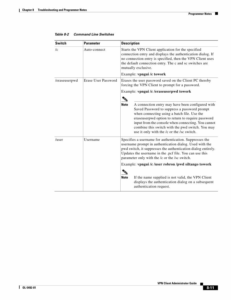
Chapter 8 Troubleshooting and Programmer Notes Programmer Notes
Table 8-2 Command Line Switches
Switch Parameter Description
/c Auto-connect Starts the VPN Client application for the specified connection entry and displays the authentication dialog. If no connection entry is specified, then the VPN Client uses the default connection entry. The c and sc switches are mutually exclusive.
Example: vpngui /c towork
/eraseuserpwd Erase User Password Erases the user password saved on the Client PC thereby forcing the VPN Client to prompt for a password.
Example: vpngui /c /eraseuserpwd towork
Note A connection entry may have been configured with Saved Password to suppress a password prompt when connecting using a batch file. Use the eraseuserpwd option to return to require password input from the console when connecting. You cannot combine this switch with the pwd switch. You may use it only with the /c or the /sc switch.
/user Username Specifies a username for authentication. Suppresses the username prompt in authentication dialog. Used with the pwd switch, it suppresses the authentication dialog entirely. Updates the username in the .pcf file. You can use this parameter only with the /c or the /sc switch.
Example: vpngui /c /user robron /pwd siltango towork
Note If the name supplied is not valid, the VPN Client displays the authentication dialog on a subsequent authentication request.
8-11VPN Client Administrator Guide
OL-5492-01

Chapter 8 Troubleshooting and Programmer Notes Programmer Notes
/pwd Password Specifies a password for authentication. Suppresses the password prompt in authentication dialog. Used with the pwd switch, it suppresses the authentication dialog entirely. Updates the password in the .pcf file during authentication and then clears the password from the .pcf file. You can use this switch only with the /c or the /sc switch.
Example: vpngui /c /user robron /pwd siltango towork
Note If the password supplied is not valid, the VPN Client displays the authentication dialog on a subsequent authentication request. After encrypting and using the password for the connection, the VPN Client clears the password in the .pcf file. Using this option on the command line compromises security and is not recommended.
/sd Silent disconnect Suppresses connection terminating messages, such as “Your IPSec connection has been terminated.” You can use this parameter to improve the automatic connection process. You can use this switch only with the /c or the /sc switch.
Example: vpngui /sd towork
Table 8-2 Command Line Switches (continued)
Switch Parameter Description
8-12VPN Client Administrator Guide
OL-5492-01

Chapter 8 Troubleshooting and Programmer Notes IKE Proposals
IKE ProposalsTable 8-3 lists the IKE proposals that the VPN Client supports.
Table 8-3 Valid VPN Client IKE Proposals
Proposal NameAuthentication Mode
Authentication Algorithm
Encryption Algorithm
Diffie- HellmanGroup
CiscoVPNClient-3DES-MD5 Preshared Keys (XAUTH)
MD5/HMAC-128 3DES-168 Group 2(1024 bits)
CiscoVPNClient-3DES-SHA Preshared Keys (XAUTH)
SHA/HMAC-160 3DES-168 Group 2(1024 bits)
CiscoVPNClient-DES-MD5 Preshared Keys (XAUTH)
MD5/HMAC-128 DES-56 Group 2(1024 bits)
CiscoVPNClient-AES128-MD5 Preshared Keys (XAUTH)
MD5/HMAC-128 AES-128 Group 2(1024 bits)
CiscoVPNClient-AES128-SHA Preshared Keys (XAUTH)
SHA/HMAC-160 AES-128 Group 2(1024 bits)
CiscoVPNClient-AES256-MD5 Preshared Keys (XAUTH)
MD5/HMAC-128 AES-256 Group 2(1024 bits)
CiscoVPNClient-AES256-SHA Preshared Keys (XAUTH)
SHA/HMAC-160 AES-256 Group 2(1024 bits)
IKE-3DES-MD5 Preshared Keys MD5/HMAC-128 3DES-168 Group 2(1024 bits)
IKE-3DES-SHA Preshared Keys SHA/HMAC-160 3DES-168 Group 2(1024 bits)
IKE-DES-MD5 Preshared Keys MD5/HMAC-128 DES-56 Group 2(1024 bits)
IKE-AES128-MD5 Preshared Keys MD5/HMAC-128 AES-128 Group 2(1024 bits)
IKE-AES128-SHA Preshared Keys SHA/HMAC-160 AES-128 Group 2(1024 bits)
IKE-AES256-MD5 Preshared Keys MD5/HMAC-128 AES-256 Group 2(1024 bits)
IKE-AES256-SHA Preshared Keys SHA/HMAC-160 AES-256 Group 2(1024 bits)
CiscoVPNClient-3DES-MD5-RSA RSA Digital Certificate (XAUTH)
MD5/HMAC-128 3DES-168 Group 2(1024 bits)
CiscoVPNClient-3DES-SHA-RSA RSA Digital Certificate (XAUTH)
SHA/HMAC-160 3DES-168 Group 2(1024 bits)
CiscoVPNClient-DES-MD5-RSA-DH1 RSA Digital Certificate (XAUTH)
MD5/HMAC-128 DES-56 Group 1 (768 bits)
CiscoVPNClient-AES128-MD5-RSA RSA Digital Certificate (XAUTH)
MD5/HMAC-128 AES-128 Group 2(1024 bits)
8-13VPN Client Administrator Guide
OL-5492-01

Chapter 8 Troubleshooting and Programmer Notes IKE Proposals
CiscoVPNClient-AES128-SHA-RSA RSA Digital Certificate (XAUTH)
SHA/HMAC-160 AES-128 Group 2(1024 bits)
CiscoVPNClient-AES256-MD5-RSA RSA Digital Certificate (XAUTH)
MD5/HMAC-128 AES-256 Group 2(1024 bits)
CiscoVPNClient-AES256-SHA-RSA RSA Digital Certificate (XAUTH)
SHA/HMAC-160 AES-256 Group 2(1024 bits)
CiscoVPNClient-3DES-MD5-RSA-DH5 RSA Digital Certificate (XAUTH)
MD5/HMAC-128 3DES-168 Group 5(1536 bits)
CiscoVPNClient-3DES-SHA-RSA-DH5 RSA Digital Certificate (XAUTH)
SHA/HMAC-160 3DES-168 Group 5 (1536 bits)
CiscoVPNClient-AES128-MD5-RSA-DH5 RSA Digital Certificate (XAUTH)
MD5/HMAC-128 AES-128 Group 5(1536 bits)
CiscoVPNClient-AES128-SHA-RSA-DH5 RSA Digital Certificate (XAUTH)
SHA/HMAC-160 AES-128 Group 5(1536 bits)
CiscoVPNClient-AES256-MD5-RSA-DH5 RSA Digital Certificate (XAUTH)
MD5/HMAC-128 AES-256 Group 5 (1536 bits)
CiscoVPNClient-AES256-SHA-RSA-DH5 RSA Digital Certificate (XAUTH)
SHA/HMAC-160 AES-256 Group 5(1536 bits)
CiscoVPNClient-3DES-MD5-RSA RSA Digital Certificate (XAUTH)
MD5/HMAC-128 3DES-168 Group 2(1024 bits)
HYBRID-3DES-SHA-RSA RSA Digital Certificate (HYBRID)
SHA/HMAC-160 3DES-168 Group 2(1024 bits)
HYBRID-DES-MD5-RSA-DH1 RSA Digital Certificate (HYBRID)
MD5/HMAC-128 DES-56 Group 1 (768 bits)
HYBRID-AES128-MD5-RSA RSA Digital Certificate (HYBRID)
MD5/HMAC-128 AES-128 Group 2(1024 bits)
HYBRID-AES128-SHA-RSA RSA Digital Certificate (HYBRID)
SHA/HMAC-160 AES-128 Group 2(1024 bits)
HYBRID-AES256-MD5-RSA RSA Digital Certificate (HYBRID)
MD5/HMAC-128 AES-256 Group 2(1024 bits)
HYBRID-AES256-SHA-RSA RSA Digital Certificate (HYBRID)
SHA/HMAC-160 AES-256 Group 2(1024 bits)
HYBRID-3DES-MD5-RSA-DH5 RSA Digital Certificate (HYBRID)
MD5/HMAC-128 3DES-168 Group 5(1536 bits)
HYBRID-3DES-SHA-RSA-DH5 RSA Digital Certificate (HYBRID)
SHA/HMAC-160 3DES-168 Group 5 (1536 bits)
HYBRID-AES128-MD5-RSA-DH5 RSA Digital Certificate (HYBRID)
MD5/HMAC-128 AES-128 Group 5(1536 bits)
HYBRID-AES128-SHA-RSA-DH5 RSA Digital Certificate (HYBRID)
SHA/HMAC-160 AES-128 Group 5(1536 bits)
HYBRID-AES256-MD5-RSA-DH5 RSA Digital Certificate (HYBRID)
MD5/HMAC-128 AES-256 Group 5 (1536 bits)
Proposal NameAuthentication Mode
Authentication Algorithm
Encryption Algorithm
Diffie- HellmanGroup
8-14VPN Client Administrator Guide
OL-5492-01

Chapter 8 Troubleshooting and Programmer Notes IKE Proposals
HYBRID-AES256-SHA-RSA-DH5 RSA Digital Certificate (HYBRID)
SHA/HMAC-160 AES-256 Group 5(1536 bits)
IKE-3DES-MD5-RSA RSA Digital Certificate MD5/HMAC-128 3DES-168 Group 2(1024 bits)
IKE-3DES-SHA-RSA RSA Digital Certificate SHA/HMAC-160 3DES-168 Group 2(1024 bits)
IKE-AES128-MD5-RSA RSA Digital Certificate MD5/HMAC-128 AES-128 Group 2(1024 bits)
IKE-AES128-SHA-RSA RSA Digital Certificate SHA/HMAC-160 AES-128 Group 2(1024 bits)
IKE-AES256-MD5-RSA RSA Digital Certificate MD5/HMAC-128 AES-256 Group 2(1024 bits)
IKE-AES256-SHA-RSA RSA Digital Certificate SHA/HMAC-160 AES-256 Group 2(1024 bits)
IKE-DES-MD5-RSA-DH1 RSA Digital Certificate MD5/HMAC-128 DES-56 Group 1 (768 bits)
IKE-3DES-MD5-RSA-DH5 RSA Digital Certificate MD5/HMAC-128 3DES-168 Group 5(1536 bits)
IKE-3DES-SHA-RSA-DH5 RSA Digital Certificate SHA/HMAC-160 3DES-168 Group 5 (1536 bits)
IKE-AES128-MD5-RSA-DH5 RSA Digital Certificate MD5/HMAC-128 AES-128 Group 5 (1536 bits)
IKE-AES128-SHA-RSA-DH5 RSA Digital Certificate SHA/HMAC-160 AES-128 Group 5(1536 bits)
IKE-AES256-MD5-RSA-DH5 RSA Digital Certificate MD5/HMAC-128 AES-256 Group 5 (1536 bits)
IKE-AES256-SHA-RSA-DH5 RSA Digital Certificate SHA/HMAC-160 AES-256 Group 5 (1536 bits)
Proposal NameAuthentication Mode
Authentication Algorithm
Encryption Algorithm
Diffie- HellmanGroup
8-15VPN Client Administrator Guide
OL-5492-01

Chapter 8 Troubleshooting and Programmer Notes Unit Client Application Program Interface
Table 8-4 lists phase 2 proposals that the VPN Client sends.
Unit Client Application Program InterfaceThe VPN Client software includes an API that customers can use to perform VPN Client tasks without using the standard command-line or graphical interfaces that Cisco provides. The API comprises a shared library that programmers can link into their application, which allows it to:
• Connect and disconnect VPN tunnels
• Authenticate users
• Receive notifications when tunnels open and close
• Retrieve tunnel statistics, such as byte and packet counts
The API comes with a programmer’s user guide VPN Client: API Overview. This guide contains information enabling a programmer not familiar with the code base to use the API. The programmer’s guide describes functions and data types, an overview of how to accomplish specific tasks, and easy to follow example programs.
Table 8-4 Phase 2 Proposals
AES256 MD5 IPCOMPRESSION
AES256 SHA IPCOMPRESSION
AES128 MD5 IPCOMPRESSION
AES128 SHA IPCOMPRESSION
AES256 MD5
AES256 SHA
AES128 MD5
AES128 SHA
3DES MD5 IPCOMPRESSION
3DES SHA IPCOMPRESSION
3DES MD5
3DES SHA
DES MD5 IPCOMPRESSION
DES MD5
NULL MD5
NULL SHA
8-16VPN Client Administrator Guide
OL-5492-01

OL-5492-01
C H A P T E R 9
Windows Installer (MSI) InformationThis chapter describes how to use the Microsoft Windows Installer for the network administrator. For end user instructions, see Cisco VPN Client for Windows User Guide, Chapter 2. For information on customizing the VPN Client applications, see “Customizing the VPN Client Using an MSI Transform.” For installing MSI without user interaction, see “Installing the VPN Client Without User Interaction.”
This chapter includes the following main topics:
Differences Between InstallShield and MSI
Starting the VPN Client MSI
Logging During Installation
Differences Between InstallShield and MSITable 9-1 describes the differences between InstallShield and MSI installation.
Table 9-1 InstallShield and MSI Features Compared
InstallShield MSI
Supported on all platforms including Windows 9.x
Supported only on Windows NT SP6, Windows 2000, and Windows XP.
Detects and uninstalls an older VPN Client. Detects but does not automatically uninstall an older VPN Client. Remove previous versions via Add/Remove programs.
Provides a proprietary installation package and customizing process.
Provides a standard installation package and customizing process.
Silent installation suppresses all dialogs and messages, including errors.
Silent installation can be customized to include error reporting.
Provides no automatic rollback when installation fails.
Provides automatic rollback in case of installation failure; undoes changes to the system made during attempted installation.
No automatic replacement of deleted or corrupted files upon first use
Automatic replacement of deleted or corrupted files upon first use. Replaces registry keys associated with shortcuts under Start | Program Files.
9-1VPN Client Administrator Guide

Chapter 9 Windows Installer (MSI) Information Starting the VPN Client MSI
Starting the VPN Client MSIInstalling the VPN Client 4.0 via MSI requires Windows Installer version 2.0, which is standard with Windows XP but not with Windows NT 4.0 (SP6) or Windows 2000. When using MSI to install the VPN Client on Windows NT and Windows 2000, the installation application installs or upgrades Windows Installer to version 2.0. This occurs only once.
To install the VPN Client, you must be an administrator or a restricted user with elevated privileges. However, for the restricted user with elevated privileges, the installation program adds the VPN Client to the Program Menu for only the user that installed the VPN Client, not for all users.
Alternative Ways to Launch MSI There are various ways to launch MSI. Cisco VPN Client User Guide for Windows explains how to install the VPN Client using an executable that runs a wizard (vpnclient_en.exe). This method automatically installs or upgrades the Windows Installer to version 2.0 if necessary. However, this is only one way to install the application.
Launching MSI via Command Line
If Windows Installer 2.0 is already installed, you can install the VPN Client using the msiexec.exe command on the command line as follows.
msiexec.exe /i vpnclient_en.msi [options]
where
/i is the installation switch.
vpnclient_en.msi is the application to be installed.
Note For complete documentation on the msiexec.exe command, see Windows Installer version 2.0, Microsoft Platform SDK, August 2001.
Launching MSI via the MSI Icon
If Windows Installer is already installed, you can launch the installation package by double-clicking the MSI icon.
Figure 9-1 MSI icon
9-2VPN Client Administrator Guide
OL-5492-01

Chapter 9 Windows Installer (MSI) Information Logging During Installation
Logging During InstallationTo better understand what is happening while MSI is installing the VPN Client, you should initiate logging on the command line by executing the msiexec.exe command with the following options:
msiexec.exe /l [i|w|e|a|r|u|c|m|o|p|v|+|!|*] logfile
where:
/l is the switch that turns on logging.
logfile is the name of the file to receive the logging information.
Example 9-1 Installing with Logging
The following command installs the VPN Client and includes a log of all information (*v). It also specifies sending each line to the log file (!).
msiexec /i vpnclient_en.msi /l*v! vpnclient_msi.log
Example 9-2 Installing via the Executable from the Command Line with Logging
The following command installs the VPN Client and logs all information to a log file.
vpnclient_en.exe /l*v! vpnclient_msi.log
Note You should always include the ! option for logging, since many of the installer events are not recorded if you do not include this option.
Option Information Provided
i Status messages
w Non-fatal warnings
e All error messages
a Start up actions
r Action-specific records
u User requests
c Initial user interface parameters
m Out-of-memory or fatal exit information
o Out-of-disk-space messages
p Terminal properties
v Verbose output
+ Append to existing file
! Send each line to the log
* Log all information except for what the verbose option generates.
9-3VPN Client Administrator Guide
OL-5492-01

Chapter 9 Windows Installer (MSI) Information Logging During Installation
9-4VPN Client Administrator Guide
OL-5492-01

OL-5492-01
I N D E X
A
activating an IKE proposal 1-4
adding an SA 1-4
AppendOriginalSuffix Option parameter 2-16
ApplicationLauncher parameters 2-10
authentication
mutual group
authentication types 1-20
types 2-20
authentication parameters (.pcf file) 2-21
AuthType parameter (.pcf file) 2-20
auto initiation 4-5
AutoInitiationEnable (vpnclient.ini) 2-6, 4-3
AutoInitiationList (vpnclient.ini) 2-7, 4-3
AutoInitiationRetryInterval (vpnclient.ini) 2-6, 4-3
AutoInitiationRetry IntervalType (vpnclient.ini) 2-7
AutoInitiationRetryIntervalType (vpnclient.ini) 4-3
AutoInitiationRetry Limit (vpnclient.ini) 2-7
configuring 4-1
connect parameter 4-3
creating in vpnclient.ini file 4-3
examples 4-4
excluding networks from 4-3
parameters 4-1
automatic browser configuration
configuring on VPN Concentrator 1-17
autoupdating VPN Client software
creating configuration file 3-6
creating profile distribution package 3-7
enabling on VPN Concentrator 3-3
how it works 3-8
managing 3-3
Windows 2000 and Windows XP 3-2
AYT firewall policy 1-7
B
BackupServer parameter (.pcf file) 2-22
backup servers
configured on VPN Concentrator for VPN Client 1-16
Baltimore Technologies 1-5
bitmaps
setup.bmp 7-2, 7-5
BlackIce Defender
firewall on remote PC 1-7
bmp files
for installation 7-2
setup 7-5
branding software
see customizing VPN Client software
brand parameters (oem.ini file) 7-6
browser proxy configuration 1-17
bypassing DHCP server 2-8
C
Centralized Protection Policy (CPP) 1-6
certificate
connecting 1-5
contents 6-2
enrolling a CA 6-6
enrollment 6-2
PKI 1-5
example 6-3
IN-1VPN Client Administrator Guide

Index
management 6-1
management operations 6-4
passwords 6-3
root 6-2
store 6-1
tags 6-4
user 6-1
Certificate Authorities (CA)
supported 1-5
certificates
enrollment
IP address 2-9
parameters (vpnclient.ini) 2-9
Entrust 1-18
group name requirement 1-4
organization unit field 1-4
parameters (.pcf files) 2-24
VPN Client connections
configuring VPN concentrator 1-3
change password operation 6-6
changing method of initializing VA 2-7
changing the MTU size 8-5
Cisco Integrated Client
scenario 1-8
VPN Client software 1-6
Cisco Security Agent
firewall on the remote PC 1-7
client/server firewall 1-7
client update on VPN Concentrator 3-3
command-line interface
error messages 5-11
minimum argument 6-1
command-line switches
vpngui 8-10
commands
msiexec 7-15, 9-2
logging options 9-3
IN-2VPN Client Administrator Guide
vpnclient
connect 5-2
disconnect 5-6
displaying a list 5-1
notify 5-4
stat 5-6
verify autoinitconfig 5-5
vpngui
command-line switches 8-10
company logo
logo.png 7-9
configuration parameters
global profile 2-3
individual profiles 2-20
configurations
client/server 1-11
configuring
auto initiation 4-1
backup servers for VPN Client 1-16
browser proxy 1-17
Entrust certificate 1-18
local LAN access for VPN Client 1-14
NAT-T 1-16
personal firewalls 1-5
RADIUS SDI authentication 2-16
connected.png
lock image on active connection entry 7-9
connecting from command line
vpngui command 8-10
connection
ending 5-6
getting status 5-6
profiles 2-17
starting with vpnclient command 5-2
testing 8-9
connection entry
default 2-13
features controlled 2-17
file 2-18
OL-5492-01

Index
preconfigured
distributing 2-26
sample .pcf file 2-17
connection-specific DNS suffix 2-14
connect on open
activating 2-13
ConnectOnOpen (vpnclient.ini) 2-7
continuous display (stat command) 5-7
CPP
defining filters and rules 1-10
creating 7-10
connection profiles 2-17
Entrust profile 1-18
global profile 2-2
IPSec group in VPN Concentrator 1-2
MSI transform 7-10
oem.ini file 7-5
user profiles in VPN Concentrator 1-3
customizing VPN Client software
areas affected by 7-2
for MSI 7-10
menu titles and text 7-3
oem.ini file 7-5
setup bitmap 7-2
VPN Dialer application 7-4
D
data formats xii
default connection entry
connect on open 2-7
default user profile 2-13
DefGroup parameter (oem.ini file) 7-7
defining rules for firewalls 1-10
delete operation 6-5
Description parameter (.pfc file) 2-20
DHCP inbound traffic
stateful firewall 1-6
OL-5492-01
DHCP server
bypassing 2-8
DHGroup parameter (.pcf files) 2-25
DialerDisconnect parameter (vpnclient.ini) 2-6
dialer parameters (oem.ini file) 7-7
differences between InstallShield and MSI 9-1
directory
profiles 2-2, 2-17
Disable Fast Shutdown option 8-5
DisableKerberosOverTCP (oem.ini file) 7-6
displaying
information continuously 5-7
notifications 5-4
route information 5-7
distributing new profiles 3-7
distributing preconfigured software 2-26
DNS parameters 2-10
DNS suffix
connection-specific 2-14
primary 2-14
Windows platforms 2-13
documentation
additional x
cautions xii
notes xii
E
elevated privileges (installing MSI) 9-2
EnableBackup parameter (.pcf file) 2-22
EnableISPConnect parameter (.pcf file) 2-21
EnableLocalLAN parameter (.pcf file) 2-23
EnableLog parameter (vpnclient.ini) 2-6
EnableNat parameter (.pcf file) 2-23
EnableSplitDNS parameter (.pfc file) 2-25
encGroupPwd parameter (.pcf file) 2-21
ending a connection 5-6
enroll file operation 6-5
IN-3VPN Client Administrator Guide

Index
enrolling
in a PKI 1-5
enrolling a CA for certificates 6-2, 6-6
enrollment keywords 6-7
enroll operation 6-5
enroll resume operation 6-6
Entrust
Technologies 1-5
Entrust certificates
enabling VPN Client 1-18
EntrustIni parameter (vpnclient.ini) 2-5
error messages 5-11
errors
reporting
faultlog.txt file 8-2
ESP inbound traffic
stateful firewall 1-6
events
severity 1
faultlog.txt file 8-2
excluding networks from auto initiation 4-3
export operation 6-5
F
fallback mode 8-9
faultlog.txt file 8-2
files
.bmp 7-2
.pcf 2-17
.png 7-8
oem.ini 7-5
vpnclient.ini 2-2
sample 2-3
filters
defining for CPP 1-10
firewall information 5-7
IN-4VPN Client Administrator Guide
firewalls
AYT 1-7
BlackIce Defender 1-7
Cisco Integrated Client 1-6
Cisco Security Agent 1-7
client/server
configuring 1-11
configurations
group 1-11
matching 1-6
scenarios 1-8
CPP 1-6
custom 1-12
defining filters and rules 1-10
Integrity Server 1-7
notifications during negotiations 1-13
personal firewall
enforcement on remote PC 1-7
requiring 1-6
stateful on VPN Client 1-6
Sygate Personal Firewall 1-7
Sygate Personal Firewall Pro 1-7
Sygate Security Agent 1-7
Zone Alarm Firewall 1-7
Zone Alarm Pro Firewall 1-7
ForceNetlogin parameter (.pfc file) 2-26
formats
data xii
FQDN (fully qualified domain name) 6-2
fragmentation
preventing 8-5
G
global profile
creating 2-2
GroupName parameter (.pcf file) 2-20
GroupPwd parameter (.pcf file) 2-20
GUI parameters 2-12
OL-5492-01

Index
H
hash 6-2
HKEY_LOCAL_MACHINE 8-9
Host parameter (.pcf file) 2-20
I
icons
connected.ico 7-10
disconnecting.ico 7-10
lock 7-4
unconnected.ico 7-10
IKE proposals
activating 1-4
list 8-13
phase 2 8-16
images
lock 7-4
import operation 6-5
incompatible ginas
adding 8-9
fallback mode 8-9
start before logon feature 8-8
IncompatibleGinas parameter (vpnclient.ini file) 2-5
initializing VA
changing method 2-7
Installation
MSI requirements 9-2
installation
automatic 7-1
differences between MSI and Installshield 9-1
installer
directory 7-18
package 7-18
installing
MSI transform 7-15
InstallPath parameter (oem.ini file) 7-7
OL-5492-01
InstallShield
installation differences from MSI 9-1
setup.bmp file 7-2
silent install 7-16
Integrity Server firewall
configuring 1-11
feature description 1-7
IP addresses
certificate enrollment 2-9
IPSec group
creating on VPN Concentrator 1-2
IPSec log file
troubleshooting firewall configurations 1-12
ISPCommand parameter (.pcf file) 2-21
ISPConnect parameter (.pcf file) 2-21
ISPConnectType parameter (.pcf file) 2-21
K
key size 6-2
keywords for enrollment operations 6-7
L
Legacy IKE Port
changing 2-26
list operation 6-4
LMHOSTS file 1-16
local LAN access
configuring 1-14
lock image
in title lines 7-4
next to active connection entry 7-9
logging during MSI installation 9-3
LogLevel parameter 2-8
logo.png 7-9
log parameters (vpnclient.ini) 2-8
IN-5VPN Client Administrator Guide

Index
M
making a parameter read only 2-2
managing
autoupdates 3-3
matching firewall configurations 1-6
maximum transmission unit
see MTU setting
Microsoft
Certificate Services 1-5
Windows 2000 1-5
MissingGroupDialog parameter (vpnclient.ini) 2-5
MSI
installation differences from InstallShield 9-1
launching 9-2
logging during installation 9-3
silent install 7-17
msiexec command 7-15
MSI transform
customizing VPN Client 7-10
installing 7-15
MSLogonType parameter (.pcf file) 2-22, 2-23
MTU setting
affects of 8-5
changing 8-5
mutual authentication 2-20
mutual group authentication 1-20
N
NAT Transparency (NAT-T)
configuring on VPN Concentrator 1-16
Net login
forcing 2-26
Netlogin parameters 2-11
new/modify profile dialog
profile_logo.png 7-9
new_update_config.ini file
parameters (table) 3-6
IN-6VPN Client Administrator Guide
new connection entries
distributing 3-7
notifications
displaying 5-4
firewalls 1-13
upgrade 1-13, 3-1
notify command 5-4
NTDomain parameter (.pfc file) 2-22
O
oem.ini file
creating 7-5
customizing VPN Client 7-5
keywords and values 7-6
MSI equivalents 7-14
sample 7-5
operations for certificate management 6-4
Organization 7-9
organizational unit field in certificate 1-4
organization logo
logo.png file 7-9
P
parameters
brand (oem.ini file) 7-6
DefGroup (oem.ini file) 7-7
dialer (oem.ini file) 7-7
DisableKerberosOverTCP (oem.ini file) 7-6
global
table 2-5
InstallPath (oem.ini file) 7-7
peer timeout (.pcf file) 2-23
profile (.pcf)
authentication 2-21
AuthType 2-20
BackupServer 2-22
OL-5492-01

Index
certificate parameters 2-24
Description 2-20
DHGroup 2-25
EnableISPConnect 2-21
EnableLocalLAN 2-23
EnableMSLogon 2-22
EnableNat 2-23
EnableSplitDNS 2-25
encGroupPwd 2-21
ForceNetlogin 2-26
GroupName 2-20
GroupPwd 2-20
Host 2-20
ISPCommand 2-21
ISPConnect 2-21
ISPConnectType 2-21
MSLogonType 2-22, 2-23
NTDomain 2-22
PeerTimeout 2-23
RadiusSDI 2-25
SaveUserPassword 2-22
SDIUseHardwareToken 2-25
SendCertChain 2-24
TCPTunnelingPort 2-23
TunnelingMode 2-23
UseLegacyIKEPort 2-26
VerifyCertDN 2-25
read only 2-2
reboot (oem.ini file) 7-7
Set Mtu (oem.ini file) 7-7
SilentMode (oem.ini file) 7-7
vpnclient.ini
AppendOriginalSuffixOption 2-16
ApplicationLauncher 2-10
AutoInitiationEnable 2-6
AutoInitiationList 2-7
AutoInitiationRetry 2-6
AutoInitiationRetrylLimit 2-7
AutoInitiationRetryType 2-7
OL-5492-01
certificate enrollment 2-9
ConnectOnOpen
configuring 2-7DialerDisconnect 2-6
DNS 2-10
EnableLog 2-6
EntrustIni 2-5
GUI 2-12
IncompatibleGinas 2-5
log class 2-8
LogLevel 2-8
MissingGroupDialog 2-5
Netlogin 2-11
RADIUS SDI 2-10
RunAtLogon 2-5
StatefulFirewall 2-6
StatefulFirewallAllowICMP 2-6
table 2-5
vpnclient command 5-7
vpnclient stat command
firewall 5-7
repeat 5-7
reset 5-7
route 5-7
traffic 5-7
tunneling 5-7
password_logo.png
Xauth dialog 7-9
pcf files
creating 2-17
distributing with VPN Client software 2-27
parameters 2-20
sample 2-18
PeerTimeout parameter (.pcf file) 2-23
personal firewalls
configuring for VPN Client
VPN Concentrator 1-5
phase 2 IKE proposals 8-16
IN-7VPN Client Administrator Guide

Index
PKIs
supported 1-5
Portable Network Graphic (PNG) files
list 7-8
preconfigured connection entry
distributing 2-26
preconfigured files 7-18
preconfiguring VPN Clients for remote users 2-1
pre-shared key authentication
certificate authentication 2-20
primary DNS suffix 2-14
printing by name on local LAN 1-16
profile
connection entry 2-17
creating user 1-3
directory 2-2
Entrust 1-18
file format 2-2
global 2-2
features controlled 2-2
parameters 2-4
sample 2-3
profile_logo.png
new/modify profile dialog 7-9
profiles
distributing 3-7
programmer notes
testing a connection 8-9
proposals
IKE 1-4, 8-13
phase 2 IKE 8-16
Public Key Infrastructure
see PKIs
R
RADIUS SDI authentication
configuring 2-16
RadiusSDI parameter (.pfc file) 2-25
IN-8VPN Client Administrator Guide
RADIUS SDI parameters 2-10
read-only parameters 2-2
Reboot parameter (oem.ini) file) 7-7
registry
testing a connection 8-9
related documentation xi
Remote Firewall
scenario 1-8
resetting counts 5-7
root certificates 6-2
routing information 5-7
rules
defining for CPP 1-10
RunAtLogon parameter (vpnclient.ini) 2-5
S
SA
adding 1-4
sample files
.pcf file 2-18
oem.ini file 7-5
vpnclient.ini 2-3
SaveUserPassword parameter (.pfc file) 2-22
SDIUseHardwareToken parameter (.pfc file) 2-25
SendCertChain parameter 2-24
Set Mtu parameters 7-7
SetMTU utility 8-5
launching silently 7-17
setup.bmp 7-2, 7-5
silent install 7-1
InstallShield 7-16
MSI 7-17
SilentMode parameter (oem.ini file) 7-7
splash screen
splash_screen.png
splash_screen.png 7-9
Split DNS
enabling 2-25
OL-5492-01

Index
start before logon
gina files 8-8
starting a connection 5-2
stateful firewall (always on) 1-6
StatefulFirewallAllowICMP parameter (vpnclient.ini) 2-6
StatefulFirewall parameter (vpnclient.ini) 2-6
status information
generating 5-6
Sygate Personal Firewall
firewall on remote PC 1-7
Sygate Personal Firewall Pro
firewall on remote PC 1-7
Sygate Security Agent
firewall on remote PC 1-7
system information
Windows 98 8-1
Windows NT 8-3
system security
protecting 2-19
T
TCPTunnelingPort parameter (.pcf file) 2-23
testing a connection 8-9
traffic information 5-7
transform 7-10
installing 7-15
troubleshooting
connectivity application 8-5
generating information 8-1
TunnelEstablished parameter in registry 8-9
tunneling information 5-7
TunnelingMode parameter (.pcf file) 2-23
U
UniCERT 1-5
update files (Table) 3-5
OL-5492-01
updating VPN Client software
all client types 3-1
automatically (Windows 2000 and Windows XP) 3-2
Linux 3-2
MAC OS X 3-2
Solaris 3-2
upgrade notifications
configured on VPN Concentrator 1-13, 3-1
UseLegacyIKEPort parameter (.pfc file) 2-26
user certificates 6-1
user profiles
certificate
keywords 6-1
creating for distribution 2-17
creating in VPN Concentrator 1-3
location 2-2, 2-17
V
VAenableAlt 2-7
VerifyCertDN parameter (.pfc file) 2-25
verifying an auto initiation configuration 4-5, 5-5
verify operation 6-5
view operation 6-4
virtual adapter
method of initializing 2-7
VPN Client
applications ix
configuring 2-1
vpnclient.ini file
file format 2-2
sample 2-3
vpnclient_en.msi command 9-2
vpnclient commands
disconnect 5-6
displaying a list 5-1
notify 5-4
IN-9VPN Client Administrator Guide

Index
stat 5-6
firewall 5-7
repeat 5-7
reset 5-7
route 5-7
traffic 5-7
tunnel 5-7
verify autoinitconfig 5-5
VPN Concentrator
configuring personal firewalls for VPN Client 1-5
creating user profiles 1-3
VPN Dialer
customizing 7-4
W
Windows 98
generating system information 8-3
shut down problem 8-5
Windows NT or Windows 2000
generating system information 8-3
WINMSD utility
Windows NT or Windows 2000 8-3
X
Xauth dialog
password_logo.png 7-9
Z
Zone Alarm Firewall
firewall on remote PC 1-7
Zone Alarm Pro Firewall
firewall on remote PC 1-7
IN-10VPN Client Administrator Guide
OL-5492-01