vowlan design recommendations - · pdf file† handset antenna characteristics ......
TRANSCRIPT

C H A P T E R 9
VoWLAN Design RecommendationsThis chapter provides additional design considerations for deploying voice over WLAN (VoWLAN) solutions. WLAN configuration specifics can vary depending on the VoWLAN device being used and the WLAN design. This chapter provides details about key RF and site survey considerations that are generally applicable to VoWLAN deployments, which were introduced in .Chapter 3, “WLAN RF Design Considerations”
Softphone applications are key VoWLAN solutions and they are available on a number of hardware and operating systems platforms. The Cisco JabberTM, application lets you access presence, instant messaging (IM), audio, video, voice messaging, desktop sharing, and conferencing. Jabber downloads for smartphones, tablets, and laptops along with information on design guides for each of the variants can be referred at Cisco Jabber.
Antenna ConsiderationsThe more demanding network requirements of VoWLAN impacts WLAN planning at all levels, including the choice of antenna. Key antenna considerations are as follows:
• Access point (AP) antenna selection
• Antenna placement
• Handset antenna characteristics
AP Antenna SelectionCisco recommends a ceiling-mounted antenna solution for VoWLAN applications. Ceiling mounted antennas and APs with internal antennas are quick and easy to install. More importantly, they place the radiating portion of the antenna in open space, which allows the most efficient signal propagation and reception. Cisco APs with internal antennas offer the easiest installation solution, plus the internal antennas provide a downward signal propagation pattern that is well suited for the majority of installations. The internal antenna solution is particularly well suited to the open spaces of enterprise environments.
Cisco offers a variety of multiple-input and multiple-output (MIMO) dual band, dual radiating element Omni-directional and Directional (patch style) antennas. These multiple element antennas are designed to take advantage of IEEE 802.11n and .11ac technologies such as Maximum Ratio Combining (MRC) and unique Cisco performance features such as ClientLink. These technologies combine client phone packets, (as they are captured on the multiple antennas of the APs) into a single, combined signal that is stronger. The combined signal provides a better signal-to-noise ratio (SNR) between the phone's
9-1Enterprise Mobility 8.1 Design Guide

Chapter 9 VoWLAN Design RecommendationsAntenna Considerations
transmitted packet and the general 2.4 or 5 GHz band noise. An important feature of MRC is that it reduces the upstream packet error rate. Cisco APs use the multiple antennas and 802.11 ClientLink logic to deliver a higher energy packet to the client phone, which reduces the downstream packet error rate. These two features improve the mean opinion score (MOS) value of individual VoWLAN calls and the overall capacity of the Wi-Fi channel of the APs.
Cisco recommends that all antennas be placed 1 to 2 wavelengths away from highly reflective surfaces such as metal. The length of the 2.4 GHz waves is 4.92 inches (12.5 cm), and the length of the 5 GHz waves is 2.36 inches (6 cm). The separation of one or more wavelengths between the antenna and reflective surfaces allows the AP radio a better opportunity to receive a transmission and reduces the creation of nulls when the radio transmits. Orthogonal frequency-division multiplexing (OFDM), used by the 802.11g/n and 802.11a/n/ac specifications, helps to mitigate problems with reflections, nulls, and multipath. However, good antenna placement and the use of the appropriate antenna types provide a superior solution. The ceiling tile itself is a good absorber of signals transmitted into the area above the ceiling and reflected back into the coverage area.
For information on MRC, see the IEEE Report.
For more information on ClientLink, refer the following:
• Cisco Wireless ClientLink 3.0 Technology
• Cisco Aironet 3700 Series White Paper
Antennas come in a variety of types and form factors; no single type is best for all applications and locations. For additional information on the performance and part numbers of various antenna types, see the Cisco Aironet Antennas and Accessories Reference Guide.
Cisco recommends using the Cisco Aironet dipole dual band AIR-ANT2524D series antenna when attaching dipole antennas to an AP with dual (2.4 GHz and 5 GHz) band support from the same external antenna port.
The Aironet dipole dual band antennas provide the advantages of:
• Support for simultaneous 2.4 and 5 GHz dual band transmission and reception (the same as the dual band omni and patch antennas). The gain on the Aironet dipole dual band antennas is 2.2 dBi for the 2.4 GHz band and 4 dBi for the 5 GHz band.
• Being small and coming in neutral colors of black, grey and white.
• Having an articulating and rotating base.
Antenna OrientationCisco recommends that, for APs with multiple antennas, all the antennas be oriented in the same direction.
Note While APs are often depicted in marketing material showing the antennas arranged in multiple directions, as shown in Figure 9-1, Cisco does not recommended this practice.
9-2Enterprise Mobility 8.1 Design Guide

Chapter 9 VoWLAN Design RecommendationsAntenna Considerations
Figure 9-1 AP With Antennas Arranged (incorrectly) in Different Directions
The best MRC and ClientLink performance is obtained when all antennas of an AP are arranged in the same orientation, as shown in Figure 9-2.
Figure 9-2 AP With Antennas Arranged (correctly) in Same Orientation
Having all four antennas of the AP in a flat, straight out position increases the overall throughput of the coverage cell by 2 Mbps when using single spatial stream 802.11n smartphones.
9-3Enterprise Mobility 8.1 Design Guide

Chapter 9 VoWLAN Design RecommendationsAntenna Considerations
General RecommendationsCisco recommends for optimum Wi-Fi coverage cell bandwidth and client application performance (for dipole antenna types of all forms) that:
• Each AP antenna port be populated with an antenna.
• Each port must have the same antenna model.
• Each antenna has the same orientation.
The APs and the protocols they operate with are designed around MRC and ClientLink. Use an antenna system that follows these recommendations to capitalize on that technology and your AP hardware investment.
Higher gain antennas may spread the signal further on the horizontal plane, which creates a larger cell that could also pick up additional noise. This results in a lower SNR that increases the packet error ratio. SNR is defined by the following criteria:
• Signal—The radiated energy transmitted from one radio that can be received uninterrupted by another radio. For Wi-Fi this means that the transmitting radio is sending 802.11 protocol packets that the receiving radio is able to decode.
• Noise—Transmitted energy in the frequency range of the receiving radio that cannot be decoded by that radio.
The larger the difference in energy between the protocol packet and the background noise, the better the reception of the protocol packet and the lower the packet error rate and bit error rate. Coverage area design involves using channels to create the lowest possible packet error rate while maintaining a high audio call capacity.
Higher gain antennas can also reduce the number of calls on a Wi-Fi channel because of the increased coverage area. For audio, a ceiling-mounted antenna is preferred over a wall-mounted patch because the human head and body attenuate 5 dB of the signal (see Figure 9-3). Ceiling mounted antennas are better positioned to avoid more of this head and body attenuation than most wall-mounted antennas.
9-4Enterprise Mobility 8.1 Design Guide

Chapter 9 VoWLAN Design RecommendationsAntenna Considerations
Figure 9-3 Head and Hand Attenuation
Antenna PositioningCeiling-mounted antennas typically have better signal paths to handheld phones. The recommended coverage cell size takes into consideration the signal loss because of the attenuation of human heads and other obstacles. It is important to understand that the gain of antennas is reciprocal; gain applies equally to reception and transmission. Antenna gain is not an increase in transmitted power because the radio produces the transmitted power. The antenna is only a passive device. Gain is derived by focusing the signal of the radio into a direction, plane, and beam width, much in the same way a flashlight reflector focuses the light emanating from its bulb.
For further information on WLAN RF planning, see Chapter 3, “WLAN RF Design Considerations”.
Handset AntennasFor phones that integrate the antenna inside the body of the phone, the way the user holds the phone in their hand can influence signal attenuation by 4 dB. In some cases, a phone held against the head with the hand covering the antenna can result in a signal drop of 9 dB. The general rule for indoor deployments is that every 9 dB of signal loss reduces the coverage area in half. Figure 9-3 shows an example of the difference in radiating power from a handset when held to the head.
The typical smartphone and tablet computer have a Wi-Fi antenna system with negative dB gain. The typical smartphone antenna is -3 or -4 dBi. The typical laptop has a positive gain from 0 to 2 dBi. This difference in antenna gain reflects in a difference in coverage range between smartphones, tablets and laptops at the same AP. For a smartphone or tablet to obtain the best application performance, the AP channel coverage should be designed to the Wi-Fi capabilities of the smartphones or tablets themselves.
9-5Enterprise Mobility 8.1 Design Guide

Chapter 9 VoWLAN Design RecommendationsChannel Utilization
To provide optimum link quality between the smartphone, tablet or laptop and the AP, the AP should operate with ClientLink enabled. ClientLink is enabled by default with the Cisco wireless LAN controller (WLC).
Channel UtilizationThe 802.11, 802.11b, 802.11g and 802.11n protocol specifications use the same 2.4 GHz band and therefore they must be able to interoperate with each other. This interoperability introduces additional 802.11 protection protocol logic overhead that reduces channel throughput. Many sites already have devices using the Wi-Fi frequencies of the 2.4 GHz band, but there are a number of foreign devices that can use these same frequencies. These foreign devices include Bluetooth, cordless phones, video game controllers, surveillance cameras, and even microwave ovens. Because the 2.4 GHz band is so crowded, and coupled with constraints on its channel allocation, Cisco recommends using the 5 GHz Wi-Fi band for new VoWLAN deployments. The channels available in the 5 GHz band are generally not as heavily used at most sites (see Figure 9-4). It is important to note that use of the 5 GHz UNII-2 channels for VoWLAN traffic requires the absence of radar. Cisco therefore recommends that there should be additional testing at any new site to determine whether a particular UNII-2 channel should be configured to be blocked. The reason is that if an AP detects radar on a channel during normal use, it must leave that channel until the radar signal is no longer present.
Figure 9-4 Channel Utilization for 2.4 GHz Reporting
Before the installation of a Cisco Unified Wireless Network, the site can be tested for channel interference and utilization with tools from AirMagnet, Wild Packets, Cognio, and others. To aid in the design process, the AP On-Demand Statistics Display report generated by the Cisco Prime Infrastructure provides a spectrum review of:
• Client count versus RSSI
• Client count versus SNR
• Channel utilization
9-6Enterprise Mobility 8.1 Design Guide

Chapter 9 VoWLAN Design RecommendationsChannel Utilization
The ALOHAnet protocol defines a radio channel as full when channel utilization reaches 33 percent. This means the channel is busy enough that packets must wait for an open time slot before they are transmitted. The 46 percent channel utilization, as shown in Figure 9-4, is above the channel utilization wireless packetized Aloha standard.
To reduce channel utilization in the 2.4 GHz band, Cisco recommends moving clients to 5 GHz and removing the legacy 1 Mbps and 2 Mbps data rates from the 2.4 GHz configuration when legacy devices are not part of the client makeup.
Dynamic Frequency Selection and 802.11h Requirements of the APsThe Federal Communications Commission (FCC) of the United States, the European Telecommunications Standards Institute (ETSI), and other regulatory agencies have their own requirements regarding the use of radio frequencies. Portions of the 5 GHz band have been and are currently being used for such things as weather radars. Although most 5 GHz radar systems generally use higher frequencies with shorter wavelengths, there are still systems in place that overlap with some Wi-Fi frequencies in the 5 GHz UNII-2 bands. In 2006, the FCC opened the frequencies in the 5.470 to 5.725 MHz range to unlicensed use. With these additional frequencies came a requirement to maintain an interference-free AP configuration. The AP must constantly monitor for radar pulses (typically from military, satellite, or weather stations) and use dynamic frequency selection (DFS) to automatically switch to a clean channel if radar is detected.
When radar is detected, the system must carry out the following:
• Stop packet transmission within 200 ms
• Stop control transmissions within 10 seconds
• Avoid transmission on the channel for 30 minutes
• Scan a new channel for 60 seconds before transmission
Because the radar avoidance requirements in the UNII-2 band can impact audio call quality, you should conduct a test for radar before going live with audio applications. Cisco Spectrum Expert is an excellent tool to test for the presence of radar on certain channels. If radar is detected during a Spectrum Expert test, the APs can then be configured to block use of those channels.
5 GHz Band ChannelsThe DFS requirement includes the four original UNII-2 channels (52-64) and the new eight channels (100-116 and 132-140), while the 5 GHz band now has 20 channels. All of these channels are non-overlapping channels so all can be co-located. 2.4 GHz has only three non-overlapping channels. A design allowing co-located channels in a coverage area aggregates the number calls obtainable in a coverage area.
Note See the Cisco website for current compliance information and also check with your local regulatory authority to find out what is permitted within your country.
A channel-based design can be implemented horizontally on a single floor, as shown in Figure 9-5.
9-7Enterprise Mobility 8.1 Design Guide

Chapter 9 VoWLAN Design RecommendationsChannel Utilization
Figure 9-5 Single Floor Channel Design
In a multi-floor design, the channels can be separated vertically between floors to reduce the possibility of co-channel interference, as shown in Figure 9-6.
9-8Enterprise Mobility 8.1 Design Guide

Chapter 9 VoWLAN Design RecommendationsCall Capacity
Figure 9-6 Vertical Channel Separation
Call CapacityThe number of calls on a Wi-Fi channel is limited by a number of factors. First, the RF spectrum used by the AP and VoWLAN clients cannot be shielded from electromagnetic interference as shielded twisted-pair CAT 5 cable can. The closest Wi-Fi comes to segmentation is channel separation. The open, shared RF spectrum of 802.11 creates the possibility for high packet loss. Most of the packet loss is addressed through retransmission of 802.11 frames, which in turn causes jitter. Figure 9-7 illustrates the packet loss relationship as a mean opinion score (MOS).
9-9Enterprise Mobility 8.1 Design Guide

Chapter 9 VoWLAN Design RecommendationsCall Capacity
Figure 9-7 Effective Packet Loss Graphic
In the 802.11a specification as well as in 802.11g, the highest coverage range is achieved by the lowest data rate, which is 6 Mbps. For any given power level the lowest packet error rate is also 6 Mbps.
An acceptable coverage area for audio is an area that maintains a packet error rate of 5 percent or less. The MOS scores are ranked as follows:
• 4.4—Highest MOS score
• 4.3-4.0—Very satisfied to Satisfied
• 4.0-3.6—Some users satisfied
Figure 9-7 above shows that a packet error rate of 5 percent reduces the MOS to a level of Some users satisfied quality of speech.
The coverage area edge for a phone is the point in the coverage area that lowers the MOS rating to the Very satisfied category. This coverage area edge is referred to as a cell edge in this design guide. A cell edge with a 1 percent packet error rate is needed for audio because of the likelihood of multiple phone clients, data clients, co-channel interference, and other un-accounted for interferers. Cell edge and coverage design are defined in detail in other sections of this chapter.
If 802.11 and 802.11b are not required to support legacy 2.4 GHz Wi-Fi clients, Cisco recommends disabling the data rates of 1, 2, 5.5, and 11 MHz.
If these rates are disabled, one or more 802.11g data rates must be set to required. Cisco recommends that the 6 MHz data rate be set to required, but this depends on the cell size design requirements, which might require using a higher bit rate. If possible, an 802.11g-only network is recommended rather than a combined 802.11b/g network. Most data clients and phone clients recognize the data rates advertised by the AP in its beacons and probe response. Therefore, clients send their management, control, multicast, and broadcast packets at the required data rates as advertised by the AP, while they can send their unicast packets at any of the data rates advertised by the AP. Generally, unicast packets are sent at a data rate that provides the highest reliable rate for the link between the AP and client. Cisco APs are capable of sending unicast packets at a data rate that is unique for each ClientLink.
9-10Enterprise Mobility 8.1 Design Guide

Chapter 9 VoWLAN Design RecommendationsCall Capacity
SNR is an important consideration for packet reception. The receiving radio is either the AP radio or the phone radio. The SNR is not likely to be the same at both radios of the link. SNR and multipath interference must be considered at the AP and at the cell edge. Path loss can be assumed to be the same at both ends of the link.
Cisco recommends that for audio applications the cell edge be determined by using the actual phone at the desired data rate. The audio packets sent between the AP and the phone in Wi-Fi applications are generally unicast real-time transport protocol (RTP) G.711 packets with a typical size of 236 bytes. The RTP packet is based on UDP and IP protocols, and therefore RTP is connectionless. The signal strength, SNR, data rate, and error rates of the phone call can be seen from the AP statistics, either on the autonomous AP or the controller-based CAPWAP AP.
Cisco also recommends that coverage testing be done with active calls. The two-way call provides the downstream (AP to client) packet size and the unicast packet type for ClientLink. The upstream (client to AP) provides the packets size and unicast packet type for MRC processing on the AP. When doing the client cell edge range testing, Cisco recommends testing a combination of smartphone, tablet and laptop models to the same AP from the same location and that the same square feet of space be used for all clients. This then means that the phones are not tested simultaneously because they could not all share the same space.
Figure 9-8 shows a sample of the client cell edge dBm values of a phone for 2.4 GHz and 5 GHz.
Figure 9-8 Client Edge RSSI -67 dBm with an SNR of 59 dB
Figure 9-9 shows a decoded audio G.711 RTP packet. The packet, which originated on a Cisco 7960 desk phone, is downstream from the AP to a VoWLAN end-point. The over-the-air QoS marking is changed from the QoS baseline marking of 5 to a user priority of 6, which follows the 802.11e specification. Call statistics on the Cisco phone can be viewed on the phone or by browsing into the phone using the IP address of the phone. After that the cell edge dBm value can then be the benchmark value for tools that are better suited for surveying. A automated survey tool will expedite the coverage design of the site.
9-11Enterprise Mobility 8.1 Design Guide

Chapter 9 VoWLAN Design RecommendationsCall Capacity
Figure 9-9 Sample VoWLAN Capture
When multipath interference is present at a location where signal level measurements are being taken, it is quite likely that the reported values will fluctuate from packet to packet. A packet can be as much as 5 dB higher or lower than the previous packet. It may take several minutes to obtain an average value for a given measurement location.
AP Call CapacityA key part of the planning process for a VoWLAN deployment is to plan the number of simultaneous audio streams per AP.
Note A call between two phones associated to the same AP is considered as two active audio streams.
When planning the audio stream capacity of the AP, consider the following points:
• The utilization of an unlicensed (shared) 802.11 channel is the real determinant for the number of simultaneous audio streams an AP can carry.
• Because the channel utilization and AP performance determine the number of audio streams, same channel and next channel separation are very important. Two APs in the same location, operating on the same channel, do not provide twice the number of audio streams. In fact, there can be fewer audio streams than a single AP would provide.
9-12Enterprise Mobility 8.1 Design Guide

Chapter 9 VoWLAN Design RecommendationsCall Capacity
• Cell capacity or bandwidth determines the number of audio streams that can be simultaneously conducted.
• The QoS features supported in the handsets and VoWLAN deployment should be considered.
• Various handsets have different WLAN QoS features and capabilities that impact the features that are enabled in the WLAN deployment, and ultimately determine the per-AP audio call capacity of the AP. Most VoWLAN handsets provide guidance on the number of calls per AP supported by that phone; this should be considered a best-case figure for situations where the handset is able to use its optimal QoS features and has full access to the channel capacity.
The actual number of audio streams a channel can support is highly dependent on a number of issues, including environmental factors and client compliance to Wi-Fi Multimedia (WMM).
The Table 9-1 in lists how Cisco Compatible Extensions benefit VoWLAN call quality.
Table 9-1 Cisco Compatible Extensions Benefit VoWLAN Quality
From Table 9-1 it can be seen that:
• Cisco Centralized Key Management (CCKM) provides faster client roaming for Extensible Authentication Protocol (EAP)-authenticated clients, which benefits audio call quality.
• Call Admission Control (CAC) also benefits audio call quality and can create bandwidth reservation for E911 and roaming calls.
• Assisted Roaming and Neighbor List benefit audio call quality and battery life.
• Voice metrics can benefit management.
• Unscheduled automatic power save delivery (U-APSD) and dynamic transmit power control (DTPC) benefit battery life.
• Load balancing and DTPC benefit audio call quality.
The Cisco Compatible Extensions Program provides third-party verification of Cisco Aironet wireless infrastructure products and wireless client devices from third-party companies. Several of the Cisco Compatible Extensions features have more than one benefit.
The amount of buffer memory, CPU speed, and radio quality are key factors of the performance of an AP radio. QoS features prioritize the audio and data traffic in the channel. For a further discussion of QoS, see Chapter 5, “Cisco Unified Wireless QoS and AVC”.
How Cisco Compatible Extension Benefits VoWLAN Quality
Feature Benefit
CCKM Support for EAP-Types Locally Cached Credentials Means Faster Roams
Unscheduled Automatic Power Save Delivery (U-APSD)
More Channel Capacity and Better Battery Life
TSPEC-Based Call Admission Control (CAC) Managed Call Capacity for Roaming and Emergency Calls
Voice Metrics Better and More Informed Troubleshooting
Neighbor List Reduced Client Channel Scanning
Load Balancing Calls Balanced Between APs
Dynamic Transmit Power Control (DTPC) Clients Learn a Power to Transmit At
Assisted Roaming Faster Layer 2 Roams
9-13Enterprise Mobility 8.1 Design Guide
Chapter 9 VoWLAN Design RecommendationsCell Edge Design
The 802.11e, WMM, and Cisco Compatible Extension specifications help balance and prevent the overloading of a cell with audio streams. CAC determines whether there is enough channel capacity to start a call; if not, the phone can scan for another channel. The primary benefit of U-ASPD is the preservation of WLAN client power by allowing the transmission of frames from the WLAN client to trigger the forwarding of client data frames that are being buffered at the AP for power saving purposes. The Neighbor List option provides the phone with a list that includes channel numbers and channel capacity of neighboring APs. This is done to improve audio call quality, provide faster roams, and improve battery life.
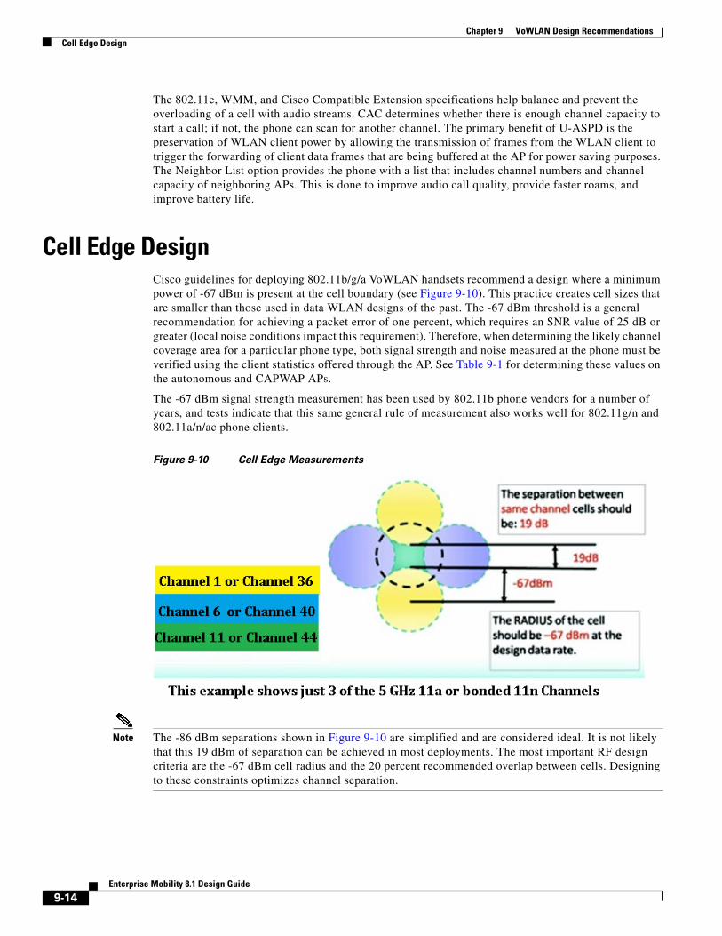
Cell Edge DesignCisco guidelines for deploying 802.11b/g/a VoWLAN handsets recommend a design where a minimum power of -67 dBm is present at the cell boundary (see Figure 9-10). This practice creates cell sizes that are smaller than those used in data WLAN designs of the past. The -67 dBm threshold is a general recommendation for achieving a packet error of one percent, which requires an SNR value of 25 dB or greater (local noise conditions impact this requirement). Therefore, when determining the likely channel coverage area for a particular phone type, both signal strength and noise measured at the phone must be verified using the client statistics offered through the AP. See Table 9-1 for determining these values on the autonomous and CAPWAP APs.
The -67 dBm signal strength measurement has been used by 802.11b phone vendors for a number of years, and tests indicate that this same general rule of measurement also works well for 802.11g/n and 802.11a/n/ac phone clients.
Figure 9-10 Cell Edge Measurements
Note The -86 dBm separations shown in Figure 9-10 are simplified and are considered ideal. It is not likely that this 19 dBm of separation can be achieved in most deployments. The most important RF design criteria are the -67 dBm cell radius and the 20 percent recommended overlap between cells. Designing to these constraints optimizes channel separation.
9-14Enterprise Mobility 8.1 Design Guide

Chapter 9 VoWLAN Design RecommendationsCell Edge Design
For 5 GHz cells, there is less concern about same channel separation because of the number of available non-overlapping channels. There are 20 channels in the 802.11a 5 GHz band so a two-channel separation is almost always possible. In contrast, the 2.4 GHz band has only three channels that do not overlap in frequency.
For both the 5 GHz and 2.4 GHz bands the cell edge must be at the floor level where a packet error rate of 1 percent is maintained at the highest data rate desired for a given channel. The data rate is 72 Mbps for an 802.11n on 2.4 GHz with a one spatial stream client.
The data rate is 150 Mbps for an 802.11n client on the 5 GHz band with a 40 MHz wide channel and with a one spatial stream client. A laptop running a softphone application such as Jabber can support three spatial streams and have a date rate to 450 Mbps on a 5 GHz, 40 MHz wide channel. Both an 802.11a client and an 802.11n client that is only 20 MHz wide and supporting one spatial stream can share Wi-Fi channel access on a 40 MHz wide channel with an 802.11ac three spatial stream client on a 80 MHz wide channel.
This type of client mixture and protocol mixture is part of the 802.11 specification. The compatibility for this type of client mixture on the same Wi-Fi frequencies is part of the 802.11n and 802.11ac specifications.
The major design question is how to define the coverage area for bandwidth and call capacity. Audio call capacity is about the same for 802.11n and 802.11ac as it was for 802.11g and 802.11a. This is because of the packet size of the audio G.711 or G.722 frame, which with AES encryption is less than 300 bytes. The small packet size and the ACK logic of the 802.11 specification creates a large overhead compared to large streaming applications. A video call generates both small audio packets and large video packets. The video packets are highly compressed and therefore spaced out in comparison to the audio. Cisco recommends as a guideline to establish the cell edge of coverage. Measure the distance from the AP that the phone is when the RSSI value of phone on the AP is -67 dBm.
802.11g and 802.11a phone clients can be capable of rates up to 54 Mbps. Current chip sets support many rates, but transmit power capabilities differ. Cisco highly recommends that all links between phone clients and APs be established using matching transmit power levels (see Dynamic Transmit Power Control).
Coverage cells can be created for specific data rates. For a high density deployment or a deployment where a large number of calls are required within a small floor space, 802.11a is recommended because of the number of channels and the 54 Mbps data rate. The lower data rates in 802.11a can be disabled, the 24 Mbps data rate can be set to required, while the 36 to 54 Mbps data rates can be left enabled.
After setting the cell edge of -67 dBm, determine where the error rate of 1 percent occurs, and then examine the SNR value.
The -67 dBm cell edge can be determined as follows:
• Set the phone to its desired transmit power.
• Set the AP to a matching transmit power.
• Place the AP and the desired antenna in the location where the phone will be used.
• With an active call, or while sending and receiving packets equal in size to the G711 codec, measure the signal level out to the -67 dBm cell edge.
Carefully examine the data sheets of the particular phone device to determine the transmit power levels and data rates supported by the phone device in a particular Wi-Fi band. For more information, refer the Data Sheets for Cisco Unified Wireless IP Phones.
The 2.4 GHz maximum transmit power levels vary on different channels and with different AP models. The 5 GHz maximum transmit power levels vary by model. The Cisco Aironet AP data sheets should be carefully reviewed to determine which AP model supports which data rates. Figure 9-11 shows an example of the maximum 5 GHz transmit power in dBm by channel.
9-15Enterprise Mobility 8.1 Design Guide

Chapter 9 VoWLAN Design RecommendationsDual Band Coverage Cells
Figure 9-11 Channel Power Assignment
The maximum permissible transmit power across the 5 GHz band varies by as much as 6 dB. This means that when using the maximum allowed transmit power throughout a site that allows all channels, there will not be equal cell coverage on all channels. It also means that if dynamic channel selection is used, the cell coverage edge can change based on the channel number. However, dynamic channel selection can be tuned. The default mode of dynamic channel selection accounts for the difference of maximum transmit power level by channel.
Cell transmit power on all APs should not exceed the maximum or desired transmit power of the phones. If the phone's maximum or set transmit power is 13 dBm, Cisco recommends that all APs have a maximum transmit power of 13 dBm. Therefore, the maximum transmit power on the AP should be set to an equal level or, if that is not possible, the next higher transmit power level. Equal transmit power is recommended to avoid one-way audio problems. The AP generally has better receiver sensitivity and diversity support than the phone, so it should be able to receive the slightly lower strength phone signal. See Dynamic Transmit Power Control for more information on equal transmit powers.
Dual Band Coverage CellsChapter 3, “WLAN RF Design Considerations” describes 2.4 GHz and 5 GHz channel coverage design. For a dual mode AP to provide equal cell coverage on both the 2.4 GHz and 5 GHz channels, the 2.4 GHz channel must have an equal (or usually lower) transmit power than the 5 GHz channel. At most sites the noise level in the SNR formula is lower by up to 10 dB. The receiver sensitivity of 802.11g radios is generally 2 dBm better than the same data rate on 802.11a radios. For example, the Cisco 7921G phone data sheet lists the receive sensitivity of -78 dBm at the data rate of 36 Mbps for 802.11g, and -76 dBm for 802.11a. Therefore, given the anticipated better noise floor of 10 dB, the 802.11a cell can do better by 8 dBm. Other details such as the difference in path loss between 802.11g and 802.11a keep this from being a direct ratio. However, if the same coverage cells are desired, reducing the 802.11g network by one or two power levels from the 802.11a network power levels should accomplish this goal.
9-16Enterprise Mobility 8.1 Design Guide
Chapter 9 VoWLAN Design RecommendationsDynamic Transmit Power Control
Dynamic Transmit Power ControlBy default, Cisco Aironet APs have dynamic transmit power control (DTPC) enabled. DTPC is automatic with Cisco WLCs but must be configured on autonomous APs.
The objective of DTPC is to reduce the chance of one-way audio because of an imbalance of transmit power between the AP and the Wi-Fi radio of the client. DTPC accomplishes this by:
• Setting the phones transmit power to match the transmit power of the APs.
• Having APs advertise their transmit power for the clients to learn.
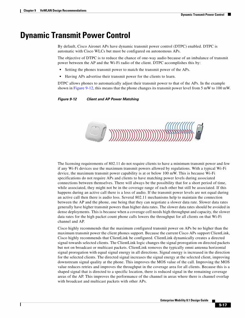
DTPC allows phones to automatically adjust their transmit power to that of the APs. In the example shown in Figure 9-12, this means that the phone changes its transmit power level from 5 mW to 100 mW.
Figure 9-12 Client and AP Power Matching
The licensing requirements of 802.11 do not require clients to have a minimum transmit power and few if any Wi-Fi devices use the maximum transmit powers allowed by regulations. With a typical Wi-Fi device, the maximum transmit power capability is at or below 100 mW. This is because Wi-Fi specifications do not require APs and clients to have matching power levels during associated connections between themselves. There will always be the possibility that for a short period of time, while associated, they might not be in the coverage range of each other but still be associated. If this happens during an active call there is a loss of audio. If the transmit power levels are not equal during an active call then there is audio loss. Several 802.11 mechanisms help to maintain the connection between the AP and the phone, one being that they can negotiate a slower data rate. Slower data rates generally have higher transmit powers than higher data rates. The slower data rates should be avoided in dense deployments. This is because when a coverage cell needs high throughput and capacity, the slower data rates for the high packet count phone calls lowers the throughput for all clients on that Wi-Fi channel and AP.
Cisco highly recommends that the maximum configured transmit power on APs be no higher than the maximum transmit power the client phones support. Because the current Cisco APs support ClientLink, Cisco highly recommends that ClientLink be configured. ClientLink dynamically creates a directed signal towards selected clients. The ClientLink logic changes the signal prorogation on directed packets but not on broadcast or multicast packets. ClientLink removes the typically omni antenna horizontal signal prorogation with equal signal energy in all directions. Signal energy is increased in the direction for the selected clients. The directed signal increases the signal energy at the selected client, improving downstream signal quality at the phone. This improves the MOS value of the call. Improving the MOS value reduces retries and improves the throughput in the coverage area for all clients. Because this is a shaped signal that is directed to a specific location, there is reduced signal in the remaining coverage areas of the AP. This improves the performance of the channel in areas where there is channel overlap with broadcast and multicast packets with other APs.
9-17Enterprise Mobility 8.1 Design Guide

Chapter 9 VoWLAN Design RecommendationsDynamic Transmit Power Control
Cisco recommends that each model of phone be tested for its Wi-Fi coverage range. The WLC reports the receive signal strength indicator (RSSI) of each client at the AP to which the phone is associated. The value shown in the RSSI field is the signal strength of a packet transmitted from the phone to the AP. The value indicates how strong the packet transmitted by the phone was at when it was received at the AP. It is recommended to check the coverage range of the phones and that the phones be placed at the estimated coverage edge of the AP. Then check the RSSI when a phone is on an active call. The goal is that at the cell edge (recommended -67dBm RSSI) the packets are sent at a high data rate. See Figure 9-10 for a reference to the cell edge for VoWLAN Wi-Fi coverage area range. The value of -39 shown in the figure is a very strong signal that is seen when the client phone or device is within a few feet of the AP.
Testing the phone's coverage has become more important with the advent of smartphones and tablets. Because the Wi-Fi feature sets of these devices are typically for the consumer market, these devices typically have few 802.11 features that are considered to support enterprise. The consumer orientation of most smartphones and tablets does not support DTPC. Therefore, Cisco recommends that the maximum transmit power for 2.4 GHz and 5 GHz be a dBm value that matches the 2.4 GHz and 5 GHz band maximum transmit power of your weakest smartphone or tablet. This WLC field value limits the transmit signal power of the APs, thereby helping to maintain a balance in range of the phone to the AP.
802.11r and 802.11k FeaturesIEEE 802.11k and 802.11r are key industry standards that enable seamless Basic Service Set (BSS) transitions in the WLAN environment. With WLAN 7.2 release, Cisco supports the 802.11r secure authentication Fast Transition protocol. The IEEE 802.11k specification was ratified in June 2008. The IEEE 802.11r specification was ratified in July 2008. 802.11r specification follows the 802.11e security specification of June 2004.
See a brief description of the 802.11k Specification.
See the 802.11k Specifications.
See a brief description of the 802.11r Specifications.
802.11k and 802.11k-enabled client devices send a request for a list of neighbor APs (a Neighbor List) from the APs they are currently associated with. The request is in the form of an 802.11 management frame known as an action packet. The AP responds with an action packet that contains a Neighbor List of APs on the same WLAN along with their Wi-Fi channel numbers.
From the response action packet the 802.11k client learns which APs are candidates for the next roam. The use of 802.11k radio resource management (RRM) algorithms allows smartphones to roam efficiently and quickly: a requirement for good call quality in an enterprise environment where on-call roams are common.
Cisco recommends that the 802.11k be configured in the WLC to enable radio resource management (RRM) to provide both 2.4 GHz and 5 GHz AP channel numbers in the Neighbor List response packets. Cisco also recommends the use of 5 GHz band Wi-Fi channels for not only VoWLAN calls but for all applications and devices.
With information from the Neighbor List, 802.11k clients do not need to probe all of the 2.4 GHz and 5 GHz channels to find an AP they can roam to. Not having to probe all of the channels reduces channel utilization on all channels, thereby increasing bandwidth on all channels. It also reduces roam times and improves the decisions made by the client. Additionally, it increases battery life of the device because it is neither changing the radio configuration for each channel nor sending probe requests on each channel. This prevents the devices from having to process all of the probe response frames.
9-18Enterprise Mobility 8.1 Design Guide

Chapter 9 VoWLAN Design RecommendationsDynamic Transmit Power Control
The 802.11r and 802.11e specifications both support the same authentication types: EAP-FAST, LEAP, EAP-TLS, EAP-TTLS, EAP-SIM, and PEAP versions 1 and 2. This security feature allows an 802.11r-enabled client to authenticate securely to an AP in an exchange of only four packets. Two of the packets are sent over the Ethernet wires that connect the APs to each other. The other two packets are sent on the Wi-Fi channels of each AP. This allows the 802.11r client to be authenticated securely to the AP that it is going to roam to before it actually roams. The result is the 802.11r client can be sending and receiving data, video, and audio packets after the roam without the delay of the authentication process. Because the 802.11 header is changed by the addition of the 802.11r parameters, the WLAN for 802.11r clients cannot be shared with clients that are not 802.11r-aware. This means that all clients that have the SSID assigned by the WLAN with 802.11r enabled must have Wi-Fi radio firmware that is aware of the 802.11r element in association packets. Limitations to 802.11r fast roaming are:
• Is supported on APs in autonomous mode but requires Wireless Domain Services (WDS).
• Roaming between local authentication and central authentication WLAN is not supported.
Cisco recommends that you use the 802.11r specification as it improves roam times because of a reduction in the number of packets sent over the Wi-Fi channel between a client that is already authenticated to the WLAN.
Interference Sources Local to the UserInterference can be local to the user but it is also likely to affect nearby users. Bluetooth is a popular RF protocol used in personal area networks that interferes with 2.4 GHz Wi-Fi channels. Figure 9-13 shows that the actual Bluetooth signal does span all of the 2.4 GHz channels used by 802.11b/g clients. This graphic is taken from an 802.11g audio call with a Bluetooth headset linked to the phone. Figure 9-14 also shows the jitter caused by the Bluetooth headset.
9-19Enterprise Mobility 8.1 Design Guide

Chapter 9 VoWLAN Design RecommendationsDynamic Transmit Power Control
Figure 9-13 Signal Pattern in the 802.11b/g 2.4 GHz Spectrum of a Typical Bluetooth Earpiece
In Figure 9-13 the purple line shows the Max Hold, the maximum transmit power that was reached during the test. The yellow line shows the maximum transmit power in the last sample period of ten seconds. The turquoise line shows the average transmit power over the period of the test. The vertical dashed blue lines separate the three non-overlapping 802.11b/g channels (Ch1, Ch6, and Ch11). The charting is from 2.400 GHz on the left to 2.500 GHz on the right. From the right edge of the Ch11 vertical blue line is the part of the 802.11 spectrum used in Europe and Japan. This capture was done with the AP and clients configured for the North American regulatory domain. This graph shows that the Bluetooth earpiece was easily transmitting outside of FCC regulations.
Notice that the Bluetooth signal is very narrow. Bluetooth transmits data on a single MHz of frequency, stops the transmission, moves to another frequency in the 802.11 2.4 GHz band, and then transmits data. This is repeated continually. The 802.11b and 802.11g signals are sent with a combined 22 MHz of frequency. The radio remains on that 22 MHz of frequency. This grouping of 22 MHz is referred to as the channel. The Max Hold line shows how strong the Bluetooth is while in search mode. The signal level is above that of a 50 mW (17 dBm) OFDM 802.11g radio. A signal of this strength and duration causes 802.11b/g phones to drop the VoWLAN call. Lesser strength Bluetooth signals cause jitter, resulting in a lower MOS value. Figure 9-14 shows an example of an Ethereal jitter analysis of three simultaneous phone calls, each using a Bluetooth earpiece.
9-20Enterprise Mobility 8.1 Design Guide

Chapter 9 VoWLAN Design RecommendationsDynamic Transmit Power Control
Figure 9-14 Jitter Analysis Example
All three calls were on the same AP and were to three other phones also on the same AP. For information on interference with Wi-Fi and Bluetooth, see the IEEE Report.
The factors that affect the impairments introduced to a Bluetooth TDM packet when colliding with Wi-Fi OFDM include:
• Relative power
• Bandwidth
• Mutual overlap
• Number of colliding OFDM signals
Simulations were performed on the effects of interference between a sample Wi-Fi OFDM packet and Bluetooth signals, as shown in Figure 9-15. The figure shows the Normal GMSK Bluetooth undistorted signal TDM characteristics. On the left is frequency versus time (MHz), and on the right is I/Q amplitudes.
9-21Enterprise Mobility 8.1 Design Guide

Chapter 9 VoWLAN Design RecommendationsDynamic Transmit Power Control
Figure 9-15 IEEE Waveform Simulations
As shown above in the Figure 9-15, the 625-second long hopping Bluetooth packet can interfere with more than one OFDM packet at a time, especially whenever high-rate OFDM mode packets (where the length of the packet is much shorter than that of Bluetooth) are subject to the collision.
9-22Enterprise Mobility 8.1 Design Guide