voltage-controlled sapphire oscillator: design ... vcso is an analog of the quartz...
TRANSCRIPT

IPN Progress Report 42-170 August 15, 2007
Voltage-Controlled Sapphire Oscillator: Design,Development, and Preliminary
PerformanceR. T. Wang,1 G. J. Dick,2 and R. L. Tjoelker1
We present the design for a new short-term frequency standard, the voltage-controlled sapphire oscillator, as a practical and lower-cost alternative to a cryogenicsapphire oscillator operating at liquid helium temperatures. Performance goals area frequency stability of 1×10⁻¹⁴ (1 second ≤ τ ≤ 100 seconds), more than 2 years ofcontinuous operation, and practical operability. Key elements include the sapphireresonator, low-power and long-life cryocooler, frequency compensation method, andcryo-Pound design. We report the design verification, experimental results, and testresults of the cryocooler environmental sensitivity, as well as a preliminary stabilitymeasurement.
I. Introduction
The voltage-controlled sapphire oscillator (VCSO) is a technology designed as a practical high-performance upgrade for applications presently limited by ultra-stable quartz oscillators. Its main featuresare cryogenic sapphire oscillator (CSO) capability with short-term stability of 1× 10⁻¹⁴ or better (1 sec-ond < τ < 1000 seconds) in a small transportable package, and the capability of 2 years or more ofcontinuous maintenance-free operation. Specific design factors and early progress were reported in [1,2].This VCSO is an analog of the quartz voltage-controlled crystal oscillator (VCXO) but with much higherperformance, and it is incorporated in a much reduced physical package as compared with previous cryo-genic sapphire oscillator units. The VCSO is expected to provide 10 times better frequency stability and20-dB close-in phase noise reduction at 32 GHz (Ka-band) as compared with the best available quartzoscillators. Small size and modest cryogenic requirements also make the VCSO technology an attractivecandidate to meet future space oscillator requirements.
Previous JPL-designed and -built cryocooled oscillators—the 10-K Compensated Sapphire Oscillator(CSO) [3] and the 40-K CSO [4]—provide state of the art short-term performance: 10−14 to 10−15
stability together with ultra-low close-in phase noise. However, they have operability limitations due totheir size, maintenance, and power requirements. Quartz oscillators are small, long-lived, and can beused in remote sites to clean up ultra-stable signals, but they substantially limit Deep Space Network
1 Tracking Systems and Applications Section.
2 Communications Architectures and Research Section.
The research described in this publication was carried out by the Jet Propulsion Laboratory, California Institute ofTechnology, under a contract with the National Aeronautics and Space Administration.
1

(DSN) phase noise performance at Ka-band and higher frequencies. While a truly miniature cryogenicsapphire oscillator is not yet within reach, an initial version that could reside in a 5-unit-high rack-mountchassis is. One promising cryocooler currently being evaluated at JPL for possible use in a DSN antennaarray is the Sunpower Stirling cycle cryocooler [5]. The cryocooler goals of the DSN array and a VCSOare similar, both requiring low cost, long operational life, and the lowest possible base temperature. TheSunpower cryocooler uses 150 W and provides 2 W of cooling power at 40 K. The cooler has a lifetime of50,000 hours (>5 years). The form factor of the cryocooler fits in a 25-cm-long, 7.5-cm-diameter cylinder.The VCSO would be very attractive as a modular upgrade in high-performance VCXO applications suchas clean-up loops (CULs), low-noise flywheel oscillators, and local oscillators (LOs) for high-performancepassive frequency standards. This is a much broader market than previous versions of the CSO havebeen able to reach, and several immediate NASA applications are the JPL Frequency Standard TestLaboratory (FSTL) and the DSN Frequency and Timing Subsystem (FTS).
The VCSO compensation methodology traces to the previously developed 40-K CSO [4], which es-tablished the low-drift and low gravity sensitivity (g-sensitivity) for a “self assembling” compensatedsilver/sapphire resonator design that demonstrated a quality factor (Q) of Q = 1×10⁸ at its temperatureturnover of about 37 K. Using a whispering gallery transverse electric (WGE)12,1,1 mode instead of theprevious WGE10,1,1 increases the diameter slightly but makes possible reuse of the previous silver spacerdesign, and it also moves the radio frequency (RF) fields away from the central region. The resonatorenclosure volume is reduced from that of the 40-K CSO by about 10 cc, with an inner diameter (ID) forthe shielding can of 3.55 cm and a height of 1.58 cm. This development extends present technology toa higher-frequency resonator (32 GHz instead of the present 16 GHz) for reduced size, g-sensitivity, andsize of the electronic packaging. The VCSO includes a new cryostat design and resonator interface to theselected cryocooler.
The most significant technical differences between the VCSO and previous CSO designs are due to thevery small cryocooler. Available Stirling coolers are small enough to allow a very attractive and smallphysical package, but their use also significantly impacts other aspects of the system. In particular, thesmaller cryocooler introduces larger mechanical vibrations than the large coolers that were previouslyused. However, a much higher mechanical frequency of operation (60 Hz versus 1.5 Hz) allows the effectsof these vibrations to be ameliorated by the combination of an electronically driven mechanical balancerand an RF clean-up loop incorporating an inexpensive quartz oscillator. These two systems togethereffectively eliminate the vibrations without impacting VCSO performance.
II. System Design
In the design of an ultra-high-stability oscillator, many interrelated parameters must be addressed.The key individual elements are resonator Q, temperature, vibration, cryocooler, frequency compensa-tion, resonator g-sensitivity, resonator mode configuration, resonator frequency, overall size, continuousoperation period, electronics, and cost. Key interrelated parameters are as follows:
(1) Operational temperature and Q. Sapphire Q is a function of temperature: Q(77K) ∼ 107,Q(4K) ∼ 109. It is possible to reach frequency stability of a few parts in 10−15 with lowertemperature operation. While a 4-K system can reach stability below 10−15, a standard at10−14 is achievable at much higher temperatures and would still be an order of magnitudebetter than the best quartz oscillators.
(2) Temperature and the cryocooler. The selected operational temperature depends on thedesigned turnover temperature of the sapphire resonator, and the achievable base temper-ature and cooling power of the cryocooler. Practical single-stage Stirling coolers can reacha base temperature of 33 K [5], which provides margins for dewar heat load design and anypossible cooling power degradation over long-term operation. The Sunpower cryocooleralso was chosen for simple long-life operation and low cost.
2

(3) Acceleration sensitivity and the cryocooler. Due to the 60-Hz vibration of the Stirlingcooler, vibration effects need to be minimized through an active balancer and electroniccrossover design. Detailed results were previously reported in [2]. A mechanical finite-element calculation program was used to design a configuration with 100 times lowerg-sensitivity with a center support geometry (see Fig. 1).
(4) RF frequency and resonator mode. The resonator frequency is calculated based on thesapphire resonator physical size and the desired mode electromagnetic configuration (seeFig. 2). Finite-element calculation is used to determine the sapphire gap tuning rate,mode frequency, resonator size, coupling port position, and copper-can size. Sapphirewhispering-gallery modes provide higher Q, limited only by the inherent sapphire perfor-mance. When used in Ka-band spacecraft tracking, a carefully selected output frequencyat 32 GHz directly provides low signal phase noise to users without additional frequencymultiplication. The higher operating frequency at 32 GHz for WGE12,1,1 results in asmaller resonator with a smaller copper can but does increase the complexity of the sil-ver spacer design. For initial tests, to obtain an efficient match from a coaxial cable tothe sapphire resonator, we use a Teflon-filled WR-19 coaxial/waveguide adapter togetherwith an impedance-matched alumina-filled tapered waveguide adapter. Subsequent testsrevealed it is possible to use a Teflon-filled direct waveguide without an alumina taper forcritical coupling.
1.7 cm
GAP
CENTER SUPPORT
SILVER SPACER
SAPPHIRE ELEMENTS
Fig. 1. Cylindrical cross section of self-assembling resonator design and component parts. Sapphire is in green and the silver parts in gray. Thermal expansion in the silver spacer adjusts the gap spacing to compensate the thermal dependence of sap-phire s dielectric constant. The final assembled unit is supported from its geometrical center, reducing acceleration sensi-tivity of the resonant frequency to less than 10−10/g.
3

Fig. 2. Finite-element calculation of electromagnetic fields for the WGE12,1,1 mode used to determine the container size and coupling port position: magnetic field azimuthal phase at (a) 0 deg and (b) 90 deg. Each color variation corresponds to an order of magnitude in magnetic field strength.
AXIS OF SYMMETRY CAN WALLS
MAGNETIC FIELD AZIMUTHAL PHASE = 0
MAGNETIC FIELD AZIMUTHAL PHASE = π/2
0
z
r 0 r
z
(a) (b)
(5) Frequency compensation and frequency drift. Stable operation can be achieved only near aturnover temperature at which frequency sensitivity to temperature fluctuation is near zero(see Fig. 3). Without such compensation, the burden on the temperature control wouldincrease by 1000 times. Commercially available temperature controllers lower the overallcost of the system. Frequency drift has historically been a substantial limitation in thermo-mechanical CSO operation. To address this issue, an interference fit design and selectionof a low-creep material at low temperatures were folded into the sapphire resonator design.Silver was selected for its thermal properties and also for ease of machining. An electricaldischarge machining (EDM) process was chosen for its lower cost, faster delivery, andpossible lower chance of contamination.
III. Sapphire Resonator Design and Verification
The first set of 32-GHz sapphire resonators was assembled, tested for high Q modes, and demonstratedthe turnover temperature. Figure 1 shows the cross section of the sapphire resonator assembly anda photograph of the sapphire/silver parts before assembly. Design requirements and verification arediscussed in the following.
A. Electromagnetic Design
The VCSO resonator is based strongly on the previous 16-GHz design. In particular, the reuse of thesilver spacer design allows use of an EDM manufacturing technique that has already been proven. Even
4

10
8
6
4
2
0
TEMPERATURE, K
32 36 40 44 48 52 56
Fig. 3. Initial measured turnover temperature near 43 K for 32.05-GHz mode with a quadratic coefficient of −1.94 x 10⁻⁸/K2. With 1-mK tem-perature control, the frequency stability can reach 2 x 10⁻¹⁴. After a gap spacing adjustment, the turnover temperature was lowered to 38.910 K.
12
OFF
SE
T FR
EQ
UE
NC
Y, k
Hz
though the resonator itself is significantly smaller, the reused silver spacer design does not require thatthe physical tolerances between the silver and sapphire parts be made more stringent. Additionally, ahigher thermo-mechanical tuning rate due to the longer length of the silver spacer relative to that of theresonator naturally gives a somewhat higher turnover temperature, a good match to the capabilities ofthe single-stage Stirling cooler.
Electromagnetic fields calculated for the WGE12,1,1 mode for the sapphire resonator are shown inFig. 2. This mode is a quasi-transverse electric mode with energy confined to the sapphire disks by thephenomenon of “total internal reflection” and with 12 full waves around its perimeter. Finite-elementcalculations allow optimization of the resonator parameters, such as balancing the can diameter againstlosses and establishing appropriate RF magnetic field values at the coupling port. The positions of thewalls of the can have been adjusted to give a copper can–limited quality factor of Q = 4 × 10⁸ and so toallow critical coupling with a waveguide port for the expected sapphire quality factor of Q ≈ 3 to 6×10⁷.The azimuthal mode number was chosen to be nφ = 12 (instead of the previously used nφ = 10) becauseRF losses due to in-phase magnetic fields reduced the quality factor copper-can Q to an unacceptablevalue. First attempts without the cut-out region at the resonator corners resulted in a low tuning rate andconsequent low value for its turnover temperature, the temperature where the net sensitivity of frequencyto temperature passes through zero. The thermo-mechanical compensation process results from variationof the gap between sapphire disks for the assembled resonator as a function of temperature. This variationis primarily due to the thermal expansion coefficient of the silver spacer. This temperature dependenceallows the effect of the thermal variation of sapphire’s dielectric constant to be cancelled by a properchoice of tuning rate for the resonator and so to achieve a zero net variation (i.e., turnover) at the desiredoperational temperature.
B. Mechanical Design
Early thermo-mechanically compensated sapphire resonators suffered from excessive frequency drift,showing values as high as 10−8/day [4]. For this reason, we use a design that reduces frequency drift dueto mechanical creep in several ways. First, the use of a silver spacer instead of the copper previouslyused provides much lower cryogenic creep values [6]. Secondly, as shown in Figs. 4 and 5, a design isused for which the primary loading forces are radial and for which the crucial longitudinal dimensions canbe somewhat isolated from the effects of radial creep by an appropriate design. These radial loading forces
5

SAPPHIRE NECK
SILVER SPACER
GRIP AREA
CENTRAL AXIS OF RESONATOR
Fig. 4. Mechanical finite-element model used to minimize frequency drifts due to mechanical creep at the silver−sapphire interface (a second mirror-image part is not shown). Colors show the longitudinal motion with a zero at the yel-low−green interface in the approximate center of the face, while arrows show the path for a quantitative plot shown in Fig. 5.
SA
PP
HIR
E F
AC
E
SAPPHIRE FACE
1.5
1.0
0.5
0.0
DISTANCE ALONG PATH, mm
0
Fig. 5. Mechanical displacements evaluated along the path described by the arrows in Fig. 4, shown as the fraction of an applied radial displacement at the grip area (see Fig. 4). Careful adjustment of the sapphire dimensions in the grip region allows longitudinal displacement at the sapphire face to be reduced to less than 1 percent of the applied displacement.
1 2 3 4 5 6 7 8 9 10 11 12
SAPPHIRE NECK
TOTAL DISPLACEMENT
LONGITUDINAL DISPLACEMENT
FR
AC
TIO
NA
L D
ISP
LAC
EM
EN
T
6

result from the “self-assembling design” in which the silver spacer grips both the sapphire disks and thecentral sapphire support rod as the parts are cooled, resulting in small but usable clearances between thehorizontal surfaces that provide support prior to cooldown.
A partial view of the resonator assembly is shown in Fig. 4 to illustrate results of the mechanicalfinite-element calculation. Here the spacer is given an (unphysical) radial-only thermal dependence andcooled, with the grip area constrained longitudinally. The sapphire model geometry (e.g., the height) isvaried to give a zero for longitudinal motion at the center of the sapphire face. Quantitative results ofthis calculation are shown in Fig. 5, which shows longitudinal displacement reduced to ≈1 percent of theapplied radial displacement. A similar set of calculations and optimizations is also realized for changesin the grip length of the spacer due to radial pressure at the inside center of the spacer where it grips thesapphire support rod.
C. Experimental Results
A sapphire resonator was assembled and cooled to 40 K for high Q mode scanning between 26.0 and38.5 GHz. The desired mode frequency was verified at 32.05 GHz, a value +0.15 percent higher thancalculated. After adjustment of the gap spacing, the turnover temperature was verified to be 38.910 K,lower than the calculated value of 40 to 50 K. Although lower than expected, it is still within the rangeof current cryocooler cooling power. The measured Q value is 10 million, which is less than the expectedvalue of 20 million at 40 K. Q values as high as 80 million have been observed, as shown in Fig. 6.The VCSO sapphire/silver assembly design allows for frequency repeatability after the disassembly andcleaning processes. This has been demonstrated in the early stages.
IV. Cryocooler Requirements and Tests
A cryocooler is required for maintaining the sapphire resonator at a low temperature to obtain a highQ factor. At the same time, the cryocooler vibration needs to be minimized. Other cooling methods, suchas liquid helium, that need regular refill are not practical for long-term operation. The overall cryocoolerrequirements are a base temperature near 40 K, low input power, light weight, low cost, long life, andmanageable environmental sensitivity.
106
FREQUENCY, GHz
30
Fig. 6. Examples of high-Q modes found between 30 and 35 GHz. Line-connected data points are the possible mode sequence identified by finite-element method (FEM) calculation.
31 32 33 34 35
Q, c
oupl
ed
107
108
109
7

A. Functional Tests
The CryoTel cryocooler from Sunpower, Inc. has a rated lifetime of 50,000 hours and requires an inputpower of ≈150 W. The cooler itself and the interface to the sapphire resonator are shown in Fig. 7. Thecooler is available with passive or active balancers to reduce vibration levels. The passive balancer reducesvibrations by ≈10 dB to approximately 0.3-g root-mean-square (rms), a reduction that is enhanced byaddition of an electrical voice-coil mechanical driver and user-supplied electronics. We have operated thecooler continuously for 5 months and observed no failures or performance degradation. The cooler controlsystem supports constant temperature and constant stroke operational modes. Because of the need toreduce cooler vibrations by an active feedback system, we use the constant stroke mode to reduce theburden on control of that system. Figure 8 shows measured values for ultimate temperature as a functionof programmed stroke length.
B. Vibration Control
A drive electronics system to obtain active vibration cancellation has been developed. The circuit isdesigned to cancel the first two harmonics by manual adjustment of their phase and amplitudes. Some-what surprisingly, the 60-Hz drive for the cooler itself (and which we use as input to our circuit) consistsof a pulse-width modulation (PWM) square-wave signal at 420 Hz with inclusion of a 420-Hz notch filter.The effectiveness of the cancellation of the two vibration harmonics is shown in Fig. 9. The requirementsof a 25-dB reduction at 60 Hz and of 16 dB at 120 Hz are more than met. The 55-dB reduction shownin the figure cannot be held in the long term. Overnight values more typically showed a 40-dB reduc-tion. These values are sufficiently good that it is not clear whether an adaptive system will be requiredfor long-term operation. Also, somewhat surprisingly, varying the cryocooler stroke gave rise to some20-dB smaller degradation than would be expected for a constant amplitude cancellation model, indicat-ing that the variations in cooler vibration levels and the active compensator are largely compensatingeach other. Disabling the passive vibration cancellation system by shorting the voice-coil terminal resultsin a vibration level at 60 Hz that is 10-dB larger than shown here (a value of approximately 1-g rms).
Fig. 7. The CryoTel cryocooler as tested without the control electronics and control computer. The cooler and vibration-cancelling driver are shown without a cylindrical air duct cover that channels air from the blower at the right through a heat exchanger at its left end. The cool-er s cold finger extends into the vacuum fittings at the left and will be replaced with some-what larger fittings to accommodate the resonator and heat shield; a vertical, downward-hanging configuration is planned.
CRYOCOOLER VIBRATION BALANCER
8

38.5
STROKE, mm
3
Fig. 8. Base temperature versus stroke length as measured for the cooler configuration in a horizontal position.
4 5 6 7
TE
MP
ER
AT
UR
E, K
39.0
39.5
40.0
40.5
41.0
41.5
42.0
42.5
43.0
55-dB REDUCTION AT 60 Hz
38-dB REDUCTION AT 120 Hz
Fig. 9. Scanned image from a plotter showing an acceleration spectrum for the CryoTel cooler measured with and without active vibration cancellation. The first two vibration harmonics and their reduction values are indicated in the fig-ure. A further 25-dB reduction by an RF clean-up loop (see Fig. 11) is required to achieve the overall 60-dB bright-line reduction goal.
9
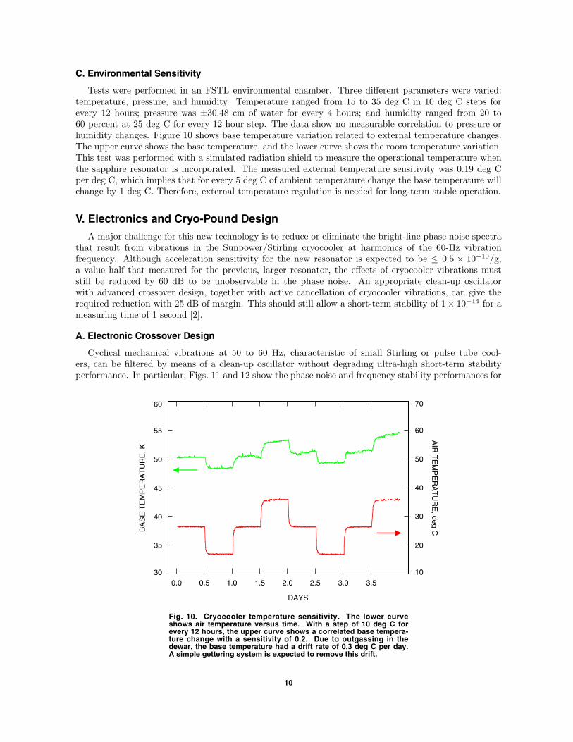
C. Environmental Sensitivity
Tests were performed in an FSTL environmental chamber. Three different parameters were varied:temperature, pressure, and humidity. Temperature ranged from 15 to 35 deg C in 10 deg C steps forevery 12 hours; pressure was ±30.48 cm of water for every 4 hours; and humidity ranged from 20 to60 percent at 25 deg C for every 12-hour step. The data show no measurable correlation to pressure orhumidity changes. Figure 10 shows base temperature variation related to external temperature changes.The upper curve shows the base temperature, and the lower curve shows the room temperature variation.This test was performed with a simulated radiation shield to measure the operational temperature whenthe sapphire resonator is incorporated. The measured external temperature sensitivity was 0.19 deg Cper deg C, which implies that for every 5 deg C of ambient temperature change the base temperature willchange by 1 deg C. Therefore, external temperature regulation is needed for long-term stable operation.
V. Electronics and Cryo-Pound Design
A major challenge for this new technology is to reduce or eliminate the bright-line phase noise spectrathat result from vibrations in the Sunpower/Stirling cryocooler at harmonics of the 60-Hz vibrationfrequency. Although acceleration sensitivity for the new resonator is expected to be ≤ 0.5 × 10⁻¹⁰/g,a value half that measured for the previous, larger resonator, the effects of cryocooler vibrations muststill be reduced by 60 dB to be unobservable in the phase noise. An appropriate clean-up oscillatorwith advanced crossover design, together with active cancellation of cryocooler vibrations, can give therequired reduction with 25 dB of margin. This should still allow a short-term stability of 1× 10⁻¹⁴ for ameasuring time of 1 second [2].
A. Electronic Crossover Design
Cyclical mechanical vibrations at 50 to 60 Hz, characteristic of small Stirling or pulse tube cool-ers, can be filtered by means of a clean-up oscillator without degrading ultra-high short-term stabilityperformance. In particular, Figs. 11 and 12 show the phase noise and frequency stability performances for
30
DAYS
0.0
Fig. 10. Cryocooler temperature sensitivity. The lower curve shows air temperature versus time. With a step of 10 deg C for every 12 hours, the upper curve shows a correlated base tempera-ture change with a sensitivity of 0.2. Due to outgassing in the dewar, the base temperature had a drift rate of 0.3 deg C per day. A simple gettering system is expected to remove this drift.
BA
SE
TE
MP
ER
AT
UR
E, K
35
40
45
50
55
60
0.5 1.0 1.5 2.0 2.5 3.0 3.510
20
30
40
50
60
70
AIR
TE
MP
ER
AT
UR
E, deg C
10

log Frequency, Hz
−2
Fig. 11. A clean-up oscillator can help to reduce vibration-inducedphase-noise spurs to negligible levels. Shown here are phase-noiseplots for 5-MHz and 100-MHz candidate clean-up oscillators, exampleVCSO phase noise with a single 60-Hz vibration harmonic, and com-bined (crossed-over) phase noise for the VCSO together with each can-didate clean-up oscillator. For comparison, the phase noise for alloscillators is scaled to 5 MHz. The crossover design here has a unitygain frequency of 25 Hz and includes notch filters for the first threevibration harmonics. Operating together with an active vibration-cancellation system described in Fig. 9, the combined system isexpected to reduce vibration harmonics by more than 60 dB.
1 2 30−1
−200
−180
−160
−140
−120
−100
S (
f ),
dB
c/H
z
60-Hz SPIKE
VCSO + 5-MHz QUARTZ
VCSO + 100-MHz QUARTZ
SAPPHIRE VCSO
5-MHz QUARTZ
100-MHz QUARTZ
several clean-up oscillators and for a crossover design that provides highly tuned rejection at the fun-damental of the cryocooler vibration frequency and its first two harmonics. The choice of unity gainor crossover frequency for the crossover circuit balances the need for the clean-up oscillator to be effec-tive at high frequencies (favoring a low crossover frequency), while effectively ignoring its higher noiseat lower frequencies (favoring a higher crossover frequency)—higher noise that would otherwise degradethe frequency stability of the combined system. With an optimal crossover frequency of only 25 Hz asdetermined by this trade-off, rejection of the vibration harmonics is largely up to the notch filters. Wefind that these filters require a Q ≈ 5 to 10 to minimize their impact on lower frequencies and on thephase margin of the loop. However, such filters will have a substantial sensitivity to component variationwith temperature, and so a software method was developed to evaluate non-ideal “balanced tee” notchfilter performance. Based on these calculations, we have determined that the required 40-dB reductionfor the harmonics can be held for a 1 deg C variation of the crossover electronics interior.
A cryo-Pound design promising improvements to medium- and long-term stability using a new cryo-genic Pound circuit methodology is discussed in [7]. The following gives a brief description of the principaland demonstrated results.
In a cryogenic oscillator system, temperature variations in the microwave components between thecryogenic resonator and the room-temperature phase modulator may give rise to false Pound signals.Specifically for the oscillator described in [8], voltage standing wave ratio (VSWR)-induced standing
11

VCSO + 100-MHz QUARTZ
TIME, s
Fig. 12. Calculated Allan deviation for the phase-noise models described in Fig. 11. The crossed-over 5-MHz clean-up case is indistinguishable from the VCSO itself. Most significant is the ability to achieve the target 1 x 10⁻¹⁴ stability at 1 s with an inex-pensive and small low-noise 100-MHz quartz clean-up oscillator, as is shown here.
1 10 1000.1
10−15
ALL
AN
DE
VIA
TIO
N
VCSO + 5-MHz QUARTZ
5-MHz QUARTZ
100-MHz QUARTZ
10−14
10−13
10−12
10−11
waves in the RF transmission line entering the cryostat were estimated to give rise to a relative frequencyvariation of 1 × 10⁻¹³ in the presence of temperature variations of 10 K. The false Pound signals weredue to an induced linear variation of the amplitudes across the phase modulation (PM) spectrum.
Our goal is to eliminate the sensitivity of the oscillator to the above-described temperature fluctua-tions in the microwave components kept at room temperature. This is achieved by integrating all theRF components in the Pound scheme into the highly stabilized thermal environment that the sapphireresonator is placed in. Specifically, both the phase modulation of the RF carrier and the detection of theamplitude modulation (AM) component are included in the cryogenic part of the oscillator. The criticalcomponent in this all-cryogenic Pound circuit is the tunnel diode, which is used both as phase modulatorand AM detector (see Fig. 13). This diode was chosen because it functions at low temperatures and haslow noise. We find experimentally that the new Pound circuit has a sensitivity of 0.1 mV/Hz, whichcorresponds to a calculated stability of 4 × 10⁻¹⁶/
√τ .
In our first experimental investigations of the all-cryogenic Pound circuit, we achieved a stability of1×10−13 at 1 second. Although we are still some way from the predicted possible performance, the basicprinciple has been illustrated. Finally, the demonstration was performed at 16 GHz, and the all-cryogenicPound circuit is expected to work at 32 GHz, which can be incorporated into the VCSO in the future.
12

SAPPHIRE RESONATOR LOADED Q OF
60 MILLION
Q
16 GHz
PHASE SHIFTER
3-dB COUPLERS
TUNNEL DIODE MODULATOR
40-kHz MODULATION SIGNAL + DC BIAS
6-dB COUPLER
AM NULL OUTPUT
POUND SIGNAL OUTPUT
TUNNEL DIODE DETECTORS
50Ω
50Ω
Fig. 13. The new cryogenic Pound circuit. The tunnel diode modulator is DC biased, and the phase shifter is adjusted so that the upper diode detector gives minimal output while at the same time having high power in the modulation side bands. The power in the side bands is monitored through a weakly coupled port inserted immediately to the right of the left circulator (not shown). The carrier signal (here 16 GHz) enters the cryogenic environment, gets phase modulated, and is reflected from the resonator. In general this reflection contains an AM component that is detected in a tunnel diode, thus providing the Pound sig-nal.
VI. Integration and Initial Tests
Due to funding considerations, an initial measurement was hastily performed. To accomplish this ayear ahead of schedule required that several shortcuts, such as the following, be adopted:
(1) Q value. The Q value is at 10 million (less than the expected value of 20 million). Q valuesas high as 80 million were observed in some modes.
(2) Coupling. The coupling of the resonator is not yet “near critical.” With minor modifica-tions, we would expect to approach critical coupling, which will increase the signal-to-noiseratio.
(3) Electronics. We reused the old 40-K CSO electronics by doubling its 16-GHz frequencyoutput. Noise characterizations of the frequency doublers and amplifiers were not per-formed due to lack of resources and time. Also, the 16-GHz loop was not optimized forthis operation.
(4) Detector. A 32-GHz tunnel diode detector was used “as is” without characterization of itsnoise level and without checking the best performance input level.
(5) Cryocooler. We reused the 40-K CSO pulse tube cooler instead of the intended Sunpowercryocooler and attached the resonator directly to the cold stage for a simplified setup.
With the above multiple compromises, the initial stability measurement shows 3.7×10⁻¹³ at a 1-secondmeasurement time, and Fig. 14 shows the measured frequency stability from 1 s to 100 s. Frequencystability is expected to reach 1×10⁻¹⁴ at a 1-second measurement time with the original proposed setup.
13

EXPECTED VCSO
BEST QUARTZ
TESTED AGAINST HYDROGEN MASER
10−15
MEASUREMENT TIME, s
1
Fig. 14. Preliminary stability measurement of 3.7 x 10⁻¹³ at a 1-s measurement time. Shortcuts were made to acceler-ate this demonstration; they involved reusing previous electronics and not characterizing critical components used in the stability demonstration. A 1 x 10⁻¹⁴ perfor-mance is expected with proper setup and characterization.
10 100
FR
EQ
UE
NC
Y S
TA
BIL
ITY
10−14
10−13
10−12
10−11
VII. Conclusion
We reported on the overall design, development, and verification of a practical voltage-controlledsapphire oscillator. The first 32-GHz sapphire resonator was assembled and tested at cryogenic temper-atures. Various high-Q modes were identified and compared to finite-element calculations. The desiredmode shows a frequency of 32.05 GHz and a turnover temperature of 38.910 K. Measured Q values wereas high as 80 million. Several turnover temperatures were found between 40 and 60 K.
The Sunpower cryocooler was tested for temperature, pressure, and humidity sensitivity. The basetemperature had a sensitivity of 0.19 deg C/deg C of room temperature. No sensitivity to pressure orhumidity was measured.
Future work will focus on demonstrating improved stability, integrating the Stirling cryocooler andsapphire resonator, designing and attaching vibration-reduction electronics, and installing a cryogenicPound loop. The final goal is to demonstrate a short-term frequency stability of 1 × 10⁻¹⁴ with a lowdrift of ∼ 10−14 per day in a compact, low-cost system for long-term operation.
Acknowledgment
The authors thank William Diener for technical assistance in setting up stabilitymeasurements with an FSTL hydrogen maser and 10-K CSO.
14

References
[1] R. T. Wang, G. J. Dick, and R. L. Tjoelker, “Progress Report of A New Sap-phire Oscillator,” Proceedings of the 2006 IEEE International Frequency ControlSymposium, Miami, Florida, pp. 691–694, 2006.
[2] G. J. Dick, R. T. Wang, R. L. Tjoelker, and R. Basu, “Design and ProgressReport for Compact Cryocooled Sapphire Oscillator ‘VCSO’,” Proceedings ofthe 2005 IEEE International Frequency Control Symposium, Vancouver, Canada,pp. 363–367, 2005.
[3] G. J. Dick and R. T. Wang, “Stability and Phase Noise Tests of Two Cryo-Cooled Sapphire Oscillators,” 13th EFTF and 1999 IEEE Frequency ControlSymposium, Besancon, France, pp. 548–551, April 1999.
[4] R. T. Wang and G. J. Dick, “High Stability 40 Kelvin Cryo-Cooled SapphireOscillator,” Proceedings of the 2003 IEEE International Frequency Control Sym-posium, Tampa, Florida, pp. 371–375, 2003.
[5] CryoTel cryocooler by Sunpower Inc.http://www.sunpower.com/lib/sitefiles/pdf/cryo CT.pdf
[6] R. Shelby and J. Fontanella, “The Low Temperature Electrical Properties ofSome Anisotropic Crystals,” J. Phys. Chem. Solids, vol. 41, pp. 69–74, 1980.
[7] R. Basu, G. J. Dick, and R. T. Wang, “Novel Design of an All-Cryogenic RFPound Circuit,” Proceedings of the 2005 IEEE International Frequency ControlSymposium, Vancouver, British Columbia, Canada, pp. 562–568, 2005.
[8] G. J. Dick and R. T. Wang, “Stability and Phase Noise Tests of Two Cryo-CooledSapphire Oscillators,” IEEE Trans. UFFC, vol. 47, no. 5, pp. 1098–1101, 2000.
15