saw products - vectron · 5 voltage controlled saw oscillators (vcso) modules vs-800 series vcso...
TRANSCRIPT
SAW Products
SAW modules
SAW IF, RF, and integrated multi-band filter solutions
Frequency range from 30 MHz to 2.7 GHz
High-Q SAW narrow-band filters
High-volume, cost-efficient manufacturing capabilities
Dispersive and non-dispersive SAW delay lines
Voltage-controlled SAW oscillators (VCSO)
2
SAW Filter Impedance Matching Networks
How Do SAW Filters Work?
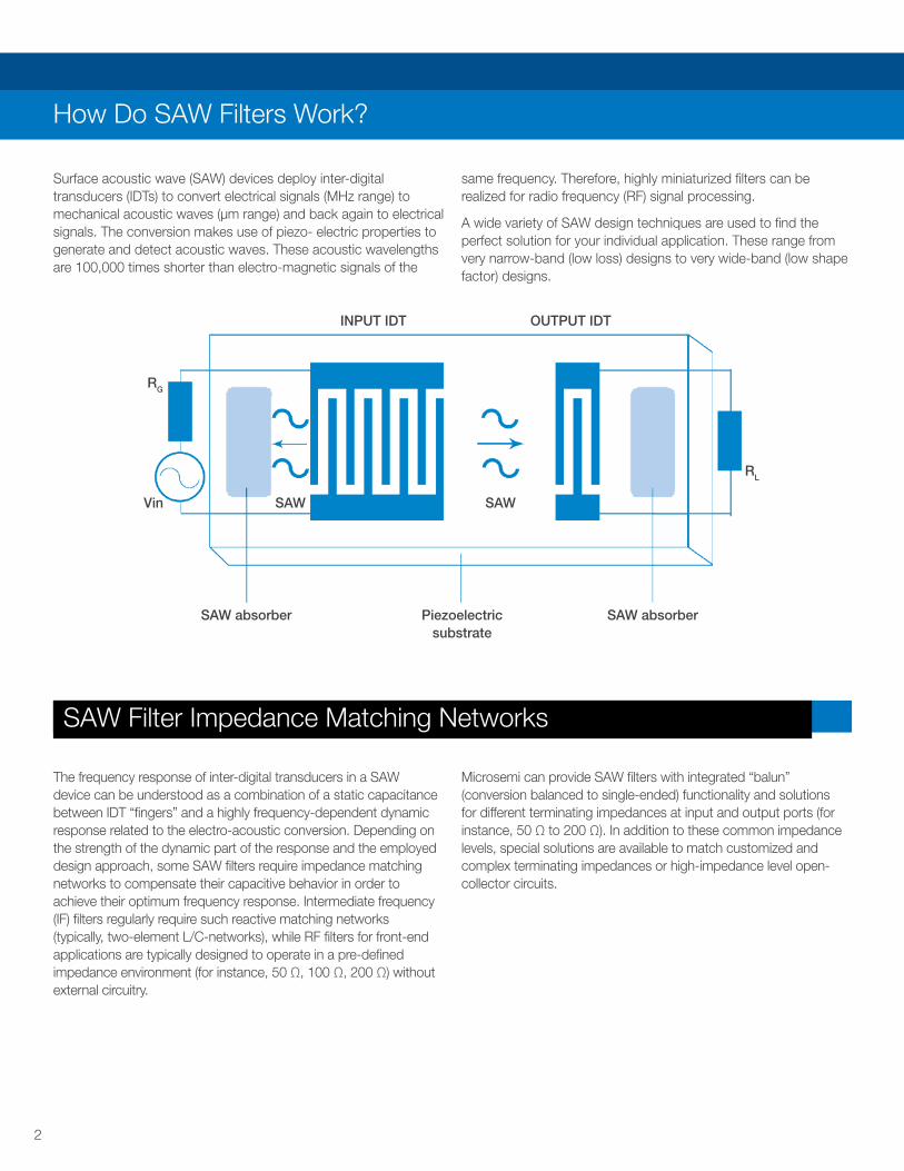
Surface acoustic wave (SAW) devices deploy inter-digital transducers (IDTs) to convert electrical signals (MHz range) to mechanical acoustic waves (μm range) and back again to electrical signals. The conversion makes use of piezo- electric properties to generate and detect acoustic waves. These acoustic wavelengths are 100,000 times shorter than electro-magnetic signals of the
same frequency. Therefore, highly miniaturized filters can be realized for radio frequency (RF) signal processing.
A wide variety of SAW design techniques are used to find the perfect solution for your individual application. These range from very narrow-band (low loss) designs to very wide-band (low shape factor) designs.
The frequency response of inter-digital transducers in a SAW device can be understood as a combination of a static capacitance between IDT “fingers” and a highly frequency-dependent dynamic response related to the electro-acoustic conversion. Depending on the strength of the dynamic part of the response and the employed design approach, some SAW filters require impedance matching networks to compensate their capacitive behavior in order to achieve their optimum frequency response. Intermediate frequency (IF) filters regularly require such reactive matching networks (typically, two-element L/C-networks), while RF filters for front-end applications are typically designed to operate in a pre-defined impedance environment (for instance, 50 Ω, 100 Ω, 200 Ω) without external circuitry.
Microsemi can provide SAW filters with integrated “balun” (conversion balanced to single-ended) functionality and solutions for different terminating impedances at input and output ports (for instance, 50 Ω to 200 Ω). In addition to these common impedance levels, special solutions are available to match customized and complex terminating impedances or high-impedance level open-collector circuits.
SAW absorber Piezoelectric substrate
SAW absorber
INPUT IDT OUTPUT IDT
RL
RG
Vin SAW SAW
3
RF Filters
IF Filters
To achieve high-performance heterodyne RF transceiver systems, highly selective filters for the intermediate frequency (IF) stage are mandatory. For such filters, system designers focus on highly linear amplitude and phase response within the desired filter pass band, as well as the steepest possible roll-off to achieve maximum adjacent channel suppression. Microsemi uses a large variety of different SAW filter design approaches to fulfill these requirements for all kinds of applications, in line with moderate insertion loss to limit amplification requirements and power consumption in the IF stage.
Extensive use of resonant and recursive design approaches, known in the digital world as infinite impulse response (IIR) filters, ensure maximum performance in combination with minimum size, whereas design approaches equivalent to finite impulse response (FIR) filters allow for realization of filter shape factors (ratio of stop-band and pass-band width) very close to the theoretical limit (that is, even below 1.05).
Microsemi’s SAW IF filters are found in all kinds of high-performance RF systems, from communications to aerospace and defense systems, in
medical and industrial electronics, and countless other applications.
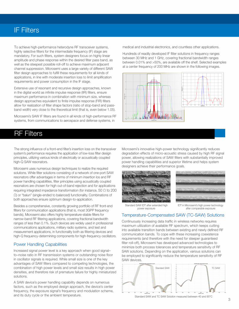
Hundreds of readily developed IF filter solutions in frequency ranges between 30 MHz and 1 GHz, covering fractional bandwidth ranges between 0.01% and >50%, are available off the shelf. Selected examples at a center frequency of 200 MHz are shown in the following images.
The strong influence of a front-end filter’s insertion loss on the transceiver system’s performance requires the application of low-loss filter design principles, utilizing various kinds of electrically or acoustically coupled high-Q SAW resonators.
Microsemi uses numerous design techniques to realize the required solutions. While filter solutions consisting of a network of one-port SAW resonators offer advantages in terms of minimum insertion los and RF power handling capabilities, filter principles using acoustically coupled resonators are chosen for high out-of-band rejection and for applications requiring integrated impedance transformation (for instance, 50 Ω to 200 Ω) or “balun” (single-ended to balanced) functionality. Combinations of both approaches ensure optimum design-to-application.
Besides a comprehensive, constantly growing portfolio of RF front-end filters for communication applications (that is, most 3GPP frequency bands), Microsemi also offers highly temperature-stable filters for narrow-band RF filtering applications, covering fractional bandwidth ranges of less than 0.1%. Such devices are widely used in professional communications applications, military radio systems, and test and measurement applications, in functionality both as filtering devices and high-Q frequency-determining components for high-frequency oscillators.
Power Handling Capabilities Increased signal power level is a key approach when good signal–to–noise ratio in RF transmission systems or outstanding noise floor in oscillator signals is required. While small size is one of the key advantages of SAW filters compared to competing technologies, the combination of high power levels and small size results in high power densities, and therefore risk of premature failure for highly miniaturized solutions.
A SAW device’s power handling capability depends on numerous factors, such as the employed design approach, the device’s center frequency, the exposure signal’s frequency and modulation scheme, and its duty cycle or the ambient temperature.
Microsemi’s innovative high-power technology significantly reduces degradation effects of micro-acoustic stress caused by high RF signal power, allowing realizations of SAW filters with substantially improved power handling capabilities and superior lifetime and helps system designers achieve their performance goals.
Temperature-Compensated SAW (TC-SAW) Solutions Continuously increasing data traffic in wireless networks requires maximum utilization of available RF spectrum, which keeps cutting into available transition bands between existing and newly defined RF communication bands. To cope with these increasing coexistence requirements (and therefore with the need for steeper guaranteed filter roll-off), Microsemi has developed advanced technologies to minimize both process tolerances and temperature sensitivity of RF SAW solutions. Depending on the application, various solutions can be employed to significantly reduce the temperature sensitivity of RF SAW devices.
Standard SAW IDT after extended high power exposure
IDT in Microsemi’s high power technology after comparable exposure
Standard SAW and TC SAW Solution measured between-40 and 90°C
TC SAWStandard SAW
4
Integrated Filter Solutions
Delay Lines
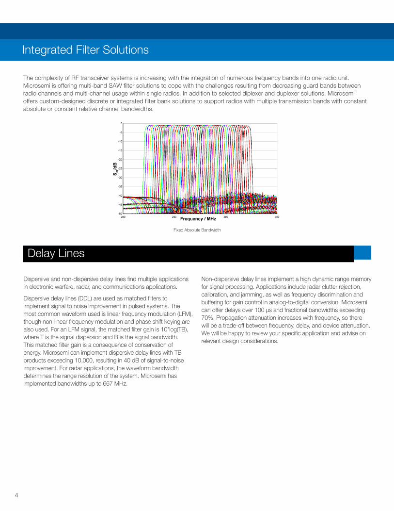
The complexity of RF transceiver systems is increasing with the integration of numerous frequency bands into one radio unit. Microsemi is offering multi-band SAW filter solutions to cope with the challenges resulting from decreasing guard bands between radio channels and multi-channel usage within single radios. In addition to selected diplexer and duplexer solutions, Microsemi offers custom-designed discrete or integrated filter bank solutions to support radios with multiple transmission bands with constant absolute or constant relative channel bandwidths.
Dispersive and non-dispersive delay lines find multiple applications in electronic warfare, radar, and communications applications.
Dispersive delay lines (DDL) are used as matched filters to implement signal to noise improvement in pulsed systems. The most common waveform used is linear frequency modulation (LFM), though non-linear frequency modulation and phase shift keying are also used. For an LFM signal, the matched filter gain is 10*log(TB), where T is the signal dispersion and B is the signal bandwidth. This matched filter gain is a consequence of conservation of energy. Microsemi can implement dispersive delay lines with TB products exceeding 10,000, resulting in 40 dB of signal-to-noise improvement. For radar applications, the waveform bandwidth determines the range resolution of the system. Microsemi has implemented bandwidths up to 667 MHz.
Non-dispersive delay lines implement a high dynamic range memory for signal processing. Applications include radar clutter rejection, calibration, and jamming, as well as frequency discrimination and buffering for gain control in analog-to-digital conversion. Microsemi can offer delays over 100 μs and fractional bandwidths exceeding 70%. Propagation attenuation increases with frequency, so there will be a trade-off between frequency, delay, and device attenuation. We will be happy to review your specific application and advise on relevant design considerations.
Fixed Absolute Bandwidth
5
Voltage Controlled SAW Oscillators (VCSO)
Modules
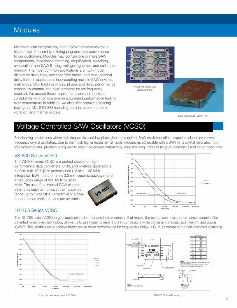
VS-800 Series VCSOThe VS-800 series VCSO is a perfect choice for high-performance data converters, OTN, and wireless applications. It offers sub-10 fs jitter performance (12 kHz – 20 MHz integration BW) in a 5.0 mm × 3.2 mm ceramic package, and a frequency range of 800 MHz to 3200 MHz. The use of an internal SAW element eliminates sub-harmonics in the frequency range up to 1600 MHz. Differential or single-ended output configurations are available.
For clocking applications where high frequencies and low phase jitter are required, SAW oscillators offer a superior solution over lower frequency crystal oscillators. Due to the much higher fundamental mode frequencies achievable with a SAW vs. a crystal resonator, no or less frequency multiplication is required to reach the desired output frequency, resulting in less or no (sub-)harmonics and better noise floor.
101765 Series VCSO
The 101765 series VCSO targets applications in radar and instrumentation that require the best phase noise performance available. Our patented micro-oven technology allows us to use higher Q resonators in our designs while consuming modest size, weight, and power (SWaP). This enables us to achieve better phase noise performance for frequencies below 1 GHz (as compared to non-ovenized solutions).
Microsemi can integrate any of our SAW components into a higher level of assembly, offering plug-and-play convenience to our customers. Modules may contain one or more SAW components, impedance matching, amplification, switching, ovenization, non-SAW filtering, voltage regulation, and calibration memory. The most common applications are multi-mode dispersive delay lines, switched filter banks, and multi-channel delay lines. In applications incorporating multiple SAW devices, matching and/or tracking of loss, phase, and delay performance channel-to-channel and over-temperature are frequently required. We accept these requirements and demonstrate compliance with comprehensive automated performance testing over temperature. In addition, we also offer popular screening testing per MIL-STD-883 including burn-in, shock, random vibration, and thermal cycling.
Example performance at 750 MHz 101765 Outline Drawing
4 Channel Delay Line With Matching
Multi-mode DDL With Oven
-170
-160
-150
-140
-130
-120
-110
-100
-90
-80
-70
-60
100 1,000 10,000 100,000 1,000,000 10,000,000 100,000,000
VS-8
00 V
CSO
Serie
s Pha
se N
oise
(dBc
/Hz)
Offset (Hz)
800MHz
2949MHz
2949 MHz design800 MHz design
Exceeds -180 dBc/Hz
6
Applications
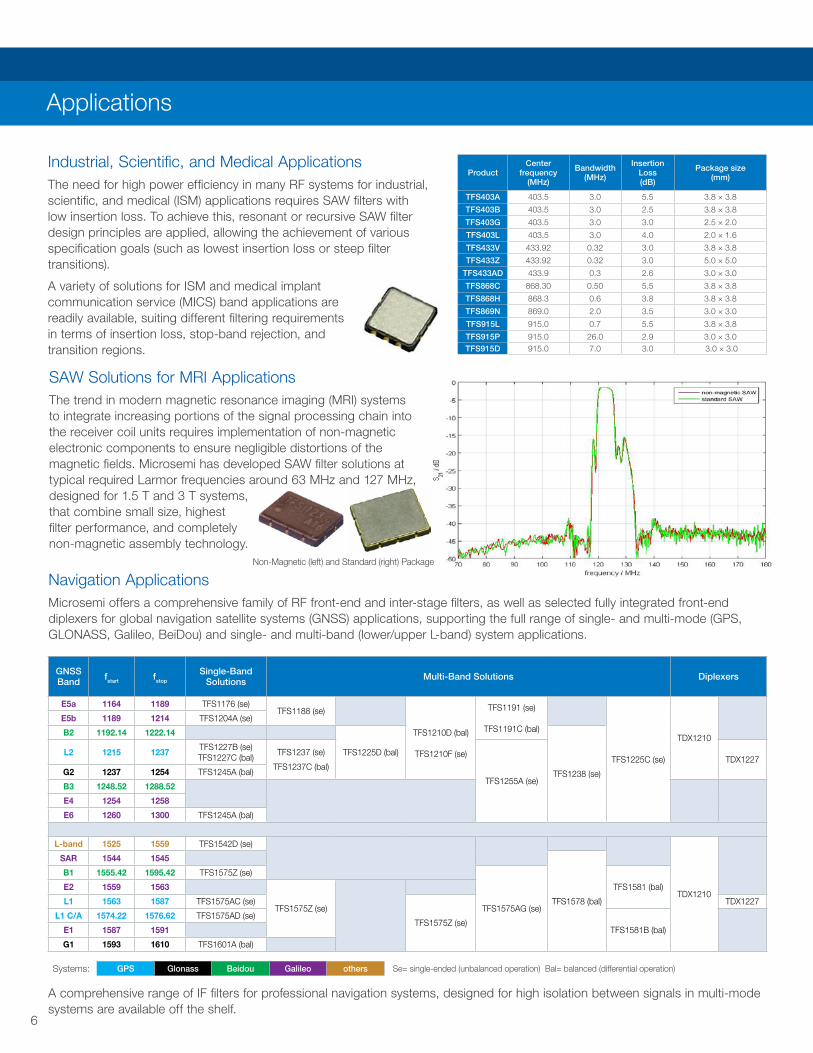
Industrial, Scientific, and Medical Applications The need for high power efficiency in many RF systems for industrial, scientific, and medical (ISM) applications requires SAW filters with low insertion loss. To achieve this, resonant or recursive SAW filter design principles are applied, allowing the achievement of various specification goals (such as lowest insertion loss or steep filter transitions).
A variety of solutions for ISM and medical implant communication service (MICS) band applications are readily available, suiting different filtering requirements in terms of insertion loss, stop-band rejection, and transition regions.
Navigation ApplicationsMicrosemi offers a comprehensive family of RF front-end and inter-stage filters, as well as selected fully integrated front-end diplexers for global navigation satellite systems (GNSS) applications, supporting the full range of single- and multi-mode (GPS, GLONASS, Galileo, BeiDou) and single- and multi-band (lower/upper L-band) system applications.
A comprehensive range of IF filters for professional navigation systems, designed for high isolation between signals in multi-mode systems are available off the shelf.
SAW Solutions for MRI ApplicationsThe trend in modern magnetic resonance imaging (MRI) systems to integrate increasing portions of the signal processing chain into the receiver coil units requires implementation of non-magnetic electronic components to ensure negligible distortions of the magnetic fields. Microsemi has developed SAW filter solutions at typical required Larmor frequencies around 63 MHz and 127 MHz, designed for 1.5 T and 3 T systems, that combine small size, highest filter performance, and completely non-magnetic assembly technology.
ProductCenter
frequency (MHz)
Bandwidth (MHz)
Insertion Loss (dB)
Package size (mm)
TFS403A 403.5 3.0 5.5 3.8 × 3.8
TFS403B 403.5 3.0 2.5 3.8 × 3.8
TFS403G 403.5 3.0 3.0 2.5 × 2.0
TFS403L 403.5 3.0 4.0 2.0 × 1.6
TFS433V 433.92 0.32 3.0 3.8 × 3.8
TFS433Z 433.92 0.32 3.0 5.0 × 5.0
TFS433AD 433.9 0.3 2.6 3.0 × 3.0
TFS868C 868.30 0.50 5.5 3.8 × 3.8
TFS868H 868.3 0.6 3.8 3.8 × 3.8
TFS869N 869.0 2.0 3.5 3.0 × 3.0
TFS915L 915.0 0.7 5.5 3.8 × 3.8
TFS915P 915.0 26.0 2.9 3.0 × 3.0TFS915D 915.0 7.0 3.0 3.0 × 3.0
GNSS Band fstart fstop
Single-Band Solutions Multi-Band Solutions Diplexers
E5a 1164 1189 TFS1176 (se)TFS1188 (se)
TFS1210D (bal)
TFS1210F (se)
TFS1191 (se)
TFS1191C (bal)
TFS1225C (se)
TDX1210
E5b 1189 1214 TFS1204A (se)
B2 1192.14 1222.14
TFS1225D (bal)
TFS1238 (se)
L2 1215 1237TFS1227B (se)TFS1227C (bal)
TFS1237 (se)
TFS1237C (bal)
TFS1255A (se)
TDX1227G2 1237 1254 TFS1245A (bal)
B3 1248.52 1288.52
E4 1254 1258
E6 1260 1300 TFS1245A (bal)
L-band 1525 1559 TFS1542D (se)
TDX1210
SAR 1544 1545
TFS1578 (bal)
B1 1555.42 1595.42 TFS1575Z (se)
TFS1575AG (se)
TFS1581 (bal)E2 1559 1563
TFS1575Z (se)L1 1563 1587 TFS1575AC (se)
TFS1575Z (se)
TDX1227
L1 C/A 1574.22 1576.62 TFS1575AD (se)
TFS1581B (bal)E1 1587 1591
G1 1593 1610 TFS1601A (bal)
Systems: GPS Glonass Beidou Galileo others Se= single-ended (unbalanced operation) Bal= balanced (differential operation)
Non-Magnetic (left) and Standard (right) Package
7
Aerospace and Defense
• Surface-mount, through-hole, and connector-type packages available • Qualification according to MIL-STD-883 and/or pre-defined (for instance, ESCC 3502) or custom space qualification plans • Ruggedized SAW modules with internal matching • High-reliability versions of standard designs available
The aerospace and defense family of Microsemi SAW products offers highest reliability levels for harsh and mission-critical environments. With each application having unique requirements, Microsemi offers not only a wide range of packaging technologies for ruggedized applications, but also the full range of SAW device designs covering a center frequency range from 30 MHz to 2.7 GHz. Our facility in Simsbury, CT can support projects with security concerns such as ITAR, EAR, and classified specifications/hardware.
In addition to multi-layer ceramic and metal can assembly technologies, package designs with integrated matching circuitry in electrically and environmentally isolated cavities offer superior electrical performance in combination with outstanding environmental reliability.
Oscillator and Narrow-Band Filtering ApplicationsMicrosemi offers a unique portfolio of narrow-band, high-Q, and temperature- and aging-stable filters in frequency ranges up to 2.5 GHz, suiting professional and high-reliability requirements for narrow-band filtering or extreme precision SAW-based oscillator applications.
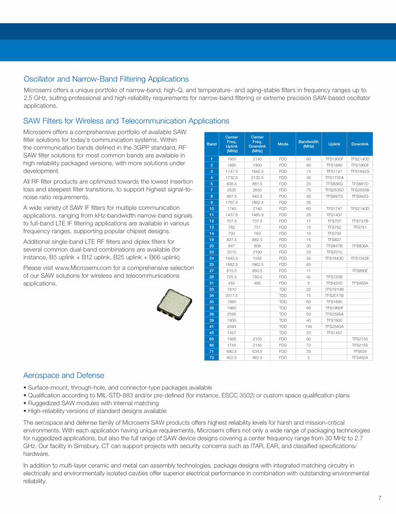
SAW Filters for Wireless and Telecommunication ApplicationsMicrosemi offers a comprehensive portfolio of available SAW filter solutions for today’s communication systems. Within the communication bands defined in the 3GPP standard, RF SAW filter solutions for most common bands are available in high reliability packaged versions, with more solutions under development.
All RF filter products are optimized towards the lowest insertion loss and steepest filter transitions, to support highest signal-to-noise ratio requirements.
A wide variety of SAW IF filters for multiple communication applications, ranging from kHz-bandwidth narrow-band signals to full-band LTE IF filtering applications are available in various frequency ranges, supporting popular chipset designs.
Additional single-band LTE RF filters and diplex filters for several common dual-band combinations are available (for instance, B5 uplink + B12 uplink, B25 uplink + B66 uplink).
Please visit www.Microsemi.com for a comprehensive selection of our SAW solutions for wireless and telecommunications applications.
Systems: GPS Glonass Beidou Galileo others Se= single-ended (unbalanced operation) Bal= balanced (differential operation)
Band
CenterFreq. Uplink (MHz)
Center Freq.
Downlink (MHz)
Mode Bandwidth(MHz) Uplink Downlink
1 1950 2140 FDD 60 TFS1950F TFS2140D
2 1880 1960 FDD 60 TFS1880 TFS1960F
3 1747.5 1842.5 FDD 75 TFS1747 TFS1842G
4 1732.5 2132.5 FDD 45 TFS1732A
5 836.5 881.5 FDD 25 TFS836G TFS881D
7 2535 2655 FDD 70 TFS2535D TFS2655B
8 897.5 942.5 FDD 35 TFS897G TFS942G
9 1767.4 1862.4 FDD 35
10 1740 2140 FDD 60 TFS1747 TFS2140D
11 1437.9 1485.9 FDD 20 TFS1437
12 707.5 737.5 FDD 17 TFS707 TFS737B
13 782 751 FDD 10 TFS782 TFS751
14 793 763 FDD 10 TFS793
19 837.5 882.5 FDD 15 TFS837
20 847 806 FDD 30 TFS847B TFS806A
23 2010 2190 FDD 20 TFS2010
24 1643.5 1542 FDD 34 TFS1643D TFS1542E
25 1882.5 1962.5 FDD 65
27 815.5 860.5 FDD 17 TFS860E
28 725.5 780.5 FDD 45 TFS725B
31 455 465 FDD 5 TFS455D TFS465A
33 1910 TDD 20 TFS1910B
34 2017.5 TDD 15 TFS2017B
35 1880 TDD 60 TFS1880
36 1960 TDD 60 TFS1960F
38 2595 TDD 50 TFS2595A
39 1900 TDD 40 TFS1900
41 2593 TDD 194 TFS2593A
45 1457 TDD 20 TFS1457
65 1965 2155 FDD 90 TFS2155
66 1745 2155 FDD 70 TFS2155
71 680.5 634.5 FDD 35 TFS634
73 452.5 462.5 FDD 5 TFS462A

©2018 Microsemi Corporation. All rights reserved. Microsemi and the Microsemi logo are registered trademarks of Microsemi Corporation. All other trademarks and service marks are the property of their respective owners.
Microsemi makes no warranty, representation, or guarantee regarding the information contained herein or the suitability of its products and services for any particular purpose, nor does Microsemi assume any liability whatsoever arising out of the application or use of any product or circuit. The products sold hereunder and any other products sold by Microsemi have been subject to limited testing and should not be used in conjunction with mission-critical equipment or applications. Any performance specifications are believed to be reliable but are not verified, and Buyer must conduct and complete all performance and other testing of the products, alone and together with, or installed in, any end-products. Buyer shall not rely on any data and performance specifications or parameters provided by Microsemi. It is the Buyer’s responsibility to independently determine suitability of any products and to test and verify the same. The information provided by Microsemi hereunder is provided “as is, where is” and with all faults, and the entire risk associated with such information is entirely with the Buyer. Microsemi does not grant, explicitly or implicitly, to any party any patent rights, licenses, or any other IP rights, whether with regard to such information itself or anything described by such information. Information provided in this document is proprietary to Microsemi, and Microsemi reserves the right to make any changes to the information in this document or to any products and services at any time without notice.
Microsemi Corporation (Nasdaq: MSCC) offers a comprehensive portfolio of semiconductor and system solutions for aerospace & defense, communications, data center and industrial markets. Products include high-performance and radiation-hardened analog mixed-signal integrated circuits, FPGAs, SoCs and ASICs; power management products; timing and synchronization devices and precise time solutions, setting the world’s standard for time; voice processing devices; RF solutions; discrete components; enterprise storage and communication solutions, security technologies and scalable anti-tamper products; Ethernet solutions; Power-over-Ethernet ICs and midspans; as well as custom design capabilities and services. Microsemi is headquartered in Aliso Viejo, California and has approximately 4,800 employees globally. Learn more at www.microsemi.com.
Microsemi Corporate HeadquartersOne Enterprise, Aliso Viejo, CA 92656 USAWithin the USA: +1 (800) 713-4113 Outside the USA: +1 (949) 380-6100 Fax: +1 (949) 215-4996Email: [email protected] www.microsemi.com
SAW-05-18
Microsemi is continually adding new products to its industry-leading portfolio.
For the most recent updates to our product line and for detailed information and specifications, please call, email or visit our website:
Toll-free: 800-713-4113
www.microsemi.com
www.microsemi.com/applications/commercial-aviation
www.microsemi.com/applications/commercial-aviation/aviation-center-of-excellence