voice controlled robot using gripping mechanism
DESCRIPTION
This project enlightens the research and implementation of voice automated mobile robot. The robot is controlled through connected speech input. The language input allows a user to interact with the robot which is familiar to most of the people. The advantages of speech activated robots are hands-free and fast data input operations. In future, it is expected that speech recognition systems will be used as man-machine interface for robots in rehabilitation, entertainment etc. In view of this, aforementioned system is a source of learning process for a mobile robot which takes speech input as commands and performs some navigation task through a distinct man machine interaction with the application of the learning. The speech recognition system is trained in such a way that it recognizes defined commands and the designed robot navigates based on the instruction through the Speech Commands. The medium of interaction between humans and computers is on the processing of speech (words uttered by the person). The complete system consists of three subsystems, the speech recognition system, a central controller and the robot. We have studied the various factors such as noise which interferes during speech recognition and distance factor. The results prove that proposed robot is capable of understanding the meaning of speech commands.TRANSCRIPT
Guru Tegh Bahadur Institute of Technology ANKL Group (ECE)
DESIGN OF VOICE CONTROLLED ROBOT WITH GRIPPER USING AVR
Under the sincere supervision of:
Mr. Mukesh Sahu Mrs. Mamta Rani
Submitted by
Anjani Kumar Singh (11413202809) Kanwaljeet Singh (09213202809) Lovneesh Tanwar (09913202809) Nikhil Aggarwal (13213202809)
In partial fulfillment of the requirement for the award of the degree of
Bachelor of Technology In
Electronics and Communication
Guru Tegh Bahadur Institute of Technology G-8 Area, Rajouri Garden
Affiliated to Guru Gobind Singh Indraprastha University
Delhi
Batch:2009-2013

Guru Tegh Bahadur Institute of Technology ANKL Group (ECE)
ACKNOWLEGDEMENT
We take this opportunity to express our deepest gratitude towards Mr. Mukesh Sahu
and Ms. Mamta Rani, our project guides, who has been the driving force behind this
project and whose guidance and co-operation has been a source of inspiration for us.
We would also like to thank Mr Amrish Maggo and Ms. Parul Dawar for their
valuable support whenever needed.
We are very much thankful to our professors, colleagues and authors of various
publications to which we have been referring to. We express our sincere appreciation
and thanks to all those who have guided us directly or indirectly in our project. Also
much needed moral support and encouragement was provided on numerous occasions
by our whole division.
Finally we thank our parents for their immense support.
Anjani Kumar Nikhil Aggarwal
Kanwaljeet Singh Lovneesh Tanwar

Guru Tegh Bahadur Institute of Technology ANKL Group (ECE)
DECLARATION
This is to certify that the report entitled “Design of Voice Controlled Robot with
Gripping Mechanism using AVR” which is submitted by us in partial fulfillment of
the requirement for the award of the degree of ‘Bachelor of Technology in Electronics
and Communication Engineering‘ from Guru Tegh Bahadur Institute of Technology,
New Delhi is comprising of our original work and due acknowlegdement has been
made in text to all my other materials used under the supervision of our project
guides.
Anjani Kumar Nikhil Aggarwal
Kanwaljeet Singh Lovneesh Tanwar

Guru Tegh Bahadur Institute of Technology ANKL Group (ECE)
CERTIFICATION
This is to certify that the Minor Project Report entitled “Design of Voice Controlled
Robot with Gripping Mechanism using AVR” submitted in partial fulfillment of the
requirement for the degree of Bachelor of Technology in Electronics and
Communication Engineering is a bona fide research work carried out by Anjani
kumar, Nikhil Aggarwal, Kanwaljeet Singh & Lovneesh Tanwar, students of the
“Guru Tegh Bahadur Institute of Technology” affiliated to Guru Gobind Singh
Indraprastha University, Delhi under our supervision.This has not been submitted to
any other University or Institution for the award of any degree/diploma/certificate.
Mukesh Sahu Mamta Rani (Project Guide) (Project Guide) Amrish Maggo Parul Dawar (Project Coordinator) (Project Coordinator) Amrik Singh Vaneet Singh (Head Project Coordinator) (H.O.D., ECE)

Guru Tegh Bahadur Institute of Technology ANKL Group (ECE)
ABSTRACT
This project enlightens the research and implementation of voice automated mobile robot.
The robot is controlled through connected speech input. The language input allows a user to
interact with the robot which is familiar to most of the people. The advantages of speech
activated robots are hands-free and fast data input operations. In future, it is expected that
speech recognition systems will be used as man-machine interface for robots in rehabilitation,
entertainment etc. In view of this, aforementioned system is a source of learning process for a
mobile robot which takes speech input as commands and performs some navigation task
through a distinct man machine interaction with the application of the learning. The speech
recognition system is trained in such a way that it recognizes defined commands and the
designed robot navigates based on the instruction through the Speech Commands. The
medium of interaction between humans and computers is on the processing of speech (words
uttered by the person). The complete system consists of three subsystems, the speech
recognition system, a central controller and the robot. We have studied the various factors
such as noise which interferes during speech recognition and distance factor. The results
prove that proposed robot is capable of understanding the meaning of speech commands.
Guru Tegh Bahadur Institute of Technology ANKL Group (ECE)
CONTENTS
1. INTRODUCTION 1-9 1.1. Overview 1.2. Voice Recognition System 1.3. Modules of Project
2. VOICE RECOGNITION MODULE 10-17 2.1. Schematic of the Module 2.2. About HM2007 IC 2.3. Specifications 2.4. Functional Description 2.5. Manual Mode Description 2.6. HY6264 CMOS SRAM 2.7. Working of the Module
3. MICROCONTROLLER MODULE 18-20 3.1. Pin Description
4. TRAINER MODULES 21-23 4.1. Keypad Matrix 4.2. Seven Segment Display Module
5. MOTOR CONTROLLING MODULE 24-25 5.1. DC Motor 5.2. Control with MCUs
6. OTHER MODULES 26-27 6.1. Power Supply Module
7. WORKING FLOW OF PROJECT 28-29 Steps to train and move the robot
8. SOFTWARE DEVELOPMENT 30-35 8.1. Using AVR Studio 4 8.2. Flowchart
9. DIFFICULTIES FACED DURING THE PREPARATION 36-37 Phases of the project
10. APPLICATIONS 38 Appilications and Future aspects
11. CONCLUSION 39
12. APPENDICES 40-66 Appendix I: Block Diagram of the Project Appendix II: Schematics Appendix III: Flowchart for Programming MCU Appendix IV: Source Code Appendix V: Datasheets
13. REFERENCES 67-68
Guru Tegh Bahadur Institute of Technology ANKL Group (ECE)
LIST OF FIGURES
Title Page No
1.1 Overview 1
1.2 Speech Recognition Module 5
1.3 Keypad Matrix Module 6
1.4 Display Module 7
1.5 Motor Driver Module 8
1.6 Power Supply Module 8
1.7 Microcontroller Module 9
2.1 HM2007 Module 10
2.2 Schematic of Speech Recognition Module 11
2.3 Pin Discription of HM2007 IC 12
2.4 Keypad 14
2.5 HY6264 IC 16
2.6 Working of HM2007 17
3.1 Microcontroller Module 18
4.1 Keypad Matrix Circuit 21
4.2 Seven Segment Display Module 22
4.3 Logic Diagram of 74LS373 23
5.1 Motor Driver Module 24
5.2 Motor Driver Circuit 25
6.1 Power Supply 26
6.2 Gripper 27
8.1 Create a New Project 30
8.2 Specifing Project Name and Path 31
8.3 Select Debug Platform & Microcontroller 31
8.4 Configure Project Setting 32
8.5 Flow Chart 36
Guru Tegh Bahadur Institute of Technology
ANKL Group (ECE) 1
CHAPTER 1: INTRODUCTION
1.1 OVERVIEW
The purpose of this project is to build a robotic car which could be controlled using voice commands.
Generally these kinds of systems are known as Speech Controlled Automation Systems (SCAS). Our
system will be a prototype of the same.
We are not aiming to build a robot which can recognize a lot of words. Our basic idea is to develop some
sort of menu driven control for our robot, where the menu is going to be voice driven.
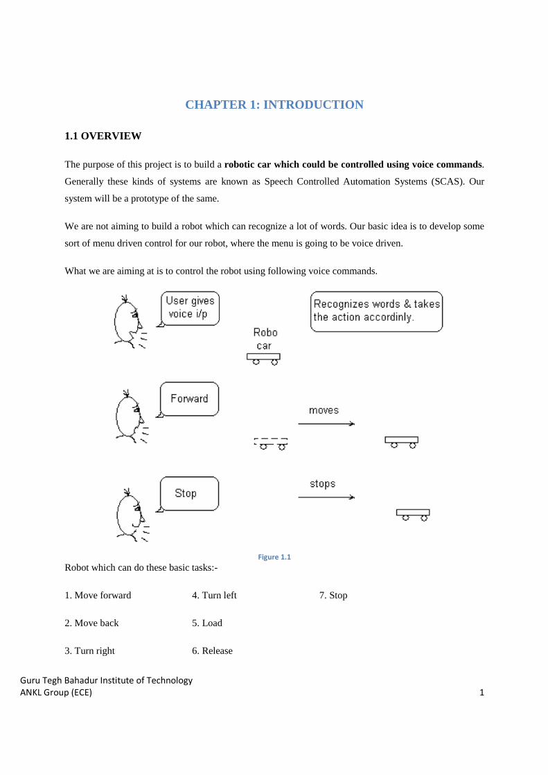
What we are aiming at is to control the robot using following voice commands.
Figure 1.1 Robot which can do these basic tasks:-
1. Move forward 4. Turn left 7. Stop
2. Move back 5. Load
3. Turn right 6. Release

Guru Tegh Bahadur Institute of Technology
ANKL Group (ECE) 2
1.2 VOICE RECOGNITION SYSTEM
When we say voice control, the first term to be considered is Speech Recognition i.e. making the system to
understand human voice. Speech recognition is a technology where the system understands the words
(not its meaning) given through speech.
Speech is an ideal method for robotic control and communication. The speech recognition circuit we will
outline, functions independently from the robot’s main intelligence [central processing unit (CPU)]. This
is a good thing because it doesn’t take any of the robot’s main CPU processing power for word
recognition.
The CPU must merely poll the speech circuit’s recognition lines occasionally to check if a command has
been issued to the robot. We can even improve upon this by connecting the recognition line to one of the
robot’s CPU interrupt lines. By doing this, a recognized word would cause an interrupt, letting the CPU
know a recognized word had been spoken. The advantage of using an interrupt is that polling the circuit’s
recognition line occasionally would no longer be necessary, further reducing any CPU overhead.
Another advantage to this stand-alone speech-recognition circuit (SRC) is its programmability. You can
program and train the SRC to recognize the unique words you want recognized. The SRC can be easily
interfaced to the robot’s CPU.
To control and command an appliance (computer, VCR, TV security system, etc.) by speaking to it, will
make it easier, while increasing the efficiency and effectiveness of working with that device. At its most
basic level speech recognition allows the user to perform parallel tasks, (i.e. hands and eyes are busy
elsewhere) while continuing to work with the computer or appliance. Robotics is an evolving technology.
Suppose you want to control a menu driven system. What is the most striking property that you can think
of? Well the first thought that came to our mind is that the range of inputs in a menu driven system is
limited. In fact, by using a menu all we are doing is limiting the input domain space. Now, this is one
characteristic which can be very useful in implementing the menu in stand-alone systems. For example
think of the pine menu or a washing machine menu. How many distinct commands do they require?
Voice enabled devices basically use the principal of speech recognition. It is the process of electronically
converting a speech waveform (as the realization of a linguistic expression) into words (as a best-decoded
sequence of linguistic units).
Converting a speech waveform into a sequence of words involves several essential steps:
Guru Tegh Bahadur Institute of Technology
ANKL Group (ECE) 3
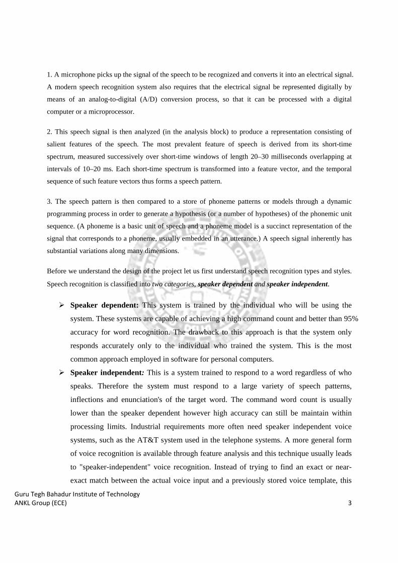
1. A microphone picks up the signal of the speech to be recognized and converts it into an electrical signal.
A modern speech recognition system also requires that the electrical signal be represented digitally by
means of an analog-to-digital (A/D) conversion process, so that it can be processed with a digital
computer or a microprocessor.
2. This speech signal is then analyzed (in the analysis block) to produce a representation consisting of
salient features of the speech. The most prevalent feature of speech is derived from its short-time
spectrum, measured successively over short-time windows of length 20–30 milliseconds overlapping at
intervals of 10–20 ms. Each short-time spectrum is transformed into a feature vector, and the temporal
sequence of such feature vectors thus forms a speech pattern.
3. The speech pattern is then compared to a store of phoneme patterns or models through a dynamic
programming process in order to generate a hypothesis (or a number of hypotheses) of the phonemic unit
sequence. (A phoneme is a basic unit of speech and a phoneme model is a succinct representation of the
signal that corresponds to a phoneme, usually embedded in an utterance.) A speech signal inherently has
substantial variations along many dimensions.
Before we understand the design of the project let us first understand speech recognition types and styles.
Speech recognition is classified into two categories, speaker dependent and speaker independent.
� Speaker dependent: This system is trained by the individual who will be using the
system. These systems are capable of achieving a high command count and better than 95%
accuracy for word recognition. The drawback to this approach is that the system only
responds accurately only to the individual who trained the system. This is the most
common approach employed in software for personal computers.
� Speaker independent: This is a system trained to respond to a word regardless of who
speaks. Therefore the system must respond to a large variety of speech patterns,
inflections and enunciation's of the target word. The command word count is usually
lower than the speaker dependent however high accuracy can still be maintain within
processing limits. Industrial requirements more often need speaker independent voice
systems, such as the AT&T system used in the telephone systems. A more general form
of voice recognition is available through feature analysis and this technique usually leads
to "speaker-independent" voice recognition. Instead of trying to find an exact or near-
exact match between the actual voice input and a previously stored voice template, this

Guru Tegh Bahadur Institute of Technology
ANKL Group (ECE) 4
method first processes the voice input using "Fourier transforms" or "linear predictive
coding (LPC)", then attempts to find characteristic similarities between the expected
inputs and the actual digitized voice input. These similarities will be present for a wide
range of speakers, and so the system need not be trained by each new user. The types of
speech differences that the speaker-independent method can deal with, but which pattern
matching would fail to handle, include accents, and varying speed of delivery, pitch,
volume, and inflection. Speaker-independent speech recognition has proven to be very
difficult, with some of the greatest hurdles being the variety of accents and inflections
used by speakers of different nationalities. Recognition accuracy for speaker independent
systems is somewhat less than for speaker-dependent systems, usually between 90 and 95
percent. Speaker independent systems do not ask to train the system as an advantage, but
perform with lower quality.
� Recognition Style:
Speech recognition systems have another constraint concerning the style of speech they can recognize.
They are three styles of speech: isolated, connected and continuous.
Isolated speech recognition systems can just handle words that are spoken separately. This is the most
common speech recognition systems available today. The user must pause between each word or
command spoken. The speech recognition circuit is set up to identify isolated words of .96 second lengths.
Connected is a half-way point between isolated word and continuous speech recognition. Allows users
to speak multiple words. The HM2007 can be set up to identify words or phrases 1.92 seconds in length.
This reduces the word recognition vocabulary number to 20.
Continuous is the natural conversational speech we are used to in everyday life. It is extremely difficult
for a recognizer to shift through the text as the words tend to merge together. For instance, "Hi, how are
you doing?" sounds like "Hi,.howyadoin" Continuous speech recognition systems are on the market and
are under continual development.

Guru Tegh Bahadur Institute of Technology
ANKL Group (ECE) 5
1.3 MODULES OF PROJECT
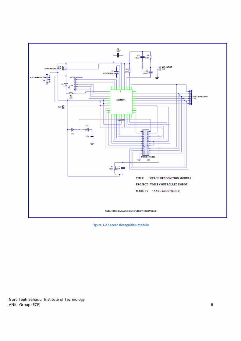
1. VOICE RECOGNITION MODULE: This module basically consists of HM2007L, SRAM (8K*8),
MIC input and a Keypad(4*3). It is the heart of the entire system. HM2007 is a voice recognition chip
with on-chip analog front end, voice analysis, recognition process and system control functions. The
input voice command is analyzed, processed, recognized and then obtained at one of its output port of
microcontroller which is then decoded , amplified and given to motors of robot car. SRAM is
basically used to store the commands for future comparison. Keypad is used to configure HM2007 by
telling at which number a command(word) to be stored in RAM.
Guru Tegh Bahadur Institute of Technology
ANKL Group (ECE) 6
Figure 1.2 Speech Recognition Module

Guru Tegh Bahadur Institute of Technology
ANKL Group (ECE) 7
Figure 1.3 Keypad Matrix Module
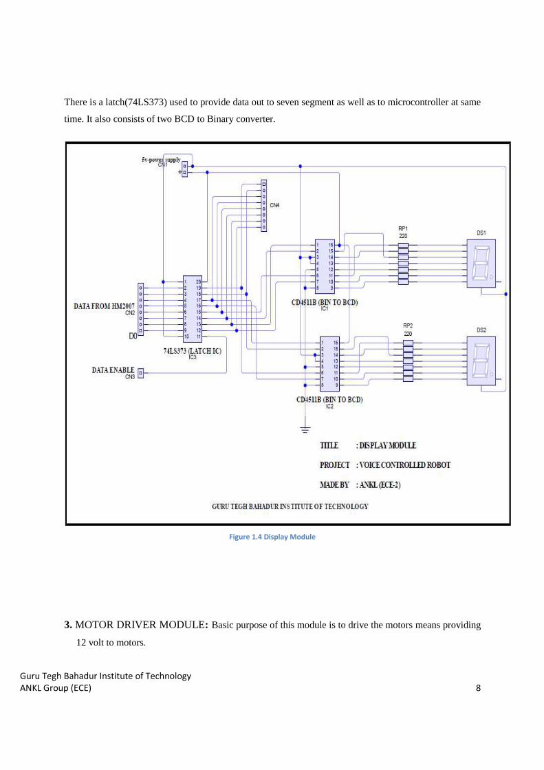
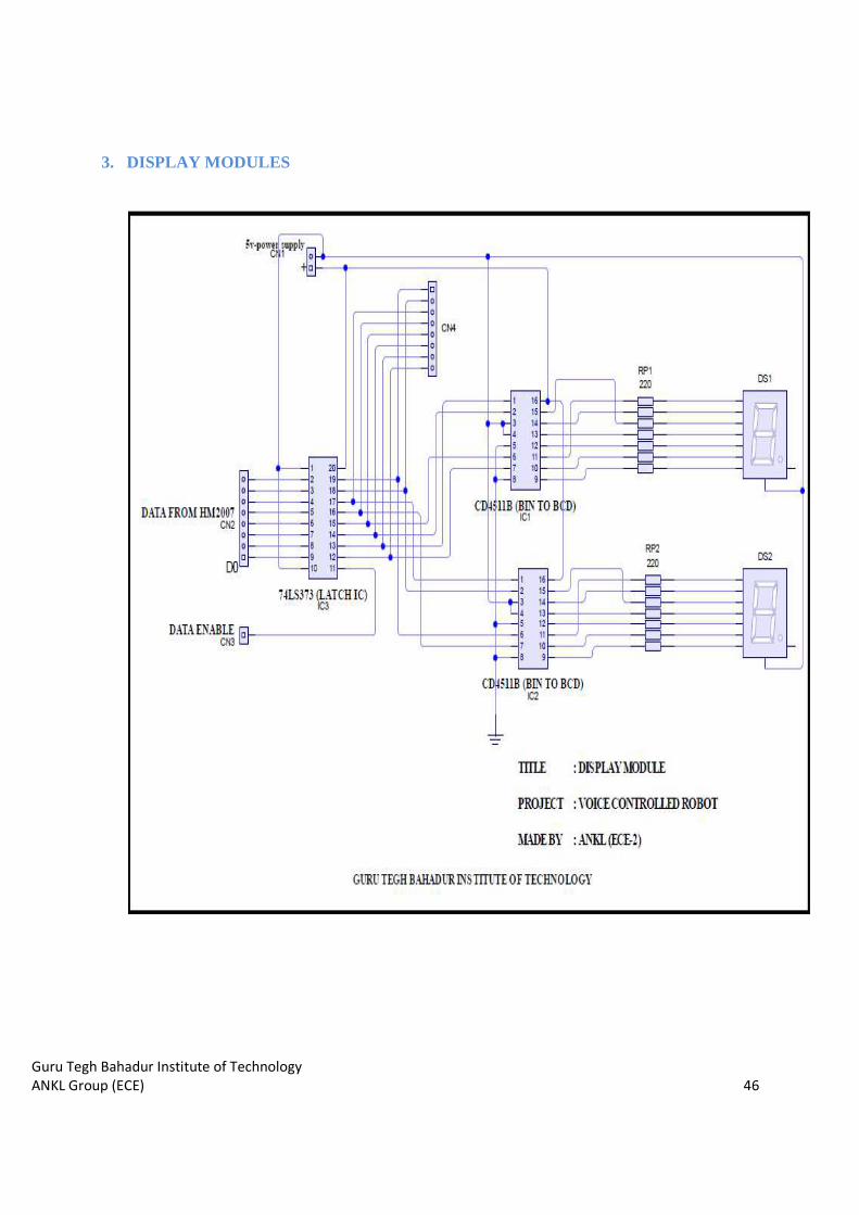
2. DISPLAY MODULE: This module is made to display numbers corresponding to commands stored
for specific tasks to be done by microcontroller. It consists of 2 seven segment which is used as display.
Guru Tegh Bahadur Institute of Technology
ANKL Group (ECE) 8
There is a latch(74LS373) used to provide data out to seven segment as well as to microcontroller at same
time. It also consists of two BCD to Binary converter.
Figure 1.4 Display Module
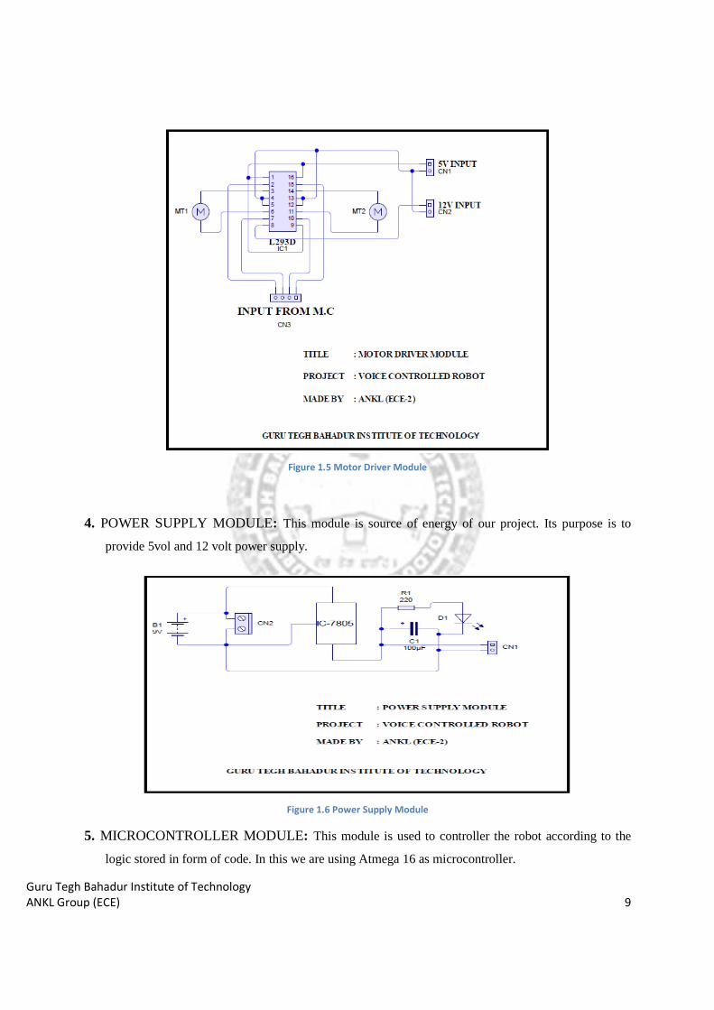
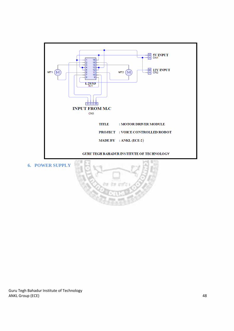
3. MOTOR DRIVER MODULE: Basic purpose of this module is to drive the motors means providing
12 volt to motors.
Guru Tegh Bahadur Institute of Technology
ANKL Group (ECE) 9
Figure 1.5 Motor Driver Module
4. POWER SUPPLY MODULE: This module is source of energy of our project. Its purpose is to
provide 5vol and 12 volt power supply.
Figure 1.6 Power Supply Module
5. MICROCONTROLLER MODULE: This module is used to controller the robot according to the
logic stored in form of code. In this we are using Atmega 16 as microcontroller.
Guru Tegh Bahadur Institute of Technology
ANKL Group (ECE) 10
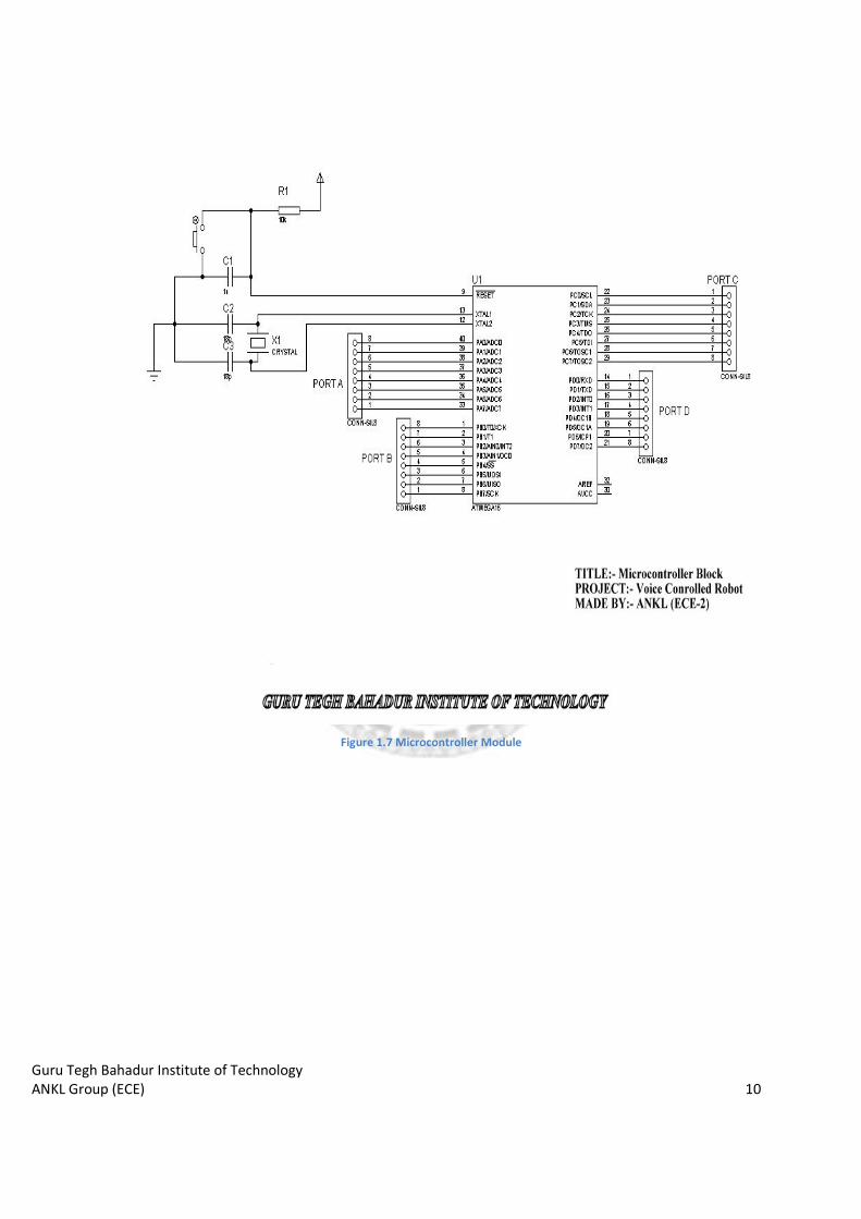
Figure 1.7 Microcontroller Module
Guru Tegh Bahadur Institute of Technology
ANKL Group (ECE) 11
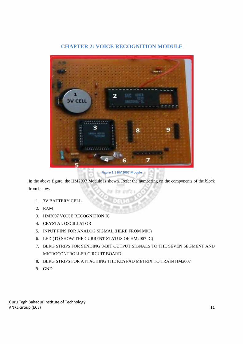
CHAPTER 2: VOICE RECOGNITION MODULE
Figure 2.1 HM2007 Module In the above figure, the HM2007 Module is shown. Refer the numbering on the components of the block
from below.
1. 3V BATTERY CELL
2. RAM
3. HM2007 VOICE RECOGNITION IC
4. CRYSTAL OSCILLATOR
5. INPUT PINS FOR ANALOG SIGMAL (HERE FROM MIC)
6. LED (TO SHOW THE CURRENT STATUS OF HM2007 IC)
7. BERG STRIPS FOR SENDING 8-BIT OUTPUT SIGNALS TO THE SEVEN SEGMENT AND
MICROCONTROLLER CIRCUIT BOARD.
8. BERG STRIPS FOR ATTACHING THE KEYPAD METRIX TO TRAIN HM2007
9. GND

Guru Tegh Bahadur Institute of Technology
ANKL Group (ECE) 12
2.1 SCHEMATIC OF THE MODULE
Figure 2.2 Schematic of Speech Recognition Module
Guru Tegh Bahadur Institute of Technology
ANKL Group (ECE) 13
2.2 ABOUT HM2007 IC
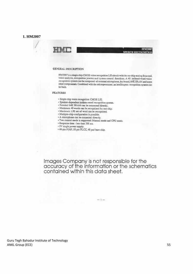
HM2007 is a single chip CMOS voice recognition LSI circuit with on-chip analog front end voice
analysis, recognition process and system control functions. A 40 isolated-word voice recognition system
can be composed of external microphone, keyboard, 64K SRAM and some other components. Combined
with the microprocessor, an intelligent recognition system can be built.
SOME OF THE FEATURES OF THE IC:
• Single chip voice recognition CMOS LSI.
• Speaker-dependent isolates-word recognition system.
• External 64K SRAM can be connected directly.
• Maximum 40 words (1 second each) and 20 words (1.92 second each) can be easily recognized.
• Maximum 1.92 second long word can be recognized.
• Multiple-chip configuration is possible.
• A microphone can be connected directly.
• Two control modes are supported: Manual mode and CPU mode.
• Response time: less than 300 milliseconds.
• 5V single power supply.
• 48-pin DIP, 52-pin PLCC, 48-pad bare chip packages are available.
Guru Tegh Bahadur Institute of Technology
ANKL Group (ECE)
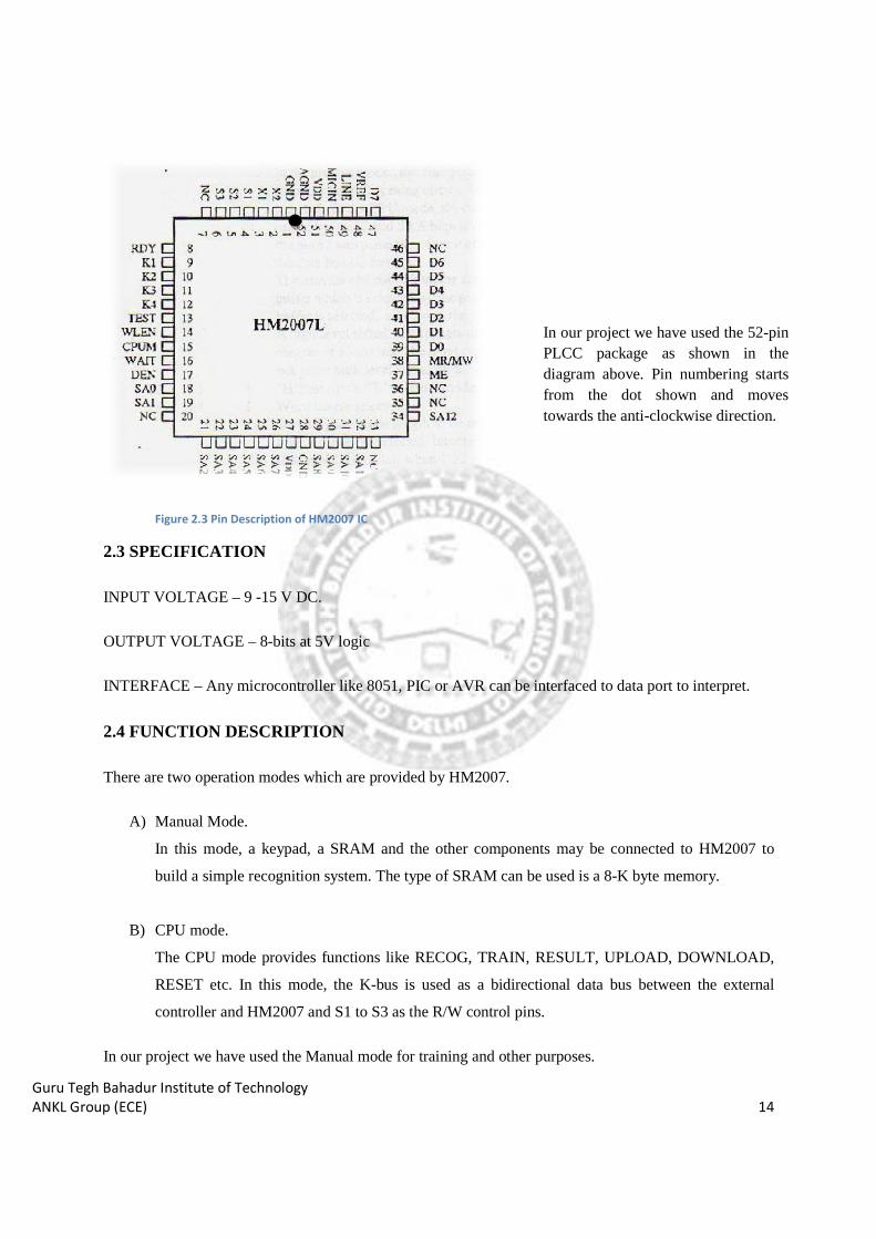
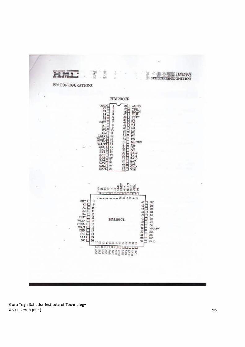
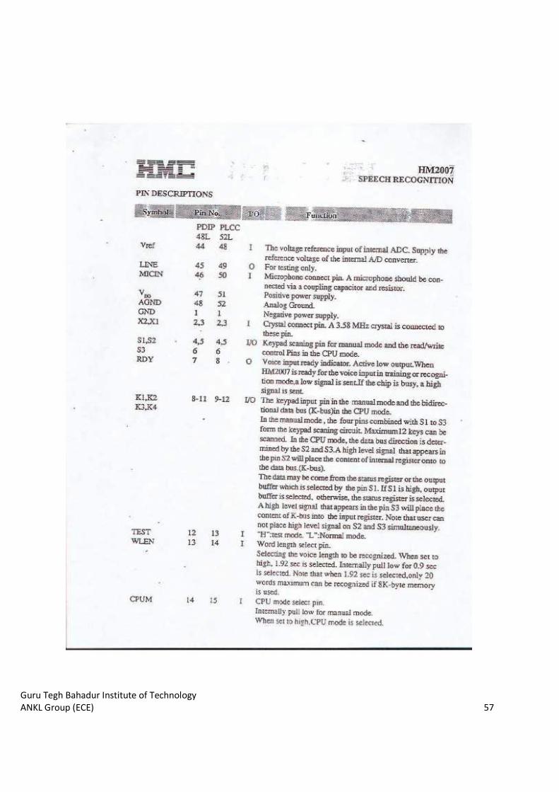
Figure 2.3 Pin Description of HM
2.3 SPECIFICATION
INPUT VOLTAGE – 9 -15 V DC.
OUTPUT VOLTAGE – 8-bits at 5V logic
INTERFACE – Any microcontroller like 8051, PIC or AVR can be interfaced to data port to interpret.
2.4 FUNCTION DESCRIPTION
There are two operation modes which are provided by HM2007.
A) Manual Mode.
In this mode, a keypad, a SRAM and the other components ma
build a simple recognition system. The type of SRAM can be used is a 8
B) CPU mode.
The CPU mode provides functions like RECOG, TRAIN, RESULT, UPLOAD, DOWNLOAD,
RESET etc. In this mode, the K
controller and HM2007 and S1 to S3 as the R/W control pins.
In our project we have used the Manual mode for training and other purposes.
2.3 Pin Description of HM2007 IC
15 V DC.
bits at 5V logic
Any microcontroller like 8051, PIC or AVR can be interfaced to data port to interpret.
FUNCTION DESCRIPTION
There are two operation modes which are provided by HM2007.
In this mode, a keypad, a SRAM and the other components may be connected to HM2007 to
build a simple recognition system. The type of SRAM can be used is a 8-
The CPU mode provides functions like RECOG, TRAIN, RESULT, UPLOAD, DOWNLOAD,
RESET etc. In this mode, the K-bus is used as a bidirectional data bus between the external
controller and HM2007 and S1 to S3 as the R/W control pins.
In our project we have used the Manual mode for training and other purposes.
In our project we have used the 52PLCC package as showndiagram above. Pin numbering starts from the dot shown and moves towards the anti
14
Any microcontroller like 8051, PIC or AVR can be interfaced to data port to interpret.
y be connected to HM2007 to
-K byte memory.
The CPU mode provides functions like RECOG, TRAIN, RESULT, UPLOAD, DOWNLOAD,
ectional data bus between the external
In our project we have used the 52-pin PLCC package as shown in the diagram above. Pin numbering starts from the dot shown and moves towards the anti-clockwise direction.

Guru Tegh Bahadur Institute of Technology
ANKL Group (ECE) 15
2.5 MANUAL MODE DESCRIPTION
There are four stages of manual mode which take place sequentially after the circuit is ON.
A) Power ON
When the power is ON HM2007 will start its initialization process. If wait pin is LOW, HM2007
will do the memory check to see whether the external 8K byte SRAM is perfect or not.
If WAIT pin is HIGH, HM2007 will skip the memory check process. After the initial process is
done, HM2007 will then move into recognition mode.
B) RECOGNITION MODE
1. WAIT pin is “HIGH”:
In this mode, the RDY is set to LOW and HM2007 is ready to accept the voice input to be
recognized. When the voice input is detected, the RDY will return to HIGH and HM2007 begin
its recognition process. It is recommended that user train the word pattern before the beginning of
the recognition operation, otherwise the result will be unpredictable. After the recognition process
is completely, the result will appear on the D-Bus with the DEN active.
2. WAIT pin is “LOW”:
In this mode, no voice input is accepted until WAIT pin back to HIGH state.
C) TRAINING OR CLEARING ONE PATTERN
Two operations are included during this time,
1. Clearing trained pattern and 2. Training new pattern.
To clear or train the voice pattern, one must select the word number to process first. The number
of word is composed of two digits. The two digits are entered into HM2007 through the keypad
one digit at a time. If more than two digits are entered, only the last two digits are valid. When
key is pressed, the number of key will be echoed to the D-Bus.
Guru Tegh Bahadur Institute of Technology
ANKL Group (ECE)
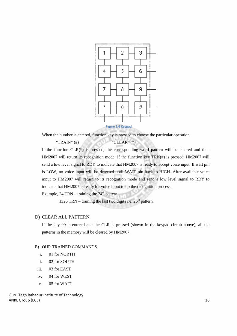
When the number is entered, function key is pressed to choose the particular operation.
“TRAIN” (#)
If the function CLR(*)
HM2007 will return its recognition mode. If the function key TRN
send a low level signal to RDY to indicate that HM2007 is ready to accept voice input. If wait pin
is LOW, no voice input will be detected
input to HM2007 will return to its recognition mode and send a low level signal to RDY to
indicate that HM2007 is ready for voice input to do the recognition process.
Example, 24 TRN – training the 24
1326 TRN – training the last two digits i.e. 26
D) CLEAR ALL PATTERN
If the key 99 is entered and the CLR is pressed (shown in the keypad circuit above), all the
patterns in the memory will be cleared by HM2007.
E) OUR TRAINED COMMANDS
i. 01 for NORTH
ii. 02 for SOUTH
iii. 03 for EAST
iv. 04 for WEST
v. 05 for WAIT
Figure 2.4 Keypad
When the number is entered, function key is pressed to choose the particular operation.
“CLEAR” (*)
(*) is pressed, the corresponding word pattern will be cleared and then
HM2007 will return its recognition mode. If the function key TRN(#) is pressed, HM2007 will
send a low level signal to RDY to indicate that HM2007 is ready to accept voice input. If wait pin
is LOW, no voice input will be detected until WAIT pin back to HIGH. After available voice
input to HM2007 will return to its recognition mode and send a low level signal to RDY to
indicate that HM2007 is ready for voice input to do the recognition process.
training the 24th pattern.
training the last two digits i.e. 26th pattern.
CLEAR ALL PATTERN
If the key 99 is entered and the CLR is pressed (shown in the keypad circuit above), all the
patterns in the memory will be cleared by HM2007.
OUR TRAINED COMMANDS
16
When the number is entered, function key is pressed to choose the particular operation.
will be cleared and then
is pressed, HM2007 will
send a low level signal to RDY to indicate that HM2007 is ready to accept voice input. If wait pin
until WAIT pin back to HIGH. After available voice
input to HM2007 will return to its recognition mode and send a low level signal to RDY to
indicate that HM2007 is ready for voice input to do the recognition process.
If the key 99 is entered and the CLR is pressed (shown in the keypad circuit above), all the
Guru Tegh Bahadur Institute of Technology
ANKL Group (ECE) 17
vi. 06 for HOLD
vii. 07 for DROP
F) ERROR CODES
The chip provides the following error codes.
55 for WORD TOO LONG
66 for WORD TOO SHORT
77 for NO MATCH FOUND
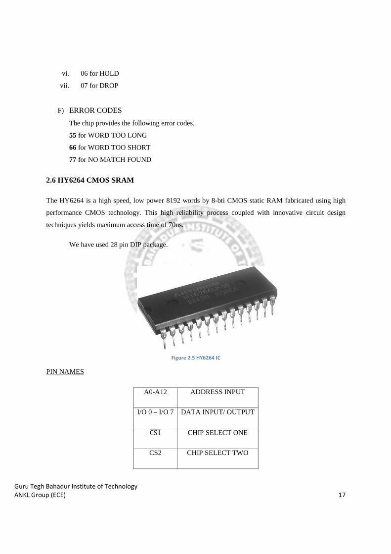
2.6 HY6264 CMOS SRAM
The HY6264 is a high speed, low power 8192 words by 8-bti CMOS static RAM fabricated using high
performance CMOS technology. This high reliability process coupled with innovative circuit design
techniques yields maximum access time of 70ns.
We have used 28 pin DIP package.
Figure 2.5 HY6264 IC
PIN NAMES
A0-A12 ADDRESS INPUT
I/O 0 – I/O 7 DATA INPUT/ OUTPUT
CS1����� CHIP SELECT ONE
CS2 CHIP SELECT TWO

Guru Tegh Bahadur Institute of Technology
ANKL Group (ECE) 18
WE����� WRITE ENABLE
OE���� OUTPUT ENABLE
�CC POWER
GND GROUND
SRAM is using 3V supply for its operation.
SRAM is sharing its 12 bit address bus with the HM2007’s 12 bit address bus. This is because at the time
of operation the HM2007 checks the RAM for the words stored corresponding to the input voice signal.
Without SRAM the HM2007 will not store any commands for them after training the HM2007 IC.
SRAM has 8 bit output (D0 – D7)which is connected to 8 bit output of HM2007 and the latch IC of seven
segment module.
2.7 WORKING OF THE MODULE
We are considering the working of the module after we have already trained the HM2007. HM2007 takes
the input from 4 rows and 3 columns of the keypad matrix to the SI, S2, S3 and K1, K2, K3, K4 pins
respectively of the HM2007. For each command we speak, HM2007 generates a unique 8-bit output on
D0 – D7 pins. These 8-bit signals are also stored in the SRAM’s D0 – D7 pins for accessing them in
future when required. This 8-bit output is transferred to LATCH IC 74LS373 which drives the further
circuit of the seven segment module. With the help of this 8-bit output generated, we control the
Microcontroller block for driving the motors.
SRAM
HM2007 Voice input signal 7 segment
module
Microcontroller
module
Motor driver
module
12-bit address lines 8-bit data lines
8-bit signal
Motor control signals
Guru Tegh Bahadur Institute of Technology
ANKL Group (ECE) 19
CHAPTER 3: MICROCONTROLLER MODULE
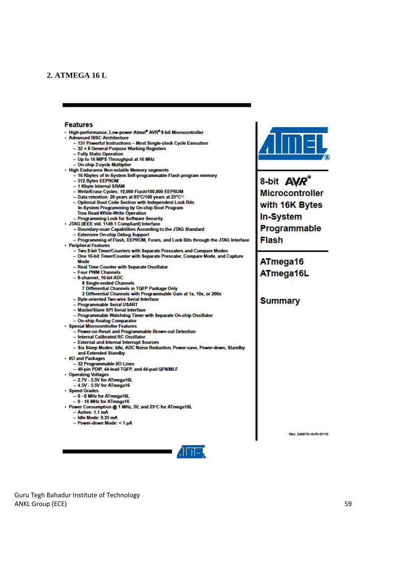
The ATmega16 is a low-power CMOS 8-bit microcontroller based on the AVR enhanced RISC
architecture. By executing powerful instructions in a single clock cycle, the ATmega16 achieves
throughputs approaching 1 MIPS per MHz allowing the system designed to optimize power consumption
versus processing speed.
The Flash Program memory can be reprogrammed In-System through an SPI serial interface, by a
conventional non-volatile memory programmer, or by an On-chip boot program running on the AVR core.
The boot program can use any interface to download the application program in the Application Flash
memory. Software in the Boot Flash Section will continue to run while the Application Flash Section is
updated, providing true Read-While-Write operation. By combining an 8-bit RISC CPU with In-System
Self-Programmable Flash on a monolithic chip, the Atmel ATmega16 is a powerful microcontroller that
provides a highly-flexible and cost-effective solution to many embedded control applications.
Figure 2.6 Working of HM2007
Guru Tegh Bahadur Institute of Technology
ANKL Group (ECE) 20
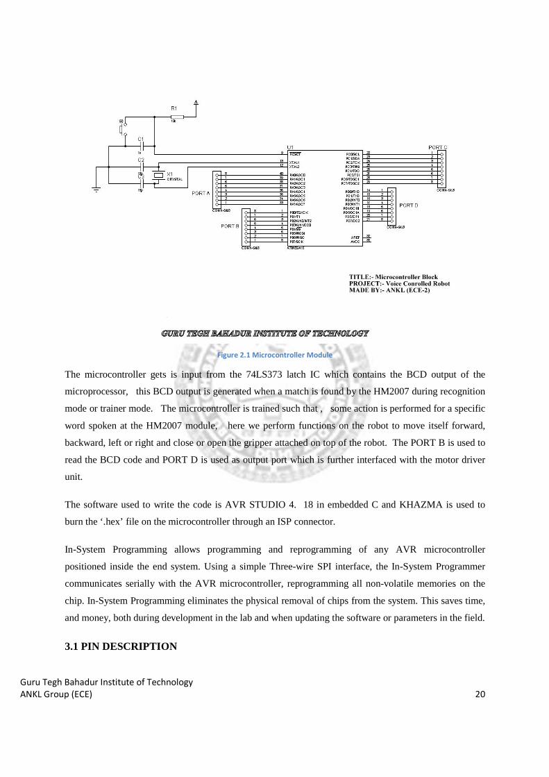
Figure 2.1 Microcontroller Module
The microcontroller gets is input from the 74LS373 latch IC which contains the BCD output of the
microprocessor, this BCD output is generated when a match is found by the HM2007 during recognition
mode or trainer mode. The microcontroller is trained such that , some action is performed for a specific
word spoken at the HM2007 module, here we perform functions on the robot to move itself forward,
backward, left or right and close or open the gripper attached on top of the robot. The PORT B is used to
read the BCD code and PORT D is used as output port which is further interfaced with the motor driver
unit.
The software used to write the code is AVR STUDIO 4. 18 in embedded C and KHAZMA is used to
burn the ‘.hex’ file on the microcontroller through an ISP connector.
In-System Programming allows programming and reprogramming of any AVR microcontroller
positioned inside the end system. Using a simple Three-wire SPI interface, the In-System Programmer
communicates serially with the AVR microcontroller, reprogramming all non-volatile memories on the
chip. In-System Programming eliminates the physical removal of chips from the system. This saves time,
and money, both during development in the lab and when updating the software or parameters in the field.
3.1 PIN DESCRIPTION

Guru Tegh Bahadur Institute of Technology
ANKL Group (ECE) 21
VCC Digital supply voltage.
GND Ground.
Port A (PA7..PA0) Port A serves as the analog inputs to the A/D Converter. Port A also serves as an 8-
bit bi-directional I/O port, if the A/D Converter is not used. Port pins can provide internal pull-up resistors
(selected for each bit). The Port A output buffers have symmetrical drive characteristics with both high
sink and source capability. When pins PA0 to PA7 are used as inputs and are externally pulled low, they
will source current if the internal pull-up resistors are activated. The Port A pins are tri-stated when a
reset condition becomes active, even if the clock is not running.
Port B (PB7..PB0) Port B is an 8-bit bi-directional I/O port with internal pull-up resistors (selected for
each bit). The Port B output buffers have symmetrical drive characteristics with both high sink and source
capability. As inputs, Port B pins that are externally pulled low will source current if the pull-up resistors
are activated. The Port B pins are tri-stated when a reset condition becomes active, even if the clock is not
running.
Port C (PC7..PC0) Port C is an 8-bit bi-directional I/O port with internal pull-up resistors (selected for
each bit). The Port C output buffers have symmetrical drive characteristics with both high sink and source
capability. As inputs, Port C pins that are externally pulled low will source current if the pull-up resistors
are activated. The Port C pins are tri-stated when a reset condition becomes active, even if the clock is not
running. If the JTAG interface is enabled, the pull-up resistors on pins PC5(TDI), PC3(TMS) and
PC2(TCK) will be activated even if a reset occurs.
Port D (PD7..PD0) Port D is an 8-bit bi-directional I/O port with internal pull-up resistors (selected for
each bit). The Port D output buffers have symmetrical drive characteristics with both high sink and source
capability. As inputs, Port D pins that are externally pulled low will source current if the pull-up resistors
are activated. The Port D pins are tri-stated when a reset condition becomes active, even if the clock is not
running.
RESET Input. A low level on this pin for longer than the minimum pulse length will generate a reset,
even if the clock is not running. Shorter pulses are not guaranteed to generate a reset.
XTAL1 Input to the inverting Oscillator amplifier and input to the internal clock operating circuit.
XTAL2 Output from the inverting Oscillator amplifier.
Guru Tegh Bahadur Institute of Technology
ANKL Group (ECE) 22
AVCC is the supply voltage pin for Port A and the A/D Converter. It should be externally connected to
VCC, even if the ADC is not used. If the ADC is used, it should be connected to VCC through a low-pass
filter.
AREF is the analog reference pin for the A/D Converter.
CHAPTER 4: TRAINER MODULES
4.1 KEYPAD MATRIX
There are many methods depending on how you connect your keypad with your controller, but the basic
logic is same. We make the columns as i/p and we drive the rows making them o/p, this whole procedure
of reading the keyboard is called scanning.
In order to detect which key is pressed from the matrix, we make row lines low one by one and read the
columns. Let’s say we first make Row1 low, and then read the columns. If any of the key in row1 is
pressed, it will make the corresponding column as low, i.e. if second key is pressed in Row1, then
column2 will be low. So we come to know that key 2 of Row1 is pressed. This is how scanning of a
keyboard matrix is done by the HM2007 during training and recognition.
Guru Tegh Bahadur Institute of Technology
ANKL Group (ECE) 23
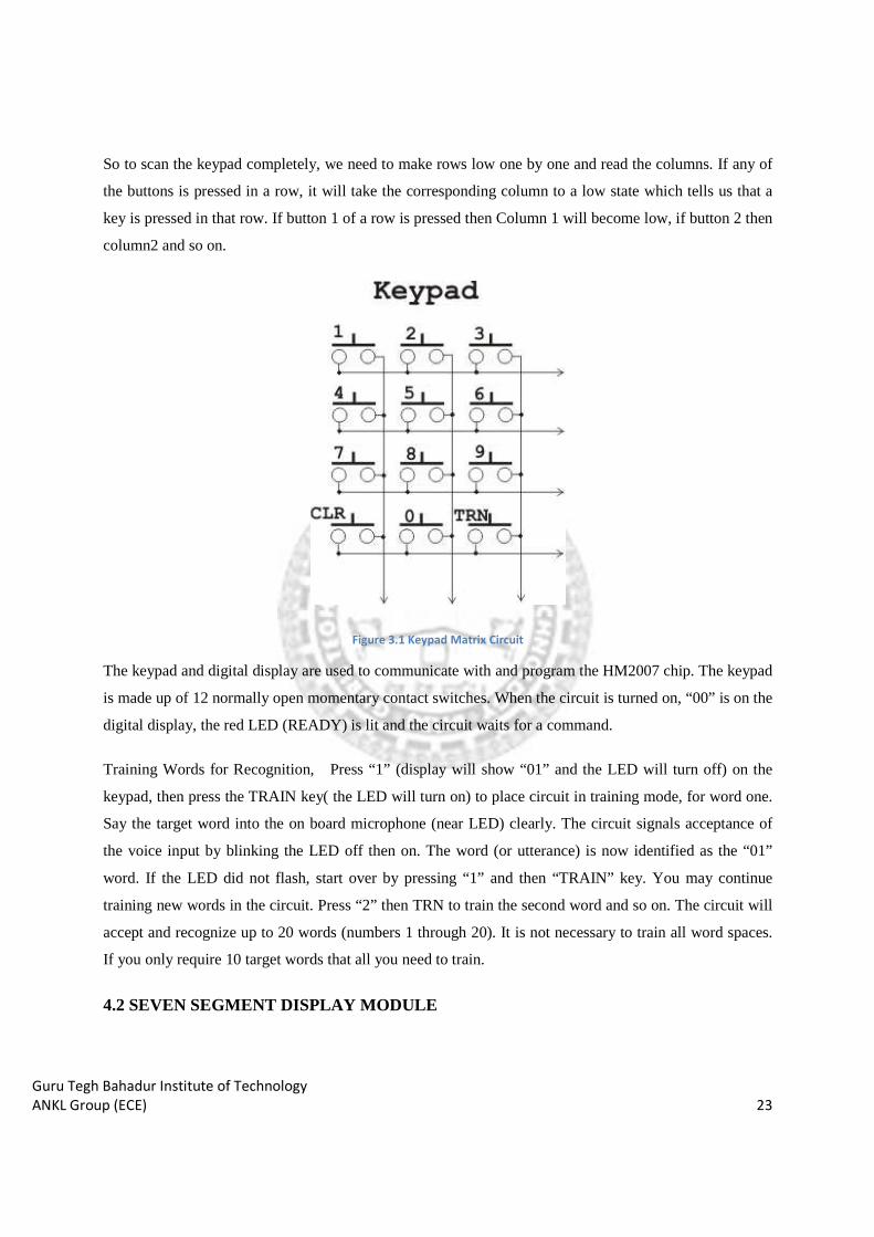
So to scan the keypad completely, we need to make rows low one by one and read the columns. If any of
the buttons is pressed in a row, it will take the corresponding column to a low state which tells us that a
key is pressed in that row. If button 1 of a row is pressed then Column 1 will become low, if button 2 then
column2 and so on.
Figure 3.1 Keypad Matrix Circuit
The keypad and digital display are used to communicate with and program the HM2007 chip. The keypad
is made up of 12 normally open momentary contact switches. When the circuit is turned on, “00” is on the
digital display, the red LED (READY) is lit and the circuit waits for a command.
Training Words for Recognition, Press “1” (display will show “01” and the LED will turn off) on the
keypad, then press the TRAIN key( the LED will turn on) to place circuit in training mode, for word one.
Say the target word into the on board microphone (near LED) clearly. The circuit signals acceptance of
the voice input by blinking the LED off then on. The word (or utterance) is now identified as the “01”
word. If the LED did not flash, start over by pressing “1” and then “TRAIN” key. You may continue
training new words in the circuit. Press “2” then TRN to train the second word and so on. The circuit will
accept and recognize up to 20 words (numbers 1 through 20). It is not necessary to train all word spaces.
If you only require 10 target words that all you need to train.
4.2 SEVEN SEGMENT DISPLAY MODULE
Guru Tegh Bahadur Institute of Technology
ANKL Group (ECE) 24
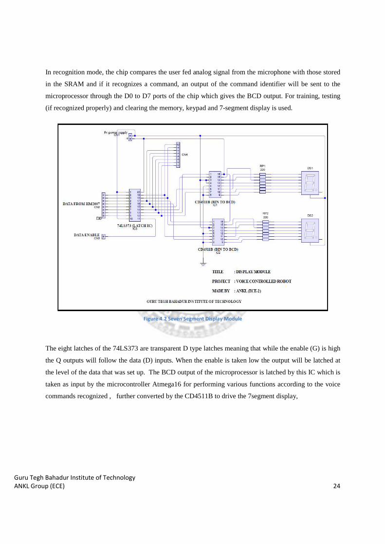
In recognition mode, the chip compares the user fed analog signal from the microphone with those stored
in the SRAM and if it recognizes a command, an output of the command identifier will be sent to the
microprocessor through the D0 to D7 ports of the chip which gives the BCD output. For training, testing
(if recognized properly) and clearing the memory, keypad and 7-segment display is used.
Figure 4.2 Seven Segment Display Module
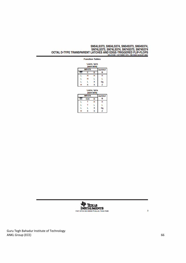
The eight latches of the 74LS373 are transparent D type latches meaning that while the enable (G) is high
the Q outputs will follow the data (D) inputs. When the enable is taken low the output will be latched at
the level of the data that was set up. The BCD output of the microprocessor is latched by this IC which is
taken as input by the microcontroller Atmega16 for performing various functions according to the voice
commands recognized , further converted by the CD4511B to drive the 7segment display,
Guru Tegh Bahadur Institute of Technology
ANKL Group (ECE) 25
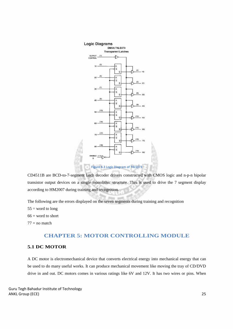
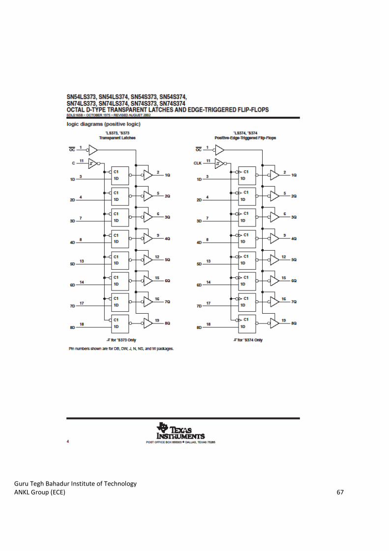
Figure 4.3 Logic Diagram of 74LS373
CD4511B are BCD-to-7-segment latch decoder drivers constructed with CMOS logic and n-p-n bipolar
transistor output devices on a single monolithic structure. This is used to drive the 7 segment display
according to HM2007 during training and recognition.
The following are the errors displayed on the seven segments during training and recognition
55 = word to long
66 = word to short
77 = no match
CHAPTER 5: MOTOR CONTROLLING MODULE
5.1 DC MOTOR
A DC motor is electromechanical device that converts electrical energy into mechanical energy that can
be used to do many useful works. It can produce mechanical movement like moving the tray of CD/DVD
drive in and out. DC motors comes in various ratings like 6V and 12V. It has two wires or pins. When
Guru Tegh Bahadur Institute of Technology
ANKL Group (ECE) 26
connected with power supply the shaft rotates. You can reverse the direction of rotation by reversing the
polarity of input.
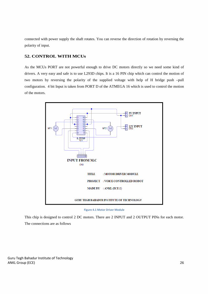
52. CONTROL WITH MCUs
As the MCUs PORT are not powerful enough to drive DC motors directly so we need some kind of
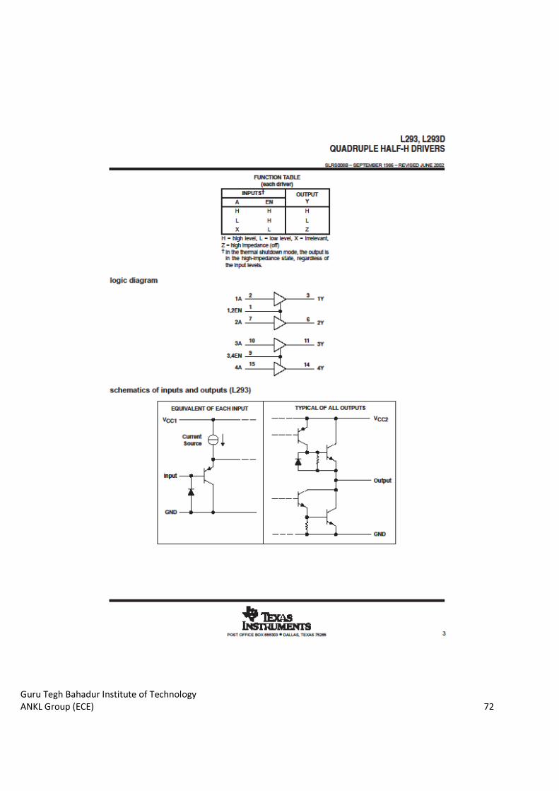
drivers. A very easy and safe is to use L293D chips. It is a 16 PIN chip which can control the motion of
two motors by reversing the polarity of the supplied voltage with help of H bridge push –pull
configuration. 4 bit Input is taken from PORT D of the ATMEGA 16 which is used to control the motion
of the motors.
Figure 4.1 Motor Driver Module
This chip is designed to control 2 DC motors. There are 2 INPUT and 2 OUTPUT PINs for each motor.
The connections are as follows
Guru Tegh Bahadur Institute of Technology
ANKL Group (ECE) 27
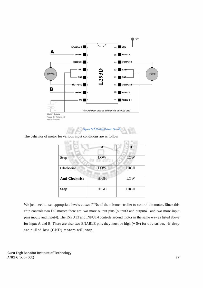
Figure 5.2 Motor Driver Circuit
The behavior of motor for various input conditions are as follow
We just need to set appropriate levels at two PINs of the microcontroller to control the motor. Since this
chip controls two DC motors there are two more output pins (output3 and output4 and two more input
pins input3 and input4). The INPUT3 and INPUT4 controls second motor in the same way as listed above
for input A and B. There are also two ENABLE pins they must be high (+ 5v) for operation, i f they
are pul led low (GND) motors wil l stop.
A B
Stop LOW LOW
Clockwise LOW HIGH
Anti-Clockwise HIGH LOW
Stop HIGH HIGH
Guru Tegh Bahadur Institute of Technology
ANKL Group (ECE) 28
CHAPTER 6: OTHER MODULES
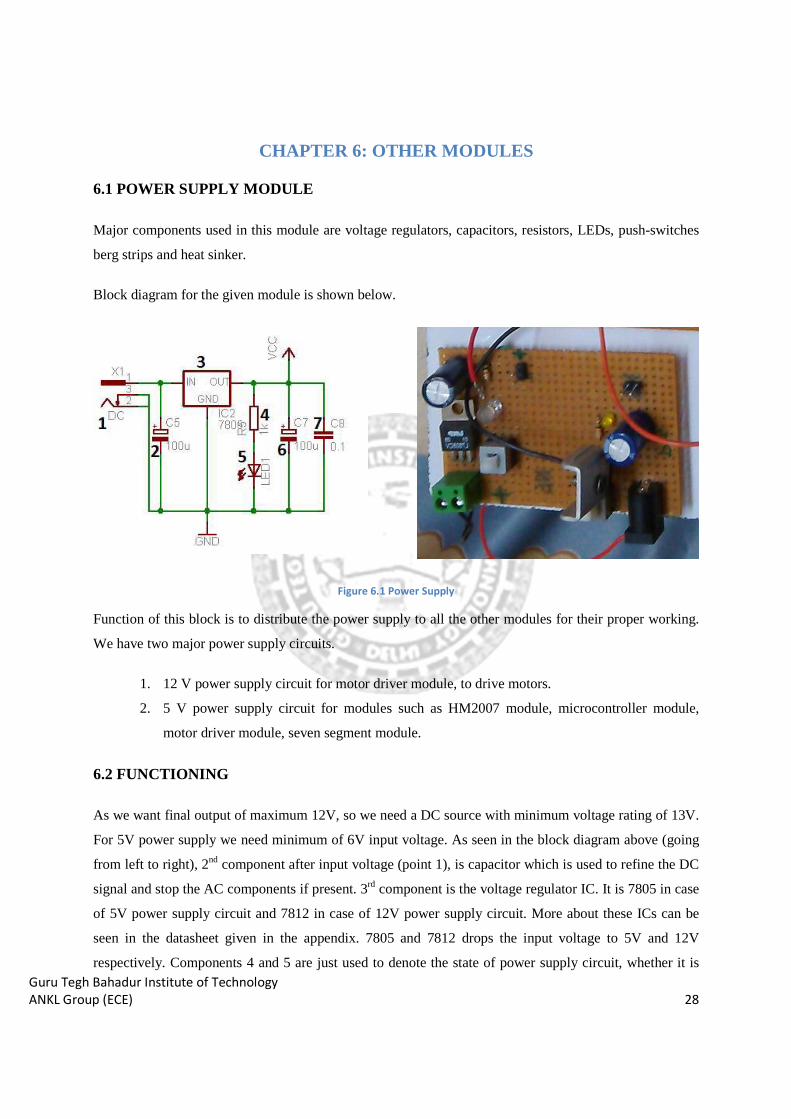
6.1 POWER SUPPLY MODULE
Major components used in this module are voltage regulators, capacitors, resistors, LEDs, push-switches
berg strips and heat sinker.
Block diagram for the given module is shown below.
Figure 6.1 Power Supply
Function of this block is to distribute the power supply to all the other modules for their proper working.
We have two major power supply circuits.
1. 12 V power supply circuit for motor driver module, to drive motors.
2. 5 V power supply circuit for modules such as HM2007 module, microcontroller module,
motor driver module, seven segment module.
6.2 FUNCTIONING
As we want final output of maximum 12V, so we need a DC source with minimum voltage rating of 13V.
For 5V power supply we need minimum of 6V input voltage. As seen in the block diagram above (going
from left to right), 2nd component after input voltage (point 1), is capacitor which is used to refine the DC
signal and stop the AC components if present. 3rd component is the voltage regulator IC. It is 7805 in case
of 5V power supply circuit and 7812 in case of 12V power supply circuit. More about these ICs can be
seen in the datasheet given in the appendix. 7805 and 7812 drops the input voltage to 5V and 12V
respectively. Components 4 and 5 are just used to denote the state of power supply circuit, whether it is
Guru Tegh Bahadur Institute of Technology
ANKL Group (ECE) 29
ON or OFF. Going further, components 6 and 7 are also used to still refine the final output voltage so that
we get the purest form of DC voltage.
IMPORTANT NOTE
Since we have created all modules on different PCBs, each module having its own independent circuitry,
we have to connect the ground pin of all the modules to same position or with each other. This situation is
called as COMMON GROUND condition where all the ground pins are shorted with each other for
proper operation of the circuit. So our main aim is to through the ground/negative pin of the power supply
circuit with all other modules.
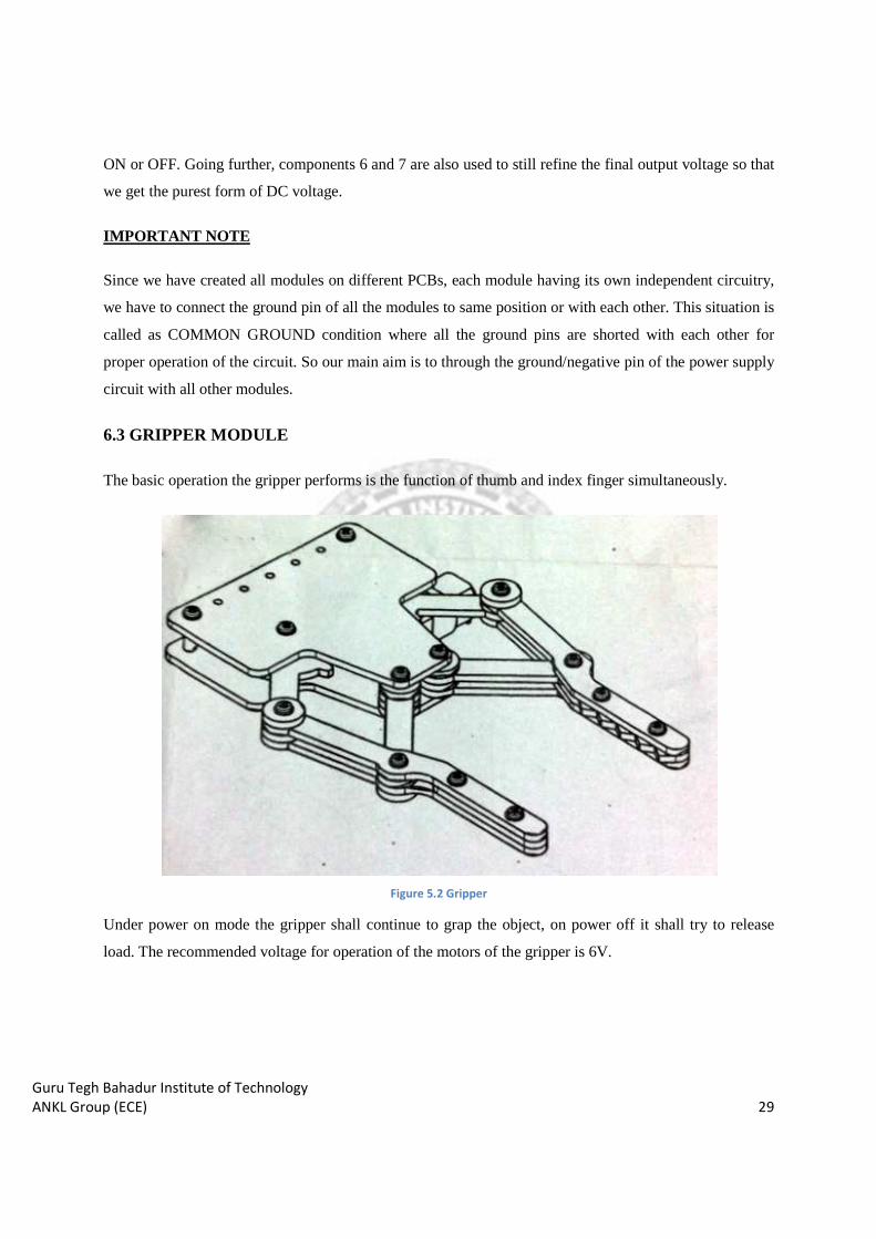
6.3 GRIPPER MODULE
The basic operation the gripper performs is the function of thumb and index finger simultaneously.
Figure 5.2 Gripper
Under power on mode the gripper shall continue to grap the object, on power off it shall try to release
load. The recommended voltage for operation of the motors of the gripper is 6V.
Guru Tegh Bahadur Institute of Technology
ANKL Group (ECE) 30
CHAPTER 7: WORKING FLOW OF PROJECT
To record or train a command, the chip stores the analog signal pattern and amplitude and saves it in the
8kx8 SRAM. In recognition mode, the chip compares the user- inputted analog signal from the
microphone with those stored in the SRAM and if it recognizes a command, an output of the command
identifier will be sent to the microprocessor through the D0 to D7 ports of the chip. For training, testing
(if recognized properly) and clearing the memory, keypad and 7-segment display is used.
STEP1: CONNECTING DISPLAY AND HM2007 MODULE
Firstly connect both Display and HM2007 module with relay-mate. It means connect SRAM input with
the pins at HM2007 as output for SRAM.
STEP2: CONNECTING KEYPAD WITH HM2007
Connect seven input pins of HM2007 with Keypad output pins starting with three columns followed by
four rows.
STEP3: PROVIDING 5V POWER SUPPLY
Now from Power Supply module we provide 5volts to both HM2007 and Display modules, and also
providing common ground to both of these modules. Initially LED on HM2007 module will glow and
Seven Segment of Display module will show 00, it means they are getting 5volt for their functionality.
STEP4: TRAINING HM2007
To train the circuit begins by pressing the word number you want to train on the keypad. Use any
numbers between 1 and 40. For example press the number "1" to train word number 1. When you press
the number(s) on the keypad the red led will turn off. The number is displayed on the digital display. Next
press the "#" key for train. When the "#" key is pressed it signals the chip to listen for a training word and
the red led turns back on. Now speak the word you want the circuit to recognize into the microphone
clearly. The LED should blink off momentarily, this is a signal that the word has been accepted. Continue
training new words in the circuit using the procedure outlined above. Press the "2" key then "#" key to
train the second word and so on. The circuit will accept up to forty words.
Guru Tegh Bahadur Institute of Technology
ANKL Group (ECE) 31
STEP5: TESTING TRAINED HM2007
The circuit is continually listening. Repeat a trained word into the microphone. The number of the word
should be displayed on the digital display. For instance if the word "directory" was trained as word
number 25. Saying the word "directory" into the microphone will cause the number 25 to be displayed.
If unrecognized word is given by user through microphone then error will get displayed on seven
segments. There are three different types of error which are given below:
55 = word too long
66 = word too short
77 = word no match
STEP6: PROGRAMMING ATMEGA 16
Now it’s time to make code for controlling motors of robot. And burn it on microcontroller using suitable
burner.
STEP7: CONNECTING MICROCONTROLLER & MOTOR DRIVER MODULE
Now connect Display module with microcontroller means output pins of latch is connected with any port
(A, B, C, D) which is going to act as input port of microcontroller for coding.
Attach Motor Driver module with motors of robot which is going to be controlled by microcontroller and
give 5 and 12 volt supply to that module. Also provide 5volt supply to microcontroller for its working.
STEP8: FINAL TESTING
Now give commands to HM2007 by through microphone and see the motor movements and display is it
showing the numeric value corresponding to commands. There will be problem in working if we didn’t
make common ground for all the modules.
Guru Tegh Bahadur Institute of Technology
ANKL Group (ECE) 32
CHAPTER 8: SOFTWARE DEVELOPMENT
8.1 USING AVR STUDIO 4
Start> All Programs > Atmel AVR Tools> AVR Studio 4
Now follow the steps below to start using the AVR Studio
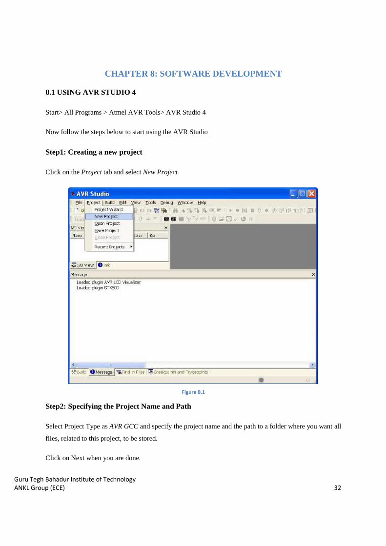
Step1: Creating a new project
Click on the Project tab and select New Project
Figure 8.1
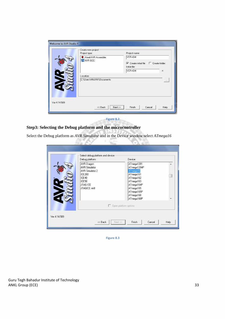
Step2: Specifying the Project Name and Path
Select Project Type as AVR GCC and specify the project name and the path to a folder where you want all
files, related to this project, to be stored.
Click on Next when you are done.
Guru Tegh Bahadur Institute of Technology
ANKL Group (ECE) 33
Figure 8.2
Step3: Selecting the Debug platform and the microcontroller
Select the Debug platform as AVR Simulator and in the Device window select ATmega16
Figure 8.3
Guru Tegh Bahadur Institute of Technology
ANKL Group (ECE) 34
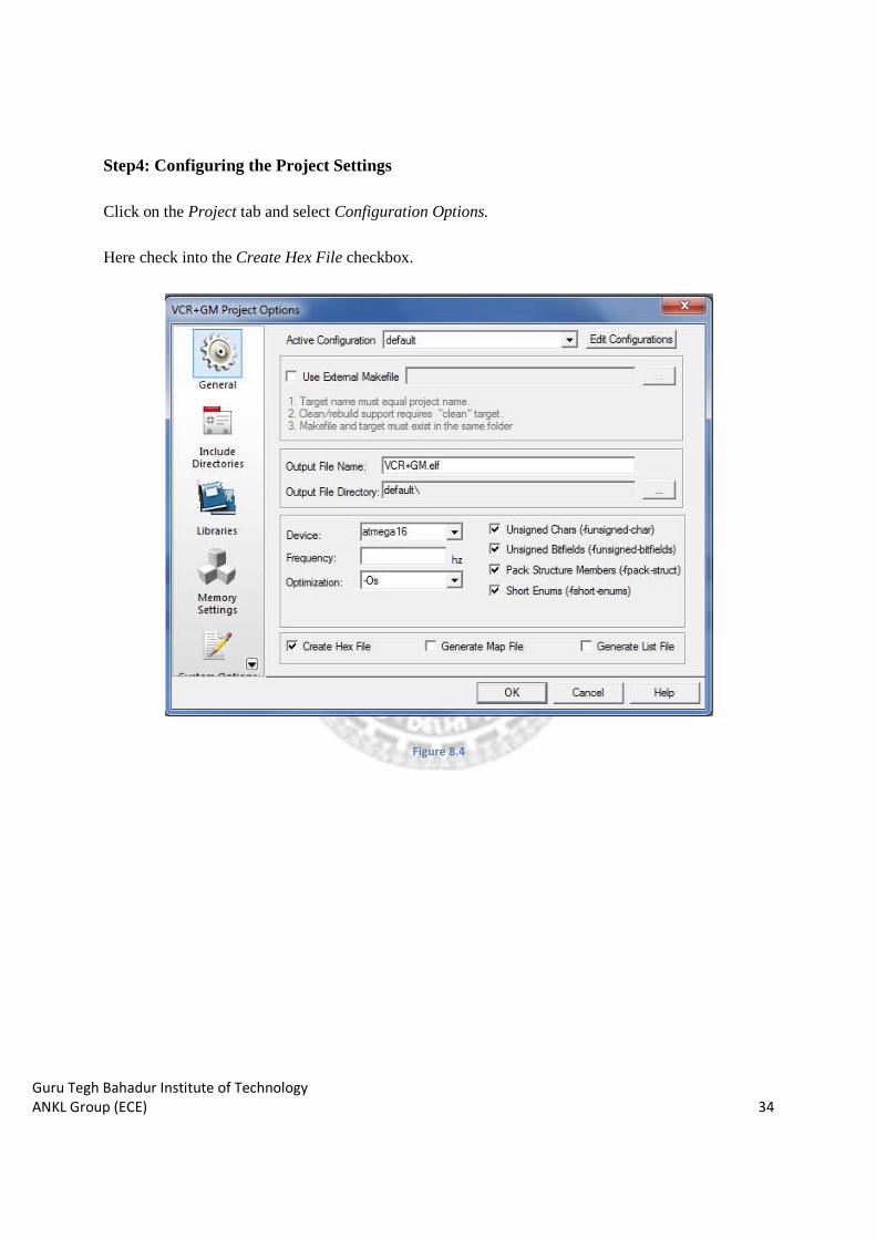
Step4: Configuring the Project Settings
Click on the Project tab and select Configuration Options.
Here check into the Create Hex File checkbox.
Figure 8.4

Guru Tegh Bahadur Institute of Technology
ANKL Group (ECE) 35
Step5: Getting started with coding
5.1 Adding the header files
#include <avr/io.h>
#include <util/delay.h>
5.2 Defining the I/O port directions and using the optional Pull-up resisters
To do this we need to write proper values into the following two registers. So lets take a small diversion
to understand what they do.
1. Data direction register (DDRx)
The purpose of the data direction register is to determine which bits of the port are used for input and
which bits are used for output. If DDRx is written logic one, port pin is configured as an output pin. If
DDRx is written logic zero, port pin is configured as an input pin.
DDRA = 0xF0; //sets the 4 MSB bits of portA as output port and
//4 LSB bits as input port
2. Port drive register (PORTx)
If the port is configured as output port PORTx register drives the corresponding value on output pins of
the port.
DDRA = 0xFF; //set all 8 bits of PORTA as output
PORTA = 0xF0; //output logic high on 4 MSB pins and logic low on 4 LSB pins
For pins configured as input microcontroller supply the pull up register by writing a logic 1 to the
corresponding bit of the port driver register
DDRA = 0x00; //set all 8 bits of PORTA as input
PORTA = 0xFF; //pull up register is assigned to all the pins;

Guru Tegh Bahadur Institute of Technology
ANKL Group (ECE) 36
Having understood this, let’s go ahead and write a subroutine which will initialize the I/O port directions.
void port_init(void)
{
DDRA = 0xFF;
PORTA = 0x00;
DDRB = 0xF7;
PORTB = 0x7F;
DDRC = 0xFF;
PORTC = 0x00;
DDRD = 0x00;
PORTD = 0xFF;
DDRE = 0x7C;
PORTE = 0xFF;
DDRF = 0x00;
PORTF = 0x00;
DDRG = 0x00;
PORTG = 0x1F;
}
Step6: Compiling and Building the code
Click on the Build tab and select the Build or Compile option or else select the following shortcuts on the
toolbar
Compile (Alt+ F7)
Build (F7)
Step7: Programming the Microcontroller
The hex file is burned in the microcontroller using Khazama.
Guru Tegh Bahadur Institute of Technology
ANKL Group (ECE)
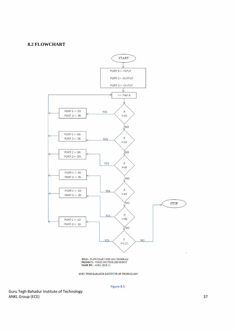
8.2 FLOWCHART
Figure 8.5
37

Guru Tegh Bahadur Institute of Technology
ANKL Group (ECE) 38
CHAPTER 9: DIFFICULTIES FACED DURING THE PREPARATION
There were different phases in the project preparation during all these days. Each phase had some
difficulties associated with it depending on the ongoing circumstances. This chapter will describe about
all the difficulties faced in each phase of the project development.
PHASE 1: IDEA GENERATION PHASE
This was the very first phase of our project development. We were constrained while choosing our project.
We had to check the availability of each and every thing we are going to use, because there are many
components that are not available easily and in local electronics market. Still we managed to get
interesting and innovative idea of our project. We bought some components from Mumbai. Major risk
attached was with the durability of the expensive components. At last everything went well and finally we
are ready with our final product.
PHASE 2: COMPONENT PURCHASING PHASE
This was the second phase, which includes tasks like preparing the list for the required components and
then purchasing them. One of most important problem is that to find HM2007 IC which is heart of our
project and we were unable to find it, but after a long searching we are able to find it and we cart it from
Mumbai. But even getting heart of our project we are not getting where to fit it means we have to find
base for it. We searched it in Lajpat Rai market and with variation of rate we find at most possible
minimum prize. All others components are not very difficult to find it.
PHASE 3: HARDWARE DEVELOPMENT PHASE
First problem we get in soldering HM2007 as square package is new to us and we have to find it how its
numbering is done and we have to be very precise in soldering so that no two legs of base get short.
Second thing we faced is how to connect Seven Segment to PCB as it is very sensible to temperature and
get damaged and we damaged one of the two seven segment. So we get an idea to connect it through
female connector means making base for it. Thirdly we face a problem of removing our microcontroller
again and again for burning so we search for solution and come up with a ZIF socket concept to use in our
project to save our microcontroller.

Guru Tegh Bahadur Institute of Technology
ANKL Group (ECE) 39
PHASE 4: HARDWARE TESTING PHASE
After getting all module completed we start testing our modules testing separately we come up with some
faults which are minor problems after rectifying them we test them separately with test programs when
we get all module functioning correctly as they have to we start connecting them with each other. After
getting all of them connected we run our one of test program to test our whole hardware but we didn’t get
answer due to common grounding problem which we rectify and get hardware functional.
PHASE 5: SOFTWARE DEVELOPMENT PHASE
This was completely a different phase from all the previous ones. The AVR platform was new to
us and we had to learn everything from the scratch to understand the basic concepts and then
start programming. In programming main problem we got was with the clock cycle of the
microcontroller. Some other problems that we got were related to delay function and header file.
PHASE 6: SOFTWARE TESTING AND DEBUGGING PHASE
In this phase we had to burn the code onto the microcontroller. First problem here was to find a
suitable burner kit to burn the software onto the ATMega16 IC. Testing include checking the
connections according to programming we had done. Main problem we came across was while
we have to interchange the connections according to our programming.

Guru Tegh Bahadur Institute of Technology
ANKL Group (ECE) 40
CHAPTER 10: APPLICATIONS
We believe such a system would find wide variety of applications. Menu driven systems such as
e-mail readers, household appliances like washing machines, microwave ovens, and pagers and
mobiles etc. will become voice controlled in future
• The robot is useful in places where humans find difficult to reach but human voice
reaches. E.g. in a small pipeline, in a fire-situations, in highly toxic areas.
• The robot can be used as a toy.
• It can be used to bring and place small objects.
• It is the one of the important stage of Humanoid robots.
• Command and control of appliances and equipment
• Telephone assistance systems
• Data entry
• Speech and voice recognition security systems

Guru Tegh Bahadur Institute of Technology
ANKL Group (ECE) 41
CONCLUSION
The voice recognition software has accuracy around 70% to 80% in correctly identifying a voice
command. But it is highly sensitive to the surrounding noises. There is a possibility of misinterpreting
some noises as one of the voice commands given to the robot. Also the accuracy of word recognition
reduces in face of the noise. The sound coming from motors has a significant effect on accuracy.
There are some drawbacks in the mobile platform. The rechargeable 6V batteries carried onboard makes
it too heavy. Hence we had to use powerful motors to drive the robot making the power consumption
higher. So we had to recharge the batteries quite often. The mobile platform had some problems in
turning due to the heaviness of itself. The Gripper also face problem in gripping due to low power so we
need high power to drive it. The back freewheels used to get stuck when turning especially in reverse
motion. Hence we suggest that steering mechanism will be a better option.

Guru Tegh Bahadur Institute of Technology
ANKL Group (ECE) 42
APPENDICES

Guru Tegh Bahadur Institute of Technology
ANKL Group (ECE) 43
APPENDIX I BLOCK DIAGRAM OF THE PROJECT
Guru Tegh Bahadur Institute of Technology
ANKL Group (ECE) 44
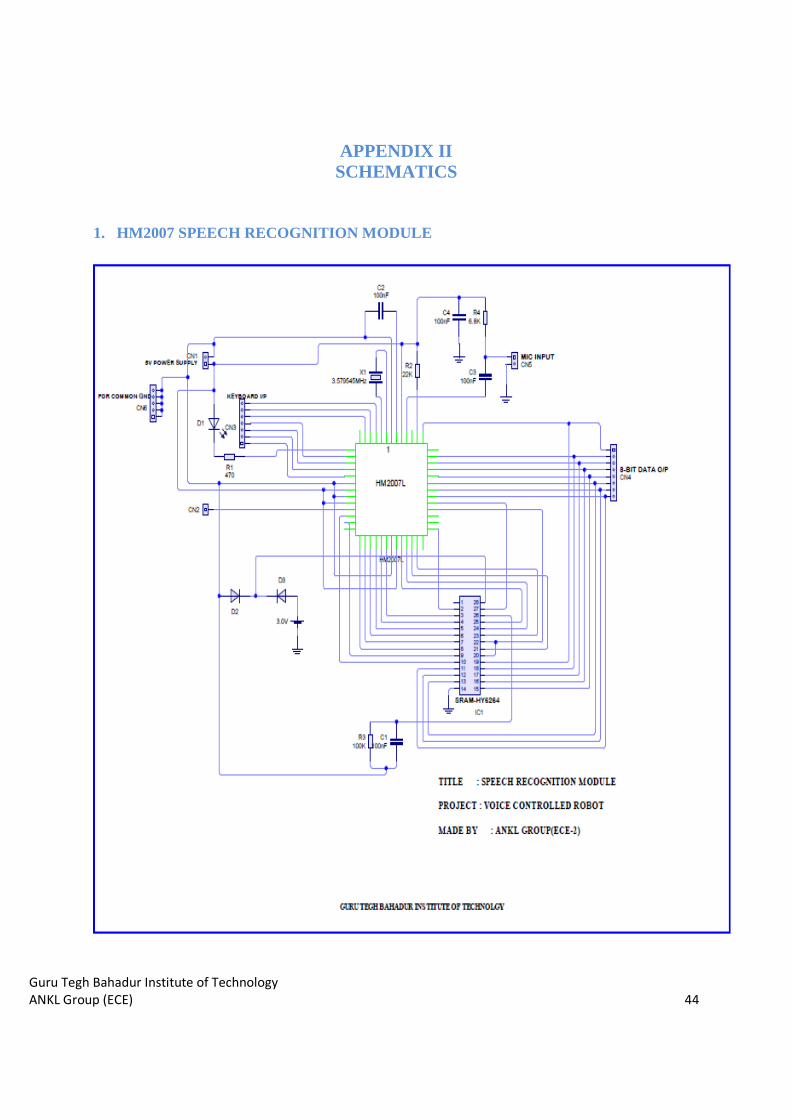
APPENDIX II SCHEMATICS
1. HM2007 SPEECH RECOGNITION MODULE
Guru Tegh Bahadur Institute of Technology
ANKL Group (ECE) 45
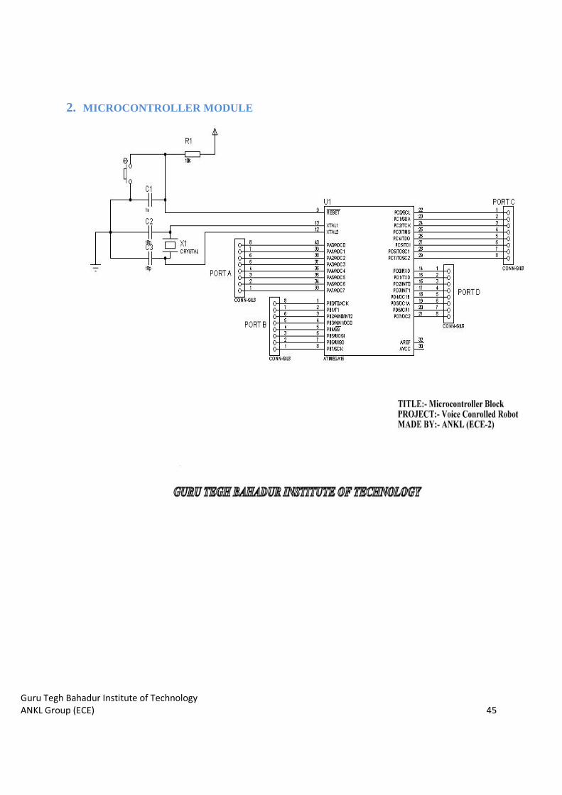
2. MICROCONTROLLER MODULE
Guru Tegh Bahadur Institute of Technology
ANKL Group (ECE) 46
3. DISPLAY MODULES

Guru Tegh Bahadur Institute of Technology
ANKL Group (ECE) 47
4. KEYPAD MODULE
5. MOTOR DRIVER MODULE
Guru Tegh Bahadur Institute of Technology
ANKL Group (ECE) 48
6. POWER SUPPLY

Guru Tegh Bahadur Institute of Technology
ANKL Group (ECE) 49
APPENDIX III
Guru Tegh Bahadur Institute of Technology
ANKL Group (ECE)
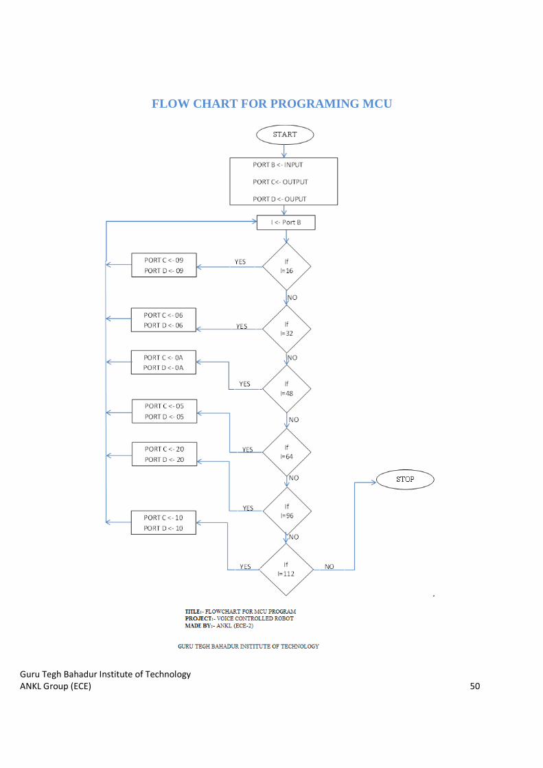
FLOW CHART FOR PROGRAMING MCU
FLOW CHART FOR PROGRAMING MCU
50
FLOW CHART FOR PROGRAMING MCU
Guru Tegh Bahadur Institute of Technology
ANKL Group (ECE) 51
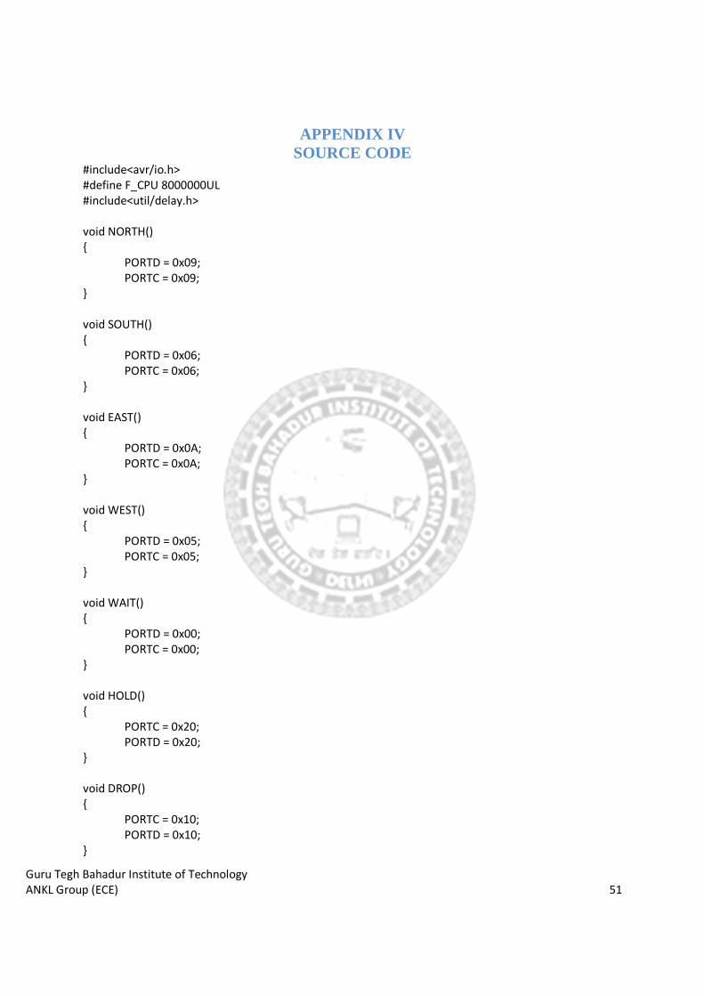
APPENDIX IV SOURCE CODE
#include<avr/io.h>
#define F_CPU 8000000UL
#include<util/delay.h>
void NORTH()
{
PORTD = 0x09;
PORTC = 0x09;
}
void SOUTH()
{
PORTD = 0x06;
PORTC = 0x06;
}
void EAST()
{
PORTD = 0x0A;
PORTC = 0x0A;
}
void WEST()
{
PORTD = 0x05;
PORTC = 0x05;
}
void WAIT()
{
PORTD = 0x00;
PORTC = 0x00;
}
void HOLD()
{
PORTC = 0x20;
PORTD = 0x20;
}
void DROP()
{
PORTC = 0x10;
PORTD = 0x10;
}

Guru Tegh Bahadur Institute of Technology
ANKL Group (ECE) 52
void delay_ms(int d)
{
_delay_ms(d);
}
int main(void)
{
unsigned char i;
DDRB = 0x00;
DDRC = 0xFF;
DDRD = 0xFF;
while(1)
{
i = PINB;
if(i==16)
{
NORTH();
WAIT();
}
else if(i==32)
{
SOUTH();
WAIT();
}
else if(i==48)
{
EAST();
WAIT();
}
else if(i==64)
{
WEST();
WAIT();
}
else if(i==80)
{
WAIT();
}
Guru Tegh Bahadur Institute of Technology
ANKL Group (ECE) 53
else if(i==96)
{
HOLD();
WAIT();
}
else if(i==112)
{
DROP();
WAIT();
}
else
{
WAIT();
}
}
return 0;
}

Guru Tegh Bahadur Institute of Technology
ANKL Group (ECE) 54
APPENDIX V
DATASHEETS
Guru Tegh Bahadur Institute of Technology
ANKL Group (ECE) 55
1. HM2007
Guru Tegh Bahadur Institute of Technology
ANKL Group (ECE) 56
Guru Tegh Bahadur Institute of Technology
ANKL Group (ECE) 57

Guru Tegh Bahadur Institute of Technology
ANKL Group (ECE) 58
Guru Tegh Bahadur Institute of Technology
ANKL Group (ECE) 59
2. ATMEGA 16 L

Guru Tegh Bahadur Institute of Technology
ANKL Group (ECE) 60

Guru Tegh Bahadur Institute of Technology
ANKL Group (ECE) 61

Guru Tegh Bahadur Institute of Technology
ANKL Group (ECE) 62

Guru Tegh Bahadur Institute of Technology
ANKL Group (ECE) 63
3. HY6264A

Guru Tegh Bahadur Institute of Technology
ANKL Group (ECE) 64
4. 74LS373

Guru Tegh Bahadur Institute of Technology
ANKL Group (ECE) 65
Guru Tegh Bahadur Institute of Technology
ANKL Group (ECE) 66
Guru Tegh Bahadur Institute of Technology
ANKL Group (ECE) 67

Guru Tegh Bahadur Institute of Technology
ANKL Group (ECE) 68
5. CD4511B

Guru Tegh Bahadur Institute of Technology
ANKL Group (ECE) 69
6. L293D

Guru Tegh Bahadur Institute of Technology
ANKL Group (ECE) 70

Guru Tegh Bahadur Institute of Technology
ANKL Group (ECE) 71
Guru Tegh Bahadur Institute of Technology
ANKL Group (ECE) 72

Guru Tegh Bahadur Institute of Technology
ANKL Group (ECE) 73
REFERENCES
[1] Raj Kamal, ‘Embedded System: Architecture, Programming and Design’, Tata McGraw-Hill Education, 01-Jul-2003
[2] THOMAS, T. Voice processing: why speech recognizers make mistakes. Systems International (UK). 15, 10 (1987)
[3] VAN PEURSEM, R.S. Speech recognition for quality
systems. Quality. 26, 11 (1987), 48-49
[4] FIORE, A. Pros and cons of voice systems. Computerworld. 22, 20 (1988), 79
[5] Geoff Bristow, Electronic speech recognition: techniques,
technology, and applications, McGraw-Hill, Inc., New York, NY, 1986
[6] George Philip , Elizabeth S. Young, Man—machine
interaction by voice: developments in speech technology. Part 2: general applications and potential applications in libraries and information services, Journal of Information Science, v.13 n.1, p.15-23, Feb. 1987
[7] Grant, P.M., ‘Speech recognition techniques’, IEEE
Electronics & Communication Engineering Journal, Feb 1991
[8] Speech Recognition: The Complete Practical Reference
Guide; T. Schalk, P. J. Foster: Telecom Library Inc, New York; ISBN O-9366648-39-2
[9] Richard L. Klevans, Robert D. Rodman, 'Voice
recognition', Artech House, 1997
[10] HM2007 (2006) 'HM2007 Voice Recognition IC', ITP Sensor Workshop, Vol. 2008.
[11] Steven Frank Barrett, Daniel J. Pack, 'Atmel AVR
Microcontroller Primer: Programming and Interfacing', Morgan & Claypool Publishers, 2008
[12] Muhammad Ali Mazidi, Janice Mazidi, Sarmad Naimi,
Sepehr Naimi, 'Avr Microcontroller and Embedded Systems: Using Assembly and C', Prentice Hall, 2010
[13] Richard H. Barnett, Larry D. O'Cull, Sarah A. Cox,
Sarah Alison Cox, 'Embedded C Programming And the Atmel AVR', Cengage Learning, 2007
[14] Muhammad Rashid, ‘Power Electronics Handbook: Devices, Circuits, and Applications’, Elsevier, 09-Dec-2010 - Technology & Engineering
[15] Robert Daniel Twomey, ‘Seven segment display’,
University of California, San Diego, 2007
[16] ROBOT" Merriam-Webster Online Dictionary. 2010[Online]. Available: http://www.merriam-webster.com/dictionary/robot
[17] “Robot” American Heritage Dictionary. 2010 [Online].
Available:http://education.yahoo.com/reference/dictionary/entry/robot
[18] Bright Hub 2010. [Online]. Available:
http://www.brighthub.com/engineering/mechanical/articles/7 1937.aspx
[19] Joris de Ruiter, Natural Language Interaction - the understanding computer, 2010 [Online], Available:www.few.vu.nl/~jdruiter/published_work/Natural_language_interaction.pdf
[20] Modern Digital Electronics –RP Jain, 3rd edition; Tata
Mcgraw Hill; Chapter 6&10. For A/D converter and 7 segment display connections.
[21] Sunpreet Kaur Nanda, Akshay P.Dhande,
‘Microcontroller Implementation of a Voice Command Recognition System for Human Machine Interface in Embedded System’, International Journal of Electronics, Communication & Soft Computing Science and Engineering (IJECSCSE), Volume 1, Issue 1
[22] H. Dudley, The Vocoder, Bell Labs Record, Vol. 17, pp.
122-126, 1939.
[23] H. Dudley, R. R. Riesz, and S. A. Watkins, A Synthetic Speaker, J.Franklin Institute, Vol.227, pp. 739-764, 1939.
[24] J. G. Wilpon and D. B. Roe, AT&T Telephone Network
Applications of Speech Recognition, Proc. COST232 Workshop, Rome, Italy, Nov. 1992.
[25] C. G. Kratzenstein, Sur la raissance de la formation des
voyelles, J. Phys., Vol 21, pp. 358-380, 1782.

Guru Tegh Bahadur Institute of Technology
ANKL Group (ECE) 74
[26] H. Dudley and T. H. Tarnoczy, The Speaking Machine of Wolfgang von Kempelen, J. Acoust. Soc. Am., Vol. 22, pp. 151-166, 1950.
[27] J. L. Flanagan, Speech Analysis, Synthesis and
Perception, Second Edition, Springer-Verlag,1972.
[28] H. Fletcher, The Nature of Speech and its Interpretations, Bell Syst. Tech. J., Vol 1, pp. 129-144, July 1922.
[29] K. H. Davis, R. Biddulph, and S. Balashek, Automatic
Recognition of Spoken Digits, J.Acoust. Soc. Am., Vol 24, No. 6, pp. 627-642, 952.
[30] H. F. Olson and H. Belar, Phonetic Typewriter, J. Acoust.
Soc. Am., Vol. 28, No. 6, pp.1072-1081, 1956.
[31] J. W. Forgie and C. D. Forgie, Results Obtained from a Vowel Recognition Computer Program, J. Acoust. Soc. Am., Vol. 31, No. 11, pp. 1480-1489, 1959.
[32] J. Sakai and S. Doshita, The Phonetic Typewriter,
Information Processing 1962, Proc. IFIP Congress, Munich, 1962.
[33] K. Nagata, Y. Kato, and S. Chiba, Spoken Digit
Recognizer for Japanese Language, NEC Res. Develop., No. 6, 1963.
[34] D. B. Fry and P. Denes, The Design and Operation of the
Mechanical Speech Recognizer at University College London, J. British Inst. Radio Engr., Vol. 19, No. 4, pp. 211-229, 1959.
[35] T. B. Martin, A. L. Nelson, and H. J. Zadell, Speech
Recognition by Feature Abstraction Techniques, Tech. Report AL-TDR-64-176, Air Force Avionics Lab, 1964.
[36] T. K. Vintsyuk, Speech Discrimination by Dynamic
Programming, Kibernetika, Vol. 4, No. 2, pp. 81-88, Jan.-Feb. 1968.
[37] H. Sakoe and S. Chiba, Dynamic Programming
Algorithm Quantization for Spoken Word Recognition, IEEE Trans. Acoustics, Speech and Signal Proc., Vol. ASSP-26, No. 1, pp. 43- 49, Feb. 1978.
[38] B. S. Atal and S. L. Hanauer, Speech Analysis and
Synthesis by Linear Prediction of the Speech Wave, J. Acoust. Soc. Am. Vol. 50, No. 2, pp. 637-655, Aug. 1971.
[39] F. Itakura and S. Saito, A Statistical Method for
Estimation of Speech Spectral Density and Formant
Frequencies, Electronics and Communications in Japan, Vol. 53A, pp. 36-43, 1970.
[40] F. Itakura, Minimum Prediction Residual Principle
Applied to Speech Recognition, IEEE Trans. Acoustics, Speech and Signal Proc., Vol. ASSP-23, pp. 57-72, Feb. 1975.
[41] L. R. Rabiner, S. E. Levinson, A. E. Rosenberg and J. G.
Wilpon, Speaker Independent Recognition of Isolated Words Using Clustering Techniques, IEEE Trans. Acoustics, Speech and Signal Proc., Vol. Assp-27, pp. 336-349, Aug. 1979.
[42] B. Lowerre, The HARPY Speech Understanding System,
Trends in Speech Recognition, W. Lea, Editor, Speech Science Publications, 1986, reprinted in Readings in Speech Recognition, A. Waibel and K. F. Lee, Editors, pp. 576-586, Morgan Kaufmann Publishers, 1990.
[43] M. Mohri, Finite-State Transducers in Language and
Speech Processing, Computational Linguistics, Vol. 23, No. 2, pp. 269- 312, 1997.
[44] Dennis H. Klatt, Review of the DARPA Speech
Understanding Project (1), J. Acoust. Soc. Am., 62, 1345-1366, 1977.
[45] F. Jelinek, L. R. Bahl, and R. L. Mercer, Design of a
Linguistic Statistical Decoder for the Recognition of Continuous Speech, IEEE Trans. On Information Theory, Vol. IT-21, pp. 250- 256, 1975.
[46] C. Shannon, A mathematical theory of communication,
Bell System Technical Journal, vol.27, pp. 379-423 and 623-656, July and October, 1948.
[47] S. K. Das and M. A. Picheny, Issues in practical large
vocabulary isolated word recognition: The IBM Tangora system, in Automatic Speech and Speaker Recognition Advanced Topics, C.H. Lee, F. K. Soong, and K. K. Paliwal, editors, p. 457-479, Kluwer, Boston, 1996.
[48] B. H. Juang, S. E. Levinson and M. M. Sondhi,
Maximum Likelihood Estimation for Multivariate Mixture Observations of Markov Chains, IEEE Trans. Information Theory, Vol. It-32, No. 2, pp. 307-309, March 1986.
[49] Dr. S.K Saxena, Rachna Jain, Delhi Technical University,
‘Voice Automated Mobile Robot’, International Journal of Computer Applications, Volume 16– No.2, February 2011