visualization digital display unit dpa description
TRANSCRIPT
Specials
Order code . . . . . . . . . page |04|
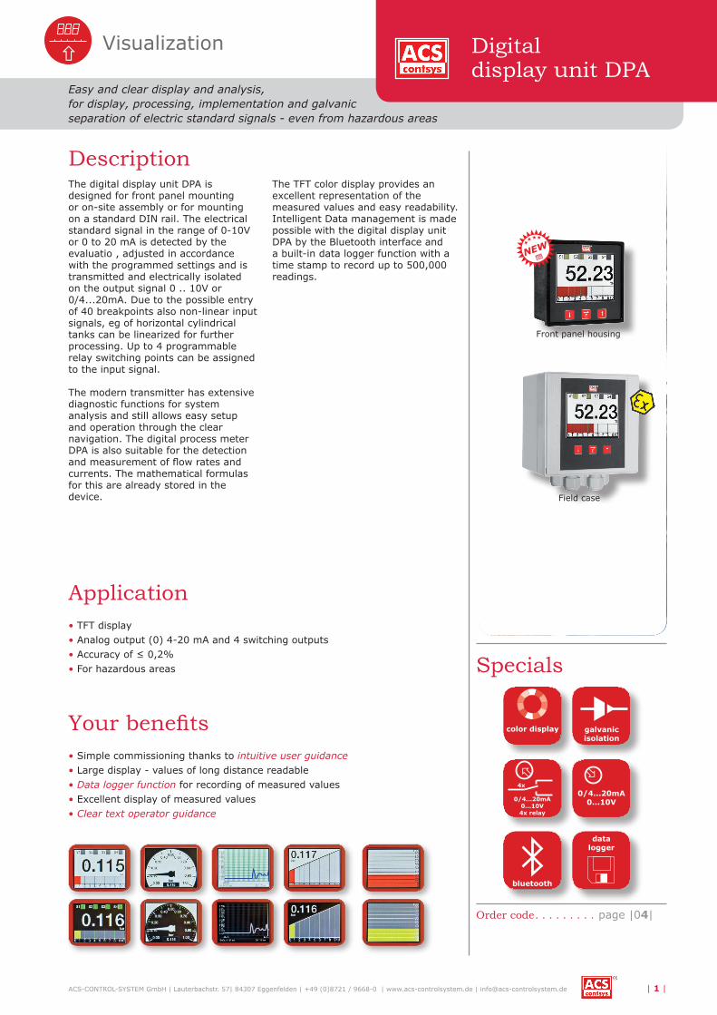
Description
Visualization
ACS-CONTROL-SYSTEM GmbH | Lauterbachstr. 57| 84307 Eggenfelden | +49 (0)8721 / 9668-0 | www.acs-controlsystem.de | [email protected] | 1 |
Easy and clear display and analysis,for display, processing, implementation and galvanic separation of electric standard signals - even from hazardous areas
The digital display unit DPA is designed for front panel mounting or on-site assembly or for mounting on a standard DIN rail. The electrical standard signal in the range of 0-10V or 0 to 20 mA is detected by the evaluatio , adjusted in accordance with the programmed settings and is transmitted and electrically isolated on the output signal 0 .. 10V or 0/4...20mA. Due to the possible entry of 40 breakpoints also non-linear input signals, eg of horizontal cylindrical tanks can be linearized for further processing. Up to 4 programmable relay switching points can be assigned to the input signal.
The modern transmitter has extensive diagnostic functions for system analysis and still allows easy setup and operation through the clear navigation. The digital process meter DPA is also suitable for the detection and measurement of flow rates and currents. The mathematical formulas for this are already stored in the device.
The TFT color display provides an excellent representation of the measured values and easy readability. Intelligent Data management is made possible with the digital display unit DPA by the Bluetooth interface and a built-in data logger function with a time stamp to record up to 500,000 readings.
0/4...20mA0...10V4x relay
4x0/4...20mA
0...10V
bluetooth
datalogger
color display galvanicisolation
Digitaldisplay unit DPA
• TFT display• Analog output (0) 4-20 mA and 4 switching outputs• Accuracy of ≤ 0,2%• For hazardous areas
• Simple commissioning thanks to intuitive user guidance• Large display - values of long distance readable• Data logger function for recording of measured values• Excellent display of measured values• Clear text operator guidance
Your benefits
Application
Front panel housing
Field case
NEW

Technical data
| 2 | ACS-CONTROL-SYSTEM GmbH | Lauterbachstr. 57| 84307 Eggenfelden | +49 (0)8721 / 9668-0 | www.acs-controlsystem.de | [email protected]
Technical data
Supply voltage: Type A / B / D: 18..36V DC, reverse polarity protectedType S / T / U: 186..253VAC
Power consumption: Type A/B/D: ≤ 5 WType S/T/U: ≤ 20 VA
Isolation voltage:
Type A/B/D:Auxiliary power 1kV AC; Relay outputs 3kV AC;Input analogue/digital – output analogue 500V DCType S/T/U:Auxiliary power 3kV AC; Relay outputs 3kV AC;Input analogue/digital – output analogue 500V DC
Input Signal I – InA1: Signal 0…20mA: 0mA ... 21mA, max. 30mASignal 4…20mA: 3,9mA ... 21mA, max. 30mA
Input Signal U – InA1: Signal 0…10V: 0 ... 10,5V, max. 15V (UIn max ≤ 30V)
Digital input – InD1…4 (IEC 61131-2): Signal low – logic 0: -3 ... 5VSignal high – logic 1: -12 ... 30V (UIn max ≤ 36V)
Transmitter supply: 0…28mA, max. ≤ 35mA, current limited/short circuit proof
Output Signal I – OutA1: Signal 0…20mA: 0mA ... 20,5mA/22mASignal 4…20mA: 3,6/3,8mA ... 20,5mA/22mA
Output Signal U – OutA1 Signal 0…10V: 0 ... 10,5V, max. 11V
Switching output
Function: Potential-free changeover contact
Maximum switching power AC: 253VAC – 6A – 1500VA (ohmic load) / 300VA (cos φ ≥ 0,7)
Maximum switching power DC:30VDC – 6A – 180W110VDC – 0,2A – 22W220VDC – 0,12A – 26,4W
Response time tOn/Off: ≤ 20ms (td = 0s)
Bluetooth interfaceVersion 2.0 Full Speed
Function Host
Jack socket USB 2.0-A
Measurement accuracy
Characteristic deviation: Input U/I – InA1: ≤ ±0,05% FSOutput U/I – OutA1: ≤ ±0,05% FS
Temperature deviation: Input U/I – InA1: ≤ ±0,1% FS / 10KOutput U/I – OutA1: ≤ ±0,1% FS / 10K
Materials
DIN rail housing: PC / PES / CrNi-steel / PA / CR-NBR
Wall-mount housing: PC / PES / CrNi-steel / PA / CR-NBR
Front panel housing: PPE / PES / steel zinc-coated / CrNi-steel / PA / NBR-EPDM
Environmental conditions
Ambient temperature:-20 ° C. .. +50 ° CExpansionBacklight LCD ≤ 85% >> -20°C...+60°C
Protection wall mounting housing /DIN rail housing: IP65 EN/IEC 60529
Protection front panel housing:front IP54 EN/IEC 60529rear IP20 EN/IEC 60529Electronic extras type 2 – increased protection class front panel enclosureFront side IP65 (EN/IEC 60529)
ATEX: ATEX II (1) G [Ex ia Ga] IIC resp. ATEX II (1) D [Ex ia Da] IIIC

Dimension drawings
ACS-CONTROL-SYSTEM GmbH | Lauterbachstr. 57| 84307 Eggenfelden | +49 (0)8721 / 9668-0 | www.acs-controlsystem.de | [email protected] | 3 |
Digitaldisplay unit DPA
DIN rail housingType F
Connection housingWall mounted housingType P - Elektronik Typ S / T / U
Front panel enclosureType M

| 4 | ACS-CONTROL-SYSTEM GmbH | Lauterbachstr. 57| 84307 Eggenfelden | +49 (0)8721 / 9668-0 | www.acs-controlsystem.de | [email protected]
Order Code
Sta
nd 0
4/20
17
DPAOrder code
Electronic – input1 1x 0/4…20mA - 0…10V, transmitter power supply
Approval 0 Standard X ATEX II (1) G / ATEX II (1) D
Enclosure type F Field enclosure M Front panel enclosure P DIN-rail enclosure
Electronic – supply / output A 18…36V DC / 1x 0/4…20mA - 0…10V B 18…36V DC / 1x 0/4…20mA - 0…10V, 2x relay, 2x digital input D 18…36V DC / 1x 0/4…20mA - 0…10V, 4x relay, 4x digital input S 186…253V AC / 1x 0/4…20mA - 0…10V T 186…253V AC / 1x 0/4…20mA - 0…10V, 2x relay, 2x digital input U 186…253V AC / 1x 0/4…20mA - 0…10V, 4x relay, 4x digital input
Electronic - function 0 USB-Interface 1 USB+Bluetooth-Interface 2 USB-Interface / Data logger with time stamp, battery powered 3 USB+Bluetooth-Interface / Data logger with time stamp, battery powered Y others
Electronic - extras 0 Standard 1 USB device jack – Enclosure type F / P 2 Increased protection class IP65 – Enclosure type M
S Standard
S1