visual signals - army electronic publications & forms
TRANSCRIPT
FM 21-60
Visual Signals
HEADQUARTERS, DEPARTMENT OF THE ARMY SEPTEMBER 1987
DISTRIBUTION RESTRICTION: ‘Approved for public release; distribution is unlimited.’
CHAPTER 1 INTRODUCTION
1-1. General
Visual signals are any means of communication that require sight andcan be used to transmit prearranged messages rapidly over short dis-tances. This includes the devices and means used for the recognitionand identification of friendly forces.
1-2. Types of Visual Signals
The most common types of visual signals are arm-and-hand, flag,pyrotechnic, and ground-to-air signals. However, soldiers are notlimited to the types of signals discussed and may use what is avail-able. Chemical light sticks, flashlights, and other items can be usedprovided their use is standardized within a unit and understood bysoldiers and units working in the area. The only limit is the sol-dier’s initiative and imagination.
1-3. Limitations
Visual signals have certain limitationsa. The range and reliability of visual communications are significant-
ly reduced during periods of poor visibility and when terrainrestricts observation.
b. They may be misunderstood. c. They are vulnerable to enemy interception and may be used for
deception purposes.
1—1
CHAPTER 2Arm-and-Hand Signals for Ground Forces
2-1. General
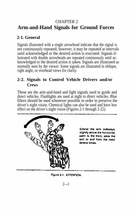
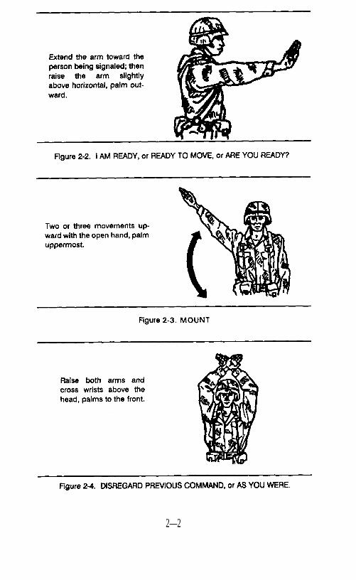
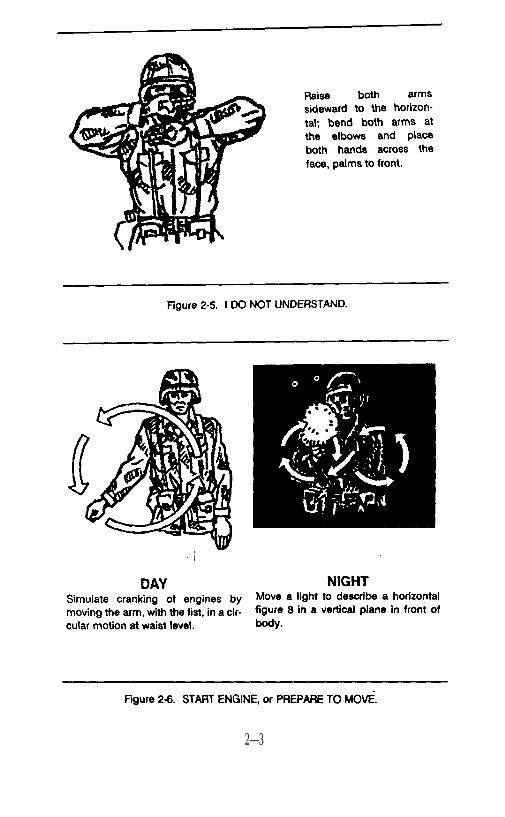
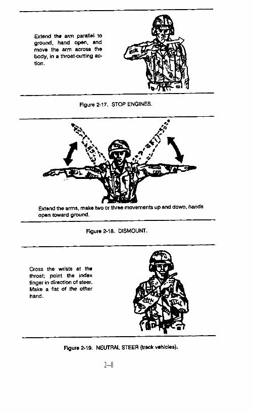
Signals illustrated with a single arrowhead indicate that the signal isnot continuously repeated; however, it may be repeated at intervalsuntil acknowledged or the desired action is executed. Signals il-lustrated with double arrowheads are repeated continuously until ac-knowledged or the desired action is taken. Signals are illustrated asnormally seen by the viewer. Some signals are illustrated in oblique,right angle, or overhead views for clarity.
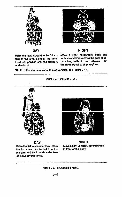
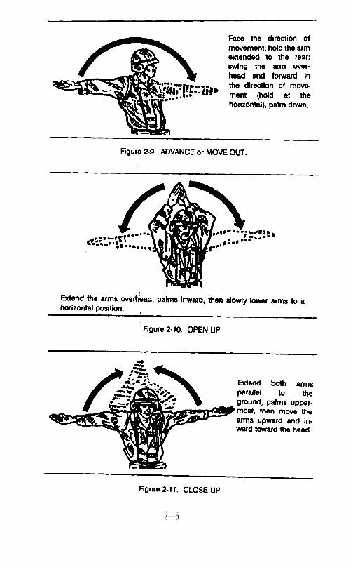
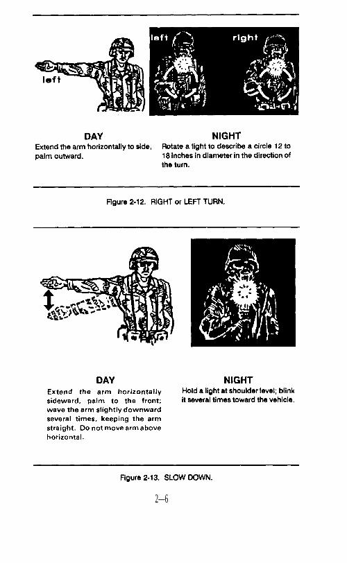
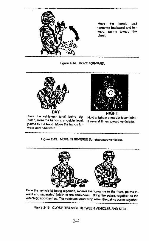
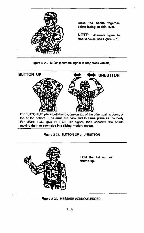
2-2. Signals to Control Vehicle Drivers and/or Crews
These are the arm-and-hand and light signals used to guide anddirect vehicles. Flashlights are used at night to direct vehicles. Bluefilters should be used whenever possible in order to preserve thedriver’s night vision. Chemical lights can also be used and have lesseffect on the driver’s night vision (Figures 2-1 through 2-22).
2—1
2—2
2—3
2—4
2—5
2—6
2—7
2—8
2—9
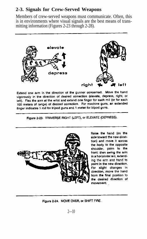
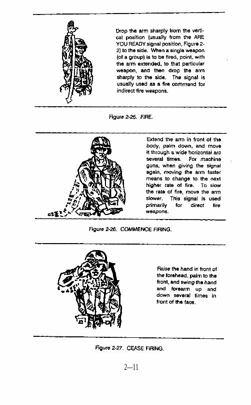
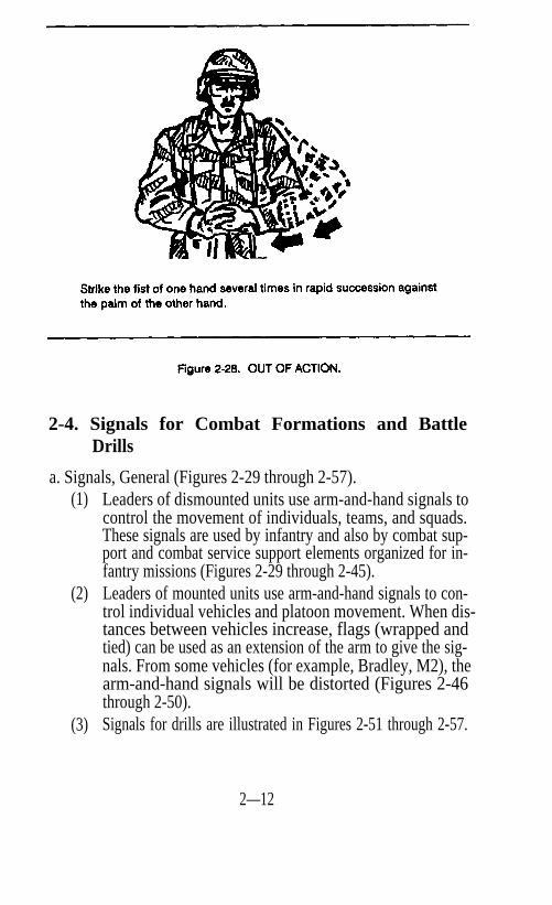
2-3. Signals for Crew-Served Weapons Members of crew-served weapons must communicate. Often, thisis in environments where visual signals are the best means of trans-mitting information (Figures 2-23 through 2-28).
2—10
2—11
2-4. Signals for Combat Formations and BattleDrills
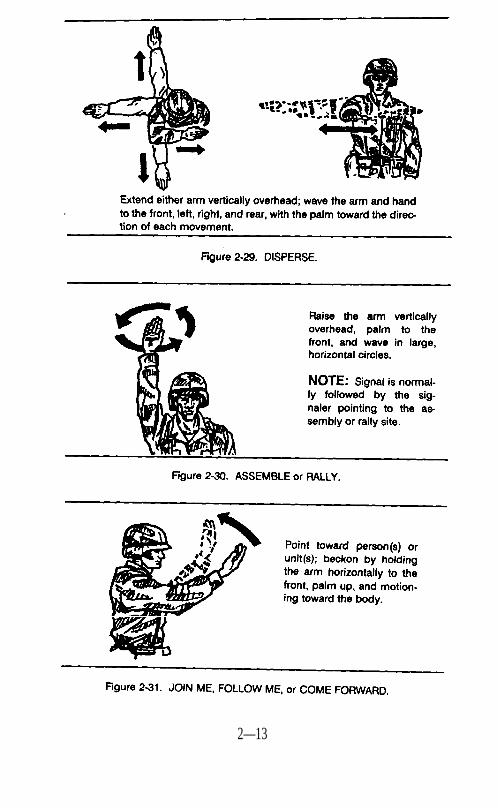
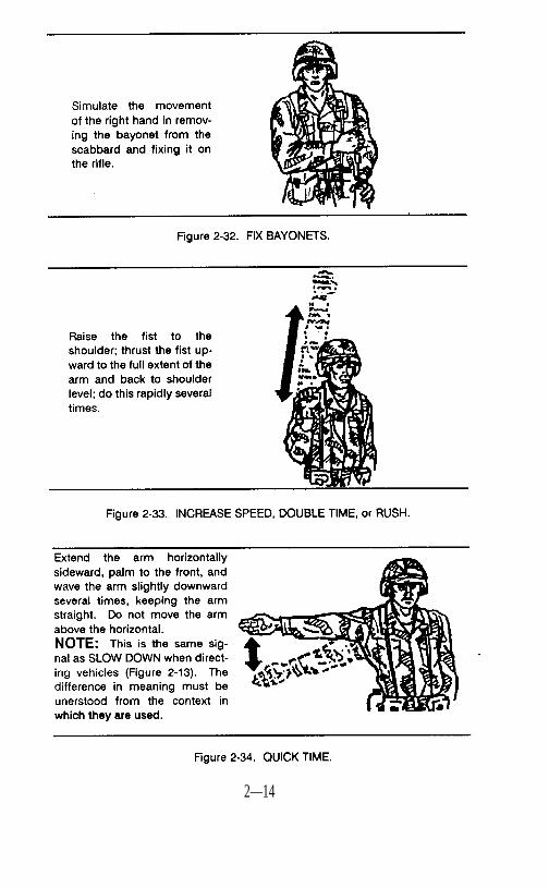
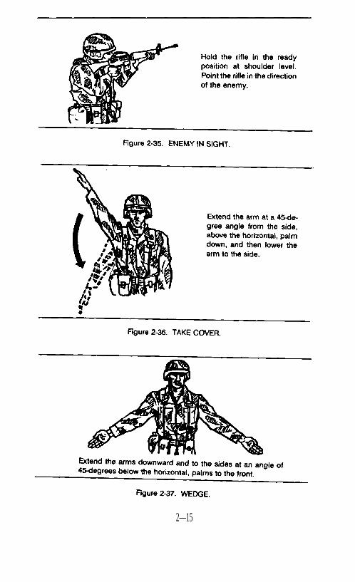
a. Signals, General (Figures 2-29 through 2-57).(1)
(2)
(3)
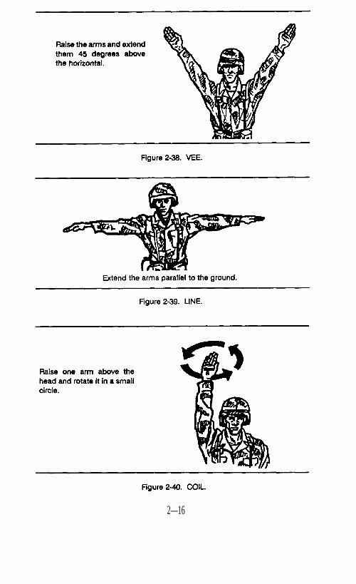
Leaders of dismounted units use arm-and-hand signals tocontrol the movement of individuals, teams, and squads.These signals are used by infantry and also by combat sup-port and combat service support elements organized for in-fantry missions (Figures 2-29 through 2-45).Leaders of mounted units use arm-and-hand signals to con-trol individual vehicles and platoon movement. When dis-tances between vehicles increase, flags (wrapped andtied) can be used as an extension of the arm to give the sig-nals. From some vehicles (for example, Bradley, M2), thearm-and-hand signals will be distorted (Figures 2-46through 2-50).Signals for drills are illustrated in Figures 2-51 through 2-57.
2—12
2—13
2—14
2—15
2—16
2—17
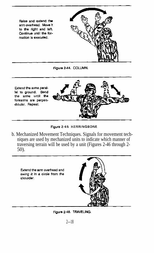
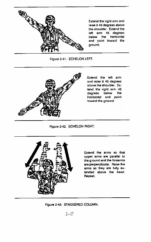
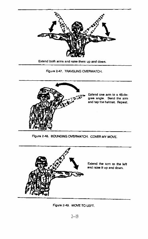
b. Mechanized Movement Techniques. Signals for movement tech-niques are used by mechanized units to indicate which manner oftraversing terrain will be used by a unit (Figures 2-46 through 2-50).
2—18
2—19
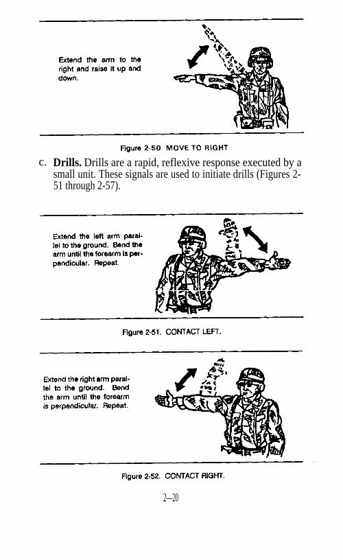
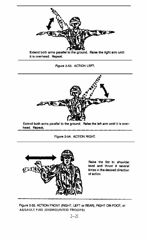
c. Drills. Drills are a rapid, reflexive response executed by asmall unit. These signals are used to initiate drills (Figures 2-51 through 2-57).
2—20
2—21
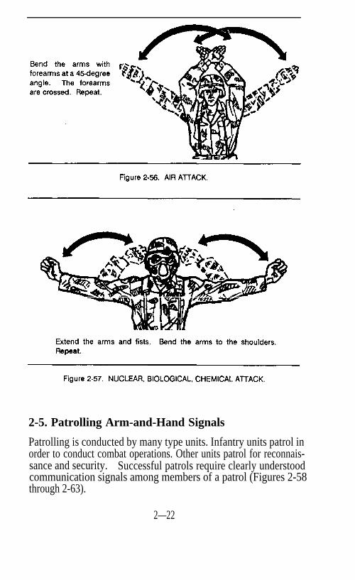
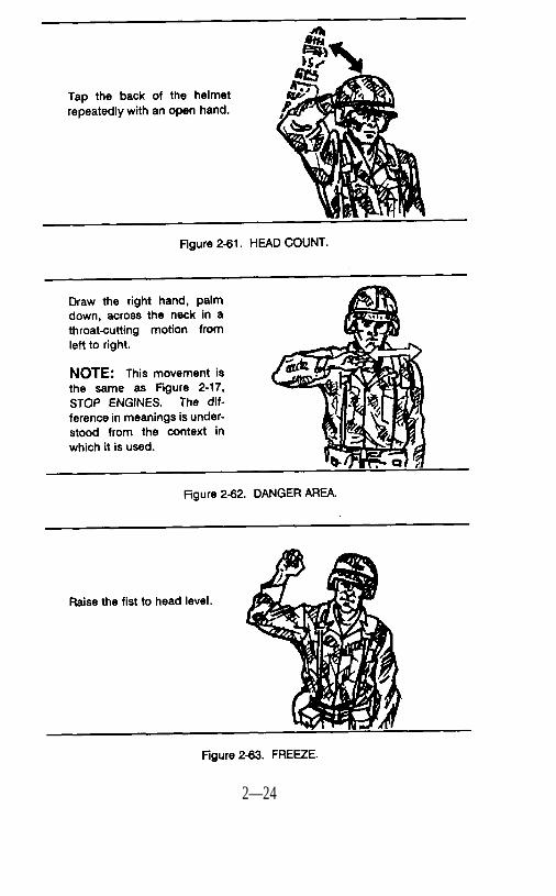
2-5. Patrolling Arm-and-Hand Signals
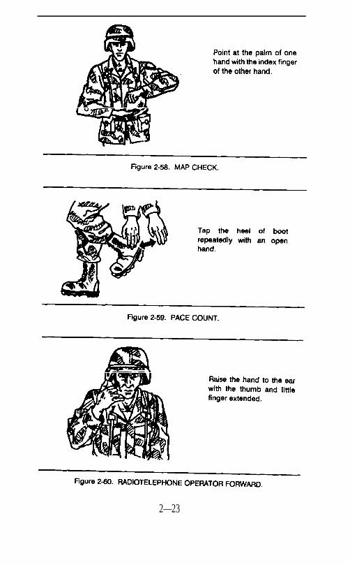
Patrolling is conducted by many type units. Infantry units patrol inorder to conduct combat operations. Other units patrol for reconnais-sance and security. Successful patrols require clearly understoodcommunication signals among members of a patrol (Figures 2-58through 2-63).
2—22
2—23
2—24
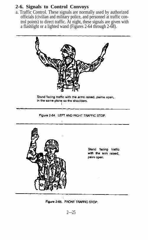
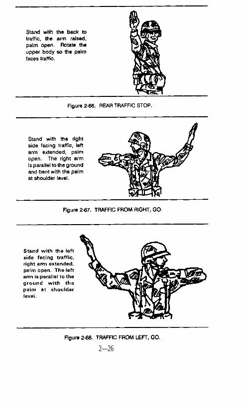
2-6. Signals to Control Convoysa. Traffic Control. These signals are normally used by authorized
officials (civilian and military police, and personnel at traffic con-trol points) to direct traffic. At night, these signals are given witha flashlight or a lighted wand (Figures 2-64 through 2-68).
2—25
2—26
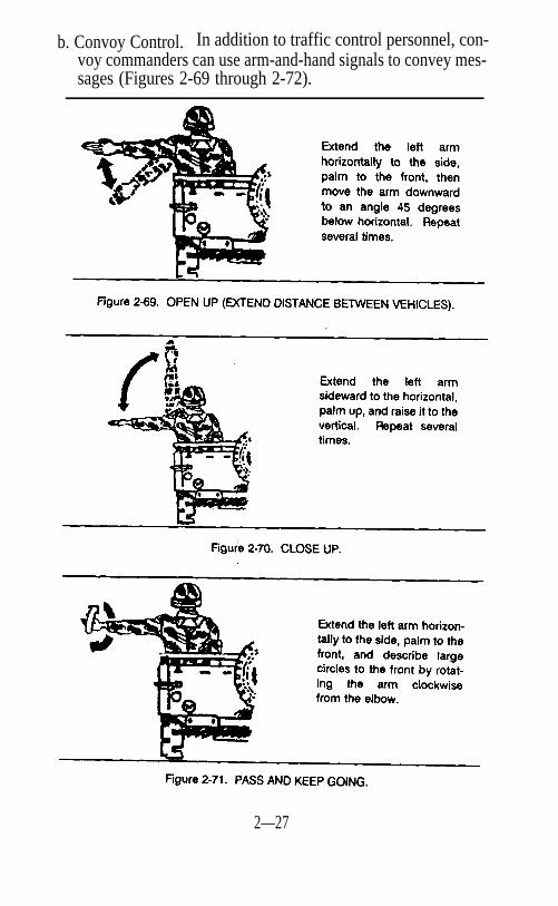
b. Convoy Control. In addition to traffic control personnel, con-voy commanders can use arm-and-hand signals to convey mes-sages (Figures 2-69 through 2-72).
2—27
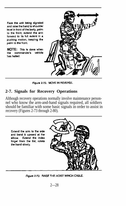
2-7. Signals for Recovery Operations
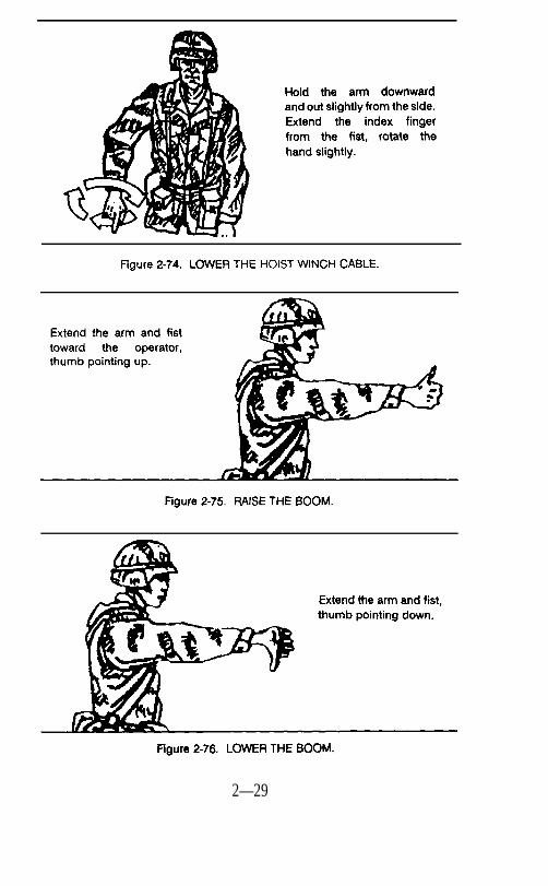
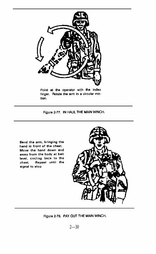
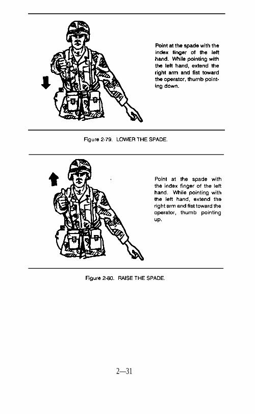
Although recovery operations normally involve maintenance person-nel who know the arm-and-hand signals required, all soldiersshould be familiar with some basic signals in order to assist inrecovery (Figures 2-73 through 2-80).
2—28
2—29
2—30
2—31
CHAPTER 3FLAG SIGNALS FOR ARMORED AND
MECHANIZED UNITS
3-1. GENERAL
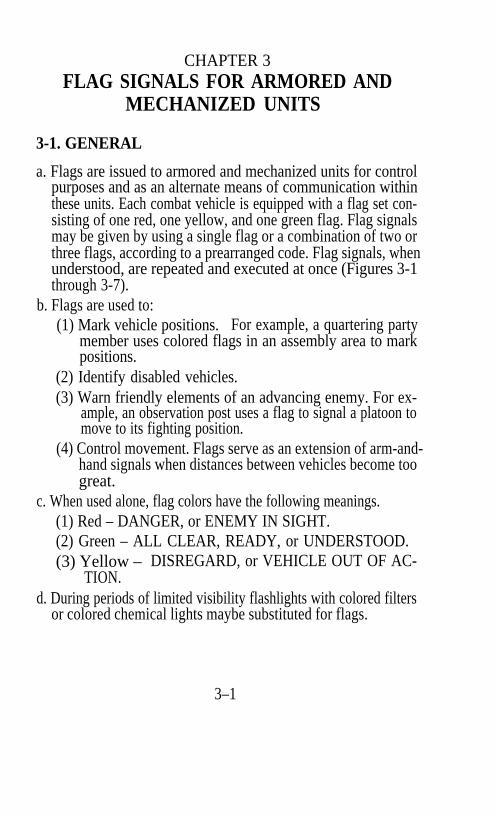
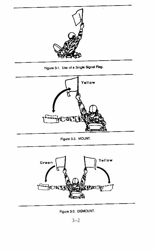
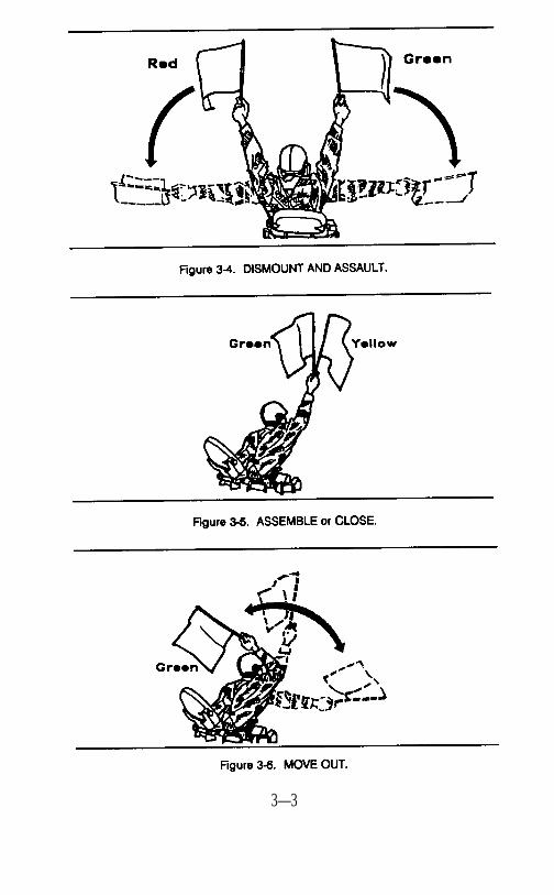
a. Flags are issued to armored and mechanized units for controlpurposes and as an alternate means of communication withinthese units. Each combat vehicle is equipped with a flag set con-sisting of one red, one yellow, and one green flag. Flag signalsmay be given by using a single flag or a combination of two orthree flags, according to a prearranged code. Flag signals, whenunderstood, are repeated and executed at once (Figures 3-1through 3-7).
b. Flags are used to:(1) Mark vehicle positions. For example, a quartering party
member uses colored flags in an assembly area to markpositions.
(2) Identify disabled vehicles.(3) Warn friendly elements of an advancing enemy. For ex-
ample, an observation post uses a flag to signal a platoon tomove to its fighting position.
(4) Control movement. Flags serve as an extension of arm-and-hand signals when distances between vehicles become toogreat.
c. When used alone, flag colors have the following meanings.(1) Red – DANGER, or ENEMY IN SIGHT.(2) Green – ALL CLEAR, READY, or UNDERSTOOD.(3) Yellow – DISREGARD, or VEHICLE OUT OF AC-
TION.d. During periods of limited visibility flashlights with colored filters
or colored chemical lights maybe substituted for flags.
3–1
3—2
3—3
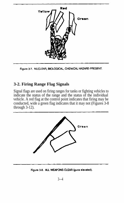
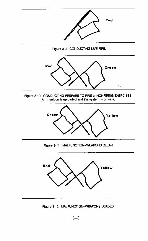
3-2. Firing Range Flag Signals
Signal flags are used on firing ranges for tanks or fighting vehicles toindicate the status of the range and the status of the individualvehicle. A red flag at the control point indicates that firing may beconducted, wide a green flag indicates that it may not (Figures 3-8through 3-12).
3—4
.
3—5
CHAPTER 4PYROTECHNICS
4-1. GENERAL
Pyrotechnics produce either smoke or light and are consumed in theprocess. When used for communications, prearranged orprescribed signals are developed and used throughout a unit. Thesesignals are developed based on the color and characteristics of thepyrotechnic device used. Pyrotechnic signals supplement or replacenormal means of communication and allow a large number of troopsand/or isolated units to be signaled quickly. They can be used forfriendly unit identification, maneuver element control, fire supportcontrol, target marking, and location reports. When pyrotechnicsare used, the signal and its meaning are included in the commandand signal portion of the operation order and in the unit’s com-munications-electronics operating instructions.
WARNINGDO NOT DISCHARGE PYROTECHNICS IN THE VICINITY OFAIRCRAFT FLYING IN THE AREA.
4-2. Description
Pyrotechnics are usually issued as complete rounds. There are twocommon types of military pyrotechnics used for signaling--hand-held devices and ground smoke. (The M203 grenade launcher canfire pyrotechnic rounds; see FM 23-31.)
4-3. Handheld Signals
a. Handheld signals are rocket-propelled, fin-stabilized, and consistof three concentric tubes. The outer tube is the container, thenext is the launcher, and inside the launcher is the fin-stabilizedtube containing the rocket propellant and signal element. Whenfired, the fin-stabilized tube is lifted about 50 feet in the air, thesignal element is expelled, and it burns from 4 to 42 seconds,(depending upon the type of signal: cluster, or parachute devices).
4–1
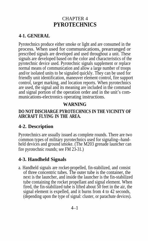
b. The following types of handheld signal rockets are available.(1) Star Clusters. Star clusters are used for signaling and il-
luminating. They are issued in an expendable launcherthat consists of a launching tube and a firing cap. These sig-nals produce a cluster of five free-falling pyrotechnic stars.Star clusters are available in green, red, and white (Figure 4-1).
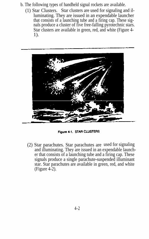
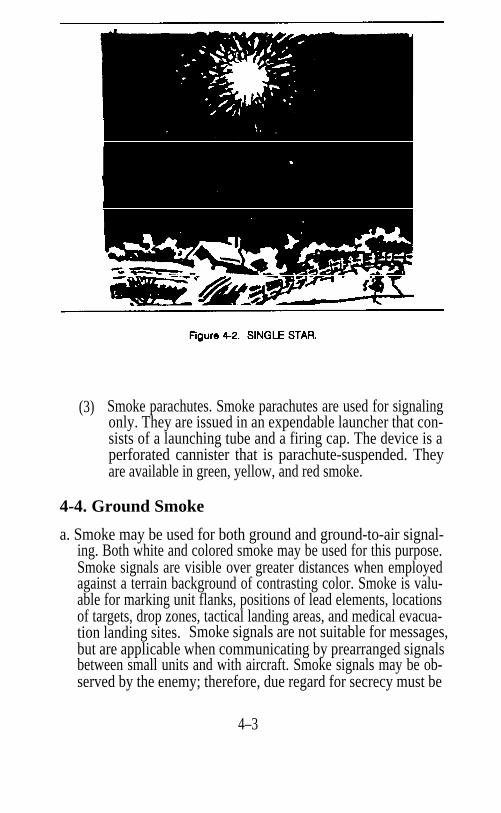
(2) Star parachutes. Star parachutes are used for signalingand illuminating. They are issued in an expendable launch-er that consists of a launching tube and a firing cap. Thesesignals produce a single parachute-suspended illuminantstar. Star parachutes are available in green, red, and white(Figure 4-2).
4–2
(3) Smoke parachutes. Smoke parachutes are used for signalingonly. They are issued in an expendable launcher that con-sists of a launching tube and a firing cap. The device is aperforated cannister that is parachute-suspended. Theyare available in green, yellow, and red smoke.
4-4. Ground Smoke
a. Smoke may be used for both ground and ground-to-air signal-ing. Both white and colored smoke may be used for this purpose.Smoke signals are visible over greater distances when employedagainst a terrain background of contrasting color. Smoke is valu-able for marking unit flanks, positions of lead elements, locationsof targets, drop zones, tactical landing areas, and medical evacua-tion landing sites. Smoke signals are not suitable for messages,but are applicable when communicating by prearranged signalsbetween small units and with aircraft. Smoke signals may be ob-served by the enemy; therefore, due regard for secrecy must be
4–3
b.
considered to try and avoid disclosing position locations and/ora unit’s intentions.Smoke grenades are available in white, green, yellow, red, andviolet smoke. This color range is provided by two types ofgrenades.(1)
(2)
The white smoke hand grenade is a burning-type grenadeused for signaling and for laying smoke screens. When ig-nited, it produces dense white smoke for 105 to 150 seconds.It will not normally injure exposed troops. In heavy con-centrations, troops should wear the field protective mask.However, the mask will not protect against heavy concentra-tions of this smoke in enclosed spaces due to oxygen deple-tion and carbon monoxide buildup.The M18 colored smoke grenade is similar in appearance tothe white smoke grenade, but its top is painted the color ofthe smoke it produces. Its filler is a burning-type mixturecontaining a dye; only four are standard: red, green, violet,and yellow. As a burning-type grenade, it has an igniting-type fuse, and burns 50 to 90 seconds.
4–4
CHAPTER 5SIGNALS TO AIRCRAFT
5-1. General
With the introduction of the airplane and helicopter to the combinedarms team, a new requirement for communication was added to thebattlefield. Ground troops and air forces need to communicate.There will be times when radios cannot be used and visual signalsmust be used. Therefore, systems of standard visual signals havebeen developed to allow ground-to-air communication. These sys-tems include arm-and-hand signals used by ground forces to directhelicopters in direct support; devices that can be used to communi-cate with aircraft; and ground-to-air emergency signals and codes.
5-2 Arm-and-Hand Ground Signals
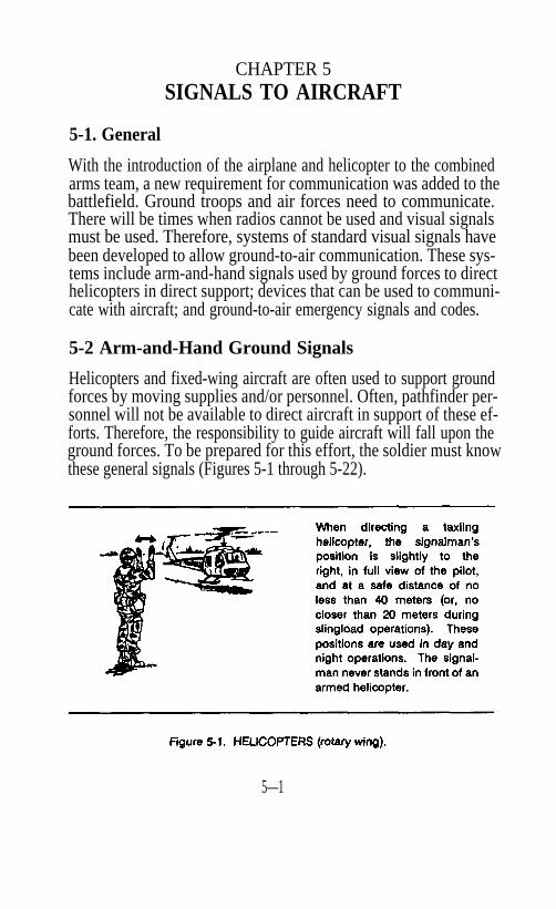
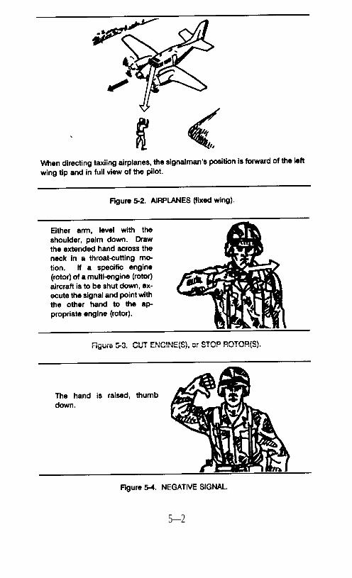
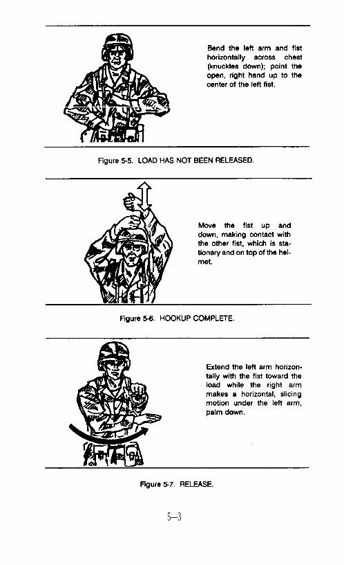
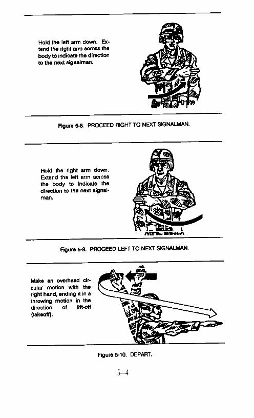
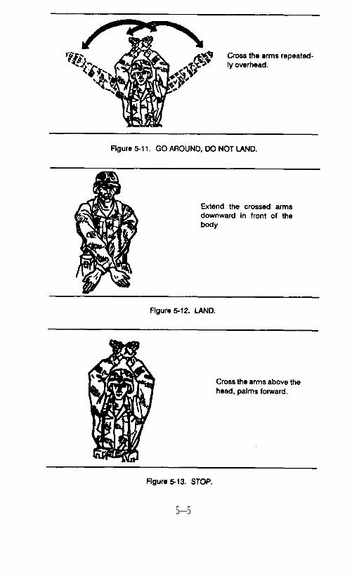
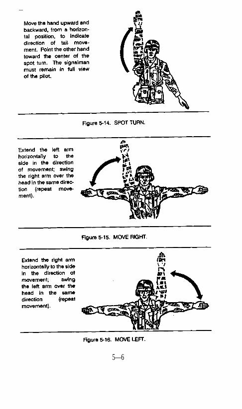
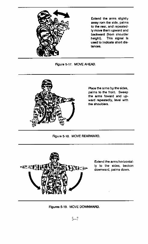
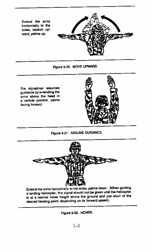
Helicopters and fixed-wing aircraft are often used to support groundforces by moving supplies and/or personnel. Often, pathfinder per-sonnel will not be available to direct aircraft in support of these ef-forts. Therefore, the responsibility to guide aircraft will fall upon theground forces. To be prepared for this effort, the soldier must knowthese general signals (Figures 5-1 through 5-22).
5—1
5—2
5—3
5—4
5—5
5—6
5—7
5—8
5-3. Ground-to-Air Panel System
a. The panel system is a method ground troops use to communicate,to a limited degree, with aircraft by displaying panels on theground. There are two types of panels: marking and identify-ing colored panels, and black and white panels for transmittingmessages.(1) The marking and identifying panels are made in fluorescent
colors. The panels are used to mark positions and identifyfriendly units. These panels can be ordered through thesupply system using the nomenclature Panel Marker, Aerial,Liaison (Figure 5-23).
(2) Black and white panel sets are arranged on light or dark ter-rain backgrounds. They are used to transmit brief messagesor to identify a unit. This is done by using the combinedpanel system and the panel recognition code in the unit’scommunications-electronics operating instructions.
b. Panels (if constructed locally) should be large enough to permiteasy reading from the air. There should be as much color con-trast as possible between the symbols and the background.Panels should beat least six feet long and two feet wide.
c. Select a relatively flat, clear area of ground about 40 by 130feet. This area is large enough to display messages and specialsigns. For message drop and pickup, the area should be clear ofobstacles which could prevent aircraft from flying into the windat reduced airspeed and low altitude.
d. When using the panel system, one of the panels is used as a basepanel. Place the base panels first and keep them in place as longas panel signaling is in progress. The distance between panelsis one panel length throughout, when space is available.Change from one panel figure to another as soon as possible byshifting, adding, or removing panels (other than the base panels).The index panel is the first removed and the last laid out whenthe display is changed. Remove all panels from view that are notused for a particular display.
5—9
.
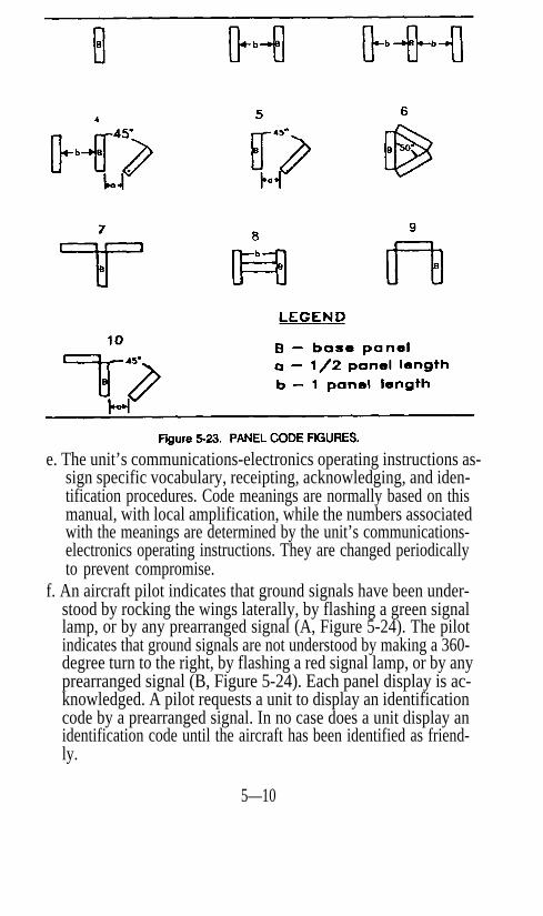
e. The unit’s communications-electronics operating instructions as-sign specific vocabulary, receipting, acknowledging, and iden-tification procedures. Code meanings are normally based on thismanual, with local amplification, while the numbers associatedwith the meanings are determined by the unit’s communications-electronics operating instructions. They are changed periodicallyto prevent compromise.
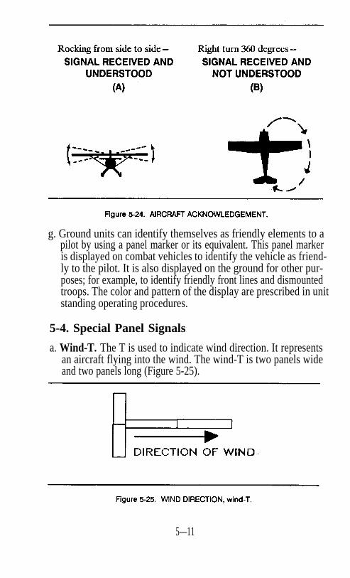
f. An aircraft pilot indicates that ground signals have been under-stood by rocking the wings laterally, by flashing a green signallamp, or by any prearranged signal (A, Figure 5-24). The pilotindicates that ground signals are not understood by making a 360-degree turn to the right, by flashing a red signal lamp, or by anyprearranged signal (B, Figure 5-24). Each panel display is ac-knowledged. A pilot requests a unit to display an identificationcode by a prearranged signal. In no case does a unit display anidentification code until the aircraft has been identified as friend-ly.
5—10
g. Ground units can identify themselves as friendly elements to apilot by using a panel marker or its equivalent. This panel markeris displayed on combat vehicles to identify the vehicle as friend-ly to the pilot. It is also displayed on the ground for other pur-poses; for example, to identify friendly front lines and dismountedtroops. The color and pattern of the display are prescribed in unitstanding operating procedures.
5-4. Special Panel Signals
a. Wind-T. The T is used to indicate wind direction. It representsan aircraft flying into the wind. The wind-T is two panels wideand two panels long (Figure 5-25).
5—11
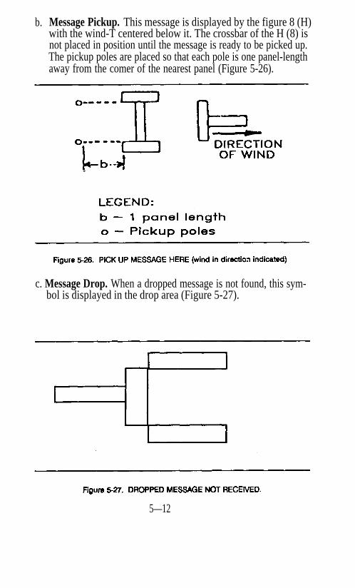
b. Message Pickup. This message is displayed by the figure 8 (H)with the wind-T centered below it. The crossbar of the H (8) isnot placed in position until the message is ready to be picked up.The pickup poles are placed so that each pole is one panel-lengthaway from the comer of the nearest panel (Figure 5-26).
c. Message Drop. When a dropped message is not found, this sym-bol is displayed in the drop area (Figure 5-27).
5—12
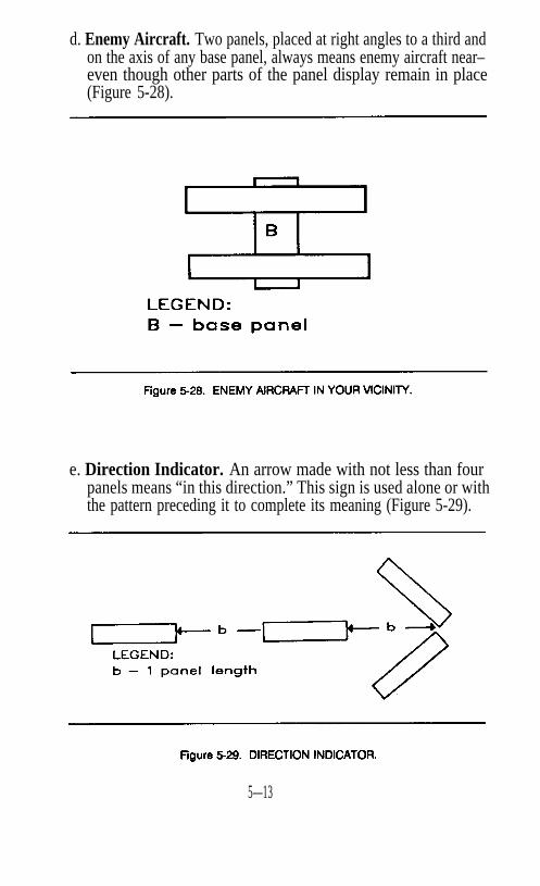
d. Enemy Aircraft. Two panels, placed at right angles to a third andon the axis of any base panel, always means enemy aircraft near–even though other parts of the panel display remain in place(Figure 5-28).
e. Direction Indicator. An arrow made with not less than fourpanels means “in this direction.” This sign is used alone or withthe pattern preceding it to complete its meaning (Figure 5-29).
5—13
5-5. Ground-to-Air Emergency Signals and Codes
a.
b.
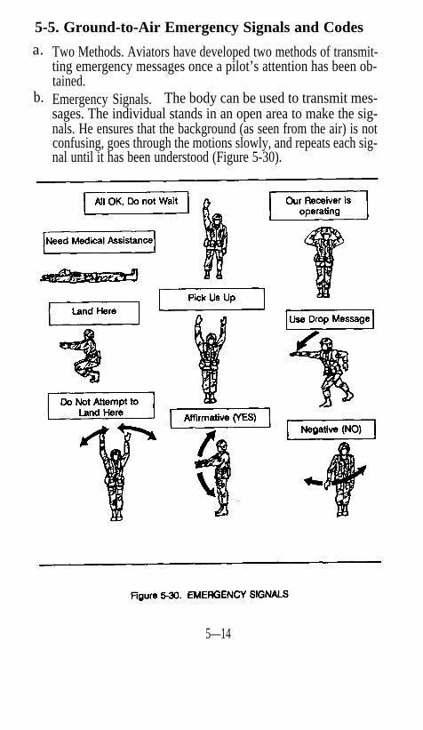
Two Methods. Aviators have developed two methods of transmit-ting emergency messages once a pilot’s attention has been ob-tained.Emergency Signals. The body can be used to transmit mes-sages. The individual stands in an open area to make the sig-nals. He ensures that the background (as seen from the air) is notconfusing, goes through the motions slowly, and repeats each sig-nal until it has been understood (Figure 5-30).
5—14
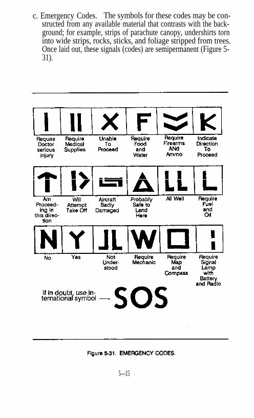
c. Emergency Codes. The symbols for these codes may be con-structed from any available material that contrasts with the back-ground; for example, strips of parachute canopy, undershirts torninto wide strips, rocks, sticks, and foliage stripped from trees.Once laid out, these signals (codes) are semipermanent (Figure 5-31).
5—15
5-6. Signaling With Mirrors and Strobes
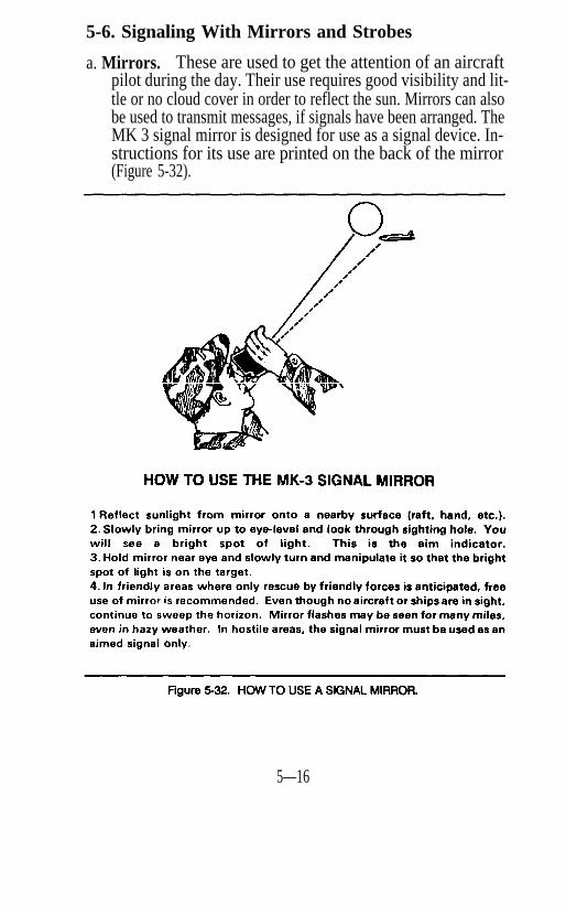
a. Mirrors. These are used to get the attention of an aircraftpilot during the day. Their use requires good visibility and lit-tle or no cloud cover in order to reflect the sun. Mirrors can alsobe used to transmit messages, if signals have been arranged. TheMK 3 signal mirror is designed for use as a signal device. In-structions for its use are printed on the back of the mirror(Figure 5-32).
5—16
b. Strobes. These can be used at night to identify positions. If priorcoordination has been conducted with supporting aviation units,strobes may also be used to signal pilots. In order to reducedetection when used, strobe lights should be placed in holes sothey can only be viewed from above. Strobes with infrared coverscan be used if there has been prior coordination with the aircrew.Strobes are ordered using the nomenclature Distress Markers.
5—17
FM 21–60
REFERENCESRequired Publications
Required publications are sources that users must read in order tounderstand or to comply with this publication.None
Related Publications
Related publications are sources of additional information. They arenot required in order to understand this publication.
Army Regulation (AR)310-25 Dictionary of United States Army Terms310-50 Authorized Abbreviations, Brevity Codes, and
Acronyms
Field Manual (FM)1-3001-4003-49-1317-15 (Test)17-9820-2221-17
21-7621-30521-30623-3023-3123-9224-1
Flight Operations and Airfield ManagementAviator’s HandbookNBC ProtectionAmmunition HandbookTank Platoon Division 86The Army 86 Scout PlatoonVehicle Recovery OperationsDriver Selection, Training, and Supervision, TrackCombat VehiclesSurvivalManual for the Wheeled Vehicle DriveManual for the Track Combat Vehicle DriveGrenades and Pyrotechnic Signals40-mm Grenade Launchers, M203 and M794.2-inch Mortar, M30Combat Communications
References–1
55-450-1 Army Helicopter External Load Operations57-38 Pathfinder Operations57-220 Basic Parachuting Techniques and Training
Soldier’s Training Publication (STP)7-llB1 (SM) Soldier’s Manual, llB, Infantryman (Skill Level 1)21-1 (SMCT) Soldier’s Manual of Common Tasks (Skill Level 1)
Department of the Army Pamphlet (DA Pam)310-35 Index of International Standardization Agreements
NATO STANAG* No.Recognition and Identification of Forces 2129Aircraft Marshalling Signals 3117Inflight Visual Signals 3379Drop Zones: Visual Signals 3570
QSTAG* No.Tactical Hand-and-Arm Signalsfor the Control of AFVs 573
*The acronyms are defined as follows: North Atlantic Treaty Or-ganization (NATO), Standardization Agreement (STANAG), Quad-ripartite Standardization Agreement (QSTAG). Standardizationagreements are available from the Naval Publication sand FormsCenter, 5801 Tabor Avenue, Philadelphia, PA 19120. DD Form 1425(Specifications and Standards Requisition) is used to requisitionthese documents.
References–2

PIN: 007200-000